ultra wideband impulse radio superregenerative reception … · 2017-05-09 · combined with modern...
TRANSCRIPT

7
Ultra Wideband Impulse Radio Superregenerative Reception
F. Xavier Moncunill-Geniz, Pere Palà-Schönwälder, Jordi Bonet-Dalmau, Francisco del Águila-López and Rosa Giralt-Mas
Universitat Politècnica de Catalunya Spain
1. Introduction Since the superregenerative (SR) receiver was invented by E. H. Armstrong in 1922 (Armstrong, 1922), it has been used in myriad applications. In the 1930s, it came into widespread use by radio amateurs as an economical communications receiver. Various walkie-talkie communications devices were developed based on SR receivers, exploiting their light weight and low cost. With the advent of World War II, the circuit was mass-produced as a pulse responder for radar identification of ships and aircraft (Identification, Friend or Foe (I.F.F.)) (Whitehead, 1950). As the transistor replaced the vacuum tube, the superheterodyne receiver, characterized by improved selectivity, relegated SR receivers to very specific applications, such as altitude and Doppler radar (Levanon et al., 1974; Milner & Shell, 1968), and solar-powered devices (McCoy, 1992). Superregenerative receivers have also harnessed for optical communications (España & Puerta, 1999). Currently, SR receivers are chiefly used in short-distance radiofrequency (RF) links, which demand low cost and low power consumption. These include remote control systems (e.g. garage-door openers, robotics, and radio-controlled toys), short distance telemetry, and wireless security (Hickman, 2002; Telecontrolli, 2011). These receivers are typically used as narrowband AM receivers and, occasionally, as FM receivers. Superregenerative receivers have recently garnered renewed attention for their integration into CMOS, which, when combined with modern digital techniques in mixed-signal designs, improves performance implementations (Favre et al., 1998; Chen et al., 2007). Thus, SR receivers are a promising alternative to other architectures in emerging applications such as wireless sensor networks and medical devices (Ayers et al., 2010, Bohorquez et al., 2009; Otis et al., 2005). Recent proposals for their use include: reception of spread spectrum, phase and frequency modulations (Ayers et al. 2010, Moncunill et al., 2005b; Palà et al., 2009); use of stable frequency references such as bulk-acoustic-wave (BAW) resonators (Otis et al., 2005); implementation of digital self-calibrating techniques (Chen et al., 2007); and, very recently, reception of ultra wideband impulse radio (UWB IR) modulations (Anis et al., 2008; Moncunill et al., 2007b; Moncunill et al., 2009; Pelissier et al., 2009; Thoppay, 2010). In this chapter, we analyze the suitability of SR receivers for UWB IR communications. In Section 2, we provide basic concepts on the principle of superregeneration. In Section 3, we present several SR architectures and assess their amenability to UWB IR signal detection. In Section 4, we characterize the superregenerative oscillator as a pulse filter and amplifier with characteristic parameters and functions. In Section 5, we outline the features that
Ultra Wideband Communications: Novel Trends �– System, Architecture and Implementation
114
superregenerative oscillators require for use as a UWB IR receiver. In Section 6, we assess the expected performance from these types of receivers, and finally, in Section 7, we present the main conclusions from this chapter.
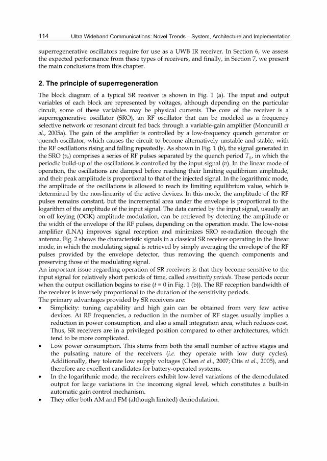
2. The principle of superregeneration The block diagram of a typical SR receiver is shown in Fig. 1 (a). The input and output variables of each block are represented by voltages, although depending on the particular circuit, some of these variables may be physical currents. The core of the receiver is a superregenerative oscillator (SRO), an RF oscillator that can be modeled as a frequency selective network or resonant circuit fed back through a variable-gain amplifier (Moncunill et al., 2005a). The gain of the amplifier is controlled by a low-frequency quench generator or quench oscillator, which causes the circuit to become alternatively unstable and stable, with the RF oscillations rising and falling repeatedly. As shown in Fig. 1 (b), the signal generated in the SRO (vo) comprises a series of RF pulses separated by the quench period Tq , in which the periodic build-up of the oscillations is controlled by the input signal (v). In the linear mode of operation, the oscillations are damped before reaching their limiting equilibrium amplitude, and their peak amplitude is proportional to that of the injected signal. In the logarithmic mode, the amplitude of the oscillations is allowed to reach its limiting equilibrium value, which is determined by the non-linearity of the active devices. In this mode, the amplitude of the RF pulses remains constant, but the incremental area under the envelope is proportional to the logarithm of the amplitude of the input signal. The data carried by the input signal, usually an on-off keying (OOK) amplitude modulation, can be retrieved by detecting the amplitude or the width of the envelope of the RF pulses, depending on the operation mode. The low-noise amplifier (LNA) improves signal reception and minimizes SRO re-radiation through the antenna. Fig. 2 shows the characteristic signals in a classical SR receiver operating in the linear mode, in which the modulating signal is retrieved by simply averaging the envelope of the RF pulses provided by the envelope detector, thus removing the quench components and preserving those of the modulating signal. An important issue regarding operation of SR receivers is that they become sensitive to the input signal for relatively short periods of time, called sensitivity periods. These periods occur when the output oscillation begins to rise (t = 0 in Fig. 1 (b)). The RF reception bandwidth of the receiver is inversely proportional to the duration of the sensitivity periods. The primary advantages provided by SR receivers are: • Simplicity: tuning capability and high gain can be obtained from very few active
devices. At RF frequencies, a reduction in the number of RF stages usually implies a reduction in power consumption, and also a small integration area, which reduces cost. Thus, SR receivers are in a privileged position compared to other architectures, which tend to be more complicated.
• Low power consumption. This stems from both the small number of active stages and the pulsating nature of the receivers (i.e. they operate with low duty cycles). Additionally, they tolerate low supply voltages (Chen et al., 2007; Otis et al., 2005), and therefore are excellent candidates for battery-operated systems.
• In the logarithmic mode, the receivers exhibit low-level variations of the demodulated output for large variations in the incoming signal level, which constitutes a built-in automatic gain control mechanism.
• They offer both AM and FM (although limited) demodulation.
Ultra Wideband Impulse Radio Superregenerative Reception
115
• Lastly, and paramount to this chapter, SR receivers are very well suited to UWB IR communications, due to the low duty cycle of the received signals.
Traditionally, SR receivers have had three major drawbacks: • Excessive reception bandwidth when applied to narrowband communications. Because
of their relatively short sensitivity periods, their RF bandwidth is much wider than the signal modulation bandwidth, making them more sensitive to noise and interference compared to other systems.
• Frequency instability in tank (LC) implementations due to temperature changes, mechanical shock, etc. This problem, which is not exclusive of SR receivers, can be overcome via stable frequency references, such as coaxial ceramic resonators or acoustic wave devices (e.g., SAW, BAW and FBAR).
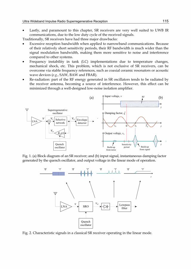
• Re-radiation: part of the RF energy generated in SR oscillators tends to be radiated by the receiver antenna, becoming a source of interference. However, this effect can be minimized through a well-designed low-noise isolation amplifier.
Selectivenetwork
Quenchoscillator
LNA v
Superregenerative oscillator
vo
Ka(t)
Envelopedetector
vs
va
Tq 0 tb
( ) t
t
Output voltaje, vo
Input voltaje, v
t
Sensitivity period Build-up
from noise Build-up
from signal
RF
ta
Damping factor, !
Fig. 1. (a) Block diagram of an SR receiver; and (b) input signal, instantaneous damping factor generated by the quench oscillator, and output voltage in the linear mode of operation.
t
�“1�” �“0�”
t
�“1�” �“0�”
t
�“1�”�“0�”
t
�“1�” �“0�”
Lowpass filter
Quenchoscillator
SROLNAvOv vE
vF
Fig. 2. Characteristic signals in a classical SR receiver operating in the linear mode.
(a) (b)
Ultra Wideband Communications: Novel Trends �– System, Architecture and Implementation
116
3. Superregenerative architectures for narrowband, wideband and UWB signal reception Although SR receivers have traditionally been used in short-range narrowband communications, new modes for their operation have been proposed and evaluated over the past few years. In this section, we describe and compare these operation modes and their corresponding receiver architectures to evaluate their suitability for UWB IR signal reception. Here we consider the simplest case of OOK modulation.
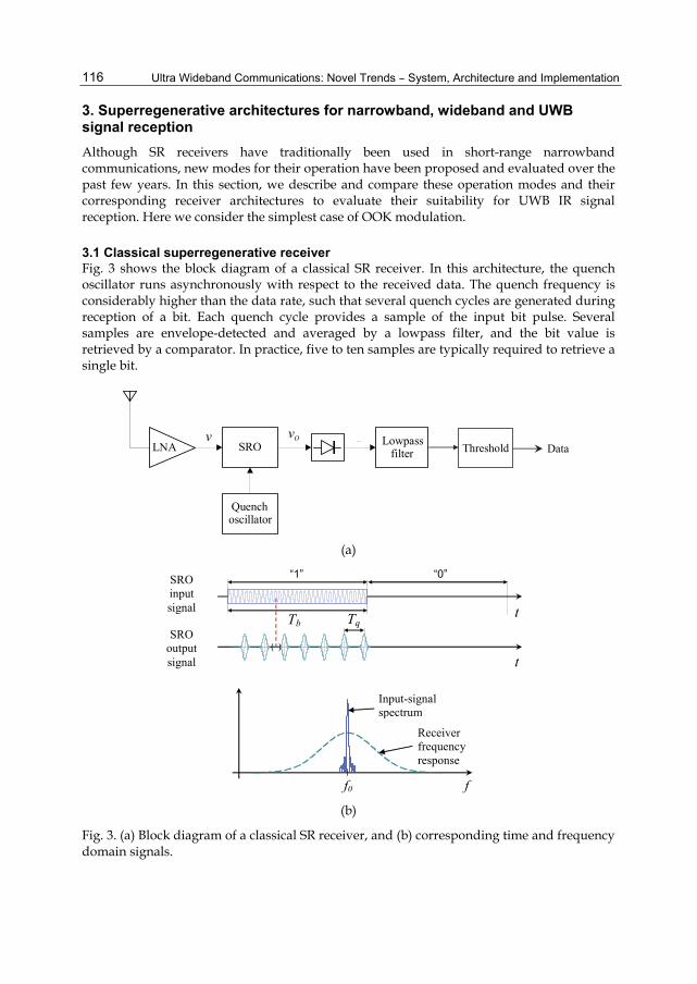
3.1 Classical superregenerative receiver Fig. 3 shows the block diagram of a classical SR receiver. In this architecture, the quench oscillator runs asynchronously with respect to the received data. The quench frequency is considerably higher than the data rate, such that several quench cycles are generated during reception of a bit. Each quench cycle provides a sample of the input bit pulse. Several samples are envelope-detected and averaged by a lowpass filter, and the bit value is retrieved by a comparator. In practice, five to ten samples are typically required to retrieve a single bit.
Lowpass filter
Quenchoscillator
SROLNAvOv vE
vF
Threshold Data
(a)
t
t Tb
SRO input signal
SRO output signal
f0 f
Receiver frequency response
Input-signal spectrum
�“1�” �“0�”
( )
Tq
(b)
Fig. 3. (a) Block diagram of a classical SR receiver, and (b) corresponding time and frequency domain signals.
Ultra Wideband Impulse Radio Superregenerative Reception
117
This architecture, characterized by a minimal number of constituting blocks, offers the following advantages: • Simplicity and low cost; • Low power consumption. However, it has several disadvantages: • Poor frequency selectivity: since the quench frequency is considerably higher than the
bit frequency, the sensitivity periods are much shorter than the bit periods (Tb); consequently, the RF bandwidth of the receiver is much larger than the modulation bandwidth.
• Poor sensitivity: the noise bandwidth is much greater than the signal bandwidth. • Not suitable for UWB IR communications: taking several samples of a UWB pulse is not
feasible, as it would require an excessively high quench frequency.
3.2 Synchronous superregenerative receiver In this architecture, shown in Fig. 4, the input signal is sampled synchronously at a rate of one sample per bit (Moncunill et al., 2007a). Thus, the required quench frequency is much lower than in a classical receiver, and therefore, the selectivity is significantly higher. Furthermore, since the quench frequency is equal to the bit rate, the RF bandwidth is closer to the signal bandwidth than in a classical receiver. Moreover, synchronous operation enables optimization of the transmitted bit pulse shape, as shown in Fig. 4 (c), which is done to concentrate the bit energy in the sensitivity periods of the receiver. Consequently, synchronous SR receivers can make more efficient use of the incoming signal than classical SR receivers, exhibiting greater sensitivity and requiring lower levels of transmitted power. Synchronous operation requires a synchronization phase-locked loop (PLL) that controls the quench voltage-controlled oscillator (VCO) to keep the quench cycles in phase with the received data. A proper error signal can be generated via early/late sampling of the received pulses, as shown in Fig. 5. In this case, the lowpass filter used by classical receivers to remove the quench components is not required, since each output pulse corresponds to a single bit. On one hand, synchronous SR receivers are amenable to narrowband communications, namely, to overcome the problems of classical receivers. On the other hand, provided that the SRO is designed to exhibit short sensitivity periods, this architecture is also very well suited for reception of UWB IR signals, as they comprise bursts of short RF pulses. This architecture offers the following advantages: • Simplicity and low cost; • Low power consumption; • High frequency selectivity, with RF bandwidth close or equal to the signal bandwidth. • High sensitivity: up to 10 dB better than that of a classical receiver, with values similar
to those offered by superheterodyne and zero-IF schemes. • Fast data rates: for a given quench frequency, this architecture maximizes the data rate. • Suitability for UWB IR communications, including OOK and pulse-position modulations. It has one major disadvantage: • It requires a PLL, which must be carefully designed to achieve effective acquisition and
tracking of the received signal. This point is especially relevant in UWB IR applications, which demand high-precision synchronization.

Ultra Wideband Communications: Novel Trends �– System, Architecture and Implementation
118
SRO
Synch.
vo vLNA
Quench VCO
Threshold Data
(a)
f0 f
t
t Tb = Tq
Input-signal spectrum Receiver
frequency response
( )
�“1�” �“0�” �“0�” �“0�” �“1�” �“1�” �“1�” SRO input signal
SRO output signal
(b)
f0 f
t
t Tb ( )
�“1�” �“0�” �“0�” �“0�” �“1�” �“1�” �“1�” SRO input signal
SRO output signal
Input-signal spectrum Receiver
frequency response
(c)
Fig. 4. (a) Block diagram of a synchronous SR receiver. Time and frequency domain signals (b) with a constant bit envelope and (c) with an envelope matched to the sensitivity periods of the receiver.
Ultra Wideband Impulse Radio Superregenerative Reception
119
1
1
Envelope of input pulse
Early sensitivity
curve
Late sensitivity curve
SRO output pulses
t
t
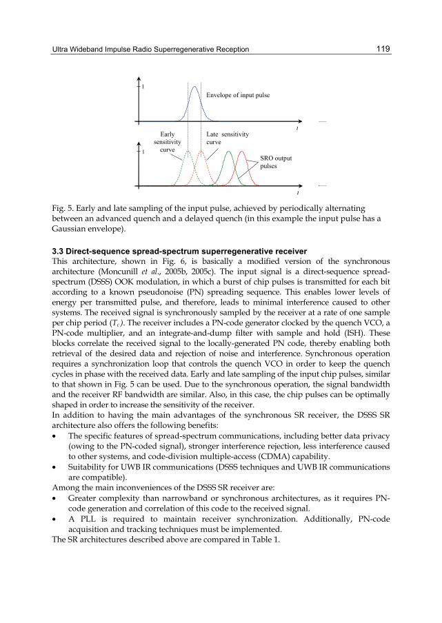
Fig. 5. Early and late sampling of the input pulse, achieved by periodically alternating between an advanced quench and a delayed quench (in this example the input pulse has a Gaussian envelope).
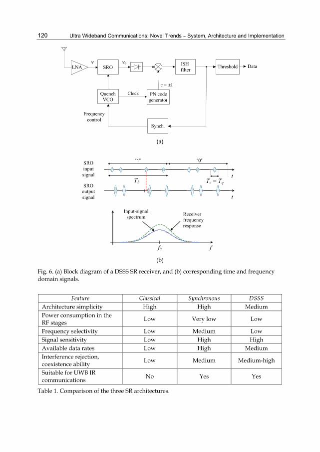
3.3 Direct-sequence spread-spectrum superregenerative receiver This architecture, shown in Fig. 6, is basically a modified version of the synchronous architecture (Moncunill et al., 2005b, 2005c). The input signal is a direct-sequence spread-spectrum (DSSS) OOK modulation, in which a burst of chip pulses is transmitted for each bit according to a known pseudonoise (PN) spreading sequence. This enables lower levels of energy per transmitted pulse, and therefore, leads to minimal interference caused to other systems. The received signal is synchronously sampled by the receiver at a rate of one sample per chip period (Tc ). The receiver includes a PN-code generator clocked by the quench VCO, a PN-code multiplier, and an integrate-and-dump filter with sample and hold (ISH). These blocks correlate the received signal to the locally-generated PN code, thereby enabling both retrieval of the desired data and rejection of noise and interference. Synchronous operation requires a synchronization loop that controls the quench VCO in order to keep the quench cycles in phase with the received data. Early and late sampling of the input chip pulses, similar to that shown in Fig. 5 can be used. Due to the synchronous operation, the signal bandwidth and the receiver RF bandwidth are similar. Also, in this case, the chip pulses can be optimally shaped in order to increase the sensitivity of the receiver. In addition to having the main advantages of the synchronous SR receiver, the DSSS SR architecture also offers the following benefits: • The specific features of spread-spectrum communications, including better data privacy
(owing to the PN-coded signal), stronger interference rejection, less interference caused to other systems, and code-division multiple-access (CDMA) capability.
• Suitability for UWB IR communications (DSSS techniques and UWB IR communications are compatible).
Among the main inconveniences of the DSSS SR receiver are: • Greater complexity than narrowband or synchronous architectures, as it requires PN-
code generation and correlation of this code to the received signal. • A PLL is required to maintain receiver synchronization. Additionally, PN-code
acquisition and tracking techniques must be implemented. The SR architectures described above are compared in Table 1.
Ultra Wideband Communications: Novel Trends �– System, Architecture and Implementation
120
SRO
PN codegenerator
Synch.
QuenchVCO
Frequencycontrol
Clock
ISH filter Threshold DataLNA
c = ±1
v vo
(a)
t
t Tb
�“1�” �“0�”
Tc = Tq ( )
SRO input signal
SRO output signal
f0 f
Input-signal spectrum Receiver
frequency response
(b)
Fig. 6. (a) Block diagram of a DSSS SR receiver, and (b) corresponding time and frequency domain signals.
Feature Classical Synchronous DSSS
Architecture simplicity High High Medium Power consumption in the RF stages Low Very low Low
Frequency selectivity Low Medium Low Signal sensitivity Low High High Available data rates Low High Medium Interference rejection, coexistence ability Low Medium Medium-high
Suitable for UWB IR communications No Yes Yes
Table 1. Comparison of the three SR architectures.

Ultra Wideband Impulse Radio Superregenerative Reception
121
4. The superregenerative oscillator as a pulse filter and amplifier 4.1 Model of an SRO An SRO can be modeled as a selective network or resonant circuit fed back through an amplifier (Fig. 1 (a)) (Moncunill et al., 2005a). The amplifier has a variable gain Ka(t) controlled by the quench signal, which has a frequency fq = 1/Tq , making the system alternatively stable and unstable. The selective network has two dominant poles that provide a bandpass response centered on "0 = 2#f0 , characterized by the transfer function
0 00 2 2
0 0 0
2( )2
sG s Ks s
! "! " "
=+ +
, (1)
or, equivalently, by the differential equation
20 0 0 0 0 0( ) 2 ( ) ( ) 2 ( )o o o sv t v t v t K v t! " " ! "+ + = , (2)
where !0 is the quiescent damping factor and K0 is the maximum amplification. The corresponding quiescent quality factor represents the loaded Q of the resonant circuit
00
12
Q!
= . (3)
The feedback loop establishes the relationship vs(t) = v(t) + Ka(t)vo(t), which, assuming that Ka(t) is a slow-variation function, enables formulation of the general form of the differential equation for the SR receiver (Moncunill et al., 2005a),
20 0 0 0 0( ) 2 ( ) ( ) ( ) 2 ( )o o ov t t v t v t K v t! " " ! "+ + = , (4)
where !(t) is the instantaneous damping factor (or damping function) of the closed-loop system, Eq. 5 must have a single dot at the end instead of two.
0 0( ) (1 ( ))at K K t! != $ .. (5)
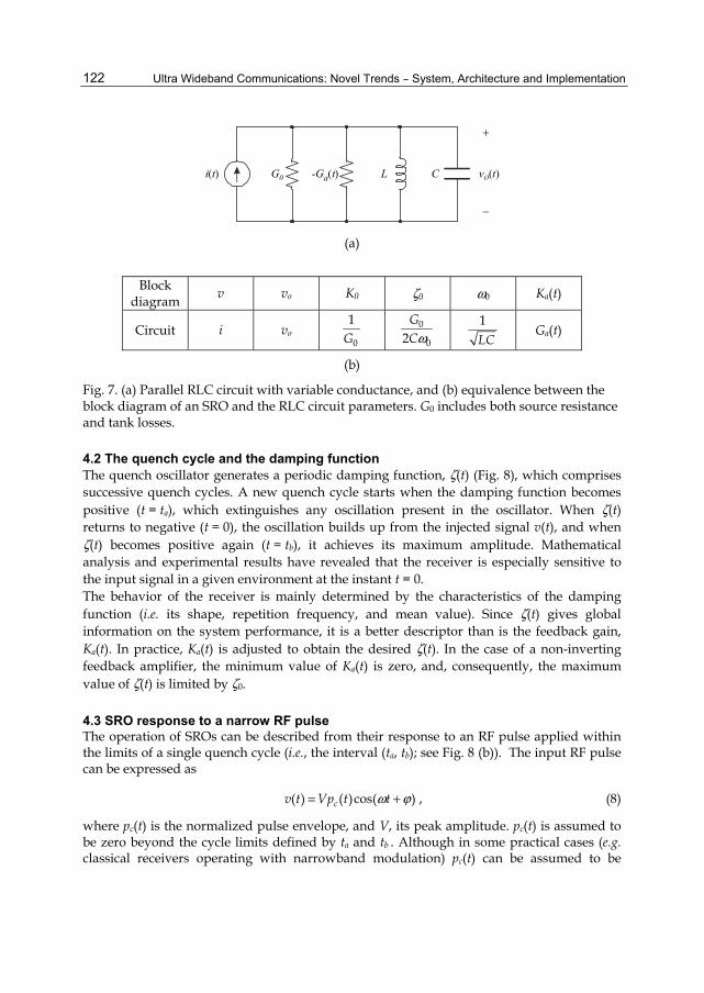
This function is very important, as it controls the overall performance of the receiver. By identifying the coefficients in the corresponding differential equations, one can obtain the equivalence between the parameters of the block diagram in Fig. 1 and those of a particular circuit. For example, Fig. 7 shows the equivalence for a parallel RLC circuit, a commonly used topology. In this case, the net conductance of the circuit is
0( ) ( )aG t G G t= $ , (6)
and the resulting damping function becomes
00 0
( ) 1( ) ( ( ))2 2 aG tt G G tC C
!" "
= = $ . (7)
Ultra Wideband Communications: Novel Trends �– System, Architecture and Implementation
122
-G ta( )G0 L C v tO( )i t( )
+
$
(a)
Block
diagram v vo K0 !0 "0 Ka(t)
Circuit i vo 0
1G
0
02GC"
1LC
Ga(t)
(b)
Fig. 7. (a) Parallel RLC circuit with variable conductance, and (b) equivalence between the block diagram of an SRO and the RLC circuit parameters. G0 includes both source resistance and tank losses.
4.2 The quench cycle and the damping function The quench oscillator generates a periodic damping function, !(t) (Fig. 8), which comprises successive quench cycles. A new quench cycle starts when the damping function becomes positive (t = ta), which extinguishes any oscillation present in the oscillator. When !(t) returns to negative (t = 0), the oscillation builds up from the injected signal v(t), and when !(t) becomes positive again (t = tb), it achieves its maximum amplitude. Mathematical analysis and experimental results have revealed that the receiver is especially sensitive to the input signal in a given environment at the instant t = 0. The behavior of the receiver is mainly determined by the characteristics of the damping function (i.e. its shape, repetition frequency, and mean value). Since !(t) gives global information on the system performance, it is a better descriptor than is the feedback gain, Ka(t). In practice, Ka(t) is adjusted to obtain the desired !(t). In the case of a non-inverting feedback amplifier, the minimum value of Ka(t) is zero, and, consequently, the maximum value of !(t) is limited by !0.
4.3 SRO response to a narrow RF pulse The operation of SROs can be described from their response to an RF pulse applied within the limits of a single quench cycle (i.e., the interval (ta, tb); see Fig. 8 (b)). The input RF pulse can be expressed as
( ) ( )cos( )cv t Vp t t" %= + , (8)
where pc(t) is the normalized pulse envelope, and V, its peak amplitude. pc(t) is assumed to be zero beyond the cycle limits defined by ta and tb . Although in some practical cases (e.g. classical receivers operating with narrowband modulation) pc(t) can be assumed to be
Ultra Wideband Impulse Radio Superregenerative Reception
123
constant and to represent a fraction of the input signal, in others (e.g. a UWB IR receiver), it may be a narrow pulse of relatively slow variation. The response of the SRO to the aforementioned input RF pulse is another RF pulse, described by
0( ) ( ) ( )cos( ( ))ov t VK H p t t H= " " + % + & " , (9)
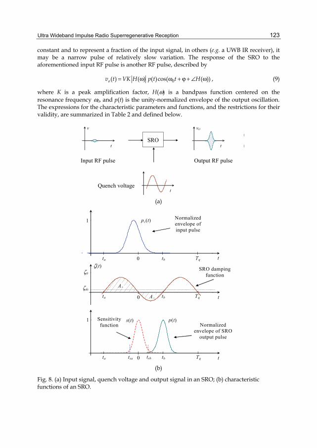
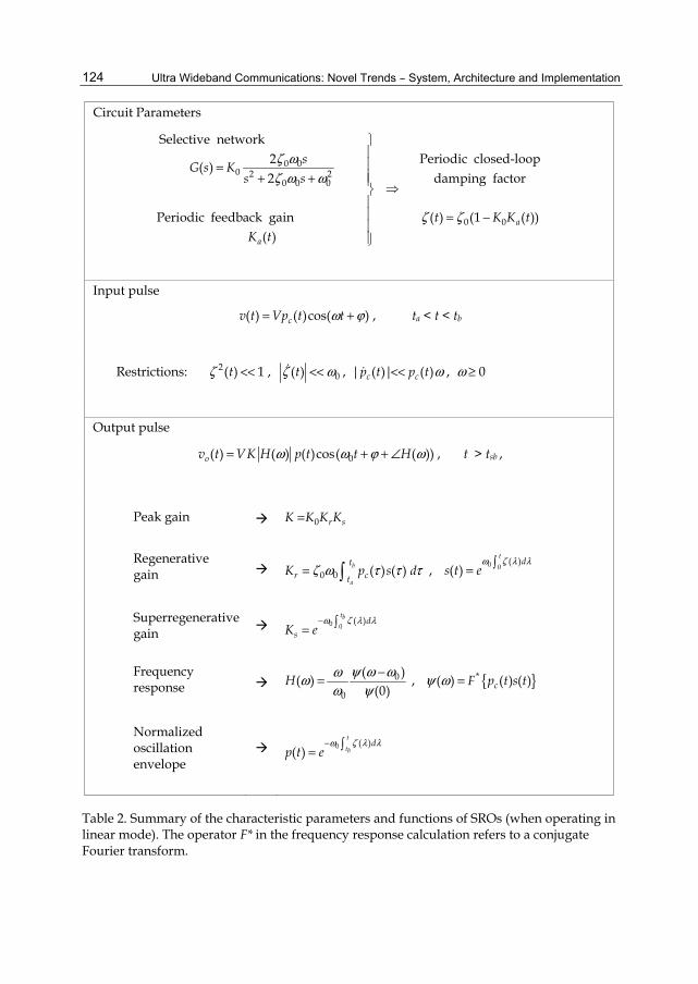
where K is a peak amplification factor, H(") is a bandpass function centered on the resonance frequency "0, and p(t) is the unity-normalized envelope of the output oscillation. The expressions for the characteristic parameters and functions, and the restrictions for their validity, are summarized in Table 2 and defined below.
Output RF pulse Input RF pulse
SRO t
vO
t
t
v
Quench voltage
(a)
pc(t)
s(t) p(t)
!(t)t
1
1
t
t
0
0
0
!dc
ta tbA$
A+
ta tb
Tq
Tq
Tqta tbtsa tsb
Normalized envelope of input pulse
SRO damping function
Normalized envelope of SRO
output pulse
Sensitivity function
!0
(b)
Fig. 8. (a) Input signal, quench voltage and output signal in an SRO; (b) characteristic functions of an SRO.
Ultra Wideband Communications: Novel Trends �– System, Architecture and Implementation
124
Circuit Parameters
0 00 2 2
0 0 0
0 0
Selective networkPeriodic closed-loop2( )
damping factor2
Periodic feedback gain ( ) (1 ( ))( )
a
a
sG s Ks s
t K K tK t
! "! " "
! !
=+ +
= $
Input pulse
( ) ( )cos( )cv t Vp t t" %= + , ta < t < tb
Restrictions: 2( ) 1t! << , 0( )t! "<< , | ( )| ( )c cp t p t "<< , " ' 0
Output pulse
0( ) ( ) ( )cos( ( ))ov t VK H p t t H" " % "= + + & , t > tsb ,
Peak gain 0 r sK K K K=
Regenerative gain 0 0 ( ) ( )b
a
tr ct
K p s d! " ( ( (= , 0 0( )
( )t
ds t e
" ! ) )=
Superregenerative gain 0 0
( )tb d
sK e" ! ) )$
=
Frequency response 0
0
( )( )(0)
H * " """" *
$= , { }*( ) ( ) ( )cF p t s t* " =
Normalized oscillation envelope
0 ( )( )
t
tbd
p t e" ! ) )$
=
Table 2. Summary of the characteristic parameters and functions of SROs (when operating in linear mode). The operator F* in the frequency response calculation refers to a conjugate Fourier transform.
Ultra Wideband Impulse Radio Superregenerative Reception
125
4.4 Characteristic parameters of SROs The parameters and functions shown in Table 2 are defined below: • Feedforward gain, (K0): is the gain that is provided by the selective network at the
resonance frequency, which equals the receiver gain when the feedback amplifier is inactive (open-loop situation).
• Sensitivity function (s(t)): a normalized function that describes the sampling process performed by the SRO. Its maximum value is one. Because this function is exponentially time-dependent, its value becomes quite small relatively close to the origin (t = 0). The shape of s(t) is determined mainly by the environment of the zero-crossing of !(t). A slow transition provides a wide curve, whereas a fast one yields a narrow curve. Both the regenerative gain and the frequency response depend on the product pc(t)s(t). Thus, the sensitivity curve acts as a function that weighs the incoming envelope pc(t): the values of pc(t) near t = 0 are considered, whereas those close to either ta or tb are irrelevant. Therefore, t = 0 represents the instant of maximum sensitivity.
• Regenerative gain (Kr): this gain depends on the product pc(t)s(t). If either pc(t) or s(t) is narrow, then Kr will be small; however, if both pc(t) and s(t) are wide, then Kr will be large.
• Superregenerative gain (Ks): this gain, associated with the exponential growth of the oscillation, is usually the most significant amplification factor. It is determined by the area enclosed by the negative portion of the damping function (Fig. 8 (b)).
• Frequency response (H(")): a bandpass function centered on "0 that is related to the complex conjugate of the Fourier transform of pc(t)s(t). If both pc(t) and s(t) are wide, then the reception bandwidth of the receiver will be small; however, if either pc(t) or s(t) is narrow, then this bandwidth will be large.
• Normalized oscillation envelope (p(t)): determined mainly by the evolution of the damping function close to t = tb . The same conclusions obtained for s(t) apply to p(t) in the environment of tb .
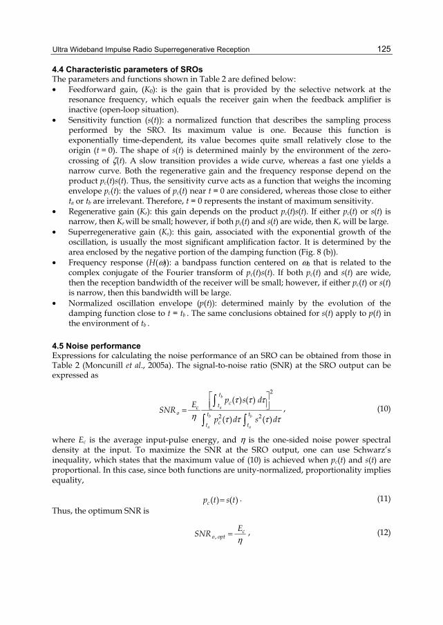
4.5 Noise performance Expressions for calculating the noise performance of an SRO can be obtained from those in Table 2 (Moncunill et al., 2005a). The signal-to-noise ratio (SNR) at the SRO output can be expressed as
2
2 2
( ) ( )
( ) ( )
b
a
b b
a a
tctc
o t tct t
p s dESNRp d s d
( ( (
+ ( ( ( (= , (10)
where Ec is the average input-pulse energy, and + is the one-sided noise power spectral density at the input. To maximize the SNR at the SRO output, one can use Schwarz�’s inequality, which states that the maximum value of (10) is achieved when pc(t) and s(t) are proportional. In this case, since both functions are unity-normalized, proportionality implies equality,
( ) ( )cp t s t= . (11) Thus, the optimum SNR is
,c
o optESNR+
= , (12)
Ultra Wideband Communications: Novel Trends �– System, Architecture and Implementation
126
which is that of a matched filter. This result is highly important, because the condition of a matched filter can be achieved in UWB IR SR receivers, but not in narrowband SR receivers. The optimum pulse envelope typically equals a Gaussian curve.
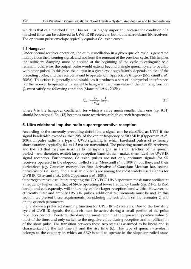
4.6 Hangover Under normal receiver operation, the output oscillation in a given quench cycle is generated mainly from the incoming signal, and not from the remnant of the previous cycle. This implies that sufficient damping must be applied at the beginning of the cycle to extinguish said remnant; otherwise, the output pulse would extend beyond a single quench cycle to overlap with other pulses. In this case, the output in a given cycle significantly depends on that of the preceding cycles, and the receiver is said to operate with appreciable hangover (Moncunill et al., 2005a). This effect is generally undesirable, as it produces a sort of intersymbol interference. For the receiver to operate with negligible hangover, the mean value of the damping function !dc must satisfy the following condition (Moncunill et al., 2005a):
0
1ln2
qdc
ff h
! >#
, (13)
where h is the hangover coefficient, for which a value much smaller than one (e.g. 0.01) should be assigned. Eq. (13) becomes more restrictive at high quench frequencies.
5. Ultra wideband impulse radio superregenerative reception According to the currently prevailing definition, a signal can be classified as UWB if the signal bandwidth exceeds either 20% of the center frequency or 500 MHz (Opperman et al., 2004). Impulse radio is a type of UWB signaling in which baseband pulses of extremely short duration (typically, 0.1 to 1.5 ns) are transmitted. The pulsating nature of SR receivers, and the fact that they are sensitive to the input signal in a small fraction of the quench period�—and therefore, exhibit large reception bandwidths�—makes them ideal for UWB IR signal reception. Furthermore, Gaussian pulses are not only optimum signals for SR receivers operated in the slope-controlled state (Moncunill et al., 2007a), but they, and their derivatives (e.g. Gaussian monopulse; first derivative of Gaussian; Mexican hat, second derivative of Gaussian; and Gaussian doublet) are among the most widely used signals for UWB IR (Ghavami et al., 2004; Opperman et al., 2004). Superregenerative oscillators targeting the FCC/ECC UWB spectrum mask must oscillate at a frequency higher than that of SROs operating at lower frequency bands (e.g. 2.4-GHz ISM band), and consequently, will inherently exhibit larger reception bandwidths. However, to efficiently filter and amplify UWB IR pulses, additional requirements must be met. In this section, we present these requirements, considering the restrictions on the resonator Q and on the quench parameters. Fig. 9 shows a preferred damping function for UWB IR SR receivers. Due to the low duty cycle of UWB IR signals, the quench must be active during a small portion of the pulse repetition period. Therefore, the damping must remain at the quiescent positive value !+ most of the time, and only switch to the negative value during reception and amplification of the short pulse. The transition between these two states is assumed to be linear and is characterized by the fall time (tf) and the rise time (tr). This type of quench waveform belongs to the category in which an SRO is said to operate in the slope-controlled state,
Ultra Wideband Impulse Radio Superregenerative Reception
127
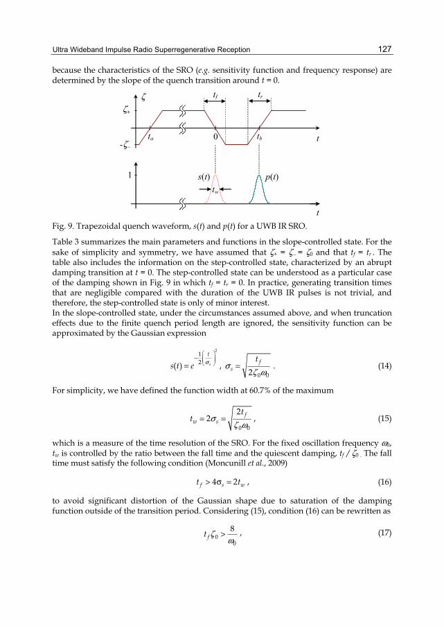
because the characteristics of the SRO (e.g. sensitivity function and frequency response) are determined by the slope of the quench transition around t = 0.
0 tb
t
t
! tf tr
tw
s(t) p(t)
!+
-!$ta
1
Fig. 9. Trapezoidal quench waveform, s(t) and p(t) for a UWB IR SRO.
Table 3 summarizes the main parameters and functions in the slope-controlled state. For the sake of simplicity and symmetry, we have assumed that !+ = !$ = !0 and that tf = tr . The table also includes the information on the step-controlled state, characterized by an abrupt damping transition at t = 0. The step-controlled state can be understood as a particular case of the damping shown in Fig. 9 in which tf = tr = 0. In practice, generating transition times that are negligible compared with the duration of the UWB IR pulses is not trivial, and therefore, the step-controlled state is only of minor interest. In the slope-controlled state, under the circumstances assumed above, and when truncation effects due to the finite quench period length are ignored, the sensitivity function can be approximated by the Gaussian expression
212( ) s
t
s t e ,$
= , 0 02f
st
,! "
= . (14)
For simplicity, we have defined the function width at 60.7% of the maximum
0 0
22 f
w st
t ,! "
= = , (15)
which is a measure of the time resolution of the SRO. For the fixed oscillation frequency "0, tw is controlled by the ratio between the fall time and the quiescent damping, tf / !0 . The fall time must satisfy the following condition (Moncunill et al., 2009)
4 2f s wt t> , = , (16)
to avoid significant distortion of the Gaussian shape due to saturation of the damping function outside of the transition period. Considering (15), condition (16) can be rewritten as
00
8ft !
"> , (17)
Ultra Wideband Communications: Novel Trends �– System, Architecture and Implementation
128
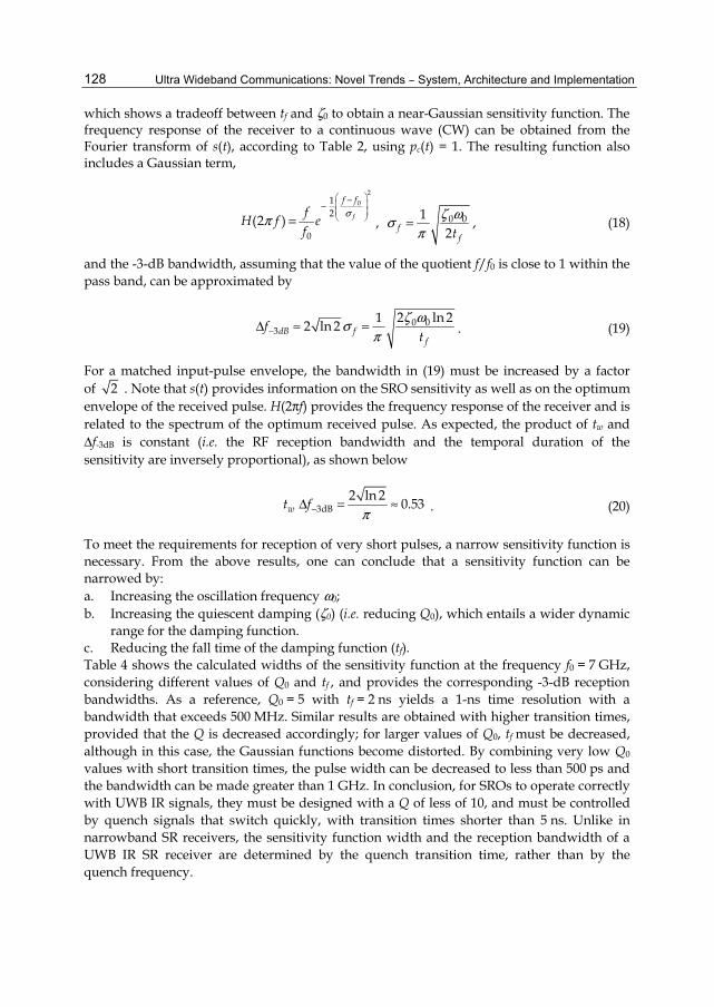
which shows a tradeoff between tf and !0 to obtain a near-Gaussian sensitivity function. The frequency response of the receiver to a continuous wave (CW) can be obtained from the Fourier transform of s(t), according to Table 2, using pc(t) = 1. The resulting function also includes a Gaussian term,
201
2
0(2 ) f
f ffH f ef
,#$$
= , 0 012f
ft! ",
#= , (18)
and the -3-dB bandwidth, assuming that the value of the quotient f/f0 is close to 1 within the pass band, can be approximated by
0 03
2 ln 212 ln 2dB ff
ft
! ",#$- . = . (19)
For a matched input-pulse envelope, the bandwidth in (19) must be increased by a factor of 2 . Note that s(t) provides information on the SRO sensitivity as well as on the optimum envelope of the received pulse. H(2#f) provides the frequency response of the receiver and is related to the spectrum of the optimum received pulse. As expected, the product of tw and -f-3dB is constant (i.e. the RF reception bandwidth and the temporal duration of the sensitivity are inversely proportional), as shown below
3dB2 ln 2 0.53wt f
#$- = . . (20)
To meet the requirements for reception of very short pulses, a narrow sensitivity function is necessary. From the above results, one can conclude that a sensitivity function can be narrowed by: a. Increasing the oscillation frequency "0; b. Increasing the quiescent damping (!0) (i.e. reducing Q0), which entails a wider dynamic
range for the damping function. c. Reducing the fall time of the damping function (tf). Table 4 shows the calculated widths of the sensitivity function at the frequency f0 = 7 GHz, considering different values of Q0 and tf , and provides the corresponding -3-dB reception bandwidths. As a reference, Q0 = 5 with tf = 2 ns yields a 1-ns time resolution with a bandwidth that exceeds 500 MHz. Similar results are obtained with higher transition times, provided that the Q is decreased accordingly; for larger values of Q0, tf must be decreased, although in this case, the Gaussian functions become distorted. By combining very low Q0 values with short transition times, the pulse width can be decreased to less than 500 ps and the bandwidth can be made greater than 1 GHz. In conclusion, for SROs to operate correctly with UWB IR signals, they must be designed with a Q of less of 10, and must be controlled by quench signals that switch quickly, with transition times shorter than 5 ns. Unlike in narrowband SR receivers, the sensitivity function width and the reception bandwidth of a UWB IR SR receiver are determined by the quench transition time, rather than by the quench frequency.

Ultra Wideband Impulse Radio Superregenerative Reception
129
Slope-controlled (tr = tf , tf > 2tw)
Step-controlled (tr = tf = 0)
s(t) (ta < t < tb) 2
0 0f
tte
! "$
0 0 te ! "$
p(t) (0 < t < Tq) 2
0 0( )b
f
t tte
! " $$
0 0 bt te ! "$ $
H(2#f) (CW) ( )22
00 0
0
ftf ff e
f
#! "
$ $
20
200
1
11 1
ff f
f!+ $
tw (60.7 %) 0 0
2 ft! "
0 0
1! "
-f-3dB 0 02 ln 21
ft! "
# 0 0 2 1! "
#$
Kr
Matched pulse Constant envelope pulse
0 0
2ft# ! "
0 0 ft# ! "
1 2
Ks 0 0 ( )2f
bt
te
! " $
0 0 bte! "
Table 3. Characteristic parameters and functions of an SRO with trapezoidal quench and !+ = !$ = !o.
Q0 !0 tf = 5 ns tf = 2 ns tf = 1 ns
tw
(ns) -f-3dB
(MHz) tw
(ns) -f-3dB
(MHz) tw
(ns) -f-3dB
(MHz) 10 0.05 2.13 249 1.35 * 393 * 0.95 * 556 * 5 0.1 1.51 352 0.95 556 0.67 * 785 *
2.5 0.2 1.07 ~ 500 0.67 785 0.48 1110
(*) These values may only be approximate, since the requirement tf > 2tw is not met in these cases.
Table 4. Sensitivity function width tw (= optimum received-pulse width) and -3-dB reception bandwidth -f-3dB (= optimum received-pulse bandwidth) at a frequency of 7 GHz for different values of Q0 and tf .
Ultra Wideband Communications: Novel Trends �– System, Architecture and Implementation
130
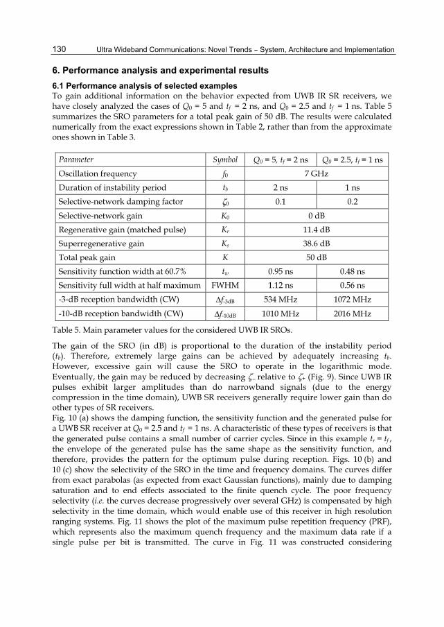
6. Performance analysis and experimental results 6.1 Performance analysis of selected examples To gain additional information on the behavior expected from UWB IR SR receivers, we have closely analyzed the cases of Q0 = 5 and tf = 2 ns, and Q0 = 2.5 and tf = 1 ns. Table 5 summarizes the SRO parameters for a total peak gain of 50 dB. The results were calculated numerically from the exact expressions shown in Table 2, rather than from the approximate ones shown in Table 3.
Parameter Symbol Q0 = 5, tf = 2 ns Q0 = 2.5, tf = 1 ns Oscillation frequency f0 7 GHz Duration of instability period tb 2 ns 1 ns Selective-network damping factor !0 0.1 0.2
Selective-network gain K0 0 dB Regenerative gain (matched pulse) Kr 11.4 dB Superregenerative gain Ks 38.6 dB Total peak gain K 50 dB Sensitivity function width at 60.7% tw 0.95 ns 0.48 ns Sensitivity full width at half maximum FWHM 1.12 ns 0.56 ns -3-dB reception bandwidth (CW) -f-3dB 534 MHz 1072 MHz
-10-dB reception bandwidth (CW) -f-10dB 1010 MHz 2016 MHz
Table 5. Main parameter values for the considered UWB IR SROs.
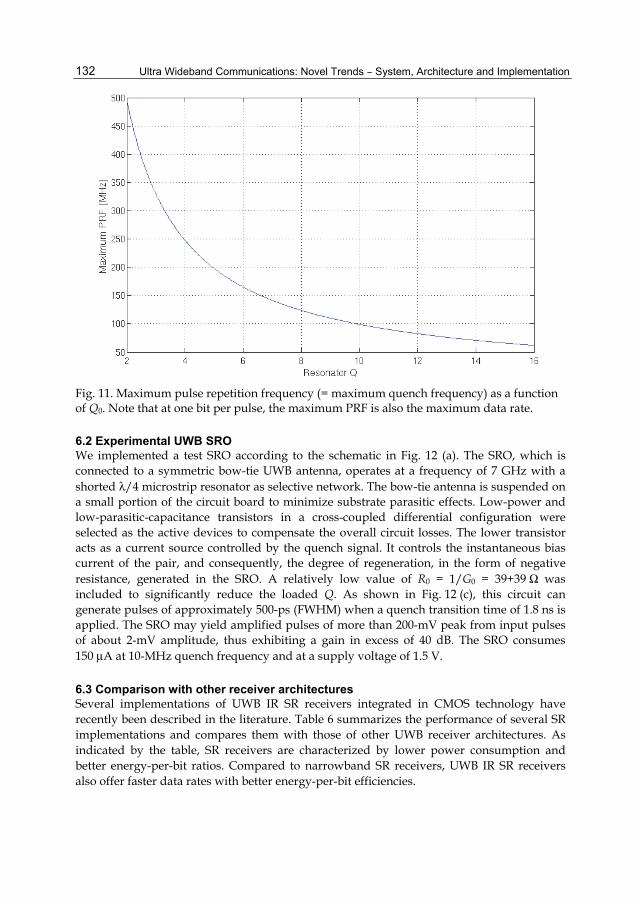
The gain of the SRO (in dB) is proportional to the duration of the instability period (tb). Therefore, extremely large gains can be achieved by adequately increasing tb. However, excessive gain will cause the SRO to operate in the logarithmic mode. Eventually, the gain may be reduced by decreasing !$ relative to !+ (Fig. 9). Since UWB IR pulses exhibit larger amplitudes than do narrowband signals (due to the energy compression in the time domain), UWB SR receivers generally require lower gain than do other types of SR receivers. Fig. 10 (a) shows the damping function, the sensitivity function and the generated pulse for a UWB SR receiver at Q0 = 2.5 and tf = 1 ns. A characteristic of these types of receivers is that the generated pulse contains a small number of carrier cycles. Since in this example tr = tf , the envelope of the generated pulse has the same shape as the sensitivity function, and therefore, provides the pattern for the optimum pulse during reception. Figs. 10 (b) and 10 (c) show the selectivity of the SRO in the time and frequency domains. The curves differ from exact parabolas (as expected from exact Gaussian functions), mainly due to damping saturation and to end effects associated to the finite quench cycle. The poor frequency selectivity (i.e. the curves decrease progressively over several GHz) is compensated by high selectivity in the time domain, which would enable use of this receiver in high resolution ranging systems. Fig. 11 shows the plot of the maximum pulse repetition frequency (PRF), which represents also the maximum quench frequency and the maximum data rate if a single pulse per bit is transmitted. The curve in Fig. 11 was constructed considering

Ultra Wideband Impulse Radio Superregenerative Reception
131
hangover limitations (Eq. (13)) and reveals that data rates faster than 200 Mbps are available for low-Q-resonator SR receivers.
(a)
(b)
(c)
Fig. 10. (a) Damping function, sensitivity function and normalized output pulse at f0 = 7 GHz. Selectivity curves (b) in the time domain and (c) in the frequency domain.
Q0 = 5 tf = 2 ns
Q0 = 2.5 tf = 1 ns
Q0 = 5 tf = 2 ns
Q0 = 2.5 tf = 1 ns
Q0 = 2.5 tf = 1 ns
Q0 = 2.5 tf = 1 ns
Ultra Wideband Communications: Novel Trends �– System, Architecture and Implementation
132
Fig. 11. Maximum pulse repetition frequency (= maximum quench frequency) as a function of Q0. Note that at one bit per pulse, the maximum PRF is also the maximum data rate.
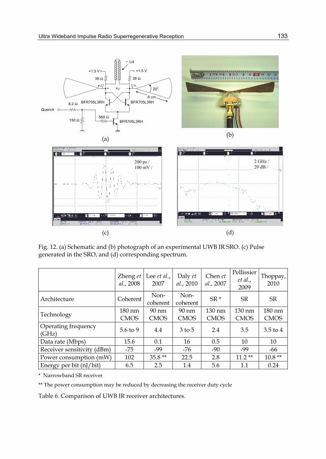
6.2 Experimental UWB SRO We implemented a test SRO according to the schematic in Fig. 12 (a). The SRO, which is connected to a symmetric bow-tie UWB antenna, operates at a frequency of 7 GHz with a shorted )/4 microstrip resonator as selective network. The bow-tie antenna is suspended on a small portion of the circuit board to minimize substrate parasitic effects. Low-power and low-parasitic-capacitance transistors in a cross-coupled differential configuration were selected as the active devices to compensate the overall circuit losses. The lower transistor acts as a current source controlled by the quench signal. It controls the instantaneous bias current of the pair, and consequently, the degree of regeneration, in the form of negative resistance, generated in the SRO. A relatively low value of R0 = 1/G0 = 39+39 / was included to significantly reduce the loaded Q. As shown in Fig. 12 (c), this circuit can generate pulses of approximately 500-ps (FWHM) when a quench transition time of 1.8 ns is applied. The SRO may yield amplified pulses of more than 200-mV peak from input pulses of about 2-mV amplitude, thus exhibiting a gain in excess of 40 dB. The SRO consumes 150 µA at 10-MHz quench frequency and at a supply voltage of 1.5 V.
6.3 Comparison with other receiver architectures Several implementations of UWB IR SR receivers integrated in CMOS technology have recently been described in the literature. Table 6 summarizes the performance of several SR implementations and compares them with those of other UWB receiver architectures. As indicated by the table, SR receivers are characterized by lower power consumption and better energy-per-bit ratios. Compared to narrowband SR receivers, UWB IR SR receivers also offer faster data rates with better energy-per-bit efficiencies.
Ultra Wideband Impulse Radio Superregenerative Reception
133
6 cm
560 /
39 /
+1.5 V
Quench
BFR705L3RH
BFR705L3RH
v-v+
39 /
8.2 /
150 /
20o
BFR705L3RH
vO+ $
+1.5 V
~ )/4
(a)
(b)
(c)
(d)
Fig. 12. (a) Schematic and (b) photograph of an experimental UWB IR SRO. (c) Pulse generated in the SRO, and (d) corresponding spectrum.
Zheng et al., 2008
Lee et al., 2007
Daly et al., 2010
Chen et al., 2007
Pellissier et al., 2009
Thoppay, 2010
Architecture Coherent Non- coherent
Non- coherent SR * SR SR
Technology 180 nm CMOS
90 nm CMOS
90 nm CMOS
130 nm CMOS
130 nm CMOS
180 nm CMOS
Operating frequency (GHz) 5.6 to 9 4.4 3 to 5 2.4 3.5 3.5 to 4
Data rate (Mbps) 15.6 0.1 16 0.5 10 10 Receiver sensitivity (dBm) -75 -99 -76 -90 -99 -66 Power consumption (mW) 102 35.8 ** 22.5 2.8 11.2 ** 10.8 ** Energy per bit (nJ/bit) 6.5 2.5 1.4 5.6 1.1 0.24
* Narrowband SR receiver
** The power consumption may be reduced by decreasing the receiver duty cycle
Table 6. Comparison of UWB IR receiver architectures.
200 ps / 100 mV /
2 GHz / 20 dB /
Ultra Wideband Communications: Novel Trends �– System, Architecture and Implementation
134
7. Conclusions In this chapter, we have demonstrated that SR receivers are a promising, low-power and low-cost alternative for UWB IR communications. The relatively short sensitivity periods of SROs makes them ideal for reception of short RF pulses in general, and of UWB IR in particular. Proper pulse reception requires implementation of a quench synchronization mechanism. Although synchronous operation generally leads to more complex receivers, it offers myriad advantages. For example, the receiver may operate as a matched filter, achieving improved noise and interference rejection; faster data rates become accessible; and energy efficiency can be improved. We have shown that to achieve efficient filtering and amplification of UWB IR signals, low-Q (< 10) superregenerative oscillators must be designed, and that quench signals with short switching times (< 5 ns) must be applied. Theoretical and experimental results show that an optimized design can efficiently process sub-500-ps pulses, achieving peak gains in excess of 40 dB and reception bandwidths at -3-dB above 1 GHz. Furthermore, in a UWB IR SR receiver, the data transfer rate may be maximized by generating a single quench period per received bit. This implies that the quench generator must operate with a quench frequency equal to the data rate. Taking into account hangover effects, which set an upper bound for the quench frequency, we have predicted data transfer rates faster than 200 Mbps for very low-Q SROs. The power consumption of implemented UWB IR SR receivers are among the lowest ever reported, with efficiencies less than 500 pJ/bit at data rates of roughly 10 Mbps.
8. References Anis, M.; Tielert, R. & Wehn, N. (2008). Super-regenerative UWB impulse detector with
synchronized quenching mechanism, Proceedings of ESSCIRC 2008 34th European Solid-State Circuits Conference, pp. 390-393, ISSN 1930-8833, Edinburgh, Scotland, UK, September 15-19, 2008
Armstrong, E. H. (1922). Some recent developments of regenerative circuits. Proc. IRE, Vol. 10, (August 1922), pp. 244-260, ISSN 0731-5996
Ayers, J.; Mayaram, K. & Fiez, T. S. (2010). An ultra low-power receiver for wireless sensor networks. IEEE Journal of Solid-State Circuits, Vol. 45 , No. 9 (August 2010). pp. 1759 �– 1769, ISSN 0018-9200
Bohorquez, J. L.; Chandrakasan, A.P. & Dawson, J. L. (2009). A 350µW CMOS MSK Transmitter and 400µW OOK Super-Regenerative Receiver for Medical Implant Communications. IEEE Journal of Solid-State Circuits, Vol. 44 , No. 4, (March 2009), pp. 1248 �– 1259, ISSN 0018-9200
Chen, J. Y.; Flynn, M. P. & Hayes, J. P. (2007). A fully integrated auto-calibrated super-regenerative receiver in 0.13-µm CMOS; IEEE Journal of Solid-State Circuits, Vol. 42 , No. 9, (September 2007), pp. 1976 �– 1985, ISSN 0018-9200
Daly, D. C.; Mercier, P. P.; Bhardwaj, M.; Stone, A. L.; Aldworth, Z. N.; Daniel, T. L.; Voldman, J.; Hildebrand, J. G. & Chandrakasan, A. P. (2010). A Pulsed UWB Receiver SoC for Insect Motion Control. IEEE Journal of Solid-State Circuits, Vol. 45, No. 1, (January 2010), pp. 153 �– 166, ISSN 0018-9200
España-Boquera, M. C. & A. Puerta-Notario, A. (1999). Bit-error rate and frequency response in superregenerative semiconductor laser receivers. Optics Letters, Vol. 24, No. 3, (February 1999), pp. 157-159, ISSN 0146-9592
Ultra Wideband Impulse Radio Superregenerative Reception
135
Favre, P.; Joehl, N.; Vouilloz, A.; Deval, P.; Dehollain, C. & Declercq, M. J. (1998). A 2-V 600-µA 1-GHz BiCMOS super-regenerative receiver for ISM applications. IEEE Jour. of Solid-State Circ., Vol. 33 , No. 12, (December 2008), pp. 2186 �– 2196, ISSN 0018-9200
Ghavami, M.; Michael, L. B. & Kohno, R. (2004). Ultra Wideband Signals and Systems in Comm. Engineering, John Wiley & Sons, ISBN 0-470-86751-5, West Sussex, England
Hickman, I. (2002). Practical RF Handbook (3rd ed.). Newnes, ISBN 0 7506 5369 8, Oxford Lee, F.S. & Chandrakasan, A.P. (2007). A 2.5 nJ/bit 0.65 V pulsed UWB receiver in 90 nm
CMOS. IEEE Journal of Solid-State Circuits, Vol. 42, No. 12, (November 2007), pp. 2851 �– 2859, ISSN : 0018-9200
Levanon, N.; Stremler, F. G. & Suomi, V.E. (1974). A new approach to lightweight radar altimeters. Proceedings of the IEEE, Vol. 62 , No. 6, (June 1974), pp. 784 �– 792, ISSN 0018-9219
McCoy, W.G. (1992). Design of a superregenerative receiver for solar powered applications. IEEE Transactions on Consumer Electronics, Vol. 38, No. 4, (November 1992), pp. 869-873, ISSN 0098-3063
Milner C. J. & Shell, G. S. (1968). A super-regenerative microwave Doppler moving-target indicator. IEEE Transactions on Vehicular Technology, Vol. vt-17, No. 1, (October 1968), pp. 13-23, ISSN 0018-9545
Moncunill-Geniz, F. X.; Palà-Schönwälder, P. & Mas-Casals, O. (2005a). A generic approach to the theory of superregenerative reception. IEEE Transactions on Circuits and Systems I: Regular Papers, Vol. 52 , No. 1, (January 2005), pp. 54 �– 70, ISSN 1549-8328
Moncunill-Geniz, F. X.; Palà-Schönwälder, P. & del Aguila-Lopez, F. (2005b). New superregenerative architectures for direct-sequence spread-spectrum communications. IEEE Transactions on Circuits and Systems II: Express Briefs, Vol. 52, No. 7, (July 2005), pp. 415 �– 419, ISSN 1549-7747
Moncunill-Geniz, F. X.; Palà-Schönwälder, P.; Dehollain, C.; Joehl, N. & Declercq, M. (2005c). A 2.4-GHz DSSS superregenerative receiver with a simple delay-locked loop. IEEE Microwave and Wireless Components Letters, Vol. 15 , No. 8, (August 2005), pp. 499 �– 501, ISSN 1531-1309
Moncunill-Geniz, F. X.; Palà-Schönwälder, P.; Dehollain, C.; Joehl, N. & Declercq, M. (2007a). An 11-Mb/s 2.1-mW Synchronous Superregenerative Receiver at 2.4 GHz. IEEE Transactions on Microwave Theory and Techniques, Vol. 55, No 6, Part 2, (June 2007), pp. 1355 �– 1362, ISSN 0018-9480
Moncunill-Geniz, F. X.; Palà-Schönwälder, P.; del Àguila-Lopez, F. & Giralt-Mas, R. (2007b). Application of the superregenerative principle to UWB pulse generation and reception. Proceedings of the 14th IEEE International Conference on Electronics, Circuits and Systems, 2007, pp. 935 �– 938, ISBN 978-1-4244-1377-5, Marrakech, Morocco, December 11, 2007
Moncunill-Geniz, F. X.; Pala-Schonwalder, P.; Bonet-Dalmau, J.; del Aguila-Lopez, F. & Giralt-Mas, R. (2009). Sub-nanosecond pulse filtering and amplification through first-order controlled circuit instability. Proc. of the 39th European Microwave Conf., 2009, pp. 1319 �– 1322, ISBN: 978-1-4244-4748-0, Rome, Italy, September 29, 2009
Opperman, I.; Hämäläinen, M. & Ianatti, J. (2004). UWB Theory and Applications, John Wiley & Sons, ISBN 0-470-86917-8, West Sussex, England
Otis, B.; Chee, Y. H. & Rabaey, J. (2005). A 400µW-RX, 1.6mW-TX super-regenerative transceiver for wireless sensor networks. 2005 IEEE International Solid-State Circuits
Ultra Wideband Communications: Novel Trends �– System, Architecture and Implementation
136
Conference, 2005, Digest of Technical Papers, Vol. 1, pp. 396 �– 606, ISSN 0193-6530, San Francisco, CA, February 10, 2005
Palà-Schönwälder, P.; Moncunill-Geniz, F. X.; Bonet-Dalmau, J.; del-Aguila-Lopez, F. & Giralt-Mas, R. (2009). A BPSK superregenerative receiver. Preliminary results. Proceedings of the IEEE International Symposium on Circuits and Systems, pp. 1537 �– 1540, ISBN 978-1-4244-3827-3, Taipei, Taiwan, June 26, 2009
Pelissier, M.; Morche, D. & Vincent, P. (2009). Super-regenerative architecture for UWB pulse detection: from theory to RF front-end design. IEEE Transactions on Circuits and Systems I, Vol. 56, No. 7, (July 2009), pp. 1500-1512, ISSN 1549-8328
Telecontrolli Srl, 15.03.2011, Available from http://www.telecontrolli.com Thoppay, P. (2010). A low power super-regenerative impulse radio ultra-wideband receiver in
CMOS technology, Ph.D. Dissertation, EPFL, Lausanne, Switzerland Whitehead, J. R. (1950). Super-Regenerative Receivers, Cambridge Univ. Press, Cambridge, UK Zheng, Y.; Annamalai Arasu, M.; Wong, K.-W.; The, Y. J.; Suan, A.-P.-H.; Tran, D.-D.; Yeoh,
W.-G. & Kwong, D.-L. (2008). A 0.18 m CMOS 802.15.4a UWB Transceiver for Communication and Localization. 2008 IEEE International Solid-State Circuits Conference, 2008, Digest of Technical Papers, pp. 118 �– 600, ISBN 978-1-4244-2010-0, San Francisco, CA, February 3, 2008