ultra enterprise 3000 system manual - oracle · 6.3.1 troubleshooting a peripheral power supply. ....
TRANSCRIPT

Ultra™ Enterprise™ 3000 System Manual
Part No.: 802-6051-10Revision A, May 1996
The Network Is the Computer™
Sun Microsystems Computer Company2550 Garcia AvenueMountain View, CA 94043 USA415 960-1300 fax 415 969-9131

PleaseRecycle
Copyright 1996 Sun Microsystems, Inc. 2550 Garcia Avenue, Mountain View, California 94043-1100 U.S.A.
All rights reserved. This product or document is protected by copyright and distributed under licenses restricting its use, copying, distribution,and decompilation. No part of this product or document may be reproduced in any form by any means without prior written authorization ofSun and its licensors, if any.
Portions of this product may be derived from the UNIX® system and from the Berkeley 4.3 BSD system, licensed from the University ofCalifornia. UNIX is a registered trademark in the United States and in other countries and is exclusively licensed by X/Open Company Ltd.Third-party software, including font technology in this product, is protected by copyright and licensed from Sun’s suppliers.
RESTRICTED RIGHTS LEGEND: Use, duplication, or disclosure by the government is subject to restrictions as set forth in subparagraph (c)(1)(ii)of the Rights in Technical Data and Computer Software clause at DFARS 252.227-7013 and FAR 52.227-19.
Sun, Sun Microsystems, the Sun logo, Solaris, Solstice, SyMON, OpenBoot, Enterprise, SunVTS, Ultra, UltraComputing, UltraServer, andUltraSPARC are trademarks or registered trademarks of Sun Microsystems, Inc. in the United States and in other countries. All SPARCtrademarks are used under license and are trademarks or registered trademarks of SPARC International, Inc. in the United States and in othercountries. Products bearing SPARC trademarks are based upon an architecture developed by Sun Microsystems, Inc.
The OPEN LOOK® and Sun™ Graphical User Interfaces were developed by Sun Microsystems, Inc. for its users and licensees. Sunacknowledges the pioneering efforts of Xerox Corporation in researching and developing the concept of visual or graphical user interfaces for thecomputer industry. Sun holds a nonexclusive license from Xerox to the Xerox Graphical User Interface, which license also covers Sun’s licenseeswho implement OPEN LOOK GUIs and otherwise comply with Sun’s written license agreements.
X Window System is a trademark of X Consortium, Inc.
THIS PUBLICATION IS PROVIDED “AS IS” WITHOUT WARRANTY OF ANY KIND, EITHER EXPRESS OR IMPLIED, INCLUDING,BUT NOT LIMITED TO, THE IMPLIED WARRANTIES OF MERCHANTABILITY, FITNESS FOR A PARTICULAR PURPOSE, ORNON-INFRINGEMENT.
Copyright 1996 Sun Microsystems, Inc., 2550 Garcia Avenue, Mountain View, Californie 94043-1100 U.S.A.
Tous droits réservés. Ce produit ou document est protégé par un copyright et distribué avec des licences qui en restreignent l’utilisation, la copieet la décompilation. Aucune partie de ce produit ou de sa documentation associée ne peut être reproduite sous aucune forme, par quelque moyenque ce soit, sans l’autorisation préalable et écrite de Sun et de ses bailleurs de licence, s’il y en a.
Des parties de ce produit pourront être derivées du système UNIX® et du système Berkeley 4.3 BSD licencié par l’Université de Californie. UNIXest une marque enregistrée aux Etats-Unis et dans d’autres pays, et licenciée exclusivement par X/Open Company Ltd. Le logiciel détenu par destiers, et qui comprend la technologie relative aux polices de caractères, est protégé par un copyright et licencié par des fournisseurs de Sun.
Sun, Sun Microsystems, le logo Sun, Solaris, Solstice, SyMON, OpenBoot, Enterprise, SunVTS, Ultra, UltraComputing, UltraServer, etUltraSPARC sont des marques déposées ou enregistrées de Sun Microsystems, Inc. aux Etats-Unis et dans d’autres pays. Toutes les marquesSPARC, utilisées sous licence, sont des marques déposées ou enregistrées de SPARC International, Inc. aux Etats-Unis et dans d’autres pays. Lesproduits portant les marques SPARC sont basés sur une architecture développée par Sun Microsystems, Inc.
Les utilisateurs d’interfaces graphiques OPEN LOOK® et Sun™ ont été développés de Sun Microsystems, Inc. pour ses utilisateurs et licenciés.Sun reconnaît les efforts de pionniers de Xerox Corporation pour la recherche et le développement du concept des interfaces d’utilisation visuelleou graphique pour l’industrie de l’informatique. Sun détient une licence non exclusive de Xerox sur l’interface d’utilisation graphique, cettelicence couvrant aussi les licenciés de Sun qui mettent en place les utilisateurs d’interfaces graphiques OPEN LOOK et qui en outre seconforment aux licences écrites de Sun.
Le système X Window est un produit du X Consortium, Inc.
CETTE PUBLICATION EST FOURNIE "EN L’ETAT" SANS GARANTIE D’AUCUNE SORTE, NI EXPRESSE NI IMPLICITE, Y COMPRIS, ETSANS QUE CETTE LISTE NE SOIT LIMITATIVE, DES GARANTIES CONCERNANT LA VALEUR MARCHANDE, L’APTITUDE DESPRODUITS A REPONDRE A UNE UTILISATION PARTICULIERE OU LE FAIT QU’ILS NE SOIENT PAS CONTREFAISANTS DE PRODUITSDE TIERS.

iii
Contents
Part 1—Product Description
1. Product Overview . . . . . . . . . . . . . . . . . . . . . . . . . . . . . . . . . . . . . 1-1
1.1 Standard Features. . . . . . . . . . . . . . . . . . . . . . . . . . . . . . . . . 1-1
1.2 Internal Options . . . . . . . . . . . . . . . . . . . . . . . . . . . . . . . . . . 1-3
2. Safety Precautions and Tools Requirements . . . . . . . . . . . . . . 2-1
2.1 Safety Precautions . . . . . . . . . . . . . . . . . . . . . . . . . . . . . . . . 2-1
2.2 Symbols . . . . . . . . . . . . . . . . . . . . . . . . . . . . . . . . . . . . . . . . . 2-2
2.3 Tools Required . . . . . . . . . . . . . . . . . . . . . . . . . . . . . . . . . . . 2-4
Part 2—System Components
3. CPU/Memory Boards and Components . . . . . . . . . . . . . . . . . . 3-1
3.1 Handling Boards and Assemblies . . . . . . . . . . . . . . . . . . . 3-2
3.2 Filler Panels . . . . . . . . . . . . . . . . . . . . . . . . . . . . . . . . . . . . . . 3-2
3.3 Hot-Plug Feature . . . . . . . . . . . . . . . . . . . . . . . . . . . . . . . . . 3-3
3.4 CPU/Memory Boards . . . . . . . . . . . . . . . . . . . . . . . . . . . . . 3-4
3.4.1 Removing a Board. . . . . . . . . . . . . . . . . . . . . . . . . . . . 3-5

iv Ultra Enterprise 3000 System Manual—May 1996
3.4.2 Installing a Board . . . . . . . . . . . . . . . . . . . . . . . . . . . . 3-8
3.4.3 UltraSPARC Modules . . . . . . . . . . . . . . . . . . . . . . . . . 3-10
3.4.4 Handling Precautions . . . . . . . . . . . . . . . . . . . . . . . . . 3-10
3.4.5 Memory Modules (SIMMs) . . . . . . . . . . . . . . . . . . . . 3-15
4. I/O Boards and Components . . . . . . . . . . . . . . . . . . . . . . . . . . . . 4-1
4.1 Handling Boards and Assemblies . . . . . . . . . . . . . . . . . . . 4-2
4.2 Filler Panels . . . . . . . . . . . . . . . . . . . . . . . . . . . . . . . . . . . . . . 4-2
4.3 SCSI Termination . . . . . . . . . . . . . . . . . . . . . . . . . . . . . . . . . 4-3
4.4 Hot-Plug Feature . . . . . . . . . . . . . . . . . . . . . . . . . . . . . . . . . 4-4
4.5 I/O Boards. . . . . . . . . . . . . . . . . . . . . . . . . . . . . . . . . . . . . . . 4-4
4.5.1 tpe-link-test? Variable . . . . . . . . . . . . . . . . . . . . 4-5
4.5.2 Removing a Board. . . . . . . . . . . . . . . . . . . . . . . . . . . . 4-10
4.5.3 Installing a Board . . . . . . . . . . . . . . . . . . . . . . . . . . . . 4-13
4.5.4 SBus Cards . . . . . . . . . . . . . . . . . . . . . . . . . . . . . . . . . . 4-15
4.5.5 Graphics (UPA) Cards . . . . . . . . . . . . . . . . . . . . . . . . 4-23
4.5.6 Fibre Cards. . . . . . . . . . . . . . . . . . . . . . . . . . . . . . . . . . 4-27
5. Clock Board . . . . . . . . . . . . . . . . . . . . . . . . . . . . . . . . . . . . . . . . . . 5-1
5.1 Handling Boards and Assemblies . . . . . . . . . . . . . . . . . . . 5-2
5.2 Clock Board . . . . . . . . . . . . . . . . . . . . . . . . . . . . . . . . . . . . . . 5-2
5.2.1 ConsoleBus. . . . . . . . . . . . . . . . . . . . . . . . . . . . . . . . . . 5-5
5.2.2 Clocks . . . . . . . . . . . . . . . . . . . . . . . . . . . . . . . . . . . . . . 5-5
5.2.3 Reset logic . . . . . . . . . . . . . . . . . . . . . . . . . . . . . . . . . . 5-5
5.2.4 Removing a Clock Board . . . . . . . . . . . . . . . . . . . . . . 5-6
5.2.5 Installing a Clock Board . . . . . . . . . . . . . . . . . . . . . . . 5-7
Contents v
6. Power Supplies . . . . . . . . . . . . . . . . . . . . . . . . . . . . . . . . . . . . . . . 6-1
6.1 Safety Precautions . . . . . . . . . . . . . . . . . . . . . . . . . . . . . . . . 6-3
6.2 Distribution . . . . . . . . . . . . . . . . . . . . . . . . . . . . . . . . . . . . . . 6-3
6.3 Peripheral Power Supply. . . . . . . . . . . . . . . . . . . . . . . . . . . 6-3
6.3.1 Troubleshooting a Peripheral Power Supply. . . . . . 6-4
6.3.2 Replacing a Peripheral Power Supply . . . . . . . . . . . 6-5
6.4 Power/Cooling Module (PCM) . . . . . . . . . . . . . . . . . . . . . 6-8
6.4.1 Power Requirements. . . . . . . . . . . . . . . . . . . . . . . . . . 6-8
6.4.2 Cooling Requirements . . . . . . . . . . . . . . . . . . . . . . . . 6-9
6.4.3 Troubleshooting a PCM . . . . . . . . . . . . . . . . . . . . . . . 6-9
6.4.4 Replacing a PCM. . . . . . . . . . . . . . . . . . . . . . . . . . . . . 6-10
7. Internal SCSI and Storage Devices . . . . . . . . . . . . . . . . . . . . . . 7-1
7.1 Tape and CD-ROM Drive . . . . . . . . . . . . . . . . . . . . . . . . . . 7-2
7.1.1 Use and Maintenance . . . . . . . . . . . . . . . . . . . . . . . . . 7-2
7.1.2 Removing/Replacing a Tape or CD-ROM Drive . . 7-3
7.2 Disk Drives . . . . . . . . . . . . . . . . . . . . . . . . . . . . . . . . . . . . . . 7-5
7.2.1 Use and Maintenance . . . . . . . . . . . . . . . . . . . . . . . . . 7-5
7.2.2 Removing a Disk Drive . . . . . . . . . . . . . . . . . . . . . . . 7-6
7.2.3 Installing a Disk Drive . . . . . . . . . . . . . . . . . . . . . . . . 7-9
Part 3—Troubleshooting
8. Troubleshooting Overview . . . . . . . . . . . . . . . . . . . . . . . . . . . . . 8-1
8.1 Using a Terminal. . . . . . . . . . . . . . . . . . . . . . . . . . . . . . . . . . 8-1
8.2 Reset Switches. . . . . . . . . . . . . . . . . . . . . . . . . . . . . . . . . . . . 8-2
8.3 Hardware Indicators . . . . . . . . . . . . . . . . . . . . . . . . . . . . . . 8-3
vi Ultra Enterprise 3000 System Manual—May 1996
8.3.1 Clock Board LEDs . . . . . . . . . . . . . . . . . . . . . . . . . . . . 8-4
8.3.2 CPU/Memory and I/O Board LEDs . . . . . . . . . . . . 8-4
8.3.3 Power Supplies . . . . . . . . . . . . . . . . . . . . . . . . . . . . . . 8-6
8.3.4 Disk Tray Indicators . . . . . . . . . . . . . . . . . . . . . . . . . . 8-7
8.4 Card Cage Slot Information . . . . . . . . . . . . . . . . . . . . . . . . 8-7
8.5 Diagnosing Problems and Taking Action . . . . . . . . . . . . . 8-8
8.5.1 Servicing Obvious Problems . . . . . . . . . . . . . . . . . . . 8-8
8.5.2 Troubleshooting Less Obvious Problems. . . . . . . . . 8-8
8.5.3 POST and OpenBoot . . . . . . . . . . . . . . . . . . . . . . . . . . 8-10
8.5.4 Solstice SyMON. . . . . . . . . . . . . . . . . . . . . . . . . . . . . . 8-11
8.6 Specific Problems and Solutions . . . . . . . . . . . . . . . . . . . . . 8-12
8.6.1 Failure of Network Communications . . . . . . . . . . . . 8-12
8.6.2 Using a Remote Console . . . . . . . . . . . . . . . . . . . . . . 8-13
9. Flow Diagrams for Troubleshooting . . . . . . . . . . . . . . . . . . . . . 9-1
9.1 No AC/DC Power . . . . . . . . . . . . . . . . . . . . . . . . . . . . . . . . 9-2
9.2 System Cannot Boot . . . . . . . . . . . . . . . . . . . . . . . . . . . . . . . 9-3
9.3 Defective CPU/Memory Board . . . . . . . . . . . . . . . . . . . . . 9-4
9.4 Defective I/O Interface Board. . . . . . . . . . . . . . . . . . . . . . . 9-5
9.5 Defective Disk Drive . . . . . . . . . . . . . . . . . . . . . . . . . . . . . . 9-6
9.6 Defective Power Supplies . . . . . . . . . . . . . . . . . . . . . . . . . . 9-7
9.7 Defective Clock Board . . . . . . . . . . . . . . . . . . . . . . . . . . . . . 9-8
Part 4—Service Information
10. Safety and Tools . . . . . . . . . . . . . . . . . . . . . . . . . . . . . . . . . . . . . . 10-1
10.1 Safety Precautions . . . . . . . . . . . . . . . . . . . . . . . . . . . . . . . . 10-1

Contents vii
10.2 Symbols . . . . . . . . . . . . . . . . . . . . . . . . . . . . . . . . . . . . . . . . . 10-2
10.3 System Precautions. . . . . . . . . . . . . . . . . . . . . . . . . . . . . . . . 10-4
10.4 Tools Required . . . . . . . . . . . . . . . . . . . . . . . . . . . . . . . . . . . 10-5
11. Powering Off and On . . . . . . . . . . . . . . . . . . . . . . . . . . . . . . . . . . 11-1
11.1 Powering Off the System . . . . . . . . . . . . . . . . . . . . . . . . . . . 11-1
11.2 Removing the External Cables . . . . . . . . . . . . . . . . . . . . . . 11-3
11.3 Restarting the System. . . . . . . . . . . . . . . . . . . . . . . . . . . . . . 11-4
11.4 Reading Boot Messages . . . . . . . . . . . . . . . . . . . . . . . . . . . . 11-6
12. Preparing for Service . . . . . . . . . . . . . . . . . . . . . . . . . . . . . . . . . . 12-1
12.1 Servicing Hot-Pluggable Components. . . . . . . . . . . . . . . . 12-1
12.2 Powering Off the System . . . . . . . . . . . . . . . . . . . . . . . . . . . 12-1
12.3 Internal Access . . . . . . . . . . . . . . . . . . . . . . . . . . . . . . . . . . . 12-2
12.3.1 Front Bezel . . . . . . . . . . . . . . . . . . . . . . . . . . . . . . . . . . 12-2
12.3.2 SCSI Tray . . . . . . . . . . . . . . . . . . . . . . . . . . . . . . . . . . . 12-3
12.4 Powering On the System . . . . . . . . . . . . . . . . . . . . . . . . . . . 12-4
Part 5—Appendixes
A. Specifications . . . . . . . . . . . . . . . . . . . . . . . . . . . . . . . . . . . . . . . . . A-1
A.1 Physical Specifications . . . . . . . . . . . . . . . . . . . . . . . . . . . . . A-1
A.2 Electrical Specifications . . . . . . . . . . . . . . . . . . . . . . . . . . . . A-2
A.3 Environmental Requirements . . . . . . . . . . . . . . . . . . . . . . . A-3
B. Functional Description . . . . . . . . . . . . . . . . . . . . . . . . . . . . . . . . B-1
B.1 System Packaging. . . . . . . . . . . . . . . . . . . . . . . . . . . . . . . . . B-1
B.1.1 Board Types . . . . . . . . . . . . . . . . . . . . . . . . . . . . . . . . . B-2
B.2 Board Hot-Swapping Procedures . . . . . . . . . . . . . . . . . . . . B-3

viii Ultra Enterprise 3000 System Manual—May 1996
B.3 CPU/Memory Board . . . . . . . . . . . . . . . . . . . . . . . . . . . . . . B-4
B.3.1 CPU Modules. . . . . . . . . . . . . . . . . . . . . . . . . . . . . . . . B-4
B.3.2 System Master . . . . . . . . . . . . . . . . . . . . . . . . . . . . . . . B-5
B.3.3 SIMMs. . . . . . . . . . . . . . . . . . . . . . . . . . . . . . . . . . . . . . B-5
B.4 I/O Boards. . . . . . . . . . . . . . . . . . . . . . . . . . . . . . . . . . . . . . . B-6
B.4.1 SBus I/O Board . . . . . . . . . . . . . . . . . . . . . . . . . . . . . . B-7
B.4.2 Graphics I/O Board . . . . . . . . . . . . . . . . . . . . . . . . . . B-8
B.5 Power/Cooling Modules. . . . . . . . . . . . . . . . . . . . . . . . . . . B-8
B.6 Peripheral Power Supply/AC . . . . . . . . . . . . . . . . . . . . . . B-9
B.7 Clock Board . . . . . . . . . . . . . . . . . . . . . . . . . . . . . . . . . . . . . . B-10
B.8 Network Interfaces . . . . . . . . . . . . . . . . . . . . . . . . . . . . . . . . B-11
B.9 Internal Disk Drives . . . . . . . . . . . . . . . . . . . . . . . . . . . . . . . B-11
B.10 CD-ROM/Tape Drive. . . . . . . . . . . . . . . . . . . . . . . . . . . . . . B-12
B.11 Expansion Cabinets . . . . . . . . . . . . . . . . . . . . . . . . . . . . . . . B-12
C. SCSI Devices . . . . . . . . . . . . . . . . . . . . . . . . . . . . . . . . . . . . . . . . . C-1
C.1 SCSI Target ID Number Addressing . . . . . . . . . . . . . . . . . C-1
C.1.1 SCSI Drive Tray . . . . . . . . . . . . . . . . . . . . . . . . . . . . . . C-1
C.1.2 Internal Disk Drives . . . . . . . . . . . . . . . . . . . . . . . . . . C-1
C.2 Device Naming Conventions . . . . . . . . . . . . . . . . . . . . . . . C-2
C.3 SCSI Cable Length . . . . . . . . . . . . . . . . . . . . . . . . . . . . . . . . C-3
C.4 SCSI Termination . . . . . . . . . . . . . . . . . . . . . . . . . . . . . . . . . C-3
D. Rules for System Configuration . . . . . . . . . . . . . . . . . . . . . . . . . D-1
D.1 Card Cage . . . . . . . . . . . . . . . . . . . . . . . . . . . . . . . . . . . . . . . D-1
D.2 I/O Boards. . . . . . . . . . . . . . . . . . . . . . . . . . . . . . . . . . . . . . . D-2
Contents ix
D.3 CPU/Memory Boards . . . . . . . . . . . . . . . . . . . . . . . . . . . . . D-3
D.4 Power Supplies and Fan Cooling . . . . . . . . . . . . . . . . . . . . D-3
D.5 Filler Panels . . . . . . . . . . . . . . . . . . . . . . . . . . . . . . . . . . . . . . D-3
D.6 SBus Cards. . . . . . . . . . . . . . . . . . . . . . . . . . . . . . . . . . . . . . . D-4
D.7 CPU Modules . . . . . . . . . . . . . . . . . . . . . . . . . . . . . . . . . . . . D-4
D.8 Memory Modules . . . . . . . . . . . . . . . . . . . . . . . . . . . . . . . . . D-4
D.9 Cabling. . . . . . . . . . . . . . . . . . . . . . . . . . . . . . . . . . . . . . . . . . D-5
D.9.1 SCSI. . . . . . . . . . . . . . . . . . . . . . . . . . . . . . . . . . . . . . . . D-5
D.9.2 Ethernet . . . . . . . . . . . . . . . . . . . . . . . . . . . . . . . . . . . . D-5
D.9.3 Video Interface. . . . . . . . . . . . . . . . . . . . . . . . . . . . . . . D-5
D.10 CD-ROM/Tape Drive SCSI Tray. . . . . . . . . . . . . . . . . . . . . D-6
D.11 Disk Drives . . . . . . . . . . . . . . . . . . . . . . . . . . . . . . . . . . . . . . D-6
E. Non-Chassis Field Replaceable Units (FRUs) . . . . . . . . . . . . . E-1
E.1 Fan Tray Assembly . . . . . . . . . . . . . . . . . . . . . . . . . . . . . . . . E-2
E.2 Auxiliary Fan Tray Assembly . . . . . . . . . . . . . . . . . . . . . . . E-3
E.3 Removing the Front and Side Panels . . . . . . . . . . . . . . . . . E-5
E.3.1 SCSI Tray Data and DC Power Cable Assemblies. . E-10
E.3.2 Key Switch PWB Centerplane Cable Assembly . . . E-11
E.3.3 Key Switch Lock Cable Assembly. . . . . . . . . . . . . . . E-14
E.3.4 LED Board . . . . . . . . . . . . . . . . . . . . . . . . . . . . . . . . . . E-17
E.3.5 Centerplane . . . . . . . . . . . . . . . . . . . . . . . . . . . . . . . . . E-18
E.4 Replacing the Front and Side Panels . . . . . . . . . . . . . . . . . E-22
F. Illustrated Parts Breakdown (IPB) . . . . . . . . . . . . . . . . . . . . . . . F-1
G. Connectors . . . . . . . . . . . . . . . . . . . . . . . . . . . . . . . . . . . . . . . . . . . G-1

x Ultra Enterprise 3000 System Manual—May 1996
G.1 CPU/Memory Board . . . . . . . . . . . . . . . . . . . . . . . . . . . . . . G-1
G.1.1 Centerplane Connector. . . . . . . . . . . . . . . . . . . . . . . . G-2
G.1.2 CPU Module Connectors . . . . . . . . . . . . . . . . . . . . . . G-3
G.2 I/O Boards. . . . . . . . . . . . . . . . . . . . . . . . . . . . . . . . . . . . . . . G-5
G.2.1 Centerplane Connector. . . . . . . . . . . . . . . . . . . . . . . . G-7
G.2.2 SBus Connectors . . . . . . . . . . . . . . . . . . . . . . . . . . . . . G-7
G.2.3 UPA Connector Location . . . . . . . . . . . . . . . . . . . . . . G-8
G.2.4 Ethernet Connector (TPE) . . . . . . . . . . . . . . . . . . . . . G-9
G.2.5 MII Connector . . . . . . . . . . . . . . . . . . . . . . . . . . . . . . . G-9
G.2.6 Fiber Interface Connectors . . . . . . . . . . . . . . . . . . . . . G-10
G.3 Clock Board . . . . . . . . . . . . . . . . . . . . . . . . . . . . . . . . . . . . . . G-11
G.3.1 Centerplane Connector. . . . . . . . . . . . . . . . . . . . . . . . G-12
G.3.2 Serial Port Connectors . . . . . . . . . . . . . . . . . . . . . . . . G-12
G.3.3 Keyboard and Mouse Connector . . . . . . . . . . . . . . . G-13
Index . . . . . . . . . . . . . . . . . . . . . . . . . . . . . . . . . . . . . . . . . . . Index-1

xi
Figures
Figure 1-1 Ultra Enterprise 3000 System. . . . . . . . . . . . . . . . . . . . . . . . . . . . 1-1
Figure 1-2 Ultra Enterprise 3000 Components. . . . . . . . . . . . . . . . . . . . . . . 1-2
Figure 3-1 Filler Panel . . . . . . . . . . . . . . . . . . . . . . . . . . . . . . . . . . . . . . . . . . . 3-3
Figure 3-2 CPU/Memory Board Simplified Block Diagram . . . . . . . . . . . 3-5
Figure 3-3 Unlocking and Locking Quarter-Turn Access Slots . . . . . . . . . 3-6
Figure 3-4 CPU/Memory Board . . . . . . . . . . . . . . . . . . . . . . . . . . . . . . . . . . 3-7
Figure 3-5 Board Slot Locations . . . . . . . . . . . . . . . . . . . . . . . . . . . . . . . . . . . 3-8
Figure 3-6 UltraSPARC Module Connector Detail . . . . . . . . . . . . . . . . . . . 3-11
Figure 3-7 UltraSPARC Module Connector Detail . . . . . . . . . . . . . . . . . . . 3-12
Figure 3-8 UltraSPARC Module Removal and Replacement . . . . . . . . . . 3-13
Figure 3-9 Tightening Compression Bar Screws . . . . . . . . . . . . . . . . . . . . . 3-15
Figure 3-10 Layout of CPU/Memory Board . . . . . . . . . . . . . . . . . . . . . . . . . 3-17
Figure 3-11 Ejecting a SIMM. . . . . . . . . . . . . . . . . . . . . . . . . . . . . . . . . . . . . . . 3-18
Figure 3-12 Orienting and Installing a SIMM . . . . . . . . . . . . . . . . . . . . . . . . 3-20
Figure 4-1 Filler Panel . . . . . . . . . . . . . . . . . . . . . . . . . . . . . . . . . . . . . . . . . . . 4-3
Figure 4-2 SCSI Terminator. . . . . . . . . . . . . . . . . . . . . . . . . . . . . . . . . . . . . . . 4-3

xii Ultra Enterprise 3000 System Manual—May 1996
Figure 4-3 SBus I/O Board Components Locations . . . . . . . . . . . . . . . . . . 4-6
Figure 4-4 Graphics I/O Board Components Locations. . . . . . . . . . . . . . . 4-7
Figure 4-5 SBus I/O Board Simplified Block Diagram . . . . . . . . . . . . . . . . 4-8
Figure 4-6 Graphics I/O Board Simplified Block Diagram . . . . . . . . . . . . 4-9
Figure 4-7 Unlocking and Locking Quarter-Turn Access Slots . . . . . . . . . 4-10
Figure 4-8 I/O Board (Graphics) . . . . . . . . . . . . . . . . . . . . . . . . . . . . . . . . . . 4-11
Figure 4-9 Board Removal and Replacement . . . . . . . . . . . . . . . . . . . . . . . . 4-12
Figure 4-10 I/O Board SBus Card Locations . . . . . . . . . . . . . . . . . . . . . . . . . 4-16
Figure 4-11 Locking and Unlocking Standoffs. . . . . . . . . . . . . . . . . . . . . . . . 4-17
Figure 4-12 Removing or Installing an SBus Card . . . . . . . . . . . . . . . . . . . . 4-18
Figure 4-13 SBus Card Rear Panel with Adapter. . . . . . . . . . . . . . . . . . . . . . 4-20
Figure 4-14 Card Retainer . . . . . . . . . . . . . . . . . . . . . . . . . . . . . . . . . . . . . . . . . 4-20
Figure 4-15 DSBE/S SBus Card . . . . . . . . . . . . . . . . . . . . . . . . . . . . . . . . . . . . 4-21
Figure 4-16 FSBE/S SBus Card. . . . . . . . . . . . . . . . . . . . . . . . . . . . . . . . . . . . . 4-22
Figure 4-17 Disabling and Enabling the Link Integrity Test . . . . . . . . . . . . 4-22
Figure 4-18 Graphics (UPA) Card Connector Location . . . . . . . . . . . . . . . . 4-24
Figure 4-19 Removing or Installing a Graphics (UPA) Card . . . . . . . . . . . . 4-25
Figure 4-20 I/O Board Fibre Card Connector Locations . . . . . . . . . . . . . . . 4-28
Figure 4-21 Removing or Installing A Fibre Card . . . . . . . . . . . . . . . . . . . . . 4-29
Figure 5-1 Clock Board . . . . . . . . . . . . . . . . . . . . . . . . . . . . . . . . . . . . . . . . . . 5-3
Figure 5-2 Clock Board Simplified Block Diagram . . . . . . . . . . . . . . . . . . . 5-4
Figure 5-3 Clock Board Location . . . . . . . . . . . . . . . . . . . . . . . . . . . . . . . . . . 5-7
Figure 6-1 Peripheral Power Supply/AC Input . . . . . . . . . . . . . . . . . . . . . 6-4
Figure 6-2 Peripheral Power Supply . . . . . . . . . . . . . . . . . . . . . . . . . . . . . . . 6-4
Figure 6-3 Unlocking and Locking Quarter-turn Access Slots . . . . . . . . . 6-5

Figures xiii
Figure 6-4 Replacing the Peripheral Power Supply/AC Input . . . . . . . . . 6-6
Figure 6-5 PCM . . . . . . . . . . . . . . . . . . . . . . . . . . . . . . . . . . . . . . . . . . . . . . . . . 6-8
Figure 6-6 Unlocking and Locking Quarter-turn Access Slots . . . . . . . . . 6-11
Figure 6-7 Replacing a PCM in the Enterprise 3000 System . . . . . . . . . . . 6-12
Figure 7-1 Internal SCSI and Storage Device Locations . . . . . . . . . . . . . . . 7-2
Figure 7-2 Front Bezel . . . . . . . . . . . . . . . . . . . . . . . . . . . . . . . . . . . . . . . . . . . 7-3
Figure 7-3 SCSI Tray Removal and Replacement . . . . . . . . . . . . . . . . . . . . 7-4
Figure 7-4 Disk Drive Access . . . . . . . . . . . . . . . . . . . . . . . . . . . . . . . . . . . . . 7-6
Figure 7-5 Disk Drive Slot Locations . . . . . . . . . . . . . . . . . . . . . . . . . . . . . . . 7-7
Figure 7-6 Disk Drive with Retainer Unlatched and Extended. . . . . . . . . 7-8
Figure 8-1 Details of the Clock Board . . . . . . . . . . . . . . . . . . . . . . . . . . . . . . 8-2
Figure 8-2 Front Panel LEDs . . . . . . . . . . . . . . . . . . . . . . . . . . . . . . . . . . . . . . 8-3
Figure 8-3 Slot Numbers for the Card Cage . . . . . . . . . . . . . . . . . . . . . . . . . 8-7
Figure 9-1 Diagnosing AC/DC Power Problems . . . . . . . . . . . . . . . . . . . . 9-2
Figure 9-2 Diagnosing Operating System Problems . . . . . . . . . . . . . . . . . . 9-3
Figure 9-3 Replacing I/O Interface . . . . . . . . . . . . . . . . . . . . . . . . . . . . . . . . 9-4
Figure 9-4 Replacing I/O Interface . . . . . . . . . . . . . . . . . . . . . . . . . . . . . . . . 9-5
Figure 9-5 Diagnosing Disk Drive Problems . . . . . . . . . . . . . . . . . . . . . . . . 9-6
Figure 9-6 Diagnosing Power Supply Problems . . . . . . . . . . . . . . . . . . . . . 9-7
Figure 9-7 Diagnosing a Defective Clock Board . . . . . . . . . . . . . . . . . . . . . 9-8
Figure 11-1 Keyswitch Standby Position . . . . . . . . . . . . . . . . . . . . . . . . . . . . 11-2
Figure 11-2 AC Power Switch and Power Receptacle. . . . . . . . . . . . . . . . . . 11-3
Figure 11-3 System Reset Switch on Clock Board . . . . . . . . . . . . . . . . . . . . . 11-6
Figure 11-4 Front Panel Status LEDs . . . . . . . . . . . . . . . . . . . . . . . . . . . . . . . . 11-7
Figure 12-1 Removing the Front Bezel . . . . . . . . . . . . . . . . . . . . . . . . . . . . . . 12-2

xiv Ultra Enterprise 3000 System Manual—May 1996
Figure 12-2 Removing the SCSI Tray. . . . . . . . . . . . . . . . . . . . . . . . . . . . . . . . 12-3
Figure B-1 4-Slot Enterprise 3000 Cabinet . . . . . . . . . . . . . . . . . . . . . . . . . . . B-2
Figure B-2 Bus Structure . . . . . . . . . . . . . . . . . . . . . . . . . . . . . . . . . . . . . . . . . B-3
Figure B-3 CPU/Memory Board . . . . . . . . . . . . . . . . . . . . . . . . . . . . . . . . . . B-4
Figure B-4 SIMM Slot Locations . . . . . . . . . . . . . . . . . . . . . . . . . . . . . . . . . . . B-6
Figure B-5 SBus I/O Board . . . . . . . . . . . . . . . . . . . . . . . . . . . . . . . . . . . . . . . B-7
Figure B-6 Graphics I/O Board. . . . . . . . . . . . . . . . . . . . . . . . . . . . . . . . . . . . B-8
Figure B-7 Peripheral Power Supply/AC . . . . . . . . . . . . . . . . . . . . . . . . . . . B-9
Figure B-8 Locations of the PPS/AC and PPS . . . . . . . . . . . . . . . . . . . . . . . B-10
Figure B-9 Clock Board . . . . . . . . . . . . . . . . . . . . . . . . . . . . . . . . . . . . . . . . . . B-11
Figure D-1 Board Slots and Power Supply Locations . . . . . . . . . . . . . . . . . D-2
Figure D-2 Disk Drive Slot Numbers . . . . . . . . . . . . . . . . . . . . . . . . . . . . . . . D-6
Figure E-1 Removing the Fan Tray Assembly . . . . . . . . . . . . . . . . . . . . . . . E-2
Figure E-2 Unlocking and Locking Quarter-Turn Access Slots . . . . . . . . . E-4
Figure E-3 Removing the Auxiliary Fan Tray. . . . . . . . . . . . . . . . . . . . . . . . E-4
Figure E-4 Removing the Side Panel . . . . . . . . . . . . . . . . . . . . . . . . . . . . . . . E-7
Figure E-5 Removing the Front Bezel . . . . . . . . . . . . . . . . . . . . . . . . . . . . . . E-8
Figure E-6 Removing the SCSI Tray. . . . . . . . . . . . . . . . . . . . . . . . . . . . . . . . E-9
Figure E-7 Cable Connectors on the Centerplane . . . . . . . . . . . . . . . . . . . . E-11
Figure E-8 Key Switch PWB Centerplane Cable . . . . . . . . . . . . . . . . . . . . . E-12
Figure E-9 Locking Tabs on the LED Board . . . . . . . . . . . . . . . . . . . . . . . . . E-13
Figure E-10 Removing the Key Switch Lock Cable Assembly. . . . . . . . . . . E-15
Figure E-11 Enterprise 3000 System Without the Front Chassis . . . . . . . . . E-19
Figure E-12 Centerplane Guide Pins . . . . . . . . . . . . . . . . . . . . . . . . . . . . . . . . E-21
Figure G-1 CPU/Memory Board Connector Locations. . . . . . . . . . . . . . . . G-2

Figures xv
Figure G-2 CPU/Memory Board Centerplane Connector Location . . . . . G-3
Figure G-3 Centerplane Connector Detail . . . . . . . . . . . . . . . . . . . . . . . . . . . G-3
Figure G-4 CPU Module 0 Connector (144 Pin) Location . . . . . . . . . . . . . . G-4
Figure G-5 CPU Module 1 Connector (144 Pin) Location . . . . . . . . . . . . . . G-4
Figure G-6 CPU Module 0 Connector (288 Pin) Location . . . . . . . . . . . . . . G-5
Figure G-7 CPU Module 1 Connector (288 Pin) Location . . . . . . . . . . . . . . G-5
Figure G-8 SBus I/O Board Connector Locations . . . . . . . . . . . . . . . . . . . . G-6
Figure G-9 Graphics I/O Board Connector Locations . . . . . . . . . . . . . . . . . G-6
Figure G-10 I/O Board Sbus 0 Connector Locations . . . . . . . . . . . . . . . . . . . G-7
Figure G-11 I/O Board SBus 1 Connector Location . . . . . . . . . . . . . . . . . . . . G-7
Figure G-12 I/O Board SBus 2 Connector Locations . . . . . . . . . . . . . . . . . . . G-8
Figure G-13 Graphics I/O Board UPA Connector Location . . . . . . . . . . . . . G-8
Figure G-14 I/O Board Ethernet Connector Locations . . . . . . . . . . . . . . . . . G-9
Figure G-15 I/O Board MII Connector Locations. . . . . . . . . . . . . . . . . . . . . . G-9
Figure G-16 I/O Board Fiber 0 Interface Connector Locations . . . . . . . . . . G-10
Figure G-17 I/O Board Fiber 1 Interface Connector Locations . . . . . . . . . . G-10
Figure G-18 I/O Board SCSI Connector Locations. . . . . . . . . . . . . . . . . . . . . G-11
Figure G-19 Clock Board Connector Locations. . . . . . . . . . . . . . . . . . . . . . . . G-11
Figure G-20 Clock Board Centerplane Connector Location . . . . . . . . . . . . . G-12
Figure G-21 Clock Board Serial Port Connectors Locations . . . . . . . . . . . . . G-12
Figure G-22 Serial Port A and B Connector Pinouts . . . . . . . . . . . . . . . . . . . G-13
Figure G-23 Clock Board Keyboard/Mouse Connector Location . . . . . . . . G-13
Figure G-24 Keyboard and Mouse Connector Pinouts . . . . . . . . . . . . . . . . . G-14

xvi Ultra Enterprise 3000 System Manual—May 1996

xvii
Tables
Table 1-1 Internal Options for the Ultra Enterprise 3000 System . . . . . . 1-3
Table 2-1 Safety Precautions . . . . . . . . . . . . . . . . . . . . . . . . . . . . . . . . . . . . . 2-1
Table 3-1 SIMM/DRAM . . . . . . . . . . . . . . . . . . . . . . . . . . . . . . . . . . . . . . . . 3-16
Table 6-1 Power Supply Summary. . . . . . . . . . . . . . . . . . . . . . . . . . . . . . . . 6-2
Table 6-2 Safety Precautions . . . . . . . . . . . . . . . . . . . . . . . . . . . . . . . . . . . . . 6-3
Table 6-3 Minimum and Redundant Power Supply Requirements . . . . 6-9
Table 8-1 System Front Panel LED Codes. . . . . . . . . . . . . . . . . . . . . . . . . . 8-4
Table 8-2 LED Codes for the CPU/Memory and I/O Boards . . . . . . . . . 8-5
Table 8-3 PCM LED Codes . . . . . . . . . . . . . . . . . . . . . . . . . . . . . . . . . . . . . . 8-6
Table 8-4 Remote Console Commands . . . . . . . . . . . . . . . . . . . . . . . . . . . . 8-14
Table 10-1 Safety Precautions . . . . . . . . . . . . . . . . . . . . . . . . . . . . . . . . . . . . . 10-1
Table 11-1 LED Status Indicators . . . . . . . . . . . . . . . . . . . . . . . . . . . . . . . . . . 11-8
Table A-1 System Physical Specifications . . . . . . . . . . . . . . . . . . . . . . . . . . A-1
Table A-2 Clearance and Service Access . . . . . . . . . . . . . . . . . . . . . . . . . . . A-1
Table A-3 Shipping Specifications. . . . . . . . . . . . . . . . . . . . . . . . . . . . . . . . . A-2
Table A-4 Server Electrical Specifications . . . . . . . . . . . . . . . . . . . . . . . . . . A-2

xviii Ultra Enterprise 3000 System Manual—May 1996
Table A-5 Temperature, Humidity, and Altitude Limits. . . . . . . . . . . . . . A-3
Table B-1 Locations for Five CPUs on Three Boards . . . . . . . . . . . . . . . . . B-5
Table C-1 SCSI Tray Default SCSI ID Numbers . . . . . . . . . . . . . . . . . . . . . C-1
Table C-2 Internal Disk Drive Default SCSI ID Numbers . . . . . . . . . . . . . C-1
Table C-3 Examples of Alias Names. . . . . . . . . . . . . . . . . . . . . . . . . . . . . . . C-2
Table C-4 Internal SCSI Lengths (Approximate) . . . . . . . . . . . . . . . . . . . . C-3
Table D-1 Example of CPU Placement . . . . . . . . . . . . . . . . . . . . . . . . . . . . . D-4
Table E-1 List of Field Replaceable Units . . . . . . . . . . . . . . . . . . . . . . . . . . E-1
Table F-1 List of Replaceable Components . . . . . . . . . . . . . . . . . . . . . . . . . F-2
Table F-2 Front View . . . . . . . . . . . . . . . . . . . . . . . . . . . . . . . . . . . . . . . . . . . F-4
Table F-3 Rear View . . . . . . . . . . . . . . . . . . . . . . . . . . . . . . . . . . . . . . . . . . . . F-5
Table F-4 Key Switch Lock Cable Assembly. . . . . . . . . . . . . . . . . . . . . . . . F-6
Table F-5 Key Switch PWB Centerplane Cable Assembly . . . . . . . . . . . . F-7
Table F-6 Key Switch Tray, LED Board . . . . . . . . . . . . . . . . . . . . . . . . . . . . F-8
Table F-7 Centerplane Assembly . . . . . . . . . . . . . . . . . . . . . . . . . . . . . . . . . F-8
Table F-8 PCM . . . . . . . . . . . . . . . . . . . . . . . . . . . . . . . . . . . . . . . . . . . . . . . . . F-9
Table F-9 Peripheral Power Supply . . . . . . . . . . . . . . . . . . . . . . . . . . . . . . . F-9
Table F-10 Peripheral Power Supply/AC Input . . . . . . . . . . . . . . . . . . . . . F-10
Table F-11 CPU/Memory Board Assembly . . . . . . . . . . . . . . . . . . . . . . . . . F-11
Table F-12 SBus I/O Board Assembly . . . . . . . . . . . . . . . . . . . . . . . . . . . . . . F-12
Table F-13 Graphics I/O Board Assembly . . . . . . . . . . . . . . . . . . . . . . . . . . F-13
Table F-14 Clock Board Assembly . . . . . . . . . . . . . . . . . . . . . . . . . . . . . . . . . F-14
Table F-15 Filler Board Panel Assembly . . . . . . . . . . . . . . . . . . . . . . . . . . . . F-15
Table F-16 SCSI Tray Assembly . . . . . . . . . . . . . . . . . . . . . . . . . . . . . . . . . . . F-16
Table F-17 Disk Drive. . . . . . . . . . . . . . . . . . . . . . . . . . . . . . . . . . . . . . . . . . . . F-17

Tables xix
Table F-18 Fan Tray Assembly . . . . . . . . . . . . . . . . . . . . . . . . . . . . . . . . . . . . F-18
Table F-19 Auxiliary Fan Tray Assembly . . . . . . . . . . . . . . . . . . . . . . . . . . . F-19
Table F-20 68 Pin Terminator . . . . . . . . . . . . . . . . . . . . . . . . . . . . . . . . . . . . . F-19

xx Ultra Enterprise 3000 System Manual—May 1996

xxi
Preface
The Sun™ Ultra™ Enterprise™ 3000 System Manual is for the qualifiedservice-trained maintenance provider.
How This Book Is OrganizedInformation in this manual is organized in five parts:
Part 1 - ”Product Description,” provides an overview of the system, safetyprecautions, and tools information.
Part 2 - “System Components,” provides descriptions, and installation andremoval instructions for boards and components, power supplies, and internalstorage devices.
Part 3 - “Troubleshooting,” contains fault isolation information and flowcharts to help locate system hardware problems.
Part 4 - “Service Information,” explains how to prepare the system for serviceand how to access subassemblies.
Part 5 - “Appendixes,” provides additional reference information such asproduct specifications, illustrated parts breakdown, connector pinouts, andother material of interest to qualified service-trained maintenance providers.

xxii Ultra Enterprise 3000 System Manual—May 1996
UNIX CommandsThis document may not include specific software commands or procedures.Instead, it may name software tasks and refer you to operating systemdocumentation or the handbook that was shipped with your new hardware.
The types of tasks that you might need to use references for includes:
• Shutting down the system• Booting the system• Configuring devices• Other basic software procedures
The references you can use include:
• Solaris 2.x Handbook for SMCC Peripherals contains Solaris™ 2.x softwarecommands.
• On-line AnswerBook™ for the complete set of documentation supportingthe Solaris 2.x software environment.
• Other software documentation that you received with your system.
Typographic ConventionsThe following table describes the typographic changes used in this book.
Typeface orSymbol Meaning Example
AaBbCc123 The names of commands,files, and directories;on-screen computer output
Edit your .login file.Use ls -a to list all files.machine_name% You have mail.
AaBbCc123 What you type, contrastedwith on-screen computeroutput
machine_name% suPassword:
AaBbCc123 Command-line placeholder:replace with a real name orvalue
To delete a file, type rm filename.
AaBbCc123 Book titles, new words orterms, or words to beemphasized
Read Chapter 6 in the User’s Guide.These are called class options.You must be root to do this.

Preface xxiii
Shell PromptsThe following table shows the default system prompt and superuser promptfor the C shell, Bourne shell, and Korn shell.
Related DocumentsThe following documents contain topics that relate to the informationin the Ultra Enterprise 3000 System Manual.
Shell Prompt
C shell machine_name%
C shell superuser machine_name#
Bourne shell and Korn shell $
Bourne shell and Korn shellsuperuser
#
Application Title Part Number
Installation Ultra Enterprise 3000 System Installation Guide 802-6050
Safety/EMI Ultra Enterprise System Cabinet Regulatory Compliance Manual 802-3846
Software SMCC SPARC Hardware Platform Guide 802-5341
Solstice SyMON User’s Guide 802-5355
Options Ultra Enterprise Expansion Cabinet Installation and Service Manual 802-6084
Ultra Enterprise Board Installation Guide 802-5030
Ultra Enterprise CPU Installation Guide 802-5031
Ultra Enterprise SIMM Installation Guide 802-5032
Ultra Enterprise Peripheral Power Supply Installation Guide 802-5033
Ultra Enterprise Power/Cooling Module (PCM) Installation Guide 802-6244
Ultra Enterprise Disk Board Installation Guide 802-6740

xxiv Ultra Enterprise 3000 System Manual—May 1996
Ordering Sun DocumentsSunDocsSM is a distribution program for Sun Microsystems™ technicaldocumentation. Easy, convenient ordering and quick delivery is available fromSunExpress™. You can find a full listing of available documentation on theWorld Wide Web: http://www.sun.com/sunexpress/
Sun Welcomes Your CommentsPlease use the Reader Comment Card that accompanies this document. We areinterested in improving our documentation and welcome your comments andsuggestions.
If a card is not available, you can email or fax your comments to us. Pleaseinclude the part number of your document in the subject line of your email orfax message.
• Email: [email protected]
• Fax: SMCC Document Feedback1-415-786-6443
Country Telephone Fax
United States 1-800-873-7869 1-800-944-0661
United Kingdom 0-800-89-88-88 0-800-89-88-87
France 05-90-61-57 05-90-61-58
Belgium 02-720-09-09 02-725-88-50
Luxembourg 32-2-720-09-09 32-2-725-88-50
Germany 01-30-81-61-91 01-30-81-61-92
The Netherlands 06-022-34-45 06-022-34-46
Sweden 020-79-57-26 020-79-57-27
Switzerland 155-19-26 155-19-27
Japan 0120-33-9096 0120-33-9097

Preface xxv
Notes, Cautions, and Warnings
Warning – This equipment contains lethal voltage. Accidental contact withcenterplane, card cage, and drive areas can result in serious injury or death.
Caution – Improper handling by unqualified personnel can cause seriousdamage to this equipment. Unqualified personnel who tamper with thisequipment may be held liable for any resultant damage to the equipment.
Individuals who remove any outer panels or open covers to access thisequipment must observe all safety precautions and ensure compliance withskill level requirements, certification, and all applicable local and nationallaws.
Procedures contained in this document must be performed by qualifiedservice-trained maintenance providers.
Note – Before you begin, carefully read each of the procedures in this manual.If you have not performed similar operations on comparable equipment, donot attempt to perform these procedures.
!

xxvi Ultra Enterprise 3000 System Manual—May 1996

1-1
Product Overview 1
1.1 Standard FeaturesThe Ultra Enterprise 3000 system enclosure contains a 4-slot chassis and twobuilt-in disk bays that hold up to 10 disk drives.
Figure 1-1 Ultra Enterprise 3000 System

1-2 Ultra Enterprise 3000 System Manual—May 1996
1
The minimum configuration for the server is:
• Power/cooling modules• Fan tray• Clock board• CPU/Memory board• UltraSPARC™ module• Main memory• I/O board• Peripheral power supply w/AC power sequencer• SCSI receptacle for removable media, including CD-ROM drive• Disk
Figure 1-2 Ultra Enterprise 3000 Components
Front Rear

Product Overview 1-3
1
1.2 Internal Options
Table 1-1 Internal Options for the Ultra Enterprise 3000 System
Option Quantity Comments
CPU/Memoryboards, SBus I/Oboards, andGraphics I/Oboards
4 total per system Each slot can accept three types of boards: CPU/Memoryboard, SBus I/O board, and Graphics I/O board.Combinations can vary. One system board becomes thesystem master automatically. Jumper changes are notneeded.
UltraSPARCmodules
6 per system 0-2 modules on each CPU/Memory board.
Memory modules 0, 8, or 16 SIMMs per CPU/Memoryboard
SIMM sizes are 8, 32, or 128 Mbyte DRAM. Do not mixsizes within the same bank.Add 8 SIMMs at a time. Install SIMMs in all bank 0sockets first on each CPU/Memory board, from thelowest slot to the highest. Once bank 0 is full, installremaining SIMMs in bank 1 sockets in the same order.
SBus cards 9 per system 0-3 cards per SBus I/O board, 0-2 cards per Graphics I/Oboard.
Graphics(UPA) cards
3 per system 1 card per Graphics I/O board.
SCSI tray CD-ROM drive and tape drive SCSI tray takes removable-media drives only.One SunCD 4 is standard equipment per system. Oneoptional tape drive is supported in the SCSI tray.
Disk drives 2 internal disk bays Top bay can hold 4 disk drives; bottom bay can hold 6disk drives. Install disks in top bay first, from left to right,starting with slot 0 (the farthest slot to the left as you facethe front of the system is slot 0). Also install disks in thebottom bay from left to right.

1-4 Ultra Enterprise 3000 System Manual—May 1996
1

2-1
Safety Precautions and ToolsRequirements 2
2.1 Safety PrecautionsFor your protection, observe the following safety precautions when setting upyour equipment:
• Follow all cautions, warnings, and instructions marked on the equipment.
• Never push objects of any kind through openings in the equipment as theymay touch dangerous voltage points or short out components that couldresult in fire or electric shock.
• Refer servicing of equipment to qualified personnel.
To protect both yourself and the equipment, observe the following precautions:
Table 2-1 Safety Precautions
Item Problem Precaution
Wrist orfoot strap
ESD Wear a conductive wrist strap or foot strap when handling printedcircuit boards.

2-2 Ultra Enterprise 3000 System Manual—May 1996
2
2.2 SymbolsThe following symbols mean:
WARNING Hazardous voltages are present. Toreduce the risk of electrical shock anddanger to personal health, follow theinstructions.
WARNING Risk of personal injury. To reduce therisk, follow the instructions.
CAUTION Risk of equipment damage. To reducethe risk, follow the instructions.
SURFACE CAUTION: Hot surfaces. Avoidcontact. Surfaces are hot and maycause personal injury if touched.
AC A terminal to which alternatingcurrent or voltage may be applied.
ON The principal and stand-by switchesare in the ON position; the system ispowered on.
ESD mat ESD An approved ESD mat provides protection from static damage whenused with a wrist strap or foot strap. The mat also cushions and protectssmall parts that are attached to printed circuit boards.
Cover panels System damageand overheating
Re-install all cabinet cover panels after performing any service work onthe system.
Card cage slot fillerpanels
System damageand overheating
Make sure all empty board slots have a filler panel installed.
Table 2-1 Safety Precautions (Continued)
Item Problem Precaution
!
!

Safety Precautions and Tools Requirements 2-3
2
OFF The principal switch is in the OFFposition.
STAND-BY The system is in standby mode andthe operating system is halted. Thecircuit breaker can be turned off.
DIAGNOSTICS System is running. If system isrebooted, POST will display extendeddiagnostic messages.
CYCLING System or board is operatingnormally.
LOCKED Board: 1/4-turn access slot is locked.System: running in secure mode andwill not respond to commands fromthe console. The key can be removed.
UNLOCKED Board 1/4-turn access slot isunlocked.
POWER Board is receiving DC power.
SERVICE System has detected a hardwarefailure.
PROTECTIVE EARTH Earth ground.
CHASSIS Frame or chassis ground.

2-4 Ultra Enterprise 3000 System Manual—May 1996
2
FUSE REPLACEMENT For continued protection against riskMARKING of fire and electric shock, replace
ONLY with fuse of the same type andrating.
Ensure that the voltage and frequency of the power outlet to be used matchesthe electrical rating labels on the equipment.
Wear antistatic wrist straps when handling any magnetic storage devices,CPU/Memory boards, or other printed circuit boards.
Use only properly grounded power outlets as described in Section 1.3,“Locating the Electrical Circuits,” in the Ultra Enterprise 3000 System InstallationGuide, part number 802-6050.
Caution – DO NOT make mechanical or electrical modifications to the cabinet.Sun Microsystems™ is not responsible for regulatory compliance of modifiedcabinets.
Caution – The chassis AC power cord must remain plugged in to ensure aproper ground.
2.3 Tools RequiredThis list represents the minimum of tools and test equipment you will need:
• Screwdriver, Phillips #2• Screwdriver, Phillips #1• DIP/IC extraction tool• ESD mat• Grounding wrist strap• Needlenose pliers• Hex driver, 3/32
!
!
!

3-1
CPU/Memory Boards andComponents 3
To protect both yourself and the equipment, make sure you follow precautionsin Chapter 2, “Safety Precautions and Tools Requirements.”
For your protection, also observe the following safety precautions when settingup your equipment:
• Follow all cautions, warnings, and instructions marked on the equipment.• Never push objects of any kind through openings in the equipment as they
may touch dangerous voltage points or short out components that couldresult in fire or electric shock.
• Refer servicing of equipment to qualified personnel.
Handling Boards and Assemblies page 3-2
Safety Precautions page 2-1
Hot-Plug Feature page 3-3
CPU/Memory Boards page 3-4
UltraSPARC Modules page 3-10
Memory Modules (SIMMs) page 3-15
Connectors page G-1

3-2 Ultra Enterprise 3000 System Manual—May 1996
3
3.1 Handling Boards and Assemblies
Caution – The chassis AC power cord must remain connected to ensure aproper ground.
Caution – The CPU/Memory boards, their modules, and cards have surface-mount components that can be broken by flexing the boards.
To minimize the amount of board flexing, observe the following precautions:
• Hold the board only by the edges near the middle of the board, where theboard stiffener is located. Do not hold the board only at the ends.
• When removing the board from an antistatic bag, keep the board verticaluntil you lay it on the Sun ESD mat.
• Do not place the board on a hard surface. Use a cushioned antistatic mat.The board connectors and components have very thin pins that bend easily.
• Do not use an oscilloscope probe on the components. The soldered pins areeasily damaged or shorted by the probe point.
• Transport the board in an antistatic bag.• Be careful of small parts located on the component side of the board.
3.2 Filler PanelsAll empty board slots in Enterprise 3000 systems must have a filler panelinstalled for cooling purposes. Filler panels are inserted into a board slot withthe springfingers facing to the right. See Figure 3-1.
!
!

CPU/Memory Boards and Components 3-3
3
Figure 3-1 Filler Panel
3.3 Hot-Plug FeatureEnterprise 3000 systems have extensive error detection mechanisms, and anAutomatic System Reconfiguration (ASR) feature that enables the system to berebooted with failed components (such as CPUs, memory, or I/O) disabled.When an error is detected, the system can be reconfigured so that the boardcontaining the failed components is placed in low power mode and is nolonger accessible.
Caution – The peripheral power supply provides the precharge voltagesrequired for hot-plug. Do not attempt hot-plug of a system component if thepower supply is inoperative. Use prtdiag(1M) to determine the status of theperipheral power supply.
Springfingers
!

3-4 Ultra Enterprise 3000 System Manual—May 1996
3
Caution – If the message: NOTICE: Hot Plug not supported in thissystem is displayed during boot, do NOT attempt hot-plug in this system ordamage to the hardware will occur.
The hot-plug feature enables you to insert a new board into a powered-onsystem, despite being “live,” or being supplied with electrical power. Once aworking board is added to a powered-on system with the hot-plug feature, thesystem will not use the new board until the system is rebooted.
3.4 CPU/Memory BoardsEach CPU/Memory board supports up to two UltraSPARC modules and 16SIMM slots for memory.
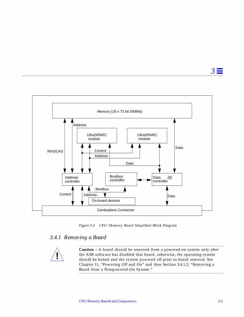
Figure 3-2 is a simplified block diagram of the CPU/Memory board. It includesan Address Controller (AC), 8 bit-sliced Data Controllers (DCs), a BootbusController (BC), on-board devices (including a Flash PROM, and SRAM), twoCPU processor slots, and slots for two memory banks of 8 SIMMs each.
!
CPU/Memory Boards and Components 3-5
3
Figure 3-2 CPU/Memory Board Simplified Block Diagram
3.4.1 Removing a Board
Caution – A board should be removed from a powered-on system only afterthe ASR software has disabled that board, otherwise, the operating systemshould be halted and the system powered off prior to board removal. SeeChapter 11, “Powering Off and On” and then Section 3.4.1.2, “Removing aBoard from a Nonpowered-On System.”
Centerplane Connector
Data (8)Addresscontroller
Memory (16 x 72 bit SIMMs)
Address Data
UltraSPARCmodule
UltraSPARCmodule
ControlAddress
Data
Data
Address
RAS/CAS
Control
controllerBootbuscontroller
Bootbus
On-board devices
!

3-6 Ultra Enterprise 3000 System Manual—May 1996
3
3.4.1.1 Removing a Board from a Powered-On System
1. Ensure that the board has been disabled by the ASR software. SeeSection 3.3, “Hot-Plug Feature.”Once disabled by ASR, one of two results occurs:
• The three LEDs on the board are not lit (board has no power).• The outer two green LEDs are not lit and the middle yellow LED is lit
(board in low power mode).
2. Use a Phillips #1 screwdriver to mechanically release the board from thesystem card cage.Insert the screwdriver into each quarter-turn access slot (the slots are locatedon the left and right sides of the board front panel) and then turn a quarterturn so that the arrow points to the unlocked position. See Figure 3-3.
Figure 3-3 Unlocking and Locking Quarter-Turn Access Slots
3. Pull the ends of both extraction levers outward simultaneously to unseatthe board centerplane connector from the centerplane receptacles.See Figure 3-4 for positioning of the extraction levers.
Unlocked Locked

CPU/Memory Boards and Components 3-7
3
Figure 3-4 CPU/Memory Board
4. If a board is not immediately replaced, a filler panel must be installed inits place.See Section 3.2, “Filler Panels.”
3.4.1.2 Removing a Board from a Nonpowered-On System
1. Use a Phillips #1 screwdriver to mechanically release the board from thesystem card cage.Insert the screwdriver into each quarter-turn access slot (the slots are locatedon the left and right sides of the board front panel) and then turn a quarterturn so that the arrow points to the unlocked position. See Figure 3-3 onpage 3-6.
2. Pull the ends of both extraction levers outward simultaneously to unseatthe board from the centerplane receptacles.See Figure 3-4 for positioning of the levers.
Extraction leverin extract/insertposition

3-8 Ultra Enterprise 3000 System Manual—May 1996
3
3. If a board is not immediately replaced, a filler panel must be installed inits place.See Section 3.2, “Filler Panels.”
3.4.2 Installing a Board
3.4.2.1 Board Slot Selection
Logically there is no difference between the board slots, and each slot canaccept any board type. However, since the lowest numbered board slot (slot 1)is the only slot connected to the onboard SCSI devices, this slot is usuallyreserved for the first I/O board. See Figure 3-5.
Note – Board slot numbers are marked on the chassis.
Figure 3-5 Board Slot Locations
Board slot5 3 1
s:
Clock board
7
System rear view
PCM

CPU/Memory Boards and Components 3-9
3
3.4.2.2 Cooling and Power Issues
To adhere to cooling and power requirements, there should be onepower/cooling module (PCM) for every two boards. The PCMs must beinstalled adjacent to populated board slots to ensure the fan in the PCM cancool the respective boards.
Note – All empty slots must have a filler panel installed to ensure propercooling. See Section 3.2, “Filler Panels.”
3.4.2.3 Powered-On or Nonpowered-On System
1. Carefully insert the board in the proper slot in the card cage, componentside to the right, ensuring that the board does not slip out of the top andbottom card guides.All empty slots must have a filler panel installed.
2. Ensure that both extraction levers are in the outward position as you slidethe board toward the centerplane receptacles.The board will not seat fully unless the levers are in this starting position.See Figure 3-4 on page 3-7 for positioning of the levers.
Caution – DO NOT FORCE any board into a slot; it can cause damage to theboard and system. The board should insert and seat smoothly. If it binds,remove the board and inspect the card cage slot for any obvious obstructions.Also inspect both the board and the centerplane for bent pins or other damage.
3. Use the extraction levers to seat the board.Simultaneously swing both levers inward to the locked position, mating theboard centerplane connector to the matching receptacle on the centerplane.Do not press on board front panel to seat it; doing so will damage theconnector pins.
4. Mechanically lock the board to the system chassis by inserting a Phillips#1 screwdriver into each quarter-turn access slot and then turning to thelocked position.See Figure 3-3 on page 3-6.
!

3-10 Ultra Enterprise 3000 System Manual—May 1996
3
5. Once the board is installed, when the system is powered on, a messagesimilar to the following will be displayed on the monitor:
Example depicts screen output when a new CPU/Memory board has beenhot-plugged into slot 5 of an operating Enterprise system:
Additionally, any subsequent prtdiag(1M) output would includeinformation for board slot 5. Again, note that the system will not use thenew board until the system is rebooted.
6. Reboot the system now or schedule a later time to reboot when systemdisruption will be minimized.
3.4.3 UltraSPARC Modules
Each CPU/Memory board has four connectors for UltraSPARC modules (up totwo modules per board, two connectors per module). For each module, there isa connector with 144 pins and a connector with 288 pins. See Figure 3-6.
3.4.4 Handling Precautions
The following precautions should be exercised when handling UltraSPARCmodules:
• UltraSPARC modules are static-sensitive and a grounding wrist strap fieldkit must be used when handling the modules.
• Always handle the modules by the edges and not by the smaller black heatsinks that break easily if handled improperly.
• Do not handle the modules by touching the gold pins on the compressionconnectors. Natural oils on the hands cause these connectors to oxidize andcorrode over a period of time, resulting in the need for module cleaning orreplacement.
NOTICE: CPU Board Hotplugged into Slot 5NOTICE: Board 5 is ready to remove

CPU/Memory Boards and Components 3-11
3
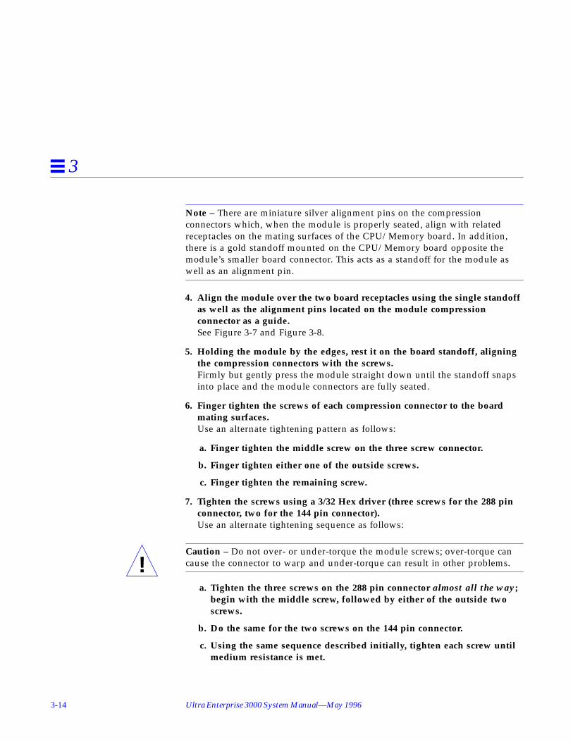
Figure 3-6 UltraSPARC Module Connector Detail
3.4.4.1 Removing a Module
Each module is locked to the main board with a single standoff and isconnected to the main board by two connectors. The pins within the connectorsare compressed to the corresponding board pin receptacles by a metalcompression bar which, when secured with screws, compresses the moduleconnector pins to the board receptacle pins. See Figure 3-7.
288 pin connector
144 pin connector
Screws(2 places)
Screws(3 places)

3-12 Ultra Enterprise 3000 System Manual—May 1996
3
Figure 3-7 UltraSPARC Module Connector Detail
1. Use the procedures in Section 3.4.1, “Removing a Board,” to remove theapplicable CPU/Memory board.
Warning – The heatsinks on the UltraSPARC modules may be hot. Use cautionwhen removing or installing UltraSPARC modules and avoid contact.
2. Use a 3/32 Hex driver to loosen all screws from each of the compressionbars. Two screws for the 144 pin connector, three screws for the 288 pinconnector.See Figure 3-6.
3. Lift the module straight up off the board mating surface and the singlestandoff that locks the module to the board.See Figure 3-8.
Compression bar

CPU/Memory Boards and Components 3-13
3
Figure 3-8 UltraSPARC Module Removal and Replacement
4. Place the module in an antistatic bag.
3.4.4.2 Installing a Module
To maximize performance when installing UltraSPARC modules on aCPU/Memory board, use all CPU 0 connectors on the lowest numbered slot tothe highest numbered slot. After this, if there are modules remaining, use theCPU 1 connectors in the same order.
1. Take the UltraSPARC module out of the protective packaging and inspectfor dust on the connectors.
2. Remove the applicable CPU/Memory board as indicated in Section 3.4.1,“Removing a Board.”
3. Inspect the board module mating surface. If the surface requires cleaning,use a cotton swab to clean debris from the mating surfaces.
Standoff,1 per module
3-14 Ultra Enterprise 3000 System Manual—May 1996
3
Note – There are miniature silver alignment pins on the compressionconnectors which, when the module is properly seated, align with relatedreceptacles on the mating surfaces of the CPU/Memory board. In addition,there is a gold standoff mounted on the CPU/Memory board opposite themodule’s smaller board connector. This acts as a standoff for the module aswell as an alignment pin.
4. Align the module over the two board receptacles using the single standoffas well as the alignment pins located on the module compressionconnector as a guide.See Figure 3-7 and Figure 3-8.
5. Holding the module by the edges, rest it on the board standoff, aligningthe compression connectors with the screws.Firmly but gently press the module straight down until the standoff snapsinto place and the module connectors are fully seated.
6. Finger tighten the screws of each compression connector to the boardmating surfaces.Use an alternate tightening pattern as follows:
a. Finger tighten the middle screw on the three screw connector.
b. Finger tighten either one of the outside screws.
c. Finger tighten the remaining screw.
7. Tighten the screws using a 3/32 Hex driver (three screws for the 288 pinconnector, two for the 144 pin connector).Use an alternate tightening sequence as follows:
Caution – Do not over- or under-torque the module screws; over-torque cancause the connector to warp and under-torque can result in other problems.
a. Tighten the three screws on the 288 pin connector almost all the way;begin with the middle screw, followed by either of the outside twoscrews.
b. Do the same for the two screws on the 144 pin connector.
c. Using the same sequence described initially, tighten each screw untilmedium resistance is met.
!

CPU/Memory Boards and Components 3-15
3
d. Using the same sequence, tighten each screw an additional 3/4 turn.
Figure 3-9 Tightening Compression Bar Screws
8. Use the procedures in Section 3.4.2, “Installing a Board,” to replace theapplicable CPU/Memory board.
3.4.5 Memory Modules (SIMMs)
The CPU/Memory board has 16 SIMM sockets, which are divided into twobanks of 8 SIMMs each, Bank 0 and Bank 1. Bank 0 and Bank 1 SIMMs occupyalternate slot locations; Bank 0 SIMMs are in the even numbered slots, andBank 1 SIMMs are in odd numbered slots. See Figure 3-10.
3-16 Ultra Enterprise 3000 System Manual—May 1996
3
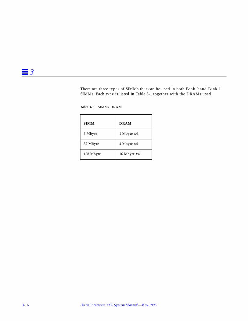
There are three types of SIMMs that can be used in both Bank 0 and Bank 1SIMMs. Each type is listed in Table 3-1 together with the DRAMs used.
Table 3-1 SIMM/DRAM
SIMM DRAM
8 Mbyte 1 Mbyte x4
32 Mbyte 4 Mbyte x4
128 Mbyte 16 Mbyte x4

CPU/Memory Boards and Components 3-17
3
Figure 3-10 Layout of CPU/Memory Board
DCDCDCDCDCDCDCDC AC
B0-J3100
B0-J3200
B0-J3400
B0-J3500
B0-J3300
B0-J3600
B0-J3800
B0-J3700
B1-J3101
B1-J3501
B1-J3301
B1-J3401
B1-J3601
B1-J3701
B1-J3801
B1-J3201
SRAM
FHC35W DC2DC 35W DC2DC
144 connector
144 connector
288
conn
ecto
r28
8 co
nnec
tor
720 centerplane connector
Bank 0 Bank 1
CPU1
CPU0
SRAM
3-18 Ultra Enterprise 3000 System Manual—May 1996
3
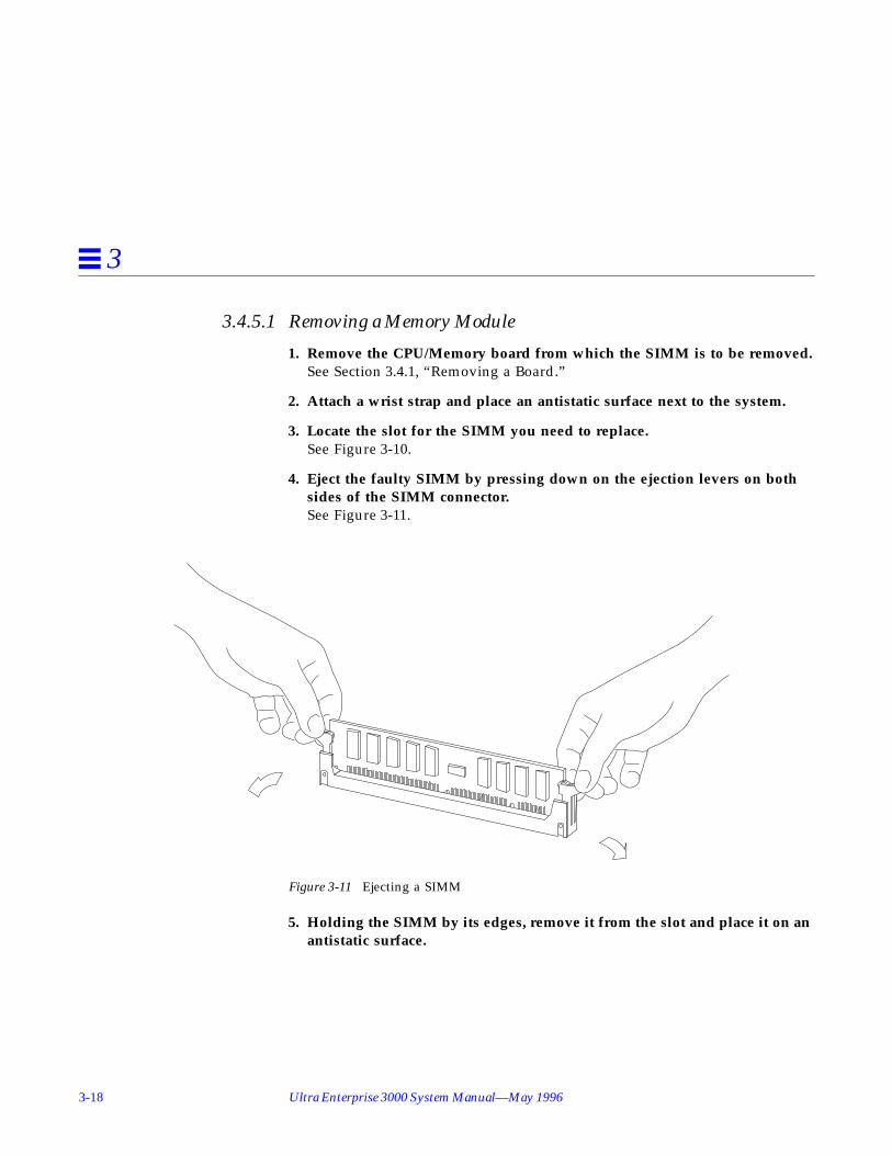
3.4.5.1 Removing a Memory Module
1. Remove the CPU/Memory board from which the SIMM is to be removed.See Section 3.4.1, “Removing a Board.”
2. Attach a wrist strap and place an antistatic surface next to the system.
3. Locate the slot for the SIMM you need to replace.See Figure 3-10.
4. Eject the faulty SIMM by pressing down on the ejection levers on bothsides of the SIMM connector.See Figure 3-11.
Figure 3-11 Ejecting a SIMM
5. Holding the SIMM by its edges, remove it from the slot and place it on anantistatic surface.

CPU/Memory Boards and Components 3-19
3
3.4.5.2 Installing a Memory Module
RequirementsAll banks must have the same size SIMMs. However, SIMMs from differentmanufactures are interchangeable in a single bank if the SIMMs all have thesame capacity and speed. Sort the SIMMs into banks of eight using the samesize SIMMs.
Maximizing PerformanceThe following guidelines will result in optimal memory interleaving acrossboards for performance. These guidelines are for optimal performance and arenot requirements for a functional system. The guidelines apply to systems withno SIMMS installed and when adding SIMMs to a system. If you are addingSIMMs, you may need to move some SIMMs to meet the guidelines.
1. Install one bank on each board before installing the second bank on anyboard.It does not matter whether the first bank is bank 0 or bank 1.
2. Begin with the largest density banks first (128 Mbyte SIMMs), continuewith medium sized banks (32 Mbyte SIMMs), and finish with the smallestbanks (8 Mbyte SIMMs).
3. If there is remaining memory, start filling the second banks on the boardsin the same order as the first banks.
Installation1. Place the CPU/Memory board on which the SIMM is to be installed on an
antistatic mat.
2. Carefully remove the new SIMM from its protective packaging and placeit on an antistatic surface.The bag that the SIMM is packed in makes a good antistatic surface.
3. Press down on the ejector levers at both ends of the SIMM connector slotthat will receive the new SIMM.The connector slot will not accept the SIMM unless the levers are in theinsert position. See Figure 3-12.

3-20 Ultra Enterprise 3000 System Manual—May 1996
3
4. Align the SIMM with the slot.Hold the SIMM by its edges and orient it so that the two notches at thebottom of the SIMM line up with the two tabs in the SIMM connector. SeeFigure 3-12.
5. Place your thumbs on the top edge of the SIMM and push the SIMMfirmly into its connector.
6. Lock the SIMM in place by pushing both ejector levers into the uprightposition.
7. Install the CPU/Memory board and detach the wrist strap.See Section 3.4.2, “Installing a Board.”
8. As you reboot the system, watch for the system banner to verify that thenew memory is recognized by the system.
Figure 3-12 Orienting and Installing a SIMM
Notch alignment

4-1
I/O Boards and Components 4
To protect both yourself and the equipment, make sure you follow precautionsin Chapter 2, “Safety Precautions and Tools Requirements.”
For your protection, also observe the following safety precautions when settingup your equipment:
• Follow all cautions, warnings, and instructions marked on the equipment.• Never push objects of any kind through openings in the equipment as they
may touch dangerous voltage points or short out components that couldresult in fire or electric shock.
• Refer servicing of equipment to qualified personnel.
Handling Boards and Assemblies page 4-2
Safety Precautions page 2-1
Hot-Plug Feature page 4-4
I/O Boards page 4-4
SBus Cards page 4-15
Graphics (UPA) Cards page 4-23
Fibre Cards page 4-27
Connectors page G-5

4-2 Ultra Enterprise 3000 System Manual—May 1996
4
4.1 Handling Boards and Assemblies
Caution – The chassis AC power cord must remain connected to ensure aproper ground.
Caution – The I/O boards, their modules, and cards have surface-mountcomponents that can be broken by flexing the boards.
To minimize the amount of board flexing, observe the following precautions:
• Hold the board only by the edges near the middle of the board, where theboard stiffener is located. Do not hold the board only at the ends.
• When removing the board from an antistatic bag, keep the board verticaluntil you lay it on the Sun ESD mat.
• Do not place the board on a hard surface. Use a cushioned antistatic mat.The board connectors and components have very thin pins that bend easily.
• Do not use an oscilloscope probe on the components. The soldered pins areeasily damaged or shorted by the probe point.
• Transport the board in an antistatic bag.• Be careful of small parts located on the component side of the board.
4.2 Filler PanelsAll empty board slots in Enterprise 3000 systems must have a filler panelinstalled for cooling purposes. Filler panels are inserted into a board slot withthe springfingers facing to the right. See Figure 4-1.
!
!

I/O Boards and Components 4-3
4
Figure 4-1 Filler Panel
4.3 SCSI TerminationThe I/O board in slot 1 controls the internal SCSI tray devices. Therefore, theexternal SCSI connector on the I/O board in slot 1 of a system must beterminated with a SCSI terminator. See Figure 4-2.
Figure 4-2 SCSI Terminator
Springfingers

4-4 Ultra Enterprise 3000 System Manual—May 1996
4
4.4 Hot-Plug FeatureEnterprise 3000 systems have extensive error detection mechanisms, and anAutomatic System Reconfiguration (ASR) feature that enables the system to berebooted with failed components (such as CPUs, memory, or I/O) disabled.When an error is detected, the system can be reconfigured so that the boardcontaining the failed components is placed in low power mode and is nolonger accessible.
Caution – If the message: NOTICE: Hot Plug not supported in thissystem is displayed during boot, do NOT attempt hot-plug in this system ordamage to the hardware will occur.
The hot-plug feature is the ability to insert a new board into a powered-onsystem, despite being “live,” or being supplied with electrical power. Once aworking board is added to a powered-on system with the hot-plug feature, thesystem will not use the new board until the system is rebooted.
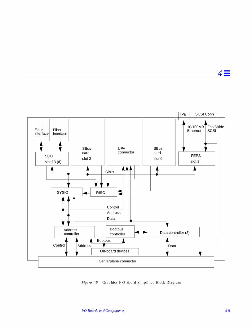
4.5 I/O BoardsEnterprise 3000 systems support two types of I/O boards: SBus and Graphics.See Figure 4-3 through Figure 4-6.
Note – SBus connector slots 1 and 2 on the SBus I/O board can accommodate adouble-wide SBus card.
The SBus I/O board includes two SYSIO ASICs that provide two SBuses:
• One for two plug-in SBus cards and two fiber interfaces• One for one plug-in SBus card and the on-board devices (10/100Mbyte TPE
and Fast/Wide SCSI)
The Graphics I/O board includes one SYSIO ASIC that provides a single SBusfor two plug-in SBus cards, as well as the same on-board devices described forthe SBus I/O board (10/100Mbyte TPE and Fast/Wide SCSI). See Figure 4-5and Figure 4-6 for simplified block diagrams of each board.
!
I/O Boards and Components 4-5
4
4.5.1 tpe-link-test? Variable
If the system cannot communicate with a network, the tpe-link-test?settings for the on-board Ethernet ports may be incompatible with the settingat the network hub. The tpe-link-test? variable is set separately for the on-board Ethernet port on each I/O board. The variable is also set for any SBusEthernet cards in the system.If you have problems verifying connection between Sun equipment and yourhub, verify that your hub also has the link test function enabled.See Section 8.5.3.2, “printenv Command,” for information about displayingconfiguration variables and Section 8.6.1, “Failure of NetworkCommunications,” for additional tpe-link-test? information. Also, refer tothe manual provided with your hub.

4-6 Ultra Enterprise 3000 System Manual—May 1996
4
Figure 4-3 SBus I/O Board Components Locations
DCDCDCDCDCDCDCDC
FHC SYSIO SYSIO RISC
RISCSOC
PHY
Fiber 0 Fiber 1
SBus connector 2 SBus connector 1 SBus connector 0
AC
720 Centerplane connector
SCSI connector TPE MII connector
J2500
FEPS

I/O Boards and Components 4-7
4
Figure 4-4 Graphics I/O Board Components Locations
DCDCDCDCDCDCDCDC
FHC SYSIO RISC
SOC
PHY
FEPS
Fiber 0 Fiber 1
SBus connector 2 Graphics (UPA) connector SBus connector 0
AC
720 Centerplane connector
SCSI connector TPE MII connector
J2500

4-8 Ultra Enterprise 3000 System Manual—May 1996
4
Figure 4-5 SBus I/O Board Simplified Block Diagram
Fiberinterface
SYSIO B
SCSI Conn
SBus
Data controller (8)Addresscontroller
Address DataControl
Control
Address
Data
TPE
SBuscard
SBuscard
SBuscard
FEPSSOC
Fiber
RISC
Centerplane connector
interface
SYSIO A RISC
Bootbuscontroller
Bootbus
On-board devices
slot 0slot 2slot 13 (d) slot 3
Fast/WideSCSI
10/100MBEthernet
slot 1
I/O Boards and Components 4-9
4
Figure 4-6 Graphics I/O Board Simplified Block Diagram
Fiberinterface
SCSI Conn
SBus
Data controller (8)Addresscontroller
Address DataControl
Control
Address
Data
TPE
SBuscard
SBuscard
UPA
FEPSSOC
Fiber
Centerplane connector
interface
SYSIO RISC
Bootbuscontroller
Bootbus
On-board devices
slot 0slot 2slot 13 (d) slot 3
Fast/WideSCSI
10/100MBEthernet
connector

4-10 Ultra Enterprise 3000 System Manual—May 1996
4
4.5.2 Removing a Board
4.5.2.1 Removing a Board from a Powered-On System
Caution – A board should be removed from a powered-on system only afterthe ASR software has disabled that board, otherwise, the operating systemshould be halted and the system powered off prior to board removal. SeeChapter 11, “Powering Off and On” and then Section 4.5.2.2, “Removing aBoard from a Nonpowered-On System.”
1. Ensure that the board has been disabled by the ASR software. SeeSection 4.4, “Hot-Plug Feature.”Once disabled by ASR, one of two results occurs:
• The three LEDs on the board are not lit (board has no power).• The outer two green LEDs are not lit and the middle yellow LED is lit
(board in low power mode).
2. Unfasten any cable connectors from the front panel and set them aside.Label cables to identify them for reconnection later.
3. Mechanically release the board from the system cabinet by inserting aPhillips #1 screwdriver into each quarter-turn access slot and then turningto the unlocked position.See Figure 4-7.
Figure 4-7 Unlocking and Locking Quarter-Turn Access Slots
!
Unlocked Locked

I/O Boards and Components 4-11
4
4. Pull the ends of both extraction levers outward simultaneously to unseatthe board centerplane connector from the centerplane receptacles.See Figure 4-8.
Figure 4-8 I/O Board (Graphics)
5. If a board is not immediately replaced, a filler panel must be installed inits place.See Section 4.2, “Filler Panels.”
4.5.2.2 Removing a Board from a Nonpowered-On System
1. Mechanically release the board from the system chassis by inserting aPhillips # 1 screwdriver into each quarter-turn access slot and thenturning to the unlocked position.See Figure 4-7 on page 4-10.
Extraction leverin extract/insertposition

4-12 Ultra Enterprise 3000 System Manual—May 1996
4
2. Unfasten any cable connectors from the front panel and set them aside.Label cables to identify them for reconnection later.
3. Pull the ends of both extraction levers outward simultaneously to unseatthe board from the centerplane receptacles.See Figure 4-8 on page 4-11.
4. If a board is not immediately replaced, a filler panel must be installed inits place.See Section 4.2, “Filler Panels.”
Figure 4-9 Board Removal and Replacement
Board slot5 3 1
s:
Clock board
7
PCM
System rear view

I/O Boards and Components 4-13
4
4.5.3 Installing a Board
4.5.3.1 Board Slot Selection
Logically there is no difference between the board slots, and each slot canaccept any board type. However, since the lowest numbered board slot (slot 1)is the only slot connected to the onboard SCSI devices, this slot is usuallyreserved for the first I/O board. Board slot numbers are marked on the chassis.See Figure 4-9.
4.5.3.2 Cooling and Power Issues
To adhere to cooling and power requirements, there should be onepower/cooling module (PCM) for every two boards. The PCMs must beinstalled adjacent to populated board slots to ensure the fan in the PCM cancool the respective boards.
Note – All empty slots must have a filler panel installed to ensure propercooling.
4.5.3.3 Powered-On or Nonpowered-On System
1. Carefully insert the board (component side to the right) in the proper slotin the card cage, ensuring that the board does not slip out of the top andbottom card guides.All empty slots must have a filler panel installed.
2. Ensure that both extraction levers are in the outward position as you slidethe board toward the centerplane receptacles.The board will not seat fully unless the levers are in this starting position.See Figure 4-8 on page 4-11 for lever positioning.
3. Slowly insert the board until the board centerplane connector is justtouching the centerplane receptacle.

4-14 Ultra Enterprise 3000 System Manual—May 1996
4
Caution – DO NOT FORCE any board into a slot; this can cause damage to theboard and system. The board should insert and seat smoothly. If it binds,remove the board and inspect the card cage slot for any obvious obstructions.Also inspect both the board and the centerplane for bent pins or other damage.
4. Use the extraction levers to seat the board.Simultaneously swing both levers inward to the locked position, mating theboard centerplane connector to the matching receptacle on the centerplane.Do not press on board front panel to seat it; doing so will damage theconnector pins.
5. Mechanically lock the board to the system chassis by inserting a Phillips#1 screwdriver into each quarter-turn access slot and then turning to thelocked position.See Figure 4-7 on page 4-10.
6. Replace or connect all necessary cables to the front of the board.
Note – The I/O board in slot 1 controls the internal SCSI tray devices.Therefore, the external SCSI connector on the I/O board in slot 1 of a systemmust be terminated with a SCSI terminator. See Figure 4-2 on page 4-3.
7. Terminate the board SCSI out connector if required. See “Note” above.
8. Once the board is installed, when the system is powered on, a messagesimilar to the following will be displayed on the monitor:
Example depicts screen output when a new I/O board has been hot-pluggedinto slot 3 of an operating Enterprise 3000 system:
Additionally, any subsequent prtdiag(1M) output would includeinformation for board slot 3. Again, note that the system will not use thenew board until the system is rebooted.
9. Reboot the system now or schedule a later time to reboot when systemdisruption will be minimized.
NOTICE: I/O Board Hotplugged into Slot 3NOTICE: Board 3 is ready to remove
!

I/O Boards and Components 4-15
4
4.5.4 SBus Cards
There are three SBus card locations on the SBus I/O board; the Graphics I/Oboard has two. Figure 4-10 shows the SBus card locations for both types ofboards.

4-16 Ultra Enterprise 3000 System Manual—May 1996
4
Figure 4-10 I/O Board SBus Card Locations
SBus 0
SBus 1
SBus 2
SBus I/O board
Graphics I/O board
SBus 0
SBus 2
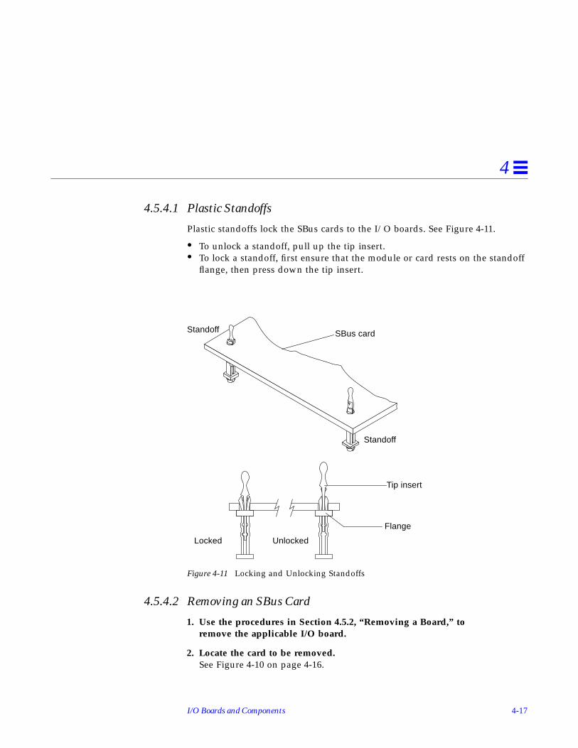
I/O Boards and Components 4-17
4
4.5.4.1 Plastic Standoffs
Plastic standoffs lock the SBus cards to the I/O boards. See Figure 4-11.
• To unlock a standoff, pull up the tip insert.• To lock a standoff, first ensure that the module or card rests on the standoff
flange, then press down the tip insert.
Figure 4-11 Locking and Unlocking Standoffs
4.5.4.2 Removing an SBus Card
1. Use the procedures in Section 4.5.2, “Removing a Board,” toremove the applicable I/O board.
2. Locate the card to be removed.See Figure 4-10 on page 4-16.
UnlockedLocked
Standoff SBus card
Tip insert
Flange
Standoff

4-18 Ultra Enterprise 3000 System Manual—May 1996
4
3. Remove the two screws that secure the SBus card to the I/O board frontpanel.Save the screws for installation of a replacement SBus card or a filler panel.
4. Unlock the SBus card by pulling up the tips of the two standoffs.See Figure 4-11 on page 4-17.
5. Hold the card by the edges near the connector and gently rock the cardback and forth to loosen it from the socket.You may have to remove the SBus cards or the graphics (UPA) card next tothis card in order to have enough room to hold onto the SBus card beingremoved.
Caution – The connector housing may break if the SBus card is tilted too far.
6. Lift the SBus card from the socket at an angle while guiding the face plateout from the back panel opening.See Figure 4-12.
Figure 4-12 Removing or Installing an SBus Card
!

I/O Boards and Components 4-19
4
7. Place the SBus card in an antistatic bag.
8. If the SBus card is not immediately replaced, install a filler panel (partnumber 340-2305) on the I/O board back panel opening. To secure thefiller panel, use the screws that were removed in Step 3.
Caution – Be sure to install the filler panel right-side up. Installing it upsidedown creates a gap at the top edge of the SBus slot opening that can impairsystem cooling and regulatory compliance.
9. Replace the I/O board. Use the procedures in Section 4.5.3, “Installing aBoard.”
4.5.4.3 Installing an SBus Card
Note – If the new SBus card does not have an adapter plate or the LinkIntegrity Test feature, proceed to “Installing an SBus Card” on page 4-22.
Preparing to Install1. Attach a wrist strap and take the SBus card out of the protective
packaging. Place the SBus card on an antistatic mat.
2. Remove the adapter bracket from the SBus card rear panel.See Figure 4-13. Remove the two screws securing the adapter to the cardrear panel (the adapter bracket and the screws are not needed for thisinstallation).
!

4-20 Ultra Enterprise 3000 System Manual—May 1996
4
Figure 4-13 SBus Card Rear Panel with Adapter
3. Remove the black plastic card retainer shipped with the card.See Figure 4-14. Spread the ends of the retainer apart to remove it from thecard (the retainer is not needed for this installation).
Figure 4-14 Card Retainer
Link Integrity Test1. Ensure that the SBus card is on an antistatic mat.
2. For DSBE/S and FSBE/S cards: remove the two outer retaining screws (seeFigure 4-15), but do NOT remove the middle screw or the springfinger.Use a Phillips #0 screwdriver and a 3/16 nut driver or socket wrench.
Remove adapter
Remove screws
Card retainer

I/O Boards and Components 4-21
4
3. For DSBE/S and FSBE/S cards, configure jumper J0302 for link integritytest functionality.See Figure 4-15 (DSBE/S) or Figure 4-16 (FSBE/S).
a. Put the shunt over both pins to disable the Link Integrity Test. SeeFigure 4-17 “Disabled.”
b. Put the shunt in one pin to enable the Link Integrity Test. SeeFigure 4-17 “Enabled.”
Caution – If you choose to disable the test, it must be disabled both at the huband at the SBus card. In the event of “loss of carrier” or “not responding”problems, check the status of the link enable on both the SBus card and thehub.
Figure 4-15 DSBE/S SBus Card
!
Back panel
Springfinger
JackscrewsPhillips screw
Jumper J0302

4-22 Ultra Enterprise 3000 System Manual—May 1996
4
Figure 4-16 FSBE/S SBus Card
Figure 4-17 Disabling and Enabling the Link Integrity Test
Installing an SBus Card1. Use the procedures in Section 4.5.2, “Removing a Board,” to
remove the applicable SBus I/O or Graphics I/O board.
2. Locate the SBus connector that the card is to be installed in.See Figure 4-10 on page 4-16.
3. If a filler panel covers the front panel SBus slot, remove the two screwsand detach the filler panel.Retain the screws to attach the SBus card to the back panel, unless the cardhas a wide connector, or set of connectors.
4. Unlock the tip inserts of the two standoffs for the SBus slot.See Figure 4-11 on page 4-17.
J0302
Disabled Enabled2 1 2 1

I/O Boards and Components 4-23
4
5. Attach a wrist strap and take the SBus card out of the protectivepackaging. Inspect the pins in the connector to make sure they are notbent.
6. Guide the SBus card face plate under the springfinger and against the rearface of the I/O board front panel.The I/O connectors of the SBus card should be visible through the openingin the I/O board front panel.
7. Hold the card by the edges nearest the SBus connector and place the cardover the two standoffs.
8. Hold the SBus card by the edges near the connector and firmly but gentlypress the card down until the connector is fully seated.To align the connector and socket, push the card toward the I/O board frontpanel.
Caution – Do not rock the card onto the socket; the plastic connector housingmay break.
9. Press each corner of the SBus card to ensure that it rests on the collar ofthe standoff.
10. Press down on the tip insert of each standoff to lock the card in place.
11. Replace and tighten the back panel screws to secure the SBus card to theI/O board front panel.
12. Replace the I/O board using the procedures described in Section 4.5.3,“Installing a Board.”
4.5.5 Graphics (UPA) Cards
The Graphics I/O board contains a single connector that accommodatesgraphics (UPA) cards. See Figure 4-18.
!

4-24 Ultra Enterprise 3000 System Manual—May 1996
4
Figure 4-18 Graphics (UPA) Card Connector Location
4.5.5.1 Removing a Graphics (UPA) Card
1. Use the procedures in Section 4.5.2, “Removing a Board,” to remove theapplicable Graphics I/O board.
2. Locate the card.See Figure 4-19.
3. Remove the two screws that secure the card to the I/O board front panel.Save the screws for installation of a replacement card or a filler panel.
4. Unlock the card by pulling up the tips of the two standoffs.See Figure 4-11 on page 4-17.
5. Hold the card by the edges near the connector and gently rock the cardback and forth to loosen it from the socket.You may have to remove the SBus cards next to this card in order to haveenough room to hold onto the graphics (UPA) card being removed.
UPA connector

I/O Boards and Components 4-25
4
Caution – The connector housing may break if the card is tilted too far.
6. Lift the card from the socket at an angle while guiding the face plate outfrom the front panel opening.See Figure 4-19.
Figure 4-19 Removing or Installing a Graphics (UPA) Card
7. Place the card in an antistatic bag.
!

4-26 Ultra Enterprise 3000 System Manual—May 1996
4
8. If the graphics (UPA) card is not immediately replaced, install a fillerpanel (part number 340-2305) on the Graphics I/O board front panelopening.To secure the filler panel, use the screws that were removed in Step 3.
Caution – Be sure to install the filler panel right-side up. Installing it upsidedown creates a gap at the top edge of the card slot opening that can impairsystem cooling and FCC regulatory compliance.
9. Use the procedures in Section 4.5.3, “Installing a Board,” to replace theGraphics I/O board.
4.5.5.2 Installing a Graphics (UPA) Card
1. Use the procedures described in Section 4.5.2, “Removing a Board,” toremove the applicable Graphics I/O board.
2. Attach a wrist strap and take the graphics (UPA) card out of the protectivepackaging and place the card on an antistatic mat.Inspect the pins in the connector to make sure they are not bent.
3. Remove the adapter bracket from the rear panel of the card.See Figure 4-13 on page 4-20. Remove the two screws securing the adapterto the card rear panel (the adapter bracket and the screws are not needed forthis installation).
4. Remove the black plastic card retainer shipped with the card.See Figure 4-14 on page 4-20. Spread the ends of the retainer apart toremove it from the card (the retainer is not needed for this installation).
5. Locate the graphics (UPA) connector for the card.See Figure 4-18 on page 4-24.
6. If a filler panel covers the I/O board front panel slot for the graphics(UPA) card, remove the two screws and detach the filler panel.Retain the screws to attach the graphics (UPA) card to the front panel, unlessthe card has a wide connector, or set of connectors.
7. Unlock the tip inserts for the two standoffs for the graphics (UPA)connector slot.See Figure 4-11 on page 4-17.
!

I/O Boards and Components 4-27
4
8. Hold the card at an angle as depicted in Figure 4-19 on page 4-25. Guidethe card face plate under the springfingers and against the rear face of theI/O board front panel.The I/O connectors of the card should be visible through the opening in theI/O board front panel once the card is properly positioned.
9. Hold the card by the edges nearest the graphics (UPA) connector andplace the card over the two standoffs.
10. Hold the card by the edges near the connector and firmly but gently pressthe card down until the connector is fully seated.To align the connector and socket, push the card toward the Graphics I/Oboard front panel.
Caution – Do not rock the card onto the socket; the plastic connector housingmay break.
11. Press each corner of the card to ensure that it rests on the collar of thestandoff.
12. Press down on the tip insert of each standoff to lock the card in place.
13. Replace and tighten the front panel screws to secure the card to theGraphics I/O board front panel.See Figure 4-12 on page 4-18
14. Use the procedures in Section 4.5.3, “Installing a Board,” to replace theGraphics I/O board.
4.5.6 Fibre Cards
4.5.6.1 Removing a Fibre Card
1. Use the procedures in Section 4.5.2, “Removing a Board,” to remove theapplicable I/O board.
2. Locate the card to be removed. See Figure 4-20.You may have to remove the SBus cards over or next to this card in order tohave enough room to hold onto the fibre card being removed. SeeFigure 4-21.
!

4-28 Ultra Enterprise 3000 System Manual—May 1996
4
Figure 4-20 I/O Board Fibre Card Connector Locations
Graphics I/O board
SBus I/O board
Fiber 1
Fiber 0
Fiber 1
Fiber 0

I/O Boards and Components 4-29
4
Note – There are four plastic standoffs located on the bottom of each card, twoon each end. These secure the card once they are inserted into correspondingopenings on the I/O board. See detail in Figure 4-21.
Figure 4-21 Removing or Installing A Fibre Card
Card standoffs(4 per card)
Standoff openings onI/O board (4 per fibrecard)

4-30 Ultra Enterprise 3000 System Manual—May 1996
4
3. Unseat the card from the I/O board:
a. Grasp the card underneath each corner on the end of the card thatconnects to the I/O board receptacle (opposite the I/O board frontpanel end), then firmly unseat the two standoffs as well as the cardconnector.
b. Grasp the card underneath each corner near the I/O board front panel,and then firmly unseat the remaining two standoffs from the I/Oboard.
4. Once the card standoffs and connector are unseated, hold the card at aslight angle as depicted in Figure 4-21 on page 4-29. Guide the card fiberconnector end from the front panel opening on the I/O board.
5. If the fibre card is not immediately replaced, install an OLC plug on theI/O board front panel opening.
6. Use the procedures in Section 4.5.3, “Installing a Board,” to replace theI/O board.
4.5.6.2 Installing a Fibre Card
1. Use the procedures in Section 4.5.2, “Removing a Board,” to remove theapplicable I/O board.
Note – If required, remove the OLC plug that protects the fiber optic connectoropening on the front panel of the I/O board. These OLC plugs are installed infactory shipped systems without fibre cards installed.
2. Locate the card slot for installation.See Figure 4-20 on page 4-28. You may need to remove the SBus cards over(or next to) this card to have enough room to hold onto the fibre card beinginstalled.
Note – There are four plastic standoffs located on the bottom of each card, twoon each end of the card. These secure the card once they are inserted intocorresponding openings on the I/O board. See detail in Figure 4-21 onpage 4-29.
I/O Boards and Components 4-31
4
3. Hold the card at a slight angle and position it so the fiber connector end isloosely inserted into the I/O board front panel opening.
4. Align the card over the I/O board fiber connector receptacle and over thefour standoff holes on the I/O board.See Figure 4-21 on page 4-29.
5. Seat the card:
a. Grasp the card underneath each corner near where the card connects tothe I/O board fiber connector receptacle. Firmly seat the card on theconnector and on the two adjacent standoffs.
b. On the end of the card near the I/O board front panel, grasp the cardunderneath each side and firmly seat the remaining two standoffs.
6. Use the procedures in Section 4.5.3, “Installing a Board,” to replace theI/O board.

4-32 Ultra Enterprise 3000 System Manual—May 1996
4

5-1
Clock Board 5
To protect both yourself and the equipment, make sure you follow precautionsin Chapter 2, “Safety Precautions and Tools Requirements.”
For your protection, also observe the following safety precautions when settingup your equipment:
• Follow all cautions, warnings, and instructions marked on the equipment.• Never push objects of any kind through openings in the equipment as they
may touch dangerous voltage points or short out components that couldresult in fire or electric shock.
• Refer servicing of equipment to qualified personnel.
Safety Precautions page 2-1
Clock Board page 5-2
Connectors page G-11
5-2 Ultra Enterprise 3000 System Manual—May 1996
5
5.1 Handling Boards and Assemblies
Caution – The chassis AC power cord must remain connected to ensure aproper ground.
Caution – The clock board and its modules have surface-mount componentsthat can be broken by flexing the board.
To minimize the amount of board flexing, observe the following precautions:
• Hold the board only by the edges near the middle of the board, where theboard stiffener is located. Do not hold the board only at the ends.
• When removing the board from an antistatic bag, keep the board verticaluntil you lay it on the Sun ESD mat.
• Do not place the board on a hard surface. Use a cushioned antistatic mat.The board connectors and components have very thin pins that bend easily.
• Do not use an oscilloscope probe on the components. The soldered pins areeasily damaged or shorted by the probe point.
• Transport the board in an antistatic bag.
5.2 Clock BoardThere is one clock board for each Enterprise 3000 system. See Figure 5-1. Theclock board provides:
• Programmable system and processor clock• Serial, keyboard, and mouse ports for the console• Centralized Time-of-day (TOD) chip that includes NVRAM• Centralized reset logic• Status and control of power supplies
The clock board consists of the following subsystems:
• ConsoleBus• Clocks• Reset logic• JTAG• Centerplane connector signals
!
!

Clock Board 5-3
5
Figure 5-1 Clock Board
Figure 5-2 depicts a block diagram of the subsystems and centerplaneconnector.
Extraction lever
Captive screw (2)
(retract/insert position)

5-4 Ultra Enterprise 3000 System Manual—May 1996
5
Figure 5-2 Clock Board Simplified Block Diagram
Centerplane
Reset
Console
Clocks
+5VDC+3.3VDC
JTAG JTAGBus
Keyboard/
Resetbutton
Clock_Frequency
ConsoleBus
ClockBus
ResetBuscb_man_reset
cb_sys_reset
Serial ports
mouse
LEDs led[2..0]
connector
Resetbutton(xir)

Clock Board 5-5
5
5.2.1 ConsoleBus
The ConsoleBus provides system boards access to global system control andstatus as well as to the keyboard, mouse, and serial ports. In addition, there isa NVRAM/TOD chip that maintains the date and time and 8 Kbytes of datawhen the power to the system is shut off.
The state of physical hardware conditions is maintained in registers on theclock board. Each of these registers has inputs generated from othersubsystems on the clock board, from other boards, or from the power suppliesin the system. Some clock board registers are reserved for controlling variousstates of the machine.
The ConsoleBus also provides a serial port interface and a keyboard/mouseinterface. The primary purpose of the serial port interface is to provide POSTmessages during power on. The serial port can be used as a console forsystems without a keyboard and display, and for standard serial peripheralhook-ups such as modems and printers.
5.2.2 Clocks
The clock subsystem generates the clocks for the entire system. The base clockis synthesized and then divided into various frequencies. The base clocks arethen “fanned-out” and driven to the centerplane by an array of driver chips.Two processor clocks and one system clock go to each of the board slots on thecenterplane.
5.2.3 Reset logic
The reset logic consists of four subcircuits for controlling the system reset anderror state:
• Manual reset• System reset• XIR• System error

5-6 Ultra Enterprise 3000 System Manual—May 1996
5
5.2.4 Removing a Clock Board
The clock board slot is located in the system rear, to the right of the board slots.See Figure 5-3.
Caution – The clock board is not hot-pluggable. Do not remove the clockboard until the system has been halted and powered off.
You must halt the operating system before turning off the system power. SeeChapter 11, “Powering Off and On” for this procedure.
Caution – To avoid damaging internal circuits, do not disconnect or connectany cable while power is applied to the system.
1. You must halt the operating system before turning off the system power.See Chapter 11, “Powering Off and On,” for this procedure.
2. Unfasten cable connectors from the board front panel and set them aside.Label cables to identify them for reconnection later.
3. Loosen the two captive screws securing the board to the system card cage.
4. Pull the ends of both extraction levers outward simultaneously to unseatthe board from the centerplane receptacles.See Figure 5-1 on page 5-3 to position of the extraction levers.
!
!

Clock Board 5-7
5
5.2.5 Installing a Clock Board
The clock board slot is located in the system rear, to the right of the board slots.See Figure 5-3.
Figure 5-3 Clock Board Location
Note – If you are replacing the clock board, then the TOD NVRAM from theold board must be removed and placed on the new board. Note also that if asystem is replaced, then the TOD NVRAM on the clock board must also bechanged.
Clock board

5-8 Ultra Enterprise 3000 System Manual—May 1996
5
1. Carefully insert the board in the proper slot in the card cage, ensuringthat the board does not slip out of the left and right card guides.The component side of the board must face to the right.
2. Ensure that both extraction levers are in the outward position as you slidethe board toward the backplane connectors.See Figure 5-1 on page 5-3 to position the extraction levers. The board willnot seat fully unless the levers are in this starting position.
Caution – DO NOT FORCE any board into a slot; this can cause damage to theboard and system. The board should insert and seat smoothly. If it binds,remove the board and inspect the card cage slot for any obvious obstructions.Also inspect both the board and the backplane for bent pins or other damage.
3. Use the extraction levers to seat the board.Simultaneously swing both levers into the locked position. Do not press onboard to seat it; doing so will damage the connector pins.
4. Secure the board to the chassis using the two captive screws, one on eachside.See Figure 5-1 on page 5-3.
5. Connect any applicable interface cables to the system board back panel.
6. Turn on system power. See Chapter 11, “Powering Off and On,” for thisprocedure.
7. Boot the system.
!

6-1
Power Supplies 6
This chapter describes the power supplies and environmental sensing andreporting in Enterprise 3000 systems.
There are three types of power supplies:
• a power/cooling module (PCM)• a peripheral power supply/AC input (PPS/AC [PPS 0])• an optional peripheral power supply (PPS [PPS 1])
Both the PCM and the peripheral power supply (PPS 1) are hot-pluggable. Thisfeature allows you to physically remove the failed component, despite its being“live,” or being supplied with electrical power. In addition, both may beinserted into a running system.
Safety Precautions page 6-3
Distribution page 6-3
Peripheral Power Supply page 6-3
Troubleshooting a Peripheral Power Supply page 6-4
Replacing a Peripheral Power Supply page 6-5
Power/Cooling Module (PCM) page 6-8
Troubleshooting a PCM page 6-9
Replacing a PCM page 6-10

6-2 Ultra Enterprise 3000 System Manual—May 1996
6
The PPS/AC (PPS 0) is not hot-pluggable as it incorporates an AC cord andcircuit breaker for system input power.
Note – A functioning PPS/AC (PPS 0) provides electrical precharge that isrequired for the hot-plug of PCMs. The hot-plug replacement of the PPS(PPS 1) does not require electrical precharge. Use the prtdiag (1M) commandto determine if electrical precharge is available.
Table 6-1 lists the power supply voltages, their uses, and the power suppliesthat generate them.
Table 6-1 Power Supply Summary
Voltage Supply Use
2.0V PCM Centerplane termination
3.3V PCM CPU/Memory Board, I/O Board, Clock BoardUltraSPARC Module (SRAMs, SDBs, CPU I/O)
5V PCM SBus Card, Clock BoardUltraSPARC Module power (via DC/DC converter)
5V PPS/AC, PPS Peripherals (CD drive, tape drive)
12V PPS/AC, PPS Peripherals (CD drive, tape drive)

Power Supplies 6-3
6
6.1 Safety PrecautionsTo protect both yourself and the equipment, any servicing of equipmentshould be performed by qualified personnel. Observe the precautions inTable 6-2.
6.2 DistributionIn the Enterprise 3000 system, there is at least one peripheral power supplyand a PCM slot for each pair of board slots. There is a single alternating current(AC) power cord for the whole system. AC is then distributed to each of thePCMs within the chassis. The software monitors the status of the AC powersource. Current sharing between power supplies provides redundant power.
6.3 Peripheral Power SupplyThe PPS/AC (PPS 0) in Figure 6-1 and the PPS (PPS 1) in Figure 6-2 providepower to the peripheral subsystems, the remote console, and the drives. Boththe PPS/AC (PPS 0) and PPS (PPS 1) incorporate current sharing to operate inredundant and parallel operations. The peripheral power supply/AC inputprovides three precharge outputs (3.3V, 5V, and 12V) to enable hot plug-in ofsystem boards or PCMs into an active centerplane.
Table 6-2 Safety Precautions
Item Problem Precaution
Wrist orfoot strap
ESD Wear a conductive wrist strap or foot strap when handling power supplies.
ESD mat ESD An approved ESD mat provides protection from static damage when usedwith a wrist strap or foot strap.
Cover panels System damageand overheating
Re-install all cabinet cover panels after performing any service work on thesystem.
SBus slot covers System damageand overheating
Install SBus slot covers in all unused SBus slots.

6-4 Ultra Enterprise 3000 System Manual—May 1996
6
Figure 6-1 Peripheral Power Supply/AC Input
Figure 6-2 Peripheral Power Supply
6.3.1 Troubleshooting a Peripheral Power Supply
A green LED is lit on the power supply when it is operational. When aperipheral power supply fails, a yellow LED is lit on the power supply.
See Chapter 9, “Flow Diagrams for Troubleshooting,” for more information.
Extraction levers
Quarter-turnaccess slots
Extraction levers
Quarter-turnaccess slots

Power Supplies 6-5
6
6.3.2 Replacing a Peripheral Power Supply
Caution – Remove and replace the peripheral power supply (PPS 1) in arunning system (and not in the low power mode). In the low power mode, thefront panel and board LEDs are all off, while the yellow LEDs are lit on thepower supplies.Replacing the PPS (PPS 1) during low power mode will cause the system topower on immediately.
1. If you are replacing the peripheral power supply (PPS 1), skip to Step 3. Ifyou are replacing the PPS/AC (PPS 0), completely power off theEnterprise 3000 system.See the power-off instructions in Chapter 11, “Powering Off and On.”
2. Disconnect the AC power cord from the power inlet.
3. Mechanically release the power supply from the system chassis byinserting a Phillips #1 screwdriver into each quarter-turn access slot andthen turning to the unlocked position.See Figure 6-3.
Figure 6-3 Unlocking and Locking Quarter-turn Access Slots
4. Pull the ends of the extraction levers outward to release the power supplyfrom the centerplane.
!

6-6 Ultra Enterprise 3000 System Manual—May 1996
6
5. Pull out the power supply.If you are replacing the PPS (PPS 1), you will see a message similar to thefollowing example on your system console:
See Figure 6-4.
Figure 6-4 Replacing the Peripheral Power Supply/AC Input
NOTICE: Peripheral Power Supply 1 Removed

Power Supplies 6-7
6
6. Carefully insert the replacement power supply in the proper slot usingthe guide slots.Ensure that both extraction levers are in the outward position. The powersupply will not seat fully unless the levers are in this starting position.
7. Slide the power supply toward the centerplane.Ensure that the arrows in the quarter-turn access slots point to the unlockedposition. See Figure 6-4.
Caution – DO NOT FORCE the power supply into a slot; this can causedamage to the power supply and system.
The power supply should insert and seat smoothly. If it binds, remove it,and inspect the slot for any obvious obstructions. Do not damage thespringfingers at the bottom of the power supply.
8. Use the extraction levers to seat the power supply.Simultaneously swing both levers inward to the locked position. Do notpress on the front panel of the power supply to seat it—doing so willdamage the connector pins.
9. Mechanically lock the power supply to the system chassis by inserting aPhillips #1 screwdriver into each quarter-turn access slot and then turningto the locked position.
10. If you replaced the PPS/AC (PPS 0), connect the AC cord and power onthe Enterprise 3000 system.See the power-on instructions in Chapter 11, “Powering Off and On.”
11. Be sure the green LED is lit.If the green LED is not lit, the power supply may not be seated properly.Check to see if it is seated properly by repeating Step 6 to Step 11. If thegreen LED is still not lit, see Chapter 9, “Flow Diagrams forTroubleshooting” for more information.
If you replaced the PPS (PPS 1), you will see a message similar to thefollowing example on your system console:
NOTICE: Peripheral Power Supply 1 Installed
NOTICE: Peripheral Power Supply 1 OK
!

6-8 Ultra Enterprise 3000 System Manual—May 1996
6
6.4 Power/Cooling Module (PCM)The PCM in Figure 6-5 provides sufficient power to the system for two boards.In addition, it provides power to two fans that cool the two boards.
Figure 6-5 PCM
The PCM incorporates an AC inrush limit circuit and two precharge inputs(3.3V and 5V) that enable it to be hot-pluggable into a live centerplane. Acurrent sharing scheme on the 2.0V, 3.3V, and 5V outputs enable the PCM tooperate in a parallel redundant mode. A maximum of three PCMs are usedtogether in the redundant current sharing.
6.4.1 Power Requirements
If a PCM fails, the system boards will continue to be powered and cooled bythe other power supplies, provided redundancy (an additional power supply)is present. For example, if an Enterprise 3000 System needs a minimum of twoPCMs and three are present, then the system has redundancy. See Table 6-3.
Extraction lever
Quarter-turnaccess slots

Power Supplies 6-9
6
Note – The presence of an additional (extra) PCM in the system providesredundancy and allows hot plug-in of PCMs.
Failed power supplies must be replaced as soon as practical. Otherwise, theEnterprise 3000 system will lose its redundancy and result in an outage at thenext PCM failure.
6.4.2 Cooling Requirements
Note – In the Enterprise 3000 system, all boards must be adjacent to a PCM.The fans in the PCM cool the boards. The minimum configuration is one PCMfor every two adjacent boards.
The PCMs incorporate redundant bulk fan power so that the fans continue tooperate in a failed power supply via the redundant fan power from theperipheral power supply.
Note – A PCM or an auxiliary fan tray must be working in PCM slot 5. Thefans cool the peripheral power supply/AC input.
6.4.3 Troubleshooting a PCM
A green LED is lit on the power supply when it is operational. When a PCMfails, a yellow LED is lit on the PCM.
Table 6-3 Minimum and Redundant Power Supply Requirements
Enterprise 3000 System
Number ofBoards
Minimum Number ofWorking PCMs
Redundant WorkingPCMs (Hot-pluggable)
1-2 1 2
3-4 2 3

6-10 Ultra Enterprise 3000 System Manual—May 1996
6
You will see a message similar to the following example on your systemconsole when a PCM fails:
See Chapter 9, “Flow Diagrams for Troubleshooting,” for more information.
6.4.4 Replacing a PCM
Caution – Remove and replace a PCM in a running system. Do not replace aPCM while the system is in the low power mode. In the low power mode, thefront panel and board LEDs are all off while the yellow LEDs are lit on thepower supplies.Replacing a PCM during low power mode causes the PCM to power onimmediately and result in a severe overload condition for that PCM (the otherPCMs remain in the low power mode).
Caution – Replace the PCM within several minutes or risk overheating theboard(s) cooled by the fans in that power supply.
Note – Remember the following when attempting the hot-plug replacement ofa PCM:• The peripheral power supply/AC input (PPS 0) is providing precharge.• There is (power) redundancy in the system.Use the printdiag (1M) command to determine if precharge current ispresent.
WARNING: Core Power Supply 3 FailingWARNING: Redundant power lost
!
!

Power Supplies 6-11
6
1. Mechanically release the power supply from the system chassis byinserting a Phillips #1 screwdriver into each quarter-turn access slot andthen turning to the unlocked position.See Figure 6-6.
Figure 6-6 Unlocking and Locking Quarter-turn Access Slots
2. Pull the end of the extraction lever outward to release the power supplyfrom the centerplane.
3. Pull out the power supply.You will see a message similar to the following example on your systemconsole:
See Figure 6-7.
NOTICE: Core Power Supply 5 Removed

6-12 Ultra Enterprise 3000 System Manual—May 1996
6
Figure 6-7 Replacing a PCM in the Enterprise 3000 System
4. Carefully insert the replacement power supply in the proper slot.• Orient the PCM with the extraction lever on the outside edge of the
Enterprise 3000 system.• Ensure that the extraction lever is in the outward position.The power supply will not seat fully unless the lever is in this startingposition.
5. Slide the power supply toward the centerplane.Ensure that the arrows in the quarter-turn access slots point to the unlockedposition. See Figure 6-7.

Power Supplies 6-13
6
Caution – DO NOT FORCE the power supply into a slot; this can causedamage to the power supply and system.
The power supply should insert and seat smoothly. If it binds, remove it,and inspect the slot for any obvious obstructions. Do not damage thespringfingers at the bottom of the power supply.
6. Use the extraction lever to seat the power supply.Swing the lever inward to the locked position. Do not press on the frontpanel of the power supply to seat it—doing so will damage the connectorpins.
7. Mechanically lock the power supply to the system chassis by inserting aPhillips #1 screwdriver into each quarter-turn access slot and then turningto the locked position.See Figure 6-6.
8. Check to be sure the green LED is lit.If the green LED is not lit, the power supply is not seated properly. RepeatStep 4 to Step 8. If the green LED is still not lit, see Chapter 9, “FlowDiagrams for Troubleshooting” for more information.
If the green LED is lit, you will see a message similar to the followingexample on your system console:
NOTICE: Core Power Supply 5 InstalledNOTICE: Core Power Supply 5 OKNOTICE: Redundant power available
!
6-14 Ultra Enterprise 3000 System Manual—May 1996
6

7-1
Internal SCSI and Storage Devices 7
The following SCSI and storage devices are supported in an Enterprise 3000system:
• CD-ROM Drive• Tape Drive• Internal SCSI Disks
Figure 7-1 shows the location of the system internal SCSI and storage devices.
Tape and CD-ROM Drive page 7-2
Disk Drives page 7-5

7-2 Ultra Enterprise 3000 System Manual—May 1996
7
Figure 7-1 Internal SCSI and Storage Device Locations
7.1 Tape and CD-ROM Drive
7.1.1 Use and Maintenance
Refer to the documentation that came with your device for information on useand maintenance.
Front view
Disk drives(Total of 10))
CD-ROM Tape

Internal SCSI and Storage Devices 7-3
7
7.1.2 Removing/Replacing a Tape or CD-ROM Drive
1. Remove the front bezel.
a. Grasp the front bezel on both sides near the center.Place your thumbs on top of the front bezel and place your other fingersat the slight indentations under the front bezel for leverage.
b. Pull the front bezel straight out toward you and set it aside.See Figure 7-2
Figure 7-2 Front Bezel

7-4 Ultra Enterprise 3000 System Manual—May 1996
7
2. Loosen the bottom two captive screws that secure the SCSI tray to thechassis tray.See Figure 7-3.
3. Use a screwdriver in the notch at the bottom center of the tray to assist inseparating the SCSI tray from the rear slip connectors. Remove thedevices with the tray.
Figure 7-3 SCSI Tray Removal and Replacement
4. To access the devices in the SCSI tray, remove the seven screws on top ofthe tray and remove the top panel.To remove and replace an existing device, perform Step 5. To install a tapedrive for the first time, proceed to Step 6.
Captive screws (2)
Notch

Internal SCSI and Storage Devices 7-5
7
5. To replace a CD-ROM or a tape drive:
a. Loosen the three captive screws securing the device to the tray.
b. Remove the mounting plate of the device being replaced and attach itto the replacement device using the same screws.
c. Set the replacement device SCSI address to 6 for a CD-ROM drive, 5for a tape drive.
d. Secure the replacement device to the caddy by tightening the threecaptive screws on the mounting plate.
e. To complete the replacement, reverse Step 1 through Step 4.
Note – For cooling purposes the tape must be installed on the side nearest thekeyswitch.
6. To install a tape for the first time, remove the filler mechanism:
a. Remove the filler mechanism by loosening the three captive screwsand then removing the unit.
b. Separate the filler from what will become the device mounting plate byloosening and then removing the four screws; discard the remainingfiller portion.
c. Secure the mounting bracket to the new device.
d. Set the SCSI address to 5.
e. Secure the device with the mounting bracket to the SCSI tray using thethree captive screws.
f. To complete the install, reverse Step 1 through Step 4.
7.2 Disk DrivesAn Enterprise 3000 system supports up to 10 single connector 3.5" hard diskdrives of the 1.0" form factor or 10 drives of the 1.6" form factor.
7.2.1 Use and Maintenance
Refer to the documentation that came with your device for instructions on useand maintenance.
7-6 Ultra Enterprise 3000 System Manual—May 1996
7
7.2.2 Removing a Disk Drive
Caution – Prior to performing the following procedure, ensure that youperform any necessary software tasks. Failure to perform any necessarysoftware tasks prior to removing or replacing a disk drive may result inloss of data.
Note – Disk drives used in Enterprise 3000 systems have a retainer mechanismthat doubles as an extraction handle.
1. To access the disk drives, open the system front door.See Figure 7-4.
Figure 7-4 Disk Drive Access
!
Disk driveaccess door
Frontbezel

Internal SCSI and Storage Devices 7-7
7
2. Locate the drive to be replaced.See Figure 7-5.
Caution – You must wear a wrist strap when handling disk drives to preventharmful electrical discharge that can damage the system components.
Figure 7-5 Disk Drive Slot Locations
Note – The disk drive retainer must be unlatched and then extended90 degrees, to a horizontal position, for a drive to be removed or replacedin the system chassis.
!
Drive slot numbers:0 1 2 3
10 11 12 13 14 15

7-8 Ultra Enterprise 3000 System Manual—May 1996
7
3. Unlatch the drive retainer and extend it 90 degrees to a horizontalposition.See Figure 7-6.
Figure 7-6 Disk Drive with Retainer Unlatched and Extended
4. Using the extended retainer as a handle, gently but forcefully pulloutward to disengage the drive connections at the rear of the drive.Once the drive is partially removed from the mounting rails, grasp thebottom of the drive to aid in removal.
5. If the drive is to be replaced, proceed to the next section.

Internal SCSI and Storage Devices 7-9
7
7.2.3 Installing a Disk Drive
1. Attach a grounding wrist strap.Refer to the documentation that came with your ESD kit.
Caution – You must wear a wrist strap when handling disk drives to preventharmful electrical discharge that can damage the system components.
2. Remove the disk drive from its protective packaging and place it on anESD mat.
Note – The drive retainer must be unlatched and extended to the horizontalposition in order for the drive to be inserted into the system chassis guide rails.
3. Unlatch and then extend the drive retainer to a horizontal position asshown in Figure 7-6.Use the extended retainer as a handle to gently guide the drive so that theplastic rails on the top and bottom of the drive slide in to the drivemounting rails in the system chassis.
4. Once the connector on the rear of the drive is positioned against thecenterplane connector, gently compress the face of the drive and force theconnectors together.You should hear a click as the connectors come together.
Note – Disk drive SCSI IDs are automatically selected when a drive is placed ina disk drive slot. The disk drive ID for the corresponding slot is marked on thesystem chassis.
5. Latch the drive retainer into place.Check that the retainer on the disk drive is latched into place when closed,and does not extend past the edge of the chassis.
If the retainer extends past the edge of the chassis or will not fully latch, thedisk drive connector is not joined with the centerplane connector. Do thefollowing:
a. Unlatch the drive retainer and extend it to a horizontal position.
!

7-10 Ultra Enterprise 3000 System Manual—May 1996
7
b. Do not remove the drive; instead, use the retainer as a handle to slideit out an inch or two.
c. Check that the connectors are not broken and that nothing blocks thejoining of the two connectors.
Put the disk drive back into its protective packaging and contact yourservice representative if there is still a problem.

8-1
Troubleshooting Overview 8
8.1 Using a TerminalIf your system does not normally have a terminal, you may find it useful toattach a console terminal directly to the system for troubleshooting.
Note – Alternatively, you can log in remotely through a network. You can alsocontrol the system remotely through a modem and a system serial port.
To attach a terminal to the system:
1. Halt the system and turn off power.
2. Connect the terminal to serial port A on the clock board.The clock board is located at the back of system. See Figure 8-1.
3. Power on the terminal.
4. Set up the terminal.Refer to the OpenBoot™ Command Reference for instructions for using theset-defaults and printenv commands.
The settings will vary with the terminal type, but these settings are oftenused:
• 9600 bps• 8 data bits• 1 stop bit

8-2 Ultra Enterprise 3000 System Manual—May 1996
8
• Even parity• Full duplex
5. Power on the system and reboot.
Figure 8-1 Details of the Clock Board
8.2 Reset SwitchesIn the event that the system hangs, reset the system by pressing the systemreset switch (marked ) on the clock board. See Figure 8-1.
A second button, the CPU reset switch (marked (CPU) ), is useful duringsoftware debugging.
System reset switch
CPU reset switch
TTY Serial Port A

Troubleshooting Overview 8-3
8
8.3 Hardware IndicatorsMany LEDs are used to indicate the status of the system.
Figure 8-2 shows the location of the front panel LEDs. In normal operation,two green LEDs are lit. The left green LED, marked with a short vertical bar( ), represents system power. The right green LED, marked with a rotatingcircle ( ), shows that the system is running or running normally. When lit, themiddle (yellow) LED, marked with a wrench ( ), signifies that a hardwarefailure has occurred and service is required.
Figure 8-2 Front Panel LEDs

8-4 Ultra Enterprise 3000 System Manual—May 1996
8
Table 8-1 lists the LED codes for the system front panel.
8.3.1 Clock Board LEDs
The three LEDs on the clock board indicate the status of the system. The LEDcodes are the same as for the front panel, except that the first or top symboldiffers slightly. On the clock board the first LED is marked with this symbolto indicate that the board is receiving electrical power.
8.3.2 CPU/Memory and I/O Board LEDs
The CPU/Memory and I/O boards also have three LEDs. Most of the codes forthe CPU/Memory and I/O board LEDs are similar to codes for the system andclock board LEDs. The major exception is the second code (Off-On-Off). Forhot-pluggable boards, this code indicates that the board is in low power modeand is ready to remove.
Table 8-1 System Front Panel LED Codes
Power Service RunningCondition
Off Off Off System has no power.
Off On Off Failure mode.
Off Off On Failure mode.
Off On On Failure mode.
On Off Off System is hung, either in POST/OpenBoot or inthe operating system.
On Off On Hung in OS.
On On Off (1) Hung in POST/OBP or(2) hung in OS and failed component on board.
On On On (1) Hung in POST/OBP or(2) hung in OS and failed component on board.
On Off Flash OS running.
On On Flash OS running and failed component on board.
On Flash Off Slow flash = POST. Fast flash = OBP.
On Flash On Undefined.

Troubleshooting Overview 8-5
8
Caution – If the Running LED is lit or flashing, do not remove the board.Electrical shorting will result, damaging the board and the system.
To summarize for the CPU/Memory and I/O boards:
• If no LEDs are lit, there is no electrical power to the board.• If the green LEDs ( and ) are not lit, the board is ready for removal.• If no LEDs are flashing, the system is hung.• The board requires service if the yellow Service LED is lit continuously (not
flashing). Note that it is a normal condition for the Service LED to flashduring POST testing.
Table 8-2 lists all LED codes for the CPU/Memory and I/O boards.
Table 8-2 LED Codes for the CPU/Memory and I/O Boards
Power Service RunningCondition
Off Off Off Board has no electrical power.
Off On Off Board is in low power mode, can be unplugged.
Off Off On Undefined.
Off On On Undefined.
On Off Off System is hung, either in POST/OpenBoot or inthe operating system.
On Off On Hung in OS.
On On Off (1) Hung in POST/OBP or(2) hung in OS and failed component on board.
On On On (1) Hung in POST/OBP or(2) hung in OS and failed component on board.
On Off Flash OS running.
On On Flash OS running and failed component on board.
On Flash Off Slow flash = POST. Fast flash = OBP.
On Flash On Undefined.
!

8-6 Ultra Enterprise 3000 System Manual—May 1996
8
8.3.3 Power Supplies
There are several types of power supply modules, but all have two LEDs. Thelocations of the green (power) LED and the yellow (service) LED varyaccording to the module type.
8.3.3.1 Peripheral Power Supplies
The system has one peripheral power supply/AC unit (PPS/AC), and mayalso have the optional auxiliary peripheral power supply (PPS). If the auxiliaryPPS is not installed, the slot contains a filler panel.
On both the PPS/AC and the PPS, the green Component Power LED is locatedabove the yellow Service LED. The Component Power LED is lit when thepower supply is operating, but does not necessarily indicate that the DCoutputs are fully within specification. The yellow Service LED is lit when a DCpower output has failed or a voltage level is out of specification.
8.3.3.2 Power/Cooling Modules
The system has up to three power/cooling modules (PCMs).
On the PCM, the green Component Power LED is located below the yellowService LED. Table 8-3 summarizes the LED codes for the PCM.
Table 8-3 PCM LED Codes
ComponentPower ( )
Service( ) Condition
Off Off No AC input
On Off Normal operation
On On A fan has failed
Off On One or more DC outputs have failed or thevoltages are out of specification

Troubleshooting Overview 8-7
8
8.3.4 Disk Tray Indicators
The availability and type of status information varies with the disk tray typeused in a system. Refer to the disk tray user manual for specific statusinformation.
8.4 Card Cage Slot InformationWhen installing a board, remember:
Figure 8-3 Slot Numbers for the Card Cage
For a more complete set of rules for configuring the system, see Appendix D,“Rules for System Configuration.”
1. See Section D.1, “Card Cage,” for an explanation of the slot numbering.
Slot numbers Board slots are located to the left of the clock board. Board slotsare numbered 1, 3, 5, 71, from right to left. See Figure 8-3.
Slot functions Slot 1 must contain an I/O board, connected to the boot disk.
Aside from the requirement for the I/O board, all four card cageslots are equivalent.
Clock board
Boa
rd s
lot #
7
Boa
rd s
lot #
5
Boa
rd s
lot #
3
Boa
rd s
lot #
1

8-8 Ultra Enterprise 3000 System Manual—May 1996
8
8.5 Diagnosing Problems and Taking Action
8.5.1 Servicing Obvious Problems
If the Service LED on the system front panel (or the clock board) indicates ahardware failure, find the failing module by looking for a lit Service LED onthe individual module.
The system contains a number of hot-pluggable modules. Under limitedconditions, these modules can be removed and replaced while the systemcontinues running. (For a general description of the hot-plug feature, seeSection 3.3, “Hot-Plug Feature.”)
The hot-pluggable modules include these types: CPU/Memory board, SBusI/O board, Graphics I/O board, and PCM.
Caution – The hot-plug feature requires a functional peripheral power supply.If the peripheral power supply cannot provide current, the hot-pluggablemodule will be damaged if you attempt to remove or replace it.
If a module fails and there are redundant resources in the system, it may besafe to leave the module in a running system until a replacement part isdelivered. For example, if a CPU fails (as indicated perhaps by systemmessages), but other CPUs continue to function in the system, you can leavethe CPU/Memory board in place until a replacement CPU is available. Notethat it is particularly helpful to leave a module in place if you do not have afiller panel to replace it.
If you choose to remove a faulty board or PCM, remember that you must fillthe vacated slot with a replacement or a filler panel to prevent the system fromoverheating.
8.5.2 Troubleshooting Less Obvious Problems
When board LED codes do not specify the failing hardware, several types ofsoftware programs are available to supply information about the problem. Thissoftware includes the SunVTS™ program, the prtdiag command, the prtenvcommand, POST and OpenBoot PROM commands, and the SyMON™program.
!

Troubleshooting Overview 8-9
8
8.5.2.1 SunVTS
Run SunVTS under the Solaris operating environment, or equivalent.
The SunVTS on-line validation test suite is designed to stress test Sunhardware. By running multiple and multithreaded diagnostic hardware tests,the SunVTS software verifies the system configuration and functionality ofmost hardware controllers and devices.
SunVTS tests many board and system functions, as well as interfaces for FibreChannel, SCSI, and SBus interfaces. SunVTS accepts user-written scripts forautomated testing.
Refer to the SunVTS User’s Guide for starting and operating instructions.
8.5.2.2 prtdiag Command
You can use the prtdiag command to display:
• System configuration, including information about:• Clock frequencies• CPUs• Memory• I/O card types
• Diagnostic information
• Failed field replaceable units (FRUs)
Refer to the prtdiag man page for instructions.
8.5.2.3 History Log Option
To isolate an intermittent failure, it can be helpful to maintain a prtdiaghistory log. Use prtdiag with the -l (log) option to send output to a log filein /var/adm .

8-10 Ultra Enterprise 3000 System Manual—May 1996
8
8.5.2.4 Running prtdiag
To run prtdiag , type:
or use the log option:
8.5.3 POST and OpenBoot
POST and OpenBoot work together in the system to test and manage systemhardware.
POST resides in the OpenBoot PROM on each CPU/Memory board and I/Oboard. When the system is turned on, or if a system reset is issued, POSTdetects and tests buses, power supplies, boards, CPUs, SIMMs, and manyboard functions. POST controls the status LEDs on the system front panel andall boards. POST displays diagnostic and error messages on a console terminal,if available.
Only POST can configure the system hardware, and only POST can enablehot-pluggable boards. If a new PCM is added to the card cage after the systemhas booted, the new PCM will not work until the system is rebooted, at whichtime POST reconfigures the system, using the PCMs that are found in thesystem at that time.
OpenBoot provides basic environmental monitoring, including detection ofoverheating conditions and out-of-tolerance voltages. For example, if anoverheated board is found, OpenBoot issues a warning message. If thetemperature passes the danger level, POST will put the overheated board(s) inlow power mode.
OpenBoot also provides a set of commands and diagnostics at the ok prompt.For example, you can use OpenBoot to set NVRAM variables that reserve aboard or a set of SIMMs for hot-sparing.
The following OpenBoot commands may be useful for diagnosing problems:
% /usr/platform/sun4u/sbin/prtdiag
% /usr/platform/sun4u/sbin/prtdiag -l

Troubleshooting Overview 8-11
8
8.5.3.1 showdevs Command
Use the showdevs command to list the devices that are included in the systemconfiguration.
8.5.3.2 printenv Command
Use the printenv command to display the system configuration variablesstored in the system NVRAM. The display includes the current values for thesevariables, as well as the default values.
If the system cannot communicate with a 10BASE-T network, the Ethernet linktest setting for the port may be incompatible with the setting at the networkhub. See Section 8.6.1, “Failure of Network Communications,” for furtherdetails.
8.5.3.3 probe-scsi Command
The probe -scsi command locates and tests SCSI devices attached to thesystem. probe-scsi is run from the OpenBoot prompt.
When it is not practical to halt the system, you can use SunVTS as an alternatemethod of testing the SCSI interfaces.
8.5.3.4 Reference Documents for POST/OpenBoot• OpenBoot 3.x Command Reference, part number 802-3242• Writing FCode 3.x Programs, part number 802-3230
8.5.4 Solstice SyMON
The Solstice™ SyMON program monitors system functioning and features agraphical user interface (GUI) to continuously display system status. SolsticeSyMON is intended to complement system management tools such as SunVTS.
Solstice SyMON is accessible through an SNMP interface from network toolssuch as Solstice SunNet Manager™.
Refer to the Solstice SyMON User’s Guide manual, part number 802-5355, forstarting and operating instructions.

8-12 Ultra Enterprise 3000 System Manual—May 1996
8
8.6 Specific Problems and Solutions
8.6.1 Failure of Network Communications
Description of the ProblemThe system cannot communicate with a network if the system and the networkhub are not set in the same way for the Ethernet link integrity test. Thisproblem particularly applies to 10BASE-T network hubs, where the Ethernetlink integrity test is optional. This is not a problem for 100BASE-T networks,where the test is enabled by default.
If you connect the system to a network and the network does not respond, usethe OpenBoot command watch-net-all to display conditions for all networkconnections:
For SBus Ethernet cards, the test can be enabled or disabled with a hardwarejumper, which you must set manually. For the TPE and MII onboard ports onthe I/O board, the link test is enabled or disabled through software, as shownbelow.
Remember also that the TPE and MII ports are not independent circuits and asa result, both ports cannot be used at the same time.
Note – Some hub designs do not use a software command to enable/disablethe test, but instead permanently enable (or disable) the test through ahardware jumper. Refer to the hub installation or user manual for details ofhow the test is implemented.
Determining the Device Names of the I/O BoardsTo enable or disable the link test for an onboard TPE (hme) port, you must firstknow the device name for the I/O board. To list the device names:
1. Shut down the system and take the system into OpenBoot.
2. Determine the device names of the I/O boards:
ok watch-net-all

Troubleshooting Overview 8-13
8
a. Type:
b. In the show-devs listing, find the node names.Node names take the general form /sbus@3,0/SUNW,hme@3,8c00000 .
Solution 1— while the operating system is running:1. Become superuser.
2. Type:
3. Reboot the system (when convenient) to make the changes effective.
Solution 2 — when the system is already in OpenBoot:1. At the monitor OpenBoot prompt, type:
2. Reboot to make the changes effective.
8.6.2 Using a Remote Console
It is possible to reset the system or cycle power from the remote console underthese conditions:
• The console must be connected to port A on the clock board.
ok show-devs
# eeprom nvramrc=”probe-all install-console banner apply disable-link-pulse device-name “(Repeat for any additional device names.)
# eeprom “use-nvramrc?”=true
ok nvedit0: probe-all install-console banner1: apply disable-link-pulse device-name(Repeat this step for other device names as needed.)(Press CONTROL-C to exit nvedit.)ok nvstoreok setenv use-nvramrc? true

8-14 Ultra Enterprise 3000 System Manual—May 1996
8
• The key switch must be in either the On or Diagnostic setting. If the keyswitch is in the Secure or Off position, the remote key sequences and buttonresets are ignored.
• Security features permit the use of the remote console.
• You must use a slow typing speed, not less than 0.5 seconds and not morethan 5 seconds between characters.
Note – The remote console logic circuit continues to receive power, even if youhave commanded system power off.
The remote system reset command is useful for resetting the system undergeneral conditions. The remote XIR reset command is used for softwaredevelopment and debugging.
Table 8-4 Remote Console Commands
Command Enter this sequence
Remote power off/on Return Return ~ Control-Shift-p
Remote system reset Return Return ~ Control-Shift-r
Remote XIR (CPU) reset Return Return ~ Control-Shift-x
Key:Return = ASCII 0d hexadecimal,~ (tilde) = ASCII 7e hexadecimal,Control-Shift-p = 10 hexadecimal,Control-Shift-r = 12 hexadecimal,Control-Shift-x = 18 hexadecimal.

9-1
Flow Diagrams for Troubleshooting 9
This chapter discusses solutions for these subjects:
No AC/DC Power page 9-2
System Cannot Boot page 9-3
Defective CPU/Memory Board page 9-4
Defective I/O Interface Board page 9-5
Defective Disk Drive page 9-6
Defective Power Supplies page 9-7
Defective Clock Board page 9-8

9-2 Ultra Enterprise 3000 System Manual—May 1996
9
9.1 No AC/DC Power
Figure 9-1 Diagnosing AC/DC Power Problems
INDICATION
No ACFans aren’t turningNo LEDs
No DC oryellow LED is lighted
System error messages
Begin
End
TEST/PROCEDURE
Check incoming AC power.Check keyswitch setting.
Check AC distribution unit switch.
Check system front panel LEDsor clock board LEDs.
Check PCMs.Check peripheral power supply.Check CPU/Memory boards.If clock board is faulty, system
operation/diagnostics may beerratic.
Check LEDs on:Front panelClock boardPeripheral power supplyPCMsCPU/Memory boardsI/O boards
REFERENCE
See Section 11.3, “Restarting theSystem.”See Figure 11-2.
See Table 8-1.
See Table 8-2, Table 8-3.
See Chapter 8.

Flow Diagrams for Troubleshooting 9-3
9
9.2 System Cannot Boot
Figure 9-2 Diagnosing Operating System Problems
INDICATION
System cannot bootor cannot load UNIX
System boots with errorsor runs with intermittentproblems
Begin
End
TEST/PROCEDURE
Check LEDs on front panelor clock board.
Are CPU/Memory board LEDscycling?
Is boot disk running?
Is OpenBoot set to bootautomatically?
In OpenBoot, examine systemstatus:
— connect a terminal to serialport A on the clock board
— reset the system— type v s— select system configuration:
option 0— select: option 2— replace indicated components
Check message files.Run SunVTS to test suspected
boards, CPUs, SIMMs, powersupplies, other devices.
Start prtdiag log file to collecterror messages.
“Lost carrier” or “no carrier.”
REFERENCE
See Table 8-1.
See Table 8-2.
Refer to SunVTS User’s Guide.
See Section 8.5.2.2, “prtdiagCommand.”
See Section 8.6.1, “Failure ofNetwork Communications.”

9-4 Ultra Enterprise 3000 System Manual—May 1996
9
9.3 Defective CPU/Memory Board
CPU/Memory boards are hot-pluggable.
Figure 9-3 Replacing I/O Interface
INDICATION
System error message orLED code identifies aspecific board
Board not identified orintermittent problem
Begin
End
TEST/PROCEDURE
Locate indicated board.Check LEDs on board to verify ASR
has deactivated the board.Replace the board or device.Board is not active until system is
booted.
Check system message files.Start prtdiag log file, if necessary, to
record error messages.Run SunVTS to test suspected
boards, CPUs, SIMMs, powersupplies, other devices.
Check related PCM.
REFERENCE
LED code must be Off-On-Off. SeeTable 8-2.
See Section 3.3, “Hot-Plug Feature.”
See Section 8.5.2.2, “prtdiagCommand.”
Refer to SunVTS User’s Guide.
See Figure 9-6.

Flow Diagrams for Troubleshooting 9-5
9
9.4 Defective I/O Interface BoardInterface boards are hot-pluggable in many instances.
Figure 9-4 Replacing I/O Interface
INDICATION
System error message orLED code identifies aspecific board or I/Oproblem
Board not identified orintermittent problem
Begin
End
TEST/PROCEDURE
Locate indicated board.Check LEDs on board to verify ASR
has deactivated the board.Replace the board or device.Board is not active until system is
booted.
Check system message files.Start prtdiag log file, if necessary, to
record error messages.Run SunVTS to test suspected
boards, CPUs, SIMMs, powersupplies, other devices.
Check I/O cable connections.Locate defective SCSI device with
probe-scsi-all (OpenBootcommand).
Check related PCM.
REFERENCE
LED code must be Off-On-Off. SeeTable 8-2.
See Section 3.3, “Hot-Plug Feature.”
See Section 8.5.2.2, “prtdiagCommand.”
Refer to SunVTS User’s Guide.
See Figure 9-6.

9-6 Ultra Enterprise 3000 System Manual—May 1996
9
9.5 Defective Disk Drive
Figure 9-5 Diagnosing Disk Drive Problems
INDICATION
System error message ordevice code identifies aspecific fault
Device not identified orintermittent problem
Begin
End
TEST/PROCEDURE
Check system messages tolocate failed drive.
Halt access to device and powerdown the device or tray.
Set ID code (if used) onreplacement device beforeinstalling.
If replaced unit is SPARCstorageArray disk tray or the traycontroller board, resetworld-wide name (WWN).
Run SunVTS.For SCSI device, use OpenBoot
probe-scsi-all .Check cable connection.If replaced unit is SPARCstorage
Array disk tray or the traycontroller board, resetworld-wide name (WWN).
REFERENCE
Internal drives: Chapter 7. For tray, seetray service manual.
See Table C-2, or refer to drive or traydocumentation for ID code.
Refer to SPARCstorage Arraydocumentation.
Refer to SunVTS User’s Guide.

Flow Diagrams for Troubleshooting 9-7
9
9.6 Defective Power SuppliesThe power/cooling modules (PCMs) are hot-pluggable.
Caution – Boards in slots adjacent to a PCM may overheat if the supply isremoved and not replaced. The PCM provides cooling air to two board slots.
Caution – Do not hot-plug boards or modules if the AC/peripheral powersupply is defective. The hot-pluggable feature requires a working peripheralpower supply for precharge current.
Figure 9-6 Diagnosing Power Supply Problems
!
!
INDICATION
Peripheral power supply:System error messagePeripheral device fails
PCM:System error messageBoard fails
Begin
End
TEST/PROCEDURE
Verify module is ready:Green LED off.Yellow LED may be on.
Before replacing any otherhot-pluggable devices,replace faulty peripheralpower supply to ensureavailability of prechargecurrent.
Verify PCM is ready:Green LED off.Yellow LED may be on.
REFERENCE
See Section 6.3.2, “Replacing aPeripheral Power Supply.”
See Section 6.4.4, “Replacing aPCM.”

9-8 Ultra Enterprise 3000 System Manual—May 1996
9
9.7 Defective Clock BoardThere is one clock board in the system.
Caution – The clock board is not hot-pluggable. You must halt the operatingsystem and turn off AC power before replacing the clock board.
Figure 9-7 Diagnosing a Defective Clock Board
!INDICATION
System will not boot
Clock board yellow “service”LED does not light duringPOST or remains lightedafter POST
System and board LEDs do notflash, or fail POSTrepeatedly with randomLED patterns
TTY port A does not respond
Begin
End
TEST/PROCEDURE
Examine LED displays.
Check clock board.
Check clock board and powersupplies.
Check settings for the port.Replace peripheral power supply.
REFERENCE
See Table 8-1.
See Figure 9-6.
Section 8.1, “Using a Terminal.”

10-1
Safety and Tools 10
10.1 Safety PrecautionsFor your protection, observe the following safety precautions when setting upyour equipment:
• Follow all cautions, warnings, and instructions marked on the equipment.• Ensure that the voltage and frequency rating of the power outlet you use
matches the electrical rating label on the equipment and video monitor.• Use properly grounded power outlets only.• Never push objects of any kind through openings in the equipment as they
may touch dangerous voltage points or short out components that couldresult in fire or electric shock.
• Refer servicing of equipment to qualified personnel.
To protect both yourself and the equipment, observe the following precautions:
Table 10-1 Safety Precautions
Item Problem Precaution
Springfingers Personal injury The springfingers have sharp edges. Use care when handling springfinger-equipped cabinet screens and boards.
RFI leakage Keep springfinger-equipped screens and panels in place when the system isrunning. These assemblies suppress radio frequency interference (RFI) andare required by law in many localities.
Damagedspringfingers
Look for any broken or twisted springfingers and replace any damagedscreen or board with a new assembly.

10-2 Ultra Enterprise 3000 System Manual—May 1996
10
10.2 SymbolsThe following symbols mean:
WARNING Hazardous voltages are present. Toreduce the risk of electrical shock anddanger to personal health, follow theinstructions.
WARNING Risk of personal injury. To reduce therisk, follow the instructions.
CAUTION Risk of equipment damage. To reducethe risk, follow the instructions.
SURFACE CAUTION: Hot surfaces. Avoidcontact. Surfaces are hot and maycause personal injury if touched.
AC power cord Electric shock Unplug the AC cord from the AC wall socket before working inside thesystem chassis.
Wrist strap orFoot strap
ESD Wear a conductive wrist strap or foot strap when handling printed circuitboards.
ESD mat ESD An approved ESD mat provides protection from static damage when usedwith a wrist strap or foot strap. The mat also cushions and protects smallparts that are attached to printed circuit boards.
Cover panels System damageand overheating
Attach all cabinet cover panels after performing any service work on thesystem.
Filler panels System damageand overheating
Install card cage filler panels in all unused card cage slots. Open slotsseverely reduce the cooling capability of the system.
SBus slot covers System damageand overheating
Install SBus slot covers in all unused system board SBus slots. Openings onthe backs of system boards reduce the cooling capability of the system.
Table 10-1 Safety Precautions (Continued)
Item Problem Precaution
!
!

Safety and Tools 10-3
10
AC A terminal to which alternatingcurrent or voltage may be applied.
ON The principal and stand-by switchesare in the ON position; the system ispowered on.
OFF The principal switch is in the OFFposition.
STAND-BY The system is in standby mode andthe operating system is halted. Thecircuit breaker can be turned off.
DIAGNOSTICS System is powered on. If system isrebooted, POST will display extendeddiagnostic messages.
RUNNING System or board is operatingnormally.
LOCKED Board: 1/4-turn access slot is locked.System: running in secure mode andwill not respond to commands fromthe console. The key can be removed.
UNLOCKED Board 1/4-turn access slot isunlocked.
COMPONENT POWER Board is receiving DC power.
SERVICE System has detected a hardwarefailure.
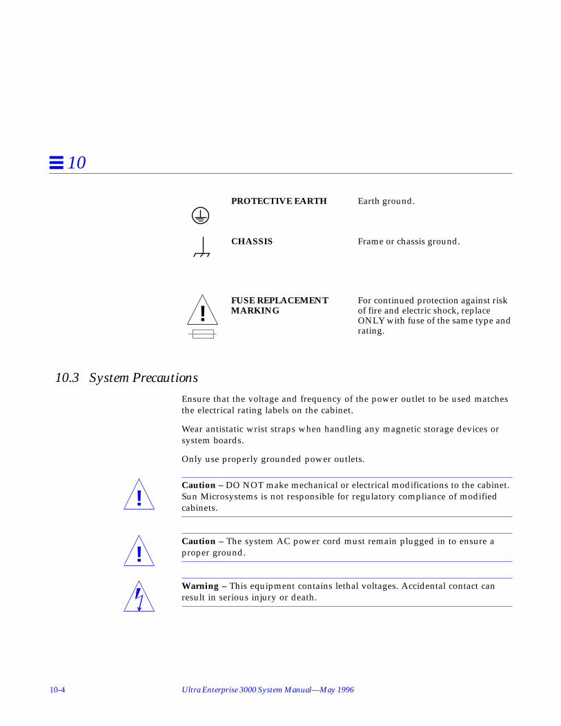
10-4 Ultra Enterprise 3000 System Manual—May 1996
10
PROTECTIVE EARTH Earth ground.
CHASSIS Frame or chassis ground.
FUSE REPLACEMENT For continued protection against riskMARKING of fire and electric shock, replace
ONLY with fuse of the same type andrating.
10.3 System PrecautionsEnsure that the voltage and frequency of the power outlet to be used matchesthe electrical rating labels on the cabinet.
Wear antistatic wrist straps when handling any magnetic storage devices orsystem boards.
Only use properly grounded power outlets.
Caution – DO NOT make mechanical or electrical modifications to the cabinet.Sun Microsystems is not responsible for regulatory compliance of modifiedcabinets.
Caution – The system AC power cord must remain plugged in to ensure aproper ground.
Warning – This equipment contains lethal voltages. Accidental contact canresult in serious injury or death.
!
!
!

Safety and Tools 10-5
10
Caution – Improper handling by unqualified personnel can cause seriousdamage to this equipment. Unqualified personnel who tamper with thisequipment may be held liable for any resulting damage to the equipment.
Persons who remove any of the outer panels to access this equipment mustobserve all safety precautions and ensure compliance with skill levelrequirements, certification, and all applicable local and national laws.
All procedures contained in this document must be performed by qualifiedservice-trained maintenance providers.
Caution – Before you begin, carefully read each of the procedures in thismanual. If you have not performed similar operations on comparableequipment, do not attempt to perform these procedures.
10.4 Tools RequiredThis list represents the minimum of tools and test equipment required toservice the system cabinet:
• Screwdriver, Phillips #2• Screwdriver, Phillips #1• DIP/IC extraction tool• ESD mat• Grounding wrist strap• Needlenose pliers• Hex driver, 3/32
!
!

10-6 Ultra Enterprise 3000 System Manual—May 1996
10

11-1
Powering Off and On 11
This chapter contains information necessary to prepare the system forservicing. Included are system power off and on, and external cable removalprocedures.
11.1 Powering Off the SystemBefore turning off system power, halt the operating system as shown below.Failure to halt the operating system properly can cause the loss of disk drivedata.
If you are troubleshooting system problems, you may find it convenient toreset the system or even cycle system power from the console. See Section 8.6.2,“Using a Remote Console,” on page 8-13.
1. Notify users that the system is going down.
2. Back up the system files and data to tape, if necessary.
3. Halt the system using the appropriate commands. Refer to the SolarisHandbook for SMCC Peripherals that corresponds to your operating system.
Powering Off the System page 11-1
Removing the External Cables page 11-3
Restarting the System page 11-4
Reading Boot Messages page 11-6

11-2 Ultra Enterprise 3000 System Manual—May 1996
11
4. Wait for the system-halted message and the boot monitor prompt.
5. Use the handle on the front of the Enterprise 3000 system and pull thefront door open.
6. Locate the system keyswitch in the upper right corner, and turn the keyswitch to the Standby position (fully counterclockwise).See Figure 11-1.
7. Turn the AC power switch on the system rear off.This switch is on the peripheral power supply/AC that is installed in the farleft corner. See Figure 11-2.
Figure 11-1 Keyswitch Standby Position
Standby

Powering Off and On 11-3
11
Figure 11-2 AC Power Switch and Power Receptacle
11.2 Removing the External Cables1. Position the server for easy access to the rear.
2. Disconnect each cable from the I/O boards carefully.Squeeze the locking tabs on the sides of the connector body, or loosen anyretaining screws (if provided), and pull the connectors out.
3. Mark each cable for identification as you remove it.
4. Remove any cable restraints.
5. Clear the cables away from the server.
AC connector
AC power switch

11-4 Ultra Enterprise 3000 System Manual—May 1996
11
11.3 Restarting the System
Note – As the system starts up, watch for error messages from the POSTdiagnostic program. If a terminal is not already part of the system, install aTTY terminal before continuing the start up. See the Ultra Enterprise 3000System Installation Guide.
1. Use the handle on the front of the Ultra Enterprise 3000 system and pullthe front door open.
2. Locate the system keyswitch in the upper right corner, and turn the keyswitch to the standby position ( ).See Figure 11-1.
Caution – The outlet must be a 100-120 or 200-240 VAC 30-ampere circuit,intended solely for use by the server, as described in the site preparationinstructions in the Ultra Enterprise 3000 System Installation Guide. The electricalreceptacle must be grounded, and the grounding conductor serving thisreceptacle must be connected to the earth ground at the service equipment.
3. Turn on the AC power sequencer power switch.See Figure 11-2.
4. Turn on power to the terminal.A terminal is required for viewing system messages. For setup instructions,see Section 8.1, “Using a Terminal,” on page 8-1.
5. Turn the key switch to the power-on position ( ).See Figure 11-1. Several things will happen:
• The left front panel LED (green) turns on immediately to indicate the DCpower supply is functioning.
• The middle front panel LED (yellow) lights immediately and should turnoff after approximately 60 seconds.
• The right front panel LED (green) flashes after POST has ended to showthat booting is successful and the operating system is running.
• The terminal screen lights up upon completion of the internal self test.
!

Powering Off and On 11-5
11
Warning – Never move the server or the expansion cabinets when systempower is on. Excessive movement can cause catastrophic disk drive failure.Always power the system OFF before moving cabinets.
6. Watch the terminal screen for any POST error messages.At the conclusion of testing, POST automatically configures the system,omitting any devices that have failed diagnostics. After POST ends, thesystem will boot using the new configuration.
Note – If the middle front panel LED (yellow) remains lit after the system hasbooted, the system has failed POST.
Note – POST does not test drives or internal parts of SBus cards. To test thesedevices, run OBP diagnostics manually after the system has booted. Refer tothe OpenBoot Command Reference manual for instructions.
7. To start POST again, or if the system hangs, press the CPU reset switch onthe clock board.See Figure 11-3.
!

11-6 Ultra Enterprise 3000 System Manual—May 1996
11
Figure 11-3 System Reset Switch on Clock Board
8. If the system displays “not responding” or “no carrier” messages, theLink Integrity Test may be set incorrectly. See “Link Integrity Test” onpage 4-20.
11.4 Reading Boot Messages♦ Use the boot software messages to verify the presence of options in the
system. After POST completes the system self-test, a message similar tothe following will appear on your screen. The message lists hardwaredetected in the system.
System resetbutton
Powering Off and On 11-7
11
Note – The following screen display is only an example. The actual messagedisplayed on the screen will vary with the software running on the system.
If there is no terminal on this system, you must check the system status byinspecting LEDs on the front panel. See Figure 11-4.
Figure 11-4 Front Panel Status LEDs
Table 11-1 summarizes the front panel LED status conditions during and afterPOST.
4-slot Ultra Enterprise 3000, Keyboard PresentOpenBoot -.- FCS, --- MB memory installed, Serial #---.Ethernet address -:-:--:-:--:--, Host ID: ------.
DC power(green)
Fault (yellow)
System running (green)

11-8 Ultra Enterprise 3000 System Manual—May 1996
11
Table 11-1 LED Status Indicators
LED Condition
Left LED (green) On — DC power supply is receiving AC current.Off — There is no DC power.
Middle LED(yellow)
On flashing — (first 60 seconds) Self tests are running.Off — (after self tests end) No hardware failures.On — (after self tests end) Hardware failure was detected.
Right LED(green)
Off — (first 60 seconds) Self tests are running.On flashing— (after self tests end) System is running.Off — (after self tests end) System cannot run; repair is needed.

12-1
Preparing for Service 12
This chapter contains information about preparing the system for service afterthe system has been powered off.
12.1 Servicing Hot-Pluggable ComponentsHot-pluggable components can be removed and replaced without powering offthe system. For information about disconnecting and connecting hot-pluggablecomponents that require service, see Section 3.3, “Hot-Plug Feature,” onpage 3-3.
12.2 Powering Off the SystemSee Section 11.1, “Powering Off the System.”
Servicing Hot-Pluggable Components page 12-1
Powering Off the System page 11-1
Internal Access page 12-2
Restarting the System page 11-4

12-2 Ultra Enterprise 3000 System Manual—May 1996
12
12.3 Internal AccessThe system has a front bezel that must be removed to access the SCSI tray.
12.3.1 Front Bezel
To remove the front bezel:
1. Grasp the front bezel on both sides near the center.Place your thumbs on top of the front bezel and place your other fingers atthe slight indentations under the front bezel for leverage.
2. Pull the front bezel straight out toward you and set it aside.See Figure 12-1.
Figure 12-1 Removing the Front Bezel
To replace the front bezel, reverse these instructions.

Preparing for Service 12-3
12
12.3.2 SCSI Tray
To remove the SCSI tray:
1. Remove the front bezel.
2. Loosen the two captive screws securing the SCSI tray in the chassis.
3. Insert a screwdriver or similar instrument in the notch at the bottomcenter of the tray. Using the screwdriver, slightly pull out the tray.See Figure 12-2.
4. Grasp the SCSI tray and gently pull it from the chassis.Disconnect the cables from the back of the tray.
5. Remove the seven screws on top of the SCSI tray to lift off the tray coverto access CD and tape drives.
Figure 12-2 Removing the SCSI Tray
To replace the SCSI tray, reverse these procedures.

12-4 Ultra Enterprise 3000 System Manual—May 1996
12
12.4 Powering On the SystemSee Section 11.3, “Restarting the System,” to power on after all panels havebeen replaced.

A-1
Specifications A
A.1 Physical Specifications
Table A-1 System Physical Specifications
U.S. Metric
Height 25.5 in 64.5 cm
Width 17 in 43.2 cm
Depth 23.5 in 59.7 cm
Weight 160 lb, approx 72.7 kg, approx
Power cord 6 ft 1.8 m
Table A-2 Clearance and Service Access
U.S. Metric
Front 18 in 45.7 cm
Rear 18 in 45.7 cm
Left 6 in 15 cm
Right 6 in 15 cm

A-2 Ultra Enterprise 3000 System Manual—May 1996
A
A.2 Electrical Specifications
Table A-3 Shipping Specifications
U.S. Metric
Height 34 in 86 cm
Width 29 in 74 cm
Depth 22.5 in 57 cm
Weight 185 lb, approx 84 kg, approx
Table A-4 Server Electrical Specifications
Parameter Value
Input current Voltage range 100-120 Vac or 200-240 Vac
Current, maximum 8.5A
Current frequency range 47-63 Hz
Input power rating Total continuous power 750W
Volt-Ampere rating 825 VA
BTU rating 2600 BTU
Power factor 0.92 - 0.96
Plug type U.S. NEMA 5-15P
International 10A, single phase IEC 320, C14

Specifications A-3
A
A.3 Environmental Requirements
Table A-5 Temperature, Humidity, and Altitude Limits
Operating Nonoperating
Temperature 41F to 104F (5C to 40C) -4F to 140F (-20C to 60C)
Humidity 20% to 80% RH noncondensing,27C max wb
93% RH
Altitude 9,843 ft (3 km) 39,370 ft (12 km)

A-4 Ultra Enterprise 3000 System Manual—May 1996
A

B-1
Functional Description B
The 4-slot Enterprise 3000 server is part of the Ultra Enterprise X000 serverfamily, which includes the 16-slot and 8-slot cabinet servers and an 8-slotstandalone server.
All systems feature shared-memory multiprocessors and use the same boards,power/cooling modules (PCMs), and operating software.
B.1 System PackagingThis section describes the standalone enclosure. See Figure B-1.
The front of the cabinet contains the CD-ROM/tape drives, the keyswitch, theinternal disk drives, and the fan tray.
The rear of the cabinet contains the AC power switch, the peripheral powersupply, the clock board, the board slots, and the PCM slots. PCM slot 5 maycontain either an auxiliary fan tray or a spare PCM.
Air circulation inside the cabinet is provided by the fans in the power supplies.The PCMs have two fans each. The fans provide cooling for the power supplyitself, plus two adjacent board slots. PCM slot 5 must contain either a fan trayor a spare PCM. These fans cool the peripheral power supply.

B-2 Ultra Enterprise 3000 System Manual—May 1996
B
Figure B-1 4-Slot Enterprise 3000 Cabinet
All empty slots must be blocked by filler panels for proper airflow, cooling,and EMI protection.
B.1.1 Board Types
1. The CPU/Memory board supports up to two UltraSPARC CPU modulesand 16 SIMM slots.
2. The SBus I/O board includes two separate SBuses, each controlled by aseparate SYSIO ASIC. The board provides a total of three SBus slots forplug-in cards, two slots for fiber interface modules. The remaining slots areused for onboard devices.
SCSI CD-ROM/tape tray
Internal disks
Fan tray

Functional Description B-3
B
3. The Graphics I/O board provides an SBus with two SBus slots and severalonboard devices. This board also has a specialized slot for devices such asthe graphics (UPA) card, a high performance frame buffer.
The Enterprise X000 servers feature a high-speed (2.6 Gbyte per second)centerplane bus, which includes separate address and data buses.
Logically, there is no difference between board slots and each can accept anyboard type. However, whenever possible, I/O boards should be located on theback side of the centerplane for easy access to interface cables, which areusually routed to the rear of the cabinet.
Figure B-2 illustrates the bus structure of 4-slot Enterprise 3000 Server.
Figure B-2 Bus Structure
B.2 Board Hot-Swapping ProceduresThe CPU/Memory board and the I/O boards are hot-swappable under certainconditions. If the operating system detects a hardware failure in the board, thesystem powers down the corresponding board slot and turns off the left greenstatus LED on the board. (There are three status LEDs on each board. SeeTable 8-2 for the board LED codes.)
Address bus
Data bus
CPU/Memory board
CPU 1
CPU 0
8x Datacontroller
Addresscontroller
MemoryI/O board
SBus 1SYSIO 1
SYSIO 0SBus 0
8x Datacontroller
Addresscontroller

B-4 Ultra Enterprise 3000 System Manual—May 1996
B
When the left green LED is off, it is safe to remove the board.
B.3 CPU/Memory BoardThe system will support up to three CPU/Memory boards.
The CPU/Memory board supports up to 2 CPU modules and 16 SIMMs. TheCPU/Memory board is shown in Figure B-3.
Figure B-3 CPU/Memory Board
All empty card cage slots must have a filler panel installed.
B.3.1 CPU Modules
Each CPU/Memory board has two sets of CPU connectors, marked PROC 0and PROC 1.
The order you fill CPU slots is not critical. However, to optimize heatdissipation in the system:
Board lock (x2)
Extractor lever (x2)
LEDs
CPU 0 slot
CPU 1slot

Functional Description B-5
B
• Fill all PROC 0 locations on all CPU/Memory boards before filling anyPROC 1 locations. To receive the maximum quantity of diagnosticinformation, fill PROC 0 on board 0.
• After all PROC 0 locations are filled, you may begin filling the PROC 1locations, again starting from the lowest slot number to the highest.
Table B-1 shows slot locations for the example of five CPUs on threeCPU/Memory boards. Note that slot 1 is reserved for the I/O board.
B.3.2 System Master
The board slots are interchangeable. A system master board is selected for theduration of POST and OBP testing, to control the testing processes. The systemmaster is normally the lowest-numbered slot containing a board with afunctional CPU. After the tests are finished, the board slots are again fullyequivalent.
B.3.3 SIMMs
The CPU/Memory board has 16 slots for SIMMs, organized as two banks ofeight SIMMs.
B.3.3.1 Slot Locations
SIMMs must be installed in full banks of eight. Figure B-4 shows the slotnumbers for bank 0 and bank 1.
Table B-1 Locations for Five CPUs on Three Boards
Board Slot Number PROC 0 PROC 1
3 in in
5 in in
7 in —

B-6 Ultra Enterprise 3000 System Manual—May 1996
B
Figure B-4 SIMM Slot Locations
B.3.3.2 SIMM Selection
The JEDEC standard 3.3 volt SIMMs are available in 8, 32, or 128 Mbytecapacities. All are 168-pin SIMMs.
Do not mix different capacities in a bank.
B.4 I/O BoardsTwo types of I/O boards are available:
• The SBus I/O board has three SBus connectors. A dual-wide SBus card canbe mounted using two of the connectors.
• The Graphics I/O board has two SBus slots and one universal peripheraladapter (UPA) connector. This board does not accept a dual-wide SBus card.
CPU slot
CPU slot
Key: B1 = bank 1B0 = bank 0,
B1 - J3801
B1 - J3701
B1 - J3601
B1 - J3501
B1 - J3401
B1 - J3301
B1 - J3201
B1 - J3101
B0 - J3800
B0 - J3700
B0 - J3600
B0 - J3500
B0 - J3400
B0 - J3300
B0 - J3200
B0 - J3100

Functional Description B-7
B
An I/O board should be present in slot 1. This is the only slot that allowsaccess to internal SCSI devices.
B.4.1 SBus I/O Board
The SBus version of the I/O board includes two SYSIO ASICs. Each ASICprovides two SBuses. Three SBus slots are available on this board for plug-inboards. The remaining SBus slots are used for onboard devices such as 10/100Mbyte/second twisted-pair Ethernet, Fast/Wide SCSI, Fibre Channelinterfaces. See Figure B-5.
Figure B-5 SBus I/O Board
All empty card cage slots must have a filler panel installed.
SBus slot 0
SBus slot 1
SBus slot 2
Fiber interface 1
Fiber interface 0
Twisted-pair Ethernet
Fast wide SCSI
MII external transceiver

B-8 Ultra Enterprise 3000 System Manual—May 1996
B
B.4.2 Graphics I/O Board
The graphics version of the I/O board includes one UPA-64 Slave Frame Bufferand one SYSIO ASIC that provides one SBus for two SBus slots for two plug-incards. The remaining SBus slots are used for onboard devices such as 10/100Mbyte/second twisted-pair Ethernet, Fast/Wide SCSI, Fibre Channelinterfaces. See Figure B-6.
Figure B-6 Graphics I/O Board
All empty card cage slots must have a filler panel installed.
B.5 Power/Cooling ModulesThe system has a maximum capacity of three power/cooling modules (PCMs).The PCM slots are not numbered.
The PCMs also provide cooling air for the boards. The slot above any boardmust have a PCM to provide cooling air.
SBus slot 0
UPA slot
SBus slot 2
Fiber interface 1
Fiber interface 0
Twisted-pair Ethernet
Fast wide SCSI
MII external transceiver

Functional Description B-9
B
The slot above the peripheral power supply may have either a PCM or a fantray.
These PCMs are all of the same type, and current from an individual PCM isavailable to the entire centerplane.
There must be at least one PCM for every two boards.
With automatic system reconfiguration (ASR), you can hot-plug a PCM if thereis a spare PCM. That is, while a PCM is out of the system, the remaining PCMsmust be able to provide sufficient airflow and electrical power.
B.6 Peripheral Power Supply/ACThe system has one peripheral power supply/AC input (PPS/AC). ThePPS/AC has the AC switch and AC cable socket. The PPS/AC is also known tothe system software as PPS 0.
The peripheral power supply provides DC power for the CD-ROM/tape trayand precharge power for hot-plugging boards and PCMs.
Figure B-7 Peripheral Power Supply/AC
To the right of the PPS/AC is a slot for an optional auxiliary peripheral powersupply (PPS). The PPS is also known to the system software as PPS 1.The PPSsupplies redundant current for the peripheral devices.

B-10 Ultra Enterprise 3000 System Manual—May 1996
B
Figure B-8 Locations of the PPS/AC and PPS
The PPS is also used in the larger 16-slot and 8-slot Enterprise X000 servers. Inthe Enterprise 3000 server, only the PPS/AC provides precharge current for thehot-plug function.
B.7 Clock BoardThe clock board (see Figure B-9) is located at the right side of the card cage.
The clock board receives cooling air from the PCM located above the twoboard slots on the right side of the card cage.
The clock board provides 16 pairs of system clocks, 32 pairs of processorclocks.
The processor clock frequency is set to match the lowest-frequency processor inthe system. All processors run at the same clock speed. The system clock andthe processor clocks are derived from a single clock source. The frequency ofthe clock source as well as the processor and system clocks are programmableand set by firmware.
PPS/AC
PPS (optional)

Functional Description B-11
B
The clock board also includes central devices including serial ports, keyboardand mouse, and a time of day (TOD) chip.
Figure B-9 Clock Board
B.8 Network InterfacesEach I/O board has an onboard Ethernet circuit, connected to an RJ-45 twisted-pair connector and a 40-pin media independent interface (MII) connector. Thecircuit automatically adapts to 10 Mbit or 100 Mbit at the twisted-pair port. The100 Mbit MII connector accepts external Ethernet transceivers. If a transceiveris attached to the MII connector, the twisted-pair connector is disabled.
Ethernet SBus interface cards may also be added to one or more I/O boards foradditional networks.
B.9 Internal Disk DrivesThe 4-slot standalone Enterprise 3000 server has a capacity of 10 internal SCSIdisk drives. SCSI ID addresses are set automatically and are determined by slotlocation.

B-12 Ultra Enterprise 3000 System Manual—May 1996
B
B.10 CD-ROM/Tape DriveThe SCSI tray at the front of the system accepts two optional SCSI drives, suchas CD-ROM and tape drives. See Appendix C for SCSI ID addressing.
B.11 Expansion CabinetsThe Enterprise 3000 system supports Fibre Channel and differential SCSIinterface disk storage options.

C-1
SCSI Devices C
C.1 SCSI Target ID Number Addressing
C.1.1 SCSI Drive Tray
The default SCSI ID numbers for devices in the SCSI tray are:
C.1.2 Internal Disk Drives
The default SCSI ID numbers for internal disk drives are:
Table C-1 SCSI Tray Default SCSI ID Numbers
Device ID
CD-ROM drive 6
Tape drive 5
Table C-2 Internal Disk Drive Default SCSI ID Numbers
Drive Slot ID Number
0 0
1 1
2 2
3 3

C-2 Ultra Enterprise 3000 System Manual—May 1996
C
C.2 Device Naming ConventionsSCSI devices are identified by path names or aliases.
A full path name can be of the form, /sbus@1f,0/cgsix@1,0 .
A short path name does not include address information. For example, the fullpath name shown above can be shortened to /sbus/cgsix . This form of namecan be ambiguous if more than one of the devices is installed.
An alias is another form of short name. Some common aliases are:
Use the OpenBoot devalias command to list current aliases.
10 10
11 11
12 12
13 13
14 14
15 15
Table C-3 Examples of Alias Names
Alias Full Path Name
net /sbus@3,0/SUNW,hme@3,8c00000
cdrom /sbus@3,0/SUNW,fas@3,8800000/sd@6,0:f
ttya /central/fhc/zs@0,902000:a
ttyb /central/fhc/zs@0,902000:b
screen /SUNW,ffb@2,0
Table C-2 Internal Disk Drive Default SCSI ID Numbers (Continued)
Drive Slot ID Number

SCSI Devices C-3
C
C.3 SCSI Cable LengthDo not attach any external SCSI devices to the onboard SCSI connector of theI/O board in card cage slot 1. To add external SCSI devices, use the SBus slotson the I/O board, or add a second I/O board.
The maximum combined length for a string of SCSI cables is six meters fornon-differential cables. For differential SCSI cables, the maximum is 25 meters.
The maximum combined length for a string of SCSI cables is six meters fornon-differential cables. For differential SCSI cables, the maximum is 25 meters.
To calculate the total length of a SCSI string, include external cables, internalcables, and printed traces. Table C-4 lists measurements for Enterprise servers.
C.4 SCSI TerminationThe I/O board in slot 1 of any Enterprise server must be terminated. This slotconnects to the internal SCSI disk drives and the optional internal CD-ROMand tape drives.
The SCSI bus on an I/O board in any other slot must be terminated only ifSCSI devices are connected to that board.
Table C-4 Internal SCSI Lengths (Approximate)
Location Internal Length
SBus I/O board 0.43 meter
Graphics I/O board 0.43 meter

C-4 Ultra Enterprise 3000 System Manual—May 1996
C

D-1
Rules for System Configuration D
Some of the following rules are suggestions for optimizing your system. Otherrules are strictly required and are marked with the notation: (Requirement) or(Maximum).
D.1 Card CageIn the card cage, board slots are numbered from right to left: 1, 3, 5, and 7.1 SeeFigure D-1.
In most respects, all four board slots in the card cage are interchangeable.However, slot 1 is the only slot that is physically connected in the card cage tothe SCSI bus on the centerplane. Slot 1 is therefore normally reserved for anI/O board, since the CPU/Memory board does not have a SCSI bus controller.
The centerplane SCSI bus connects to the ten internal disk drive slots and(through a SCSI cable) to the SCSI CD-ROM/tape drive tray.
1. This unconventional numbering system is derived from the slot numbering used in the general card cagedesign of the Enterprise server family. The Enterprise 3000 server card cage is based on the Enterprise 4000card cage, which is double-sided, with even-numbered slots (0, 2, 4, 6) on the front and odd-numbered slots(1, 3, 5, 7) on the back. The Enterprise 3000 card cage uses the system internal SCSI bus (slot 1), which in turndictated the use of the back half of the Enterprise 4000 card cage design.

D-2 Ultra Enterprise 3000 System Manual—May 1996
D
D.2 I/O Boards1. An I/O board must always be in slot 1. This is the only slot that allows
direct access to the internal SCSI devices. (Requirement)
2. Up to three graphics (UPA) cards are supported in a system. (Maximum)
3. The SCSI bus on the I/O board in slot 1 must be terminated because itconnects to the internal system SCSI bus. (Requirement)
4. An I/O board in a slot other than slot 1 does not require termination if nodevices connect to the SCSI bus on that board.
Figure D-1 Board Slots and Power Supply Locations
5 3 1Clock board
7
System rear view
PCM
PCM or
Peripheral
(Optional)
power supply/
power supply
auxiliaryfan tray
auxiliary peripheral
Board slots:
AC input

Rules for System Configuration D-3
D
D.3 CPU/Memory Boards1. When configured at the factory, a CPU/Memory board is installed in the
second slot (slot 3) of the four board slots. See Figure D-1. As noted earlier,slot 1 is reserved for an I/O board.
2. The Enterprise 3000 server supports up to three CPU/Memory boards.(Maximum)
D.4 Power Supplies and Fan Cooling1. If you add a CPU/Memory board or I/O board to the card cage, the slot
directly above the board must contain a power/cooling module (PCM).(Requirement.) If necessary, install a PCM in that slot. The fans in the PCMare the only source of cooling air for the board slot.
2. All unused slots must contain a filler panel to avoid loss of cooling air.(Requirement)
3. Under some circumstances, you can remove a PCM from an active systemfor a short time. However, if the boards in the adjacent slots create largequantities of heat, it is safer to halt and power down the system first.
4. The peripheral power supply/AC input (PPS/AC) must be fully functionalif you replace a hot-pluggable board or PCM. (Requirement.) Only thePPS/AC provides precharge current to the system. If the PPS/AC cannotsupply precharge current, the hot-pluggable module will be damaged.
5. The slot above the PPS/AC must contain either a PCM or an auxiliary fantray. (Requirement)
6. The auxiliary peripheral power supply (PPS 1) is an option. The PPS 1 islocated to the right of the PPS/AC. If a PPS 1 is not present, the slot containsa filler panel.
7. PPS 1 does not provide precharge current.
D.5 Filler Panels1. Board filler panels are required for all unused board slots. (Requirement)
2. PCM filler panels are required for all unused PCM bays. (Requirement)

D-4 Ultra Enterprise 3000 System Manual—May 1996
D
D.6 SBus Cards1. Only the SBus I/O board accepts a double-wide SBus card (in SBus slots 1
and 2). The location of SBus slot 0 prevents its use with double-wide cards.
2. The Graphics I/O board does not accept double-wide SBus cards. Themiddle card connector does not fit SBus cards.
D.7 CPU Modules1. Each CPU/Memory board has two sets of CPU connectors, marked PROC 0
and PROC 1.
2. Do not mix CPU speeds—all CPUs run at the lowest common frequency.
3. The order you fill CPU slots is not critical. However, to optimize heatdissipation in the system:• Fill all PROC 0 locations on all CPU/Memory boards before filling any
PROC 1 locations. To receive the maximum quantity of diagnosticinformation, fill PROC 0 on board 0.
• After all PROC 0 locations are filled, you can begin filling the PROC 1locations, again starting from the lowest slot number to the highest.
Table D-1 shows slot locations for an example of five CPUs on threeCPU/Memory boards.
D.8 Memory Modules1. The SIMMs are 168-pin, JEDEC-standard devices. Do not use other types of
memory modules.
2. Do not mix 8, 32, or 128 Mbyte SIMMs in the same bank. (Requirement.) AllSIMMs in a bank (eight SIMMs) must have the same capacity.
Table D-1 Example of CPU Placement
Slot Number PROC 0 PROC 1
3 in in
5 in in
7 in —

Rules for System Configuration D-5
D
3. Note that two banks of SIMM slots on a CPU/Memory board areinterleaved. A bank is composed of eight alternating SIMM slots.
4. All SIMMs in a bank should have the same speed rating. If SIMMs ofdifferent speeds are mixed in a bank, the bank will function, but at thelowest speed.
D.9 Cabling
D.9.1 SCSI
1. Do not attach any external SCSI devices to the onboard SCSI connector ofthe I/O board in card cage slot 1. (Requirement)
2. To add external SCSI devices, use the SBus slots on the I/O board, or add asecond I/O board. You may use either an SBus I/O board or a Graphics I/Oboard.
3. The maximum length for a chain of single-ended (non-differential) SCSIcables is 6.0 meters (20 feet). (Maximum)
4. The maximum length for a chain of differential SCSI cables is 25 meters (82feet). (Maximum)
D.9.2 Ethernet
1. The main Ethernet should be connected to the I/O board in slot 1.
2. Each I/O board has one Ethernet circuit with both TPE and MII connectors.Only one type of connector may be used at a time.
3. After slot 1 is connected to a network, additional Ethernet connections maybe made to I/O boards or SBus cards in any other card cage slot.
D.9.3 Video Interface
1. A system that is operated with a monitor can use a graphics adaptermounted on either a Graphics I/O board or an SBus I/O board. The SunCreator and Creator 3D Graphics I/O boards are available.
2. Up to three Graphics I/O boards are supported in a system.

D-6 Ultra Enterprise 3000 System Manual—May 1996
D
D.10 CD-ROM/Tape Drive SCSI TrayThe SCSI tray is located at the upper front of the cabinet. Various CD-ROM andtape drive options are available. A SCSI cable connects the tray to card cageslot 1 on the centerplane.
D.11 Disk DrivesDisk drive slots are located at the front of the cabinet. In the upper row, thedisk drive slot numbers are 0, 1, 2, and 3, numbered from left to right. SeeFigure D-2.
To avoid potential numbering conflicts on the wide SCSI bus, disk drives in thelower row are numbered 10 through 15. Slot 10 is at the left, followed at theright by slots 11, 12, 13, 14, and 15.
All disk drives connect through the centerplane to the SCSI bus of card cageslot 1.
Figure D-2 Disk Drive Slot Numbers
0 1 2 3
10 11 12 13 14 15

E-1
Non-Chassis Field ReplaceableUnits (FRUs) E
See the following pages to remove and replace system subassemblies:
Table E-1 List of Field Replaceable Units
FRU List Items Part Number Page Number
Assembly, cable, SCSI tray data 530-2220 page E-10
Assembly, cable, power, DC 530-2221 page E-10
Assembly, cable, key switch PWBcenterplane
530-2226 page E-11
Centerplane 501-2939 page E-18
Fan tray assembly 540-2756 page E-2
Fan tray assembly, auxiliary 540-2757 page E-3
Key switch lock cable assembly 530-2148 page E-14
LED board 501-2599 page E-17

E-2 Ultra Enterprise 3000 System Manual—May 1996
E
E.1 Fan Tray Assembly
To remove the fan tray assembly:1. Pull open the front door of the Enterprise 3000 system.
2. Locate the fan tray assembly at the bottom of the system.
3. Loosen the three captive screws securing the fan tray assembly in thechassis.See Figure E-1.
Figure E-1 Removing the Fan Tray Assembly
Captivescrews

Non-Chassis Field Replaceable Units (FRUs) E-3
E
4. Gently pull the fan tray assembly from the chassis and set it aside.
To replace the fan tray assembly:1. Gently insert the fan tray assembly in the bottom of the Enterprise 3000
system.See Figure E-1.
Caution – DO NOT FORCE the fan tray assembly into the slot; this can causedamage to the fan tray assembly and system.
The fan tray assembly should insert and seat smoothly. If it binds, remove it,and inspect the slot for any obvious obstructions. Do not damage thespringfingers at the bottom of the fan tray assembly.
2. Tighten the three captive screws securing the fan tray assembly to thechassis.
3. Close the front door of the Enterprise 3000 system.
E.2 Auxiliary Fan Tray Assembly
To remove the auxiliary fan tray assembly:1. Locate the auxiliary fan tray assembly at the back of the system.
Viewed from the rear of the system, the auxiliary fan tray is on the upperleft side of the chassis.
2. Release the auxiliary fan tray from the system chassis by inserting aPhillips #1 screwdriver into each quarter-turn access slot and turning tothe unlocked position.See Figure E-2.
!

E-4 Ultra Enterprise 3000 System Manual—May 1996
E
Figure E-2 Unlocking and Locking Quarter-Turn Access Slots
3. Pull the end of the extraction lever outward to release the auxiliary fantray assembly from the centerplane.See Figure E-3.
Figure E-3 Removing the Auxiliary Fan Tray

Non-Chassis Field Replaceable Units (FRUs) E-5
E
4. Slowly remove the auxiliary fan tray assembly from the chassis and set itaside.
To replace the auxiliary fan tray assembly:1. Carefully insert the auxiliary fan tray into the slot at the back of the
Enterprise 3000 system.• Ensure that the extraction lever is in the outward position.• Orient the auxiliary fan tray with the extraction lever on the outside edge
of the Enterprise 3000 system.See Figure E-3.
2. Slide the auxiliary fan tray assembly toward the centerplane.The auxiliary fan tray assembly will not seat fully unless the lever is in thisstarting position.
Caution – DO NOT FORCE the auxiliary fan tray assembly into the slot; thiscan cause damage to the auxiliary fan tray and system.
The auxiliary fan tray assembly should insert and seat smoothly. If it binds,remove it, and inspect the slot for any obvious obstructions. Do not damagethe springfingers at the bottom of the auxiliary fan tray assembly.
3. Swing the extraction lever inward to the locked position to seat theauxiliary fan tray assembly.Do not press on the front panel of the auxiliary fan tray assembly to seat it;doing so will damage the connector pins.
4. Lock the auxiliary fan tray to the system chassis by inserting a Phillips #1screwdriver into each quarter-turn access slot and then turning to thelocked position.See Figure E-2.
E.3 Removing the Front and Side PanelsComplete the following section as a prerequisite if you are removing one of thefollowing subassemblies:
• SCSI tray data and DC power cable assemblies• Key switch PWB centerplane cable assembly• Key switch lock cable assembly• LED board
!

E-6 Ultra Enterprise 3000 System Manual—May 1996
E
• Centerplane
To remove the side panels and front bezel:1. Completely power off the Enterprise 3000 system.
See the power-off instructions in Chapter 11, “Powering Off and On.”
2. Remove the side panels.
• Grasp the bottom of the side panel in the center and pull the panel outslightly until the snap disengages.
• Simultaneously lift the side panel up and out.
See Figure E-4.
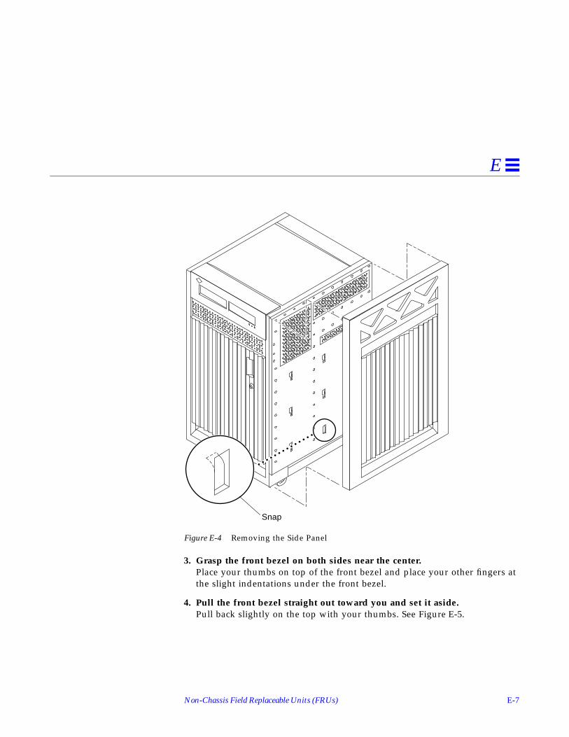
Non-Chassis Field Replaceable Units (FRUs) E-7
E
Figure E-4 Removing the Side Panel
3. Grasp the front bezel on both sides near the center.Place your thumbs on top of the front bezel and place your other fingers atthe slight indentations under the front bezel.
4. Pull the front bezel straight out toward you and set it aside.Pull back slightly on the top with your thumbs. See Figure E-5.
Snap

E-8 Ultra Enterprise 3000 System Manual—May 1996
E
Figure E-5 Removing the Front Bezel
To remove the SCSI tray and front decorative panel:1. Loosen the two captive screws securing the SCSI tray in the chassis.
2. Insert a screwdriver or similar instrument in the notch at the bottomcenter of the SCSI tray. Using the screwdriver, slightly pull out the SCSItray.
3. Grasp the SCSI tray and gently pull it from the chassis.See Figure E-6.

Non-Chassis Field Replaceable Units (FRUs) E-9
E
Figure E-6 Removing the SCSI Tray
Note – If you are not replacing the SCSI cables or the centerplane, you maysimply flip over the SCSI tray and rest it on the top of the Enterprise 3000system.
4. If you are replacing SCSI cables or the centerplane, disconnect the cablesfrom the back of the SCSI tray.
5. Open the front door of the Enterprise 3000 system.• If you are replacing the centerplane, go to Section E.3.5, “Centerplane,” on
page E-18.• Otherwise, continue with Step 6.
Power cables
SCSI cable
Bottom opening
E-10 Ultra Enterprise 3000 System Manual—May 1996
E
6. Remove the screws securing the front decorative (perforated) panel in thechassis.There are eight screws on the top, seven screws on the bottom, and threescrews on each side of the front decorative panel.
7. Grasp the front decorative panel and set it aside.
E.3.1 SCSI Tray Data and DC Power Cable Assemblies
To remove the data and power cables:1. Remove the panels covering the data and power cables.
Complete the steps in Section E.3, “Removing the Front and Side Panels.”
2. Reach through the space previously occupied by the front decorative(perforated) panel and disconnect the SCSI cables from the centerplane.
3. Cut the cable ties that secure the cables to the chassis.
4. Remove the cables.
To replace the data and power cables:1. Connect the cables to the back of the SCSI tray.
Note – The SCSI data and power cables are keyed so that the cables fit into theconnectors in only one direction and cannot be reversed.
2. Place the cables through the chassis opening vacated by the SCSI tray.Drop the cables through the bottom opening.The cables should be visible through the opening normally covered by thefront decorative (perforated) panel. See Figure E-6.
3. Reach through the space normally covered by the front decorative paneland connect the cables to the centerplane.See Figure E-7.

Non-Chassis Field Replaceable Units (FRUs) E-11
E
Figure E-7 Cable Connectors on the Centerplane
4. Replace the panels covering the data and power cables.Complete the steps in Section E.4, “Replacing the Front and Side Panels.”
E.3.2 Key Switch PWB Centerplane Cable Assembly
To remove the key switch PWB centerplane cable assembly:1. Remove the panels covering the key switch printed wiring board (PWB)
centerplane cable.Complete the steps in Section E.3, “Removing the Front and Side Panels.”
SCSI traydata cableconnector
SCSI DC powercable connector
Key switch PWBcenterplane cableconnector

E-12 Ultra Enterprise 3000 System Manual—May 1996
E
2. Disconnect the key switch PWB centerplane cable from the centerplane.See Figure E-8.
Figure E-8 Key Switch PWB Centerplane Cable
3. Disconnect the key switch PWB centerplane cable from the LED board.
a. Pull forward on the two locking tabs securing the cable to the LEDboard.The key switch PWB centerplane cable is in back of the key switch lockcable assembly. See Figure E-9.
Key switch PWBcenterplane cable

Non-Chassis Field Replaceable Units (FRUs) E-13
E
Figure E-9 Locking Tabs on the LED Board
b. Disconnect the cable.
4. Cut the cable tie and remove the key switch PWB centerplane cable.
To replace the key switch PWB centerplane cable assembly:
Note – Both ends of the key switch printed wiring board (PWB) centerplanecable are keyed so that the cable fits into the connector in only one directionand cannot be reversed.
1. Connect the key switch PWB centerplane cable to the LED board.
a. Connect the cable.The key switch PWB centerplane cable is in back of the key switch lockcable assembly. See Figure E-8.
b. Push back on the two locking tabs and secure the cable to the LEDboard.The two locking tabs fit over the connector, securing the key switch PWBcenterplane cable to the LED board. See Figure E-9.
2. Connect the other end of the key switch PWB centerplane cable to thecenterplane.
3. Use a cable tie and secure the key switch PWB centerplane cable to thechassis.
Locking tabs forPWB centerplanecable
Locking tabs for keyswitch lock cable

E-14 Ultra Enterprise 3000 System Manual—May 1996
E
4. Replace the panels covering the key switch lock assembly.Complete the steps in Section E.4, “Replacing the Front and Side Panels.”
E.3.3 Key Switch Lock Cable Assembly
To remove the key switch lock cable assembly:1. Remove the panels covering the key switch lock cable assembly.
Complete the steps in Section E.3, “Removing the Front and Side Panels.”
2. Disconnect the key switch lock cable from the LED board.
a. Pull forward on the two locking tabs securing the cable to the LEDboard.The key switch lock cable is in front of the key switch PWB centerplanecable. See Figure E-9.
b. Disconnect the cable.
3. Remove the two screws that attach the key switch lock assembly to thechassis.
4. Twist the key switch lock assembly to the left and pull it forward and outaway from the chassis.The key switch lock assembly has a hook that sits on the bracket in thechassis. You need to turn the assembly so that the hook clears the bracketbefore the key switch lock assembly can be removed. See Figure E-10.

Non-Chassis Field Replaceable Units (FRUs) E-15
E
Figure E-10 Removing the Key Switch Lock Cable Assembly
5. Separate the key switch lock cable from the key switch bracket.
a. Remove the U-shaped key switch keeper by pulling it straight outaway from the key switch lock assembly.The key switch keeper is located on the inside of the key switch bracketand secures the cable to the bracket.
b. Remove the key switch lock cable by pulling it through the keyhole.See Figure E-10.
Screws
Key switch lockcable assembly
Hook
Key switchbracket

E-16 Ultra Enterprise 3000 System Manual—May 1996
E
To replace the key switch lock cable assembly:1. Secure the key switch lock cable to the key switch bracket.
a. Insert the key switch lock cable into the keyhole of the key switchbracket.Position the key switch lock cable so that the arrow on the front of thecable assembly is turned upward. See Figure E-10.
b. Secure the key switch lock cable to the bracket using the key switchkeeper.Slip the key switch keeper into the groove on the cable to secure the cableto the bracket.
2. Twist the key switch lock assembly to the left and thread it through theround hole in the right front side of the chassis.
3. Twist the key switch lock assembly to the right so that the hook rests onthe bracket in the chassis.See Figure E-10.
4. Replace the two screws that attach the key switch lock assembly to thechassis.
5. Connect the key switch lock cable to the LED board.
Note – The key switch lock cable is keyed so that the cable fits into theconnector in only one direction and cannot be reversed.
a. Connect the cable.The key switch lock cable is in front of the key switch PWB centerplanecable. See Figure E-9.
b. Push back on the two locking tabs and secure the cable to the LEDboard.The two locking tabs fit over the connector, securing the key switch lockcable assembly to the LED board.
6. Replace the panels covering the key switch lock assembly.Complete the steps in Section E.4, “Replacing the Front and Side Panels.”

Non-Chassis Field Replaceable Units (FRUs) E-17
E
E.3.4 LED Board
Note – Use a short Phillips screwdriver to complete this procedure.
To remove the LED board:1. Remove the panels covering the LED board.
Complete the steps in Section E.3, “Removing the Front and Side Panels.”
2. Disconnect the key switch lock and PWB centerplane cables from the LEDboard.See Figure E-9.
a. Pull forward on the two locking tabs securing the cables to the LEDboard.
b. Disconnect the cables.
3. Remove the four screws securing the LED board to the chassis.There is one screw in each corner of the LED board.
4. Remove the LED board.
To replace the LED board:1. Orient the LED board so that the three LEDs are visible through the
chassis window cutout.
2. Insert a screw into the front right corner of the LED board.Use this screw as a guide and place the LED board against the chassis.
3. Slightly tighten the first screw and attach this corner of the LED board tothe chassis.
4. Replace the three other screws that attach the LED board to the chassis.
5. Tighten all four screws.
6. Connect the key switch lock and PWB centerplane cables to the LEDboard.See Figure E-9.

E-18 Ultra Enterprise 3000 System Manual—May 1996
E
Note – The key switch lock and PWB centerplane cables are keyed so that thecables fit into the connectors in only one direction and cannot be reversed.
a. Connect the cables.The key switch lock cable is in front of the key switch PWB centerplanecable.
b. Push back on the locking tabs and secure the cables to the LED board.The two locking tabs fit over the connector, securing the cable assemblyto the LED board.
7. Replace the panels covering the LED board.Complete the steps in Section E.4, “Replacing the Front and Side Panels.”
E.3.5 Centerplane
To remove the Centerplane:1. Remove the panels covering the front of the chassis.
Complete the steps in Section E.3, “Removing the Front and Side Panels.”
2. Remove all the disk drives.See Chapter 7, “Internal SCSI and Storage Devices,” for information onremoving disk drives.
3. Remove the fan tray assembly.See Section E.1, “Fan Tray Assembly,” for information on removing the fantray assembly.
4. Remove the 15 screws on each side that secure the front chassis to themain chassis.See Figure E-11.
5. Remove the two screws on the top front corners that secure the frontchassis to the main chassis.See Figure E-11.
6. Gently pull out the front chassis and set it aside.
7. Disconnect all the cables from the centerplane.

Non-Chassis Field Replaceable Units (FRUs) E-19
E
a. Disconnect the SCSI tray data and DC power cable assemblies.See Section E.3.1, “SCSI Tray Data and DC Power Cable Assemblies,” forinformation on disconnecting these cables.
b. Disconnect the key switch PWB centerplane cable assembly.See Section E.3.2, “Key Switch PWB Centerplane Cable Assembly,” forinformation on disconnecting this cable.
Figure E-11 Enterprise 3000 System Without the Front Chassis
15 screws
15 screws
2 screws

E-20 Ultra Enterprise 3000 System Manual—May 1996
E
8. Disconnect all the boards from the centerplane.See Chapter 3, “CPU/Memory Boards and Components,” Chapter 4, “I/OBoards and Components,” and Chapter 5, “Clock Board,” for information onremoving the boards.
9. Disconnect the peripheral power supplies from the centerplane.See Chapter 6, “Power Supplies,” for information on removing theperipheral power supplies.
10. Disconnect the PCMs from the centerplane.See Chapter 6, “Power Supplies,” for information on removing the PCMs.
11. If present, disconnect the auxiliary fan tray from the centerplane.See Section E.2, “Auxiliary Fan Tray Assembly,” for information onremoving the auxiliary fan tray.
12. If present, disconnect all the filler panels from the centerplane.
a. With a Phillips #1 screwdriver, turn the arrows to the unlockedposition in the quarter-turn access slots on the filler panels.See Figure E-2.
b. Pull out and disengage the filler panels from the centerplane.
13. From the front of the system, remove the 24 screws securing thecenterplane to the main chassis.
14. Remove the centerplane.
To replace the centerplane:1. Replace the 24 screws securing the centerplane to the main chassis.
2. Replace and secure the front chassis to the centerplane.Use the three guide pins to align the front chassis with the centerplane.

Non-Chassis Field Replaceable Units (FRUs) E-21
E
Figure E-12 Centerplane Guide Pins
3. Replace the two screws on the top front corners that secure the frontchassis to the main chassis.See Figure E-11.
4. Replace the 15 screws on each side that secure the front chassis to themain chassis.See Figure E-11.
5. Connect all the cables to the centerplane.
a. Connect the key switch PWB centerplane cable assembly.See Section E.3.2, “Key Switch PWB Centerplane Cable Assembly,” forinformation on connecting this cable.
b. Connect the SCSI tray data and DC power cable assemblies.See Section E.3.1, “SCSI Tray Data and DC Power Cable Assemblies,” forinformation on connecting these cables.
6. If present, connect the auxiliary fan tray to the centerplane.See Section E.2, “Auxiliary Fan Tray Assembly,” for information onreplacing the auxiliary fan tray.
Guide pins

E-22 Ultra Enterprise 3000 System Manual—May 1996
E
7. Connect the PCMs to the centerplane.See Chapter 6, “Power Supplies,” for information on replacing the PCMs.
8. Connect the peripheral power supplies to the centerplane.See Chapter 6, “Power Supplies,” for information on replacing theperipheral power supplies.
9. Connect all the boards to the centerplane.See Chapter 3, “CPU/Memory Boards and Components,” Chapter 4, “I/OBoards and Components,” and Chapter 5, “Clock Board,” for information onreplacing the boards.
10. Replace all the filler panels.
a. Slide the filler panels toward the centerplane.Ensure that the arrows in the quarter-turn access slots point to theunlocked position.
The filler panel should insert and seat smoothly. If it binds, remove it,and inspect the slot for any obvious obstructions.
b. With a Phillips #1 screwdriver, turn the arrows in the quarter-turnaccess slots to the locked position.See Figure E-2.
11. Replace all the disk drives.See Chapter 7, “Internal SCSI and Storage Devices,” for information onreplacing the disk drives.
12. Replace the fan tray assembly.See Section E.1, “Fan Tray Assembly,” for information on replacing the fantray assembly.
13. Replace the panels covering the front of the chassis.Complete the steps in Section E.4, “Replacing the Front and Side Panels.”
E.4 Replacing the Front and Side Panels
To replace the SCSI tray and front decorative panel:1. Replace the front decorative (perforated) panel.
There are eight screws on the top, seven screws on the bottom, and threescrews on each side of the front decorative panel.

Non-Chassis Field Replaceable Units (FRUs) E-23
E
2. Close the front door of the Enterprise 3000 system.
3. If necessary, connect the SCSI cables to the back of the SCSI tray.
4. Replace the SCSI tray into the chassis opening at the front of theEnterprise 3000 system.
5. Tighten the two captive screws securing the SCSI tray in the chassis.
To replace the front bezel and side panels:1. Place the front bezel against the chassis.
Press the panel into place.See Figure E-5.
2. Replace the side panels.
a. Place the side panel alongside the chassisThe top edge of the side panel should be approximately 1 inch higherthan the chassis.
b. Slide the side panel down until it snaps into place.See Figure E-4.
3. Power on the Enterprise 3000 system.See the power-on instructions in Chapter 11, “Powering Off and On.”

E-24 Ultra Enterprise 3000 System Manual—May 1996
E

F-1
Illustrated Parts Breakdown (IPB) F
The illustrations and tables in this appendix are intended to supplement theremoval and replacement procedures described in previous chapters andappendixes.
Note – Part numbers in this section may differ from those found in yoursystem. Before ordering replacement parts, find the label on the part to bereplaced and place your order using that number. Be sure to use the right partnumber (for the entire assembly instead of the individual components) asshown in Table F-1.
For example, the part number for the fan tray assembly is 540-2756. Althoughthe individual fans in the assembly may have a separate part number, the partnumber you should use when placing your order is 540-2756 for the entireassembly.
Note – For information about additional capacity drives and other replacementoptions, contact your sales representative.
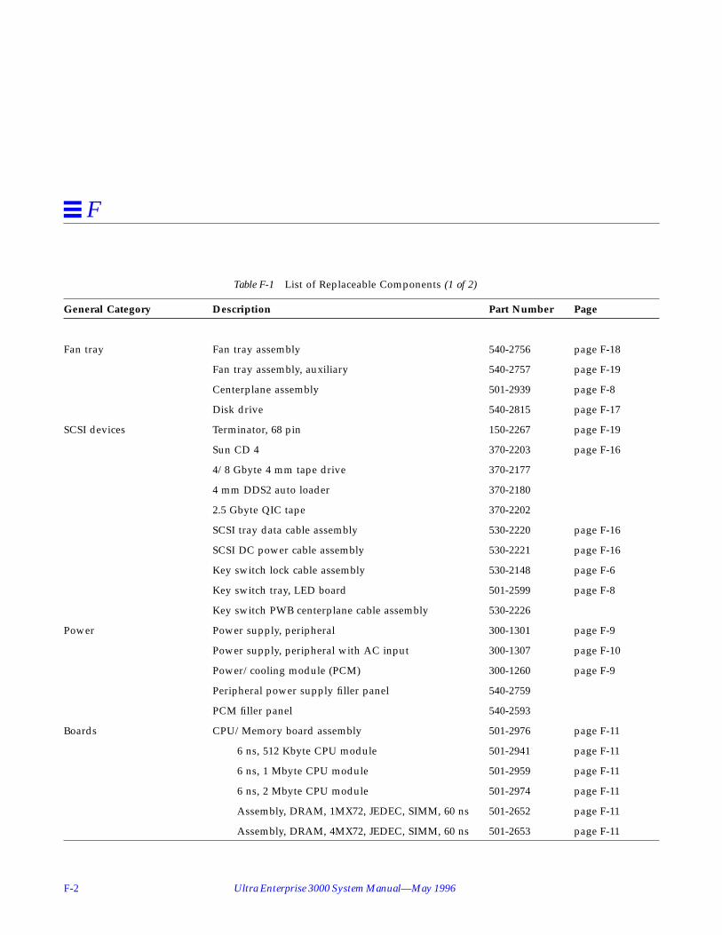
F-2 Ultra Enterprise 3000 System Manual—May 1996
F
Table F-1 List of Replaceable Components (1 of 2)
General Category Description Part Number Page
Fan tray Fan tray assembly 540-2756 page F-18
Fan tray assembly, auxiliary 540-2757 page F-19
Centerplane assembly 501-2939 page F-8
Disk drive 540-2815 page F-17
SCSI devices Terminator, 68 pin 150-2267 page F-19
Sun CD 4 370-2203 page F-16
4/8 Gbyte 4 mm tape drive 370-2177
4 mm DDS2 auto loader 370-2180
2.5 Gbyte QIC tape 370-2202
SCSI tray data cable assembly 530-2220 page F-16
SCSI DC power cable assembly 530-2221 page F-16
Key switch lock cable assembly 530-2148 page F-6
Key switch tray, LED board 501-2599 page F-8
Key switch PWB centerplane cable assembly 530-2226
Power Power supply, peripheral 300-1301 page F-9
Power supply, peripheral with AC input 300-1307 page F-10
Power/cooling module (PCM) 300-1260 page F-9
Peripheral power supply filler panel 540-2759
PCM filler panel 540-2593
Boards CPU/Memory board assembly 501-2976 page F-11
6 ns, 512 Kbyte CPU module 501-2941 page F-11
6 ns, 1 Mbyte CPU module 501-2959 page F-11
6 ns, 2 Mbyte CPU module 501-2974 page F-11
Assembly, DRAM, 1MX72, JEDEC, SIMM, 60 ns 501-2652 page F-11
Assembly, DRAM, 4MX72, JEDEC, SIMM, 60 ns 501-2653 page F-11

Illustrated Parts Breakdown (IPB) F-3
F
Assembly, DRAM, 16MX72, JEDEC, SIMM, 60 ns 501-2654 page F-11
SBus I/O board assembly 501-2977 page F-12
Graphics I/O board assembly 501-2749 page F-13
Optical link card 370-1426
DFB, FFB Graphics Card, 67 MHz 501-4126
SFB, FFB Graphics Card, 67 MHz 501-4127
Clock board assembly 501-2975 page F-14
Board, filler panel 540-2592 page F-15
Table F-1 List of Replaceable Components (2 of 2)
General Category Description Part Number Page

F-4 Ultra Enterprise 3000 System Manual—May 1996
F
Table F-2 Front View
Key Description Part Number
1 Disk drive 540-2815
2 Sun CD 4 370-2203
3 LED board 501-2599
4 Key switch lock cable 530-2148
5 Fan tray assembly 540-2756
2
3
1
4
5

Illustrated Parts Breakdown (IPB) F-5
F
Table F-3 Rear View
Key Description Part Number
6 Auxiliary fan tray 540-2757
7 PCM 300-1260
8 Power supply, peripheral/AC input 300-1307
9 Power supply, peripheral 300-1301
10 Clock board assembly 501-2975
11 SBus I/O board assembly 501-2977
12 CPU/Memory board assembly 501-2976
6
8
11
7
10
9
12
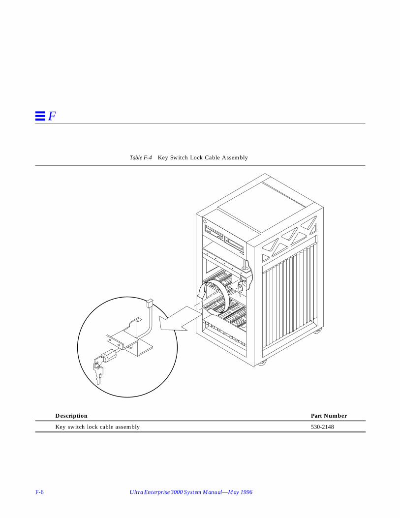
F-6 Ultra Enterprise 3000 System Manual—May 1996
F
Table F-4 Key Switch Lock Cable Assembly
Description Part Number
Key switch lock cable assembly 530-2148
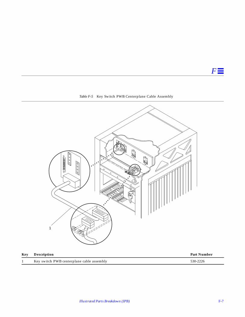
Illustrated Parts Breakdown (IPB) F-7
F
Table F-5 Key Switch PWB Centerplane Cable Assembly
Key Description Part Number
1 Key switch PWB centerplane cable assembly 530-2226
1

F-8 Ultra Enterprise 3000 System Manual—May 1996
F
Table F-6 Key Switch Tray, LED Board
Description Part Number
LED board 501-2599
Table F-7 Centerplane Assembly
Description Part Number
Centerplane assembly 501-2939
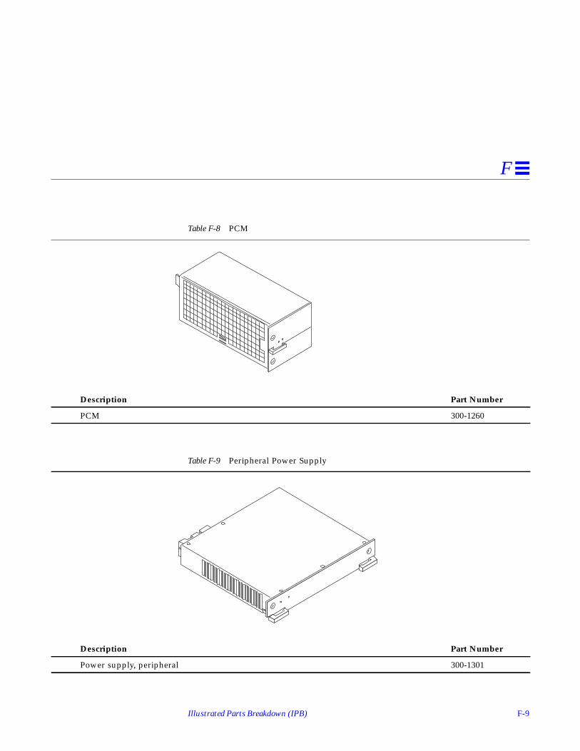
Illustrated Parts Breakdown (IPB) F-9
F
Table F-8 PCM
Description Part Number
PCM 300-1260
Table F-9 Peripheral Power Supply
Description Part Number
Power supply, peripheral 300-1301

F-10 Ultra Enterprise 3000 System Manual—May 1996
F
Table F-10 Peripheral Power Supply/AC Input
Description Part Number
Power supply, peripheral with AC input 300-1307

Illustrated Parts Breakdown (IPB) F-11
F
Table F-11 CPU/Memory Board Assembly
Description Part Number
CPU/Memory board assembly 501-2976

F-12 Ultra Enterprise 3000 System Manual—May 1996
F
Table F-12 SBus I/O Board Assembly
Description Part Number
SBus I/O board assembly 501-2977

Illustrated Parts Breakdown (IPB) F-13
F
Table F-13 Graphics I/O Board Assembly
Description Part Number
Graphics I/O board assembly 501-2749

F-14 Ultra Enterprise 3000 System Manual—May 1996
F
Table F-14 Clock Board Assembly
Description Part Number
Clock board assembly 501-2975

Illustrated Parts Breakdown (IPB) F-15
F
Table F-15 Filler Board Panel Assembly
Description Part Number
Filler panel board assembly 540-2592

F-16 Ultra Enterprise 3000 System Manual—May 1996
F
Table F-16 SCSI Tray Assembly
Key Description Part Number
1 Tape drive
2 Sun CD 4 370-2203
3 SCSI tray data cable assembly 530-2220
4 SCSI DC power cable assembly 530-2221
12
4
3

Illustrated Parts Breakdown (IPB) F-17
F
Table F-17 Disk Drive
Description Part Number
Disk drive 540-2815
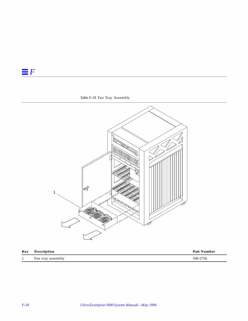
F-18 Ultra Enterprise 3000 System Manual—May 1996
F
Table F-18 Fan Tray Assembly
Key Description Part Number
1 Fan tray assembly 540-2756
1
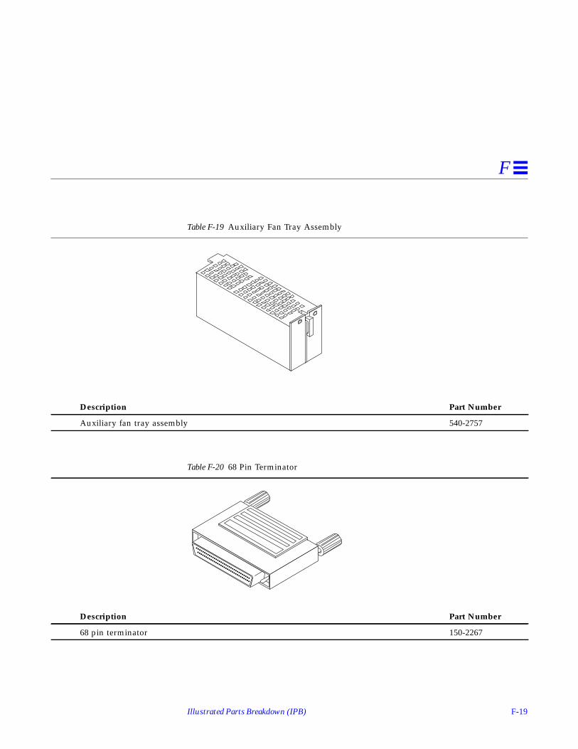
Illustrated Parts Breakdown (IPB) F-19
F
Table F-19 Auxiliary Fan Tray Assembly
Description Part Number
Auxiliary fan tray assembly 540-2757
Table F-20 68 Pin Terminator
Description Part Number
68 pin terminator 150-2267

F-20 Ultra Enterprise 3000 System Manual—May 1996
F

G-1
Connectors G
G.1 CPU/Memory BoardFigure G-1 shows the locations of the centerplane and CPU module connectors.
CPU/Memory Board page G-1
I/O Boards page G-5
Clock Board page G-11

G-2 Ultra Enterprise 3000 System Manual—May 1996
G
Figure G-1 CPU/Memory Board Connector Locations
G.1.1 Centerplane Connector
Note – Information for the CPU/Memory board centerplane connector alsoapplies to the I/O board centerplane connector.
The CPU/Memory board centerplane connector is mounted on the rear of theboard, opposite the side of the board with the LED display and extractionlevers. See Figure G-2. The connector is comprised of modular sections, eachwith its own set of receptacle pins. See Figure G-3.
288 pin connector
Centerplaneconnector
144 pinconnector
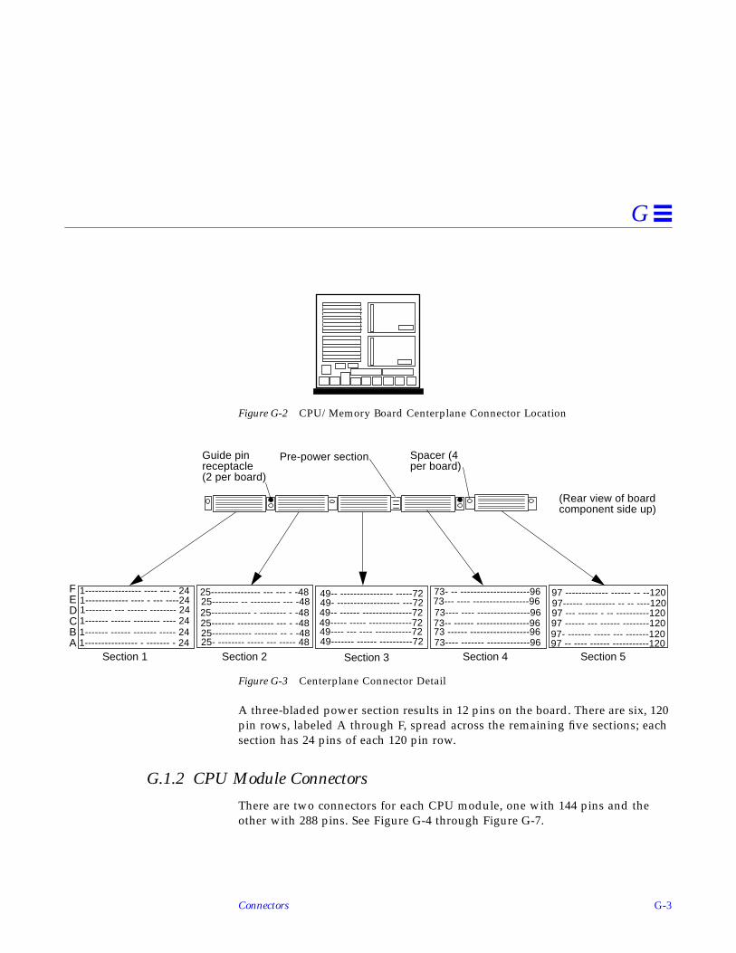
Connectors G-3
G
Figure G-2 CPU/Memory Board Centerplane Connector Location
Figure G-3 Centerplane Connector Detail
A three-bladed power section results in 12 pins on the board. There are six, 120pin rows, labeled A through F, spread across the remaining five sections; eachsection has 24 pins of each 120 pin row.
G.1.2 CPU Module Connectors
There are two connectors for each CPU module, one with 144 pins and theother with 288 pins. See Figure G-4 through Figure G-7.
(Rear view of board
1----------------- ---- --- - 24 49-- ---------------- -----72 73- -- ---------------------96 97 ------------- ------ -- --120FEDCBA
Guide pinreceptacle(2 per board)
Spacer (4per board)
Pre-power section
1------------- ---- - --- ----241-------- --- ------ -------- 24
1---------------- - ------- - 241------- ------ ------- ----- 241------- ------ -------- ---- 24
25--------------- --- --- - -48
25- -------- ----- --- ----- 48 49------- ------ ----------72 73---- ------- -------------96 97 -- ---- ------ -----------12097- ------- ----- --- -------120
97------ --------- -- -- ----120
97 ------ --- ------ --------12097 --- ------ - -- ----------120
73--- ---- -----------------9673---- ---- ----------------9673-- ------ ----------------9673 ------ ------------------96
49- ------------------- ---72
49----- ----- -------------7249-- ------ ---------------72
49---- --- ---- -----------72
25-------- -- --------- --- -4825------------ - -------- - -4825------- ----------- --- - -4825------------ ------- -- - -48
Section 1 Section 2 Section 3 Section 4 Section 5
component side up)

G-4 Ultra Enterprise 3000 System Manual—May 1996
G
Figure G-4 CPU Module 0 Connector (144 Pin) Location
Figure G-5 CPU Module 1 Connector (144 Pin) Location
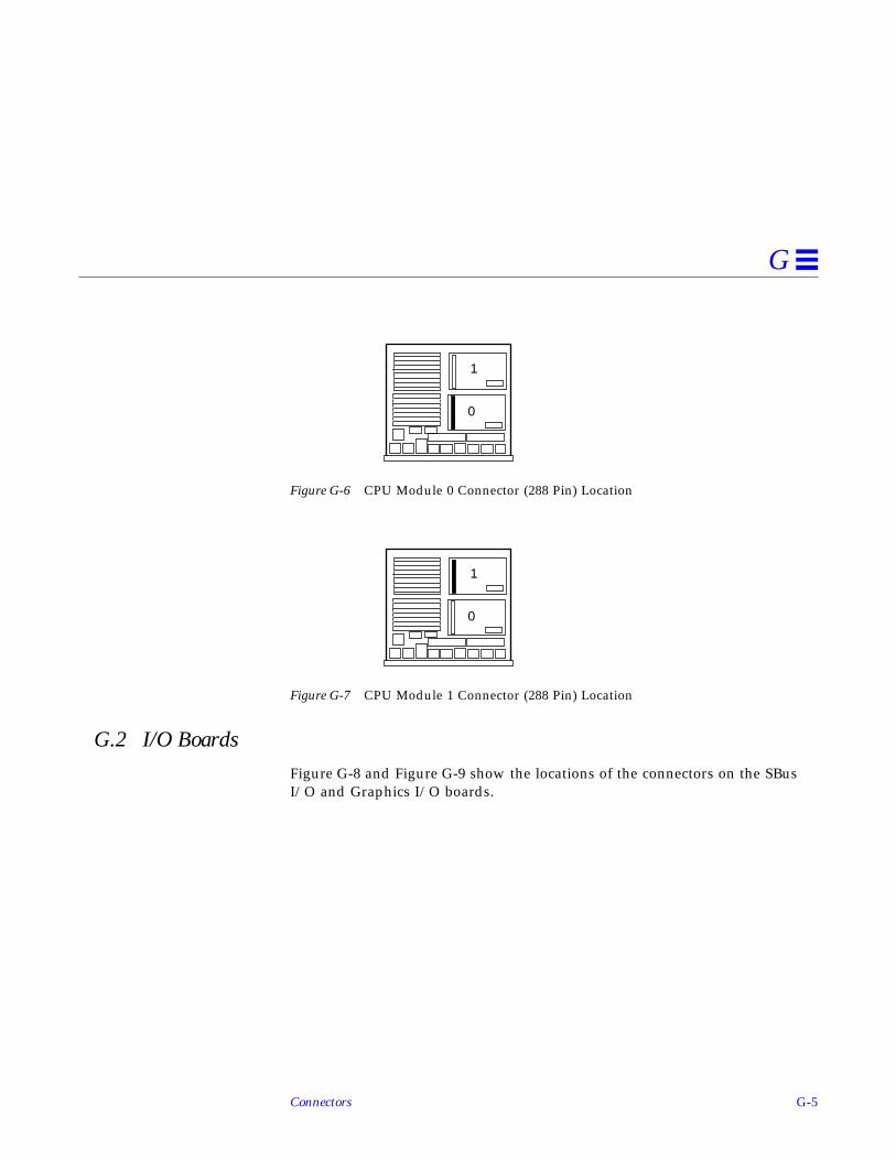
Connectors G-5
G
Figure G-6 CPU Module 0 Connector (288 Pin) Location
Figure G-7 CPU Module 1 Connector (288 Pin) Location
G.2 I/O BoardsFigure G-8 and Figure G-9 show the locations of the connectors on the SBusI/O and Graphics I/O boards.
0
1
0
1
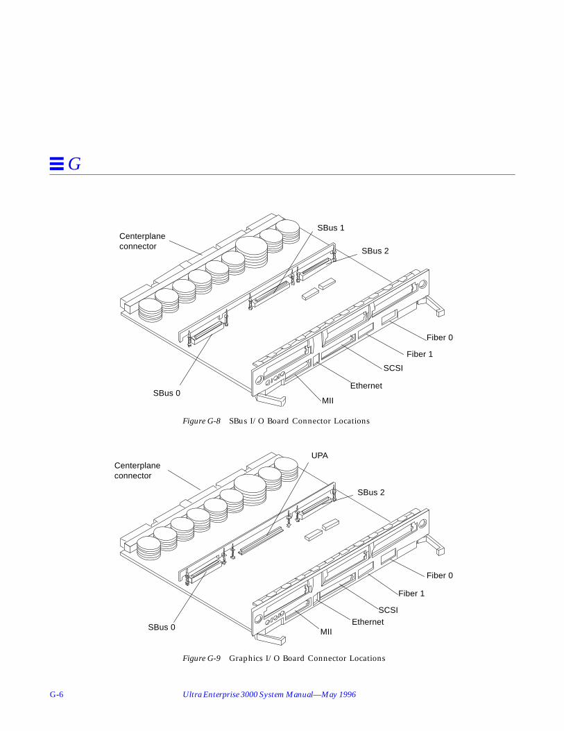
G-6 Ultra Enterprise 3000 System Manual—May 1996
G
Figure G-8 SBus I/O Board Connector Locations
Figure G-9 Graphics I/O Board Connector Locations
SBus 0
SBus 1
SBus 2
MII
Centerplaneconnector
Ethernet
SCSI
Fiber 1
Fiber 0
SBus 0
UPA
SBus 2
Centerplaneconnector
Fiber 0
Fiber 1
SCSIEthernet
MII
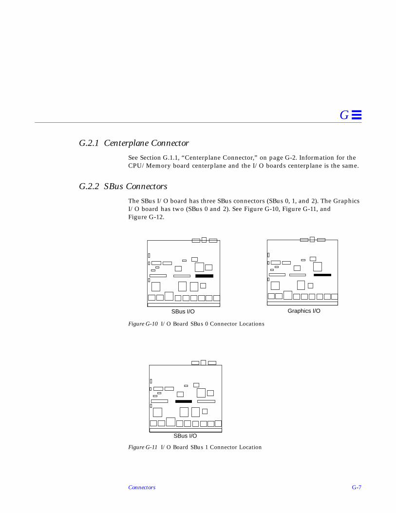
Connectors G-7
G
G.2.1 Centerplane Connector
See Section G.1.1, “Centerplane Connector,” on page G-2. Information for theCPU/Memory board centerplane and the I/O boards centerplane is the same.
G.2.2 SBus Connectors
The SBus I/O board has three SBus connectors (SBus 0, 1, and 2). The GraphicsI/O board has two (SBus 0 and 2). See Figure G-10, Figure G-11, andFigure G-12.
Figure G-10 I/O Board SBus 0 Connector Locations
Figure G-11 I/O Board SBus 1 Connector Location
SBus I/O Graphics I/O
SBus I/O

G-8 Ultra Enterprise 3000 System Manual—May 1996
G
Figure G-12 I/O Board SBus 2 Connector Locations
G.2.3 UPA Connector Location
The Graphics I/O board has one UPA connector.
Figure G-13 Graphics I/O Board UPA Connector Location
SBus I/O Graphics I/O
Graphics I/O

Connectors G-9
G
G.2.4 Ethernet Connector (TPE)
Figure G-14 I/O Board Ethernet Connector Locations
G.2.5 MII Connector
Figure G-15 I/O Board MII Connector Locations
Graphics I/OSBus I/O
Graphics I/OSBus I/O

G-10 Ultra Enterprise 3000 System Manual—May 1996
G
G.2.6 Fiber Interface Connectors
Figure G-16 I/O Board Fiber 0 Interface Connector Locations
Figure G-17 I/O Board Fiber 1 Interface Connector Locations
Graphics I/OSBus I/O
Graphics I/OSBus I/O

Connectors G-11
G
G.2.6.1 SCSI Connector
Figure G-18 I/O Board SCSI Connector Locations
G.3 Clock BoardFigure G-19 shows the clock board connector locations.
Figure G-19 Clock Board Connector Locations
Graphics I/OSBus I/O
Centerplane connector
Serial port B
Keyboard/mouse
Serial port ANot used
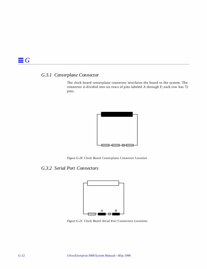
G-12 Ultra Enterprise 3000 System Manual—May 1996
G
G.3.1 Centerplane Connector
The clock board centerplane connector interfaces the board to the system. Theconnector is divided into six rows of pins labeled A through F; each row has 72pins.
Figure G-20 Clock Board Centerplane Connector Location
G.3.2 Serial Port Connectors
Figure G-21 Clock Board Serial Port Connectors Locations
A B

Connectors G-13
G
Figure G-22 Serial Port A and B Connector Pinouts
G.3.3 Keyboard and Mouse Connector
Figure G-23 Clock Board Keyboard/Mouse Connector Location
1 132514
1 132514
12 TXDA3 RXDA4 RTSA5 CTSA6 DSRA7 GND8 DCDA910111213
14DBA 15
16DDA 17
1819
DTRA 20212223
DAA 2425
12 TXDB3 RXDB4 RTSB5 CTSB6 DSRB7 GND8 DCDB910111213
14DBB 15
16DDB 17
1819
DTRB 20212223
DAB 2425
Serial port connector A
End view
Serial port connector B

G-14 Ultra Enterprise 3000 System Manual—May 1996
G
Figure G-24 Keyboard and Mouse Connector Pinouts
8 7 6
5 4 3
2 1

Index-1
Index
AAC power
switch, 11-3access, internal, 12-2assembly drawing See illustrated parts
breakdownauxiliary fan tray
remove, E-3 to E-5replace, E-5
Bbezel
frontremove, E-6 to E-7replace, E-23
boardclock, 5-1, B-10configuration in card cage, D-1CPU/Memory, 3-1, B-4filler panel, 3-2I/O, 4-1, B-6
FFB, B-8install, 4-13releasing, 4-11removing, 4-10types, B-2
boot message, 11-6
Ccabinet, expansion, B-12cable assembly
CD tray dataremove, E-10replace, E-10
CD tray powerremove, E-10replace, E-10
configuration, D-5external, 11-3
cardfibre, 4-27graphics (UPA), 4-23retainer, SBus, 4-20, 4-26
card cageconfiguration, 8-7, D-1
CD-ROM, 7-2SCSI target ID number, C-1tray, B-12, D-6
centerplaneremove, E-18 to E-20replace, E-20 to E-22
clock board, B-10description, 5-1LED codes, 8-4
configurationboards

Index-2 Ultra Enterprise 3000 System Manual—May 1996
CPU/Memory, D-3filler, D-3I/O, D-2
card cage, 8-7, D-1Ethernet, D-5memory modules, D-4power supplies, D-3rules for system, D-1 to D-5SBus cards, D-4SCSI, D-5UltraSPARC modules, D-4
cooling and power issuesCPU/Memory board, 3-9
CPU/Memory board, B-4components, 3-1configuration, D-3hot-plug, 3-3LED codes, 8-4module descriptions, D-4
Ddescription
boardsCPU/Memory, 3-1I/O, 4-4
functional, B-1OpenBoot, 8-10POST, 8-10power supplies, 6-1
disable Link Integrity Test, 4-21disk drive, 7-5, B-11
caution, 11-5tray
configuration, D-6drawing, assembly See illustrated parts
breakdowndrive
disk, 7-5, B-11tape and CD-ROM, 7-1test manually, 11-5
DSBE/S cardpreparing, 4-20
DWIS/S cardpreparing, 4-20
Eelectrical specification, A-2enable Link Integrity Test, 4-21environmental requirements, A-3Ethernet, configuration, D-5expansion cabinet, B-12external cables, 11-3
Ffan tray
auxiliaryremove, E-3 to E-5replace, E-5
remove, E-2 to E-3replace, E-3
FFB I/O board, B-8fibre card, 4-27filler panel, 3-2, 4-2
configuration, D-3SBus card, 4-22, 4-26
front bezelremove, E-6 to E-7replace, E-23
front decorative panelLED codes (table), 8-4remove, E-8 to E-10replace, E-22, E-23
functional description, B-1
Ggraphics (UPA) card, 4-23
Hhalting the system, 5-6hot-plug
CPU/Memory board, 3-3I/O board, 4-4procedures, B-3servicing components, 12-1

Index-3
II/O board, 4-1, B-6
configuration, D-2cooling and power, 4-13description, 4-4handling, 4-2hot-plug, 4-4installation, 4-13SBus version, B-7slot selection, 4-13termination, 4-3
illustrated parts breakdown, table, F-2 toF-3
installationI/O board, 4-13SBus card, 4-19
interface, network, B-11internal
access, 12-2options, 1-3
Kkey switch
lock assemblyremove, E-14 to E-15replace, E-16
PWB centerplane assemblyremove, E-11 to E-13replace, E-13 to E-14
LLED
boardremove, E-17replace, E-17 to E-18
clock board, 8-4CPU/Memory board, 8-4disk tray, 8-7indicators, 8-3power supplies, 8-6
link integrity testdescription of, 4-5enabling and disabling, 4-21
loss of carrier message, 4-21
Mmaster, system, B-5memory module, 3-15, B-5
configuration, D-4message
boot, 11-6not responding, 4-21
modulememory, SIMM, B-5, D-4power/cooling (PDM), B-8UltraSPARC, 3-10, B-4
configuration, D-4
Nnetwork interface, B-11not responding message, 4-21
OOpenBoot, description, 8-10options, internal, 1-3overview
system, 1-1troubleshooting, 8-1
Ppanel
front decorativeremove, E-8 to E-10replace, E-22, E-23
sideremove, E-6 to E-7replace, E-23
parts, illustrated See illustrated partsbreakdown
PCM. See power/cooling moduleperipheral power supply, B-9
description, 6-3LEDs, 8-6replace, 6-5 to 6-7

Index-4 Ultra Enterprise 3000 System Manual—May 1996
physical specification, A-1POST
description, 8-10LEDs
front panel, 11-5restart, 11-5
poweroff, system, 11-1on, system, 11-4
power supplyconfiguration, D-3description, 6-1LED codes, 8-6PCM
description, 6-8 to 6-9, B-8LED codes (table), 8-6replace, 6-10 to 6-13troubleshooting, 6-9
peripheral, B-9description, 6-3LEDs, 8-6replace, 6-5 to 6-7
power/cooling moduledescription, 6-8 to 6-9LED codes (table), 8-6replace, 6-10 to 6-13troubleshooting, 6-9
precautionssafety, 2-1system, 10-4
preparingDSBE/S card, 4-20DWIS/S card, 4-20for service, 12-1new SBus card, 4-19
probe-scsi command, 8-11prtdiag command, 8-9
Rreleasing the board, 4-11, 4-12, 5-6remove
board, 4-10SBus card, 4-17
filler panel, 4-22, 4-26SCSI tray, 12-3TOD NVRAM, 5-7
replaceI/O board, 4-13
resetswitch, initiate POST, 8-2, 11-5
restartPOST, 11-5system, 11-4
Ssafety precautions, 2-1, 10-1SBus card
configuration, D-4filler panel, 4-22, 4-26installation, 4-19preparation, 4-19remove, 4-17retainer, 4-20, 4-26SBus I/O board, B-7test manually, 11-5
SCSIcable configuration, C-3, D-5devices, 7-1termination, C-3
I/O board, 4-3tray
remove, 12-3, E-8 to E-10replace, E-22target ID numbers, C-1
setup, terminal, 8-1shut down, system, 11-1side panel
remove, E-6 to E-7replace, E-23
SIMMs, 3-15, B-5configuration, D-4maximizing performance, 3-19
Solstice SyMON, 8-11specification
electrical, A-2environment, A-3

Index-5
physical, A-1standoff
lock and unlock, 4-17using, 4-17
SunVTS on-line validation test suite, 8-9switch
AC, 11-3reset, initiate POST, 8-2, 11-5
symbols, definitions, 10-2system
master, B-5overview, 1-1precautions, 10-4
Ttape drive, 7-2
SCSI target ID number, C-1tray, B-12, D-6
terminal settings, 8-1termination
I/O board, 4-3SCSI cable, C-3
testingdrive
SBus card, 11-5TOD NVRAN
remove, 5-7tools, 2-4, 10-5tray
CD-ROM/tape drive, B-12, D-6disk drive
configuration, D-6LEDs, 8-7
troubleshooting, 8-8flow diagrams, 9-1 to 9-8overview, 8-1power supply
power/cooling module, 6-9turning system
off, 11-1on, 11-4
UUltraSPARC module, B-4
configuration, D-4CPU/Memory board, 3-10
UPA (graphics) card, 4-23using standoffs, 4-17
Vvideo, configuration, D-5

Index-6 Ultra Enterprise 3000 System Manual—May 1996