ultimate energy saving - compressed air international · this enables the refrigerant system to...
TRANSCRIPT

Ultimate energy saving technology

CWt Chiller series
Partial load energy saving design
When the CWT chiller is operating at partial load with only some of the compressors running the efficiency increases because the heat exchangers are now oversized. In effect the CWT chillers with multiple compressors in the same circuit can achieve much better efficiency levels compared with competitive chillers with just one compressor per circuit. The diagram illustrates the CWT multiple compressor design energy saving bennefits.
Multi-CoMPressor Configuration
It is common practice to size chillers for the maximum output required. During normal operating conditions throughout the day and year the maximum output of the chiller is rarely required and for only short periods of time. The CWT chillers use a multiple compressor configuration from model CWT030 and up. This enables the refrigerant system to adapt to the true output required instantaneously. This design results in significant reduction in electrical consumption, a higher efficiency during partial loads because of the over-sized heat exchangers, lower start up current in-rush and an increase in the average life of the compressors. The multi-compressor configuration guarantees higher seasonal energy efficiency verses using a large single compressor unit which would require more energy even in low load periods.
Cwt PurestreaM series water ChillersThe new CWT Purestream chiller range is specifically designed to meet the stringent cooling requirements of today’s advanced equipment and processes. The CWT range proivides precise temperature control of chilled water temperature while operating over long periods of time with varying load demands for many industries and applications. The range includes 14 models providing capacities from 2.4 tons to 36.5 tons and designed to be installed indoors or outdoors. The Purestream CWT chillers are equipped with the necessary components to provide reliable effective cooling and energy saving operation. All units are equipped with: • finned aluminium micro-channel condenser • rotaryorscrollhermeticcompressors• environmentallyfriendlyrefrigerantgasR410a• brazedplateevaporator• electricfanswithcontinualspeedcontrol• microprocessorcontroller• ventilatedcontrolpanel• thermallyinsulatedwaterstoragetank• hydraulicpump• stainlesssteelcondenserfilters• waterfilterandshut-offvalves
Multi-Channel aluMinuM Condensers
The new Micro-channel aluminium plate condensers guarantee a larger surface area providing enhanced heat exchange when compared to the traditional copper tube condensers. The result is a reduction in the refrigerant charge estimated from 30% to 35% less than the traditional condenser design. The all aluminium condensers are treated which makes them resistant to any galvanic reaction and corrosion. To protect the condensers all CWT chillers include stainless steel mesh condenser filters that are easlily removed for service and cleaning.

r410a refrigerant
Due to its thermal dynamic performance, the R410A refrigerant gas allows the refrigeration system to operate at high efficiency. The higher operating pressure of the R410A refrigerant has allowed for the development of a more compact design chiller range.
evaPorator
The stainless steel brazed plate evaporator is compact in size, extremely efficient and installed independent of the storage tank. The electronic control anti-freeze function keeps the evaporator’s outlet water temperature under control in order to prevent the evaporator from freezing up. A differential pressure switch protects the evaporator against no or low water flow. A mechanical inlet water filter (standard) protects the entire hydraulic circuit against any contamination coming from the system. The models CWT075 to CWT130 are designed with a double refrigerant circuit and single water circuit. This configuration is very efficient with partial loads, compared to independent evaporator solutions.
refrigerant CirCuit
The refrigerant circuit is produced by specialized personnal utilizing high quality materials and rigorous brazing procedures that conform to directive 97/23. The refrigerent circuit consists of: AISI 316 stainless steel brazed plate exchanger, micro-channel aluminium condensers, rotary compressors (models CWT007 and CWT010) and scroll compressors designed for R410A refrigerant, dehydration filter, sight glass humidity indicator, thermostatic expansion valve with external equalisation, reverse flow check valves for models with mutli compressors, manual reset high pressure switch and automatic reset low pressure switch, high and low pressure gauges and refrigerant maintanence connection points.
hydrauliC CirCuit
Composed of a thermally insulated storage tank made of carbon steel c/w: expansion tank, shut-off ball valves, by-pass valve, safety valve, automatic venting valve, differential pressure switch, level sensor, water filter, drain valve, pressure gauge and multi-stage centrifugal electric pump with high efficiency impeller. The high liquid volume to compressor cooling capacity ratio maintains a constant outlet water temperature while minimizing compressor starts and stops. Where the multi-compressor configuration is used the storage tank is smaller which allows for a faster start up to reach plant cooling water requirements. The water storage tank is postioned on the water outlet in order to limit temperature fluctuations due to the compressors being switched on and off. Within the unit there is also a small by-pass tube between the water inlet and outlet designed to prevent problems caused by water valves being closed unintentionally.
rotary and sCroll CoMPressor
CWT chillers utilize rotary and scroll compressors as a standard. These compressors are the best available technology today for the cooling requirments of the CWT chillers. They are known for their reliability and efficiency through their widespread use in the air conditioning and refrigeration industies. The scroll compressor has the additional benefits of quiet operation, no vibration and the ability to adsorb liquid returns. Compressors are mounted on rubber anti-vibration pads designed to reduce noise and the effects of vibration. They are also protected by an electronic device that monitors the phase sequence in order to avoid reverse rotation. Compressors are all equipped with a crankcase heater as standard.

fraMe and CaBinet
All frame and cabinetry material are made from galvanized steel and painted in a powder coat paint finish. This allows for indoor and outdoor installation and provides protection in harsh environments. All fasteners are either stainless steel or electro- galvanized materials. The CWT cabinet was designed so that all parts, particularly those requiring maintenance and cleaning are easy to access without interfering with the chiller operation. The chiller cabinet is accessible on three sides allowing for easy maintenance and also designed with safety to the operator in mind.
fans
The 4/6/8 pole axial fan motors are complete with an external rotor blade which is activated by condensing pressure measured by a pressure transducer. This leads to more regular operation and lower usage which extends the lifespan of the fan motor. All fans have a protection grill, thermally heat protected with automatic reset and class F insulation.
Control Panel The control panel complys with the Canadian electrical code and includes door lock disconnect which prevents access to the control panel when it is powered. The watertight door provides easy access to the electronic controller as well as the numbered panel wires provide easy trouble shooting and maintenance. Each control panel includes: thermo-magnetic motor protectors for the compressors and pump, contactors, autotransformers, compressor rotation direction control devices, ON/OFF switch on the panel door. The control panel also includes an active ventilation system to prevent over heating when the unit is in operation.
hydrauliC CirCuit CirCulation PuMPs
All units are equipped with a high efficiency multi-stage centrifugal pump with steel impeller. All parts coming in contact with fluid are AISI 304 stainless steel. The mechanical seals are carbon/ceramic/EPDM as standard therefore making it possible to use water and ethylene glycol mixtures of up to 30%. The pump motor is 2-pole, self-ventilated, with class F insulation and IP55 protection level. The entire CWT series chillers utilize P3 pump pressure as standard and optional P5 pressure. Double pump option is also avaiable upon request.
CWt Chiller series
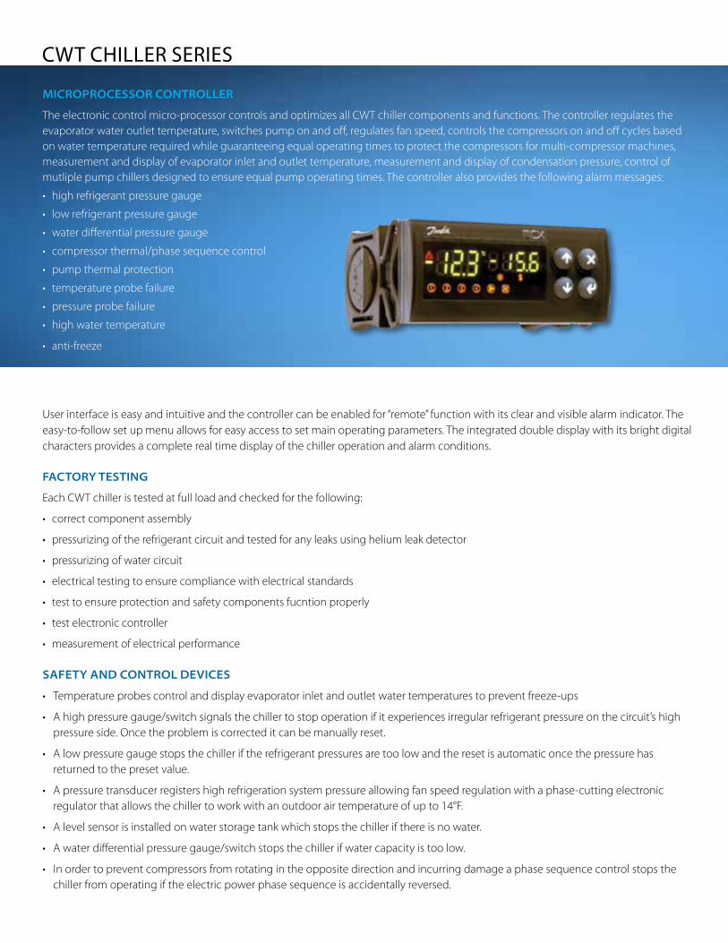
User interface is easy and intuitive and the controller can be enabled for “remote” function with its clear and visible alarm indicator. The easy-to-follow set up menu allows for easy access to set main operating parameters. The integrated double display with its bright digital characters provides a complete real time display of the chiller operation and alarm conditions.
faCtory testing
Each CWT chiller is tested at full load and checked for the following:
• correctcomponentassembly
• pressurizingoftherefrigerantcircuitandtestedforanyleaksusingheliumleakdetector
• pressurizingofwatercircuit
• electricaltestingtoensurecompliancewithelectricalstandards
• testtoensureprotectionandsafetycomponentsfucntionproperly
• testelectroniccontroller
• measurementofelectricalperformance safety and Control deviCes
• Temperatureprobescontrolanddisplayevaporatorinletandoutletwatertemperaturestopreventfreeze-ups
• Ahighpressuregauge/switchsignalsthechillertostopoperationifitexperiencesirregularrefrigerantpressureonthecircuit’shigh pressure side. Once the problem is corrected it can be manually reset.
• Alowpressuregaugestopsthechilleriftherefrigerantpressuresaretoolowandtheresetisautomaticoncethepressurehas returned to the preset value.
• Apressuretransducerregistershighrefrigerationsystempressureallowingfanspeedregulationwithaphase-cuttingelectronic regulator that allows the chiller to work with an outdoor air temperature of up to 14°F.
• Alevelsensorisinstalledonwaterstoragetankwhichstopsthechillerifthereisnowater.
• Awaterdifferentialpressuregauge/switchstopsthechillerifwatercapacityistoolow.
• Inordertopreventcompressorsfromrotatingintheoppositedirectionandincurringdamageaphasesequencecontrolstopsthe chiller from operating if the electric power phase sequence is accidentally reversed.
MiCroProCessor Controller
The electronic control micro-processor controls and optimizes all CWT chiller components and functions. The controller regulates the evaporator water outlet temperature, switches pump on and off, regulates fan speed, controls the compressors on and off cycles based on water temperature required while guaranteeing equal operating times to protect the compressors for multi-compressor machines, measurement and display of evaporator inlet and outlet temperature, measurement and display of condensation pressure, control of mutliple pump chillers designed to ensure equal pump operating times. The controller also provides the following alarm messages:
• highrefrigerantpressuregauge
• lowrefrigerantpressuregauge
• waterdifferentialpressuregauge
• compressorthermal/phasesequencecontrol
• pumpthermalprotection
• temperatureprobefailure
• pressureprobefailure
• highwatertemperature
• anti-freeze

oPtional CoMPonents
CWT Model 010-030 038-090 110-130
P5 Pump O O O
Double P3 pump 6 O O
Double P5 pump 6 O 6
Version without tank O O O
Version without pump O O O
Open hydraulic circuit with additional loading tank O O O
Non ferrous material version O O O
Automatic filling kit O O O
Remote control panel O O O
Wheels O O O
Feet/Legs O O O
Legend: 6 not available; l as standard; O optional
aPPliCations
•Plastics(injection,blowmolding,extrusion,filmextrusion,thermoforming)
•PrintingandGraphics(manufacture,printing,cardboard,labels,plasticfilm)
•Medicalimaging
•Food(beverage,confectionery,chocolate,processing,storage)
•Lasers(welding,profiling,cutting,optics,medical,marking,aesthetics)
•Mechanical(welding,cutting,profiling,polishing,rolling,grinding)
•Other(wood,ceramics,gold,biogaspharmaceutical,compressedair,textile)
• Hydrauliccircuitcooling,MachineTool
• PaintandFinishing
• EDM

CWT Unit 010 015 018 020 030 038 040
Cooling capacity (1) Tons 2.1 3.4 4.4 5.3 6.5 9 10.9
Cooling capacity (1) kW 7.4 11.9 15.4 18.7 22.8 31.5 38.4
Compressors power input (1) kW 1.8 3.2 3.6 5.0 6.7 7.1 10.0
Total power input (1) (2) kW 2.9 4.4 4.8 6.3 7.9 9.8 12.7
Total absorbed current (1) (2) A 5.30 7.44 9.56 11.72 13.80 18.45 22.75
EER (pump excluded) (1) -- 3.81 3.70 4.30 3.83 3.60 4.43 3.96
Water flow (1) gal/min 6.4 10.2 13.3 16.1 19.5 27.3 33.1
Available pressure (1) (2) psig 55.5 39.1 54.0 48.9 42.2 50.8 37.3
Maximum power input (total) (2) (3) kW 3.9 5.8 7.2 8.5 10.6 14.7 17.1
Maximum absorbed current (total) (2) (3) A 6.6 9.5 12.6 14.5 17.6 24.6 28.4
Starting current (2) (3) A 35.7 41.7 58.1 74.1 49.9 70.1 88.0
Fan power kW 0.40 0.40 0.50 0.50 0.50 0.50 0.50
Fan current A 1.80 1.80 4.60 4.60 4.60 4.60 4.60
Number of fans # 1 1 1 1 1 2 2
Pump power input (2) kW 0.74 0.74 0.74 0.74 0.74 1.70 1.70
Pump absorbed current (2) A 1.80 1.80 1.80 1.80 1.80 2.98 2.98
Refrigerant -- R410A
Power supply Voltage 460/3/60 (575/3/60 transformer supplied loose when required)
Compressor type -- Rotary Scroll
Evaporator type -- Brazed plates
Condenser type -- Microchannel
N° of compressors # 1 1 1 1 2 2 2
N° of refrigerant circuits # 1 1 1 1 1 1 1
Air flow cfm 2558 2667 4814 4814 4738 9063 9063
Sound pressure level (4) dB(A 43.0 43.0 50.0 50.0 50.0 53.0 53.0
Water connections diameter NPT " 1" 1" 1" 1" 1" 1 1/2" 1 1/2"
Tank capacity gal 25.1 25.1 25.1 25.1 25.1 35.7 35.7
Expansion vessel capacity gal 1.3 1.3 1.3 1.3 1.3 2.1 2.1
Maximum pressure in hydraulic circuit psig 87
IP protection degree -- IP44
Width inch 26.1 26.1 26.1 26.1 26.1 29.6 29.6
Depth inch 39.0 39.0 51.4 51.4 51.4 64.4 64.4
Height inch 52.6 52.6 56.1 56.1 56.1 60.4 60.4
Weight lb 474 573 584 606 717 882 904
P5 PUMP DATA
Pump power input kW 0.7 0.7 1.3 1.3 1.3 2.5 2.5
Pump absorbed current A 1.8 1.8 2.5 2.5 2.5 4.3 4.3
Available pressure (1) (5) psig 85.8 61.6 85.4 77.8 67.0 81.2 64.9
(1) Data based on the following conditions: water temperature in/out: 59/50°F (15/10°C) - ambient air temperature: 77°F (25°C)
(2) Data based on unit with standard P3 pump
(3) Data based on worst conditions allowed by safety devices fitted on the unit
(4) Based on 10 meter distance in an open environment
(5) Data based on unit with P5 pump (optional)
(6) For models from CWT010 to CWT065 with additional loading tank, length increases by 12 inches.

TECHNICAL DATACWT Unit 045 055 065 075 090 110 130
Cooling capacity (1) Tons 10.3 13.0 15.6 17.5 21.5 26.4 32.2
Cooling capacity (1) kW 36.1 45.8 54.8 61.5 75.5 92.7 113.1
Compressors power input (1) kW 9.4 11.4 16.1 14.0 19.6 20.7 30.8
Total power input (1) (2) kW 12.9 16.0 20.7 21.9 27.5 31.9 42.0
Total absorbed current (1) (2) A 22.67 26.28 33.18 34.06 42.47 49.99 65.04
EER (pump excluded) (1) -- 3.96 3.85 3.42 3.63 3.45 4.13 3.58
Water flow (1) gal/min 31.1 39.5 47.1 53.3 65.5 80.4 97.3
Available pressure (1) (2) psig 50.7 48.0 45.3 42.5 34.6 56.9 55.0
Maximum power input (total) (2) (3) kW 17.6 22.6 26.2 31.9 36.7 43.7 54.5
Maximum absorbed current (total) (2) (3) A 29.2 34.6 40.3 46.7 54.3 67.9 81.0
Starting current (2) (3) A 61.4 80.1 99.9 92.2 113.9 145.5 140.6
Fan power kW 0.50 1.05 1.05 2.70 2.70 2.50 2.50
Fan current A 4.60 4.80 4.80 4.20 4.20 4.20 4.20
Number of fans # 2 2 2 2 2 2 2
Pump power input (2) kW 2.50 2.50 2.50 2.50 2.50 6.20 6.20
Pump absorbed current (2) A 4.30 4.30 4.30 4.30 4.30 10.20 10.20
Refrigerant -- R410A
Power supply Voltage 460/3/60 (575/3/60 transformer supplied loose when required)
Compressor type -- Scroll
Evaporator type -- Brazed plates
Condenser type -- Microchannel
N° of compressors # 3 3 3 4 4 4 6
N° of refrigerant circuits # 1 1 1 2 2 2 2
Air flow cfm 9063 11060 11060 19382 19382 26006 26006
Sound pressure level (4) dB(A) 53.0 49.5 49.5 58.5 58.5 52.0 52.0
Water connections diameter NPT " 1 1/2" 1 1/2" 1 1/2" 2" 2" 2" 2"
Tank capacity gal 35.7 35.7 35.7 54.2 54.2 54.2 54.2
Expansion vessel capacity gal 2.1 2.1 2.1 3.2 3.2 3.2 3.2
Maximum pressure in hydraulic circuit psig 87
IP protection degree -- IP44
Width inch 32.8 32.8 32.8 43.7 43.7 47.6 47.6
Depth inch 72.8 72.8 72.8 79.7 79.7 87.8 87.8
Heigth inch 66.9 66.9 66.9 74.8 74.8 88.8 88.8
Weigth lb 1102 1102 1135 1587 1698 2161 2205
P5 PUMP DATA
Pump power input kW 4.0 4.0 4.0 4.0 4.0 on demand
Pump absorbed current A 7.5 7.5 7.5 7.5 7.5 on demand
Available pressure (1) (5) psig 80.6 75.8 71.3 67.1 57.1 on demand
(1) Data based on the following conditions: water temperature in/out: 59/50°F (15/10°C) - ambient airtemperature: 77°F (25°C)
(2) Data based on unit with standard P3 pump
(3) Data based on worst conditions allowed by safety devices fitted on the unit
(4) Based on 10 meter distance in an open environment
(5) Data based on unit with P5 pump (optional)
(6) For models from CWT010 to CWT065 with additional loading tank, length increases by 12 inches.

CorreCtion faCtors
Dimensional DataCWT010 – CWT015
CWT045 – CWT055 – CWT065
CWT110 – CWT130
CWT075 – CWT090
CWT018 – CWT020 – CWT030
CorreCtion faCtors – water flow CalCulation
Correction factor FΔT for cooling capacity with a water temperature difference other than 9°F (ΔT = Tw in - Tw out)
Correction factor FGly, for water flow for glycol concentration values different from 0%
With reference to water flow tables performance data, apply the correction factors for water flow values corresponding to a glycol percentage of 0%; other data is already calculated consistently with indicated glycol percentage value. Water flow calculation with a new water ΔT and new glycol percent is as follows:
Wf = (Cc x 23,97 x FGly)/ ΔT
LEGEND
Cc = Cooling capacity in Tons
Wf = Water flow in gal/min
FGly = Correction factor for glycol
ΔT = water temperature difference °F
ΔT °F 5 7 9 11 13 15 16 18
FΔT -- 0.98 0.99 1 1.12 1.27 1.33 1.37 1.04
Glycol % 0% 15% 20% 25% 30%
FGly 1.00 1.04 1.05 1.07 1.09
2871 Brighton Road, Oakville, Ontario, Canada L6H 6C9Tel: 905-829-9666 1-800-951-0777 fax: 905-829-8331Email: [email protected]