ulthariltration of munition was (imx, rbx … · ulthariltration of munition was (imx, rbx and tnt)...
TRANSCRIPT
lAD
TE~CL RENUT
NATICK/TE4VWS
ULThARILTRATION OF MUNITION WAS(IMX, RBX AND TNT)
LT I
lbI
UNS.,'--
Bit
AMoe fo pu , oes;dsruinulbtd
Ma.n ftae.mm nVsreotde o
cosiuea1flll1dotmto prvlo h
us ofsuhIta
61i7ti eotWo n ogrnee.D o
ro ttotec1gntr
SECURITY CLASSIFICATION OF THIS PAGE (When Data Entered)
REPORT DOCUMENTATION PAGE READ INSTRUCTIONSBEFORE COMPLETING FORM
I. REPORT NUMBER 2. GOVT ACCESSION NO. 3. RECIPIENT'S CATALOG NUMBER
Natick/TR-82/005 '4)// ,
4. TITLE (and Subtitle) S. TYPE OF REPORT & PERIOD COVERED
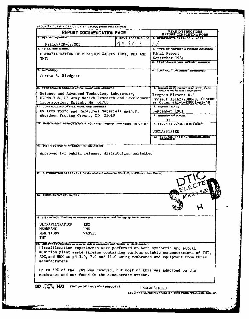
ULTRAFILTRATION OF MUNITION WASTES (HMX, RDX AND Final ReportTNT) September 1981
6. PERFORMING ORG. REPORT NUMBER
7. AUTHOR(*) 1. CONTRACT OR GRANT NUMBER(&)
Curtis R. Blodgett
9. PERFORMING ORGANIZATION NAME AND ADDRESS 10. PROGRAM ELEMENT, PROJECT, TASKAREA A WORK UNIT NUMBERS
Science and Advanced Technology Laboratory, Program Element 6.2DRDNA-YEB, US Army Natick Research and Development Pro ect Il62720DO48, Custom-Laboratories, Natick, MA 01760 er Order #Al-0-ROOO-A1-48
It. CONTROLLING OFFICE NAME AND ADDRESS 12. REPORT DATE
US Army Toxic and Hazardous Materials Agency, September 1981Aberdeen Proving Ground, MD 21010 13. NUMBER OF PAGES
3314. MONITORING AGENCY NAME & ADDRESSI! dilflermt from Controlling Office) IS. SECURITY CLASS. (of this report)
UNCLASS IFIED'So. DECL ASSI FICATION/ DOWNGRADING
SCHEDULE
IS. DISTRIBUTION STATEMENT (of thie Report)
Approved for public release, distribution unlimited
17. DISTRI13UTION STATEMENT (of the abstract entered In Block 20, if different from Report)
IS. SUPPLEMENTARY NOTES kfq ..
19. KEY WORDS (Continue on reveree elde if necoemy amd identify by block number)
ULTRAFILTRATION RDXMEMBRANE HMXMUNITIONS WASTESTNT
'M. ASTRAcT (cotawe ewe a N~ fneay end Identfy by block number)Ultrafiltration experiments were performed on both synthetic and actualmunition plant waste streams containing various soluble concentrations of TNT,RDX, and HMX at pH 3.0, 7.0 and 11.0 using membranes and equipment from threemanufacturers.
Up to 50% of the TNT was removed, but most of this was adsorbed on the*membranes and not found in the concentrate stream.
t J" 1473 [onOF! NOVSSiSoOLETE UNCLASSIFIEDSECURITY CLASSIFICATION OF THIS PAGE (fan, Dae Entered)
PREFACE
During the manufacture of certain munitions, suspended particles less
than 200 microns in size, as well as soluble quantities of TNT, RDX,and
HMX are found in waste streams. The use of multi-media filters prior to carbon
adsorption columns has proven ineffective due to plugging of the filters.
Because of recent developments and improvements in ultrafiltration
membranes, it was felt that this process might alleviate some of these problems.
This report describes the investigation of ultrafiltration as a means of
cleaning up munition plant waste streams. The customer order number for
this work was Al-O-RO0i-Al-48. 7
The analytical work was performed by John T. Walsh and Rosalinda
Bagalawis, while Richard Erickson helped immeasurably with running the
equipment and gathering data.
Accossion For
NTIS GRA&ITIC TAB 0
Uunanounced4Jutificatio
OsoBy
Distribution/.... A vilabil ty Cod s
Avntl and/or
/DiL>; c.
TABLE OF CONTENTS
Page
ILLUSTRATIVE DATA 4
INTRODUCTION
APPROACH 10
MATERIALS AND METHODS 11
DISCUSSION 14
CONCLUSIONS 25
LITERATURE CITED 26
APPENDIX A - Manufacturers of Membrane Equipment that Were Contacted 27
APPENDIX B - Literature Search Finds 30
APPENDIX C - Calculations 31
ANO
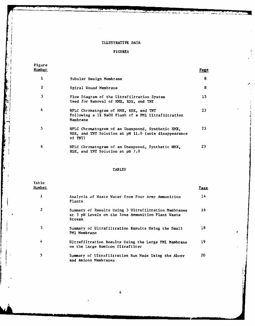
ILLUSTRATIVE DATA
FIGURES
Figure
Number Page
1 Tubular Design Membrane 8
2 Spiral Wound Membrane 8
i3 Flow Diagram of the Ultrafiltration System 15Used for Removal of HMX, RDX, and TNT
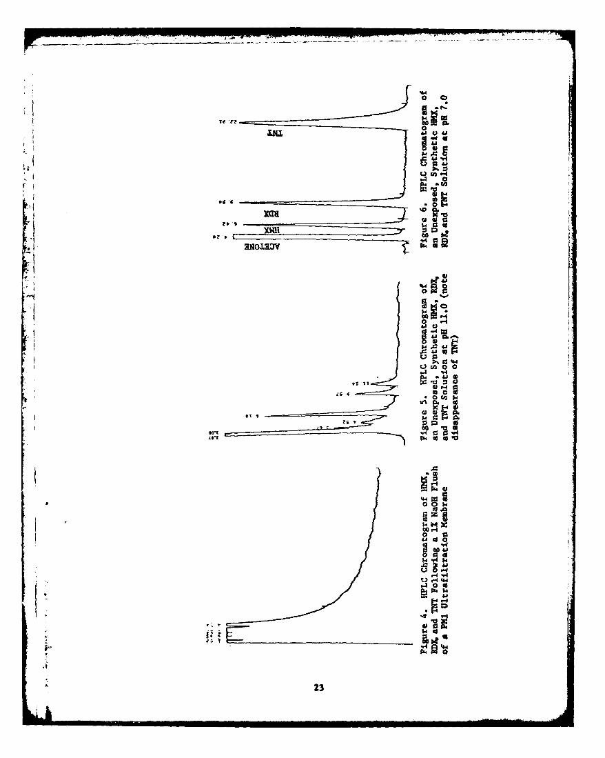
4 HPLC Chromatogram of HMX, RDX, and TNT 23Following a 1% NaOH Flush of a PM1 Ultrafiltration
Membrane
5 HPLC Chromatogram of an Unexposed, Synthetic HMX, 23
RDX, and TNT Solution at pH 11.0 (note disappearance
of TNT)
6 HPLC Chromatogram of an Unexposed, Synthetic HMX, 23
RDX, and TNT Solution at pH 7.0
TABLES
TableNumber
I Analysis of Waste Water from Four Army Ammunition 14
Plants
2 Summary of Results Using 3 Ultrafiltration Membranes 16
at 3 pH Levels on the Iowa Ammunition Plant WasteStream
3 Summary of Ultrafiltration Results Using the Small 18PMl Membrane
4 Ultrafiltration Results Using the Large PMI Membrane 19on the Large Romicon Ultrafilter
5 Summary of Ultrafiltration Run Made Using the Abcor 20
and Amicon Membranes
4

ULTRAFILTRATION OF MUNITION WASTES (HMX, RDX, and TNT)
INTRODUCTION
Waste streams - om certain Army ammunition plants contain suspended and
dissolved quantities of 2,4,6-trinitrotoluene (TNT), hexahydro-l,3,5-trinitro-
1,3,5-triazine (RDX), and oct.,'dro-,3,5,7-tetranitro-l,3,5,7-tetrazocine
(HMX). TNT in waste streams presents a particularly acute problem because
exposure to sunlight or alkali turns the water a deep rusty orange-like color.
While the color bodies have not been totally identified, it has been postulated
that azo-compounds, Meisenheimer complexes, and many other nitro-aromatic
compounds are formed as a result of the reactions of TNT.1' 2' 3
The purpose of this study was to explore ultrafiltration (UF) as a
technique for removing suspended and dissolved organic compounds from pink
water and to determine whether ultrafiltration can be used as a single
step process or in combination with other processes.
In ultrafiltration, water passes through a semi-permeable polymeric
membrane under a driving force of hydrostatic pressure, usually less than
7.0 kgf/cm2 (100 psig). The process fluid flows across the membrane which
has pore diameters in a range of 0.002 to 0.015 microns. Suspended solids
and the larger colloids are rejected at the membrane barrier while water
will permeate the membrane and emerge as ultrafiltrate. To best understand
1N. E. Burlinson, M. E. Sitzmann, D. J. Glover, and L. A. Kaplan. 1979.Photochemistry of TNT and Related Nitroaromatics: Part III. TechnicalReport NSWC/WOL TR 78-198, Naval Surface Weapons Center, Silver Spring, MD.
2R. K. Andren, J. M. Nystrom and R. J. Erickson. 1975. Treatment of TNTMunitions Wastewaters Using Polymeric Adsorption Resins. Food Sciences
Laboratory, US Army Natick Research and Development Command, Natick, MA.
3M. R. Crampton. 1973. Meisenheimer Complexes, Dept. of Chemistry, The
University of Durham, England. Technical paper.
5
where ultrafiltration can be used, it is important to understand where it fits
in with other filtration and separation processes.
The process of reverse osmosis utilizes membranes with such small pore
sizes (approximately 0.0005 to 0.0150 microns) that species of atomic dimensions
are retained at the barrier. Thick boundary layers cause high solution
concentrations at the membrane surface resulting in high osmotic pressures.
Thus, extremely high pressure gradients across the membrane [21 to 105 kgf/cm2
(300 to 1500 psig)] are needed to overcome the osmotic pressure and cause
solvent to permeate the barrier. This process is very effective for the
removal of ionic impurities.
In microporous and other gross filtration methods, the process stream
flows into the filter surface which usually consists of finite open pores of
well controlled size (approximately 1 micron). Species will enter the pore
and, if of the right size, will become trapped. With very small solute
molecules the filter quickly becomes loaded or plugged and must be cleaned
often or replaced.
With ultrafiltration, there are looser, more open membranes which reject
molecules in solution or suspended material. Working pressures are also much
lower ranging from 0.7 to 7.0 kgf/cm 2 (10 to 100 psig). The retention of
molecular species, the recovery of solutes in either the concentrate or the
permeate, and the flux rate depend on complex interactions between the membrane,
the solution, and the fluid control techniques. The limitation on solvent flux
through the membrane is the phenomenon of concentration polarization. On
older ultrafiltration equipment a colloidal gel layer would build up on the
membrane until the convective transport of solute to the membrane surface
equaled the diffusive back transport rate of the solute from the surface.
The thickness of the gel layer thus increased and reduced the solvent (water)
6
Ll
permeate flux rate. Modern ultrafiltration equipment is designed to be
operated under flow conditions which result in high shear at the membrane
surface to minimize the build-up of the gel layer.4
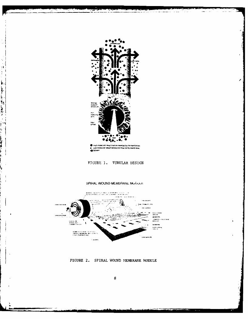
UF membranes are available in tubular, spiral wound, or flat disc design
(See Figures I and 2). The tubular design is comprised of a bundle of straw-
like tubes packed tightly inside a large diameter cylinder sealed at both
ends. The relatively large tube opening (1.1 mm) requires little or no
prefiltering and can be cleaned quite easily. The feed solution is pumped
through the openings in the ends of the tubes and permeate is forced out the
sides of the tubes by adjusting the back pressure. The velocity of the
solution going through the tubes creates a shear that removes build-up of
material from the membrane surface and thus permits running for long periods
of time before cleaning is necessary.
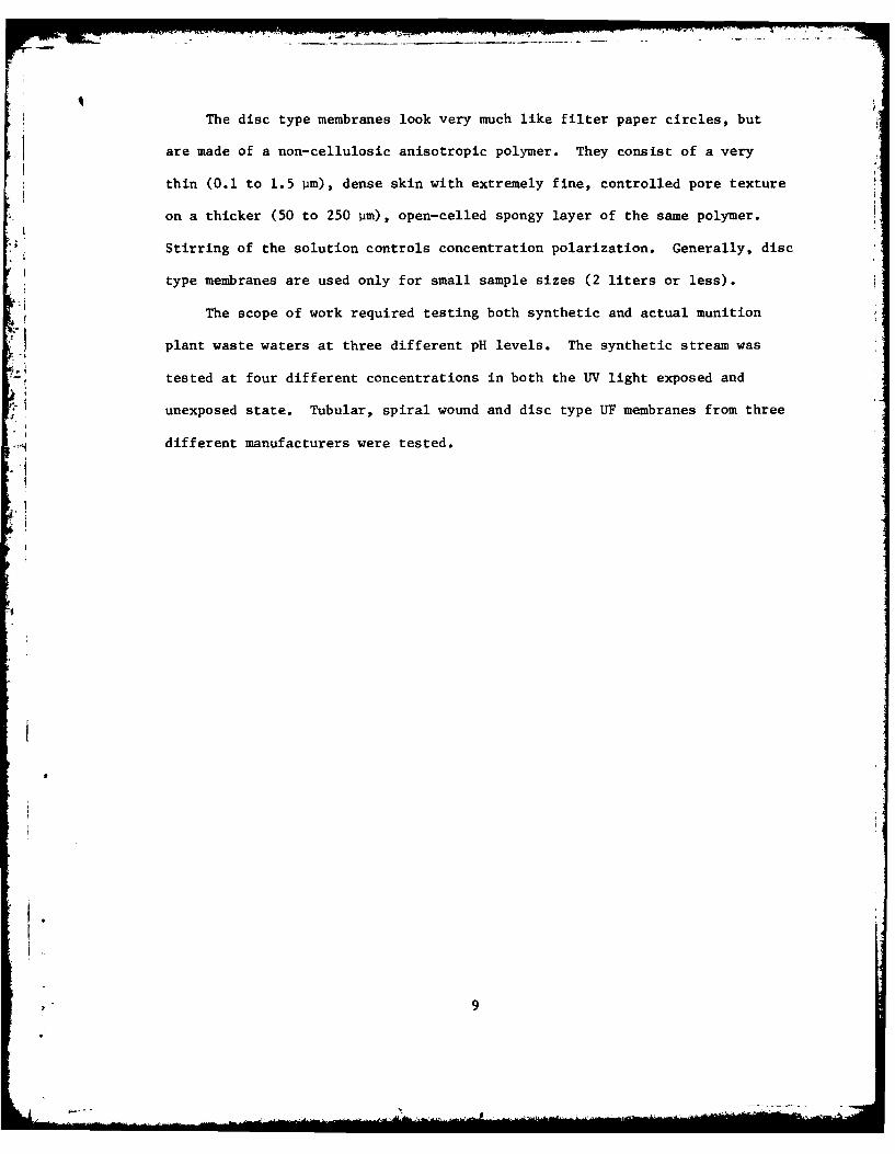
The spiral wound membrane is composed of a scroll-like configuration
consisting of alternating sheets of membrane and permeate carrier layers
which are attached to a perforated permeate tube (See Figure 2). The spacer
sheet between the two membranes serves to increase turbulence thus promoting
a higher mass transfer rate, to give strength to the membrane and to create
passages for flow. The spiral wound module has an exceptionally high membrane
area to volume ratio and is especially good for viscous solutions. One
drawback of the spiral wound module is that a 140 micron prefilter is required. 5
4C. R. Blodgett. 1975. Evaluation of Ultrafiltration as a Method for RemovingNitrocellulose Fines from Munition Plant Wastewater. Report EPA-IAG-DS-0753,Food Sciences Laboratory, US Army Natick Research and Development Command,Natick, MA.
5T. S. Shen, C. R. Hoffman. 1980. A Comparison of Ultrafiltration of LatexEmulsions and Macromolecular Solutions. Presentation, 5th Membrane Seminar,May 12, 1980, Clemson University, South Carolina.
7
00 0 e* 0 0
K 0
o e tct .0.
*04.e
* HIgh miolecular W1gt SolUte (MeetOt bty the -menenej9 L OWlCUler wight Slute(not reected by mnej*0S~l~t
FIGURE 1. TUBULAR DESIGN
SPIRAL WOUND MEMBRANE MUDULL
FIGURE 2. SPIRAL WOUND MEMBRANE MODULE
The disc type membranes look very much like filter paper circles, but
are made of a non-cellulosic anisotropic polymer. They consist of a very
thin (0.1 to 1.5 pm), dense skin with extremely fine, controlled pore texture
on a thicker (50 to 250 pm), open-celled spongy layer of the same polymer.
Stirring of the solution controls concentration polarization. Generally, disc
type membranes are used only for small sample sizes (2 liters or less).
The scope of work required testing both synthetic and actual munition
plant waste waters at three different pH levels. The synthetic stream was
tested at four different concentrations in both the UV light exposed and
unexposed state. Tubular, spiral wound and disc type UF membranes from three
different manufacturers were tested.
,.
APPROACH
Letters were sent to fifty manufacturers of membrane type systems
requesting their comments on the ultrafiltration of TNT, RDX aiid HMX waste
streams (See Appendix A). They were further asked to furnish literature
as well as the purchase or rental costs of their bench scale equipment.
Of the fourteen companies that replied, only four made bench scale equipment
* small enough for our sample size. Three companies stated that Reverse
Osmosis (RO) would work while others thought that UF might work, but RO
would probably be the better choice for compounds with such low molecular
weights. Romicon Corporation of Woburn, MA, was selected to furnish the
tubular UF membranes and equipment; Abcor Corporation of Wilmington, MA,
was chosen to supply the spiral wound UF membranes and Amicon Corporation
of Danvers, MA, was selected to furnish the disc type membranes.
A literature search to determine what previous work was done in this
area was made using the Defense Technical Information Center computer system
and S.D.C.'s Orbit IV International Search Service. Only seven references
were uncovered which are listed in Appendix B. The work by Bhattacharyya
and Garrison( on membrane ultrafiltration of TNT waste was the only reference
relevant to this study.
6Dibakar Bhattacharyya, Kenneth A. Garrison, and Robert B. Grieves. 1977.Membrane Ultrafiltration for Treatment and Water Reuse of TNT-ManufacturingWastes. Water Pollution Control Federation Journal, 49(5): 800-808.
10
MATERIALS AND METHODS
Chemicals
Practical grade 2,4,6-trinitrotoluene (TNT) containing 10% added water
was purchased from the Eastman Kodak Company, Rochester, NY. Hexahydro-
1,3,5-trinitro-l,3,5-triazine (RDX) in 50:50 ethanol: H20 solutions (lot
number 21-35) was obtained from Holston Army Ammunition Plant. Desensitized
octahydro-l,3,5,7-tetranitro-l,3,5,7-tetrazocine (HMX) (lot number SR-655-61)
was also obtained from Holston Army Ammunition Plant. All three chemicals
were washed with distilled H20, oven-dried at 650C for 24 hours, and placed in
a desiccator for several days before use.
The synthetic samples of TNT, RDX,and HMX were prepared by adding the
appropriate amount of each chemical to water at 950C and vigorously stirring
(1720 rpm) for 30 minutes. Not all of the chemicals would dissolve even using
this intense method. To overcome this problem 1/2 to 2% of acetone was added
to the water and the solubility was improved remarkably. The addition of
acetone had little or no effect on the UF results.
Munition Waste Streams
Samples from munition waste streams were obtained by Mr. Charles Denzler
of the US Army Toxic and Hazardous Materials Agency (USATHAMA), Aberdeen
Proving Ground, Maryland. These waste streams were taken from the Iowa Army
Ammunition Plant, the Milan Army Ammunition Plant, the Kansas Army Ammunition
Plant and the Lonestar Army Ammunition Plant.
Total Organic Carbon Analyzer
Total Organic Carbon (TOC) was determined by injecting a 40 uL sample into
a Beckman Total Organic Carbon Analyzer with a Beckman I.R. Detector, Model 915.
11
The combustion chamber was set at 9500 C, the flow rate at 150 cc/min and a
pressure of 0.35 kgf/cm2 (5.0 psig).
gHilh Performance Liquid Chromatography
Concentrations of TNT, HMX, and RDX were determined on a Waters Associates
Model 201/402 liquid chromatograph (LC) using a U.V. detector and a C-18 reverse
phase column. The mobile phase was 30% methanol and 70% water using a flow
rate of 1 cc/mmn and sample size of 50 PiL. Peak areas were determined by a
Hewlett-Packard Integrator, Model 3380A, programmed to give parts per million
(ppm) directly.
Total and Suspended Solids
Total solids were performed by placing a well-mixed 25 mL aliquot of the
950 C. The dried sample was cooled for 1 or more hours in a desiccator and
weighed. This cycle was repeated until a constant weight was obtained.
Suspended solids analysis was performed by passing a well-mixed 50 to
75 mL sample through a 0.45 pm type HA filter obtained from Millipore
Corporation. The pre-weighed filter was washed with distilled water and then
dried to a constant weight at 950 C. Samples were weighed on a Mettler, Gram-
Atic, balance which was accurate to 0.05 mg.
Ultrafiltration Equipment
The ultrafiltration runs were carried out using the Romicon HFXSMK11 and
HF2SSS ultrafiltration systems. The HFXSMKI1 system has a maximum flow rate
of 22.7 L/min (6 gal/min) while the HF2SSS has a maximum flow rate of 94.6 L/min
(25 gal/min). The inlet pressure for the smaller system was maintained at
1.75 kgf/cm2 (25 psig) while the outlet pressure was kept at 1.40 kgf/cm2
12
(20 psig). The larger system was run at an inlet pressure of 1.12 kgf/cm2
(16 psig) while the outlet pressure was 1.19 kgf/cm2 (17 psig). The smaller
ultrafiltration system was operated between 260 and 460 C while the large unit
was run at 260 to 350 C. Due to friction from the pump on the small ultrafilter
the temperature gradually rose as the run progressed. In the case of the
larger unit, which has an air pump, the temperature slowly fell as the run
progressed.
Ultrafiltration Membranes
The following three different Romicon hollow fiber membranes were tested:
P1I, PM2, and PM10. These membranes are constructed from a vinyl copolymer
having a membrane area of 0.1 m 2 (1.1 ft2 ) and an operating pH range of 1.5 to
13.0. A PMl membrane was also used in the large ultrafiltration unit and its
membrane area was 1.4 m2 (15 ft2).
Also tested were 2 spiral wound membranes having an area of 0.5 m2 (5 ft2 )
which were purchased from the Abcor Corporation. These were the S2HFK 130 VPO
and the S2HFM 100 VPO membranes. The small Romicon ultrafiltration system was
adapted by an Abcor Corporation technician to accept these membranes. This
was necessary because Abcor Corporation does not manufacture bench scale
ultrafilters. The Abcor membranes can be safely used in a pH range of 2 to 12,
at temperatures up to 900C and pressures up to 5.6 kgf/cm2 (80 psig). The
material of construction is proprietary and Abcor Corporation would not disclose
this information.
The final membrane tested was the UM05 membrane from Amicon Corporation. This
was a disc type (flat sheet) membrane with an anionic charge and was used with a
stirred cell, model 402. The molecular weight (MW) cut-off for this membrane was 500.
13

DISCUSSION
Twelve 19-liter (5 gallon) containers of munition waste were received
from each of the following Army Ammunition Plants: Iowa, Kansas, Lonestar,
and Milan. The individual containers were coarse filtered and blended
together to obtain a uniform sample from each plant. The average analysis
of the waste water from these plants is found in Table 1, below.
Table 1. Analysis of Waste Water from Four Army Ammunition Plants
Concentration Total Organic Carbon(ppm) (ppm)
Plant HMX RDX TNT Analyzer Theoretical
Iowa 2.1 13.9 94.4 66.4 37.5
Kansas 2.1 11.5 <0.3 188.0 2.3
Lonestar 3.4 27.0 26.4 51.2 14.69
Milan 7.7 70.2 98.5 75.7 49.07
Despite the care taken in blending samples, there were some discrepancies in
LC values for the HMX, RDX, and TNT from run to run. This may have been caused
* by quantities of each ingredient precipitating out of solution during storage
at 50C even though the samples were heated to at least 260 C and shaken prior
to analysis. The RDX value in Table 1 for the Milan Army Ammunition Plant
exceeds its water solubility. This is probably due to the presence of
organic solvent used in the manufacture of RDX. When comparing the total
organic carbon (TOC) values obtained from the Beckman Analyzer with the values
obtained by a carbon balance from the Waters LC, we see a very large difference,
especially for the Kansas Army Ammunition Plant. This shows that these waste
14
waters contained large amounts of other organic compounds. This is verified
by the chromatogram which shows 11 peaks for the Milan waste stream and 8
peaks for the waste streams from the other 3 plants.
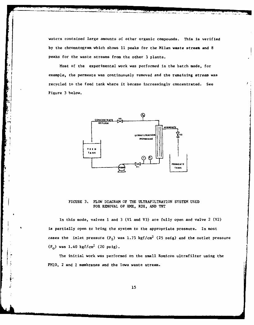
Most of the experimental work was performed in the batch mode, for
example, the permeate was continuously removed and the remaining stream was
recycled to the feed tank where it became increasingly concentrated. See
Figure 3 below.
CONCENTRATE 1
~RITUtNi ' PERMEATE
ULTRAFILTRtATION V
MEMISRANE
F E
TANK
J.. IIAN
.
FIGURE 3. FLOW DIAGRAM OF THE ULTRAFILTRATION SYSTEM USEDFOR REMOVAL OF HMX, RDX, AND TNT
In this mode, valves I and 3 (Vi and V3) are fully open and valve 2 (V2)
is partially open to bring the system to the appropriate pressure. In most
cases the inlet pressure (Pi) was 1.75 kgf/cm 2 (25 psig) and the outlet pressure
(Po) was 1.40 kgf/cm2 (20 psig).
The initial work was performed on the small Romicon ultrafilter using the
PMIO, 2 and 1 membranes and the Iowa waste stream.
15

Table 2. Summary of Results Using 3 Ultrafiltration Membranes at 3 pHLevels on the Iowa Ammunition Plant Waste Stream
PERCENT REMOVED
FLUXDissolved Suspended
Membrane pH (L/m2-h) HMX RDX TNT TOC Solids (ppm) Solids (ppm)
3.0 182.5 0 1.7 17.3 20.8 68.0 76.3
PM10 7.0 203.7 9.2 2.0 14.4 18.5 0 92.7
11.0 260.9 44.1 1.9 -- 10.0 3.3 96.2
3.0 53.8 0 0 15.6 16.0 10.7 97.1
PM2 7.0 75.7 0 0 9.5 7.7 0 89.1
11.0 41.9 0 0 -- 10.5 40.1 98.4
3.0 17.5 0 1.6 34.2 34.6 0 92.0
PMl 7.0 23.5 0 0 25.4 20.7 0 98.1
11.0 37.7 36.4 49.9 -- 18.9 19.8 99.1
Table 2 shows that the PMl membrane was superior to the other two membranes
because it permitted more TNT and TOC removal. The figures were calculated by
comparing the permeate LC values to the feed LC values. Best TNT removal was
obtained at pH 3.0. The flux at pH 3.0 was generally not as high as at pH 7.0.
It can also be seen that most of the suspended solids were removed by the PMl and
PM2 membranes. Because the best results in the above experiments were obtained
on the PMI membrane, it was selected for further testing with both the synthetic
and the additional munition plant waste streams.
Additional experiments were performed with the PMl membrane using 70 ppm
TNT, 30 ppm RDX and 10 ppm HMX as our full strength base. We then made up
16
additional concentrations of 2x, l/2x and 1/4x. Because of solubility
problems, especially at the higher levels (2x) one to two percent acetone was
added for some of the runs. Even when using acetone we were only able to
solubilize 115.8 ppm TNT, 46.1 ppm RDX, and a surprisingly low 9.7 ppm HMX.
Unfortunately, the addition of acetone prevented accurate TOC measurements
for 7 of 16 acid runs, 9 of 20 neutral runs, and 2 of 7 base runs because of
Sevaporation while passing through the ultrafilter. A summary of the results
'.1 using the small PMl membrane is found in Table 3.
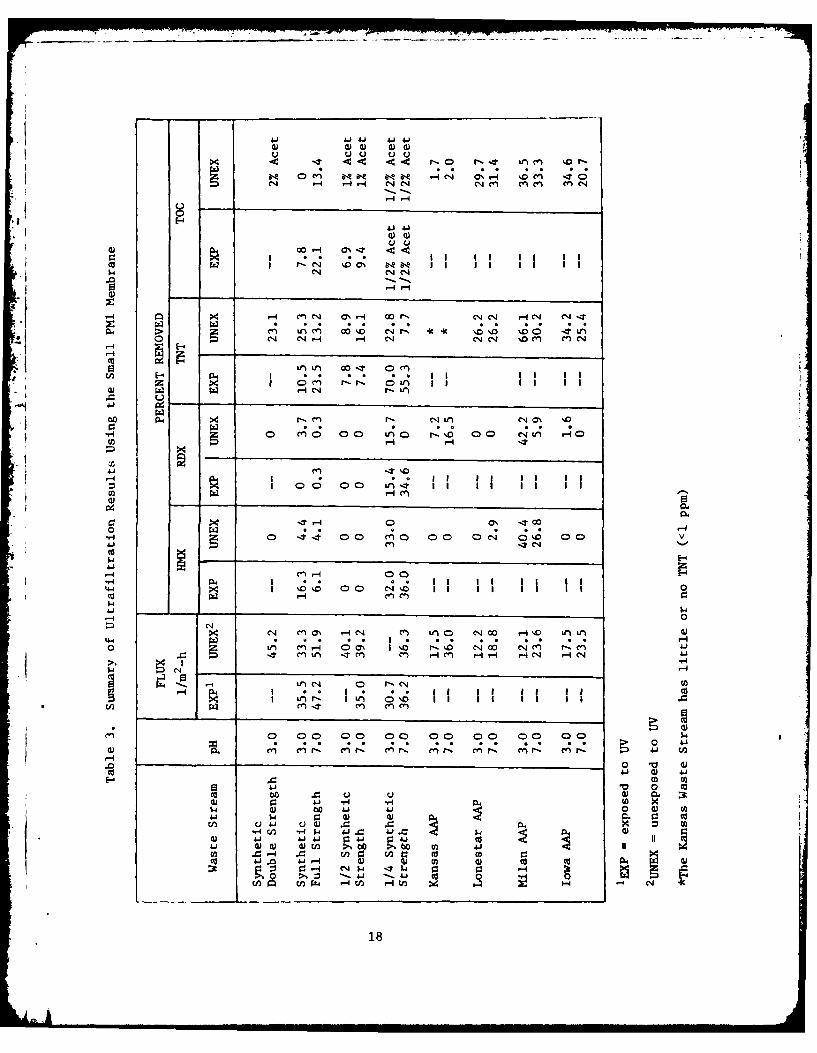
Table 3 shows that the highest flux rates occurred at pH 7.0 and that
generally pH 3.0 was better than pH 7.0 for TNT removal (an average of 29.5%
vs. 19.8%). It is interesting to note that the percent TNT removal was
higher for the munition plant waste streams than it was for the synthetic
waste streams. The results for the TA-exposed waste vs. the unexposed waste
indicated no appreciable difference at full strength and half strength, but
at 1/4 strength considerably more UV-exposed TNT is removed. The results for
HMX and RDX were quite erratic with many runs showing no removal while others
showed up to 40% removal. Also, in some cases pH 3.0 was best while in others
pH 7.0 is best.
To obtain good scale-up data, 9 experiments were run using the large PMl
membrane on the large Romicon ultrafilter. There was no significant
difference in TNT removal at either pH 3.0 or pH 7.0 for the actual munition
waste streams, but pH 7.0 was better for the synthetic stream (See Table 4).
Comparing these values with those in Table 3 we find that in most cases the
larger column was superior. Once again, pH 7.0 generally gave higher flux
rates than pH 3.0 and the large PMl membrane gave lower flux rates than the
small PMl membrane.
17
I? -cc -cc -. r- 0 r-- IT %r-n
014~~~~~~- -4- .-N4 4M nme
%D ON 811 DO I
r-4 1- en Ifi m I- 00I q -
8 -4r
to4P >4 r- 4n r-) C N -4C %D-~
0 C
H ** 0 C' ) 0C'4Lf N C'40 'O0
P4- 00O
005.04
44 r-4 0
-It 00) II IT cn C) le I 4 4C4 rlC4A
X c'J ~L .-S14 4 C-4 u 0 ' ,5 LfI )r: ~ *z i I I * I I i . i
o Lf) C 0O C 0 C)~ 04 C)C' T0~ .
4 4 CrZ -. C4 C9 c4c 0- 4-C -~
0 0 m
04 Q) 00 Aj 4 0 ) c
0)~1 P. Y- .-1-. w) 05) mi L )
4.4 4.4 ) )C, 4. 0 q) w. 0 U)
94C/) *d$4 Li. .00) 4. --. ~ 41 ~ 41 0 I II
CA to. 4.i4 0) W 0r- U) 14 04 P 0
18
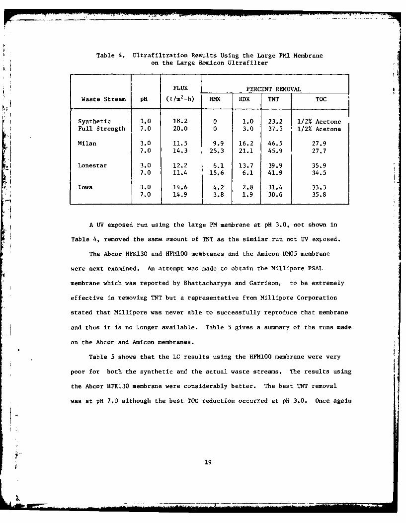
Table 4. Ultrafiltration Results Using the Large PMI Membrane
on the Large Romicon Ultrafilter
FLUX PERCENT REMOVAL
Waste Stream pH (i/m2-h) HMX RDX TNT TOC
Synthetic 3.0 18.2 0 1.0 23.2 1/2% Acetone
Full Strength 7.0 20.0 0 3.0 37.5 1/2% Acetone
Milan 3.0 11.5 9.9 16.2 46.5 27.97.0 14.3 25.3 21.1 45.9 27.7
.1 Lonestar 3.0 12.2 6.1 13.7 39.9 35.97.0 11.4 15.6 6.1 41.9 34.5
Iowa 3.0 14.6 4.2 2.8 31.4 33.37,0 14,9 3.8 1.9 30.6 35.8
A UV exposed run using the large PM membrane at pH 3.0, not shown in
Table 4, removed the same 2mount of TNT as the similar run not UV exposed.
The Abcor HFK130 and HF10 membranes and the Amicon UM05 membrane
were next examined. An attempt was made to obtain the Millipore PSAL
membrane which was reported by Bhattacharyya and Garrison, to be extremely
effective in removing TNT but a representative from Millipore Corporation
stated that Millipore was never able to successfully reproduce that membrane
and thus it is no longer available. Table 5 gives a summary of the runs made
on the Abcor and Amicon membranes.
Table 5 shows that the LC results using the HFM100 membrane were very
poor for both the synthetic and the actual waste streams. The results using
the Abcor HFK130 membrane were considerably better. The best TNT removal
was at pH 7.0 although the best TOC reduction occurred at pH 3.0. Once again
I-1
19
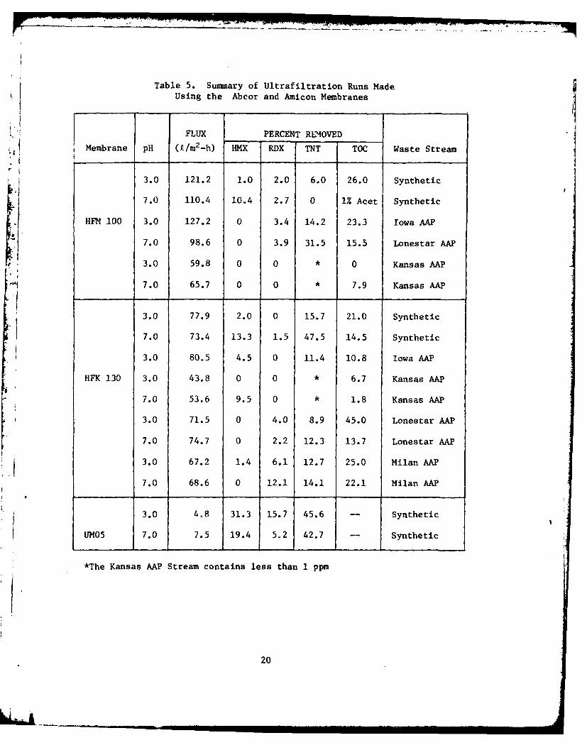
Table 5. Summary of Ultrafiltration Runs MadeUsing the Abcor and Amicon Membranes
FLUX PERCENT REMOVED
Membrane pH (k/m2 -h) HMX RDX TNT TOC Waste Stream
3.0 121.2 1.0 2.0 6.0 26.0 Synthetic
7.0 110.4 10.4 2.7 0 1% Acet Synthetic
HFM 100 3.0 127.2 0 3.4 14.2 23.3 Iowa AAP
7.0 98.6 0 3.9 31.5 15.5 Lonestar AAP
3.0 59.8 0 0 * 0 Kansas AAP
7.0 65.7 0 0 * 7.9 Kansas AAP
3.0 77.9 2.0 0 15.7 21.0 Synthetic
7.0 73.4 13.3 1.5 47.5 14.5 Synthetic
3.0 80.5 4.5 0 11.4 10.8 Iowa AAP
HFK 130 3.0 43.8 0 0 * 6.7 Kansas AAP
7.0 53.6 9.5 0 * 1.8 Kansas AAP
3.0 71.5 0 4.0 8.9 45.0 Lonestar AAP
7.0 74.7 0 2.2 12.3 13.7 Lonestar AAP
3.0 67.2 1.4 6.1 12.7 25.0 Milan AAP
7.0 68.6 0 12.1 14.1 22.1 Milan AAP
3.0 4.8 31.3 15.7 45.6 -- Synthetic
UM05 7.0 7.5 19.4 5.2 42.7 -- Synthetic
* *The Kansas AAP Stream contains less than 1 ppm
20
the results for HMX and RDX removal were somewhat erratic at both pH 3.0 and
pH 7.0 with neither pH showing very good removal. The flux rates were higher
than those obtained with the PMI membrane with an average of 68.2 L/m 2-h at
pH 3.0 and 67.6 L/m2-h at pH 7.0.
The final membrane tested was the Amicon UM05. Table 5 shows that at
either pH 3.0 or 7.0 over 42% of the TNT from a synthetic stream was removed.
PH 3.0 was best for the removal of HMX and RDX with removals of 31.3 and
15.7%, respectively. However, the flux rates were extremely poor, especially
at pH 3.0.
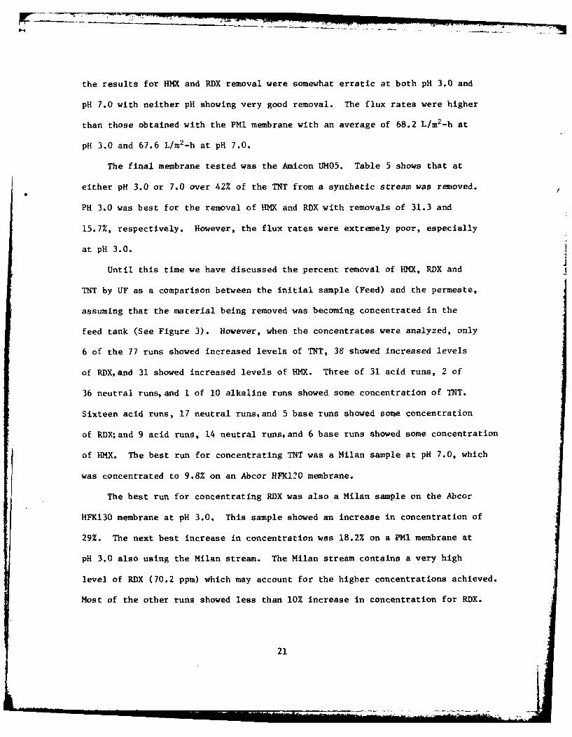
Until this time we have discussed the percent removal of HMX, RDX and
TNT by UF as a comparison between the initial sample (Feed) and the permeate,
assuming that the material being removed was becoming concentrated in the
feed tank (See Figure 3). However, when the concentrates were analyzed, only
6 of the 77 runs showed increased levels of TNT, 38 showed increased levels
of RDX,and 31 showed increased levels of HMX. Three of 31 acid runs, 2 of
36 neutral runs, and I of 10 alkaline runs showed some concentration of TNT.
Sixteen acid runs, 17 neutral runs,and 5 base runs showed some concentration
of RDX;and 9 acid runs, 14 neutral runs, and 6 base runs showed some concentration
of HMX. The best run for concentrating TNT was a Milan sample at pH 7.0, which
was concentrated to 9.8% on an Abcor HFKI2O membrane.
The best run for concentrating RDX was also a Milan sample on the Abcor
HFK130 membrane at pH 3.0. This sample showed an increase in concentration of
29%. The next best increase in concentration was 18.2% on a PMI membrane at
pH 3.0 also using the Milan stream. The Milan stream contains a very high
level of RDX (70.2 ppm) which may account for the higher concentrations achieved.
Most of the other runs showed less than 10% increase in concentration for RDX.
21
For HMX a maximum increase in concentration of 53.8% was achieved at pH
3.0 using the PMi membrane on the Milan stream. There were several other
good runs showing concentration increases of 31 to 43% at pH 3.0 using the
PMI membrane.
Material and carbon balances were performed on many of the ultrafiltration
runs to determine the fate of the HMX, RDX,and TNT being removed but not found
in the concentrate.
An example of these calculations is found in Appendix C. These
calculations show that the material balances do not balance and therefore
material must be adsorbing on the surfaces of the membranes.
To verify our theory that the material was being lost due to adsorption
we flushed a membrane for 30 minutes with 1% NaOH and analyzed the resultant
solution. The solution was cloudy and had an intense brownish-orange color.
The LC analysis revealed no TNT, RDX,or HMX, but very large peaks were found
at retention times of 1.7, 2.3, 2.9, 3.2,and 4.3 which are typical of the
decomposition products of these compounds (see Figure 4).
To circumvent the problem of decomposition from NaOH we next flushed a
membrane for 30 minutes with 10 liters of a 2% acetone solution immediately
following another run. An analysis of this sample revealed trace levels of
RDX, a slightly higher level of HMX (1.3 ppm) and a significant level of TNT
(7.1 ppm). This accounted for 92.5% of the starting material. It is believed
that a longer flush would have removed even more material because a sodium
hydroxide flush of the membrane after the acetone flush still produced the
brownish-orange color. See Figures 5 and 6 for examples of HPLC chromatograms
showing the effect of NaOH on HMX, RDX,and TNT.
To determine if the membranes could become fouled if run longer than
the 2 to 4 hours of a typical run, we conducted a run for 2 days with the Abcor
22
e~0mW
109
xcru151
1 0
'.44
to 0 ,
0
b440
00
ii %t) t
23
130 membrane using total recycle (valves 1 and 2 open and valve 3 closed).
(See Figure 3). There was no change in the flux rates after this period
indicating that the membrane was not becoming plugged. This was probably due
to the low concentration of HMX, RDX,and TNT in the full-strength synthetic
stream.
A similar run was made on the Iowa waste stream using the PMI membrane
and a 20% reduction in flux was found over 2 days.
Another run of interest was performed using the large PMI membrane and
a large volume of synthetic waste at pH 7.0. The run lasted 5 hours and there
was a 21.5% reduction in flux rate. Part of this drop could be due to a
temperature drop from 400 to 350 C as the run progressed. In this run, samples
of the concentrate and feed were taken every 30 minutes and analyzed on the
HPLC. The highest rate of TNT removal occurred in the first hour with a
decreasing rate of removal over the next 4 hours. This is typical of
adsorption where molecules quickly adsorb on a surface and the rate declines
rapidly because of fewer available sites.
Although no ultrafiltration membrane was very effective for concentrating
TNT, it was interesting to note that nearly all the permeate streams were free
of color bodies and in most cases the concentrates were considerably darker
than the feed solutions.
24
CONCLUS IONS
Ultrafiltration using the membranes currently available is not effective
for the removal of soluble quantities of HMX, RDXand TNT from munition plant
waste waters. However, suspended solids are removed and generally there is
a concentrating of other organic compounds in the actual waste streams.
Because ultrafiltration is not effective, it was not possible to determine1plant costs using ultrafiltration.
II
ttThis document reports research undertaken at
i the US Army Natick Research and Develop-ment Command and has been assigned No.
NATICK/TR-f_,!gJ ._.'in the series of re-
ports approved for publication.
25'
LITERATURE CITED
1. Burlinson, N. E., M. E. Sitzmann, D. J. Glover, and L. A. Kaplan. 1979.Photochemistry of TNT and Related Nitroaromatics: Part III. TechnicalReport NSWC/WOL TR 78-198, Naval Surface Weapons Center, Silver Spring, MD.
2. Andren, R. K., J. M. Nystrom, R. J. Erickson. 1975. Treatment of TNT
Munitions Wastewaters Using Polymeric Adsorption Resins. Food Sciences
Laboratory, US Army Natick Research and Development Command, Natick, MA.
3. Crampton, M. R. 1973. Stabilities of Meisenheimer Complexes. J. Chem.Vt Soc., Perkin Trans 2, 1973, (6), 710-15 (Eng).
Sj4. Blodgett, C. R. 1975. Evaluation of Ultrafiltration as a Method forRemoving Nitrocellulose Fines from Munition Plant Wastewater. Report
-. EPA-IAG-DS-0753, Food Sciences Laboratory, US Army Natick Research andDevelopment Command, Natick, MA.
5. Shen, T. S., C. R. Hoffman. 1980. A Comparison of Ultrafiltration ofLatex Emulsions and Macromolecular Solutions. Presentation, 5th MembraneSeminar, Clemson University, South Carolina.
6. Bhattacharyya, Dibakar, K. A. Garrison. 1977. Membrane Ultrafiltrationfor Treatment and Water Reuse of TNT Manufacturing Wastes. Water PollutionControl Federation Journal, 49(5): 800-808.
2
26
APPENDIX A
Manufacturers of Membrane Equipment That Were Contacted
*Abcor Inc. *Damrow Co.850 Main Street Fond Du Lac, WI 54935Wilmington, MA 01887
De Salination Systems, Inc.Ajax International Corp. 1107 W. Mission Ave.P.O. Box 26607 Escondido, CA 92025San Diego, CA 92126
Dorr OliverAqua-Chem Inc. 274 Riverside Ave.Water Technologies Division Westport, CT 06880P.O. Box 421Milwaukee, WI 53201 Dow Chemical Co.
2020 Dow Center
*Amicon Corp. Midland, MI 48640182 Conant StreetDanvers, MA 01923 DuPont, E. I. De Nemours & Co.
Wilmington, DE 19898*Barnstead Co.
225 Rivermoor Street Ecodyne Corp. Craver Water Div.Boston, MA 02132 2720 US Highway 22
Union, NJ 07083*Basic Technologies Inc.1744 Donna Road El Paso Environmental Systems Inc.W. Palm Beach, FL 33409 123 N. Concepcion Street
P.O. Box 10751CPAC Inc. El Paso, TX 799972364 Leicester RoadLeicester, NY 14481 Envirex Inc.
1901 S. Praire Ave.Chemtronic Systems Inc. Waukesha, WI 531863540 Lightner Blvd.P.O. Box 85 *Envirogenics Systems Co.Vandalia, OH 45377 9255 Telstar Ave.
El Monte, CA 91731Cochrane Environmental Systems
Crane Co. *Flotronics Div Selas Corp. of AmericaP.O. Box 191 1957 Pioneer RoadKing of Prussia, PA 19406 Huntingdon Valley, PA 19006
*Continental Water Systems Corp. *Gaston County FabricationP.O. Box 20018 P.O. Box 308El Paso, Texas 19998 Stanley, NC 28164
Culligan USA Gelman Sciences Inc.One Culligan Parkway 600 S. Wanger Rd.Northbrook, IL 60062 Ann Arbor, MI 48106
*Replied to Letter
27
APPENDIX A (continued)
Go-Ten Manufacturing *Penfield Inc.P.O. Box 8237 980 Old Colony RoadTrenton, NJ 08650 Meriden, CT 06450
Griffolyn Co. Permutit, NJ110020 Mykawa Box 355
Box 33248 Paramus, NJ 07670Houston, TX 77033
Polymer Research Corp. of AmericaHex Industries Inc. 2186 Mill Ave.15001 S. Figueroa Street Brooklyn, NY 11234Gardena, CA 90248
Polymetrics Inc.Illinois Water Treatment Co. 1005 Timothy Drive
4669 Shepherd Trail San Jose, CA 95133Rockford, IL 61105
Rexnord Inc.Infilco Degremont Inc. P.O. Box 2022Box K-7 Milwaukee, WI 52314Richmond, VA 23288
*Romicon Inc.Ion Exchange Products Inc. 100 Cummings Park
4500 N. Clark Street Woburn, MA 01801
Chicago, IL 60640Saltech Inc.
lonics Inc. P.O. Box 2687265 Grove Street El Paso, TX 79926Watertown, MA 02172
Scott Environmental Div. EnvironmentalLA Water Treatment Div. Chromallox Tectonics Corp.
American Corp. James WayBox 1467 Southampton, PA 18966City of Industry, CA 91749
*Sethco Div. Met Pro Corp.
Liquitech Div of Thermotic Inc. 39 Bennington Ave.P.O. Box 13030 Freeport, NYHouston, TX 77019
*UOP, Fluid System Div.
National Tank and Pipe Co. 2980 N. Harbor DriveP.O. Box 7 San Diego, CA 9210110037 SE Mather RoadClackamas, OR 97015 Vaponics, Vaponics Ltd.
Cordage Park*Osmonics Inc. Plymouth, MA 02360
15404 Industrial RoadHopkins, MN 55343
*Replied to Letter
28
APPENDIX A (continued)
Water Purification Systems, Inc.3451E 26th StreetLos Angeles, CA 90023
Water Services of America Inc.P.O. Box 234218165 W. Tower Ave.Milwaukee, WI 53223
Western Dynetics Inc.1152 Tourmaline DriveNewbury Park, CA 91320
Westinghouse Electric Corp.Gateway CenterPittsburg, PA 15222
Xonics Inc.6849 Hayvenhurst Ave.
Van Nuys, CA 91406
29

APPENDIX B
Literature Search Finds
* 1. Puzatkima, L. A. 1971. Purification of Waste Waters by Filtration ThroughFinely Divided Activated Carbon. Sbtr., Mosk. Inzhstroit Inst. (SISKAZ),V. No. 87, p. 123-7. USSR.
2. Okamoto, Y.; Chou, E. J.; Wang, J.; Roth, M. 1977. The Removal of TNTfrom Aqueous Solution with Surfactants. Pub.: Inf. Transfer, Inc.,Rockville, MD.
.1 3. Stilwell, J. M.; Eischen, M. A.; Margard, W. L.; Matthews, M. C.; Stanford,T. B. 1977. Toxicological Investigations of Pilot Treatment PlantWastewater at Holston Army Ammunition Plant. U.S. NTIS, AD Rep. (AD -
, IA042601) 56 pp.
4. Vlahakis, John G. 1974. A Laboratory Study of RDX Absorption by Carbon.NTIS Report AD/A-002 049, (45).
5. Patterson, J. W.; Shapira, N. I.; Brown, J. 1976. Pollution Abatement
in the Military Explosives Industry. Presented at Purdue UniversityIndustrial Waste 31st Conference, Lafayette, p. 385(10).
6. Bhattacharyya, Dibakar; Garrison, Kenneth A. 1977. Membrane Ultrafiltrationfor Treatment and Water Reuse of TNT Manufacturing Wastes. Water PollutionControl Federation Journal, 49(5): 800-808.
30

APPENDIX C
MATERIAL BALANCE CALCULATIONS
Run 36 Milan pH 7.0 PM1 Membrane
CONCENTRATION (mg/L)
Compound Initial Permeate Concentrate_ _
HMX 9.7 7.1 8.3RDX 70.6 66.4 79.2TNT 93.7 65.4 79.6
TOTAL 174.0 138.9 167.1
Weights
Starting material (initial) .... 18.11 kgPermeate .................... 10.00 kgConcentrate .................... 8.00 kg
Initial (I) - 174.0 mg/L
174.0 (18.11) = 3,151.1 mg
Permeate (P) - 138.9 mg/L
138.9 (10.00) = 1,389.0 mg
Concentrate (C) - 167.1 mg/L
167.1 (8.00) = 1,336.8 mg
I = P + C + A (material adsorbed on membrane)
3,151 - 1,389.0 + 1,336.8 + A
A = 425.3 mg of material adsorbed on membrane
31
* I
APPENDIX C (CONT'D)
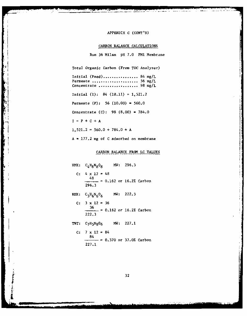
I CARBON BALANCE CALCULATIONS
Run 36 Milan pH 7.0 PMl Membrane
Total Organic Carbon (From TOC Analyzer)
Initial (Feed) ................ 84 mg/L I'Permeate ..................... 56 mg/LConcentrate .................. 98 mg/L
Initial (I): 84 (18.11) = 1,521.2
Permeate (P): 56 (10.00) = 560.0
Concentrate (C): 98 (8.00) = 784.0
I =P+C+A,I.1,521.2 = 560.0 + 784.0 + A
A = 177.2 mg of C adsorbed on membrane
CARBON BALANCE FROM LC VALUES
HMX: C4H8N8 08 MW: 296.3
C: 4 x 12 = 48~48 48 =- 0.162 or 16.2% Carbon
296.3
RDX: CHN0 MW: 222.3
C: 3 x 12 3636
0.162 or 16.2% Carbon222.3
TNT: C7H5N806 MW: 227.1
C: 7 x 12 - 8484
= 0.370 or 37.0% Carbon227.1
32
r.Sm -J --' _ .i i " k, _ _ : .:: - ... .. ...... .4 ... .. . _ ._ L : .: . .... . .-
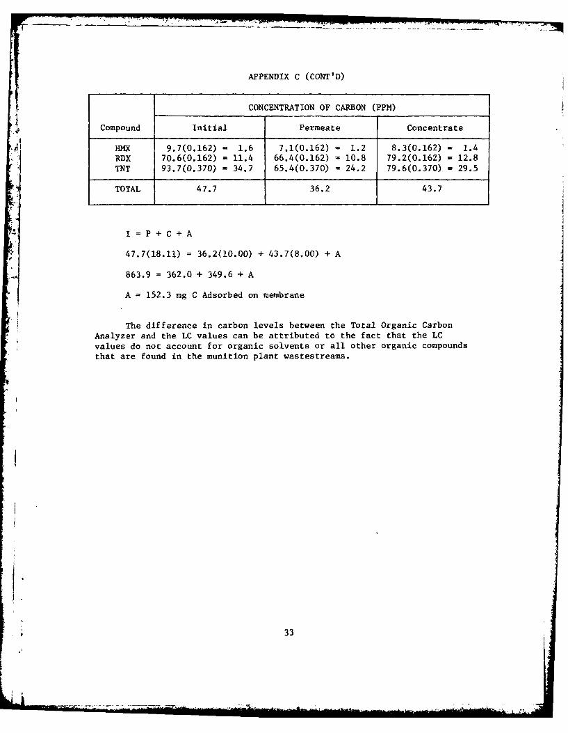
APPENDIX C (CONT'D)
CONCENTRATION OF CARBON (PPM)
Compound Initial Permeate Concentrate
HMX 9.7(0.162) = 1.6 7.1(0.162) = 1.2 8.3(0.162) = 1.4
RDX 70.6(0.162) = 11.4 66.4(0.162) = 10.8 79.2(0.162) = 12.8TNT 93.7(0.370) = 34.7 65.4(0.370) = 24.2 79.6(0.370) = 29.5
TOTAL 47.7 36.2 43.7
If=fP+C+A
47.7(18.11) = 36.2(10.00) + 43.7(8.00) + A
863.9 = 362.0 + 349.6 + A
A = 152.3 mg C Adsorbed on membrane
The difference in carbon levels between the Total Organic CarbonAnalyzer and the LC values can be attributed to the fact that the LCvalues do not account for organic solvents or all other organic compoundsthat are found in the munition plant wastestreams.
33
L t