uk unlimited atomic weapons research establishment …
TRANSCRIPT

UK UNLIMITED
ATOMIC WEAPONS RESEARCH ESTABLISHMENT
AWRE REPORT NO. 07/83
An On-Line Seismometer Array Processor
S V New
Recommended for issue by
A Douglas, Acting Superintendent
Approved
F E Whiteway, Head of Division
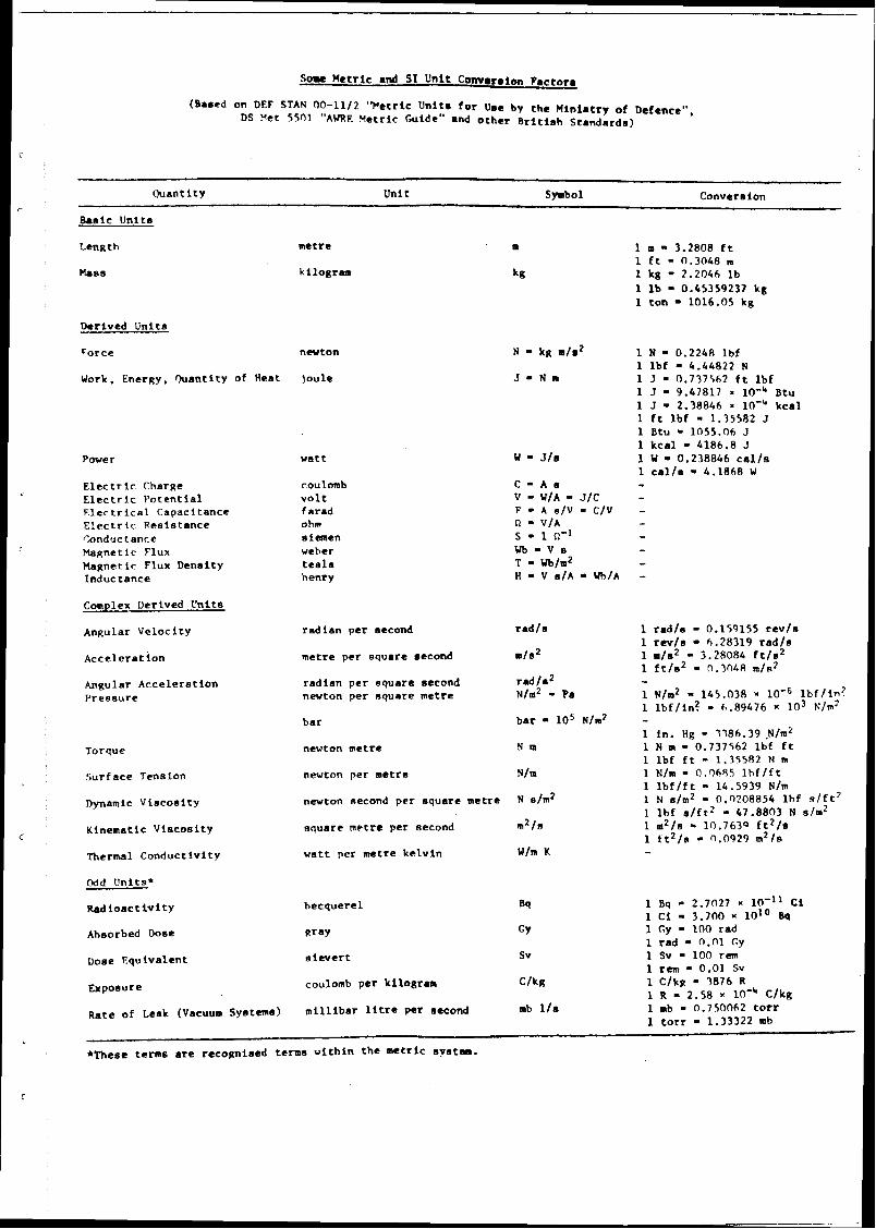
S o w Met r i c and S1 Uni t C o w e r a i m F a c t o r s
(Based on DEF STAN 00-1112 "Metr ic U n i t s f o r Use by t h e U i n i a t r y o f Defence", DS Yet 5501 "AURE Metr ic Guide" and o t h e r B r i t i s h S t anda rds )
Quan t i t y Un i t Symbol Conversion
Basic Un i t s
Derived U n i t s
Force
Work. Energy. Ouan t l t y o f Heat
Power
E l e c t r i c Charge E l e c t r l c P o t e n t i a l F l e r t r i c a l Capaci tance E l e c t r i c Ree t s t ance I:onductance Naqne t i c Flux Magnet i c Flux Dens i t y Induc tance
Complex Derived U n i t s
Angular V e l o c i t y
A n ~ u l a r A c c e l e r a t i o n P r e s s u r e
Torque
Surf a c e Tension
Dynamic ViScositY
Kinemat ic V i s c o s i t y
Thermal Conduc t iv i ty
me t r e
k i logram
newton
j o u l e
w a t t
coulomb v o l t f a r a d ohm a l w e n weher t e e l a henry
r a d i a n pe r second
me t r e per s q u a r e second
r a d i a n p e r s q u a r e second newton pe r squa re me t r e
b a r
newton metre
nevton per me t r e
nevton ~ e c o n d p e r s q u a r e me t r e
1 m - 3.2808 f t l f t - 0.3048 m 1 kg - 2.2046 l b 1 l b - 0.45359237 kg 1 t o n - 1016.05 kg
l N - 0.2248 lb f l l b f 4.44822 N l J - 0.737562 f t l b f 1 J - 9.47817 x 10-'' Btu 1 J - 2.38846 X kc.1 1 f t l b f * 1.35582 J 1 Btu - 1055.06 J 1 k c a l - 4186.8 J 1 W - 0.238846 c a l l s 1 c a l / o - 4.1868 W -
r a d / r l r a d / s - 0.159155 r e v / s 1 rw/s - 6.28319 r a d / s
m/s2 1 m/s2 - 3.28084 f t / s 2 1 f t / s 2 - 0.7048 m/n2
r a d / s 2 - ~ / m ' - Pa 1 ~ / m ~ - 145.038 10'~ l b f l l n ?
1 l b f l i n ? - 6.89476 x 10³ plm7 b a r l o 5 ~ / m ' -
1 i n . Hg - 1186.39 . ~ / r n ~ N m 1 N m - 0.737562 l b f f t
1 l b f f t - 1.35582 N m N/m 1 N/m - 0.0685 l b f l f t
1 l b f l f t - 14.5939 N/m N elm2 1 N slm2 - 0.n208854 l h f s / f t 7
1 l b f s / f t 2 - 47.8803 N s/m2 nquare me t r e pe r second m 2 / s
w a t t pe r me t r e k e l v i n W/m K
Odd Un i t s f
R a d i o a c t i v i t y hecque re l 1 ~q - 2 . 7 ~ 7 X 10-l' C% 1 Ci - 3.700 X 1 0 l o Bq
Ahsorbed Dose w a y GY 1 Gy - 100 rad l r e d - n.nl Cy
Dose Equ tva l en t s i c v e r t Sv 1 Sv - 100 r m 1 rem - 0.01 Sv
Exposure coulomb pe r k i logram C/kg 1 C/kg - 0876 R 1 R - 2.58 10-h c l k g
Ra te o f Leak (Vacuum Systems) m i l l i b a r l i t r e pe r second mb l/s 1 mb - 0,750062 t o r r 1 t o r r - 1.33322 mb
*These t e n s a r e r ecogn i sed terms w i t h i n t h e m e t r i c syet-.

ISBN 0 85518152 4
CONTENTS
SUMMARY
THE ESKDALEMUIR ARRAY
ARRAY PROCESSORS AND THE ON-LINE CORRELATOR
THE DESIGN AND DEVELOPMENT O F THE OSAP
Outline of processing rriethod Some detai ls of sof tware
PERFORMANCE
CONCLUSIONS
APPENDIX A: SPECIFICATIONS
APPENDIX B: CO-ORDINATES O F BEAMS PROJECTED ON TO THE EARTH'S SURFACE
FIGURES 1 - 11
Page
3
3

SUMMARY
The design, development and performance of an On-line Seismo- mete r Array Processor (OSAP) is described. The purpose of an OSAP is to: receive the digitised signals (sampled 20 t imes per second) from each of 20 seismometers of a 10 km aper ture array of t h e UK-type; de tec t seismic signals with a signal-to-noise ra t io of about two or greater; e s t imate t he epicentres of t h e sources of t he signals; record t he signal da t a on flexible magnetic (floppy) disc and display t he signal information on a char t recorder. The prototype OSAP has a Computer Automation Inc LSI-2 minicomputer a s i t s centra l processor and has been operating satisfactorily at the Eskdalemuir array, Scotland since February 1980. The log-detector algorithm of Weichert is used in t he OSAP a s this non-linear algorithm is much be t te r than a linear detector at discriminating between detections due t o t rue signals and those due t o da t a errors, particularly large amplitude excursions of short duration ("spikes").
The experience gained in this study suggests t ha t i t should be possible t o have almost complete automation of t he routine running of an array station of t h e EKA-type, including: t h e checking of t he systern for faults; t h e calibration of the recording system; and t he detection and routine analysis of signals of significant amplitude. At such an automated station t he staff would be able t o concentra te on array maintenance. I t seems possible tha t a fairly inexpensive processor based on two minicomputers could be developed t o run t h e 25 km aper ture UK-type arrays and provide all t h e facilities available in t he currently used off-line processors (SASPs).
INTRODUCTION
Research over the past twenty years has demonstrated t ha t arrays of seismometers can be used t o improve t he signal-to-noise ra t io of t h e shor t period (SP) P waves radiated by earthquakes and explosions. Most of this work has been aimed at finding ways of detecting and identifying low-yield ( - l kton) explosions from t h e seismic signals they generate. To find weak signals hidden in noise requires a processor tha t can combine in some way t he outputs of t h e seismometers in an array. The obvious way t o make such a processor is t o build i t around a general purpose digital computer and several such processors a r e in operation. Three of the UK-type arrays (Gauribidanur, India (GBA), Warramunga, Australia (WRA), and Yellowknife, Canada (YKA)) from which MOD(PE), Blacknest receive da t a a r e already equipped with such processing systems. These processors a r e built around Digital Equipment Corporation PDPl l s . The processor at the YKA array was developed by t he seismology section of t he Canadian Department of Energy, Mines and Resources and is described by Weichert and Henger (1). The processors at GBA and WRA - called SASPs - were developed by MOD(PE) and a r e described by Key, Lea and Douglas (2).

This report describes a second type of a r ray processor developed by MOD(PE) and called an OSAP (On-Line Seismometer Array Processor). t h e OSAP is built around a Computer Automation Inc LSI-2 and was developed for use at t h e Eskdalemuir array (EKA) in Scotland, an array tha t has an aper tu re (maximum linear dimension) of about 10 km, less than half tha t of t he other th ree UK-type arrays. The main difference in t h e processing procedure used fo r an OSAP from tha t of a SASP is tha t t he OSAP operates on-line taking t h e da t a directly from the outputs of t h e seismometers of t h e array and processing t h e signals as they a r e received. A SASP, on t he other hand, is an off-line processor which takes digital da t a recorded on a magnetic t ape during the preceding 12 h and processes these at 20 t imes t he recording speed; thus, a 12 h t ape can be processed in about 40 min. Processing off-line at many t imes real t ime f rees t h e computer for use on other types of processing including searching, on instructions from a data centre , for signals not detected in the initial processing of a digital t ape by SASP. In addition, if a SASP breaks down, i t is possible, once i t has been repaired, t o catch up with the back log of recorded data. The disadvantage of off-line processing is tha t there is a delay between t h e da t a being recorded and signals being detected. The advantages of on-line processing a r e that , not only a r e signals detected a s they a r e received at t he station, but i t is possible, at least in principle, for t he processor t o monitor t h e performance of t h e array and indicate breakdowns in t he recording system.
2. THE ESKDALEMUIR ARRAY
The EKA array is si tuated about 20 km north-north-west of Langholm, Dumfriesshire.
The array is roughly L-shaped, each a rm of t h e L having 10 seis- mometers equally spaced at intervals of about 0.9 km (figure l), The outputs f rom the seismometers a r e recorded continuously in analogue form on 24 channel magnetic tape. The arm of t he array running nearest t o north-south is referred t o as t h e blue line and t he other arm as the red line.
When t he EKA array was installed i t was assumed t ha t the detect ion and identification of seismic sources would be done mainly using da ta recorded at stations within about 20' of t he epicentre of t he source. Thus, t he EKA ar ray was designed t o allow an assessment t o be made of t h e value of arrays for improving the signal-to-noise ra t io of 1 Hz P waves arriving from distances of less than 20'. One of t he main requirements of an array, if i t is t o be used for signal-to-noise improvement, is t ha t t h e signal be coherent over t h e array. In designing EKA i t was assumed that , if nothing else, t h e signal would be coherent over one wavelength. At l Hz t h e maximum wavelength of P waves in t h e distance range 0' t o 20' is about 9 km, hence t h e choice of 9 km as t h e length for t he a rms of t h e EKA array. However, since t h e EKA was installed, research on detection and identification of underground explosions has concentrated on t h e use of signals recorded in t he distance range 30' t o 90°, usually referred t o as t h e source window; in this distance range t h e wavelengths range from about 1 3 t o 25 km; thus, EKA is lgss than half t he size t ha t is usually regarded as optimum for recording in t he 30 t o 90' range. (This is why t h e YKA, GBA and WRA arrays specifically designed for detection in t he source window a r e about two and a half t imes t h e size of EKA.) Nevertheless, t h e EKA array pe s prgvide useful signal-to noise improvement for signals from sources in t he 30 t o 90 range.

3. ARRAY PROCESSORS AND THE ON-LINE CORRELATOR
The usual way t o process signals recorded at a n a r r a y i s t o apply t i m e shi f t s t o t h e output of e a c h se ismometer t o compensa te fo r t h e f in i t e t i m e t h e signal t a k e s t o cross t h e a r r ay , sum t h e t i m e shi f ted signals, and divide t h e ampl i tude of t h e summed signal by n, t h e number of se i smomete r s in t h e ar ray . By th i s process, usually cal led t h e delay-and-sum process (or beam forming), t h e signal is l e f t unchanged (assuming t h a t t h e signal i s idqntical at a l l se ismometers) whereas, i t is hoped, t h e noise i s reduced at l eas t by n'.
In general , t h e fu r the r a source is f rom a n a r r a y t h e g r e a t e r t h e appa ren t surface-speed and hence t h e shor t e r t h e t i m e t h e signal t a k e s t o cross t h e ar ray . For sources c lose t o t h e a r r a y t h e P waves propagate horizontal ly with speed a , t h e P wave speed in t h e ma te r i a l underlying t h e ar ray . For a source antipodal t o t h e a r r ay t h e signal propagates vert ical ly upwards benea th t h e a r r a y s o t h a t t h e appa ren t surface-speed i s CO. For sources at in t e rmed ia t e d is tances t h e appa ren t surface-speed l ies be tween a and 03.
The maximum t i m e for a wave t o cross a n a r r a y is R/c where c is t h e appa ren t surface-speed and R i s t h e d is tance be tween t h e t w o se i smomete r s with maximum separat ion. If c is la rge o r R is small, o r both, t h e n t h e t i m e f o r a signal t o cross t h e a r r a y will be s o small compared t o t h e period of t h e signal of in t e re s t t h a t s imple summing without t i m e shi f t s will give a lmos t t h e s a m e signal-to-noise improvement a s delay-and-sum processing. The f i r s t on-line a r r a y processor at EKA - t h e on-line co r re l a to r instal led in 1963 (3) - used th i s s imple summing technique. In prac t ice , t h e co r re l a to r could not use t h e ful l twen ty se i smomete r s in t h e a r r a y because R/c fo r t h e ful l a r r a y i s t o o l a r g e t o g e t s a t i s f ac to ry results; e ight se ismometer imputs w e r e t h e r e f o r e used, t h e s e e ight being those near t h e in tersec t ion of t h e t w o a r m s of t h e ar ray . T h e maximum separa t ion be tween any t w o of t h e 8 se i smomete r s is abou t 3 km s o t h a t fo r a source in t h e d is tance range 30' t o 90' t h e maximum value of !?,/c i s abou t 0.2 S. In general , th is i s smal l enough fo r sa t i s f ac to ry signal-to-noise improvements t o b e obtained by summing without delays.
T h e simplest way t o process t h e ou tpu t s of a n a r r a y fo r which &/c i s smal l i s t o fo rm and display t h e s t r a igh t sum continuously; a seismologist c a n t h e n pick o u t by e y e possible signals on t h e summed output , which should show signals with b e t t e r signal-to-noise r a t io than a single se i smomete r output . However, i t i s more convenient t o use a signal d e t e c t o r t o pick o u t possible signals and ed i t t h e s e on t o a c h a r t o r secondary t a p e (or both) f o r f u r t h e r analysis, t hus cu t t ing down t h e amoun t of d a t a a seismologist has t o scan and allowing deta i led analysis t o be concen t ra t ed on t h e d e t e c t e d signals. T h e on- l ine co r re l a to r was designed t o b e a d e t e c t o r and editor . For t h e d e t e c t o r t h e 8 se ismometer ou tpu t s a r e sp l i t i n to t w o groups of four; e a c h group is t hen summed sepa ra t e ly and t h e s e par t ia l sums a r e multiplied toge the r point by point. The product is a lways positive if t h e t w o par t ia l sums a r e identical , t h a t is, f o r cohe ren t signals with ampl i tudes well above t h e noise, whereas f o r incoherent noise t h e product f luc tua te s about zero. T o d e t e c t signals t h e product of t h e par t ia l sums i s smoothed with a n exponential window with a t i m e cons tan t of 6 S;
fo r noise with predominant f requencies be tween 1 t o 2 Hz t h e smoothed output , in general , f l uc tua te s only slowly about zero, but f o r signals and t h e occasional burst of cohe ren t noise t h e output increases rapidly t o s o m e peak positive value. A signal i s assumed t o have been d e t e c t e d when t h e smoothed output r ises above s o m e specif ied level. Once a n apparent signal has been d e t e c t e d t h e ed i t ed ou tpu t is produced.

Various ways of using t h e on-line correlator t o edit ar ray d a t a were t r ied at EKA. Originally i t was planned t h a t t h e main use of t h e on-line corre la tor would be t o produce a secondary t a p e containing t h e 20 channels of ar ray output and t i m e for t h e de tec ted signals only; this secondary t a p e would then be sent t o t h e d a t a analysis c e n t r e at Blacknest for detailed study. (A device was included in t h e editing mechanism t o allow t h e edited records t o s t a r t 18 S before t h e detection t i m e t o include a sample of noise ( r 18 S) ahead of t h e de tec ted signals.) The on-line correlator with secondary t a p e was tr ied at EKA and worked satisfactorily. However, a s the re was no requirement for routine processing of al l detections t h e secondary t a p e was l i t t l e used. The main use made of t h e on-line correlator was t o trigger a high-speed chart-recorder (5 mm/s) t h a t displayed, among other things, t h e sum of t h e 8 input channels and t h e outputs of th ree single seismometers: one seismometer near t h e crossover point of t h e array, and one near t h e northern t ip of t h e blue line and one near t h e eas tern t ip of t h e red line. The differences between t h e arrival t i m e of t h e signal at t h e crossover and at t h e array t ips could then be used t o obtain a n es t imate of t h e apparent surface-speed and t h e azimuth of t h e signal. From t h e apparent surface-speed i t i s possible t o es t imate a rough distance t o a source (assuming t h e focal depth is negligible) using t h e empirical relationshi between distance and apparent surface-speed (figure 2) at leas t out t o about 90d: With distance and azimuth an es t imate of t h e epicentre can then be obtained. Thus, t h e epicentre could be es t imated by t h e stat ion staff who also made t h e basic seismological observations of arrival t ime, amplitude and period f rom t h e char t s and so obtained some benefit from t h e fact tha t EKA is an array station. In addition, t h e on-line correlator was used t o trigger, via a telephone line, a recorder at AWRE (about 500 km south of EKA) and t h e sum of 8 seismometer outputs and t h e output of t h e seismometers at t h e array t ips were t ransmit ted directly t o AWRE.
The main drawback t o t h e on-line correlator was tha t i t could only make use of t h e outputs of closely-spaced seismometers so t h a t only 8 of t h e 20 array outputs of EKA could be routinely used. I t was therefore decided t o replace t h e correlator with a processor (an oSAP) built around a digital mini- computer.
4. THE DESIGN AND DEVELOPMENT O F THE OSAP
In drawing up t h e specification for t h e OSAP i t was decided t h a t i t should as a minimum car ry out t h e functions of t h e on-line corre la tor which i t was t o replace; t h a t is i t should operate on-line, d e t e c t signals, and display these on a char t both at t h e stat ion and via a telephone line at AWRE. The main advantage of t h e OSAP over t h e on-line correlator, i t was hoped, would be tha t in summing t h e array, t h e OSAP would be able t o apply t i m e shifts t o t h e outputs of t h e seismometers t o compensate for t h e t ime t h a t signals t a k e t o cross t h e array ' and produce delay-and-sum outputs using all 20 e lements of t h e array. In addition, i t was specified t h a t OSAP should be able t o es t imate automatically a rough epicentre for t h e source of de tec ted signals.

For any given velocity (apparent surface-speed and azimuth) i t i s possible t o compute t h e t ime differences (delays, somet imes called phasing conditions) between t h e arrival of a signal a t each seismometer of t h e array. As t h e signals arriving at t h e a r ray have initially unknown velocity, t h e OSAP would have t o form continuously beams (delay-and-sum outputs) for a range of delays equivalent t o velocities chosen t o cover t h e range of in teres t , say, speeds of M 10 km/s t o from any azimuth. These beams would then be scanned by machine fo r possible signals and when such were de tec ted t h e velocity fo r t h e beam with t h e larges t amplitude would be taken a s .the velocity of t h e signal. As, in general, each velocity can be related t o an ep icen t re on t h e earth 's surface, a rough epicentre for t h e source of each de tec ted signal could thus b e determined.
In order t o form beams rapidly i t was decided t o make use of t h e procedures used in a SASP (2) in which beams, called l ine beams, would be formed fo r each of t h e t w o lines of seismometers separately. These l ine beams would then b e combined l a t e r t o form t h e to ta l sum. Consider now d a t a f rom a line of se ismometers spaced at equal intervals. Le t aij. represent t h e amplitude of t h e output f rom t h e i th seismometer in t h e l ine at t lme t = jdt , where A t i s t h e sampling interval. Suppose now line beams a r e t o be formed with channel 1 as t h e t i m e reference and for apparent surface-speeds along t h e l ine t h a t produce t i m e differences between pairs of seismometers t h a t a r e integer multiples of t h e sampling interval; t h e t i m e di f ference between channel l and any other channel i will then be m(i - 1)At where m is an integer. Now t h e dis tance between se ismometer I and seismometer i is d(i - 1) where d is t h e d is tance between adjacent seismometers, so t h e sum at t i m e t
where k = m(i - l) will thus bring in to phase, signals with apparent speeds along t h e l ine of seismometers of d/(mAt). As t h e spacing of se ismometers at EKA i s 0.9 km and A t = 0.05 S, then t o cover t h e required range of apparent speeds requires m = 0, 51, 52, t h a t is 5 l ine beams a r e required fo r each line; th is is about half t h e l ine beams required for a SASP.
Because of t h e requirement for fewer beams compared to a SASP, a cen t ra l processor could be used which was slower, had fewer regis ters and hence was cheaper than t h e P D P l l used in t h e SASPs. On th is basis t h e LSI-2 of Computer Automation Inc was se lec ted a s being one of t h e best models available at t h e t i m e fo r t h e job. Apart f rom t h e slower speed and smaller number of registers, computers of t h e LSI-2 t y p e also differ f rom P D P l l s in t h a t they did no t have, at t h e t i m e OSAP was being made, a comprehensive operating sys tem for program development nor t h e type of f i le rnanagement fac i l i t ies required fo r unattended operation, but, a s initially, t h e r e were no plans fo r t h e OSAP to make use of f i l e or ienta ted peripherals, this shortcoming was not seen as a major drawback t o t h e LSI-2.
Two versions of t h e OSAP were developed: t h e f i rs t was a single-task processor which took in t h e 20 channels of a r ray da ta , de tec ted signals and produced a rough e s t i m a t e of t h e epicentre of t h e source of t h e signals and a n

output of t h e best beam. The single-task processor was tes ted in early 1978 and was shown t o operate satisfactori ly provided tha t t h e d a t a were relat ively f r e e f rom errors. However, a s with other processors the presence of spikes on any channel of t h e input da ta tended t o produce false detections. Now, fa lse detections due t o the presence of spikes can be reduced by using non-linear de tec to rs and particularly t h e log detector algorithm of Weichert (4). The only drawback t o these types of detectors is t h a t they a r e slower than linear detectors. However, a s the work on t h e single-task processor had shown t h a t t h e linear detector took up only a small par t of t h e available t ime, i t appeared t h a t the re would be sufficient t i m e t o use a log detector and, in addition, ca r ry ou t o ther tasks such as t h e editing of de tec ted signals on t o a floppy disc. A multi- task processor was therefore developed; this processor was completed in 1979 and began operating continuously a t EKA in February 1980. In t h e remainder of this repor t we concen t ra te on t h e multi-task processor.
4.1 Outline of ~ r o c e s s i n a method
The inter-relationship of t h e various units tha t comprise t h e OSAP is shown in f igure 3. (Specifications of t h e main hardware units a r e given in appendix A.) The analogue signals from t h e 20 seismometers of t h e a r ray a r e fed in frequency modulated form into a special purpose analogue t o digital converter (FMDC). The FMDC was designed and built at Blacknest and converts signals directly from frequency modulated t o digital form without t h e need for demodulation (5). The digital signals then pass t o t h e centra l processor which has a 32K s tore of 16 bit words. The transfer of t h e digital signals t o t h e centra l processor is synchronised by coded t ime signals fed directly t o t h e processor by t h e stat ion clock.
Processing proceeds using methods similar to those used by Key et al. (2) in SASPs. The array da ta a r e duplicated in t h e core store, each sample of d a t a being read in to two adjacent par ts of t h e core store, these par ts being referred to collectively by Key et al. (2) a s dual buffers. The advantage of dual buffers in carrying out beam forming is discussed by Key et al. (2). Each channel of d a t a is then read from the dual buffers and fi l tered by a simple digital f i l ter with binary weights and a pass band of l t o 2 Hz. The f i l tered d a t a a r e now converted t o an approximation of t h e logarithm (base 2) of t h e f i l tered data ; being a binary base, t h e process of taking logs can be made rapid. Each input value is reduced t o 8 bits, a 4 bit exponent and 4 bit "mantissa". For all absolute values of less than unity t h e log is se t t o zero. In taking t h e logarithm, t h e sign of the input value is ignored, t h e sign being assigned t o t h e logarithm itself. The log-filtered da ta a r e now stored in a second dual-buffer similar t o tha t holding t h e unfiltered data.
Detection processing is carried out using t h e log-filtered data. The result of t h e log conversion is t o make t h e range of amplitudes of t h e input d a t a more uniform so signals a r e detected more by thei r coherence compared t o noise than by an increase in amplitude (see Weichert (4) and Key et al. (2) for fur ther discussion). Line beams a r e formed for t h e log-filtered data, 5 beams for each line. Originally t h e 5 line beams formed were for apparent speeds of d/(m A t), m = 0, +l, t 2 a s discxssed above. However, m = k2 phases up signals from epicentres a t about 20 from t h e array and, a s the re is l i t t le seismicity in this

dis tance range, i t was decided to replace t h e beam for m = ltr2 with beams with apparent speeds between d/At and d/(2At) by using a t i m e di f ference between channel 1 and channel i of kAt, where k is t h e integer closest t o 1.5(i - I). T o speed up processing each of t h e 10 line beams, 5 f rom each l ine of t h e ar ray, i s formed only every third sample. The beams a r e then rectif ied and smoothed to fo rm a long-term average (LTA) and a short-term average (STA). The STA is a 1.5 S square window of integration of t h e logari thmic beam amplitudes so, a s t h e beams a r e formed only every third sample-point, t h e STA is a sum of 10 samples. The LTA is t h e output of a 30 S exponential integrator formed by multiplying t h e old LTA by 0.952 and adding a new STA every 1.5 S. The LTA and STA a r e now compared and if t h e STA on t h e beams fo r any one of t h e lines exceeds t h e LTA by sorne specified f a c t o r a tr igger is noted. If both lines tr igger within 3 S, a signal is assumed t o have been detected. If only one l ine triggers, then th is is noted as a fa lse trigger. The 30 S in tegra tor has a n inherent gain of 21 s o t h a t t h e STA has t o be divided by th is f ac to r before being added t o t h e LTA. This provides a convenient point for adjusting t h e LTA t o STA ra t io and thus t h e tr igger threshold.
When a detect ion has been made t h e line beams with maximum amplitude a r e noted. Beams for t h e red and blue lines a r e given a code R1 t o Rs and B1 t o B5 respectively, so t h a t each detect ion can be assigned a code ( R I , ~ j ) . Each combination of line beams can be equated t o a velocity (apparent surface- speed and azimuth) and hence t o t h e epicentre f rom which signals arriving at t h e a r ray would have tha t velocity. The epicentre is taken a s a rough e s t i m a t e of t h e ep icen t re of t h e source of t h e de tec ted signal. The distribution of t h e epicentres for al l combinations of line beams is shown in f igure 4 and t h e epicentres a r e listed in appendix B.
As well a s forming beams with t h e log-filtered da ta , beams a r e also formed continuously with t h e unfiltered data. For each de tec ted signal t h e semi- sums a r e formed, t h e semi-sums being t h e l ine beams formed f rom t h e unfiltered d a t a corresponding t o those line beams t h a t gave t h e largest amplitudes using t h e log f i l tered data. The semi-sums a r e then added together (with t h e cor rec t t i m e shifts) t o form t h e best beam ( to ta l sum).
The principal output of t h e OSAP i s a to ta l sum. When no signal is present th is sum is t h e s t ra ight sum of t h e outputs of all t h e se ismometers of t h e a r ray ("infinite velocity" beam). When a signal is de tec ted t h e best beam delayed to give 30 S of noise preceding t h e signal is displayed on a c h a r t recorder, t h e beam code (RI,BJ) being present in binary form at t h e beginning of t h e noise segment. The best beam is played out for 2 min ( i min of noise, 1 3 min of signal) a f t e r which t h e output r ever t s t o t h e infinite velocity beam, t h e switch t o this beam being indicated on t h e output by t h e appropriate beam code (Rg ,B3) . Time i s indicated on t h e infinite velocity beam by t i m e pulses at intervals of 5 min. Currently t h e output is being wri t ten via a digital t o analogue conver ter on t o a c h a r t recorder (Helicorder - s e e appendix A) both at t h e s ta t ion itself and via a telephone l ine at AWRE.
The semi-sums and t i m e da ta for al l de tec ted signals (with 30 S of noise) a r e also edited on t o a floppy disc. A twin floppy disc unit is used so t h a t as one disc fills, change over t o t h e o ther disc can t a k e place automatically

without loss of da ta . Alterat ion of processing parameters , such as tr igger thresholds and control of t h e program, is via a keyboard. T h e s t a t u s of t h e processor, e r ror diagnostics and l is ts of signal pa ramete r s (file number, t r igger t i rne and beam code) a r e printed out on a line printer. In addition, if a f a u l t develops on any channel, t h e channel is switched off-line and a message s t a t ing th is has been done is printed out. All off-line channels a r e t e s t ed every 20 min t o see if t h e f au l t s have been co r rec ted and if they have, t h e channel i s swi tched on and a message t o this e f f e c t is printed out.
4.2 Some deta i l s of so f tware
The so f tware is wr i t ten in mnemonic assembler code and run using a sys tems program - Real Time Executive (RTX) uti l i ty program which carr ies ou t t a sks in specif ied order of priority. T h e use of a higher level language such as FORTRAN is not possible becaus? t h e required speed of processing could not b e obtained wi th such languages.
Transfer of d a t a t o t h e computer makes use of t h e computer "interrupt" facilities. A "data ready" signal f rom t h e FMDC unit t r ans fe r s contro l t o a 3-word-data-transfer routine located at t h e "interrupt" address (al located t o t h e input/output in ter face) which suspends t h e d a t a processing while individual bytes of d a t a a r e t ransfer red t o memory. When t h e specif ied number of bytes fo r a d a t a block have been t ransfer red a n "end of block" (EoB) operat ion i s automat ica l ly ini t iated. The purpose of t h e EOB operation is described later .
The FMDC produces d a t a fo rmat t ed in 5 S sections, e a c h sec t ion consisting of 4012 bytes. The f i rs t block of 46 bytes i s made up of 6 bytes of t i m e and d a t e information and 40 bytes of a r r a y d a t a (1 sample of 2 bytes for e a c h of t h e 20 se ismometers of t h e array). Then follows 18 blocks of 40 by tes e a c h (each block containing 1 sample f rom e a c h seismometer). The 5 S section t e rmina tes with t h e t ransfer of 46 bytes of d a t a comprising 40 bytes of ar ray d a t a plus 1 b y t e t o check synchronisation of t h e t ransfer and 5 bytes fo r s t a t ion identifica- tion. The t ransfer of e a c h block is ini t iated by a d a t a ready signal and t e rmina tes with an EOB operation. Each block of a r r a y d a t a is taken at 0.05 S intervals.
The E 0 5 operat ion specif ies t h e byte count and buffer address fo r t h e next da ta- t ransfer operat ion, updates t i m e and d a t a information, r e fo rmat s t h e 40 bytes of a r r a y d a t a and loads these d a t a in to t h e dual buffers. The t ransfer of d a t a to t h e computer memory, t h e EOB operation and a r ray processing operat ions a r e assigned t h e highest priorities. These tasks must b e completed within 0.05 S fo r on-line operat ion t o be maintained. Some of t h e lower priority tasks may require several 0.05 S intervals before they a r e completed; t h e s e tasks will b e in ter rupted by higher priority tasks severa l t imes before completion.
T o set up t h e OSAP t h e program is read in f rom disc using t h e computer autoload faci l i t ies; t h e program is s tored on disc as a set of binary coded machine instructions which have been produced via t h e cen t ra l processor f rom t h e original assembler instructions. The program is s tored in a non-volatile 16K c o r e memory and is retained by the memory during power fa i lures and s o does not have t o be reloaded when power is restored.

Processing begins with entry t o the program at a point labelled 'SYNC ENTRY'; this part of t h e program checks the computer memory for read and write errors, assigns data-storage regions, initialises t h e system parameters, schedules t h e disc-file-manager task and finally synchronises t h e s t a r t of t h e input-data-transfer sequence t o a 5 S marker. The program is only entered at 'SYNC ENTRY' when either:
(1) t h e system is initially s tar ted,
or (2) power is restored a f t e r breakdown,
or (3) a synchronising error is detected in the data-transfer sequence.
Entry t o the program a t a point labelled 'PROC ENTRY' s t a r t s d a t a transfer and t h e execution of on-line processing.
The f i l e management program controls t h e transfer of d a t a between t h e CPU and dual-floppy-disc drive-unit. It was designed for unattended operation. The da ta recorded on floppy disc for each detection consist of a maximum of 23 records each containing 203 words. The f i rs t 3 words of each record contain d a t e and t ime information which provides a convenient record label; t h e remaining 200 words a r e 5 S of t h e best beam d a t a for t h e red and blue lines.
For t h e f i le manager t o operate correctly, discs must be replaced before both a r e full. A full disc contains files of da ta f rom 20 detections. When t h e CPU receives a request t o wri te a record t o t h e disc t h e f i le manager reads t h e s t a tus information from sector 0 of t h e disc in t h e drive unit which was l as t used. Sector 0 contains Informatjon on the number of files and records and t h e s t a r t address of t h e next record. From t h e value of these parameters t h e f i le manager decides which drive unit t o use next and whether or not t h e disc requires a label. The only discs tha t can be labelled a r e those which have not been previously used by t h e system or those which have been through t h e transcription process a t Blacknest. Discs a r e labelled by writing fresh s ta tus information t o sector 0. This procedure avoids t h e possibility of overwriting unprocessed seismic data. A s ta tus record read from disc is compared t o information held in the computer memory and this determines t h e sequence of operations carried out by t h e fi le manager. If both se t s of d a t a a r e identical, then a new 5 S block of d a t a is wri t ten t o t h e disc, s tar t ing at t h e location defined by the next record address After each block of d a t a has been wri t ten t h e s t a tus information is updated in t h e computer memory and a new s ta tus record is wri t ten t o t h e disc. If t h e s t a tus information is not identical, t h e f i le manager reads s t a tus information from t h e disc in t h e other drive unit and repeats t h e checking procedure. If a match is still not obtained, then t h e f i le manager always writes .the next f i le t o t h e disc which contains the maximum number of files. If t h e number is equal, then drive unit number 0 is chosen. A f i le which was open when a power fai lure occurred is closed automatically when power is restored t o reduce t h e loss of data. Files a r e closed by writing a 64 word directory t o t h e sector corresponding t o t h e f i le number used. The directory contains: t h e maximum line beam (log) amplitudes (STA) for each channel in a 3.5 s t i m e interval s tar t ing at t h e trigger t ime; t h e code for the best beam; t h e number of fa lse tr iggers since t h e las t detection; and t h e trigger level.

5. PERFORMANCE
An OSAP was installed at EKA in February 1980 and has since operated satisfactorily. Some modifications have been made since installation, principally in t h e da ta printed out. An example of the best beam output with beam code for one detection is shown in f igure 5. The number of signals de tec ted per year is about 1100 which is similar t o t h e number detected by t h e correlator. Figure 6 shows a plot of log N against log A for signals detected by t h e OSAP; N is the number of de tec ted signals with amplitude greater than or equal t o A (A is in nanometres). Also shown in figure 6 is a plot of log N against log A for signals large enough for their amplitudes t o be measured by an analyst on a single channel visual record.
Assuming t h a t the.period of most of t h e detected signals is about 1 S
and tha t t h e distance correction factor t o convert t o body wave magnitude is 3.8 for P signals recorded in t h e distance range 30' t o 90°, t h e 50% interval probability detection threshold for OSAP is mb 4.8; for t h e analyst t h e threshold is mb 5.1.
The trigger threshold of the OSAP can be adjusted as required but experience shows tha t choosing a sett ing t o de tec t only signals with signal-to- noise ra t io of 2 or greater is about optimum. With a higher threshold t rue signals a r e missed, whereas with a lower threshold many of t h e detections a r e spurious. T o obtain an es t imate of t h e number of fa lse detections made by t h e OSAP at EKA a detailed analysis was made of all t h e 102 detections t h a t occurred over t h e period 1 May t o 2 June 1980. The onset t imes and rough epicentres es t imated for these detections were compared with t h e lists of earthquakes from t h e US National Earthquake Information Service (NEIS) and t h e Norwegian Seismic Array (NoRSAR). Out of t h e 102 detections 8 3 were associated with known epicentres, visual examination of t h e best beam seismogram for t h e remaining 19 detections showed t h a t I 1 appeared t o be genuine, 4 were due t o bursts of e lect r ica l noise and 4 t o seismic noise. Thus, for this sample over 90% of t h e detections appear t o be t r u e signals.
Figures 7 t o 10 show t h e results of off-line processing (a t t h e Blacknest da ta cen t re ) of four signals detected and edited on t o floppy disc by t h e OSAP at EKA. The off-line processor reads in from t h e floppy disc t h e semi- sums for each detection and forms and displays (together with a t i m e trace):-
(a) The best beam - t h e sum of t h e semi-sums.
(b) The best beam fi l tered in a 1 t o 2 Hz pass band.
(c) The product of the two semi-sums a f t e r f i l tering each with a 1 t o 2 Hz band pass filter.
Figure 11 shows t h e maximum of t h e STAs for each line beam as a function of slowness for two detected signals. Note tha t , although t h e maximum of t h e STAs does show a clear peak for each line, t h e peak is ra ther broad, emphasising again tha t t h e OSAP can only es t imate t h e epicentre of a signal within broad limits.

6. CONCLUSIONS
The main conclusion of this work is tha t is is possible t o build a satisfactory on-line processor for use a t a seismometer array of t h e EKA type using a cheap and relatively unsophisticated mini-computer. As with other array processors this study confirms tha t t o avoid a large number of false detections i t is advisable t o use a non-linear detector rather than a linear detector. The non- linear detector used here is t h e log detector of Weichert (4). The main disadvantage of non-linear detectors is tha t they a r e slower than linear detectors but despite this t h e OSAP can carry out all i t s current tasks in about 25% of t h e available time. With the remaining processing t ime available it is possible t o further au tomate t he recording and analysis of the da ta and have t h e processor, for example:-
(a) Measure automatically t he onset t ime, amplitude and period of t he detected signals.
(b) Make measurements of noise s ta t is t ics at regular intervals.
(c) Monitor the operation of the recording system, cal ibrate t h e seismometers and identify faults.
With t he above tasks automated, station staff would be f reed t o concentra te on array maintenance.
From the experience gained here i t is clear tha t with t he advances in t h e speed of mini-computers since t h e LSI-2 was purchased i t should be possible t o use a modern mini-computer as t he CPU of an on-line processor for a 25 km aper ture array. Further, by putting two mini-computers into a processor i t should be possible a t reasonable cost t o carry out both on-line and off-line processing at an array. So if t h e array da t a were recorded digitally as well a s being fed direct t o t h e on-line component of t he processor t h e advantages of both on-line and off- line operation could be obtained.
REFERENCES
l. D H Weichert and M Henger: "The Canadian Seismic Array Monitor Processing System (CANSAM)". Bull Seis Soc Am, - 66,1381-1403 (1976)
2. F A Key, T G Lea and A Douglas: "Seismometer Array Station Processors". AWRE Report 036176
3. W H Hutchins: "A Real Time Seismic Array Data Analyser and I ts Associated Event Selector". The Radio and Elec Engin, - 31, 293-308 (1966)
4. D H Weichert: "Logarithmic Beam Forming for the 5 ~pprcs~, i~- in of False Alarms in Seismic Detection". Geophys Res Le t t , ..- 2 121-123 (1975)
5. B D Hopkins: "Direct High-Resolution Digitisation of a Frequency- Modulated Carrier". J Phys E Sci Instr, - 12, 1027-1028 (1979)

APPENDIX A
SPECIFICATIONS
A l. MINI COMPUTER
Type: LSI-2 with option card fo r keyboard and printer. 32K x 16 bit c o r e memory
Manufacturer: Computer Automation Inc
A2. 110 INTERFACE
Designed by Real T ime System and resident in t h e computer main frame. Twin analogue outputs (multiplexed outputs under so f tware control). Single bit output for Vela t i m e code. Single bit control signal t o switch on a remote display.
TELETYPE
Type: Model 4 3
A4. CHART RECORDER
Type: Helicorder RV-301 Amplifier AR 3 1 1
Manufacturer: Teledyne Geotech
Manufacturer: MOD(PE) Blacknest
A6. TWIN FLOPPY DISC UNIT
Type: Twin 7 in. drives
Manufacturer: Computer Automation Inc

APPENDIX B
CO-ORDINATES O F BEAMS PROJECTED ON TO THE EARTH'S SURFACE
Each of t h e 25 beams formed by an OSAP can be specified by t h e components of velocity on each of t h e t w o a r m s of t h e array. The beams c a n also be specified by:-
(a) Azimuth and slowness (s/km).
(b) Azimuth and apparent surface-speed (km/s).
(c) Azimuth and distance of t h e projection of t h e beam on t o t h e earth 's surface.
(d) Lat i tude and longitude of t h e projection of t h e beam on to t h e ear th ' s surface.
The t ab le B1 gives t h e specification of t h e 25 OSAP beams fo r t h e OSAP at EKA in each of t h e above ways.

TABLE B1
Blue L i n e B eam
Numb er
0.12 337.0 8.39 337.0
14.71 337.0 68.16N 18.5W Iceland region
0.10 348.3 9.87 348.3
20.5 348.3 74.41N 18.0W E Greenland
0.08 22.0 11.86 22.0 24.8 22.0 75.42N 35.3E
Barents Sea
0.10 55.7 9.87 55.7
20.05 55.7 61.973 33.7E European USSR
0.12 67.0 8.39 67.0
14.71 67.0 58.43N 23.23 European USSR
SLOWNESS AZIMUTH SPEED AZIMUTH DISTANCE AZIMUTH LATITUDE LONGITUDE
0.10 325.7 9.87 '325.7
20.05 325.7 69. OON 35.613 E Greenland
0.08 337.0 12.58 337.0 31.07 337.0 77.09N 66.9W W Greenland
0.06 22.0 17.79 22.0 69.20 22.0 52.07N 142.33
Sakhalin Is
0.08 67.0 12.58 67.0 31.07 67.0 55.081 52.63 European USSR
0.10 78.3 9.87 78.3
20.05 78.3 54.34N 31.8E European USSR
SLOWNESS AZIMUTH SPEED AZIMUTH DISTANCE AZIMUTH LATITUDE LONGITUDE
0.08 292.0 11.86 292.0 24.88 292.0 56.75N 48.2W N A t l a n t i c Ocean
0.06 292.0 17.79 292.0 69.20 292.0 29.611 98.7W Centra l Texas
0.0 0.0 999.99 0.0 999.99 0.0 999.99 999.9 Core Shadow
0.06 112.0 17.79 112.0 69.20 112.0
5.27N 57.3E Carlsb erg Ridge
0.08 112.0 11.86 112.0 24.88 112.0 41.07N 27.9E Turkey
SLOWNESS AZIMUTH SPEED AZIMUTH DISTANCE AZIMUTH LATITUDE LONGITUDE
0.10 258.3 9.87 258.3
20.05 258.3 47.183 32.6W N A t l a n t i c Ridge
0.08 247.0 12.58 247.0 31.07 247.0 36.18N 39.1W N A t l a n t i c Ocean
0.06 202.0 17.79 202.0 69.20 202 .O 11.84s 24.1W S A t l a n t i c Ocean
0.08 157.0 12.58 157.0 31.07 157.0 25.71N 9.8E S Alger ia
0.10 145.7 9.87 145.7
20.05 145.7 37.71N 10.9E Tunisia
SLOWNESS AZIMUTH SPEED AZIMUTH DISTANCE AZIMUTH LATITUDE LONGITUDE
0.10 235.7 9.87 235.7
20.05 235.7 41.531 25.38 Azores I s l ands region
0.12 247.0 8.39 247.0
14.71 247.0 47.671 23.4W N A t l a n t i c Ocean
0.08 202.0 11.86 202.0 24.88 101 .O 31.61N 13.8W Madeira Is1 es region
0.10 168.3 9.87 168.3
20.05 168.3 35.57N 1.7E Alger ia
0.12 157.0 8.39 157.0
14.71 157.0 41.51N 4.4E W Mediterranean Sea
SLOWNESS AZIMUTH SPEED AZIMUTH DISTANCE AZIMUTH LATITUDE LONGITUDE
Red Line Beam Numb er


0 10 20 3 0 L0 50 60 70 80 90 100
RANGE. DEGREES
FIGURE 2. Apparent Su r f ace Speed as a Funct ion of Di s t ance

INPUT SIGNALS FROM 20 SEISMOMEIEAS
CODED TlME
FREQUENCY MODULATED SEISMIC SIGNALS TO
DIGITAL FORMAT 14012 BYTES IN 5 SECONDS)
DATA COMPUTER INPUT 5 SECOND READY ' INTERFACE M!KER CONTROL DATA 8 BIT BYTES CONTROL
COMPUTER AUTOMATION LSI-2 MINICOMPUTER EVENT LIST5
32K CORE 16 BIT WORD SYSTEM STATUS BEAM FORMING SIGNAL DETECTION I+/ AND DIAGNOSTICS 1
PROCESSING U
t T
/ DISC UN11 1 1 INPUT I ANY OTHER
ONLlNEl OFFLINE
TASKS
OUTPUT INTERFICE CHART RECORDER
MODEM DATA DIGITAL TO ANALOGUE
BEST BEAM DATA CONVERSION TRANSMISSION
WlTH BEAM AND TO REMOTE DlSFtAY
TlME CODE BEST BEAM DATA WlTH TlME CODE
BRITISH TELECOM LINES TO THE DATA CENTRE
FIGURE 3. Diagram showing inter-relationship of the main components of t he On-line Seisrnometer Array Processor


a o m W 0 0 m W " ' l- m Q W C - U m o
'ti 0

CLASS LIMITS (LOG AMPLITUDE )
FIGURE 6 . Log agains t logloA fo r signals observed at t h e Eskdalemuir array. N i s cumula t ive number of d e t e c t e d signalslyear with ampl i tude g rea te r t han A. - - Signals d e t e c t e d by t h e On-line Seismometer Array Processor. - signals observed by analys t on t h e visual. output f rom a single se ismometer (Helicorder)

P B
6 --- -
- - - - -
A ) I I I ~ . . . - - I . . - . . . - . - I . - - - . * . . . I - . . . ~ . . . * I ~ ~ ~ ~ ~ . - ' ' I ~ ~ - ~ - ~ . ' ' I * ' ~ ' ' ' ~ ~ ~ ~
, 10 SECONDS ,
FIGURE 7. Signal de tec ted and edited on t o floppy disc by the OSAP at EKA. Trigger t ime - 14:53:42 on 3 April 1980. Display produced by off-line processing (at Blacknest) of edited records. (a) Time channel; (b) Best Beam (unfiltered); (c) Best Beam (filtered I t o 2 Hz); (d) Product of two semi-sums a f t e r filtering each with 1 t o 2 Hz band pass filter.
Signal amplitude on channel (b) is 4.5 nm at 0.6 S period. Beam number is Rg Br (Sakhalin Island Region). The signal cannot be associated with any seismlc disturbance listed in the reports of the National Earthquake Information Service or the International Seis- mological Centre. However t h e Norwegian Seismic Array reports a signal at 14.52.53.6 from a source off t h e East Coast of Kamchatka so presumably t h e signal shown here is from t h e same source

C <. P
- . - -. . . -- . . . . . . -. . - . . - ... - .. . . . . . . .. . . . . . . -
~ r ~ l ~ ~ l ' l ~ ~ 1 l ~ l ~ ~ ~ ~ ~ ~ 1 l i l l l l l l l / 1 1 1 1 1 1 1 1 1 1 1 1 1 1 1 1 1 1 1 1 1 1 1 1 1 1 1 1 1 1 1 1 1 1 ' 1 1 1 1 1
1 10 SECONDS I A' - - ~^.L_- '~- ' - - -Lu~- . ,~- - ./-, r /y -~ \dYY -..& \-C---. ., + * .----...-.- - /,\/.".T\-.-,/-
L l .. c 4;-4~ " ; * . a . ~ 1 A A / i ~ - ~ . , :; : : : : .. < !$--R. pqh.,P..,I,- iz4.-\~r.*>*.\i, ?
l !,' ; Y , + " , ; ~ / \ , ~ ~ ~ - * ~ ~ ~ ~ ; ~ . L I - , fir. . S'-\.-- -L/-/
P3 P
I I l
FIGURE 8. Signal detected and edited on t o floppy disc by the OSAP a t EKA. Trigger time - 17:07:09 on 3 April 1980. Display produced by off-line processing (at Blacknest) of edited records. (a) Time channel; (b) Best Beam (unfiltered); (c) Best Beam (filtered 1 t o 2 Hz); (d) product of two semi-sums af ter filtering each with a 1 t o 2 Hz band pass filter.
Signal amplitude on channel (b) is 2.2 nm of 0.6 s period. Beam number is R3 B (Core Shadow). The signal cannot be associated with any seismic disturbance listed in station or data centre bulletins

, 10 SECONDS I
* FIGURE 9. Signal detected and edited on t o floppy disc by t h e OSAP at EKA.
Trigger t ime - 04:15:32 on 10 April 1980. Display produced by off-line processing (at Blacknest) of edited records. (a) Time channel; (b) Best Beam (unfiltered); (c) Best Beam (filtered 1 t o 2 Hz); (d) Product of two semi-sums af ter filtering each with a l t o 2 Hz band- pass filter.
Signal amplitude on channel (b) is 7.4 nm at 0.4 S period. Beam number is R I,B+ (European USSR).
Comparison with reports of the National Earthquake Information Service show that this signal is from a seismic disturbance (mb 5.0) in E Kazakhistan (origin t ime - 04:06:57.6)


BEAM AMPLITUDE
L RED LINE
- 0.08 - 0.04 0.0 0.0 4
SLOWNESS ( S k m - ' )
BEAM AMPLITUDE
LINE
SLOWNESS ( S km -l)
FIGURE 1 l. Maximum of STA for e a c h l ine beam as a funct ion of s lowness measured in 3.5 S in terva l s t a r t i n g at t r igger t i m e (measured a long t h e a r r a y a r m ) f o r (a) P signal shown in f i gu re 7; (b) P signal shown in f igu re 8
27

DOCUMENT CONTROL SHEET
Overall security classification of sheet .. .. ........ .UNCLASSIFUZED ............ ............................... (As far as possib1.e this sheet should contain only unclassified information. If it is necessary to enter classified information, the box concerned must be marked to indicate the classification eg (R), (C) or (S)).
5. Originator's Code (if known)
I
. DRIC Reference (if known) Originator's Reference
.-
5 ~ . Sponsoring Agency's Code (if known) I t
I 1 6. Originator (Corporate Author) Name and Location
3. Agency Reference
Atomic Weapons Research Establishment, Adlermas ton, Berkshire
6a. Sponsoring Agency (Contract Authority) Name and Location
F:. 07/83
-
-p-,.- .-.-.
1 7 . Title 1
i - I
1 An On-Line Seismomet er Array Processor I 7a. Title in Foreign Language (in the case of Translation)
-
7b. Presented at (for Conference Papers). Title, Place and Date of Conference
4. Report Security Classification
UNLIMITED
I 15. Distribution Statement I 1 No r e s t r i c t i o n s I
10. Date PP ref
July 1983 28 5
14. Other References
8. Author l.Surname, Initials
New S V - 1 11. Contract Number
- - - p-P P
16. Descriptors (or ~eywords) (TEST) Seismological s t a t i o n s Seismometer a r r ays D i g i t a l processors
9a. Author 2
-
12. Period
Abstract The design, development and Performanceof an On-line Seismometer Array Processor (OSAP) i s described. The purpose of an OSAP i s to: r ece ive t h e d i g i t i s e d s i g n a l s (sampled 20 times per second) from each of 20 seismometers of a 10 km - a p e r t u r e a r r ay of t h e UK-type; d e t e c t seismic s igna l s with a s ignal- to-noise r a t i o of about two o r g r e a t e r ; e s t ima te t h e ep icent res of t h e sources of t h e s igna l s ; record t h e s i g n a l da t a on f l e x i b l e magnetic ( f loppy) d i s c arrtldisplay t h e s i g n a l information on a cha r t recorder . The p ro to type IOSAP has a Computer Automation Inc LSI-2 minicomputer a s i t s c e n t r a l processor a d has been opera t ing s a t i s f a c t o r i l y a t t h e Eskdalemuir a r r ay , Scotland s i n c e February 1980. The log-detector algori thm of Weichert i s used i n t h e OSAP a s t h i s non-linear algori thm is
and those due t o da t a e r r o r s , p a r t i c u l a r l y l a r g e ampli tude excursions of s h o r t du ra t ion
I much b e t t e r than a l i n e a r de t ec to r a t d i scr imina t ing between d e t e c t i ~ n s due t o t r u e s i g n a l s
("spikes"). The experience gained i n t h i s s tudy suggests t h a t i t should b e p o s s i b l e t o have almost complete automation of t h e r o u t i n e running of an a r r ay s t a t i o n of t h e EKA-type, including: t h e checking of t h e system fo r f a u l t s ; t h e c a l i b r a t i o n of t h e recording system; and t h e d e t e c t i o n and r o u t i n e ana lys i s of s i g n a l s of s i g n i f i c a n t amplitude. A t such an automated s t a t i o n t h e s t a f f would b e a b l e t o concent ra te on a r r ay maintenance. It seems p o s s i b l e t h a t a f a i r l y inexpensive processor based on two mini-computers could b e developed t o run t h e 25 km a p e r t u r e UK-type a r r ays and provide a l l t h e f a c i l i t i e s a v a i l a b l e i n t h e cu r r en t ly used o f f - l i n e processors (SASPS).
9b. Authors 3, 4 .... - ,
13. Project

S o w Met r i c and S1 Uni t C o w e r a i m F a c t o r s
(Based on DEF STAN 00-1112 "Metr ic U n i t s f o r Use by t h e U i n i a t r y o f Defence", DS Yet 5501 "AURE Metr ic Guide" and o t h e r B r i t i s h S t anda rds )
Quan t i t y Un i t Symbol Conversion
Basic Un i t s
Derived U n i t s
Force
Work. Energy. Ouan t l t y o f Heat
Power
E l e c t r i c Charge E l e c t r l c P o t e n t i a l F l e r t r i c a l Capaci tance E l e c t r i c Ree t s t ance I:onductance Naqne t i c Flux Magnet i c Flux Dens i t y Induc tance
Complex Derived U n i t s
Angular V e l o c i t y
A n ~ u l a r A c c e l e r a t i o n P r e s s u r e
Torque
Surf a c e Tension
Dynamic ViScositY
Kinemat ic V i s c o s i t y
Thermal Conduc t iv i ty
me t r e
k i logram
newton
j o u l e
w a t t
coulomb v o l t f a r a d ohm a l w e n weher t e e l a henry
r a d i a n pe r second
me t r e per s q u a r e second
r a d i a n p e r s q u a r e second newton pe r squa re me t r e
b a r
newton metre
nevton per me t r e
nevton ~ e c o n d p e r s q u a r e me t r e
1 m - 3.2808 f t l f t - 0.3048 m 1 kg - 2.2046 l b 1 l b - 0.45359237 kg 1 t o n - 1016.05 kg
l N - 0.2248 lb f l l b f 4.44822 N l J - 0.737562 f t l b f 1 J - 9.47817 x 10-'' Btu 1 J - 2.38846 X kc.1 1 f t l b f * 1.35582 J 1 Btu - 1055.06 J 1 k c a l - 4186.8 J 1 W - 0.238846 c a l l s 1 c a l / o - 4.1868 W -
r a d / r l r a d / s - 0.159155 r e v / s 1 rw/s - 6.28319 r a d / s
m/s2 1 m/s2 - 3.28084 f t / s 2 1 f t / s 2 - 0.7048 m/n2
r a d / s 2 - ~ / m ' - Pa 1 ~ / m ~ - 145.038 10'~ l b f l l n ?
1 l b f l i n ? - 6.89476 x 10³ plm7 b a r l o 5 ~ / m ' -
1 i n . Hg - 1186.39 . ~ / r n ~ N m 1 N m - 0.737562 l b f f t
1 l b f f t - 1.35582 N m N/m 1 N/m - 0.0685 l b f l f t
1 l b f l f t - 14.5939 N/m N elm2 1 N slm2 - 0.n208854 l h f s / f t 7
1 l b f s / f t 2 - 47.8803 N s/m2 nquare me t r e pe r second m 2 / s
w a t t pe r me t r e k e l v i n W/m K
Odd Un i t s f
R a d i o a c t i v i t y hecque re l 1 ~q - 2 . 7 ~ 7 X 10-l' C% 1 Ci - 3.700 X 1 0 l o Bq
Ahsorbed Dose w a y GY 1 Gy - 100 rad l r e d - n.nl Cy
Dose Equ tva l en t s i c v e r t Sv 1 Sv - 100 r m 1 rem - 0.01 Sv
Exposure coulomb pe r k i logram C/kg 1 C/kg - 0876 R 1 R - 2.58 10-h c l k g
Ra te o f Leak (Vacuum Systems) m i l l i b a r l i t r e pe r second mb l/s 1 mb - 0,750062 t o r r 1 t o r r - 1.33322 mb
*These t e n s a r e r ecogn i sed terms w i t h i n t h e m e t r i c syet-.