uic680 contactless smart card reader module … · 5.4.10. t (74h) – mifare classic card value...
TRANSCRIPT
@Copyright Property of Uniform Industrial Corporation.
UIC680 Contactless Smart Card Reader Module
Programmer’s Manual RS232 & USB Interface
Document #: PM090‐C2 Revision 2.7
June 16, 2014
@Copyright Property of Uniform Industrial Corporation.
Table of Contents
NOTICE.......................................................................................................................................... 5
AGENCY APPROVED ...................................................................................................................... 5
WARRANTY................................................................................................................................... 6
PREFACE........................................................................................................................................ 6
1. GENERAL DESCRIPTION ......................................................................................................... 7 1.1. FEATURES ......................................................................................................................................... 7 1.2. APPLICATION ..................................................................................................................................... 7
2. CONFIGURATIONS ................................................................................................................. 8 2.1. DIMENSIONS OF UIC680 PCBA........................................................................................................... 8
3. TECHNICAL SPECIFICATIONS .................................................................................................. 9
3.1. FUNCTIONAL SPECIFICATIONS ............................................................................................................... 9 3.2. MECHANICAL SPECIFICATIONS ............................................................................................................ 10 3.3. ELECTRICAL SPECIFICATIONS ............................................................................................................... 10
Power Required ..........................................................................................................................................10 Power Consumption ...................................................................................................................................10 Communication ..........................................................................................................................................10 Communication Signal (RS232)...................................................................................................................10
3.4. ENVIRONMENTAL SPECIFICATIONS ....................................................................................................... 11 Temperature ...............................................................................................................................................11 Extended Temperature ...............................................................................................................................11 Humidity…. .................................................................................................................................................11
3.5. PIN ASSIGNMENT............................................................................................................................. 12 3.6. COMMUNICATION ............................................................................................................................ 13
URS232 Interface Data Output......................................................................................................................13 RS232 Interface Pass Through (Optional) ...................................................................................................13 USB Interface ..............................................................................................................................................13 Identification Information ..........................................................................................................................13
4. OPERATION ......................................................................................................................... 14 4.1. READER DEFAULT SETTING................................................................................................................. 14 4.2. READER CONFIGURATIONS................................................................................................................. 15
4.2.1. Transmission Protocol ...............................................................................................................15 4.2.2. BLP Protocol..............................................................................................................................17 4.2.3. Self – Arm Mode .......................................................................................................................19 4.2.4. Host Poll Mode .........................................................................................................................21 4.2.5. Details of the Payment Card Tracks Data ..................................................................................22 4.2.6. Payment Card Data Output Example ........................................................................................26
@Copyright Property of Uniform Industrial Corporation.
5. COMMANDS AND RESPONSES............................................................................................. 31 5.1. COMMON COMMAND DESCRIPTION.................................................................................................... 31
5.1.1. % (25H) ‐ Retransmit.................................................................................................................31 5.1.2. 70 (37H30H) or 90(39H30H) ‐ Serial Number Report ...............................................................31 5.1.3. 71 (37H31H) or 91 (39H31H) ‐ Copyright Report......................................................................31 5.1.4. 7A (37H41H) or 9A (39H41H) ‐ Module Version Report ...........................................................32 5.1.5. ? (3FH) ‐ Select Verbose Responses Command.........................................................................32 5.1.6. $ (24H) – Reader Status Request ..............................................................................................33 5.1.7. # (23H) – Configuration Request...............................................................................................34 5.1.8. <CAN> (18H) – Clear Data Buffer ..............................................................................................35 5.1.9. <DC2> (12H) – RS232 pass through enable (optional)..............................................................35 5.1.10. <7FH> – Warm Reset ................................................................................................................35 5.1.11. 5 (35H) – Set RTC Time .............................................................................................................36 5.1.12. B (42H) – Buzzer Beep control ..................................................................................................37 5.1.13. I (49H) – Load RSA Key ..............................................................................................................38 5.1.14. w (77H) – Exception File ...........................................................................................................39 5.1.15. L (4CH) – Led On........................................................................................................................41 5.1.16. l (6CH) – Led Off ........................................................................................................................41 5.1.17. ( (28H) – Led Flash ....................................................................................................................41
5.2. GENERAL APPLICATION ..................................................................................................................... 42 5.3. HOST POLL MODE / SELF ARM MODE COMMAND DESCRIPTION.............................................................. 43
5.3.1. H (48H) – Self‐Arm function disable/enable .............................................................................47 5.3.2. SAx(53h 41h x) - Self‐Arm Mode Enable/Disable.................................................................47 5.3.3. TMx(54h 4Dh x) - Set Error Code output Enable/ Disable ...................................................48 5.3.4. P (50H) – Arm to Read ..............................................................................................................48 5.3.5. p (70H) – Arm to Read (Used for Manufacturing Test Only)......................................................48 5.3.6. <ESC> (1BH) – Abort Arm to Read ............................................................................................49 5.3.7. Q, R, S – Get Transmit Track Data .............................................................................................49 5.3.8. U (55H) – Get Transmit Track 4 data .........................................................................................49 5.3.9. DWx(44h 57h x) – Set Wait Amount mode...............................................................................50 5.3.10. T (54H) – Transaction Command...............................................................................................50 5.3.11. (C8H) – Activate/Deactivate Contactless Reading command....................................................51 5.3.12. (C9H) – Response of Start Transaction......................................................................................52 5.3.13. (CCH) – Transaction Completion ...............................................................................................54 5.3.14. (CDH) – Response of Transaction Completion ..........................................................................55 5.3.15. (CEH) – Return the Specific EMV Tags.......................................................................................56
5.4. CONTACTLESS CARD OPERATION COMMAND DESCRIPTION...................................................................... 59 5.4.1. G (47H) – ISO 14443 Type Protocol Select ................................................................................60 5.4.2. O (4FH) – Antenna power ON...................................................................................................60 5.4.3. o (6FH) – Antenna power OFF...................................................................................................60 5.4.4. b (62H) – Request .....................................................................................................................61 5.4.5. c (63H) – Anticollision(type A)/Slot‐MARKER(type B) ...............................................................61 5.4.6. f (66H) – Select(type A)/Attrib(type B)......................................................................................62 5.4.7. g (67H) – MIFARE Classic Card Authentication..........................................................................62 5.4.8. h (68H) – MIFARE Classic Card Read Block(Supports MIFARE Ultralight)..................................63 5.4.9. i (69H) – MIFARE Classic Card Write Block(Supports MIFARE Ultralight) ..................................63 5.4.10. t (74H) – MIFARE Classic Card Value Operation ........................................................................64 5.4.11. W (57H) – ISO 14443A Detection..............................................................................................65 5.4.12. X (58H) – MIFARE Classic Card Activation(Supports MIFARE Ultralight) ...................................65 5.4.13. u (75H) – MIFARE Classic Card Read Sector ..............................................................................66 5.4.14. v (76H) – MIFARE Classic Card Write Sector..............................................................................66 5.4.15. J (4AH) – Activate PICC cpu card ...............................................................................................67
@Copyright Property of Uniform Industrial Corporation.
5.4.16. j (6AH) – Load MIFARE Key(Supports MIFARE Classic only) ......................................................67 5.4.17. F (58H) – Identify MIFARE Card Type ........................................................................................67 5.4.18. x (78H) – Card HALT ..................................................................................................................68 5.4.19. y (79H) – Send DESELECT command .........................................................................................68 5.4.20. Z (5AH) – I/O to contactless CPU card with APDU format ........................................................68 5.4.21. z (7AH) – I/O to contactless card for block data exchange........................................................69
6. ACQUIRER TESTING RELATED CONFIGURATION SETTINGS ................................................... 71 6.1. COMMANDS.................................................................................................................................... 71
6.1.1 General Commands ...........................................................................................................................71 6.1.2 Configuration Commands..................................................................................................................71 6.1.2.1 CKx (43H 4BH x) – Set CA Public Key Type ................................................................................71 6.1.2.2 AD0 (41H 44D 30H x) – Set AID Type ........................................................................................72 6.1.2.3 VVx (56H 56H x) – Set Visa polling mode .................................................................................72 6.1.2.4 UTx (55H 54H x) – Set TAC ........................................................................................................72 6.1.2.5 CCx (43H 43H x) – Set International Code ................................................................................73 6.1.2.6 CT1x (43H 54H 31H x) – Set Transaction Type ..........................................................................73 6.1.2.7 T01 (54H 30H 31H) – Terminal Configuration Setup.................................................................74 6.1.2.8 T03 (54H 30H 33H) – Certificate Authority Public Key Setup....................................................75 6.1.2.9 T0C (54H 30H 43H) – Configuration Version/Checksum...........................................................76 6.1.2.10 T15 (54H 31H 35H) – Contactless Application Configuration Setup .........................................77 6.1.2.11 T19 (54H 31H 39H) – EMV Contactless Configuration Data Query...........................................81 6.1.2.12 T1B (54H 31H 42H) – Delete EMV Contactless Configuration Data ..........................................82 6.1.2.13 T1C (54H 31H 43H) – Terminal and Application List Default Setting.........................................84 6.1.2.14 AAx – Enable/Disable New TLV commands...............................................................................84 6.1.2.15 TKx (54H 4BH x) – Set Transmitting Data Tracks .......................................................................84 6.1.2.16 M5xx (4DH 35H xxH xxH) – Mifare Type Detection Option ......................................................85
6.2. EMV MODE ENABLE/DISABLE ARRANGEMENTS ................................................................................... 87
7. APPENDIX A DEFAULT TERMINAL AND APPLICATION DATA.................................................. 89 7.1. TERMINAL....................................................................................................................................... 89 7.2. APPLICATION LIST............................................................................................................................. 89
7.2.1. VISA – A0 00 00 00 03 10 10 (Credit) ........................................................................................89 7.2.2. VISA – A0 00 00 00 03 20 10 (Electron).....................................................................................90 7.2.3. PayPass – A0 00 00 00 04 10 10 (Credit) ...................................................................................90 7.2.4. PayPass – A0 00 00 00 04 30 60 (Maestro) ...............................................................................91 7.2.5. AMEX – A0 00 00 00 25 01........................................................................................................92 7.2.6. Discover – A0 00 00 03 24 10 10 (ZIP).......................................................................................92 7.2.7. Discover – A0 00 00 01 52 30 10 (DPAS) ...................................................................................93
8. APPENDIX B PRIVATE TAG DEFINITION................................................................................. 94
9. APPENDIX C EXAMPLES ....................................................................................................... 99
9.1. ENABLE TLV COMMANDS.................................................................................................................. 99 9.2. CONFIGURE TRACK OUTPUT (ONLY NEED TRACK 1 &2)........................................................................... 99 9.3. SET TERMINAL DATA......................................................................................................................... 99 9.4. SET APPLICATION LIST ..................................................................................................................... 100 9.5. LOAD USER PUBLIC KEY (VISA PUBLIC KEY, 1408 BIT) .......................................................................... 101
@Copyright Property of Uniform Industrial Corporation.
9.6. ENABLE USER CA KEY..................................................................................................................... 101 9.7. START TRANSACTION ...................................................................................................................... 101 9.8. READ CARD (TAP THE CARD, VISA CDET CARD NUMBER 2)................................................................... 101 9.9. RETRIEVE EMV TAGS IF NECESSARY ................................................................................................... 102
UIC680 Programmer’s Manual Page.5/103 UDN PM090‐C2 Rev. 2.6
Copyright © 2012, Uniform Industrial Corp. All Rights Reserved
0BNOTICE
The issuer of this manual has made every effort to provide accurate information contained in this manual. The issuer shall not be held liable for any technical and editorial omissions or errors made herein; nor for incidental consequential damages resulting from the furnishing, performance or use of this material. This document contains proprietary information protected by copyright. All rights are reserved. No part of this document may be photocopied, reproduced, or translated without the prior written permission of the issuer. The information provided in this manual is subject to change without notice.
1BAGENCY APPROVED
- Specification for FCC Class B - Specification for CE Class B, CISPR 22 Class B NOTE: This equipment has been tested and found to comply with the limits for a Class B digital device, pursuant to part 15 of the FCC Rules. These limits are designed to provide reasonable protection against harmful interference in a residential installation. This equipment generates uses and can radiate radio frequency energy and, if not installed and used in accordance with the instructions, may cause harmful interference to radio communications. However, there is no guarantee that interference will not occur in a particular installation. If this equipment does cause harmful interference to radio or television reception, which can be determined by turning the equipment off and on, the user is encouraged to try to correct the interference by one or more of the following measures: - Reorient or relocate the receiving antenna. - Increase the separation between the equipment and receiver. - Connect the equipment into an outlet on a circuit different from that to which the
receiver is connected. - Consult the dealer or an experienced radio/ TV technician for help. You are cautioned that any change or modifications to the equipment not expressly approve by the party responsible for compliance could void your authority to operate such equipment.
Pb
UIC680 Programmer’s Manual Page.6/103 UDN PM090‐C2 Rev. 2.6
Copyright © 2012, Uniform Industrial Corp. All Rights Reserved
2BWARRANTY
This product is served under one‐year warranty of defects in material and functionality to the original purchasers. Within the warranty period, if the product found to be defective will be repaired or replaced. This warranty applies to the products only under the normal use of the original purchasers, and in no circumstances covers incidental or consequential damages through consumers’ misuse or modification of the product.
3BPREFACE
This manual provides detailed information relating to the overall operational, electrical, mechanical, environmental and functional aspects of the UIC680. This document should be read and understood prior to the initial operation of the product. For ease of installation and programming use, we have addressed everything from its attractive features to its various configurations. When designing the UIC680, we selected what we feel are the most useful features and functions. If in some cases you find that your specific needs differ from our existing products, we welcome your comments and suggestions. Custom‐designed models are also available. If further questions do arise, please call for technical support. Our FAE will assist you in any way we can.
UIC680 Programmer’s Manual Page.7/103 UDN PM090‐C2 Rev. 2.6
Copyright © 2012, Uniform Industrial Corp. All Rights Reserved
1. 4BGeneral Description
This section presents general information about the basic characteristics of the UIC680.
1.1. Features
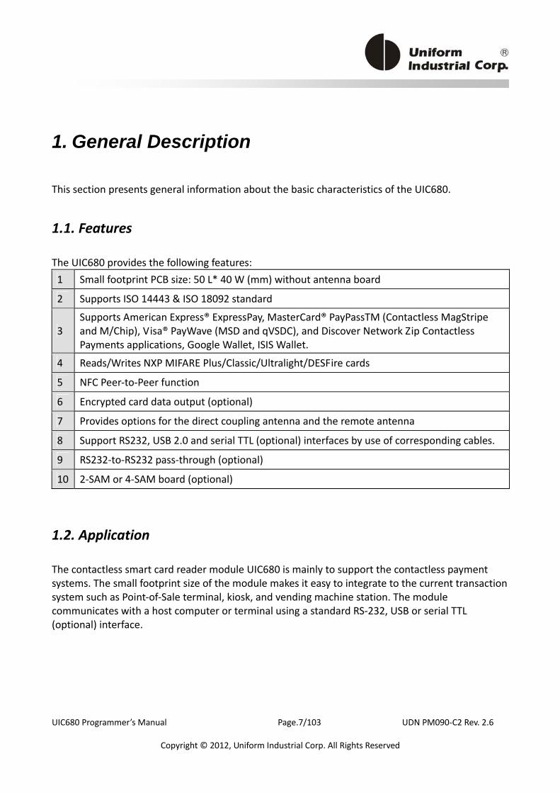
The UIC680 provides the following features: 1 Small footprint PCB size: 50 L* 40 W (mm) without antenna board
2 Supports ISO 14443 & ISO 18092 standard
3 Supports American Express® ExpressPay, MasterCard® PayPassTM (Contactless MagStripe and M/Chip), Visa® PayWave (MSD and qVSDC), and Discover Network Zip Contactless Payments applications, Google Wallet, ISIS Wallet.
4 Reads/Writes NXP MIFARE Plus/Classic/Ultralight/DESFire cards
5 NFC Peer‐to‐Peer function
6 Encrypted card data output (optional)
7 Provides options for the direct coupling antenna and the remote antenna
8 Support RS232, USB 2.0 and serial TTL (optional) interfaces by use of corresponding cables.
9 RS232‐to‐RS232 pass‐through (optional)
10 2‐SAM or 4‐SAM board (optional)
1.2. Application
The contactless smart card reader module UIC680 is mainly to support the contactless payment systems. The small footprint size of the module makes it easy to integrate to the current transaction system such as Point‐of‐Sale terminal, kiosk, and vending machine station. The module communicates with a host computer or terminal using a standard RS‐232, USB or serial TTL (optional) interface.
UIC680 Programmer’s Manual Page.8/103 UDN PM090‐C2 Rev. 2.6
Copyright © 2012, Uniform Industrial Corp. All Rights Reserved
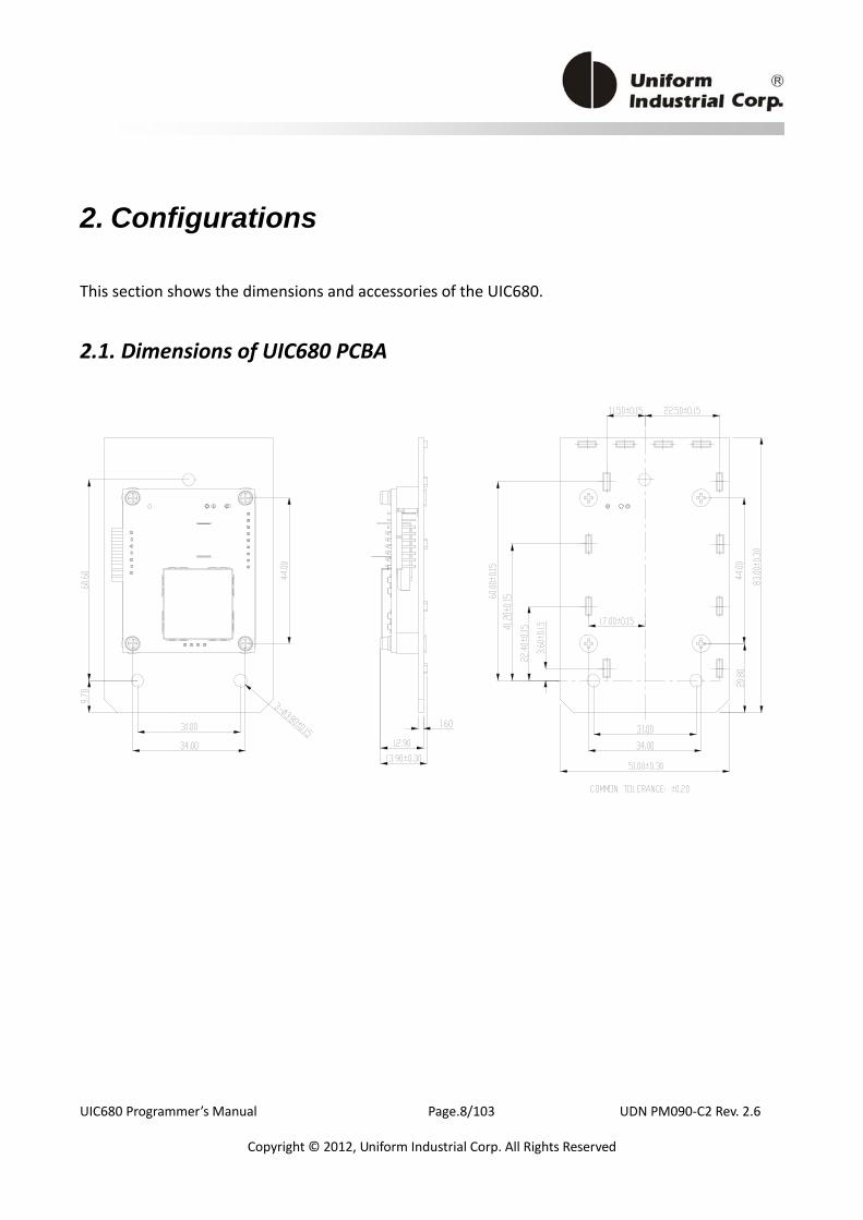
2. 5BConfigurations
This section shows the dimensions and accessories of the UIC680.
2.1. Dimensions of UIC680 PCBA
UIC680 Programmer’s Manual Page.9/103 UDN PM090‐C2 Rev. 2.6
Copyright © 2012, Uniform Industrial Corp. All Rights Reserved
3. 6BTechnical Specifications
3.1. Functional Specifications
Basic functions Contactless communication at 13.56MHz
4 LED indications for vertical or horizontal mount
Programmable audio buzzer
Real time clock /w 5 years battery life
Standards ISO 14443 type A and B compliant
ISO 18092 compliant
11BUInterfaces RS232 and USB2.0 interfaces by use of corresponding cables.
USB 2.0 compliant interface configurable to support USB HID Keyboard, or USB Virtual COM.
RS232 data output baud rate up to 115.2K BPS
RS232 pass through baud rate up to 115.2K BPS (optional)
TTL level for serial data output (optional)
Antennas Build‐in direct matching antenna
Remote 50 ohm matching antenna (optional)
13BUPayment applications American Express ExpressPay
Discover ZIP
MasterCard PayPass/MCHIP
Visa MSD/qVSDC
Google wallet
ISIS wallet
UIC680 Programmer’s Manual Page.10/103 UDN PM090‐C2 Rev. 2.6
Copyright © 2012, Uniform Industrial Corp. All Rights Reserved
MIFARE applications Read/Write of MIFARE Plus/Classic/Ultralight/DESFire cards
Support MIFARE higher baud rate up to 424KHz
Encrypted card data (AES or Triple DES) Encrypted card data output (optional) DUKPT key management with more than 2M keys (model
selectable)
Authentication with RSA 2048 bit key
Contact smart card Supports 2‐SAM or 4‐SAM board (optional)
3.2. Mechanical Specifications
Dimension Without antenna board Length: 50 mm Width: 40 mm
3.3. Electrical Specifications
Power Required 5VDC ± 5%
Power Consumption 330mA in idle mode; 430mA in operating mode
Communication Standard RS232 signal level
Compatible with USB 2.0 specification
TTL 5V signal level (optional)
Communication Signal Logic 1 = ‐3 volts to ‐15 volts or TTL level 5 volts
UIC680 Programmer’s Manual Page.11/103 UDN PM090‐C2 Rev. 2.6
Copyright © 2012, Uniform Industrial Corp. All Rights Reserved
(RS232) Logic 0 = +3 volts to +15 volts or TTL level 0 volt
3.4. Environmental Specifications
Temperature Operating: ‐20 to 70℃
Storage: ‐30 to 70℃
Extended Temperature Operating: ‐25 to 80℃
Storage: ‐30 to 85℃
(Optional Model – Conformal Coating and No Battery.)
Humidity Operating: 10 to 85% (non condensing)
Storage: 10 to 90% (non condensing)

UIC680 Programmer’s Manual Page.12/103 UDN PM090‐C2 Rev. 2.6
Copyright © 2012, Uniform Industrial Corp. All Rights Reserved
3.5. Pin Assignment
Interface J5 Pin Assignment
PCB‐J5 Direction Signal 1 GND 2 Serial data to host TXD_Out 3 Serial data from host RXD_In 4 VCC 5 USB data or Serial Pass‐thru (optional) USB D‐ or TXD2 (optional) 6 USB data or Serial Pass‐thru (optional) USB D+ or RXD2 (optional) 7 Shield
Direct Match Antenna Port J2A1 Pin Assignment Contact number Signal
1 RX 2 TX 3 GND 4 GND
Pin7 Pin 1
J5
UIC680 Programmer’s Manual Page.13/103 UDN PM090‐C2 Rev. 2.6
Copyright © 2012, Uniform Industrial Corp. All Rights Reserved
3.6. Communication
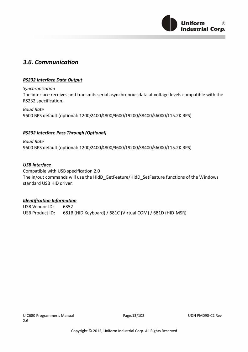
URS232 Interface Data Output
Synchronization The interface receives and transmits serial asynchronous data at voltage levels compatible with the RS232 specification.
Baud Rate 9600 BPS default (optional: 1200/2400/4800/9600/19200/38400/56000/115.2K BPS)
RS232 Interface Pass Through (Optional)
Baud Rate 9600 BPS default (optional: 1200/2400/4800/9600/19200/38400/56000/115.2K BPS)
USB Interface Compatible with USB specification 2.0 The in/out commands will use the HidD_GetFeature/HidD_SetFeature functions of the Windows standard USB HID driver.
Identification Information USB Vendor ID: 6352 USB Product ID: 681B (HID Keyboard) / 681C (Virtual COM) / 681D (HID‐MSR)

UIC680 Programmer’s Manual Page.14/103 UDN PM090‐C2 Rev. 2.6
Copyright © 2012, Uniform Industrial Corp. All Rights Reserved
4. 7BOperation
After power up the device, the first right vertical LED is turned on with one beep sound indicating that the reader is ready to operate. As factory default setting, UIC680 is set to Self‐Arm mode enabled. Under this mode, the reader will read and transmit payment cardF
1F data automatically. User needs to disable this mode in order to
send contactless card operation commands.
4.1. Reader Default Setting
Item Description EEPROM Default Value UART1 setting (Txd1/Rxd1) 9600‐8‐N‐1 Data pass through mode Disable UART2 setting (Txd1/Rxd2) 38400‐8‐N‐1 (optional) USB Interface USB HID Keyboard Buzzer Enable Protocol format Protocol 0 (USI0) Contactless Self‐Arm mode Enable Contactless smart card manual type (only available in host poll mode) Type A
Optional functions for the variant versionsF
2F
Google application Mifare First Administration command protect Enable Data Encryption Enable Crypto Algorithm TDES DUKPT Key Management Mode Auto rollover 1 Pre‐load encryption key (Customer specific or UIC default) Pre‐load Google Wallet merchant keys Yes (per merchant request)
1 Payment card – the card with MasterCard PayPass, VISA payWave, ExpressPay, or Discover Zip
application. 2 Please contact UIC support team for more detail information.

UIC680 Programmer’s Manual Page.15/103 UDN PM090‐C2 Rev. 2.6
Copyright © 2012, Uniform Industrial Corp. All Rights Reserved
4.2. Reader Configurations
4.2.1. Transmission Protocol
The user may select from three different protocols: Protocol 0, 1, and 2. Upon reset, the reader will send out the default power‐on character “:”, or any character specified by the configuration setting. Important: When the UIC680 is working in the USB interface, we need to add the header byte C2h and the 2‐byte data length before the command.
Protocol 0
In Protocol 0, all characters are transmitted and received using exactly the characters listed in Section 4. There are no headers and Block Check Characters (BCC). Protocol 0 presumes no transmission errors. If the host detects an error, it may request a retransmission. Example of Protocol 0, RS232 Interface
Example of Protocol 0, USB Interface
17BProtocol 1
In Protocol 1, all messages are preceded by the ASCII character <STX> and terminated with the ASCII character <ETX>, followed by a one byte <BCC>. <BCC> is an XOR of the 7 data bits, excluding parity, of each character in the entire message, including <STX>. Format: <STX><MESSAGE><ETX><BCC> Where STX=02Hex and ETX=03Hex.
Host Command Reader Response Comment
P Ready to read
^ Reader ACK
Host Command Reader Response Comment
<C2h><00h><01h>P Ready to read
<C2h><00h><01h>^ Reader ACK
UIC680 Programmer’s Manual Page.16/103 UDN PM090‐C2 Rev. 2.6
Copyright © 2012, Uniform Industrial Corp. All Rights Reserved
Example of Protocol 1, RS232 Interface
Example of Protocol 1, USB Interface
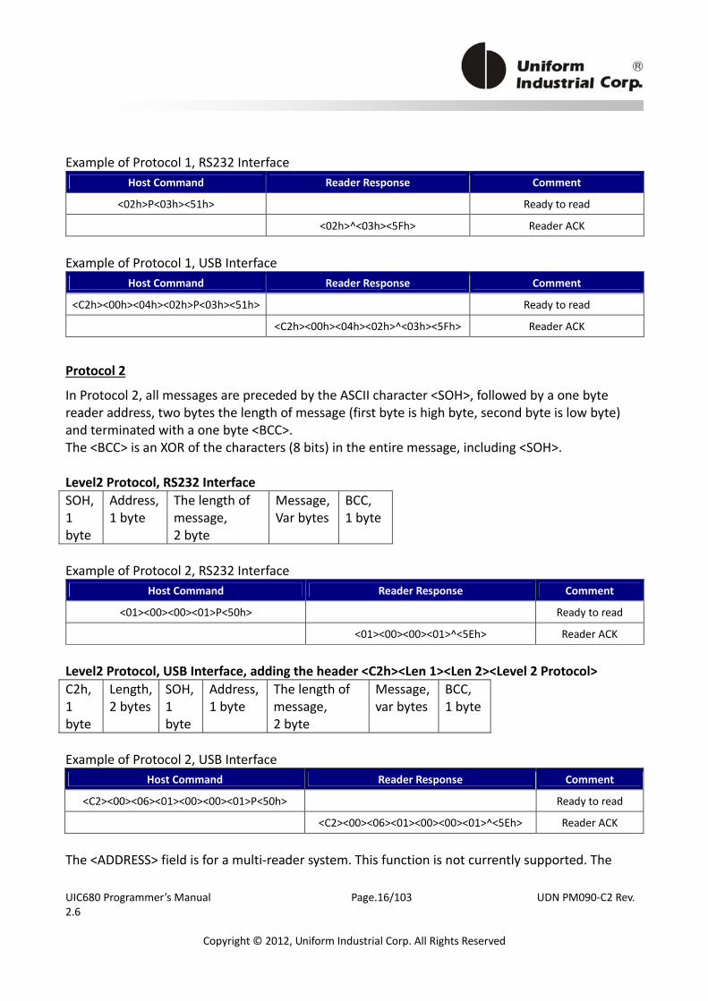
18BProtocol 2
In Protocol 2, all messages are preceded by the ASCII character <SOH>, followed by a one byte reader address, two bytes the length of message (first byte is high byte, second byte is low byte) and terminated with a one byte <BCC>. The <BCC> is an XOR of the characters (8 bits) in the entire message, including <SOH>. Level2 Protocol, RS232 Interface SOH, 1 byte
Address, 1 byte
The length of message, 2 byte
Message,Var bytes
BCC, 1 byte
Example of Protocol 2, RS232 Interface
Level2 Protocol, USB Interface, adding the header <C2h><Len 1><Len 2><Level 2 Protocol> C2h, 1 byte
Length, 2 bytes
SOH, 1 byte
Address, 1 byte
The length of message, 2 byte
Message, var bytes
BCC, 1 byte
Example of Protocol 2, USB Interface
The <ADDRESS> field is for a multi‐reader system. This function is not currently supported. The
Host Command Reader Response Comment
<02h>P<03h><51h> Ready to read
<02h>^<03h><5Fh> Reader ACK
Host Command Reader Response Comment
<C2h><00h><04h><02h>P<03h><51h> Ready to read
<C2h><00h><04h><02h>^<03h><5Fh> Reader ACK
Host Command Reader Response Comment
<01><00><00><01>P<50h> Ready to read
<01><00><00><01>^<5Eh> Reader ACK
Host Command Reader Response Comment
<C2><00><06><01><00><00><01>P<50h> Ready to read
<C2><00><06><01><00><00><01>^<5Eh> Reader ACK
UIC680 Programmer’s Manual Page.17/103 UDN PM090‐C2 Rev. 2.6
Copyright © 2012, Uniform Industrial Corp. All Rights Reserved
recommended value for this field is NULL (00Hex) but any value will work. For Protocols 1 and 2, if the reader detects an error in an incoming transmission, it will respond with a “Communications Error” message. If the host detects a transmission error, it may request a retransmission. Protocol 0 is the simplest protocol without adding the redundant data. In order to handle the properly communication, it enforces a 100mSec timeout between characters. In brief, the reader expects the incoming command is ready after 100 ms timeout. For the applications with the short latency requirement, please choose Protocol 1 or 2. The reader processes the incoming command right after received a complete packet. If the application requests to exchange the binary data, Protocol 2 is recommended.
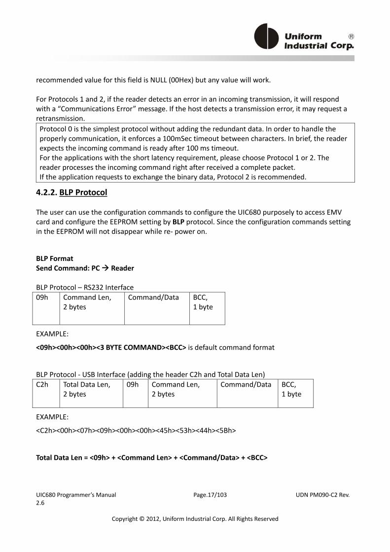
4.2.2. BLP Protocol
The user can use the configuration commands to configure the UIC680 purposely to access EMV card and configure the EEPROM setting by BLP protocol. Since the configuration commands setting in the EEPROM will not disappear while re‐ power on.
BLP Format Send Command: PC Reader BLP Protocol – RS232 Interface 09h Command Len,
2 bytes Command/Data BCC,
1 byte
EXAMPLE:
<09h><00h><00h><3 BYTE COMMAND><BCC> is default command format
BLP Protocol ‐ USB Interface (adding the header C2h and Total Data Len) C2h Total Data Len,
2 bytes 09h Command Len,
2 bytes Command/Data BCC,
1 byte
EXAMPLE:
<C2h><00h><07h><09h><00h><00h><45h><53h><44h><5Bh>
Total Data Len = <09h> + <Command Len> + <Command/Data> + <BCC>

UIC680 Programmer’s Manual Page.18/103 UDN PM090‐C2 Rev. 2.6
Copyright © 2012, Uniform Industrial Corp. All Rights Reserved
Command Len give the length of the command (first byte is high byte, second byte is low byte). If Command Len is 00h that indicates the command is 3 bytes
BCC = <09h> ⊕ <Command Len> ….<C⊕ ommand N>, BCC is the calculated the first byte to the last byte before BCC.
Note:
If Command Len is 00h or 03h, it indicates that 3‐byte commands come next.
If Command Len is 02h, it indicates that 2‐byte commands come next.
In BLP protocol, if the third command byte is <00h>, you can send only 2 bytes command (Command Len = 02h) and ignore the third command byte.
Response: Reader PC
Protocol of RS232 interface
^ (5Eh) – ACK: Acknowledges correct completion of most recent command.
! (21h) – Invalid Command: Command was received correctly, but is not a recognized.
DATA: No wrapped data.
Protocol of USB HID interface
<C2h><00h><01h><5Eh> – ACK: Acknowledges correct completion of most recent command.
<C2h><00h><01h><21h> – Invalid Command: Command was received correctly, but is not a recognized.
<C2h><Total Data Len>DATA: No wrapped data.

UIC680 Programmer’s Manual Page.19/103 UDN PM090‐C2 Rev. 2.6
Copyright © 2012, Uniform Industrial Corp. All Rights Reserved
4.2.3. Self – Arm Mode
The default reader configuration is in “Self‐Arm Mode”. This allows the payment cards (including PayPass Magnetic Stripe, VISA MSD, ExpressPay card and the general magnetic stripe credit cards) reading functions to run automatically, reporting the card data to the host without any instruction sent from the host. With the reader running In the Self‐Arm Mode, it can be configured to the “Host Polled Mode” by disabling the Self‐Arm Mode. The “Host Polled Mode” allows the card reading functions to be controlled by the relevant host commands.
19BCard Data Output for Different Types of Card and Reader Configurations
With the reader running in the Self‐Arm mode, depending on the configuration set in the reader and the type of card to be read, the reader will output different types of card information. The following table lists out the summary of it:
Reader Configuration
Mifare Card Support Type of Card
Disabled (MFxy = 10)F
3F Enabled (MFxy = 11)
Payment Card Track data Track data
Mifare Standard 1K N/A “M2”
Mifare Standard 4K N/A “M3”
Mifare Ultralight N/A “M1”
Mifare Ultralight C N/A “M1”
Mifare DESFire N/A “M4”
Mifare Plus N/A “M5”
20BCard Data Output in Self‐Arm and Host‐Polled modes
Sending card data under the Self‐Arm mode: Under the Self‐Arm mode, the card data output will not include the protocol envelope code. The user can insert the envelope code by utilizing the configuration commands-SE and TOF
4F.
3 Please refer to UIC680 Configuration Guide for the detail information. 4 Please refer to UIC680 Configuration Guide for the detail information.
UIC680 Programmer’s Manual Page.20/103 UDN PM090‐C2 Rev. 2.6
Copyright © 2012, Uniform Industrial Corp. All Rights Reserved
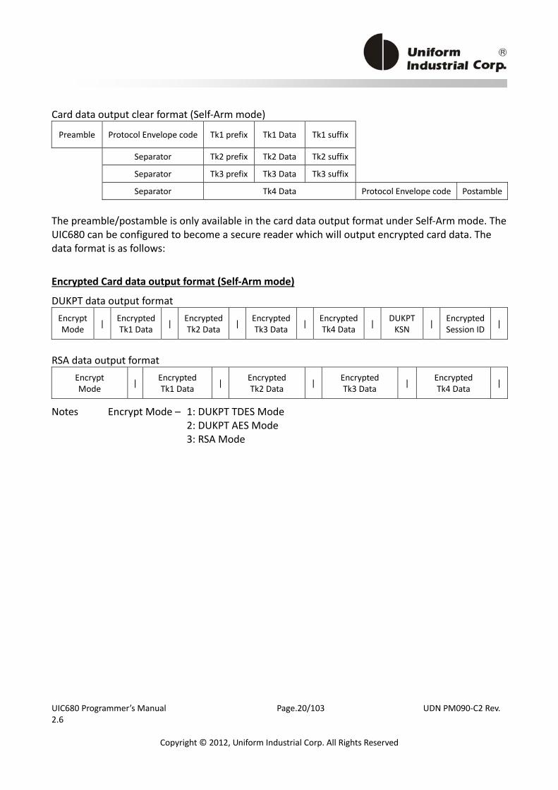
Card data output clear format (Self‐Arm mode)
Preamble Protocol Envelope code Tk1 prefix Tk1 Data Tk1 suffix
Separator Tk2 prefix Tk2 Data Tk2 suffix
Separator Tk3 prefix Tk3 Data Tk3 suffix
Separator Tk4 Data Protocol Envelope code Postamble
The preamble/postamble is only available in the card data output format under Self‐Arm mode. The UIC680 can be configured to become a secure reader which will output encrypted card data. The data format is as follows:
21BEncrypted Card data output format (Self‐Arm mode)
DUKPT data output format Encrypt Mode | Encrypted
Tk1 Data | Encrypted Tk2 Data | Encrypted
Tk3 Data | Encrypted Tk4 Data | DUKPT
KSN | EncryptedSession ID |
RSA data output format
Encrypt Mode | Encrypted
Tk1 Data | Encrypted Tk2 Data | Encrypted
Tk3 Data | Encrypted Tk4 Data |
Notes Encrypt Mode – 1: DUKPT TDES Mode 2: DUKPT AES Mode 3: RSA Mode
UIC680 Programmer’s Manual Page.21/103 UDN PM090‐C2 Rev. 2.6
Copyright © 2012, Uniform Industrial Corp. All Rights Reserved
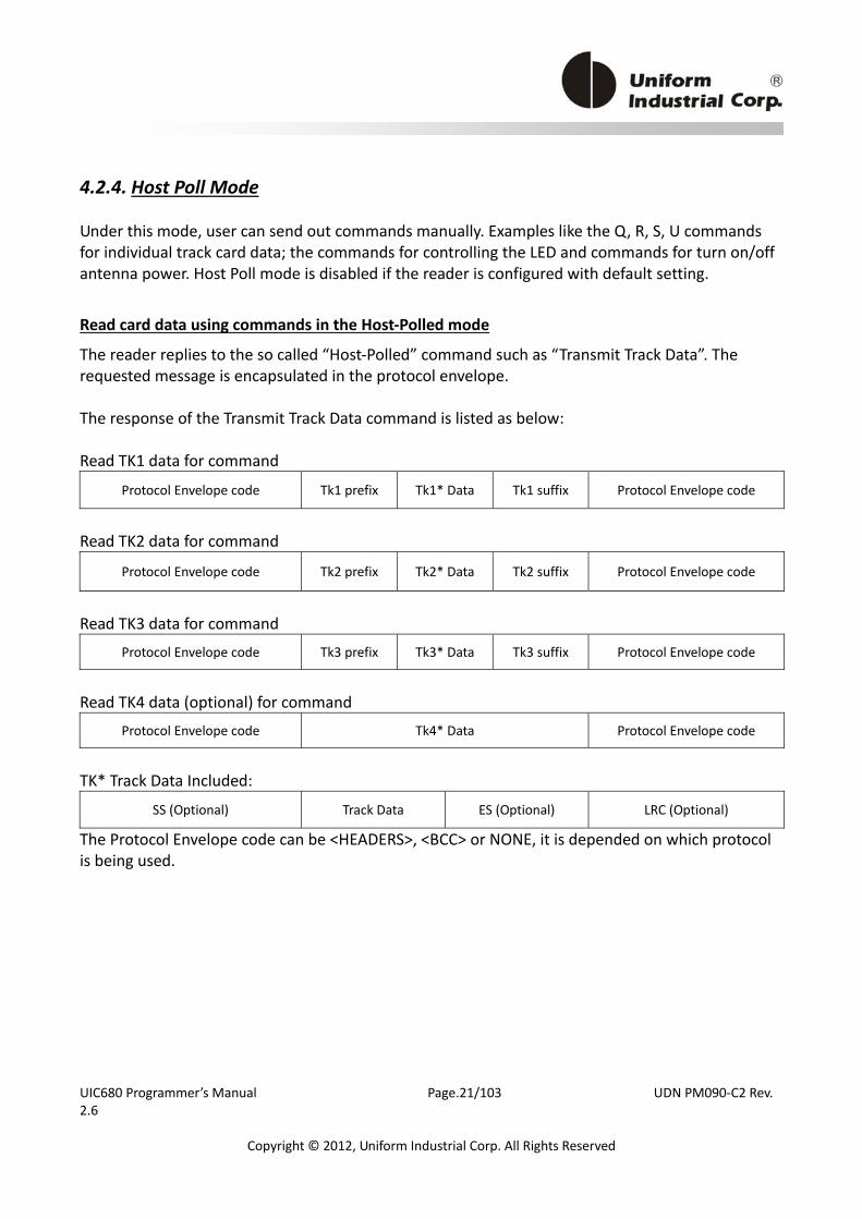
4.2.4. Host Poll Mode
Under this mode, user can send out commands manually. Examples like the Q, R, S, U commands for individual track card data; the commands for controlling the LED and commands for turn on/off antenna power. Host Poll mode is disabled if the reader is configured with default setting.
22BRead card data using commands in the Host‐Polled mode
The reader replies to the so called “Host‐Polled” command such as “Transmit Track Data”. The requested message is encapsulated in the protocol envelope. The response of the Transmit Track Data command is listed as below: Read TK1 data for command
Protocol Envelope code Tk1 prefix Tk1* Data Tk1 suffix Protocol Envelope code
Read TK2 data for command
Protocol Envelope code Tk2 prefix Tk2* Data Tk2 suffix Protocol Envelope code
Read TK3 data for command
Protocol Envelope code Tk3 prefix Tk3* Data Tk3 suffix Protocol Envelope code
Read TK4 data (optional) for command
Protocol Envelope code Tk4* Data Protocol Envelope code
TK* Track Data Included:
SS (Optional) Track Data ES (Optional) LRC (Optional)
The Protocol Envelope code can be <HEADERS>, <BCC> or NONE, it is depended on which protocol is being used.
UIC680 Programmer’s Manual Page.22/103 UDN PM090‐C2 Rev. 2.6
Copyright © 2012, Uniform Industrial Corp. All Rights Reserved
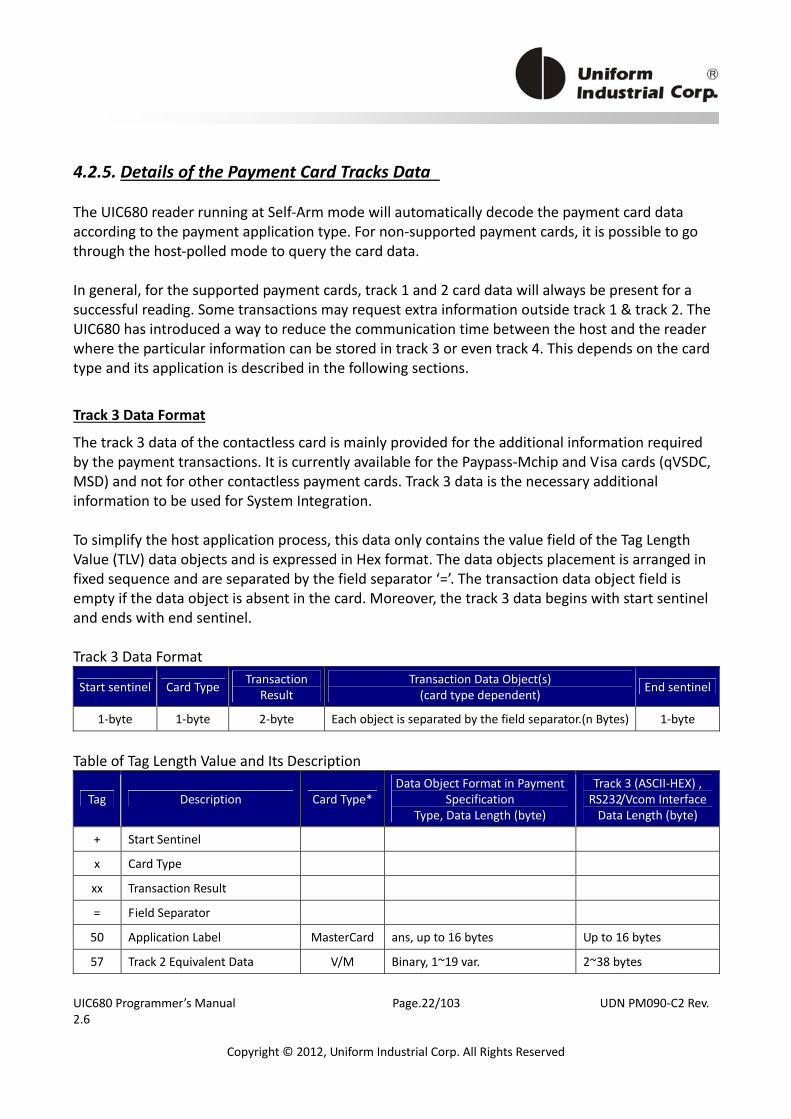
4.2.5. Details of the Payment Card Tracks Data
The UIC680 reader running at Self‐Arm mode will automatically decode the payment card data according to the payment application type. For non‐supported payment cards, it is possible to go through the host‐polled mode to query the card data. In general, for the supported payment cards, track 1 and 2 card data will always be present for a successful reading. Some transactions may request extra information outside track 1 & track 2. The UIC680 has introduced a way to reduce the communication time between the host and the reader where the particular information can be stored in track 3 or even track 4. This depends on the card type and its application is described in the following sections.
23BTrack 3 Data Format
The track 3 data of the contactless card is mainly provided for the additional information required by the payment transactions. It is currently available for the Paypass‐Mchip and Visa cards (qVSDC, MSD) and not for other contactless payment cards. Track 3 data is the necessary additional information to be used for System Integration. To simplify the host application process, this data only contains the value field of the Tag Length Value (TLV) data objects and is expressed in Hex format. The data objects placement is arranged in fixed sequence and are separated by the field separator ‘=’. The transaction data object field is empty if the data object is absent in the card. Moreover, the track 3 data begins with start sentinel and ends with end sentinel. Track 3 Data Format
Start sentinel Card Type Transaction Result
Transaction Data Object(s) (card type dependent) End sentinel
1‐byte 1‐byte 2‐byte Each object is separated by the field separator.(n Bytes) 1‐byte
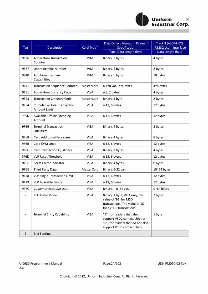
Table of Tag Length Value and Its Description
Tag Description Card Type*Data Object Format in Payment
Specification Type, Data Length (byte)
Track 3 (ASCII‐HEX) , RS232/Vcom Interface Data Length (byte)
+ Start Sentinel
x Card Type
xx Transaction Result
= Field Separator
50 Application Label MasterCard ans, up to 16 bytes Up to 16 bytes
57 Track 2 Equivalent Data V/M Binary, 1~19 var. 2~38 bytes

UIC680 Programmer’s Manual Page.23/103 UDN PM090‐C2 Rev. 2.6
Copyright © 2012, Uniform Industrial Corp. All Rights Reserved
Tag Description Card Type*Data Object Format in Payment
Specification Type, Data Length (byte)
Track 3 (ASCII‐HEX) , RS232/Vcom Interface Data Length (byte)
5A PAN V/M cn, 0~19 var, up to 10 byte. 0~20 bytes
5F20 Cardholder Name VISA ans 2~26, 2~26 bytes 2~26 bytes
5F24 Expiry Date V/M n 6 (YYMMDD), 3 bytes 6 bytes
5F2A Transaction Currency Code V/M Binary, 2 bytes 4 bytes
5F34 Application PAN Sequence Number
V/M n 2, 1 byte 2 bytes
82 Application Interchange Profile
V/M Binary, 2 bytes 4 bytes
84 Dedicated File Name MasterCard Binary, 5~16 var. 10~32 var
95 Terminal Verification Results V/M Binary, 5 bytes 10 bytes
9A Transaction Date V/M n 6 (YYMMDD), 3 bytes 6 bytes
9B Transaction Status Information
V/M Binary, 2 bytes 4 bytes
9C Transaction Type V/M n 2, 1 byte 2 bytes
9F02 Amount, Authorized (Numeric)
V/M n 12, 6 bytes 12 bytes
9F03 Amount, Other (Numeric) V/M n 12, 6 bytes 12 bytes
9F09 Terminal Application Version Number
V/M Binary, 2 bytes 4 bytes
9F10 Issuer Application Data V/M Binary, var. up to 32 bytes var. up to 64 bytes
9F11 Issuer Code Table Index MasterCard n 2, 1 bytes 4 bytes
9F12 Application Preferred Name MasterCard ans, up to 16 bytes Up to 16 bytes
9F16 Merchant ID V/M ans, 15 bytes 30 bytes
9F17 Personal Identification Number (PIN) Try Counter
VISA Binary, 1 byte 2 bytes
9F1A Terminal Country Code V/M Binary, 2 bytes 4 bytes
9F1E Interface Device Serial Number (IFD)
V/M an, 8 bytes 16 bytes
9F26 Application Cryptogram V/M Binary, 8 byte 16 bytes
9F27 Cryptogram Information Data MasterCard Binary, 1 byte 2 bytes
9F33 Terminal Capabilities V/M Binary, 3 bytes 6 bytes
9F34 Cardholder Verification Method Results
MasterCard Binary, 3 bytes 6 bytes
9F35 Terminal Type V/M n 2, 1 byte 2 bytes
UIC680 Programmer’s Manual Page.24/103 UDN PM090‐C2 Rev. 2.6
Copyright © 2012, Uniform Industrial Corp. All Rights Reserved
Tag Description Card Type*Data Object Format in Payment
Specification Type, Data Length (byte)
Track 3 (ASCII‐HEX) , RS232/Vcom Interface Data Length (byte)
9F36 Application Transaction Counter
V/M Binary, 2 bytes 4 bytes
9F37 Unpredictable Number V/M Binary, 4 bytes 8 bytes
9F40 Additional Terminal Capabilities
V/M Binary, 5 bytes 10 bytes
9F41 Transaction Sequence Counter MasterCard n 4~8 var., 2~4 bytes 4~8 bytes
9F51 Application Currency Code VISA n 3, 2 bytes 4 bytes
9F53 Transaction Category Code MasterCard Binary, 1 byte 2 bytes
9F54 Cumulative Total Transaction Amount Limit
VISA n 12, 6 bytes 12 bytes
9F5D Available Offline Spending Amount
VISA n 12, 6 bytes 12 bytes
9F66 Terminal Transaction Qualifiers
VISA Binary, 4 bytes 8 bytes
9F68 Card Additional Processes VISA Binary, 4 bytes 8 bytes
9F6B Card CVM Limit VISA n 12, 6 bytes 12 bytes
9F6C Card Transaction Qualifiers VISA Binary, 2 bytes 4 bytes
9F6D VLP Reset Threshold VISA n 12, 6 bytes 12 bytes
9F6E Form Factor Indicator VISA Binary, 4 bytes 8 bytes
9F6E Third Party Data MasterCard Binary, 5‐32 var. 10~64 bytes
9F78 VLP Single Transaction Limit VISA n 12, 6 bytes 12 bytes
9F79 VLP Available Funds VISA n 12, 6 bytes 12 bytes
9F7C Customer Exclusive Data VISA Binary, 0~32 var. 0~64 bytes
‐ POS Entry Mode VISA Binary, 1 byte, VISA only, the value of ‘91’ for MSD transactions. The value of ‘07’ for qVSDC transactions
2 bytes
‐ Terminal Entry Capability VISA “5” (for readers that also support VSDC contact chip) or “8” (for readers that do not also support VSDC contact chip).
1 byte
? End Sentinel
UIC680 Programmer’s Manual Page.25/103 UDN PM090‐C2 Rev. 2.6
Copyright © 2012, Uniform Industrial Corp. All Rights Reserved
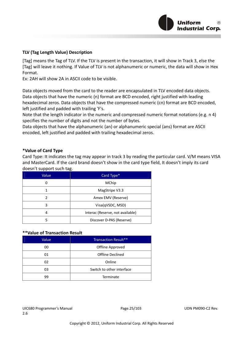
TLV (Tag Length Value) Description
[Tag] means the Tag of TLV. If the TLV is present in the transaction, it will show in Track 3, else the [Tag] will leave it nothing. If Value of TLV is not alphanumeric or numeric, the data will show in Hex Format. Ex: 2AH will show 2A in ASCII code to be visible. Data objects moved from the card to the reader are encapsulated in TLV encoded data objects. Data objects that have the numeric (n) format are BCD encoded, right justified with leading hexadecimal zeros. Data objects that have the compressed numeric (cn) format are BCD encoded, left justified and padded with trailing 'F's. Note that the length indicator in the numeric and compressed numeric format notations (e.g. n 4) specifies the number of digits and not the number of bytes. Data objects that have the alphanumeric (an) or alphanumeric special (ans) format are ASCII encoded, left justified and padded with trailing hexadecimal zeros. *Value of Card Type Card Type: It indicates the tag may appear in track 3 by reading the particular card. V/M means VISA and MasterCard. If the card brand doesn’t show in the card type field, It doesn’t imply its card doesn’t support such tag.
Value Card Type*
0 MChip
1 MagStripe V3.3
2 Amex EMV (Reserve)
3 Visa(qVSDC, MSD)
4 Interac (Reserve, not available)
5 Discover D‐PAS (Reserve)
**Value of Transaction Result
Value Transaction Result**
00 Offline Approved
01 Offline Declined
02 Online
03 Switch to other interface
99 Terminate
UIC680 Programmer’s Manual Page.26/103 UDN PM090‐C2 Rev. 2.6
Copyright © 2012, Uniform Industrial Corp. All Rights Reserved
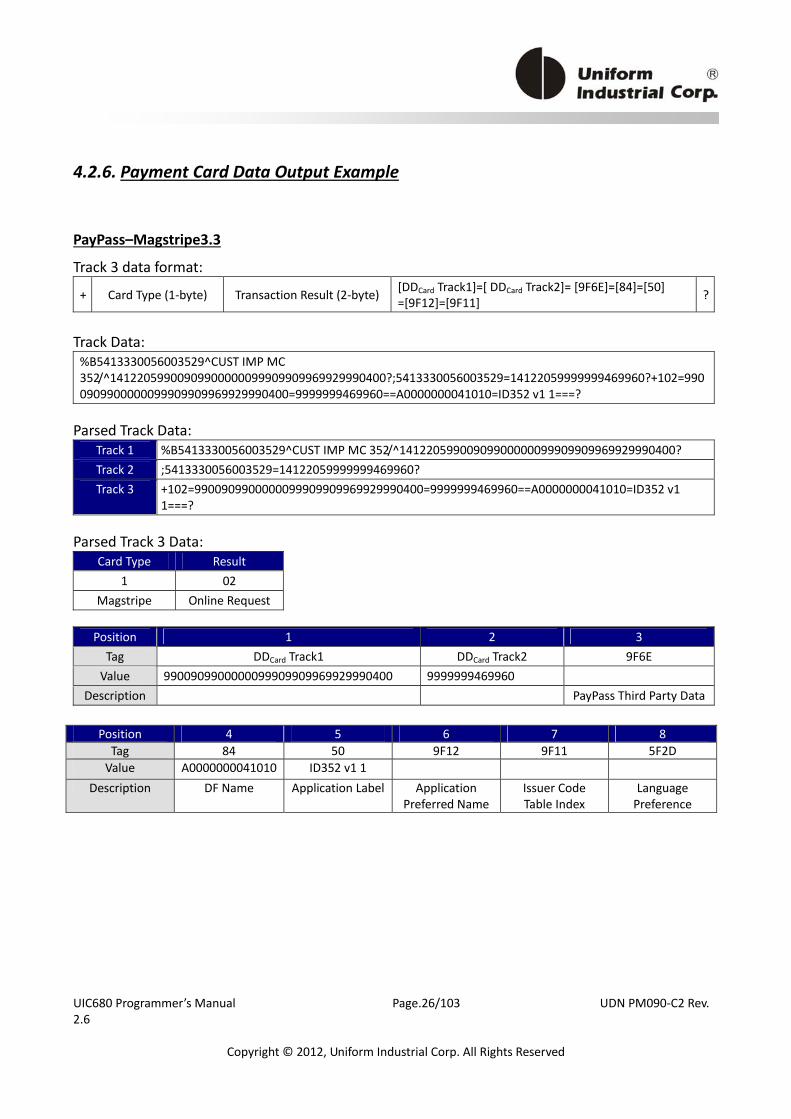
4.2.6. Payment Card Data Output Example
PayPass–Magstripe3.3
Track 3 data format:
+ Card Type (1‐byte) Transaction Result (2‐byte) [DDCard Track1]=[ DDCard Track2]= [9F6E]=[84]=[50] =[9F12]=[9F11] ?
Track Data: %B5413330056003529^CUST IMP MC 352/^14122059900909900000099909909969929990400?;5413330056003529=14122059999999469960?+102=9900909900000099909909969929990400=9999999469960==A0000000041010=ID352 v1 1===?
Parsed Track Data:
Track 1 %B5413330056003529^CUST IMP MC 352/^14122059900909900000099909909969929990400? Track 2 ;5413330056003529=14122059999999469960? Track 3 +102=9900909900000099909909969929990400=9999999469960==A0000000041010=ID352 v1
1===? Parsed Track 3 Data:
Card Type Result 1 02
Magstripe Online Request
Position 1 2 3 Tag DDCard Track1 DDCard Track2 9F6E Value 9900909900000099909909969929990400 9999999469960
Description PayPass Third Party Data
Position 4 5 6 7 8 Tag 84 50 9F12 9F11 5F2D Value A0000000041010 ID352 v1 1
Description DF Name Application Label Application Preferred Name
Issuer Code Table Index
Language Preference
UIC680 Programmer’s Manual Page.27/103 UDN PM090‐C2 Rev. 2.6
Copyright © 2012, Uniform Industrial Corp. All Rights Reserved
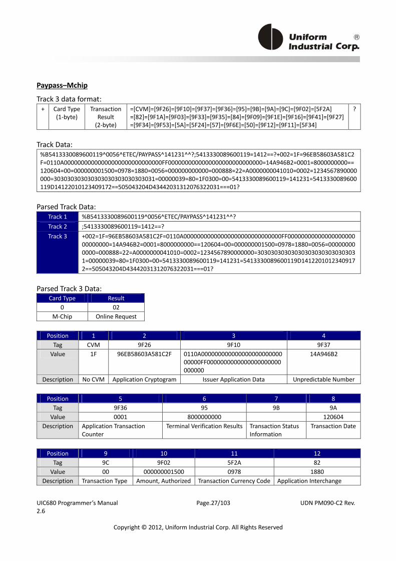
Paypass–Mchip
Track 3 data format: + Card Type
(1‐byte) Transaction
Result (2‐byte)
=[CVM]=[9F26]=[9F10]=[9F37]=[9F36]=[95]=[9B]=[9A]=[9C]=[9F02]=[5F2A] =[82]=[9F1A]=[9F03]=[9F33]=[9F35]=[84]=[9F09]=[9F1E]=[9F16]=[9F41]=[9F27]=[9F34]=[9F53]=[5A]=[5F24]=[57]=[9F6E]=[50]=[9F12]=[9F11]=[5F34]
?
Track Data: %B5413330089600119^0056^ETEC/PAYPASS^141231^^?;5413330089600119=1412==?+002=1F=96EB58603A581C2F=0110A00000000000000000000000000000FF0000000000000000000000000000=14A946B2=0001=8000000000==120604=00=000000001500=0978=1880=0056=000000000000=000888=22=A0000000041010=0002=1234567890000000=303030303030303030303030303031=00000039=80=1F0300=00=5413330089600119=141231=5413330089600119D14122010123409172==505043204D43442031312076322031===01?
Parsed Track Data:
Track 1 %B5413330089600119^0056^ETEC/PAYPASS^141231^^? Track 2 ;5413330089600119=1412==? Track 3 +002=1F=96EB58603A581C2F=0110A00000000000000000000000000000FF00000000000000000000
00000000=14A946B2=0001=8000000000==120604=00=000000001500=0978=1880=0056=000000000000=000888=22=A0000000041010=0002=1234567890000000=303030303030303030303030303031=00000039=80=1F0300=00=5413330089600119=141231=5413330089600119D14122010123409172==505043204D43442031312076322031===01?
Parsed Track 3 Data:
Card Type Result 0 02
M‐Chip Online Request
Position 1 2 3 4 Tag CVM 9F26 9F10 9F37 Value 1F 96EB58603A581C2F 0110A000000000000000000000000
00000FF0000000000000000000000000000
14A946B2
Description No CVM Application Cryptogram Issuer Application Data Unpredictable Number
Position 5 6 7 8 Tag 9F36 95 9B 9A Value 0001 8000000000 120604
Description Application Transaction Counter
Terminal Verification Results Transaction Status Information
Transaction Date
Position 9 10 11 12 Tag 9C 9F02 5F2A 82 Value 00 000000001500 0978 1880
Description Transaction Type Amount, Authorized Transaction Currency Code Application Interchange
UIC680 Programmer’s Manual Page.28/103 UDN PM090‐C2 Rev. 2.6
Copyright © 2012, Uniform Industrial Corp. All Rights Reserved
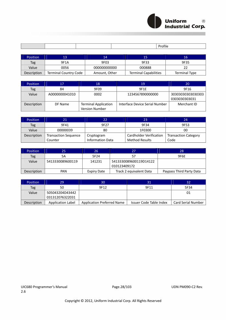
Profile
Position 13 14 15 16 Tag 9F1A 9F03 9F33 9F35 Value 0056 000000000000 000888 22
Description Terminal Country Code Amount, Other Terminal Capabilities Terminal Type
Position 17 18 19 20 Tag 84 9F09 9F1E 9F16 Value A0000000041010 0002 1234567890000000 30303030303030303
0303030303031 Description DF Name Terminal Application
Version Number Interface Device Serial Number Merchant ID
Position 21 22 23 24 Tag 9F41 9F27 9F34 9F53 Value 00000039 80 1F0300 00
Description Transaction Sequence Counter
Cryptogram Information Data
Cardholder Verification Method Results
Transaction Category Code
Position 25 26 27 28 Tag 5A 5F24 57 9F6E Value 5413330089600119 141231 5413330089600119D14122
010123409172
Description PAN Expiry Date Track 2 equivalent Data Paypass Third Party Data
Position 29 30 31 32 Tag 50 9F12 9F11 5F34 Value 505043204D43442
031312076322031 01
Description Application Label Application Preferred Name Issuer Code Table Index Card Serial Number

UIC680 Programmer’s Manual Page.29/103 UDN PM090‐C2 Rev. 2.6
Copyright © 2012, Uniform Industrial Corp. All Rights Reserved
Visa (qVSDC, MSD)
Track 3 data format: + Card Type
(1‐byte) Transaction
Result (2‐byte)
=[9F26]=[9F10]=[9F37]=[9F36]=[9F66]=[95]=[9B]=[9A]=[9F02]=[5F2A]=[82] =[9F1A]=[9F03]=[9F33]=[9F35]=[9F09]=[9F1E]=[9F16]=[5F34]=[9F40]=[9F6E] =[9F7C]=[57]=[5A]=[5F20]=[5F24]=[9C]=[9F5D]=[9F68]=[9F6C]=[9F6B]=[9F51] =[9F17]=[9F78]=[9F79]=[9F6D]=[9F54]=[POS Entry Mode]=[Terminal Enter Capability]
?
Track Data: %B4761739001010010^ /^201212000123100399030000?;4761739001010010=20121200012339900031?+300=AABBCCDDEEFF1122=06011103900000=94018C92=0003=A0804000=0000000000==120604=000000000100=0840=2000=0840=000000000000=000888=22=0000=1234567890000000=303030303030303030303030303031=01=6000000001===4761739001010010D20121200012339900031F=4761739001010010==201231=00=000000010000==3000========07=08=40?
Parsed Track Data:
Track 1 %B4761739001010010^ /^201212000123100399030000? Track 2 ;4761739001010010=20121200012339900031? Track 3 +302=AABBCCDDEEFF1122=06011103900000=94018C92=0003=A0804000=0000000000==120604=0
00000000100=0840=2000=0840=000000000000=000888=22=0000=1234567890000000=303030303030303030303030303031=01=6000000001===4761739001010010D20121200012339900031F=4761739001010010==201231=00=000000010000==3000========07=08?
Parsed Track 3 Data:
Card Type Result 3 02
VISA Online Request
Position 1 2 3 4 Tag 9F26 9F10 9F37 9F36 Value AABBCCDDEEFF1122 06011103900000 94018C92 0003
Description Application Cryptogram
Issuer Application Data Unpredictable Number Application Transaction Counter
Position 5 6 7 8 Tag 9F66 95 9B 9A Value A0804000 0000000000 120604
Description Terminal Transaction Qualifiers
Terminal Verification Results
Transaction Status Information
Transaction Date
Position 9 10 11 12 Tag 9F02 5F2A 82 9F1A Value 000000000100 0840 2000 0840
Description Amount, Authorized Transaction Currency Code Application Interchange Profile
Terminal Country Code

UIC680 Programmer’s Manual Page.30/103 UDN PM090‐C2 Rev. 2.6
Copyright © 2012, Uniform Industrial Corp. All Rights Reserved
Position 13 14 15 16 Tag 9F03 9F33 9F35 9F09 Value 000000000000 000888 22 0000
Description Amount, Other Terminal Capabilities Terminal Type Application Version Number
Position 17 18 19 20 Tag 9F1E 9F16 5F34 9F40 Value 1234567890000000 30303030303030303030
3030303031 01 6000000001
Description Interface Device Serial Number
Merchant ID Application PAN Sequence Number
Additional Terminal Capabilities
Position 21 22 23 24 Tag 9F6E 9F7C 57 5A Value 4761739001010010D201
21200012339900031F 4761739001010010
Description Form Factor Indicator Customer Exclusive Data
Track 2 Equivalent Data PAN
Position 25 26 27 28 Tag 5F20 5F24 9C 9F5D Value 201231 00 000000010000
Description Cardholder Name Expiry Date Transaction Type Available Offline Spending Amount
Position 29 30 31 32 Tag 9F68 9F6C 9F6B 9F51 Value 3000
Description Card Additional Processes
Card Transaction Qualifiers
Card CVM Limit Application Currency Code
Position 33 34 35 36 Tag 9F17 9F78 9F79 9F6D Value
Description PIN Try Counter VLP Single Transaction Limit VLP Available Funds VLP Reset Threshold
Position 37 38 39 Tag 9F54 POS Entry Mode Terminal Enter CapabilityValue 07 08
Description Cumulative Total Transaction Amount Limit qVSDC transaction Always set to 8
Track 4 Data Format
The track 4 data of the contactless card is for the additional data or other payment card scheme.
UIC680 Programmer’s Manual Page.31/103 UDN PM090‐C2 Rev. 2.6
Copyright © 2012, Uniform Industrial Corp. All Rights Reserved
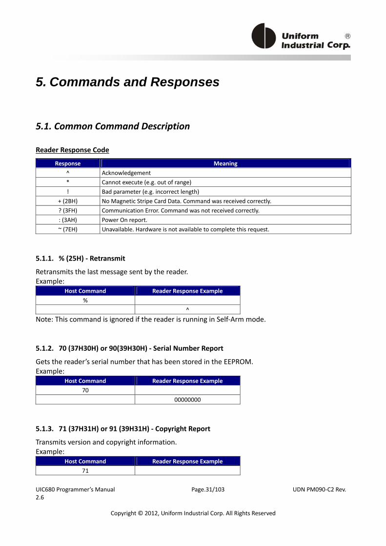
5. Commands and Responses
5.1. Common Command Description
Reader Response Code
Response Meaning ^ Acknowledgement * Cannot execute (e.g. out of range) ! Bad parameter (e.g. incorrect length)
+ (2BH) No Magnetic Stripe Card Data. Command was received correctly. ? (3FH) Communication Error. Command was not received correctly. : (3AH) Power On report. ~ (7EH) Unavailable. Hardware is not available to complete this request.
5.1.1. % (25H) ‐ Retransmit
Retransmits the last message sent by the reader. Example:
Host Command Reader Response Example % ^
Note: This command is ignored if the reader is running in Self‐Arm mode.
5.1.2. 70 (37H30H) or 90(39H30H) ‐ Serial Number Report
Gets the reader’s serial number that has been stored in the EEPROM. Example:
Host Command Reader Response Example 70 00000000
5.1.3. 71 (37H31H) or 91 (39H31H) ‐ Copyright Report Transmits version and copyright information. Example:
Host Command Reader Response Example 71
UIC680 Programmer’s Manual Page.32/103 UDN PM090‐C2 Rev. 2.6
Copyright © 2012, Uniform Industrial Corp. All Rights Reserved
121106,UIC 68TP961P:V1.P This command is sent if the user wants to know the version, model and copyright of the currently loaded UIC680 firmware. The response is an ASCII string giving the firmware date (yymmdd), reader type and the firmware version number, followed by the firmware copyright statement. The firmware copyright statement is absent in OEM version.
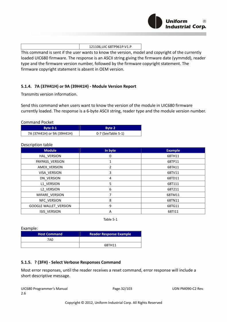
5.1.4. 7A (37H41H) or 9A (39H41H) ‐ Module Version Report
Transmits version information. Send this command when users want to know the version of the module in UIC680 firmware currently loaded. The response is a 6‐byte ASCII string, reader type and the module version number. Command Pocket
Byte 0‐1 Byte 2 7A (37H41H) or 9A (39H41H) 0‐7 (SeeTable 5‐1)
Description table
Module In byte Example HAL_VERSION 0 68TH11
PAYPASS_VERSION 1 68TP11 AMEX_VERSION 2 68TA11 VISA_VERSION 3 68TV11 DN_VERSION 4 68TD11 L1_VERSION 5 68T111 L2_VERSION 6 68T211
MIFARE_VERSION 7 68TM11 NFC_VERSION 8 68TN11
GOOGLE WALLET_VERSION 9 68TG11 ISIS_VERSION A 68TI11
Example:
Host Command Reader Response Example 7A0 68TH11
5.1.5. ? (3FH) ‐ Select Verbose Responses Command
Most error responses, until the reader receives a reset command, error response will include a short descriptive message.
Table 5‐1
UIC680 Programmer’s Manual Page.33/103 UDN PM090‐C2 Rev. 2.6
Copyright © 2012, Uniform Industrial Corp. All Rights Reserved
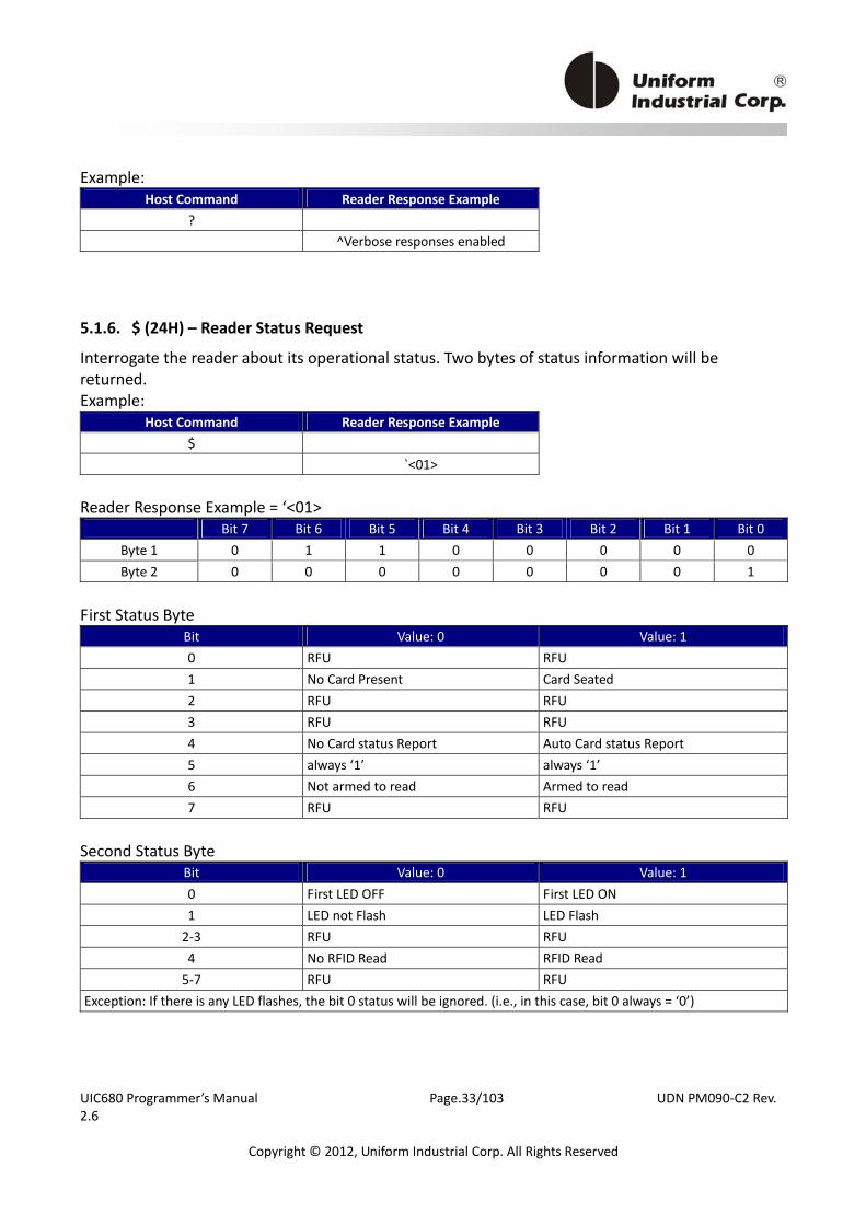
Example: Host Command Reader Response Example
? ^Verbose responses enabled
5.1.6. $ (24H) – Reader Status Request Interrogate the reader about its operational status. Two bytes of status information will be returned. Example:
Host Command Reader Response Example $ `<01>
Reader Response Example = ‘<01>
Bit 7 Bit 6 Bit 5 Bit 4 Bit 3 Bit 2 Bit 1 Bit 0 Byte 1 0 1 1 0 0 0 0 0 Byte 2 0 0 0 0 0 0 0 1
First Status Byte
Bit Value: 0 Value: 1 0 RFU RFU 1 No Card Present Card Seated 2 RFU RFU 3 RFU RFU 4 No Card status Report Auto Card status Report 5 always ‘1’ always ‘1’ 6 Not armed to read Armed to read 7 RFU RFU
Second Status Byte
Bit Value: 0 Value: 1 0 First LED OFF First LED ON 1 LED not Flash LED Flash 2‐3 RFU RFU 4 No RFID Read RFID Read 5‐7 RFU RFU
Exception: If there is any LED flashes, the bit 0 status will be ignored. (i.e., in this case, bit 0 always = ‘0’)
UIC680 Programmer’s Manual Page.34/103 UDN PM090‐C2 Rev. 2.6
Copyright © 2012, Uniform Industrial Corp. All Rights Reserved
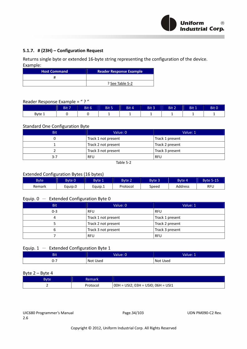
5.1.7. # (23H) – Configuration Request Returns single byte or extended 16‐byte string representing the configuration of the device. Example:
Host Command Reader Response Example # ? See Table 5‐2
Reader Response Example = “ ? ”
Bit 7 Bit 6 Bit 5 Bit 4 Bit 3 Bit 2 Bit 1 Bit 0 Byte 1 0 0 1 1 1 1 1 1
Standard One Configuration Byte
Bit Value: 0 Value: 1 0 Track 1 not present Track 1 present 1 Track 2 not present Track 2 present 2 Track 3 not present Track 3 present 3‐7 RFU RFU
Table 5‐2 Extended Configuration Bytes (16 bytes)
Byte Byte 0 Byte 1 Byte 2 Byte 3 Byte 4 Byte 5‐15 Remark Equip.0 Equip.1 Protocol Speed Address RFU
Equip. 0 - Extended Configuration Byte 0
Bit Value: 0 Value: 1 0‐3 RFU RFU 4 Track 1 not present Track 1 present 5 Track 2 not present Track 2 present 6 Track 3 not present Track 3 present 7 RFU RFU
Equip. 1 - Extended Configuration Byte 1
Bit Value: 0 Value: 1 0‐7 Not Used Not Used
Byte 2 – Byte 4
Byte Remark 2 Protocol 00H = USI2; 03H = USI0; 06H = USI1

UIC680 Programmer’s Manual Page.35/103 UDN PM090‐C2 Rev. 2.6
Copyright © 2012, Uniform Industrial Corp. All Rights Reserved
3 Speed 00H=1200, 01H=2400, 02H=4800, 03H=9600, 04H=19.2k, 05H=38.4k, 06H=56k, 07H=115.2k bps
4 Address Always 00H.
By using the configuration setting command, users can select standard or extended format. Extend command usage refer to UIC680 Configuration Guide.
5.1.8. <CAN> (18H) – Clear Data Buffer Clears read data buffers. Example:
Host Command Reader Response Example <18>
^
5.1.9. <DC2> (12H) – RS232 pass through enable (optional) Enable RS232 data Pass through (PT) function temporarily. The command characters are followed by an ASCII ‘P’ to enable the RS232 pass through function. It is only valid in RS232 model. Example:
Host Command Reader Response Example <12>P
^ Note: Once the pass through mode is enabled, UIC680 passes all data between COM1 and COM2 and do nothing. Power cycling (if the default of PT is disable) or send the string ‘<DC2>P<DC2>a<DC2>s<DC2>S’ brings UIC680 back to normal operation. Before sending this command, user must assure the PT function is desired.
5.1.10. <7FH> – Warm Reset
It aborts all current actions and causes the device to execute all initialization functions. The device will respond as if in a "power up" cycle; by default it returns a ‘:’ (3AH). This operation will take at least 3 seconds to complete. Example:
Host Command Reader Response Example

UIC680 Programmer’s Manual Page.36/103 UDN PM090‐C2 Rev. 2.6
Copyright © 2012, Uniform Industrial Corp. All Rights Reserved
<7F> ^
5.1.11. 5 (35H) – Set RTC Time
This command is used to set and read device’s RTC Time. Command Pocket
Byte 0 Byte 1 Byte 2 Byte 3 Byte 4 Byte 5 Byte 6 5 CMD Date or Time
CMD Description [CMD, 1 byte] (ASCII – Hex value) Description
1 (or 31h) Read Date 2 (or 32h) Read Time 3 (or 33h) RFU 4 (or 34h) Set Date 5 (or 35h) Set Time
51 (35H31H) ‐ Read Date Response data Pocket:
Byte 0 – Byte 1 Byte 2 Byte 3 Byte 4
Year Month Date Week <20*><12> <12> <06> <04>
*The year <20> can be interpreted as space character. 01h=Monday, 02h=Tuesday, …
07h=Sunday Note: BCD format from 010 (0000BCD = 0h) to 910 (1001BCD = 9h) Example:
Host Command Reader Response Example 51 <20*><12><12><06><04>
52 (35H32H) ‐ Read Time Response data Pocket:
Byte 0 – Byte 1 Byte 2 Byte 3 Byte 4
Hour Min Second Millisecond <16> <30> <00> <04><90>
Note: BCD format from 010 (0000BCD = 0h) to 910 (1001BCD = 9h) Example:
UIC680 Programmer’s Manual Page.37/103 UDN PM090‐C2 Rev. 2.6
Copyright © 2012, Uniform Industrial Corp. All Rights Reserved
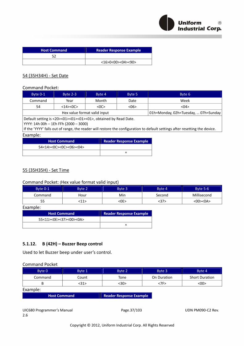
Host Command Reader Response Example 52 <16>0<00><04><90>
54 (35H34H) ‐ Set Date Command Pocket:
Byte 0‐1 Byte 2‐3 Byte 4 Byte 5 Byte 6
Command Year Month Date Week 54 <14><0C> <0C> <06> <04>
Hex value format valid input 01h=Monday, 02h=Tuesday, … 07h=SundayDefault setting is <20><01><01><01><01>, obtained by Read Date. YYYY: 14h 00h – 1Eh FFh (2000 – 3000) If the ‘YYYY’ falls out of range, the reader will restore the configuration to default settings after resetting the device.
Example: Host Command Reader Response Example
54<14><0C><0C><06><04> ^
55 (35H35H) ‐ Set Time Command Pocket: (Hex value format valid input)
Byte 0‐1 Byte 2 Byte 3 Byte 4 Byte 5‐6
Command Hour Min Second Millisecond 55 <11> <0E> <37> <00><0A>
Example: Host Command Reader Response Example
55<11><0E><37><00><0A> ^
5.1.12. B (42H) – Buzzer Beep control
Used to let Buzzer beep under user’s control. Command Pocket
Byte 0 Byte 1 Byte 2 Byte 3 Byte 4
Command Count Tone On Duration Short Duration B <31> <30> <7F> <00>
Example: Host Command Reader Response Example
UIC680 Programmer’s Manual Page.38/103 UDN PM090‐C2 Rev. 2.6
Copyright © 2012, Uniform Industrial Corp. All Rights Reserved
B<31><30><7F><00> ^
Command Type
Field Description 0 (30h, ASCII Hex) – long beep **Important: Once ‘B0’ command starts beeping, NO command can STOP it–unless users send a “Reset” command to stop it.
Count
1~9, A~F(31h~39h 41h~46h, ASCII Hex) – 1~15 short beeps Tone For adjus ng the frequency level, 00h~FFh(high → low).
On Duration The duration of a beep; time unit is 10ms, 00h means 10ms, FFh means 2560ms. Short Duration The interval between 2 beeps in unit of 10 milliseconds; 00h means 10ms, FFh means 2560ms.
Note: If Type parameter is omitted, reader will treat it as the ONE SHORT Beep command.
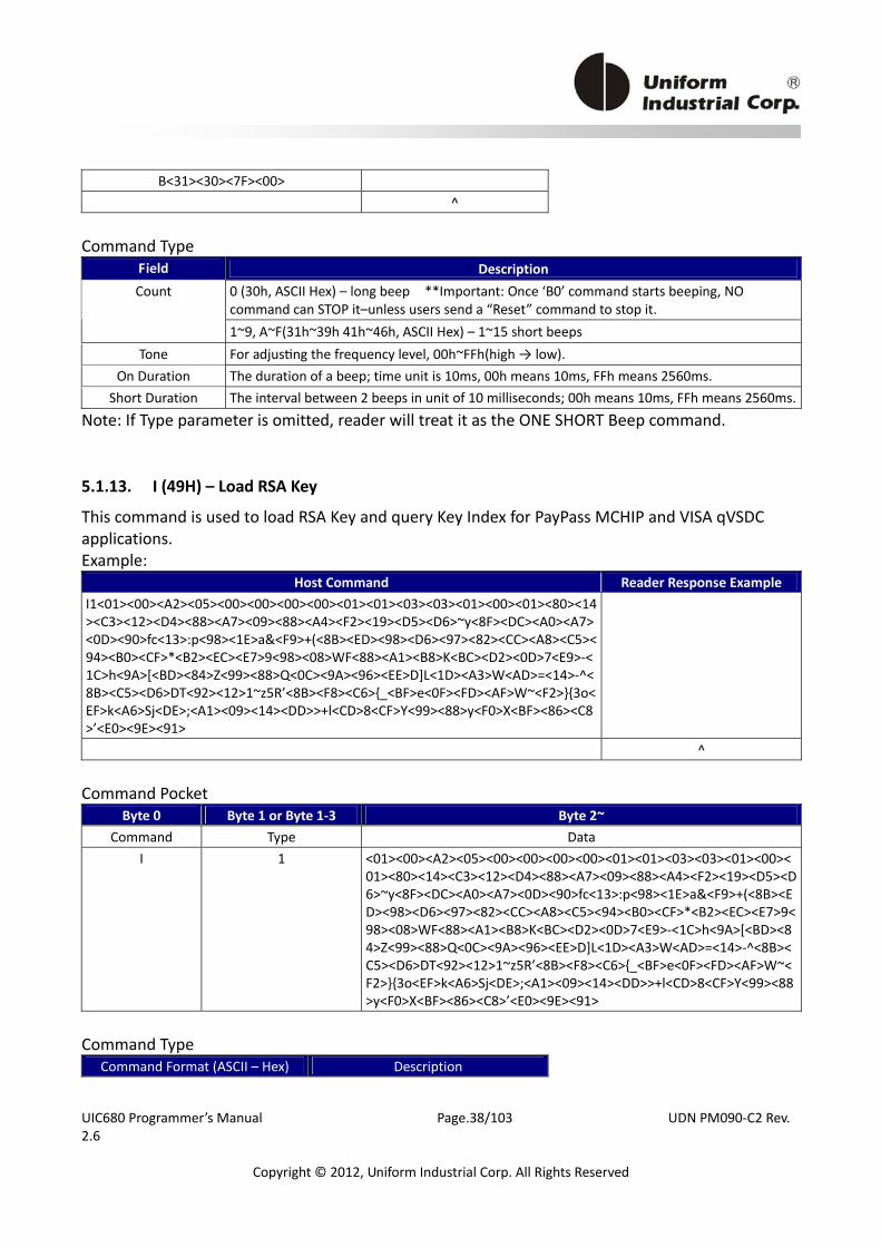
5.1.13. I (49H) – Load RSA Key
This command is used to load RSA Key and query Key Index for PayPass MCHIP and VISA qVSDC applications. Example:
Host Command Reader Response Example I1<01><00><A2><05><00><00><00><00><01><01><03><03><01><00><01><80><14><C3><12><D4><88><A7><09><88><A4><F2><19><D5><D6>~y<8F><DC><A0><A7><0D><90>fc<13>:p<98><1E>a&<F9>+(<8B><ED><98><D6><97><82><CC><A8><C5><94><B0><CF>*<B2><EC><E7>9<98><08>WF<88><A1><B8>K<BC><D2><0D>7<E9>‐<1C>h<9A>[<BD><84>Z<99><88>Q<0C><9A><96><EE>D]L<1D><A3>W<AD>=<14>‐^<8B><C5><D6>DT<92><12>1~z5R’<8B><F8><C6>{_<BF>e<0F><FD><AF>W~<F2>}{3o<EF>k<A6>Sj<DE>;<A1><09><14><DD>>+l<CD>8<CF>Y<99><88>y<F0>X<BF><86><C8>’<E0><9E><91>
^ Command Pocket
Byte 0 Byte 1 or Byte 1‐3 Byte 2~ Command Type Data
I 1 <01><00><A2><05><00><00><00><00><01><01><03><03><01><00><01><80><14><C3><12><D4><88><A7><09><88><A4><F2><19><D5><D6>~y<8F><DC><A0><A7><0D><90>fc<13>:p<98><1E>a&<F9>+(<8B><ED><98><D6><97><82><CC><A8><C5><94><B0><CF>*<B2><EC><E7>9<98><08>WF<88><A1><B8>K<BC><D2><0D>7<E9>‐<1C>h<9A>[<BD><84>Z<99><88>Q<0C><9A><96><EE>D]L<1D><A3>W<AD>=<14>‐^<8B><C5><D6>DT<92><12>1~z5R’<8B><F8><C6>{_<BF>e<0F><FD><AF>W~<F2>}{3o<EF>k<A6>Sj<DE>;<A1><09><14><DD>>+l<CD>8<CF>Y<99><88>y<F0>X<BF><86><C8>’<E0><9E><91>
Command Type
Command Format (ASCII – Hex) Description
UIC680 Programmer’s Manual Page.39/103 UDN PM090‐C2 Rev. 2.6
Copyright © 2012, Uniform Industrial Corp. All Rights Reserved
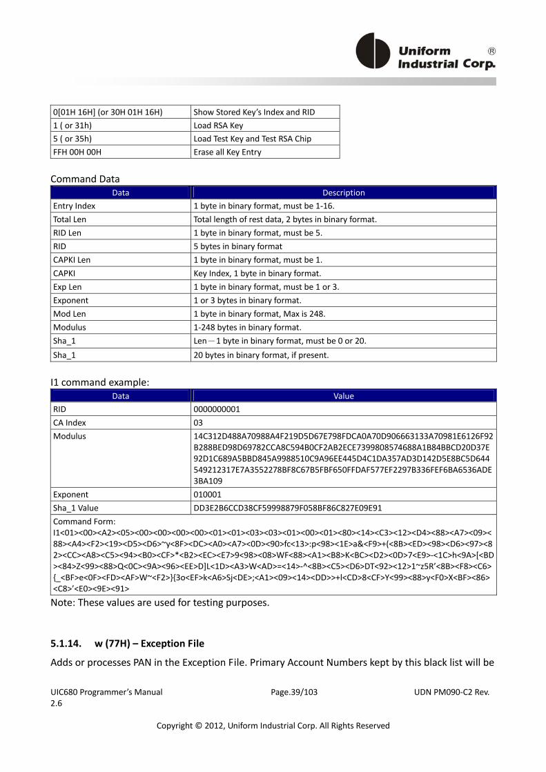
0[01H 16H] (or 30H 01H 16H) Show Stored Key’s Index and RID 1 ( or 31h) Load RSA Key 5 ( or 35h) Load Test Key and Test RSA Chip FFH 00H 00H Erase all Key Entry Command Data
Data Description Entry Index 1 byte in binary format, must be 1‐16. Total Len Total length of rest data, 2 bytes in binary format. RID Len 1 byte in binary format, must be 5. RID 5 bytes in binary format CAPKI Len 1 byte in binary format, must be 1. CAPKI Key Index, 1 byte in binary format. Exp Len 1 byte in binary format, must be 1 or 3. Exponent 1 or 3 bytes in binary format. Mod Len 1 byte in binary format, Max is 248. Modulus 1‐248 bytes in binary format. Sha_1 Len-1 byte in binary format, must be 0 or 20. Sha_1 20 bytes in binary format, if present. I1 command example:
Data Value RID 0000000001 CA Index 03 Modulus 14C312D488A70988A4F219D5D67E798FDCA0A70D906663133A70981E6126F92
B288BED98D69782CCA8C594B0CF2AB2ECE7399808574688A1B84BBCD20D37E92D1C689A5BBD845A9988510C9A96EE445D4C1DA357AD3D142D5E8BC5D644549212317E7A3552278BF8C67B5FBF650FFDAF577EF2297B336FEF6BA6536ADE3BA109
Exponent 010001 Sha_1 Value DD3E2B6CCD38CF59998879F058BF86C827E09E91 Command Form: I1<01><00><A2><05><00><00><00><00><01><01><03><03><01><00><01><80><14><C3><12><D4><88><A7><09><88><A4><F2><19><D5><D6>~y<8F><DC><A0><A7><0D><90>fc<13>:p<98><1E>a&<F9>+(<8B><ED><98><D6><97><82><CC><A8><C5><94><B0><CF>*<B2><EC><E7>9<98><08>WF<88><A1><B8>K<BC><D2><0D>7<E9>‐<1C>h<9A>[<BD><84>Z<99><88>Q<0C><9A><96><EE>D]L<1D><A3>W<AD>=<14>‐^<8B><C5><D6>DT<92><12>1~z5R’<8B><F8><C6>{_<BF>e<0F><FD><AF>W~<F2>}{3o<EF>k<A6>Sj<DE>;<A1><09><14><DD>>+l<CD>8<CF>Y<99><88>y<F0>X<BF><86><C8>’<E0><9E><91>
Note: These values are used for testing purposes.
5.1.14. w (77H) – Exception File
Adds or processes PAN in the Exception File. Primary Account Numbers kept by this black list will be

UIC680 Programmer’s Manual Page.40/103 UDN PM090‐C2 Rev. 2.6
Copyright © 2012, Uniform Industrial Corp. All Rights Reserved
denied for transactions. Command Pocket
Byte 0 Byte 1 Byte 2~ Command Type Data
w 2 <10>6011111111111117 Command Type ASCII – Hex Value Description
0 ( or 30h) Erase Exception File 1 ( or 31h) Report counts of PANs in the Exception File 2 ( or 32h) Add a PAN to the file, 272 entries max. 3 ( or 33h) Query if a PAN exists in the Exception File 4 ( or 34h) Request a certain PAN from the Exception File
Command Data
Type Description 2 ( or 32h) 3 ( or 33h)
data length(1 byte) + PAN(up to 19 bytes ASCII ‘0’~’9’)
4 ( or 34h) 2 bytes long, range from 0000h to 010Fh Response data format
Type Description 1 ( or 31h) Return 2‐byte binary number ‐‐ the total number of PANs in the file. 3 ( or 33h) Return ‘^’ if PAN exists; else, return ‘*’. 4 ( or 34h) Return primary account number; else, return 00h.
w1 Example:
Host Command Reader Response Examplew1 <00><02>
w2<10>6011111111111117 ^
w3<10>6011111111111117 ^
w4<00>02> <10>6011111111111117
UIC680 Programmer’s Manual Page.41/103 UDN PM090‐C2 Rev. 2.6
Copyright © 2012, Uniform Industrial Corp. All Rights Reserved
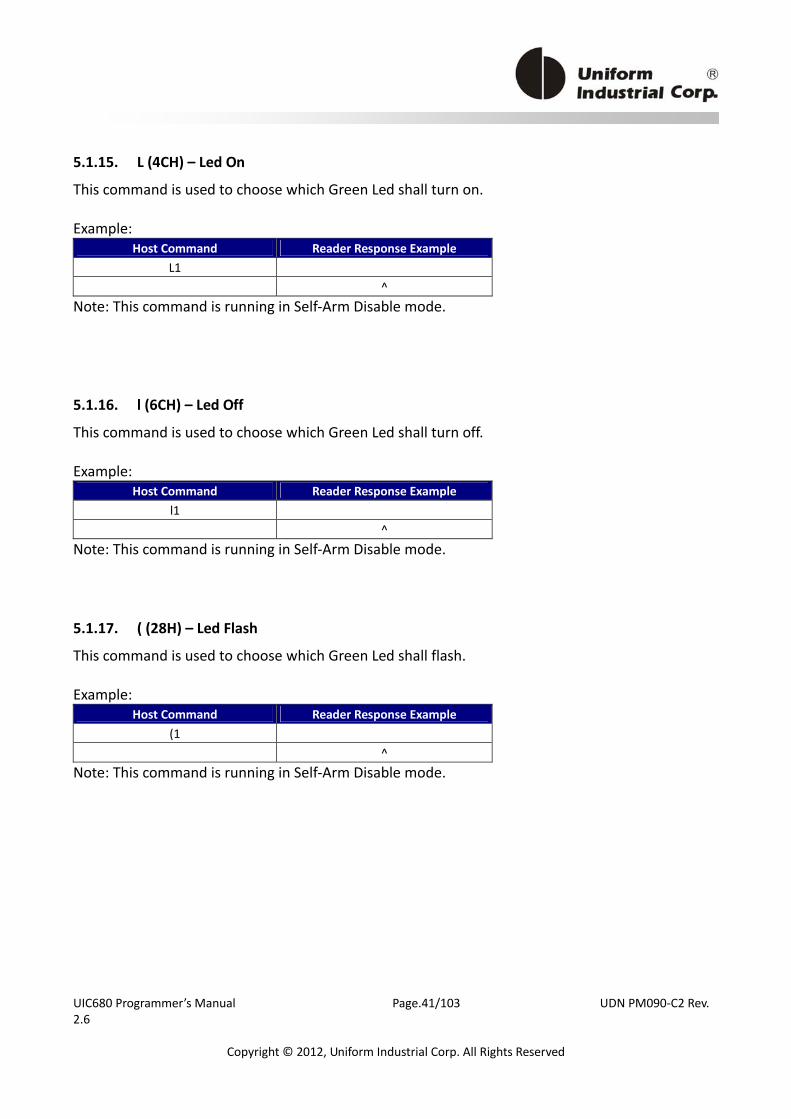
5.1.15. L (4CH) – Led On
This command is used to choose which Green Led shall turn on. Example:
Host Command Reader Response Example L1 ^
Note: This command is running in Self‐Arm Disable mode.
5.1.16. l (6CH) – Led Off
This command is used to choose which Green Led shall turn off. Example:
Host Command Reader Response Example l1 ^
Note: This command is running in Self‐Arm Disable mode.
5.1.17. ( (28H) – Led Flash
This command is used to choose which Green Led shall flash. Example:
Host Command Reader Response Example (1 ^
Note: This command is running in Self‐Arm Disable mode.
UIC680 Programmer’s Manual Page.42/103 UDN PM090‐C2 Rev. 2.6
Copyright © 2012, Uniform Industrial Corp. All Rights Reserved
5.2. General Application
The default setting of the UIC680 reader, Self‐Arm mode, is mainly used to simplify the process so that the host does not need to communicate back and forth with the reader. In this situation, the UIC680 acts like a general magnetic stripe card reader. Whenever it senses the card it will try to decode the card data automatically and send out the decoded data to the host if the process is successful. Otherwise, no information is sent out. If the application would like to take the whole control on the reader, we recommend the user to use the “Host‐Polled” mode instead of the “Self‐Arm” mode. It can be done by either sending “Self‐Arm” disable command or changing default setting in the reader configuration. Once the UIC680 receives the Self‐Arm disable command, ‘H0’ (see the command description section), it will turn off the auto‐read function and then wait for the “Arm‐to‐Read” command, ‘P’ (50h) prepared for the next transaction. Since the Self‐Arm disable command won’t change the EEPROM setting, the UIC680 will turn back to the Self‐Arm mode in the next power cycling. Besides, the Self‐Arm enable command, ‘H1’, can also bring the UIC680 back to the Self‐Arm mode. To disable the Self‐Arm mode permanently, the host needs to set the EEPROM value of the UIC680. The configuration command ‘SA' (see the Configuration Guide) saves the setting into the EEPROM of the UIC680 and keeps the value until the next change. We recommend users to use Protocol 2 (USI2) in their “host‐polled” applications. This protocol contains the header, message counter and block check character. This is better than using Protocol 0(USI0) or Protocol 1(USI1) at it can prevent the data to be misinterpreted but requires more redundant bytes.
UIC680 Programmer’s Manual Page.43/103 UDN PM090‐C2 Rev. 2.6
Copyright © 2012, Uniform Industrial Corp. All Rights Reserved
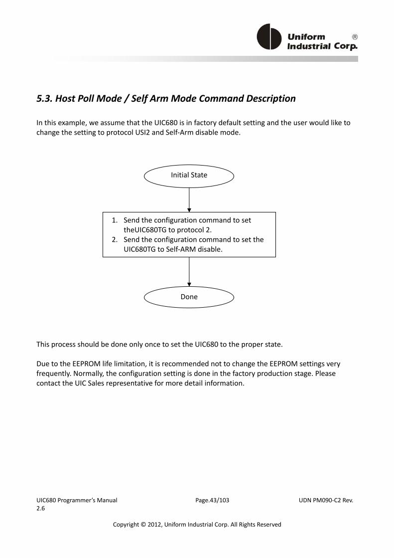
5.3. Host Poll Mode / Self Arm Mode Command Description
In this example, we assume that the UIC680 is in factory default setting and the user would like to change the setting to protocol USI2 and Self‐Arm disable mode.
This process should be done only once to set the UIC680 to the proper state. Due to the EEPROM life limitation, it is recommended not to change the EEPROM settings very frequently. Normally, the configuration setting is done in the factory production stage. Please contact the UIC Sales representative for more detail information.
Initial State
1. Send the configuration command to set theUIC680TG to protocol 2.
2. Send the configuration command to set the UIC680TG to Self‐ARM disable.
Done

UIC680 Programmer’s Manual Page.44/103 UDN PM090‐C2 Rev. 2.6
Copyright © 2012, Uniform Industrial Corp. All Rights Reserved
Self‐Arm Mode transaction process example flow
DefaultSelf‐Arm Mode
Return Error Code? TM<01>Command
Tap Card
54/55 CommandSet Transaction Time
T1 CommandSet Amount
Reader Initial
Start new transaction
No
Error Code Action
Receive error from reader
Terminal/ControllerAction
Start Transaction with amount
Return Error Code Process
Terminal/Controller Action
Reader Setting Command
Reader Transaction Command
Tap Contactless Card
Yes
DWE Command
Wait amount to start transaction?
No
Yes
Figure 5‐1
UIC680 Programmer’s Manual Page.45/103 UDN PM090‐C2 Rev. 2.6
Copyright © 2012, Uniform Industrial Corp. All Rights Reserved
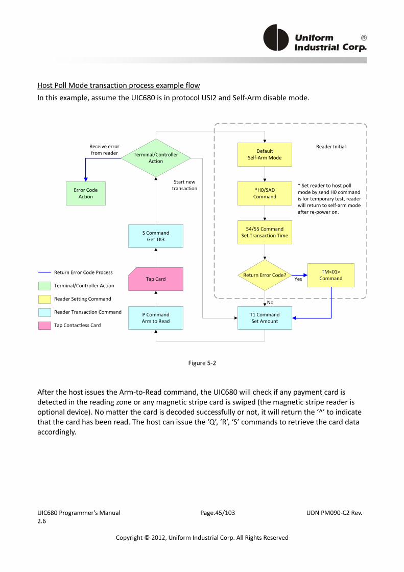
Host Poll Mode transaction process example flow In this example, assume the UIC680 is in protocol USI2 and Self‐Arm disable mode.
DefaultSelf‐Arm Mode
*H0/SAD Command
Return Error Code?
P CommandArm to Read
TM<01>CommandTap Card
54/55 CommandSet Transaction Time
T1 CommandSet Amount
S CommandGet TK3
Reader Initial
Start new transaction
No
Error Code Action
Receive error from reader Terminal/Controller
Action
Return Error Code Process
Terminal/Controller Action
Reader Setting Command
Reader Transaction Command
Tap Contactless Card
Yes
* Set reader to host poll mode by send H0 command is for temporary test, reader will return to self‐arm mode after re‐power on.
Figure 5‐2
After the host issues the Arm‐to‐Read command, the UIC680 will check if any payment card is detected in the reading zone or any magnetic stripe card is swiped (the magnetic stripe reader is optional device). No matter the card is decoded successfully or not, it will return the ‘^’ to indicate that the card has been read. The host can issue the ‘Q’, ‘R’, ‘S’ commands to retrieve the card data accordingly.
UIC680 Programmer’s Manual Page.46/103 UDN PM090‐C2 Rev. 2.6
Copyright © 2012, Uniform Industrial Corp. All Rights Reserved
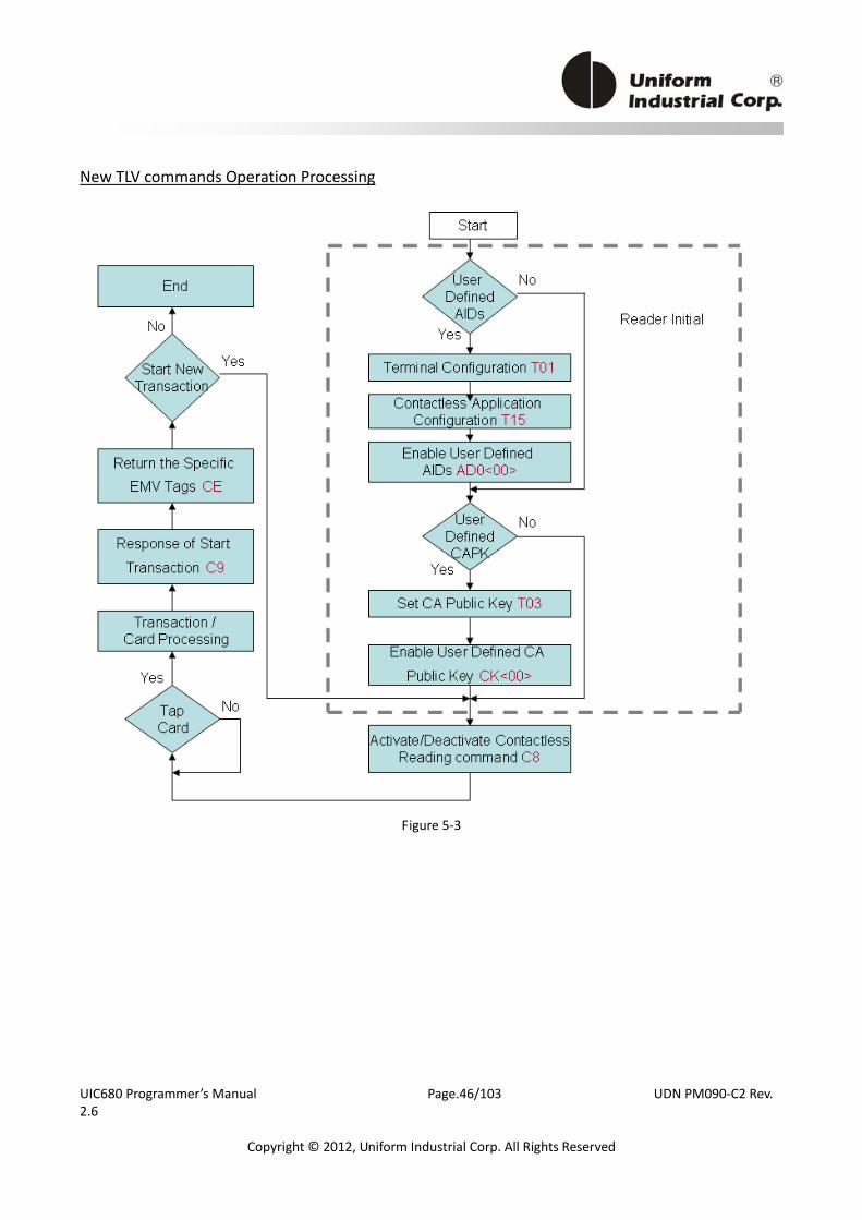
New TLV commands Operation Processing
Figure 5‐3

UIC680 Programmer’s Manual Page.47/103 UDN PM090‐C2 Rev. 2.6
Copyright © 2012, Uniform Industrial Corp. All Rights Reserved
5.3.1. H (48H) – Self‐Arm function disable/enable
Used for controlling Contactless auto read function temporarily. Command Pocket
Byte 0 Byte 1 Command Type
H 0 Command Type
ASCII ‐ Hex 1 Byte Value Description 0 ( or 30h) Self Arm Disable 1 ( or 31h) Self Arm Enable
Example: Host Command Reader Response Example
H0 ^
Note: UIC680 cannot perform the Self‐Arm enable command for the contactless payment card reading under the following conditions: 1. The payment card is decoded successfully and the UIC680 is waiting for the card to be
removed from the reading zone. 2. The payment card is failed to decode and the UIC680 is waiting for the card to be removed
from the reading zone.
5.3.2. SAx(53h 41h x) - Self‐Arm Mode Enable/Disable
Note: the command is only using in BLP protocol Command Pocket
Byte 0‐1 Byte 2 Command Enable/Disable
SA E/D Command Type
Type Description D (44h) Disable E (45h) Enable
Example: Host Command Reader Response Example
SAE ^

UIC680 Programmer’s Manual Page.48/103 UDN PM090‐C2 Rev. 2.6
Copyright © 2012, Uniform Industrial Corp. All Rights Reserved
5.3.3. TMx(54h 4Dh x) - Set Error Code output Enable/ Disable
Note: the command is only using in BLP protocol Command Pocket
Byte 0‐1 Byte 2 Command Enable/Disable
TM <01>/<00> Command Type
Type Description 00 Disable 01 Enable
Example:
Host Command Reader Response Example TM<01>
^
5.3.4. P (50H) – Arm to Read
1. Clears data buffers. 2. Transmits command acknowledgement (‘^’ 5EH) if successful. 3. Waiting for and detect approaching card. 4. The LED1 will light on and then turn off after a successful reading or a MIFARE card being
detected. Example:
Host Command Reader Response Example P ^
Note: 1. After an Arm to Read command is received and acknowledged the only valid commands that
will be accepted for execution are: <ESC> “Abort” and ‘$’ “Status”. 2. Reader will NOT send out track data automatically; the host should issue the ‘Q’, ‘R’, ‘S’, ‘U’
commands to get the corresponding track data. 3. In the Self‐Arm mode, it is not necessary to send this command. If this command is sent, it will
temporarily override the Self‐Arm mode.
5.3.5. p (70H) – Arm to Read (Used for Manufacturing Test Only)
Equivalent to the 'P' command, except the card read acknowledgement which is not the ‘^’ character.
UIC680 Programmer’s Manual Page.49/103 UDN PM090‐C2 Rev. 2.6
Copyright © 2012, Uniform Industrial Corp. All Rights Reserved
Example: Host Command Reader Response Example
p ^
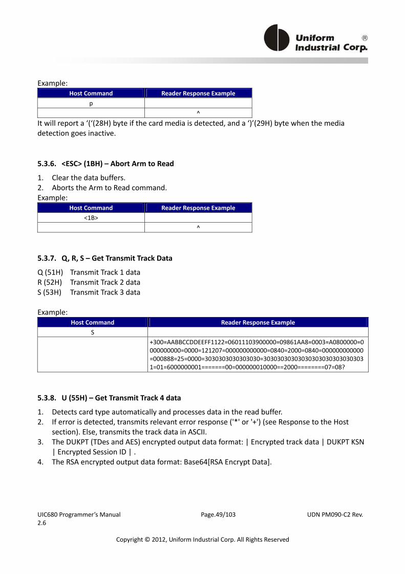
It will report a ‘(‘(28H) byte if the card media is detected, and a ‘)’(29H) byte when the media detection goes inactive.
5.3.6. <ESC> (1BH) – Abort Arm to Read
1. Clear the data buffers. 2. Aborts the Arm to Read command. Example:
Host Command Reader Response Example <1B>
^
5.3.7. Q, R, S – Get Transmit Track Data
Q (51H) Transmit Track 1 data R (52H) Transmit Track 2 data S (53H) Transmit Track 3 data Example:
Host Command Reader Response Example S
+300=AABBCCDDEEFF1122=06011103900000=09861AA8=0003=A0800000=0000000000=0000=121207=000000000000=0840=2000=0840=000000000000=000888=25=0000=3030303030303030=303030303030303030303030303031=01=6000000001=======00=000000010000==2000========07=08?
5.3.8. U (55H) – Get Transmit Track 4 data
1. Detects card type automatically and processes data in the read buffer. 2. If error is detected, transmits relevant error response ('*' or '+') (see Response to the Host
section). Else, transmits the track data in ASCII. 3. The DUKPT (TDes and AES) encrypted output data format: | Encrypted track data | DUKPT KSN
| Encrypted Session ID | . 4. The RSA encrypted output data format: Base64[RSA Encrypt Data].
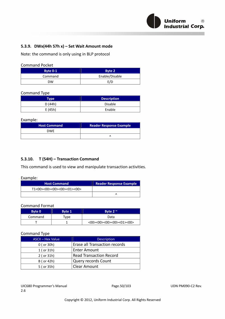
UIC680 Programmer’s Manual Page.50/103 UDN PM090‐C2 Rev. 2.6
Copyright © 2012, Uniform Industrial Corp. All Rights Reserved
5.3.9. DWx(44h 57h x) – Set Wait Amount mode
Note: the command is only using in BLP protocol Command Pocket
Byte 0‐1 Byte 2 Command Enable/Disable
DW E/D Command Type
Type Description D (44h) Disable E (45h) Enable
Example:
Host Command Reader Response Example DWE
^
5.3.10. T (54H) – Transaction Command
This command is used to view and manipulate transaction activities. Example:
Host Command Reader Response ExampleT1<00><00><00><00><01><00>
^ Command Format
Byte 0 Byte 1 Byte 2 ~ Command Type Data
T 1 <00><00><00><00><01><00> Command Type
ASCII – Hex Value Description 0 ( or 30h) Erase all Transaction records 1 ( or 31h) Enter Amount 2 ( or 31h) Read Transaction Record B ( or 42h) Query records Count 5 ( or 35h) Clear Amount
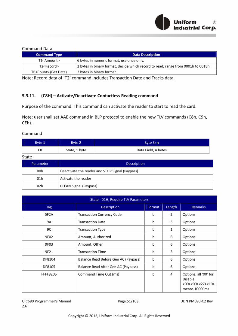
UIC680 Programmer’s Manual Page.51/103 UDN PM090‐C2 Rev. 2.6
Copyright © 2012, Uniform Industrial Corp. All Rights Reserved
Command Data Command Type Data Description T1<Amount> 6 bytes in numeric format, use once only. T2<Record> 2 bytes in binary format, decide which record to read; range from 0001h to 0018h.
TB<Count> (Get Data) 2 bytes in binary format. Note: Record data of ‘T2’ command includes Transaction Date and Tracks data.
5.3.11. (C8H) – Activate/Deactivate Contactless Reading command
Purpose of the command: This command can activate the reader to start to read the card.
Note: user shall set AAE command in BLP protocol to enable the new TLV commands (C8h, C9h, CEh).
Command
Byte 1 Byte 2 Byte 3+n
C8 State, 1 byte Data Field, n bytes
State Parameter Description
00h Deactivate the reader and STOP Signal (Paypass)
01h Activate the reader
02h CLEAN Signal (Paypass)
State ‐ 01H, Require TLV Parameters
Tag Description Format Length Remarks
5F2A Transaction Currency Code b 2 Options
9A Transaction Date b 3 Options
9C Transaction Type b 1 Options
9F02 Amount, Authorized b 6 Options
9F03 Amount, Other b 6 Options
9F21 Transaction Time b 3 Options
DF8104 Balance Read Before Gen AC (Paypass) b 6 Options
DF8105 Balance Read After Gen AC (Paypass) b 6 Options
FFFF8205 Command Time Out (ms) b 4 Options, all ‘00’ for Disable, <00><00><27><10> means 10000ms
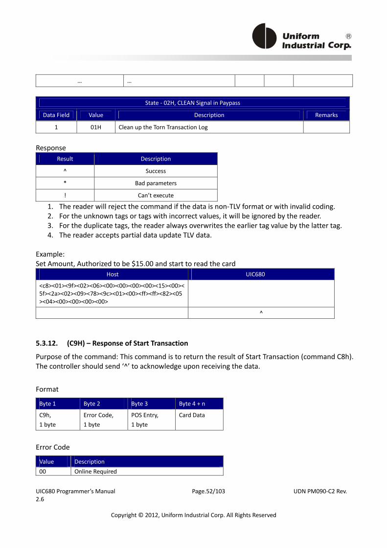
UIC680 Programmer’s Manual Page.52/103 UDN PM090‐C2 Rev. 2.6
Copyright © 2012, Uniform Industrial Corp. All Rights Reserved
… …
State ‐ 02H, CLEAN Signal in Paypass
Data Field Value Description Remarks
1 01H Clean up the Torn Transaction Log
Response
Result Description
^ Success
* Bad parameters
! Can’t execute
1. The reader will reject the command if the data is non‐TLV format or with invalid coding. 2. For the unknown tags or tags with incorrect values, it will be ignored by the reader. 3. For the duplicate tags, the reader always overwrites the earlier tag value by the latter tag. 4. The reader accepts partial data update TLV data.
Example: Set Amount, Authorized to be $15.00 and start to read the card
Host UIC680
<c8><01><9f><02><06><00><00><00><00><15><00><5f><2a><02><09><78><9c><01><00><ff><ff><82><05><04><00><00><00><00>
^
5.3.12. (C9H) – Response of Start Transaction
Purpose of the command: This command is to return the result of Start Transaction (command C8h). The controller should send ‘^’ to acknowledge upon receiving the data.
Format
Byte 1 Byte 2 Byte 3 Byte 4 + n
C9h, 1 byte
Error Code, 1 byte
POS Entry, 1 byte
Card Data
Error Code
Value Description 00 Online Required

UIC680 Programmer’s Manual Page.53/103 UDN PM090‐C2 Rev. 2.6
Copyright © 2012, Uniform Industrial Corp. All Rights Reserved
01 Offline Approved 02 Offline Declined 03 Card not support 04 Initiation error 06 Empty candidate list 07 C8 Command Time out 08 Card block 0B Transaction error 0C Authentication error 0D More card 0F Time out of Online Required ( DPAS) 12 Try Again *1 20 See Phone *1 39 Transaction Terminate 60 Online Approved 61 Online Declined 62 Online Approved of Issuer Script 63 Online Decline of Issuer Script 64 Unable Go Online Offline Approved 65 Unable Go Online Offline Declined 86 Empty candidate list, try other interface 8C Authentication error, try other interface Note *1: In order to meet the requirement of Kernel, the Host shall resend C8 command with all same parameters in 1st transaction. POS Entry Bit 7 Bit 6 Bit 5 – 0 Description 0 0 000001 Contactless – Visa qVSDC Card 0 0 000010 Contactless – Visa MSD Card 0 0 000011 Contactless – PayPass Mchip Card 0 0 000100 Contactless – PayPass Magstripe Card 0 0 000101 Contactless – AMEX EMV Card 0 0 000110 Contactless – AMEX MSD Card 0 0 000111 Contactless – Discover DPAS Card 0 0 001000 Contactless – Discover Zip Card 0 0 001001 Contactless – Google Wallet 0 0 001010 Contactless – ISIS 0 0 010000 Contactless – Mifare 0 1 000001 Mag stripe card 1 0 000000 No payment card, no additional data available. Bit 7 = 0, the additional data is available. Bit 7 = 1, no additional data.
Card Data
The number of the track in the card data is set by CKx. By default, all 3 tracks are output. It
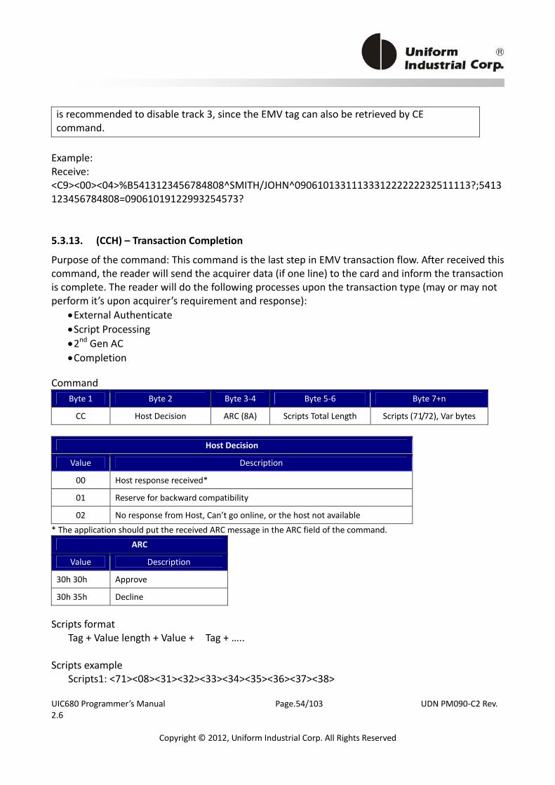
UIC680 Programmer’s Manual Page.54/103 UDN PM090‐C2 Rev. 2.6
Copyright © 2012, Uniform Industrial Corp. All Rights Reserved
is recommended to disable track 3, since the EMV tag can also be retrieved by CE command. Example: Receive: <C9><00><04>%B5413123456784808^SMITH/JOHN^0906101331113331222222232511113?;5413123456784808=09061019122993254573?
5.3.13. (CCH) – Transaction Completion
Purpose of the command: This command is the last step in EMV transaction flow. After received this command, the reader will send the acquirer data (if one line) to the card and inform the transaction is complete. The reader will do the following processes upon the transaction type (may or may not perform it’s upon acquirer’s requirement and response):
• External Authenticate • Script Processing • 2nd Gen AC • Completion
Command
Byte 1 Byte 2 Byte 3‐4 Byte 5‐6 Byte 7+n
CC Host Decision ARC (8A) Scripts Total Length Scripts (71/72), Var bytes
Host Decision
Value Description
00 Host response received*
01 Reserve for backward compatibility
02 No response from Host, Can’t go online, or the host not available
* The application should put the received ARC message in the ARC field of the command.
ARC
Value Description
30h 30h Approve
30h 35h Decline
Scripts format
Tag + Value length + Value + Tag + ….. Scripts example
Scripts1: <71><08><31><32><33><34><35><36><37><38>
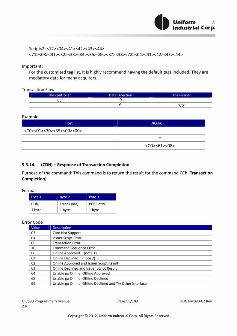
UIC680 Programmer’s Manual Page.55/103 UDN PM090‐C2 Rev. 2.6
Copyright © 2012, Uniform Industrial Corp. All Rights Reserved
Scripts2: <72><04><41><42><43><44> <71><08><31><32><33><34><35><36><37><38><72><04><41><42><43><44>
Important:
For the customized tag list, it is highly recommend having the default tags included. They are mediatory data for many acquirers.
Transaction Flow
The controller Data Direction The Reader ‘CC’ ‘CD’
Example:
Host UIC680
<CC><01><30><35><00><00>
^
<CD><61><08>
5.3.14. (CDH) – Response of Transaction Completion
Purpose of the command: This command is to return the result for the command CCh (Transaction Completion). Format
Byte 1 Byte 2 Byte 3
CDh, 1 byte
Error Code, 1 byte
POS Entry, 1 byte
Error Code
Value Description 03 Card Not Support 04 Issuer Script Error 0B Transaction Error 10 Command Sequence Error 60 Online Approved (note 1) 61 Online Declined (note 2) 62 Online Approved and Issuer Script Result 63 Online Declined and Issuer Script Result 64 Unable go Online, Offline Approved 65 Unable go Online, Offline Declined 66 Unable go Online, Offline Declined and Try Other Interface
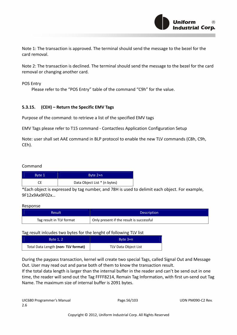
UIC680 Programmer’s Manual Page.56/103 UDN PM090‐C2 Rev. 2.6
Copyright © 2012, Uniform Industrial Corp. All Rights Reserved
Note 1: The transaction is approved. The terminal should send the message to the bezel for the card removal. Note 2: The transaction is declined. The terminal should send the message to the bezel for the card removal or changing another card. POS Entry
Please refer to the “POS Entry” table of the command “C9h” for the value.
5.3.15. (CEH) – Return the Specific EMV Tags
Purpose of the command: to retrieve a list of the specified EMV tags
EMV Tags please refer to T15 command ‐ Contactless Application Configuration Setup
Note: user shall set AAE command in BLP protocol to enable the new TLV commands (C8h, C9h, CEh).
Command
Byte 1 Byte 2+n
CE Data Object List * (n bytes)
*Each object is expressed by tag number, and 78H is used to delimit each object. For example, 9F12x9Ax9F02x… Response
Result Description
Tag result in TLV format Only present if the result is successful
Tag result inlcudes two bytes for the lenght of following TLV list
Byte 1, 2 Byte 3+n
Total Data Length (non‐ TLV format) TLV Data Object List
During the paypass transaction, kernel will create two special Tags, called Signal Out and Message Out. User may read out and parse both of them to know the transaction result. If the total data length is larger than the internal buffer in the reader and can’t be send out in one time, the reader will send out the Tag FFFF8214, Remain Tag Information, with first un‐send out Tag Name. The maximum size of internal buffer is 2091 bytes.
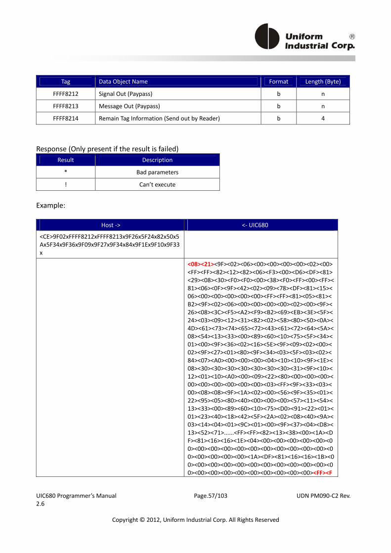
UIC680 Programmer’s Manual Page.57/103 UDN PM090‐C2 Rev. 2.6
Copyright © 2012, Uniform Industrial Corp. All Rights Reserved
Tag Data Object Name Format Length (Byte)
FFFF8212 Signal Out (Paypass) b n
FFFF8213 Message Out (Paypass) b n
FFFF8214 Remain Tag Information (Send out by Reader) b 4
Response (Only present if the result is failed)
Result Description
* Bad parameters
! Can’t execute
Example:
Host ‐> <‐ UIC680
<CE>9F02xFFFF8212xFFFF8213x9F26x5F24x82x50x5Ax5F34x9F36x9F09x9F27x9F34x84x9F1Ex9F10x9F33x
<08><21><9F><02><06><00><00><00><00><02><00><FF><FF><82><12><82><06><F3><00><D6><DF><81><29><08><30><F0><F0><00><38><F0><FF><00><FF><81><06><0F><9F><42><02><09><78><DF><81><15><06><00><00><00><00><00><FF><FF><81><05><81><B2><9F><02><06><00><00><00><00><02><00><9F><26><08><3C><F5><A2><F9><B2><69><EB><3E><5F><24><03><09><12><31><82><02><58><80><50><0A><4D><61><73><74><65><72><43><61><72><64><5A><08><54><13><33><00><89><60><10><75><5F><34><01><00><9F><36><02><16><5E><9F><09><02><00><02><9F><27><01><80><9F><34><03><5F><03><02><84><07><A0><00><00><00><04><10><10><9F><1E><08><30><30><30><30><30><30><30><31><9F><10><12><01><10><A0><00><09><22><80><00><00><00><00><00><00><00><00><00><03><FF><9F><33><03><00><08><08><9F><1A><02><00><56><9F><35><01><22><95><05><80><40><00><00><00><57><11><54><13><33><00><89><60><10><75><D0><91><22><01><01><23><40><18><42><5F><2A><02><08><40><9A><03><14><04><01><9C><01><00><9F><37><04><D8><13><52><71>......<FF><FF><82><13><38><00><1A><DF><81><16><16><1E><04><00><00><00><00><00><00><00><00><00><00><00><00><00><00><00><00><00><00><00><00><00><1A><DF><81><16><16><1B><00><00><00><00><00><00><00><00><00><00><00><00><00><00><00><00><00><00><00><00><00><FF><F
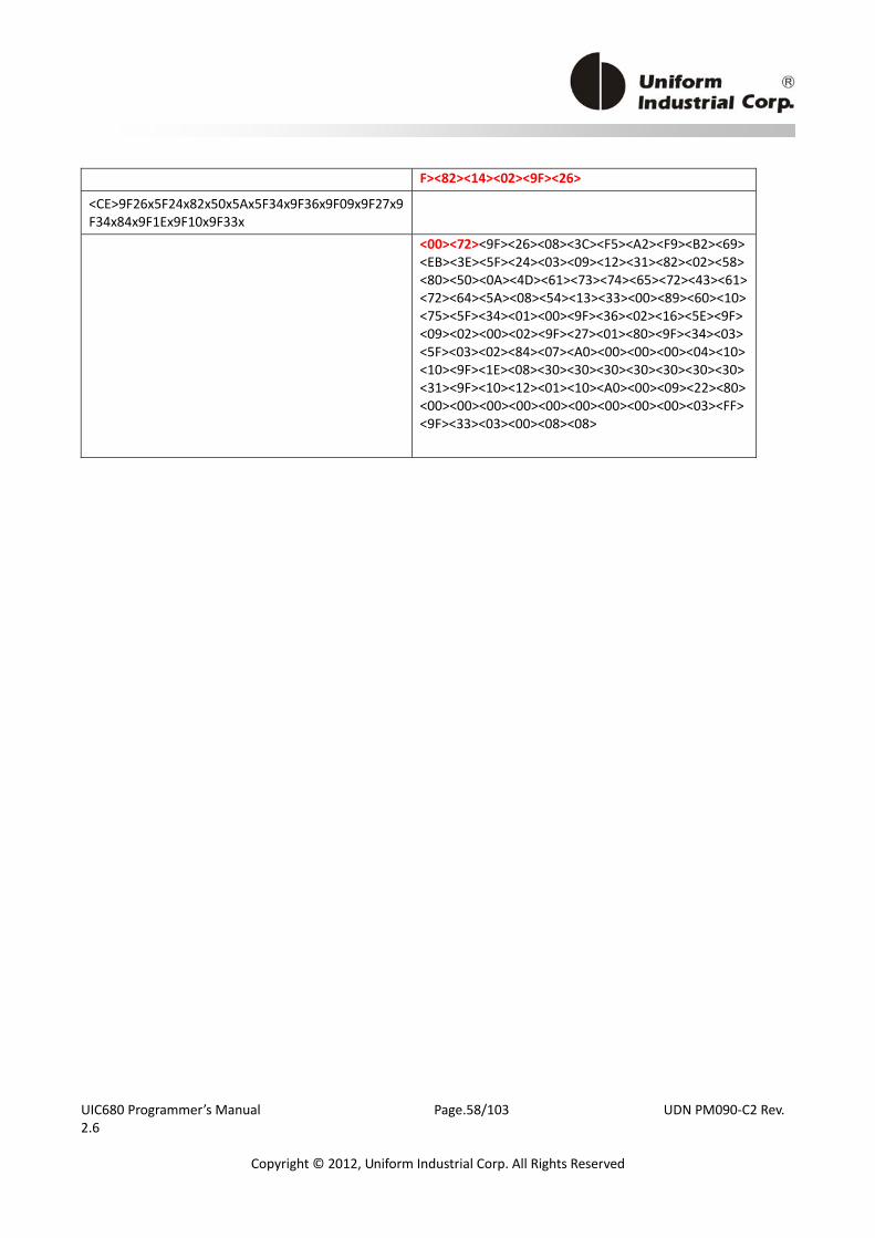
UIC680 Programmer’s Manual Page.58/103 UDN PM090‐C2 Rev. 2.6
Copyright © 2012, Uniform Industrial Corp. All Rights Reserved
F><82><14><02><9F><26>
<CE>9F26x5F24x82x50x5Ax5F34x9F36x9F09x9F27x9F34x84x9F1Ex9F10x9F33x
<00><72><9F><26><08><3C><F5><A2><F9><B2><69><EB><3E><5F><24><03><09><12><31><82><02><58><80><50><0A><4D><61><73><74><65><72><43><61><72><64><5A><08><54><13><33><00><89><60><10><75><5F><34><01><00><9F><36><02><16><5E><9F><09><02><00><02><9F><27><01><80><9F><34><03><5F><03><02><84><07><A0><00><00><00><04><10><10><9F><1E><08><30><30><30><30><30><30><30><31><9F><10><12><01><10><A0><00><09><22><80><00><00><00><00><00><00><00><00><00><03><FF><9F><33><03><00><08><08>
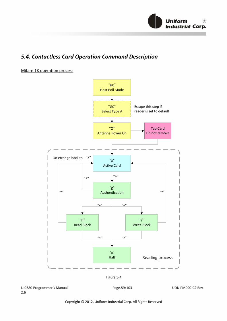
UIC680 Programmer’s Manual Page.59/103 UDN PM090‐C2 Rev. 2.6
Copyright © 2012, Uniform Industrial Corp. All Rights Reserved
5.4. Contactless Card Operation Command Description
Mifare 1K operation process
“H0”Host Poll Mode
“G0”Select Type A
“O”Antenna Power On
“X”Active Card
“h”Read Block
“i”Write Block
“x”Halt
“g”Authentication
Tap CardDo not remove
“^”
“^”“^”
“*”
“*”
“*”
“^”“^”
Escape this step if reader is set to default
On error go back to “X”
Reading process
Figure 5‐4
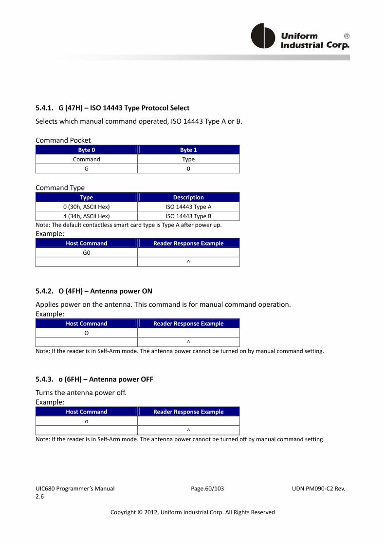
UIC680 Programmer’s Manual Page.60/103 UDN PM090‐C2 Rev. 2.6
Copyright © 2012, Uniform Industrial Corp. All Rights Reserved
5.4.1. G (47H) – ISO 14443 Type Protocol Select Selects which manual command operated, ISO 14443 Type A or B. Command Pocket
Byte 0 Byte 1 Command Type
G 0 Command Type
Type Description 0 (30h, ASCII Hex) ISO 14443 Type A 4 (34h, ASCII Hex) ISO 14443 Type B
Note: The default contactless smart card type is Type A after power up. Example:
Host Command Reader Response Example G0 ^
5.4.2. O (4FH) – Antenna power ON Applies power on the antenna. This command is for manual command operation. Example:
Host Command Reader Response Example O ^
Note: If the reader is in Self‐Arm mode. The antenna power cannot be turned on by manual command setting.
5.4.3. o (6FH) – Antenna power OFF Turns the antenna power off. Example:
Host Command Reader Response Example o ^
Note: If the reader is in Self‐Arm mode. The antenna power cannot be turned off by manual command setting.

UIC680 Programmer’s Manual Page.61/103 UDN PM090‐C2 Rev. 2.6
Copyright © 2012, Uniform Industrial Corp. All Rights Reserved
5.4.4. b (62H) – Request Request command. Command Pocket ‐ ISO 14443 type A
Byte 0 Byte 1 Command Req command
b 52 The request command code is ISO 14443 type A. It can be either 26(REQA) or 52(WUPA). Note: If the [Req command] field does not appear in the request command, reader will set the request mode to WUPA automatically. Command Pocket ‐ ISO 14443 type B
Byte 0 Byte 1 Byte 2 Command AFI PARAM
b 00 00 Note: user shall set G4 to select ISO 14443 Type B while using b<00><00>. Command Description
Byte Description AFI(optional) Binary Hex(00h to FFh), please refer to ISO 14443‐3 for detailed information.
PARAM(optional) Binary Hex(00h to FFh), please refer to ISO 14443‐3 for detailed information. If the [AFI] and [PARAM] fields do not appear in the request command, reader will set the request mode to WUPB automatically. Success Response Data Format
Message Type Description ATQA 2 bytes, type A, Binary Hex ATQB 12 bytes, type B, Binary Hex
Note: If reader response ‘*’ = No card response or No power on the antenna
5.4.5. c (63H) – Anticollision(type A)/Slot‐MARKER(type B)
In type A mode, reader sends the ANTICOLLISION command to the card. In type B mode, reader sends the Slot‐MARKER command to the card. Command Pocket ‐
Card Type Byte 0 Byte 1 ISO 14443 type A c ISO 14443 type B c APn
Command Description
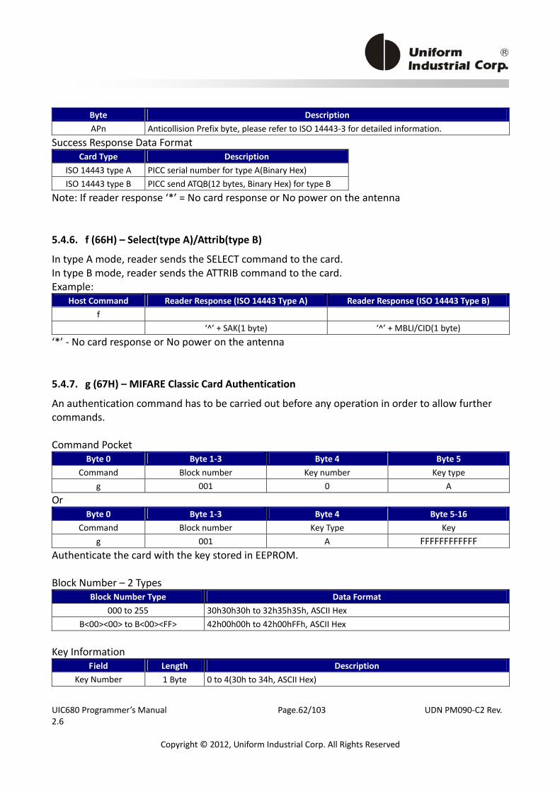
UIC680 Programmer’s Manual Page.62/103 UDN PM090‐C2 Rev. 2.6
Copyright © 2012, Uniform Industrial Corp. All Rights Reserved
Byte Description APn Anticollision Prefix byte, please refer to ISO 14443‐3 for detailed information.
Success Response Data Format Card Type Description
ISO 14443 type A PICC serial number for type A(Binary Hex) ISO 14443 type B PICC send ATQB(12 bytes, Binary Hex) for type B
Note: If reader response ‘*’ = No card response or No power on the antenna
5.4.6. f (66H) – Select(type A)/Attrib(type B) In type A mode, reader sends the SELECT command to the card. In type B mode, reader sends the ATTRIB command to the card. Example:
Host Command Reader Response (ISO 14443 Type A) Reader Response (ISO 14443 Type B) f ‘^’ + SAK(1 byte) ‘^’ + MBLI/CID(1 byte)
‘*’ ‐ No card response or No power on the antenna
5.4.7. g (67H) – MIFARE Classic Card Authentication
An authentication command has to be carried out before any operation in order to allow further commands. Command Pocket
Byte 0 Byte 1‐3 Byte 4 Byte 5 Command Block number Key number Key type
g 001 0 A Or
Byte 0 Byte 1‐3 Byte 4 Byte 5‐16 Command Block number Key Type Key
g 001 A FFFFFFFFFFFF Authenticate the card with the key stored in EEPROM. Block Number – 2 Types
Block Number Type Data Format 000 to 255 30h30h30h to 32h35h35h, ASCII Hex
B<00><00> to B<00><FF> 42h00h00h to 42h00hFFh, ASCII Hex Key Information
Field Length Description Key Number 1 Byte 0 to 4(30h to 34h, ASCII Hex)
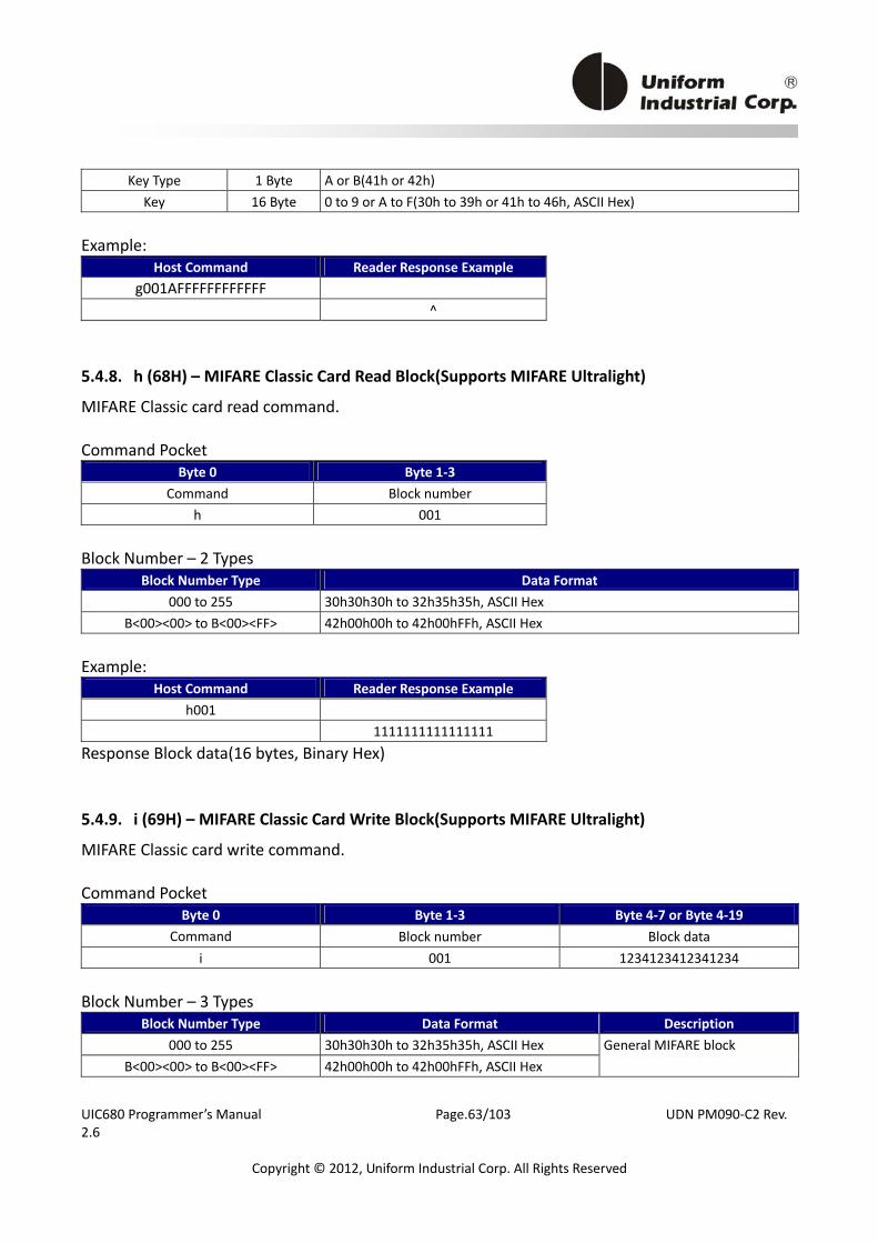
UIC680 Programmer’s Manual Page.63/103 UDN PM090‐C2 Rev. 2.6
Copyright © 2012, Uniform Industrial Corp. All Rights Reserved
Key Type 1 Byte A or B(41h or 42h) Key 16 Byte 0 to 9 or A to F(30h to 39h or 41h to 46h, ASCII Hex)
Example:
Host Command Reader Response Example g001AFFFFFFFFFFFF
^
5.4.8. h (68H) – MIFARE Classic Card Read Block(Supports MIFARE Ultralight)
MIFARE Classic card read command. Command Pocket
Byte 0 Byte 1‐3 Command Block number
h 001 Block Number – 2 Types
Block Number Type Data Format 000 to 255 30h30h30h to 32h35h35h, ASCII Hex
B<00><00> to B<00><FF> 42h00h00h to 42h00hFFh, ASCII Hex Example:
Host Command Reader Response Example h001
1111111111111111 Response Block data(16 bytes, Binary Hex)
5.4.9. i (69H) – MIFARE Classic Card Write Block(Supports MIFARE Ultralight)
MIFARE Classic card write command. Command Pocket
Byte 0 Byte 1‐3 Byte 4‐7 or Byte 4‐19 Command Block number Block data
i 001 1234123412341234 Block Number – 3 Types
Block Number Type Data Format Description 000 to 255 30h30h30h to 32h35h35h, ASCII Hex
B<00><00> to B<00><FF> 42h00h00h to 42h00hFFh, ASCII Hex General MIFARE block
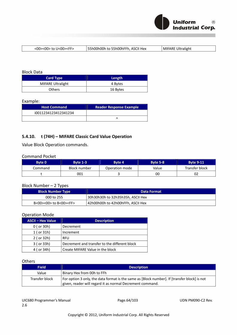
UIC680 Programmer’s Manual Page.64/103 UDN PM090‐C2 Rev. 2.6
Copyright © 2012, Uniform Industrial Corp. All Rights Reserved
<00><00> to U<00><FF> 55h00h00h to 55h00hFFh, ASCII Hex MIFARE Ultralight Block Data
Card Type Length MIFARE Ultralight 4 Bytes
Others 16 Bytes Example:
Host Command Reader Response Example i0011234123412341234
^
5.4.10. t (74H) – MIFARE Classic Card Value Operation
Value Block Operation commands. Command Pocket
Byte 0 Byte 1‐3 Byte 4 Byte 5‐8 Byte 9‐11 Command Block number Operation mode Value Transfer block
t 001 3 00 02 Block Number – 2 Types
Block Number Type Data Format 000 to 255 30h30h30h to 32h35h35h, ASCII Hex
B<00><00> to B<00><FF> 42h00h00h to 42h00hFFh, ASCII Hex Operation Mode
ASCII – Hex Value Description 0 ( or 30h) Decrement 1 ( or 31h) Increment 2 ( or 32h) RFU 3 ( or 33h) Decrement and transfer to the different block 4 ( or 34h) Create MIFARE Value in the block
Others
Field Description Value Binary Hex from 00h to FFh
Transfer block For option 3 only, the data format is the same as [Block number]. If [transfer block] is not given, reader will regard it as normal Decrement command.
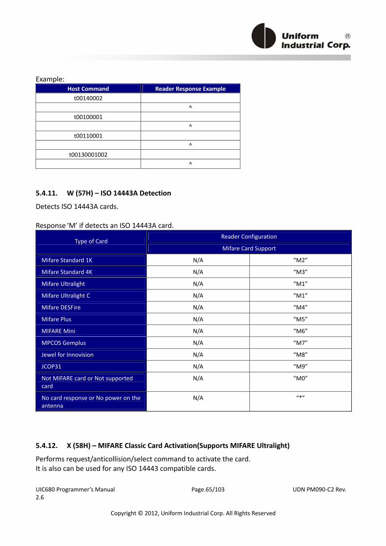
UIC680 Programmer’s Manual Page.65/103 UDN PM090‐C2 Rev. 2.6
Copyright © 2012, Uniform Industrial Corp. All Rights Reserved
Example: Host Command Reader Response Example t00140002
^ t00100001
^ t00110001
^ t00130001002
^
5.4.11. W (57H) – ISO 14443A Detection
Detects ISO 14443A cards. Response ‘M’ if detects an ISO 14443A card.
Reader Configuration Type of Card
Mifare Card Support
Mifare Standard 1K N/A “M2”
Mifare Standard 4K N/A “M3”
Mifare Ultralight N/A “M1”
Mifare Ultralight C N/A “M1”
Mifare DESFire N/A “M4”
Mifare Plus N/A “M5”
MIFARE Mini N/A “M6”
MPCOS Gemplus N/A “M7”
Jewel for Innovision N/A “M8”
JCOP31 N/A “M9”
Not MIFARE card or Not supported card
N/A “M0”
No card response or No power on the antenna
N/A “*”
5.4.12. X (58H) – MIFARE Classic Card Activation(Supports MIFARE Ultralight)
Performs request/anticollision/select command to activate the card. It is also can be used for any ISO 14443 compatible cards.

UIC680 Programmer’s Manual Page.66/103 UDN PM090‐C2 Rev. 2.6
Copyright © 2012, Uniform Industrial Corp. All Rights Reserved
Card Type Description Type A ATQA/SAK/serial number if command executed successfully Type B ATQB(12 bytes) if command executed successfully
Example:
Host Command Reader Response Example X <04><00><08>d<AC>Eq
5.4.13. u (75H) – MIFARE Classic Card Read Sector
MIFARE Classic card read sector command. Command Pocket
Byte 0 Byte 1‐3 Command Block number
u 001 Block Number – 2 Types
Block Number Type Data Format 000 to 255 30h30h30h to 32h35h35h, ASCII Hex
B<00><00> to B<00><FF> 42h00h00h to 42h00hFFh, ASCII Hex Note: For MIFARE Classic 4K, sectors 0~31 contains 4 blocks each and sectors 32~39 contains 16 blocks each. Response Sector data (64/256 bytes, depending on the card) if command executed successfully
5.4.14. v (76H) – MIFARE Classic Card Write Sector
MIFARE Classic card write sector command. Command Pocket
Byte 0 Byte 1‐3 Byte 4~ Command Sector number Sector Data
Sector Number – 2 Types
Block Number Type Data Format 000 to 255 30h30h30h to 32h35h35h, ASCII Hex
B<00><00> to B<00><FF> 42h00h00h to 42h00hFFh, ASCII Hex Sector Data
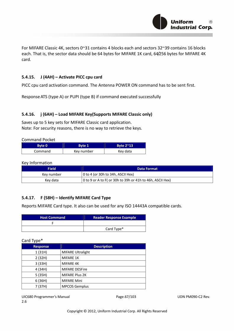
UIC680 Programmer’s Manual Page.67/103 UDN PM090‐C2 Rev. 2.6
Copyright © 2012, Uniform Industrial Corp. All Rights Reserved
For MIFARE Classic 4K, sectors 0~31 contains 4 blocks each and sectors 32~39 contains 16 blocks each. That is, the sector data should be 64 bytes for MIFARE 1K card, 64/256 bytes for MIFARE 4K card.
5.4.15. J (4AH) – Activate PICC cpu card
PICC cpu card activation command. The Antenna POWER ON command has to be sent first. Response ATS (type A) or PUPI (type B) if command executed successfully
5.4.16. j (6AH) – Load MIFARE Key(Supports MIFARE Classic only)
Saves up to 5 key sets for MIFARE Classic card application. Note: For security reasons, there is no way to retrieve the keys. Command Pocket
Byte 0 Byte 1 Byte 2~13 Command Key number Key data
Key Information
Field Data Format Key number 0 to 4 (or 30h to 34h, ASCII Hex) Key data 0 to 9 or A to F( or 30h to 39h or 41h to 46h, ASCII Hex)
5.4.17. F (58H) – Identify MIFARE Card Type
Reports MIFARE Card type. It also can be used for any ISO 14443A compatible cards.
Host Command Reader Response Example F Card Type*
Card Type*
Response Description 1 (31H) MIFARE Ultralight 2 (32H) MIFARE 1K 3 (33H) MIFARE 4K 4 (34H) MIFARE DESFire 5 (35H) MIFARE Plus 2K 6 (36H) MIFARE Mini 7 (37H) MPCOS Gemplus
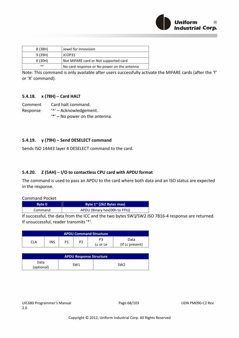
UIC680 Programmer’s Manual Page.68/103 UDN PM090‐C2 Rev. 2.6
Copyright © 2012, Uniform Industrial Corp. All Rights Reserved
8 (38H) Jewel for Innovision 9 (39H) JCOP31 0 (30H) Not MIFARE card or Not supported card ’*’ No card response or No power on the antenna
Note: This command is only available after users successfully activate the MIFARE cards (after the ‘f’ or ‘X’ command).
5.4.18. x (78H) – Card HALT
Comment Card halt command. Response ‘^’ – Acknowledgement. ‘*’ – No power on the antenna.
5.4.19. y (79H) – Send DESELECT command
Sends ISO 14443 layer 4 DESELECT command to the card.
5.4.20. Z (5AH) – I/O to contactless CPU card with APDU format
The command is used to pass an APDU to the card where both data and an ISO status are expected in the response. Command Pocket
Byte 0 Byte 1~ (262 Bytes max) Command APDU (Binary hex(00h to FFh))
If successful, the data from the ICC and the two bytes SW1/SW2 ISO 7816‐4 response are returned. If unsuccessful, reader transmits '*'.
APDU Command Structure
CLA INS P1 P2 P3 Lc or Le
Data (If Lc present)
APDU Response Structure
Data (optional) SW1 SW2
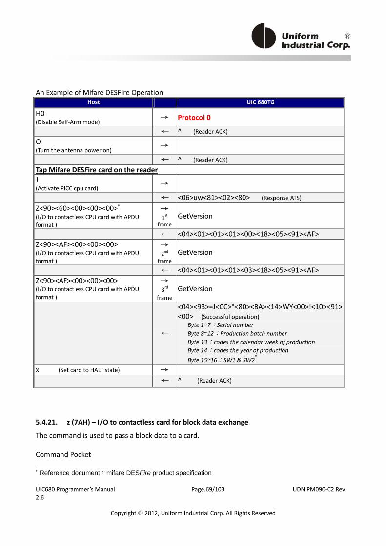
UIC680 Programmer’s Manual Page.69/103 UDN PM090‐C2 Rev. 2.6
Copyright © 2012, Uniform Industrial Corp. All Rights Reserved
An Example of Mifare DESFire Operation Host UIC 680TG
H0 (Disable Self‐Arm mode)
→ Protocol 0
← ^ (Reader ACK) O (Turn the antenna power on) →
← ^ (Reader ACK) Tap Mifare DESFire card on the reader J (Activate PICC cpu card) →
← <06>uw<81><02><80> (Response ATS) Z<90><60><00><00><00>∗ (I/O to contactless CPU card with APDU format )
→ 1st
frameGetVersion
← <04><01><01><01><00><18><05><91><AF> Z<90><AF><00><00><00> (I/O to contactless CPU card with APDU format )
→ 2nd
frameGetVersion
← <04><01><01><01><03><18><05><91><AF>
Z<90><AF><00><00><00> (I/O to contactless CPU card with APDU format )
→ 3rd
frameGetVersion
←
<04><93>=J<CC>"<80><BA><14>WY<00>!<10><91><00> (Successful operation)
Byte 1~7:Serial number Byte 8~12:Production batch number Byte 13:codes the calendar week of production Byte 14:codes the year of production Byte 15~16:SW1 & SW2*
x (Set card to HALT state) → ← ^ (Reader ACK)
5.4.21. z (7AH) – I/O to contactless card for block data exchange
The command is used to pass a block data to a card. Command Pocket ∗ Reference document:mifare DESFire product specification
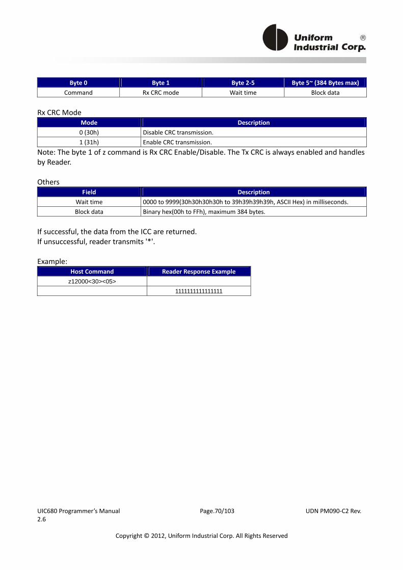
UIC680 Programmer’s Manual Page.70/103 UDN PM090‐C2 Rev. 2.6
Copyright © 2012, Uniform Industrial Corp. All Rights Reserved
Byte 0 Byte 1 Byte 2‐5 Byte 5~ (384 Bytes max) Command Rx CRC mode Wait time Block data
Rx CRC Mode
Mode Description 0 (30h) Disable CRC transmission. 1 (31h) Enable CRC transmission.
Note: The byte 1 of z command is Rx CRC Enable/Disable. The Tx CRC is always enabled and handles by Reader. Others
Field Description Wait time 0000 to 9999(30h30h30h30h to 39h39h39h39h, ASCII Hex) in milliseconds. Block data Binary hex(00h to FFh), maximum 384 bytes.
If successful, the data from the ICC are returned. If unsuccessful, reader transmits '*'. Example:
Host Command Reader Response Example z12000<30><05>
1111111111111111
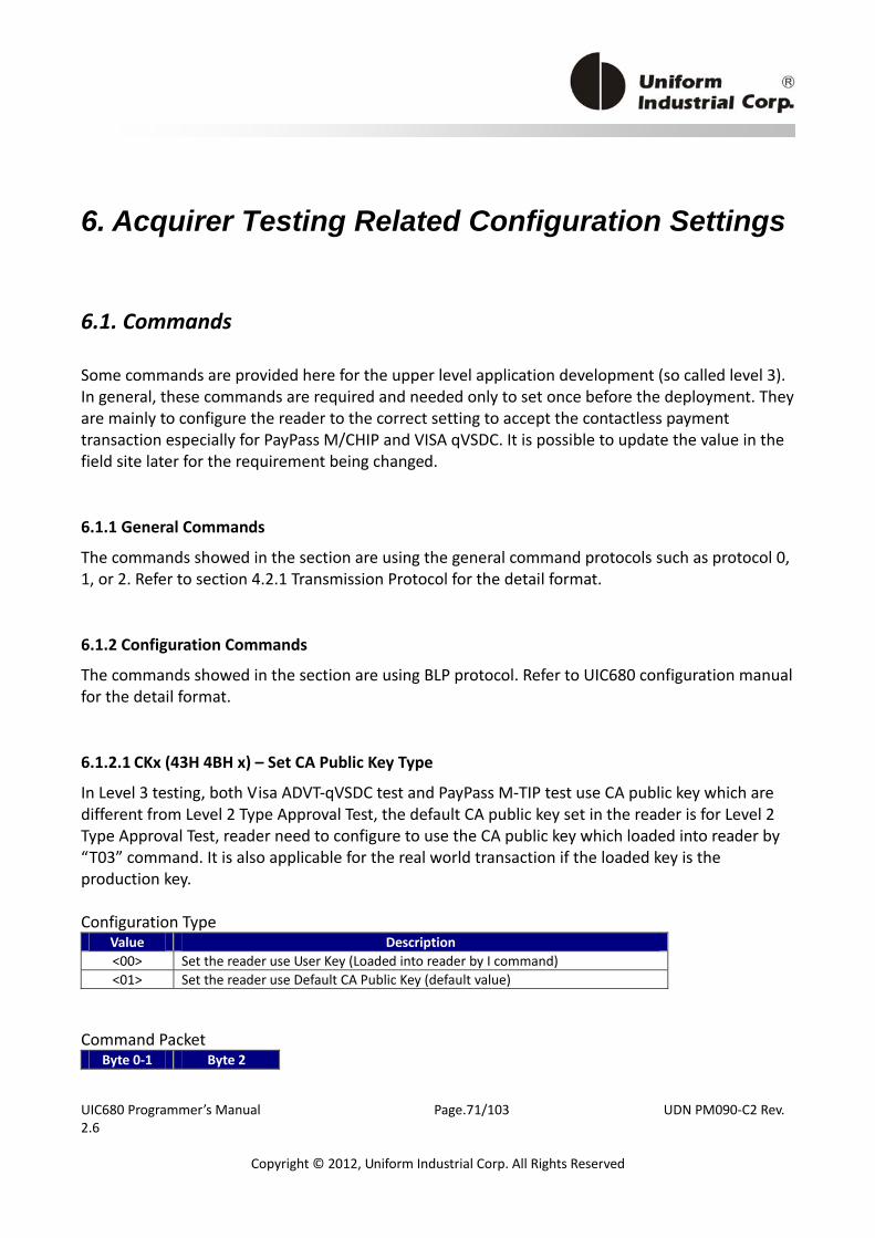
UIC680 Programmer’s Manual Page.71/103 UDN PM090‐C2 Rev. 2.6
Copyright © 2012, Uniform Industrial Corp. All Rights Reserved
6. Acquirer Testing Related Configuration Settings
6.1. Commands
Some commands are provided here for the upper level application development (so called level 3). In general, these commands are required and needed only to set once before the deployment. They are mainly to configure the reader to the correct setting to accept the contactless payment transaction especially for PayPass M/CHIP and VISA qVSDC. It is possible to update the value in the field site later for the requirement being changed.
6.1.1 General Commands
The commands showed in the section are using the general command protocols such as protocol 0, 1, or 2. Refer to section 4.2.1 Transmission Protocol for the detail format.
6.1.2 Configuration Commands
The commands showed in the section are using BLP protocol. Refer to UIC680 configuration manual for the detail format.
6.1.2.1 CKx (43H 4BH x) – Set CA Public Key Type In Level 3 testing, both Visa ADVT‐qVSDC test and PayPass M‐TIP test use CA public key which are different from Level 2 Type Approval Test, the default CA public key set in the reader is for Level 2 Type Approval Test, reader need to configure to use the CA public key which loaded into reader by “T03” command. It is also applicable for the real world transaction if the loaded key is the production key. Configuration Type
Value Description <00> Set the reader use User Key (Loaded into reader by I command) <01> Set the reader use Default CA Public Key (default value)
Command Packet Byte 0‐1 Byte 2

UIC680 Programmer’s Manual Page.72/103 UDN PM090‐C2 Rev. 2.6
Copyright © 2012, Uniform Industrial Corp. All Rights Reserved
CK Value
6.1.2.2 AD0 (41H 44D 30H x) – Set AID Type The specific AID file for Contactless testing need to be loaded by “T15” command, the default setting of reader is configure to use default AID setting, for Level 3 testing, the reader need to configure to use user defined AID. Note: user shall set T01 to setup terminal configuration and set T15 to setup contactless application configuration while using AD0<00>.
Configuration Type Value Description <00> Set the reader use User defined AID (Loaded into reader by T15 command) <31> Set the reader use Default AID. (Default value)
Command Packet Byte 0‐2 Byte 3 AD0 Value
6.1.2.3 VVx (56H 56H x) – Set Visa polling mode
The default setting of UIC680 is support MSD1.4.2 and VCPS 2.1 at the same time, but during the test session of ADVT‐qVSDC testing, test case 19 to 28 need to terminate if DDA not perform or error by the card, if the bezel support MSD1.4.2, then the bezel will output track 1 and track 2 data to make transaction go online, this command is in purpose to configure the bezel to support VCPS 2.1 only.
Configuration Type Value Description <02> Visa auto polling mode (Support both MSD 1.4.2 and VCPS 2.1) <03> Support VCPS 2.1 only
Command Packet Byte 0‐1 Byte 2
VV Value
6.1.2.4 UTx (55H 54H x) – Set TAC The command is dedicated for PayPass. The appropriate parameters please refer to specifications below: PayPass TIP PayPass – M/Chip Application Note #17, Page.8, Table 3.2 Note: This command is valid in the Self‐Arm Mode or Arm to Read. For new TLV commands (C8h) shall set in the Terminal Configuration (T01) or Contactless Application Configuration (T15).
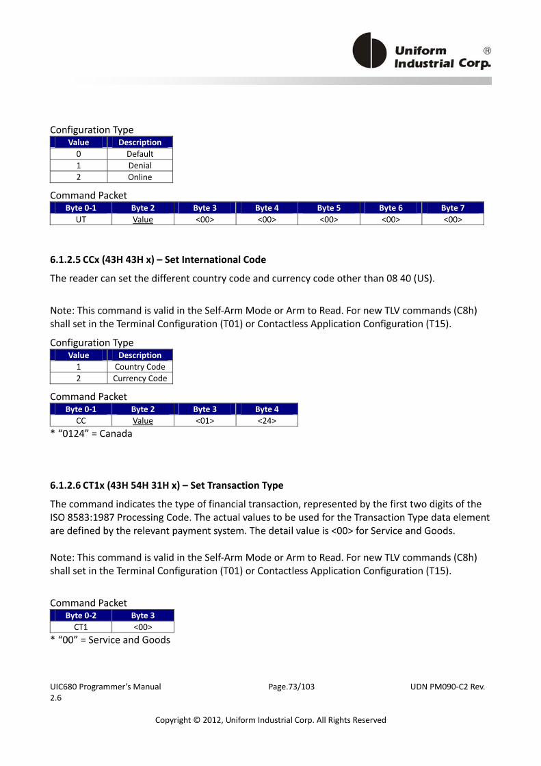
UIC680 Programmer’s Manual Page.73/103 UDN PM090‐C2 Rev. 2.6
Copyright © 2012, Uniform Industrial Corp. All Rights Reserved
Configuration Type Value Description 0 Default 1 Denial 2 Online
Command Packet Byte 0‐1 Byte 2 Byte 3 Byte 4 Byte 5 Byte 6 Byte 7
UT Value <00> <00> <00> <00> <00>
6.1.2.5 CCx (43H 43H x) – Set International Code The reader can set the different country code and currency code other than 08 40 (US).
Note: This command is valid in the Self‐Arm Mode or Arm to Read. For new TLV commands (C8h) shall set in the Terminal Configuration (T01) or Contactless Application Configuration (T15).
Configuration Type Value Description 1 Country Code2 Currency Code
Command Packet Byte 0‐1 Byte 2 Byte 3 Byte 4
CC Value <01> <24> * “0124” = Canada
6.1.2.6 CT1x (43H 54H 31H x) – Set Transaction Type The command indicates the type of financial transaction, represented by the first two digits of the ISO 8583:1987 Processing Code. The actual values to be used for the Transaction Type data element are defined by the relevant payment system. The detail value is <00> for Service and Goods. Note: This command is valid in the Self‐Arm Mode or Arm to Read. For new TLV commands (C8h) shall set in the Terminal Configuration (T01) or Contactless Application Configuration (T15).
Command Packet Byte 0‐2 Byte 3 CT1 <00>
* “00” = Service and Goods
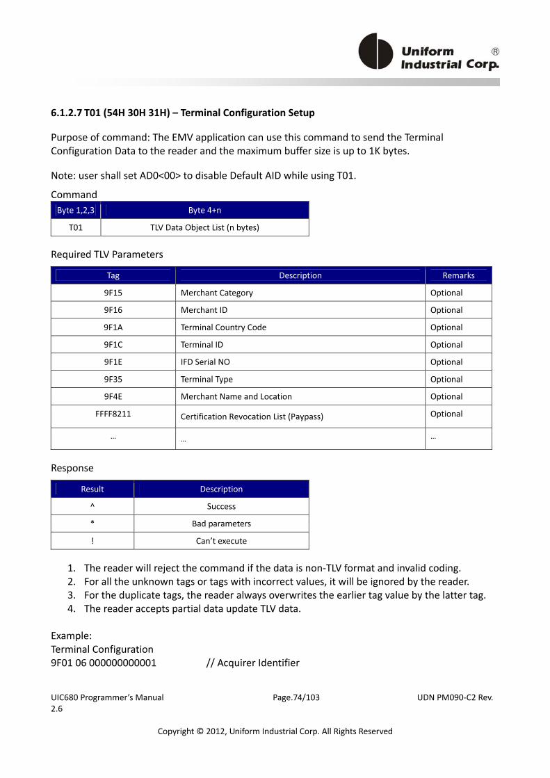
UIC680 Programmer’s Manual Page.74/103 UDN PM090‐C2 Rev. 2.6
Copyright © 2012, Uniform Industrial Corp. All Rights Reserved
6.1.2.7 T01 (54H 30H 31H) – Terminal Configuration Setup
Purpose of command: The EMV application can use this command to send the Terminal Configuration Data to the reader and the maximum buffer size is up to 1K bytes.
Note: user shall set AD0<00> to disable Default AID while using T01.
Command Byte 1,2,3 Byte 4+n
T01 TLV Data Object List (n bytes)
Required TLV Parameters
Tag Description Remarks
9F15 Merchant Category Optional
9F16 Merchant ID Optional
9F1A Terminal Country Code Optional
9F1C Terminal ID Optional
9F1E IFD Serial NO Optional
9F35 Terminal Type Optional
9F4E Merchant Name and Location Optional
FFFF8211 Certification Revocation List (Paypass) Optional
… … …
Response
Result Description
^ Success
* Bad parameters
! Can’t execute
1. The reader will reject the command if the data is non‐TLV format and invalid coding. 2. For all the unknown tags or tags with incorrect values, it will be ignored by the reader. 3. For the duplicate tags, the reader always overwrites the earlier tag value by the latter tag. 4. The reader accepts partial data update TLV data.
Example: Terminal Configuration 9F01 06 000000000001 // Acquirer Identifier
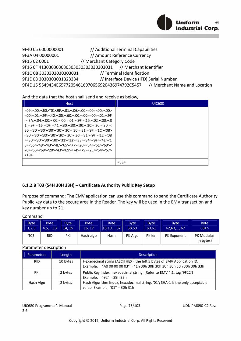
UIC680 Programmer’s Manual Page.75/103 UDN PM090‐C2 Rev. 2.6
Copyright © 2012, Uniform Industrial Corp. All Rights Reserved
9F40 05 6000000001 // Additional Terminal Capabilities 9F3A 04 00000001 // Amount Reference Currency 9F15 02 0001 // Merchant Category Code 9F16 0F 413030303030303030303030303031 // Merchant Identifier 9F1C 08 3030303030303031 // Terminal Identification 9F1E 08 3030303031323334 // Interface Device (IFD) Serial Number 9F4E 15 5549434E65772054616970656920436974792C5457 // Merchant Name and Location And the data that the host shall send and receive as below,
Host UIC680
<09><00><60>T01<9F><01><06><00><00><00><00><00><01><9F><40><05><60><00><00><00><01><9F><3A><04><00><00><00><01><9F><15><02><00><01><9F><16><0F><41><30><30><30><30><30><30><30><30><30><30><30><30><30><31><9F><1C><08><30><30><30><30><30><30><30><31><9F><1E><08><30><30><30><30><31><32><33><34><9F><4E><15><55><49><43><4E><65><77><20><54><61><69><70><65><69><20><43><69><74><79><2C><54><57><19>
<5E>
6.1.2.8 T03 (54H 30H 33H) – Certificate Authority Public Key Setup
Purpose of command: The EMV application can use this command to send the Certificate Authority Public key data to the secure area in the Reader. The key will be used in the EMV transaction and key number up to 21.
Command Byte 1,2,3
Byte 4,5,…,13
Byte 14, 15
Byte 16, 17
Byte 18,19,…,57
Byte 58,59
Byte 60,61
Byte 62,63,…, 67
Byte 68+n
T03 RID PKI Hash algo Hash PK Algo PK len PK Exponent PK Modulus (n bytes)
Parameter description Parameters Length Description
RID 10 bytes Hexadecimal string (ASCII HEX), the left 5 bytes of EMV Application ID. Example. “A0 00 00 00 03” = 41h 30h 30h 30h 30h 30h 30h 30h 30h 33h
PKI 2 bytes Public Key Index, hexadecimal string. (Refer to EMV 4.1, tag ‘9F22’) Example, ”92” = 39h 32h
Hash Algo 2 bytes Hash Algorithm Index, hexadecimal string. ‘01’: SHA‐1 is the only acceptable value. Example, “01” = 30h 31h
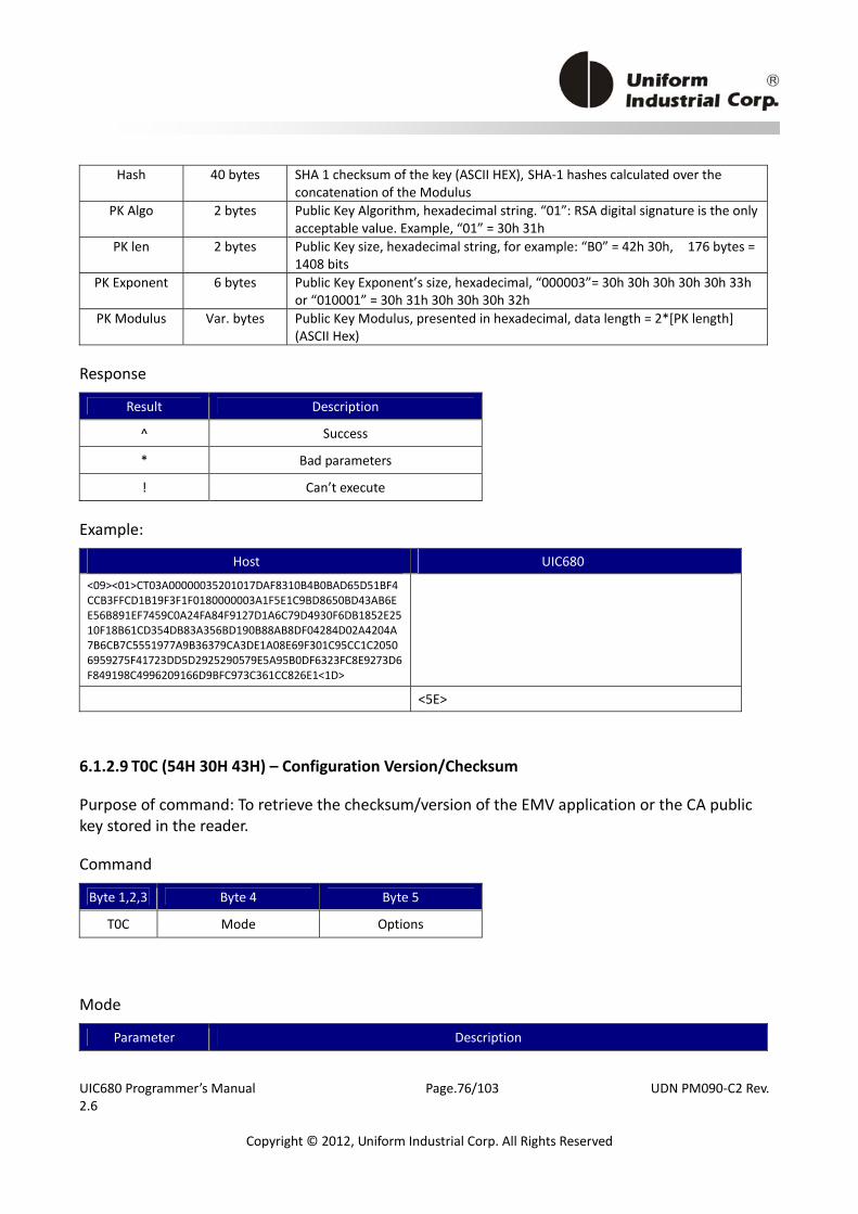
UIC680 Programmer’s Manual Page.76/103 UDN PM090‐C2 Rev. 2.6
Copyright © 2012, Uniform Industrial Corp. All Rights Reserved
Hash 40 bytes SHA 1 checksum of the key (ASCII HEX), SHA‐1 hashes calculated over the concatenation of the Modulus
PK Algo 2 bytes Public Key Algorithm, hexadecimal string. “01”: RSA digital signature is the only acceptable value. Example, “01” = 30h 31h
PK len 2 bytes Public Key size, hexadecimal string, for example: “B0” = 42h 30h, 176 bytes = 1408 bits
PK Exponent 6 bytes Public Key Exponent’s size, hexadecimal, “000003”= 30h 30h 30h 30h 30h 33h or “010001” = 30h 31h 30h 30h 30h 32h
PK Modulus Var. bytes Public Key Modulus, presented in hexadecimal, data length = 2*[PK length] (ASCII Hex)
Response
Result Description
^ Success
* Bad parameters
! Can’t execute
Example:
Host UIC680
<09><01>CT03A00000035201017DAF8310B4B0BAD65D51BF4CCB3FFCD1B19F3F1F0180000003A1F5E1C9BD8650BD43AB6EE56B891EF7459C0A24FA84F9127D1A6C79D4930F6DB1852E2510F18B61CD354DB83A356BD190B88AB8DF04284D02A4204A7B6CB7C5551977A9B36379CA3DE1A08E69F301C95CC1C20506959275F41723DD5D2925290579E5A95B0DF6323FC8E9273D6F849198C4996209166D9BFC973C361CC826E1<1D>
<5E>
6.1.2.9 T0C (54H 30H 43H) – Configuration Version/Checksum
Purpose of command: To retrieve the checksum/version of the EMV application or the CA public key stored in the reader.
Command
Byte 1,2,3 Byte 4 Byte 5
T0C Mode Options
Mode
Parameter Description
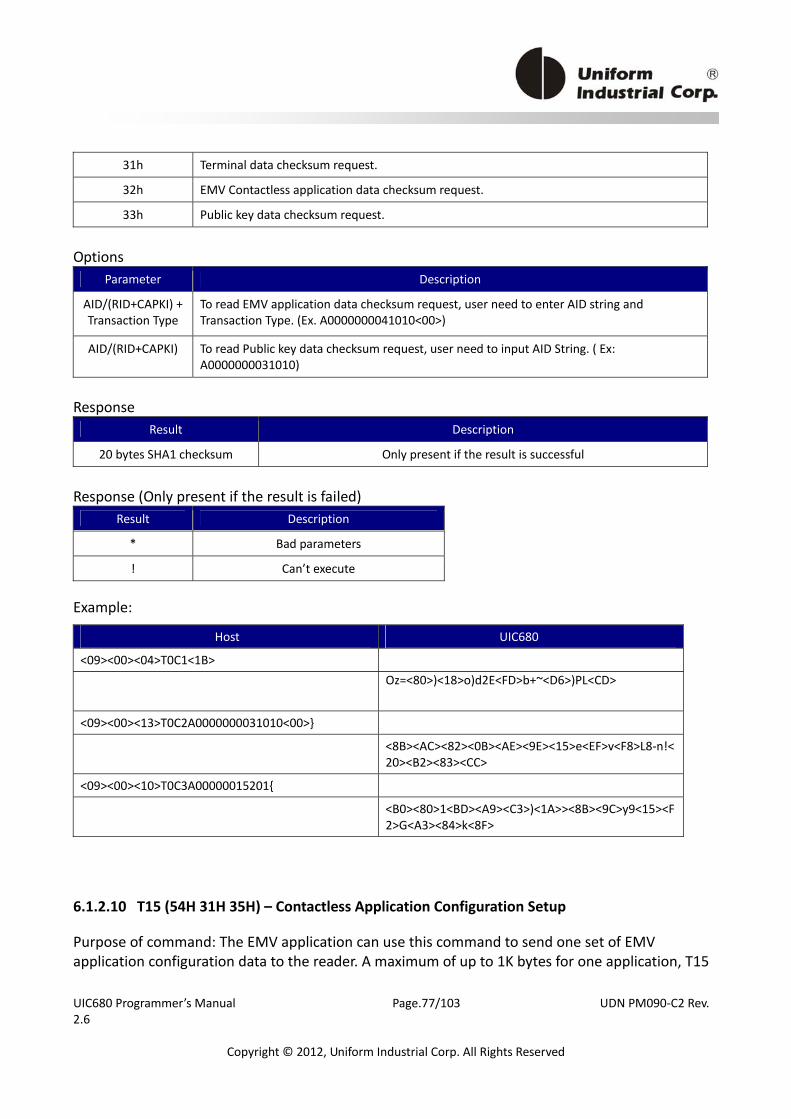
UIC680 Programmer’s Manual Page.77/103 UDN PM090‐C2 Rev. 2.6
Copyright © 2012, Uniform Industrial Corp. All Rights Reserved
31h Terminal data checksum request.
32h EMV Contactless application data checksum request.
33h Public key data checksum request.
Options
Parameter Description
AID/(RID+CAPKI) + Transaction Type
To read EMV application data checksum request, user need to enter AID string and Transaction Type. (Ex. A0000000041010<00>)
AID/(RID+CAPKI) To read Public key data checksum request, user need to input AID String. ( Ex: A0000000031010)
Response
Result Description
20 bytes SHA1 checksum Only present if the result is successful
Response (Only present if the result is failed)
Result Description
* Bad parameters
! Can’t execute
Example:
Host UIC680
<09><00><04>T0C1<1B>
Oz=<80>)<18>o)d2E<FD>b+~<D6>)PL<CD>
<09><00><13>T0C2A0000000031010<00>}
<8B><AC><82><0B><AE><9E><15>e<EF>v<F8>L8‐n!<20><B2><83><CC>
<09><00><10>T0C3A00000015201{
<B0><80>1<BD><A9><C3>)<1A>><8B><9C>y9<15><F2>G<A3><84>k<8F>
6.1.2.10 T15 (54H 31H 35H) – Contactless Application Configuration Setup
Purpose of command: The EMV application can use this command to send one set of EMV application configuration data to the reader. A maximum of up to 1K bytes for one application, T15
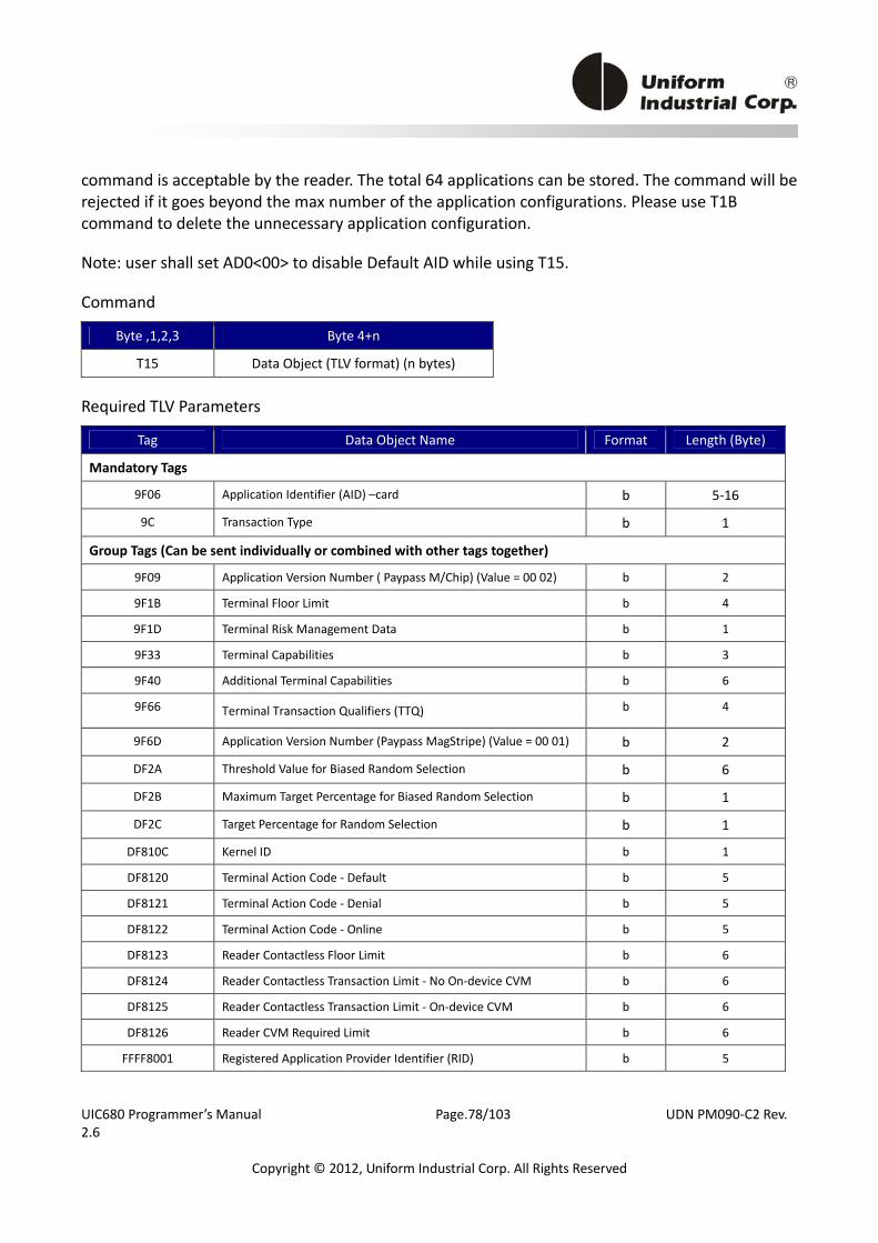
UIC680 Programmer’s Manual Page.78/103 UDN PM090‐C2 Rev. 2.6
Copyright © 2012, Uniform Industrial Corp. All Rights Reserved
command is acceptable by the reader. The total 64 applications can be stored. The command will be rejected if it goes beyond the max number of the application configurations. Please use T1B command to delete the unnecessary application configuration.
Note: user shall set AD0<00> to disable Default AID while using T15.
Command
Byte ,1,2,3 Byte 4+n
T15 Data Object (TLV format) (n bytes)
Required TLV Parameters
Tag Data Object Name Format Length (Byte)
Mandatory Tags
9F06 Application Identifier (AID) –card b 5‐16
9C Transaction Type b 1
Group Tags (Can be sent individually or combined with other tags together)
9F09 Application Version Number ( Paypass M/Chip) (Value = 00 02) b 2
9F1B Terminal Floor Limit b 4
9F1D Terminal Risk Management Data b 1
9F33 Terminal Capabilities b 3
9F40 Additional Terminal Capabilities b 6
9F66 Terminal Transaction Qualifiers (TTQ) b 4
9F6D Application Version Number (Paypass MagStripe) (Value = 00 01) b 2
DF2A Threshold Value for Biased Random Selection b 6
DF2B Maximum Target Percentage for Biased Random Selection b 1
DF2C Target Percentage for Random Selection b 1
DF810C Kernel ID b 1
DF8120 Terminal Action Code ‐ Default b 5
DF8121 Terminal Action Code ‐ Denial b 5
DF8122 Terminal Action Code ‐ Online b 5
DF8123 Reader Contactless Floor Limit b 6
DF8124 Reader Contactless Transaction Limit ‐ No On‐device CVM b 6
DF8125 Reader Contactless Transaction Limit ‐ On‐device CVM b 6
DF8126 Reader CVM Required Limit b 6
FFFF8001 Registered Application Provider Identifier (RID) b 5
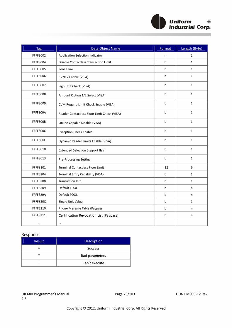
UIC680 Programmer’s Manual Page.79/103 UDN PM090‐C2 Rev. 2.6
Copyright © 2012, Uniform Industrial Corp. All Rights Reserved
Tag Data Object Name Format Length (Byte)
FFFF8002 Application Selection Indicator n 1
FFFF8004 Disable Contactless Transaction Limit b 1
FFFF8005 Zero allow b 1
FFFF8006 CVN17 Enable (VISA) b 1
FFFF8007 Sign Unit Check (VISA) b 1
FFFF8008 Amount Option 1/2 Select (VISA) b 1
FFFF8009 CVM Require Limit Check Enable (VISA) b 1
FFFF800A Reader Contactless Floor Limit Check (VISA) b 1
FFFF800B Online Capable Disable (VISA) b 1
FFFF800C Exception Check Enable b 1
FFFF800F Dynamic Reader Limits Enable (VISA) b 1
FFFF8010 Extended Selection Support flag b 1
FFFF8013 Pre‐Processing Setting b 1
FFFF8101 Terminal Contactless Floor Limit n12 6
FFFF8204 Terminal Entry Capability (VISA) b 1
FFFF8208 Transaction Info b 1
FFFF8209 Default TDOL b n
FFFF820A Default PDOL b n
FFFF820C Single Unit Value b 1
FFFF8210 Phone Message Table (Paypass) b n
FFFF8211 Certification Revocation List (Paypass) b n
… …
Response
Result Description
^ Success
* Bad parameters
! Can’t execute
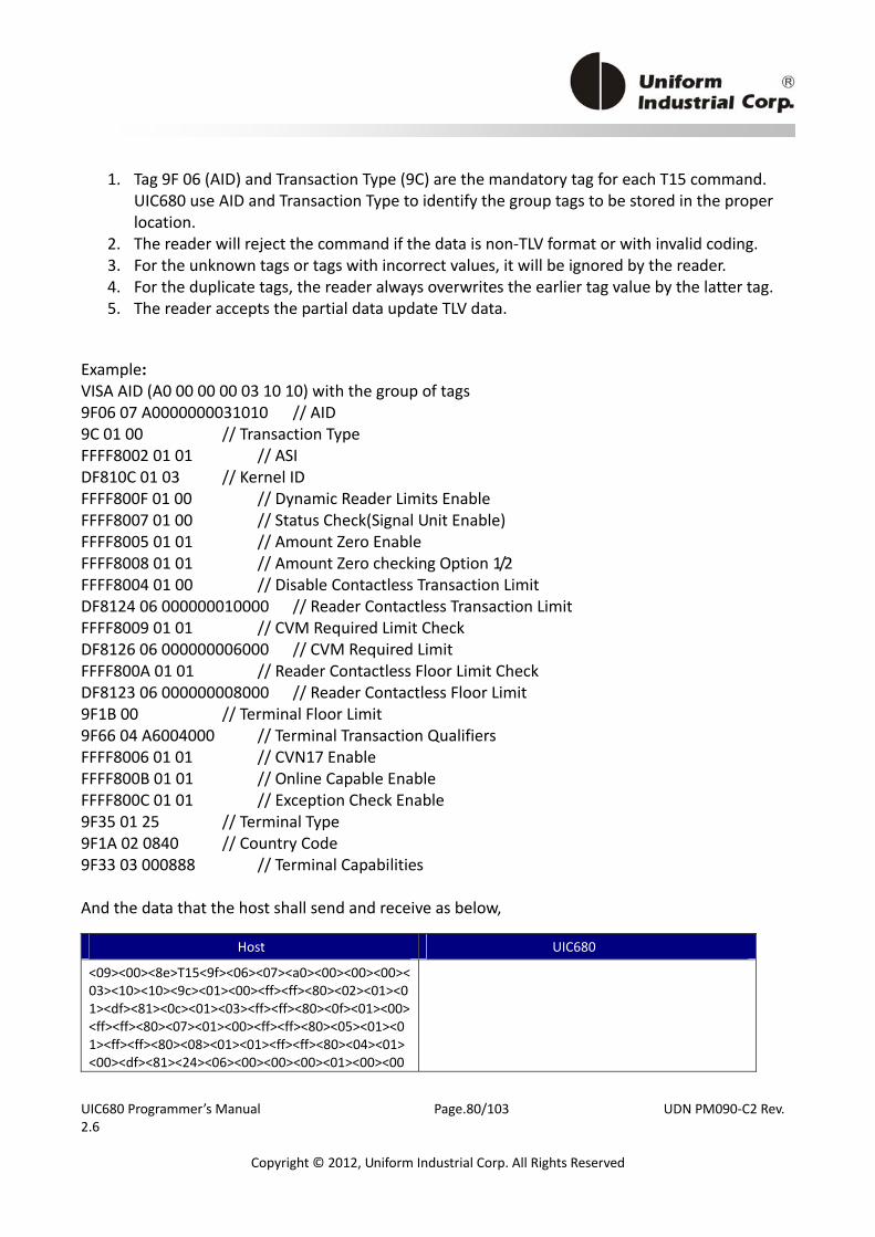
UIC680 Programmer’s Manual Page.80/103 UDN PM090‐C2 Rev. 2.6
Copyright © 2012, Uniform Industrial Corp. All Rights Reserved
1. Tag 9F 06 (AID) and Transaction Type (9C) are the mandatory tag for each T15 command. UIC680 use AID and Transaction Type to identify the group tags to be stored in the proper location.
2. The reader will reject the command if the data is non‐TLV format or with invalid coding. 3. For the unknown tags or tags with incorrect values, it will be ignored by the reader. 4. For the duplicate tags, the reader always overwrites the earlier tag value by the latter tag. 5. The reader accepts the partial data update TLV data.
Example: VISA AID (A0 00 00 00 03 10 10) with the group of tags 9F06 07 A0000000031010 // AID 9C 01 00 // Transaction Type FFFF8002 01 01 // ASI DF810C 01 03 // Kernel ID FFFF800F 01 00 // Dynamic Reader Limits Enable FFFF8007 01 00 // Status Check(Signal Unit Enable) FFFF8005 01 01 // Amount Zero Enable FFFF8008 01 01 // Amount Zero checking Option 1/2 FFFF8004 01 00 // Disable Contactless Transaction Limit DF8124 06 000000010000 // Reader Contactless Transaction Limit FFFF8009 01 01 // CVM Required Limit Check DF8126 06 000000006000 // CVM Required Limit FFFF800A 01 01 // Reader Contactless Floor Limit Check DF8123 06 000000008000 // Reader Contactless Floor Limit 9F1B 00 // Terminal Floor Limit 9F66 04 A6004000 // Terminal Transaction Qualifiers FFFF8006 01 01 // CVN17 Enable FFFF800B 01 01 // Online Capable Enable FFFF800C 01 01 // Exception Check Enable 9F35 01 25 // Terminal Type 9F1A 02 0840 // Country Code 9F33 03 000888 // Terminal Capabilities And the data that the host shall send and receive as below,
Host UIC680
<09><00><8e>T15<9f><06><07><a0><00><00><00><03><10><10><9c><01><00><ff><ff><80><02><01><01><df><81><0c><01><03><ff><ff><80><0f><01><00><ff><ff><80><07><01><00><ff><ff><80><05><01><01><ff><ff><80><08><01><01><ff><ff><80><04><01><00><df><81><24><06><00><00><00><01><00><00
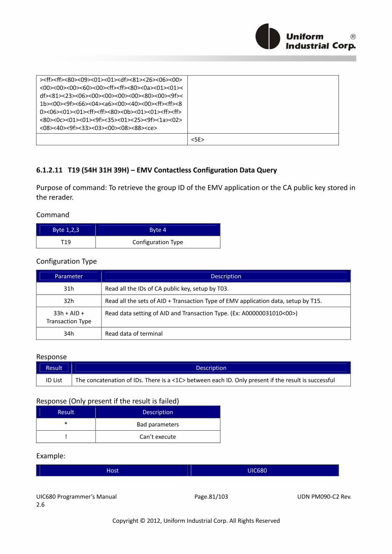
UIC680 Programmer’s Manual Page.81/103 UDN PM090‐C2 Rev. 2.6
Copyright © 2012, Uniform Industrial Corp. All Rights Reserved
><ff><ff><80><09><01><01><df><81><26><06><00><00><00><00><60><00><ff><ff><80><0a><01><01><df><81><23><06><00><00><00><00><80><00><9f><1b><00><9f><66><04><a6><00><40><00><ff><ff><80><06><01><01><ff><ff><80><0b><01><01><ff><ff><80><0c><01><01><9f><35><01><25><9f><1a><02><08><40><9f><33><03><00><08><88><ce>
<5E>
6.1.2.11 T19 (54H 31H 39H) – EMV Contactless Configuration Data Query
Purpose of command: To retrieve the group ID of the EMV application or the CA public key stored in the rerader.
Command
Byte 1,2,3 Byte 4
T19 Configuration Type
Configuration Type
Parameter Description
31h Read all the IDs of CA public key, setup by T03.
32h Read all the sets of AID + Transaction Type of EMV application data, setup by T15.
33h + AID + Transaction Type
Read data setting of AID and Transaction Type. (Ex: A00000031010<00>)
34h Read data of terminal
Response
Result Description
ID List The concatenation of IDs. There is a <1C> between each ID. Only present if the result is successful
Response (Only present if the result is failed)
Result Description
* Bad parameters
! Can’t execute
Example:
Host UIC680
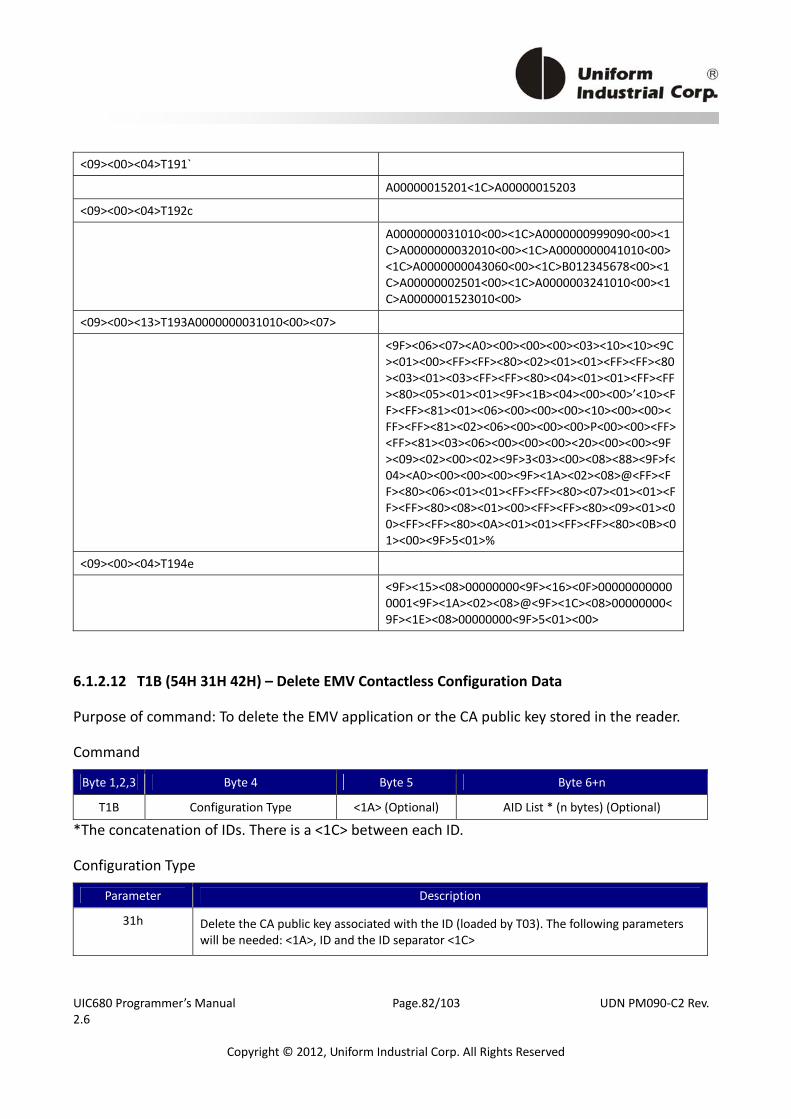
UIC680 Programmer’s Manual Page.82/103 UDN PM090‐C2 Rev. 2.6
Copyright © 2012, Uniform Industrial Corp. All Rights Reserved
<09><00><04>T191`
A00000015201<1C>A00000015203
<09><00><04>T192c
A0000000031010<00><1C>A0000000999090<00><1C>A0000000032010<00><1C>A0000000041010<00><1C>A0000000043060<00><1C>B012345678<00><1C>A00000002501<00><1C>A0000003241010<00><1C>A0000001523010<00>
<09><00><13>T193A0000000031010<00><07>
<9F><06><07><A0><00><00><00><03><10><10><9C><01><00><FF><FF><80><02><01><01><FF><FF><80><03><01><03><FF><FF><80><04><01><01><FF><FF><80><05><01><01><9F><1B><04><00><00>’<10><FF><FF><81><01><06><00><00><00><10><00><00><FF><FF><81><02><06><00><00><00>P<00><00><FF><FF><81><03><06><00><00><00><20><00><00><9F><09><02><00><02><9F>3<03><00><08><88><9F>f<04><A0><00><00><00><9F><1A><02><08>@<FF><FF><80><06><01><01><FF><FF><80><07><01><01><FF><FF><80><08><01><00><FF><FF><80><09><01><00><FF><FF><80><0A><01><01><FF><FF><80><0B><01><00><9F>5<01>%
<09><00><04>T194e
<9F><15><08>00000000<9F><16><0F>000000000000001<9F><1A><02><08>@<9F><1C><08>00000000<9F><1E><08>00000000<9F>5<01><00>
6.1.2.12 T1B (54H 31H 42H) – Delete EMV Contactless Configuration Data
Purpose of command: To delete the EMV application or the CA public key stored in the reader.
Command
Byte 1,2,3 Byte 4 Byte 5 Byte 6+n
T1B Configuration Type <1A> (Optional) AID List * (n bytes) (Optional)
*The concatenation of IDs. There is a <1C> between each ID.
Configuration Type
Parameter Description
31h Delete the CA public key associated with the ID (loaded by T03). The following parameters will be needed: <1A>, ID and the ID separator <1C>

UIC680 Programmer’s Manual Page.83/103 UDN PM090‐C2 Rev. 2.6
Copyright © 2012, Uniform Industrial Corp. All Rights Reserved
32h Delete the application data associated with the ID (loaded by T15). The following parameters will be needed: <1A>, ID and the ID separator <1C>
33h Delete all CA public keys.
34h Delete all EMV application data.
35h Delete Terminal Setting.
36h Reserved
37h Reserved
Response
Result Description
^ Success
* Bad parameters
! Can’t execute Example: Assuming there is a key ID = A00000000392
Host UIC680
<09><00><04>T191`
A00000000392 Delete key ID A00000000392
Host UIC680
<09><00><12>T1B1<1A>A00000000392<1C>r
^ Assuming there are two application files ‐ A0000000031010 and A0000000041010
Host UIC680
<09><00><04>T192c
A0000000031010<1C>A0000000041010 Delete 2 applications files
Host UIC680
<09><00>#T1B2<1A>A0000000031010<1C>A0000000041010<1C>"
^
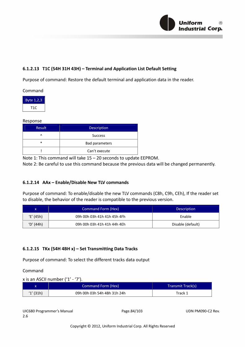
UIC680 Programmer’s Manual Page.84/103 UDN PM090‐C2 Rev. 2.6
Copyright © 2012, Uniform Industrial Corp. All Rights Reserved
6.1.2.13 T1C (54H 31H 43H) – Terminal and Application List Default Setting
Purpose of command: Restore the default terminal and application data in the reader.
Command
Byte 1,2,3
T1C
Response
Result Description
^ Success
* Bad parameters
! Can’t execute
Note 1: This command will take 15 – 20 seconds to update EEPROM. Note 2: Be careful to use this command because the previous data will be changed permanently.
6.1.2.14 AAx – Enable/Disable New TLV commands
Purpose of command: To enable/disable the new TLV commands (C8h, C9h, CEh), If the reader set to disable, the behavior of the reader is compatible to the previous version.
x Command Form (Hex) Description
‘E’ (45h) 09h 00h 03h 41h 41h 45h 4Fh Enable
‘D’ (44h) 09h 00h 03h 41h 41h 44h 4Eh Disable (default)
6.1.2.15 TKx (54H 4BH x) – Set Transmitting Data Tracks
Purpose of command: To select the different tracks data output
Command
x is an ASCII number (‘1’ ‐ ‘7’). x Command Form (Hex) Transmit Track(s)
‘1’ (31h) 09h 00h 03h 54h 4Bh 31h 24h Track 1
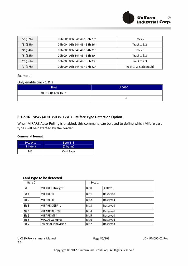
UIC680 Programmer’s Manual Page.85/103 UDN PM090‐C2 Rev. 2.6
Copyright © 2012, Uniform Industrial Corp. All Rights Reserved
‘2’ (32h) 09h 00h 03h 54h 4Bh 32h 27h Track 2
‘3’ (33h) 09h 00h 03h 54h 4Bh 33h 26h Track 1 & 2
‘4’ (34h) 09h 00h 03h 54h 4Bh 34h 21h Track 3
‘5’ (35h) 09h 00h 03h 54h 4Bh 35h 20h Track 1 & 3
‘6’ (36h) 09h 00h 03h 54h 4Bh 36h 23h Track 2 & 3
‘7’ (37h) 09h 00h 03h 54h 4Bh 37h 22h Track 1, 2 & 3(default)
Example:
Only enable track 1 & 2 Host UIC680
<09><00><03>TK3&
^
6.1.2.16 M5xx (4DH 35H xxH xxH) – Mifare Type Detection Option
When MIFARE Auto‐Polling is enabled, this command can be used to define which Mifare card types will be detected by the reader.
Command format
Byte 0~1 (2 bytes)
Byte 2~3 (2 bytes)
M5 Card Type
Card type to be detected Byte 0 Byte 1
Bit 0 MIFARE Ultralight Bit 0 JCOP31
Bit 1 MIFARE 1K Bit 1 Reserved
Bit 2 MIFARE 4k Bit 2 Reserved
Bit 3 MIFARE DESFire Bit 3 Reserved
Bit 4 MIFARE Plus 2K Bit 4 Reserved Bit 5 MIFARE Mini Bit 5 Reserved Bit 6 MPCOS Gemplus Bit 6 Reserved Bit 7 Jewel for Innovision Bit 7 Reserved
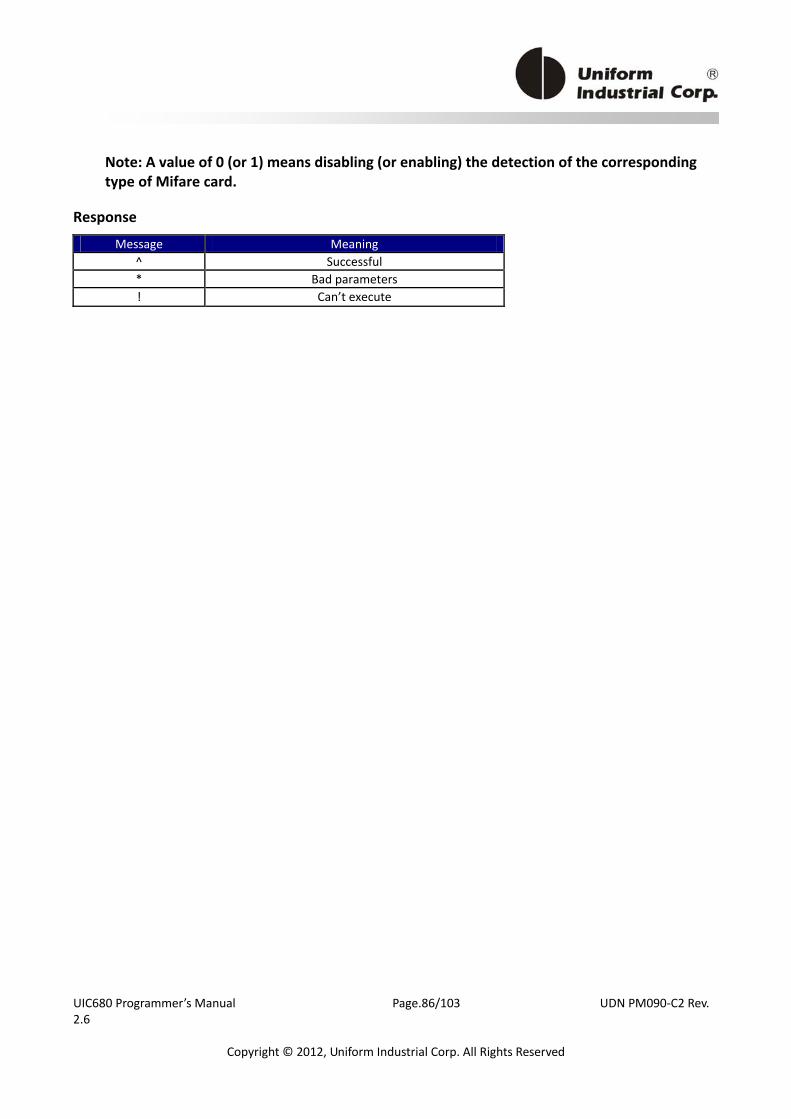
UIC680 Programmer’s Manual Page.86/103 UDN PM090‐C2 Rev. 2.6
Copyright © 2012, Uniform Industrial Corp. All Rights Reserved
Note: A value of 0 (or 1) means disabling (or enabling) the detection of the corresponding type of Mifare card.
Response
Message Meaning ^ Successful * Bad parameters ! Can’t execute
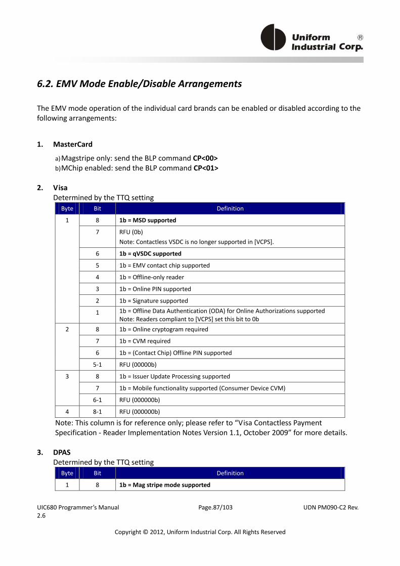
UIC680 Programmer’s Manual Page.87/103 UDN PM090‐C2 Rev. 2.6
Copyright © 2012, Uniform Industrial Corp. All Rights Reserved
6.2. EMV Mode Enable/Disable Arrangements
The EMV mode operation of the individual card brands can be enabled or disabled according to the following arrangements:
1. MasterCard
a) Magstripe only: send the BLP command CP<00> b) MChip enabled: send the BLP command CP<01>
2. Visa
Determined by the TTQ setting Byte Bit Definition
8 1b = MSD supported
7 RFU (0b) Note: Contactless VSDC is no longer supported in [VCPS].
6 1b = qVSDC supported
5 1b = EMV contact chip supported 4 1b = Offline‐only reader 3 1b = Online PIN supported 2 1b = Signature supported
1
1 1b = Offline Data Authentication (ODA) for Online Authorizations supported Note: Readers compliant to [VCPS] set this bit to 0b
8 1b = Online cryptogram required 7 1b = CVM required 6 1b = (Contact Chip) Offline PIN supported
2
5‐1 RFU (00000b) 8 1b = Issuer Update Processing supported 7 1b = Mobile functionality supported (Consumer Device CVM)
3
6‐1 RFU (000000b) 4 8‐1 RFU (000000b)
Note: This column is for reference only; please refer to “Visa Contactless Payment Specification ‐ Reader Implementation Notes Version 1.1, October 2009” for more details.
3. DPAS Determined by the TTQ setting
Byte Bit Definition
1 8 1b = Mag stripe mode supported
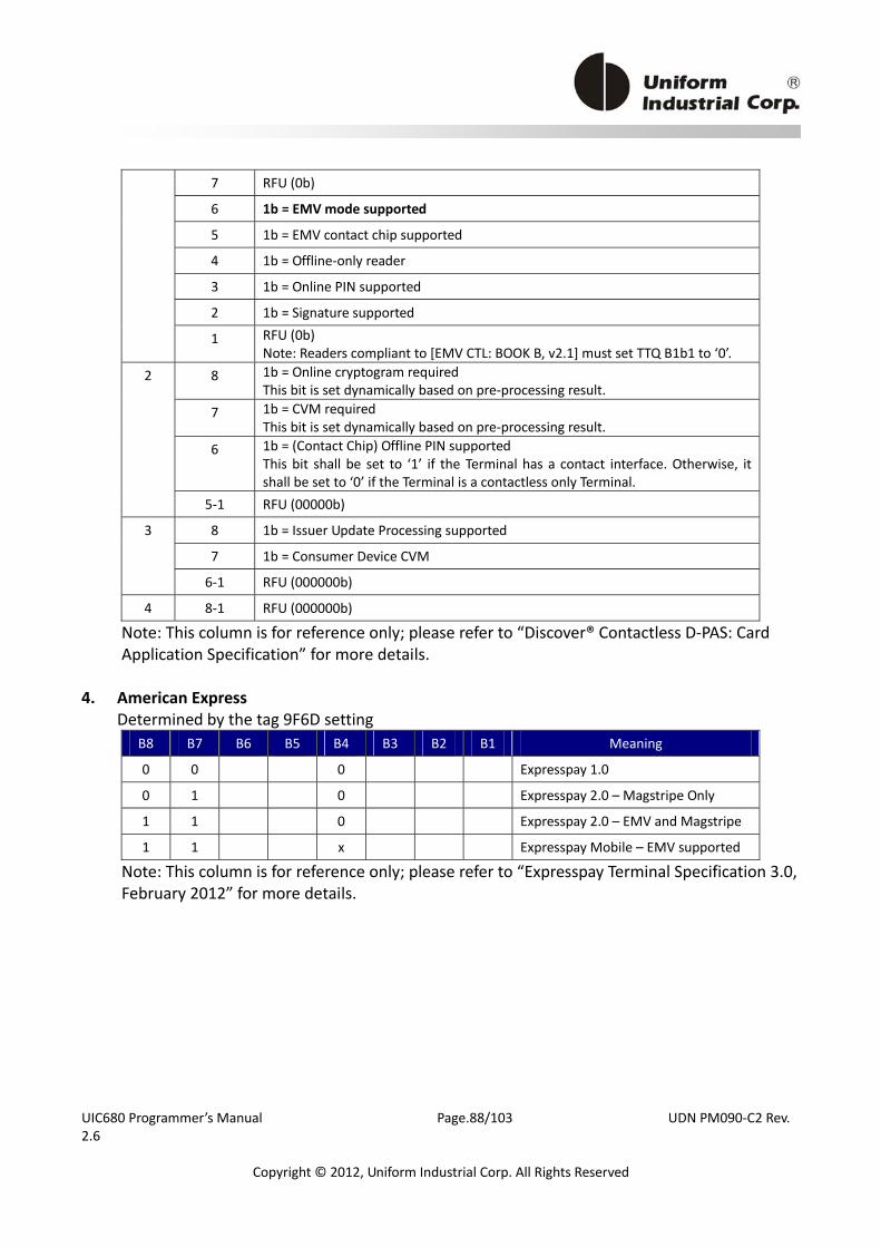
UIC680 Programmer’s Manual Page.88/103 UDN PM090‐C2 Rev. 2.6
Copyright © 2012, Uniform Industrial Corp. All Rights Reserved
7 RFU (0b)
6 1b = EMV mode supported
5 1b = EMV contact chip supported 4 1b = Offline‐only reader 3 1b = Online PIN supported 2 1b = Signature supported 1 RFU (0b)
Note: Readers compliant to [EMV CTL: BOOK B, v2.1] must set TTQ B1b1 to ‘0’. 8 1b = Online cryptogram required
This bit is set dynamically based on pre‐processing result. 7 1b = CVM required
This bit is set dynamically based on pre‐processing result. 6 1b = (Contact Chip) Offline PIN supported
This bit shall be set to ‘1’ if the Terminal has a contact interface. Otherwise, it shall be set to ‘0’ if the Terminal is a contactless only Terminal.
2
5‐1 RFU (00000b) 8 1b = Issuer Update Processing supported 7 1b = Consumer Device CVM
3
6‐1 RFU (000000b) 4 8‐1 RFU (000000b)
Note: This column is for reference only; please refer to “Discover® Contactless D‐PAS: Card Application Specification” for more details.
4. American Express Determined by the tag 9F6D setting
B8 B7 B6 B5 B4 B3 B2 B1 Meaning
0 0 0 Expresspay 1.0
0 1 0 Expresspay 2.0 – Magstripe Only
1 1 0 Expresspay 2.0 – EMV and Magstripe
1 1 x Expresspay Mobile – EMV supported
Note: This column is for reference only; please refer to “Expresspay Terminal Specification 3.0, February 2012” for more details.
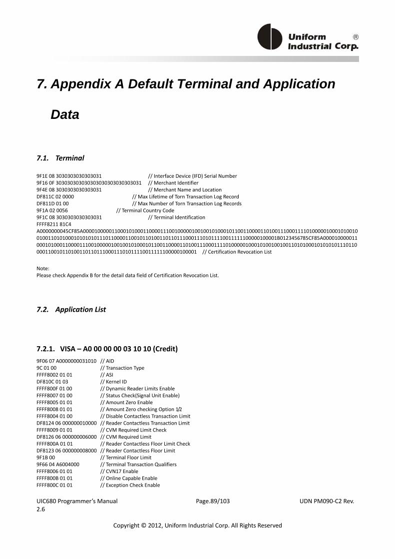
UIC680 Programmer’s Manual Page.89/103 UDN PM090‐C2 Rev. 2.6
Copyright © 2012, Uniform Industrial Corp. All Rights Reserved
7. Appendix A Default Terminal and Application
Data
7.1. Terminal
9F1E 08 3030303030303031 // Interface Device (IFD) Serial Number 9F16 0F 303030303030303030303030303031 // Merchant Identifier 9F4E 08 3030303030303031 // Merchant Name and Location DF811C 02 0000 // Max Lifetime of Torn Transaction Log Record DF811D 01 00 // Max Number of Torn Transaction Log Records 9F1A 02 0056 // Terminal Country Code 9F1C 08 3030303030303031 // Terminal Identification FFFF8211 81C4 A0000000045CF85A000010000011000101000110000111001000001001001010001011001100001101001110001111010000010001010010010011010100010101010111011000011001011010011011011100011101011110011111100000100001B0123456785CF85A000010000011000101000110000111001000001001001010001011001100001101001110001111010000010001010010010011010100010101010111011000011001011010011011011100011101011110011111100000100001 // Certification Revocation List
Note: Please check Appendix B for the detail data field of Certification Revocation List.
7.2. Application List
7.2.1. VISA – A0 00 00 00 03 10 10 (Credit) 9F06 07 A0000000031010 // AID 9C 01 00 // Transaction Type FFFF8002 01 01 // ASI DF810C 01 03 // Kernel ID FFFF800F 01 00 // Dynamic Reader Limits Enable FFFF8007 01 00 // Status Check(Signal Unit Enable) FFFF8005 01 01 // Amount Zero Enable FFFF8008 01 01 // Amount Zero checking Option 1/2 FFFF8004 01 00 // Disable Contactless Transaction Limit DF8124 06 000000010000 // Reader Contactless Transaction Limit FFFF8009 01 01 // CVM Required Limit Check DF8126 06 000000006000 // CVM Required Limit FFFF800A 01 01 // Reader Contactless Floor Limit Check DF8123 06 000000008000 // Reader Contactless Floor Limit 9F1B 00 // Terminal Floor Limit 9F66 04 A6004000 // Terminal Transaction Qualifiers FFFF8006 01 01 // CVN17 Enable FFFF800B 01 01 // Online Capable Enable FFFF800C 01 01 // Exception Check Enable
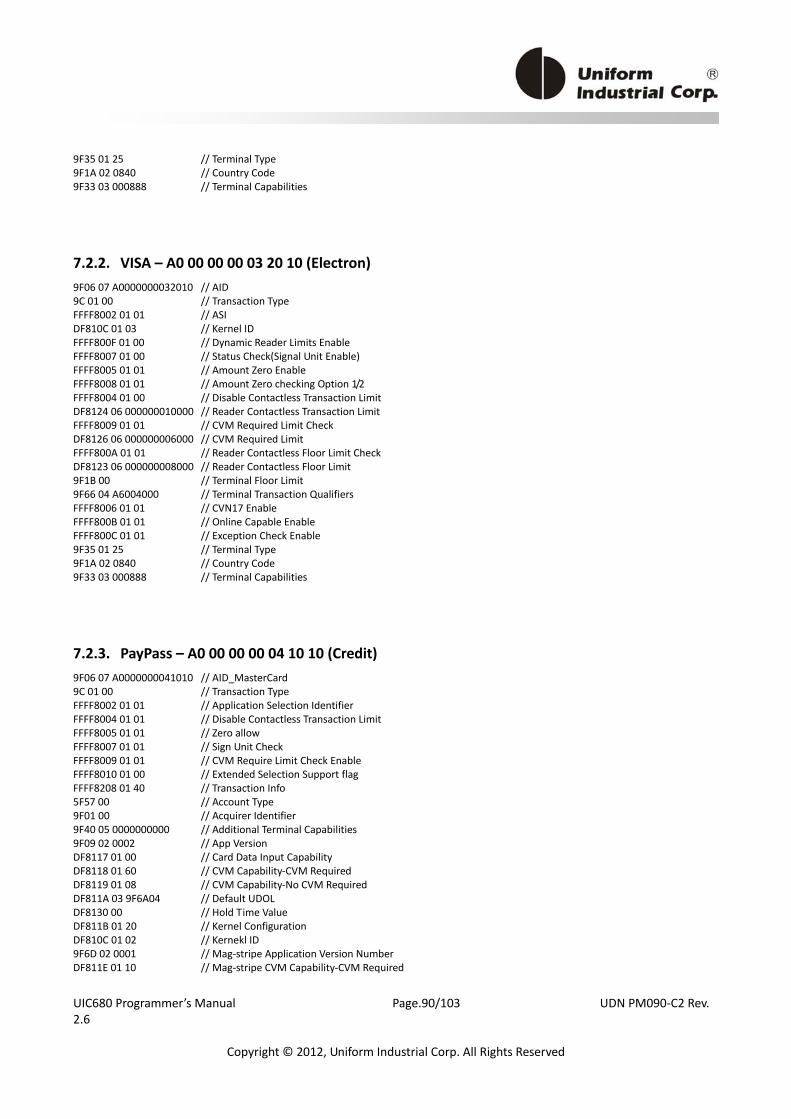
UIC680 Programmer’s Manual Page.90/103 UDN PM090‐C2 Rev. 2.6
Copyright © 2012, Uniform Industrial Corp. All Rights Reserved
9F35 01 25 // Terminal Type 9F1A 02 0840 // Country Code 9F33 03 000888 // Terminal Capabilities
7.2.2. VISA – A0 00 00 00 03 20 10 (Electron) 9F06 07 A0000000032010 // AID 9C 01 00 // Transaction Type FFFF8002 01 01 // ASI DF810C 01 03 // Kernel ID FFFF800F 01 00 // Dynamic Reader Limits Enable FFFF8007 01 00 // Status Check(Signal Unit Enable) FFFF8005 01 01 // Amount Zero Enable FFFF8008 01 01 // Amount Zero checking Option 1/2 FFFF8004 01 00 // Disable Contactless Transaction Limit DF8124 06 000000010000 // Reader Contactless Transaction Limit FFFF8009 01 01 // CVM Required Limit Check DF8126 06 000000006000 // CVM Required Limit FFFF800A 01 01 // Reader Contactless Floor Limit Check DF8123 06 000000008000 // Reader Contactless Floor Limit 9F1B 00 // Terminal Floor Limit 9F66 04 A6004000 // Terminal Transaction Qualifiers FFFF8006 01 01 // CVN17 Enable FFFF800B 01 01 // Online Capable Enable FFFF800C 01 01 // Exception Check Enable 9F35 01 25 // Terminal Type 9F1A 02 0840 // Country Code 9F33 03 000888 // Terminal Capabilities
7.2.3. PayPass – A0 00 00 00 04 10 10 (Credit) 9F06 07 A0000000041010 // AID_MasterCard 9C 01 00 // Transaction Type FFFF8002 01 01 // Application Selection Identifier FFFF8004 01 01 // Disable Contactless Transaction Limit FFFF8005 01 01 // Zero allow FFFF8007 01 01 // Sign Unit Check FFFF8009 01 01 // CVM Require Limit Check Enable FFFF8010 01 00 // Extended Selection Support flag FFFF8208 01 40 // Transaction Info 5F57 00 // Account Type 9F01 00 // Acquirer Identifier 9F40 05 0000000000 // Additional Terminal Capabilities 9F09 02 0002 // App Version DF8117 01 00 // Card Data Input Capability DF8118 01 60 // CVM Capability‐CVM Required DF8119 01 08 // CVM Capability‐No CVM Required DF811A 03 9F6A04 // Default UDOL DF8130 00 // Hold Time Value DF811B 01 20 // Kernel Configuration DF810C 01 02 // Kernekl ID 9F6D 02 0001 // Mag‐stripe Application Version Number DF811E 01 10 // Mag‐stripe CVM Capability‐CVM Required

UIC680 Programmer’s Manual Page.91/103 UDN PM090‐C2 Rev. 2.6
Copyright © 2012, Uniform Industrial Corp. All Rights Reserved
DF812C 01 00 // Mag‐stripe CVM Capability‐No CVM Required 9F15 02 0001 // Merchant Category Code DF812D 03 000000 // Message Hold Time 9F7E 00 // Mobile Support Indicator DF8123 06 000000010000 // Reader Contactless Floor Limit DF8124 06 000000030000 // Reader CTL (No On‐device CVM) DF8125 06 000000050000 // Reader CTL (On‐device CVM) DF8126 06 000000001000 // CVM Required Limit DF811F 01 08 // Security Capability (CDA) DF8120 05 0000000000 // Terminal Action Code‐Default DF8121 05 0000000000 // Terminal Action Code‐Denial DF8122 05 0000000000 // Terminal Action Code‐Online 9F33 00 // Terminal Capabilities 9F35 01 22 // Terminal Type FFFF8026 01 01 // Transaction Type Check 5F36 01 02 // Transaction Currency Exponent
7.2.4. PayPass – A0 00 00 00 04 30 60 (Maestro) 9F06 07 A0000000043060 // AID_MaestroCard 9C 01 00 // Transaction Type FFFF8002 01 01 // Application Selection Identifier FFFF8004 01 01 // Disable Contactless Transaction Limit FFFF8005 01 01 // Zero allow FFFF8007 01 01 // Sign Unit Check FFFF8009 01 01 // CVM Require Limit Check Enable FFFF8010 01 00 // Extended Selection Support flag FFFF8208 01 40 // Transaction Info 5F57 00 // Account Type 9F01 00 // Acquirer Identifier 9F40 05 0000000000 // Additional Terminal Capabilities 9F09 02 0002 // App Version DF8117 01 00 // Card Data Input Capability DF8118 01 60 // CVM Capability‐CVM Required DF8119 01 08 // CVM Capability‐No CVM Required DF811A 03 9F6A04 // Default UDOL DF8130 01 00 // Hold Time Value DF811B 01 A0 // Kernel Configuration DF810C 01 02 // Kernekl ID 9F6D 02 0001 // Mag‐stripe Application Version Number DF811E 01 10 // Mag‐stripe CVM Capability–CVM Required DF812C 01 00 // Mag‐stripe CVM Capability–No CVM Required 9F15 02 0001 // Merchant Category Code DF812D 03 000000 // Message Hold Time 9F7E 00 // Mobile Support Indicator DF8123 06 000000010000 // Reader Contactless Floor Limit DF8124 06 000000030000 // Reader CTL (No On‐device CVM) DF8125 06 000000050000 // Reader CTL (On‐device CVM) DF8126 06 000000030000 // CVM Required Limit DF811F 01 08 // Security Capability DF8120 05 0000000000 // Terminal Action Code‐Default DF8121 05 0000000000 // Terminal Action Code‐Denial DF8122 05 0000000000 // Terminal Action Code‐Online 9F33 00 // Terminal Capabilities 9F35 01 22 // Terminal Type FFFF8026 01 01 // Transaction Type Check
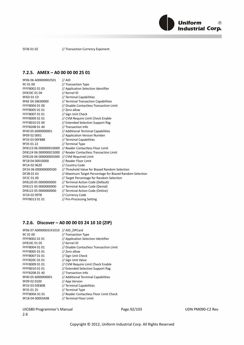
UIC680 Programmer’s Manual Page.92/103 UDN PM090‐C2 Rev. 2.6
Copyright © 2012, Uniform Industrial Corp. All Rights Reserved
5F36 01 02 // Transaction Currency Exponent
7.2.5. AMEX – A0 00 00 00 25 01 9F06 06 A00000002501 // AID 9C 01 00 // Transaction Type FFFF8002 01 03 // Application Selection Identifier DF810C 01 04 // Kernel ID 9F6D 01 C0 // Terminal Capabilities 9F6E 04 58E00000 // Terminal Transaction Capabilities FFFF8004 01 00 // Disable Contactless Transaction Limit FFFF8005 01 01 // Zero allow FFFF8007 01 01 // Sign Unit Check FFFF8009 01 01 // CVM Require Limit Check Enable FFFF8010 01 00 // Extended Selection Support flag FFFF8208 01 40 // Transaction Info 9F40 05 6000000001 // Additional Terminal Capabilities 9F09 02 0001 // Application Version Number 9F33 03 00F888 // Terminal Capabilities 9F35 01 22 // Terminal Type DF8123 06 000000010000 // Reader Contactless Floor Limit DF8124 06 000000015000 // Reader Contactless Transaction Limit DF8126 06 000000005000 // CVM Required Limit 9F1B 04 00010000 // Reader Floor Limit 9F1A 02 0620 // Country Code DF2A 06 000000000500 // Threshold Value for Biased Random Selection DF2B 01 63 // Maximum Target Percentage for Biased Random Selection DF2C 01 00 // Target Percentage for Random Selection DF8120 05 0000000000 // Terminal Action Code (Default) DF8121 05 0000000000 // Terminal Action Code (Denial) DF8122 05 0000000000 // Terminal Action Code (Online) 5F2A 02 0978 // Currency Code FFFF8013 01 01 // Pre‐Processing Setting
7.2.6. Discover – A0 00 00 03 24 10 10 (ZIP) 9F06 07 A0000003241010 // AID_ZIPCard 9C 01 00 // Transaction Type FFFF8002 01 01 // Application Selection Identifier DF810C 01 05 // Kernel ID FFFF8004 01 01 // Disable Contactless Transaction Limit FFFF8005 01 01 // Zero allow FFFF8007 01 01 // Sign Unit Check FFFF820C 01 01 // Sign Unit Value FFFF8009 01 01 // CVM Require Limit Check Enable FFFF8010 01 01 // Extended Selection Support flag FFFF8208 01 40 // Transaction Info 9F40 05 6000000001 // Additional Terminal Capabilities 9F09 02 0100 // App Version 9F33 03 E0E808 // Terminal Capabilities 9F35 01 25 // Terminal Type FFFF800A 01 01 // Reader Contactless Floor Limit Check 9F1B 04 00003A98 // Terminal Floor Limit
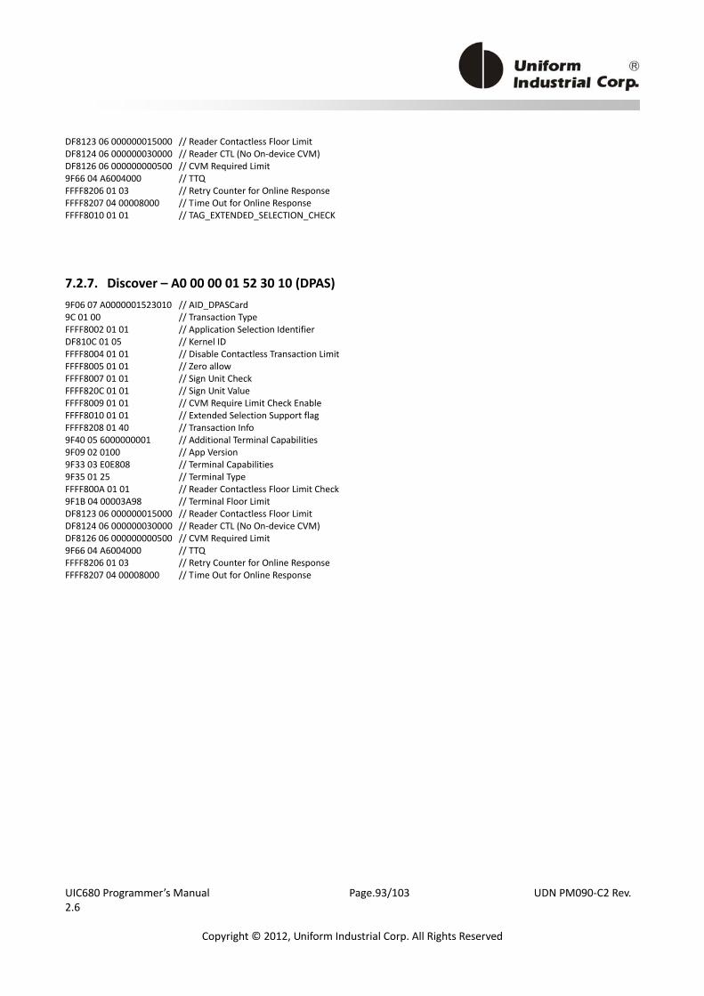
UIC680 Programmer’s Manual Page.93/103 UDN PM090‐C2 Rev. 2.6
Copyright © 2012, Uniform Industrial Corp. All Rights Reserved
DF8123 06 000000015000 // Reader Contactless Floor Limit DF8124 06 000000030000 // Reader CTL (No On‐device CVM) DF8126 06 000000000500 // CVM Required Limit 9F66 04 A6004000 // TTQ FFFF8206 01 03 // Retry Counter for Online Response FFFF8207 04 00008000 // Time Out for Online Response FFFF8010 01 01 // TAG_EXTENDED_SELECTION_CHECK
7.2.7. Discover – A0 00 00 01 52 30 10 (DPAS) 9F06 07 A0000001523010 // AID_DPASCard 9C 01 00 // Transaction Type FFFF8002 01 01 // Application Selection Identifier DF810C 01 05 // Kernel ID FFFF8004 01 01 // Disable Contactless Transaction Limit FFFF8005 01 01 // Zero allow FFFF8007 01 01 // Sign Unit Check FFFF820C 01 01 // Sign Unit Value FFFF8009 01 01 // CVM Require Limit Check Enable FFFF8010 01 01 // Extended Selection Support flag FFFF8208 01 40 // Transaction Info 9F40 05 6000000001 // Additional Terminal Capabilities 9F09 02 0100 // App Version 9F33 03 E0E808 // Terminal Capabilities 9F35 01 25 // Terminal Type FFFF800A 01 01 // Reader Contactless Floor Limit Check 9F1B 04 00003A98 // Terminal Floor Limit DF8123 06 000000015000 // Reader Contactless Floor Limit DF8124 06 000000030000 // Reader CTL (No On‐device CVM) DF8126 06 000000000500 // CVM Required Limit 9F66 04 A6004000 // TTQ FFFF8206 01 03 // Retry Counter for Online Response FFFF8207 04 00008000 // Time Out for Online Response
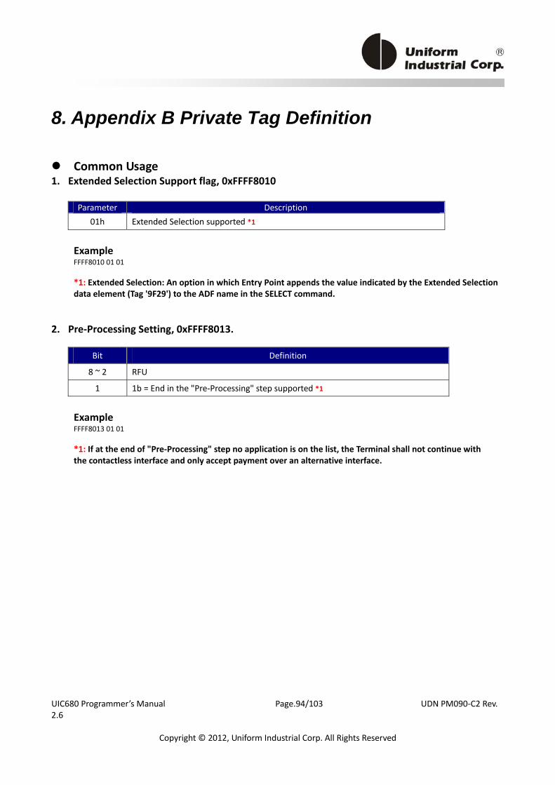
UIC680 Programmer’s Manual Page.94/103 UDN PM090‐C2 Rev. 2.6
Copyright © 2012, Uniform Industrial Corp. All Rights Reserved
8. Appendix B Private Tag Definition
Common Usage 1. Extended Selection Support flag, 0xFFFF8010
Parameter Description 01h Extended Selection supported *1
Example FFFF8010 01 01 *1: Extended Selection: An option in which Entry Point appends the value indicated by the Extended Selection data element (Tag '9F29') to the ADF name in the SELECT command.
2. Pre‐Processing Setting, 0xFFFF8013.
Bit Definition
8 ~ 2 RFU
1 1b = End in the "Pre‐Processing" step supported *1
Example FFFF8013 01 01 *1: If at the end of "Pre‐Processing" step no application is on the list, the Terminal shall not continue with the contactless interface and only accept payment over an alternative interface.
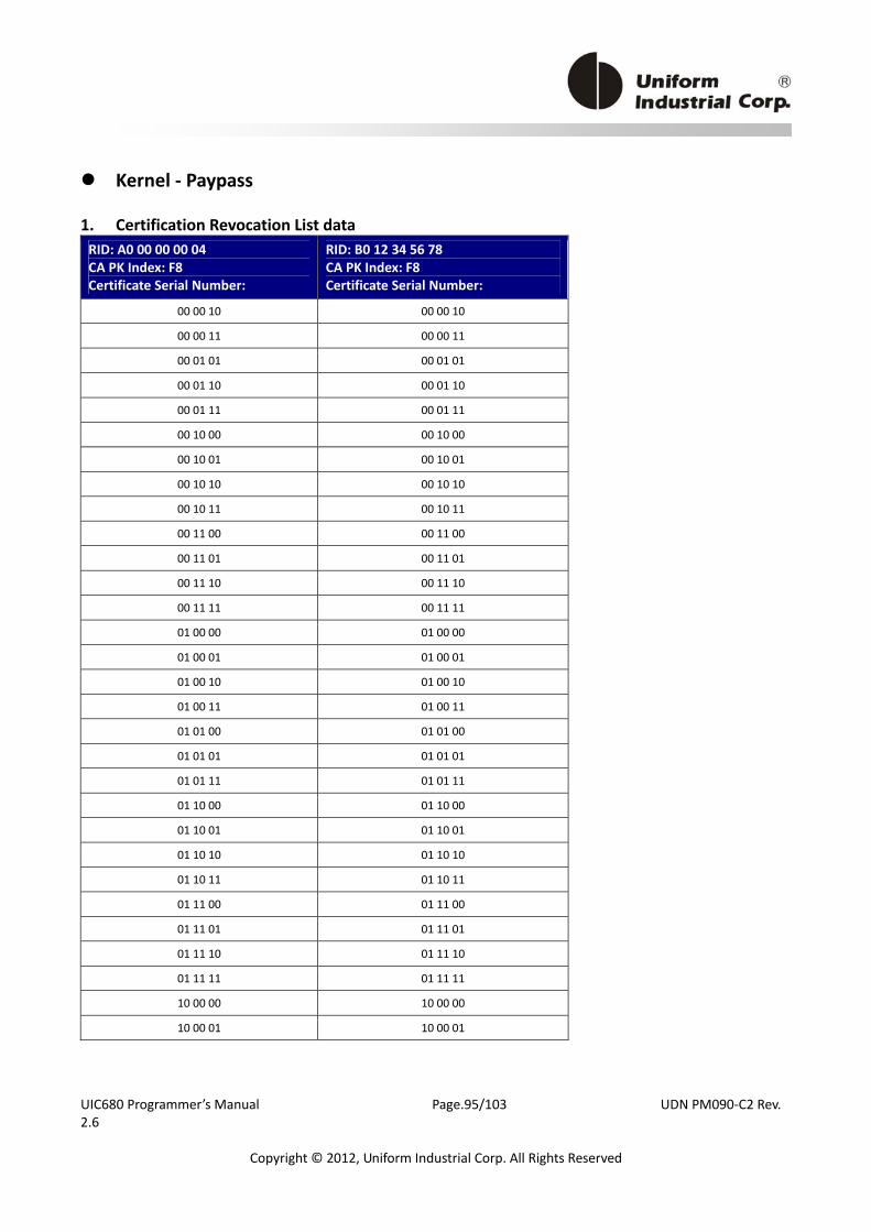
UIC680 Programmer’s Manual Page.95/103 UDN PM090‐C2 Rev. 2.6
Copyright © 2012, Uniform Industrial Corp. All Rights Reserved
Kernel ‐ Paypass 1. Certification Revocation List data RID: A0 00 00 00 04 CA PK Index: F8 Certificate Serial Number:
RID: B0 12 34 56 78 CA PK Index: F8 Certificate Serial Number:
00 00 10 00 00 10
00 00 11 00 00 11
00 01 01 00 01 01
00 01 10 00 01 10
00 01 11 00 01 11
00 10 00 00 10 00
00 10 01 00 10 01
00 10 10 00 10 10
00 10 11 00 10 11
00 11 00 00 11 00
00 11 01 00 11 01
00 11 10 00 11 10
00 11 11 00 11 11
01 00 00 01 00 00
01 00 01 01 00 01
01 00 10 01 00 10
01 00 11 01 00 11
01 01 00 01 01 00
01 01 01 01 01 01
01 01 11 01 01 11
01 10 00 01 10 00
01 10 01 01 10 01
01 10 10 01 10 10
01 10 11 01 10 11
01 11 00 01 11 00
01 11 01 01 11 01
01 11 10 01 11 10
01 11 11 01 11 11
10 00 00 10 00 00
10 00 01 10 00 01

UIC680 Programmer’s Manual Page.96/103 UDN PM090‐C2 Rev. 2.6
Copyright © 2012, Uniform Industrial Corp. All Rights Reserved
The format of Private Tag, Certification Revocation List (0xFFFF8211), is set as below, FFFF8211 81C4 A0000000045CF85A000010000011000101000110000111001000001001001010001011001100001101001110001111010000010001010010010011010100010101010111011000011001011010011011011100011101011110011111100000100001B0123456785CF85A000010000011000101000110000111001000001001001010001011001100001101001110001111010000010001010010010011010100010101010111011000011001011010011011011100011101011110011111100000100001 2. Default Setting in Phone Message Table ID PCII MASK PCII VALUE MESSAGE STATUS
1 00 08 00 00 08 00 20 (SEE PHONE)* 00 (NOT READY) *
2 00 04 00 00 04 00 20 (SEE PHONE) * 00 (NOT READY) *
3 00 01 00 00 01 00 20 (SEE PHONE) * 00 (NOT READY) *
4 00 02 00 00 02 00 20 (SEE PHONE) * 00 (NOT READY) *
5 00 00 00 00 00 00 07 (DECLINED) * 00 (NOT READY) *
Note: defined in the tag of User Interface Request Data, 0xDF8116
The format of Private Tag, Phone Message Table (0xFFFF8210), is set as below, FFFF8210 32 00080000080020000004000004002000000100000100200000020000020020000000000000000700
3. The Private Tags of Signal Out, 0xFFFF8212, and Message Out, 0xFFFF8213 In Paypass 3.0, it defined two special signals called OUT Signal and MSG Signal. The OUT Signal indicates the outcome of the transaction. It contains a subset of Outcome from the kernel. The MSG Signal is used as a carrier of the User Interface Request Data. In order to meet the performance requirement and more convenient for user to access, UIC defines two private tags for user to get and parse after transaction. Both of Tags are built as TLV format. But the Length in Data field is non‐TLV and fixed as 2 bytes. For each pair of Length + Data, it presents the transaction result in turn.
Tag Name Length Data Field
FFFF8212 Signal Out n bytes (TLV format) [Length (2bytes) + Data] * n
FFFF8213 Message Out n bytes (TLV format) [Length (2bytes) + Data] * n
Example Msg Out: Send: <CE>FFFF8213x Receive: 003DFFFF821338001ADF8116161E040000000000000000000000000000000000000000001ADF8116161B000000000000000000000000000000000000000000
The result can be parsed as below, ‐‐‐‐‐‐‐‐‐‐‐‐‐‐‐
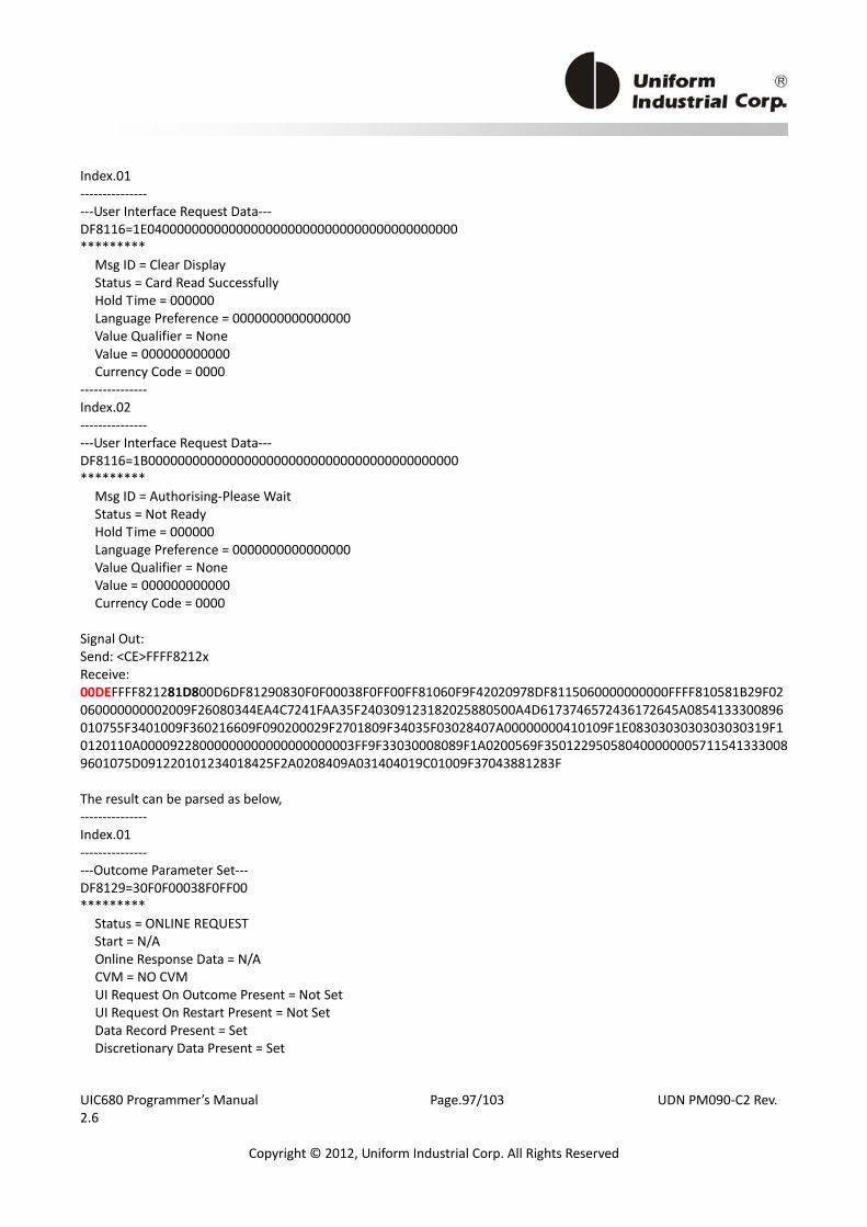
UIC680 Programmer’s Manual Page.97/103 UDN PM090‐C2 Rev. 2.6
Copyright © 2012, Uniform Industrial Corp. All Rights Reserved
Index.01 ‐‐‐‐‐‐‐‐‐‐‐‐‐‐‐ ‐‐‐User Interface Request Data‐‐‐ DF8116=1E040000000000000000000000000000000000000000 ********* Msg ID = Clear Display Status = Card Read Successfully Hold Time = 000000 Language Preference = 0000000000000000 Value Qualifier = None Value = 000000000000 Currency Code = 0000 ‐‐‐‐‐‐‐‐‐‐‐‐‐‐‐ Index.02 ‐‐‐‐‐‐‐‐‐‐‐‐‐‐‐ ‐‐‐User Interface Request Data‐‐‐ DF8116=1B000000000000000000000000000000000000000000 ********* Msg ID = Authorising‐Please Wait Status = Not Ready Hold Time = 000000 Language Preference = 0000000000000000 Value Qualifier = None Value = 000000000000 Currency Code = 0000 Signal Out: Send: <CE>FFFF8212x Receive: 00DEFFFF821281D800D6DF81290830F0F00038F0FF00FF81060F9F42020978DF8115060000000000FFFF810581B29F02060000000002009F26080344EA4C7241FAA35F240309123182025880500A4D6173746572436172645A0854133300896010755F3401009F360216609F090200029F2701809F34035F03028407A00000000410109F1E0830303030303030319F10120110A00009228000000000000000000003FF9F33030008089F1A0200569F3501229505804000000057115413330089601075D091220101234018425F2A0208409A031404019C01009F37043881283F The result can be parsed as below, ‐‐‐‐‐‐‐‐‐‐‐‐‐‐‐ Index.01 ‐‐‐‐‐‐‐‐‐‐‐‐‐‐‐ ‐‐‐Outcome Parameter Set‐‐‐ DF8129=30F0F00038F0FF00 ********* Status = ONLINE REQUEST Start = N/A Online Response Data = N/A CVM = NO CVM UI Request On Outcome Present = Not Set UI Request On Restart Present = Not Set Data Record Present = Set Discretionary Data Present = Set

UIC680 Programmer’s Manual Page.98/103 UDN PM090‐C2 Rev. 2.6
Copyright © 2012, Uniform Industrial Corp. All Rights Reserved
Receipt = Yes Alternate Interface Preference = N/A Field Off Request = N/A Remove Timeout = 00 ‐‐‐Discretionary Data‐‐‐ FF8106=9F42020978DF8115060000000000FF ********* 9F42 = 0978 ‐‐‐Error Indication‐‐‐ DF8115=0000000000FF ********* L1=OK L2=OK L3=OK SW12=0000 MsgOnErr=N/A ‐‐‐Data Record‐‐‐ FF8105=9F02060000000002009F26080344EA4C7241FAA35F240309123182025880500A4D6173746572436172645A0854133300896010755F3401009F360216609F090200029F2701809F34035F03028407A00000000410109F1E0830303030303030319F10120110A00009228000000000000000000003FF9F33030008089F1A0200569F3501229505804000000057115413330089601075D091220101234018425F2A0208409A031404019C01009F37043881283F ********* 9F02 = 000000000200 9F26 = 0344EA4C7241FAA3 5F24 = 091231 82 = 5880 50 = 4D617374657243617264 5A = 5413330089601075 5F34 = 00 9F36 = 1660 9F09 = 0002 9F27 = 80 9F34 = 5F0302 84 = A0000000041010 9F1E = 3030303030303031 9F10 = 0110A00009228000000000000000000003FF 9F33 = 000808 9F1A = 0056 9F35 = 22 95 = 8040000000 57 = 5413330089601075D09122010123401842 5F2A = 0840 9A = 140401 9C = 00 9F37 = 3881283F
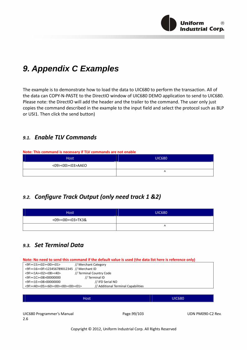
UIC680 Programmer’s Manual Page.99/103 UDN PM090‐C2 Rev. 2.6
Copyright © 2012, Uniform Industrial Corp. All Rights Reserved
9. Appendix C Examples
The example is to demonstrate how to load the data to UIC680 to perform the transaction. All of the data can COPY‐N‐PASTE to the DirectIO window of UIC680 DEMO application to send to UIC680. Please note: the DirectIO will add the header and the trailer to the command. The user only just copies the command described in the example to the input field and select the protocol such as BLP or USI1. Then click the send button)
9.1. Enable TLV Commands
Note: This command is necessary if TLV commands are not enable Host UIC680
<09><00><03>AAEO
^
9.2. Configure Track Output (only need track 1 &2)
Host UIC680
<09><00><03>TK3&
^
9.3. Set Terminal Data
Note: No need to send this command if the default value is used (the data list here is reference only) <9F><15><02><00><01> // Merchant Category <9F><16><0F>123456789012345 // Merchant ID <9F><1A><02><08><40> // Terminal Country Code <9F><1C><08>00000000 // Terminal ID <9F><1E><08>00000000 // IFD Serial NO <9F><40><05><60><00><00><00><01> // Additional Terminal Capabilities
Host UIC680
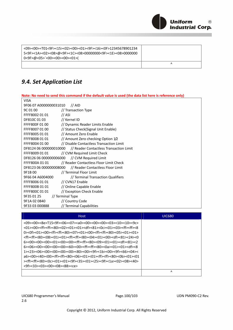
UIC680 Programmer’s Manual Page.100/103 UDN PM090‐C2 Rev. 2.6
Copyright © 2012, Uniform Industrial Corp. All Rights Reserved
<09><00>=T01<9F><15><02><00><01><9F><16><0F>123456789012345<9F><1A><02><08>@<9F><1C><08>00000000<9F><1E><08>00000000<9F>@<05>`<00><00><00><01>(
^
9.4. Set Application List
Note: No need to send this command if the default value is used (the data list here is reference only) VISA 9F06 07 A0000000031010 // AID 9C 01 00 // Transaction Type FFFF8002 01 01 // ASI DF810C 01 03 // Kernel ID FFFF800F 01 00 // Dynamic Reader Limits Enable FFFF8007 01 00 // Status Check(Signal Unit Enable) FFFF8005 01 01 // Amount Zero Enable FFFF8008 01 01 // Amount Zero checking Option 1/2 FFFF8004 01 00 // Disable Contactless Transaction Limit DF8124 06 000000010000 // Reader Contactless Transaction Limit FFFF8009 01 01 // CVM Required Limit Check DF8126 06 000000006000 // CVM Required Limit FFFF800A 01 01 // Reader Contactless Floor Limit Check DF8123 06 000000008000 // Reader Contactless Floor Limit 9F1B 00 // Terminal Floor Limit 9F66 04 A6004000 // Terminal Transaction Qualifiers FFFF8006 01 01 // CVN17 Enable FFFF800B 01 01 // Online Capable Enable FFFF800C 01 01 // Exception Check Enable 9F35 01 25 // Terminal Type 9F1A 02 0840 // Country Code 9F33 03 000888 // Terminal Capabilities
Host UIC680
<09><00><8e>T15<9f><06><07><a0><00><00><00><03><10><10><9c><01><00><ff><ff><80><02><01><01><df><81><0c><01><03><ff><ff><80><0f><01><00><ff><ff><80><07><01><00><ff><ff><80><05><01><01><ff><ff><80><08><01><01><ff><ff><80><04><01><00><df><81><24><06><00><00><00><01><00><00><ff><ff><80><09><01><01><df><81><26><06><00><00><00><00><60><00><ff><ff><80><0a><01><01><df><81><23><06><00><00><00><00><80><00><9f><1b><00><9f><66><04><a6><00><40><00><ff><ff><80><06><01><01><ff><ff><80><0b><01><01><ff><ff><80><0c><01><01><9f><35><01><25><9f><1a><02><08><40><9f><33><03><00><08><88><ce>
^
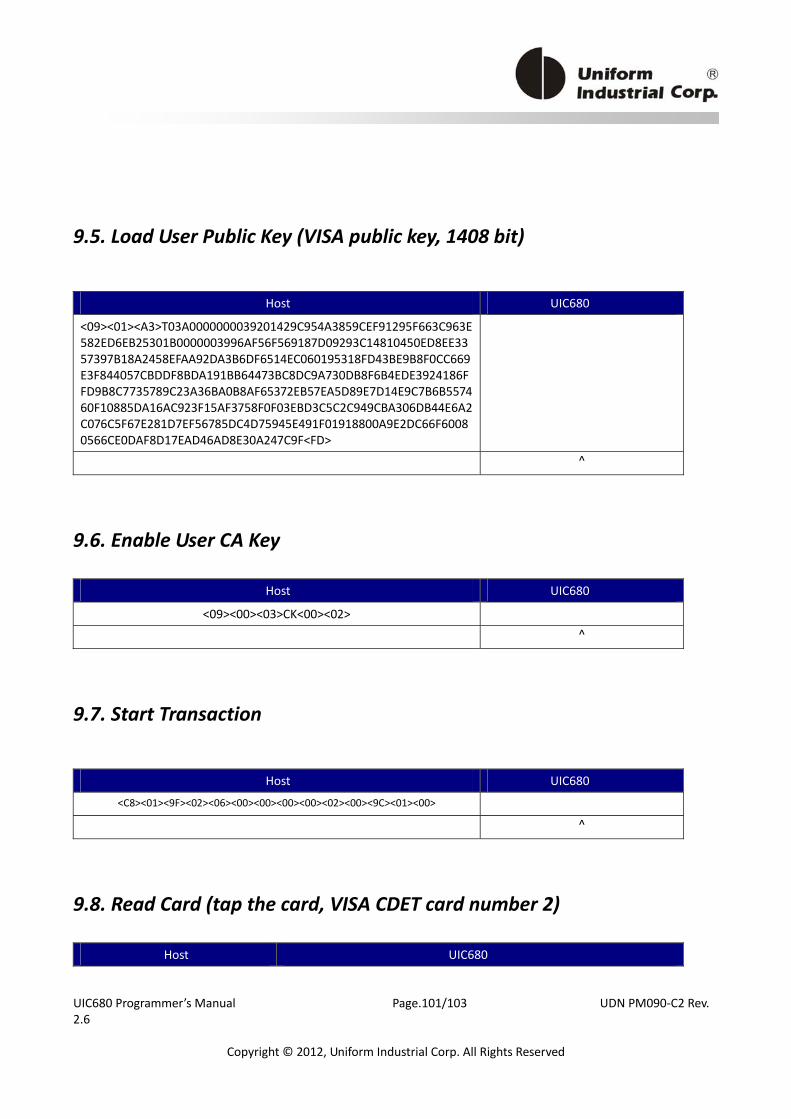
UIC680 Programmer’s Manual Page.101/103 UDN PM090‐C2 Rev. 2.6
Copyright © 2012, Uniform Industrial Corp. All Rights Reserved
9.5. Load User Public Key (VISA public key, 1408 bit)
Host UIC680
<09><01><A3>T03A0000000039201429C954A3859CEF91295F663C963E582ED6EB25301B0000003996AF56F569187D09293C14810450ED8EE3357397B18A2458EFAA92DA3B6DF6514EC060195318FD43BE9B8F0CC669E3F844057CBDDF8BDA191BB64473BC8DC9A730DB8F6B4EDE3924186FFD9B8C7735789C23A36BA0B8AF65372EB57EA5D89E7D14E9C7B6B557460F10885DA16AC923F15AF3758F0F03EBD3C5C2C949CBA306DB44E6A2C076C5F67E281D7EF56785DC4D75945E491F01918800A9E2DC66F60080566CE0DAF8D17EAD46AD8E30A247C9F<FD>
^
9.6. Enable User CA Key
Host UIC680
<09><00><03>CK<00><02>
^
9.7. Start Transaction
Host UIC680
<C8><01><9F><02><06><00><00><00><00><02><00><9C><01><00>
^
9.8. Read Card (tap the card, VISA CDET card number 2)
Host UIC680
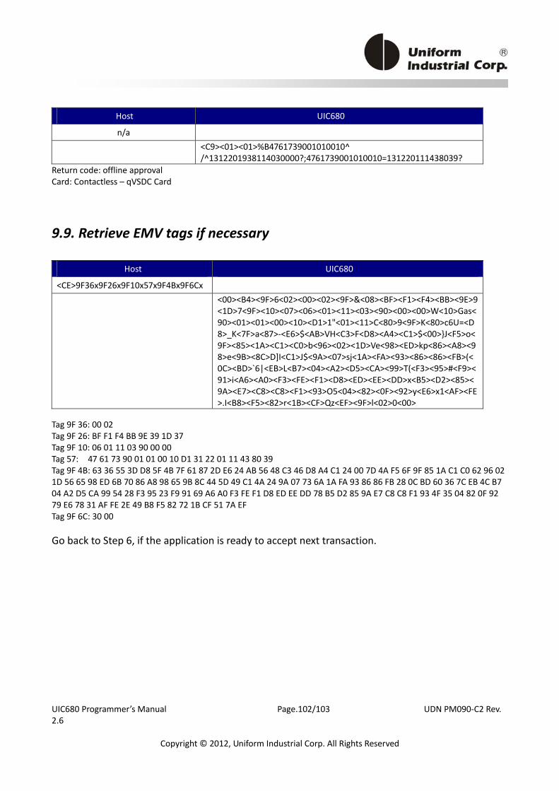
UIC680 Programmer’s Manual Page.102/103 UDN PM090‐C2 Rev. 2.6
Copyright © 2012, Uniform Industrial Corp. All Rights Reserved
Host UIC680
n/a
<C9><01><01>%B4761739001010010^ /^1312201938114030000?;4761739001010010=131220111438039?
Return code: offline approval Card: Contactless – qVSDC Card
9.9. Retrieve EMV tags if necessary
Host UIC680
<CE>9F36x9F26x9F10x57x9F4Bx9F6Cx
<00><B4><9F>6<02><00><02><9F>&<08><BF><F1><F4><BB><9E>9<1D>7<9F><10><07><06><01><11><03><90><00><00>W<10>Gas<90><01><01><00><10><D1>1"<01><11>C<80>9<9F>K<80>c6U=<D8>_K<7F>a<87>‐<E6>$<AB>VH<C3>F<D8><A4><C1>$<00>}J<F5>o<9F><85><1A><C1><C0>b<96><02><1D>Ve<98><ED>kp<86><A8><98>e<9B><8C>D]I<C1>J$<9A><07>sj<1A><FA><93><86><86><FB>(<0C><BD>`6|<EB>L<B7><04><A2><D5><CA><99>T(<F3><95>#<F9><91>i<A6><A0><F3><FE><F1><D8><ED><EE><DD>x<B5><D2><85><9A><E7><C8><C8><F1><93>O5<04><82><0F><92>y<E6>x1<AF><FE>.I<B8><F5><82>r<1B><CF>Qz<EF><9F>l<02>0<00>
Tag 9F 36: 00 02 Tag 9F 26: BF F1 F4 BB 9E 39 1D 37 Tag 9F 10: 06 01 11 03 90 00 00 Tag 57: 47 61 73 90 01 01 00 10 D1 31 22 01 11 43 80 39 Tag 9F 4B: 63 36 55 3D D8 5F 4B 7F 61 87 2D E6 24 AB 56 48 C3 46 D8 A4 C1 24 00 7D 4A F5 6F 9F 85 1A C1 C0 62 96 02 1D 56 65 98 ED 6B 70 86 A8 98 65 9B 8C 44 5D 49 C1 4A 24 9A 07 73 6A 1A FA 93 86 86 FB 28 0C BD 60 36 7C EB 4C B7 04 A2 D5 CA 99 54 28 F3 95 23 F9 91 69 A6 A0 F3 FE F1 D8 ED EE DD 78 B5 D2 85 9A E7 C8 C8 F1 93 4F 35 04 82 0F 92 79 E6 78 31 AF FE 2E 49 B8 F5 82 72 1B CF 51 7A EF Tag 9F 6C: 30 00 Go back to Step 6, if the application is ready to accept next transaction.