ug ppt
DESCRIPTION
ugTRANSCRIPT

EVOLUTION OF UNIGRAPHICS• 1960 - McDonnell Douglas Automation Company founded.• 1976 - United Computing, developer of the Unigraphics
CAD/CAM/CAE system, acquired.• 1983 - UG II introduced to market, General Motors selects
company as a Strategic Partner.• 1987 - Shape Data Ltd. acquired for solid modeling capabilities
- Parasolid - The production -proven kernel modeling toolkit.
• 1989 - McDonnell Douglas (now Boeing) chooses Unigraphics as the corporate standard for mechanicalCAD/CAM/CAE.
• 1990 - GE Aircraft Engine and GE Power Generation select Unigraphics as their CAD/CAM system. EDS acquires the Unigraphics Division, renames the company EDS Unigraphics.

• 1995 - EDS splits off from GM, becoming an independent
company. General Motors signs largest CAD/CAM contract in history selecting Unigraphics as its single vehicle development software platform.
-Parasolid rapidly gains widespread penetration into market as standard for high-end, mid-range and
commercial CAD/CAM/CAE development.
• 1996 - Bell Helicopter Textron Inc. enters into an initial agreement for CAD/CAM and data management seats for use on
the newly approved H-1 Helicopter
• 1998 - EDS Unigraphics becomes a subsidiary of EDS, takes the name Unigraphics Solutions EDS/Unigraphics Solutions Finalizes Acquisition of Intergraph's - Solid Edge and
EMS software

MASTER MODEL THEORY
ANALYSIS
ASSEMBLY MANUFACTURING
DRAFTINGMASTER MODEL

Unigraphics Screen

Modeling
Parametric Modeling
• Feature and Sketch based.
• Edit through expressions.
Non-parametric
• Curves and Freeform features

PRIMITIVES
– Simple analytic shapes.
• Block
• Cylinder
• Cone
• Sphere
• Tube

Form features
– Standard machined shapes in solids.
– Holes, slots, grooves, pockets, bosses and pads.
– Parametric

• Blends created varying from one edge to another.
• Radius defined at different points along the edge.
Variable Blend
BLEND
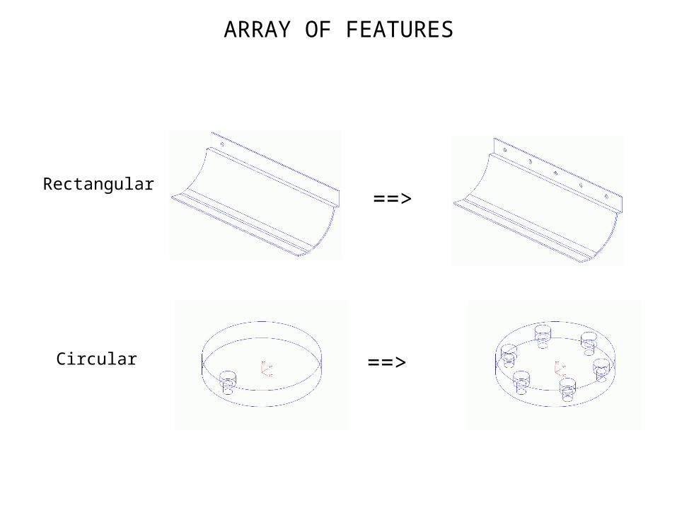
ARRAY OF FEATURES
Rectangular
Circular
==>
==>

SOLID MODELING
• Trim body– Split a body using a sheet or plane and choose which portions to keep.
– Useful in creating complicated surfaces on the model.
==>

MODEL NAVIGATION TOOL
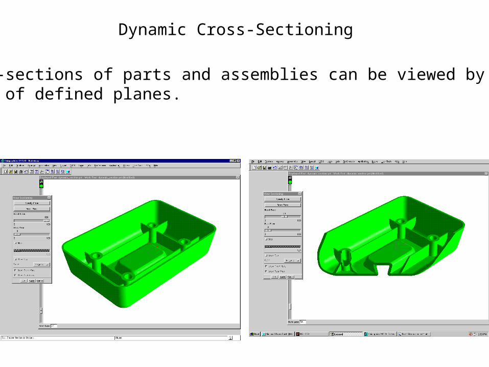
Dynamic Cross-Sectioning
Cross-sections of parts and assemblies can be viewed by moving a set of defined planes.

Curves
Toolbox ===> Curve

Curves
Curves extruded into a solid body
Curves created
Other features added to get the final model

Datum Planes & Datum Axes
• Reference features used for positioning of holes and otherfeatures
SKETCHER
• Tool to constrain a group of curves to meet the design intent
• Enable parametric modeling
• Can be created on flat solid faces or datum planes
• Can create new curves or add already existing curves
• Can be swept, revolved and extruded
• Fully associative to the solid created using it
ADVANTAGES
• Design intent evaluation for alternatives
• Easy modification
• Can create a family of parts from a sketch

FREE FORM FEATURES
• ConceptsConcepts
• Sheets - Solids of zero thickness
• Associated to the generating geometry
• Used for creating complicated shapes that cannot be modeled using standard solid features
• Complex shapes can be imparted to solid objects by using sheet solids to trim or split the solid
• Solid bodies can be generated by sewing sheets
• Parametrically driven

FREE FORM FEATURES
• Creation methods
– Through points
– From poles
– Through curves
– Through curve mesh
– Swept
– Conic surface
– Extension surface
– Fillet surface
– Offset surface
– Bounded planes
– Ruled surface
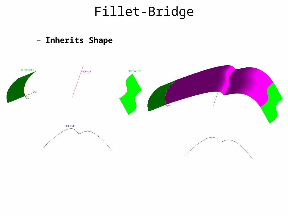
Fillet-Bridge
– Inherits Shape

• Face Blend
– Create trimmed or untrimmed spherical, conic and disc cross-
section blends that are tangent to two sets of faces..
FACE BLEND

Face Blend & Soft Blend
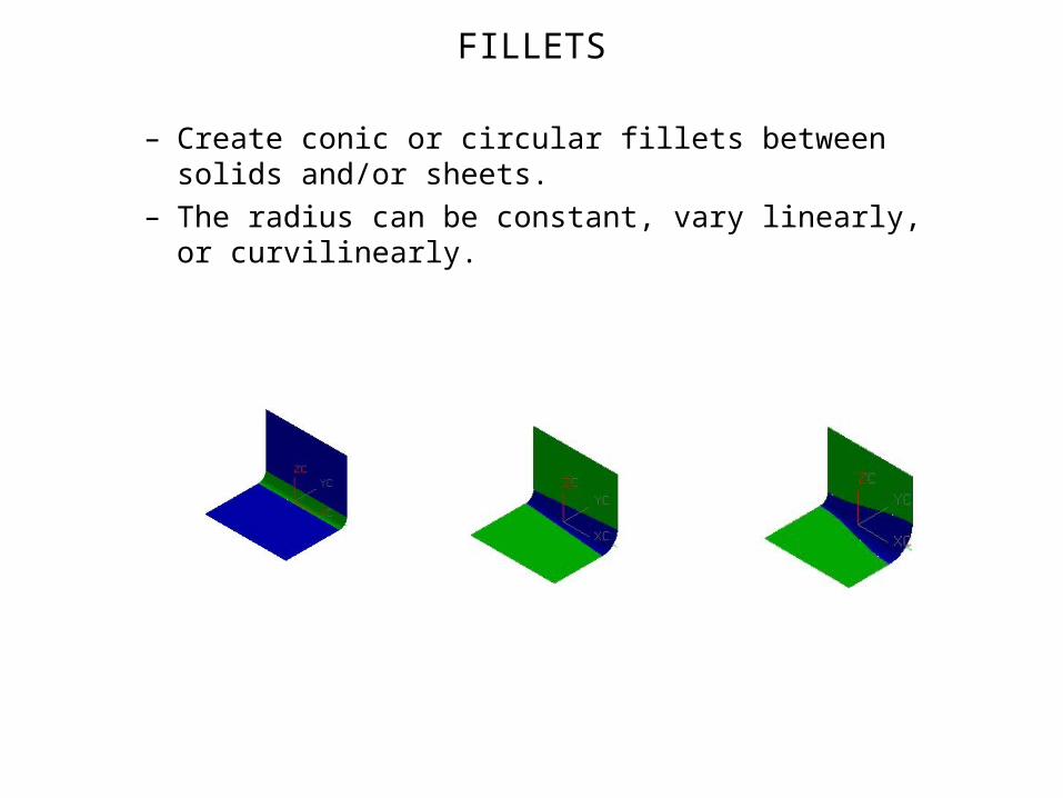
FILLETS
– Create conic or circular fillets between solids and/or sheets.
– The radius can be constant, vary linearly, or curvilinearly.
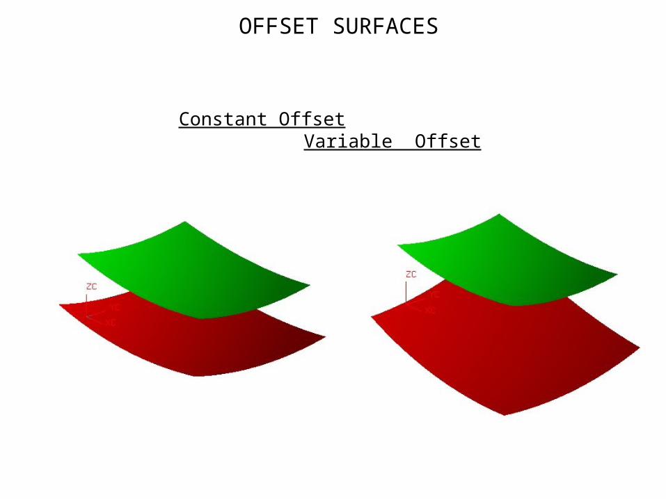
OFFSET SURFACES
Constant Offset Variable Offset
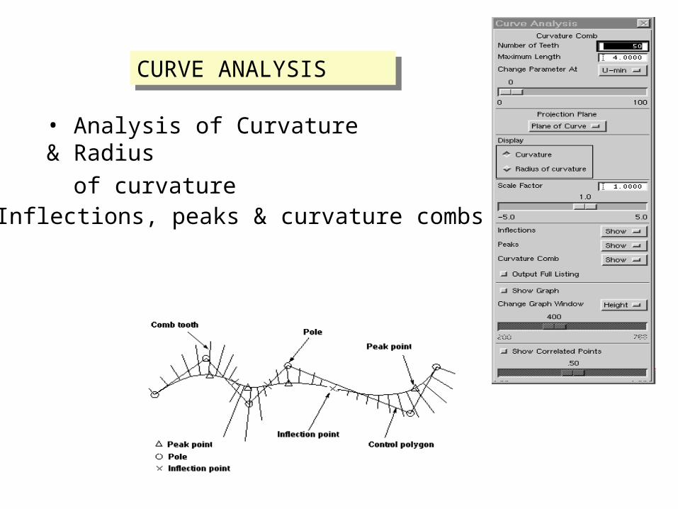
CURVE ANALYSISCURVE ANALYSIS
• Inflections, peaks & curvature combs
• Analysis of Curvature & Radius
of curvature

FACE ANALYSIS
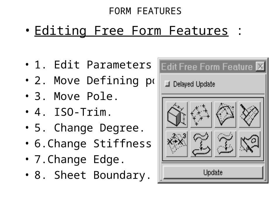
FORM FEATURES
• Editing Free Form Features :
• 1. Edit Parameters.• 2. Move Defining points.• 3. Move Pole.• 4. ISO-Trim. • 5. Change Degree.• 6.Change Stiffness.• 7.Change Edge.• 8. Sheet Boundary.

UNIQUE FEATURES OF UG CAM
• Fully integrated CAD/CAM • Ease of customization
and capturing manufacturing expertise
using a template• Supports both solids
& Surfaces• Creation of tools
& tool libraries• Multiple cut levels and
multiple feed rates

• Slow down at corners
& introduction of fillet radius
• Efficient scallop control
• Editing a tool path with
ease using graphical tool
path editor.• Multiple MCS in a single file• Tolerant machining.

POST PROCESSING & SIMULATION
• General purpose post processor- User can easily customize the post processor to the required controller.
• Simulation using vericut software.- Tool path simulation with gouge checks and excess material calculation.

CUSTOMIZATION
• Ease of creation of Operation templates

ASSEMBLIES
• TYPES OF ASSEMBLY CONSTRUCTION
• Multi_part approach
• Virtual Assembly approach
Assemblies is an integrated Unigraphics application that facilitates the construction of assemblies of parts, the modeling of individual parts within the context of the assembly, and the production of parts lists for assembly drawings

ASSEMBLY MODELING APPROACHES
• TOP-DOWN MODELING
• BOTTOM-UP MODELING
• MIXING AND MATCHING

TOP-DOWN MODELING:-
Creating an assembly at the top of the level hierarchy and move down the hierarchy, creating sub-assemblies and components
BOTTOM-UP MODELING:-
Starts by identifying the lowest level piece parts that will make up your assembly,and by creating
component parts and sub-assemblies as you move up the assembly level hierarchy
MIXING AND MATCHING:-
Mix these two approaches, when necessary, to add flexibility to your assembly design needs.
...

REFERENCE SETS
• Named partition of data in a part file
• Way to limit the amount of information from a component
Examples of data in Reference sets • Geometry• Co-ordinate system• Sketch Geometry• Datum planes/planes• Body• Tool/fixture geometry
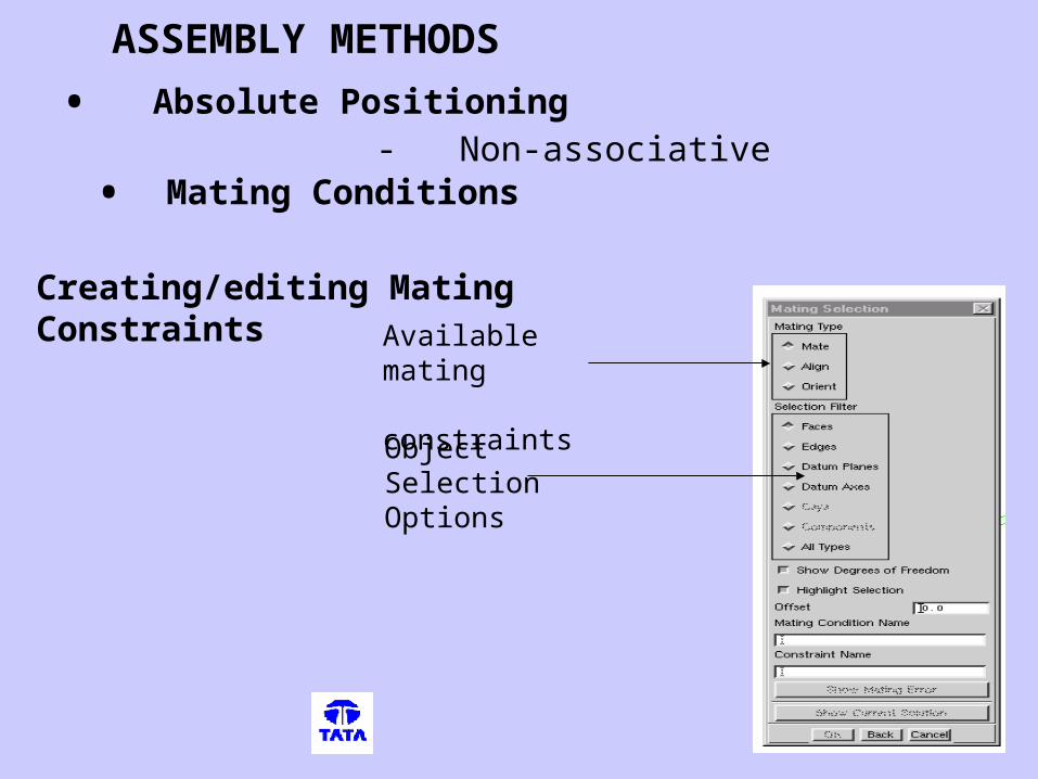
ASSEMBLY METHODS
Creating/editing Mating Constraints Available
mating constraints
ObjectSelectionOptions
• Absolute Positioning- Non-associative
• Mating Conditions

EXPLODED VIEWS
• Associative
• UG operations are allowed
COMPONENT ARRAYS
• To quickly create patterns of components and component mating conditions
ALTERNATES
• Substitutes a component retaining the mating conditions
SALIENT FEATURES OF ASSEMBLY MODELING

Advanced Assemblies
Faceted Representation
• Faceted reference set of the solid body • Are fully associative to their solid object counterparts.
• With large assemblies ,loading and model manipulation times are reduced
Clearance Analysis
• Checking the interference between components

Component Filtering
Can be filtered by
- Component sets - Assembly zones - Component filters and scripts.
Useful when
Designing-in-context,
Reviewing assembly designs
Documenting an assembly.
Weight Management
To calculate, display and manage the mass properties of component parts within large assemblies.
...

Inter part Expression
To establish relationships between expressions in separate part files.
Types of Interpart Expressions:-
PROMOTION OF BODY:
• Creates a solid from an existing solid body
• features can be added without changing basic
parameters
• Changes on the base body will be reflected in
the promoted body and not vice-versa.
UG/SCENARIO
• Application of analysis tools to predict the behavior of the
physical model in the digital domain
• Useful for the designer to evaluate the design alternatives
• Model idealization, simplification and optimization
• Associativity between the geometry and finite element data
• Automated meshing tools
• Good postprocessing capabilities

ADVANTAGES OF UG/SCENARIO
• Easy analysis of Unigraphics design model
UG/Scenario for FEA architecture makes conceptual
problem solving easier
Fewer steps used to perform analysis; therefore, time
is reduced
• If the geometry model is changed, the associated
finite element
data can be updated automatically, minimizing
rework

STEPS INVOLVED
• Preprocessing
- Boundary conditions
- Loads
- Materials
- Meshing
• Solve
• Postprocessing
- Animation
- Comparison of results
- Color coding
- Labels

Sheet Metal Design
Used for design of sheet metal components
Features supported:
.

The following feature standards are implemented in this module:
ŸFlange .
ŸInset Flange
ŸGeneralized Flange.
ŸSimple Sheet Metal Hole.
ŸSheet Metal Slot
ŸForm_Unform

Sheet Metal Fabrication
Sheet Metal Fabrication options assist in the manufacturing of sheet metal models.Ideal for full automation of manufacturing data.
Application Sheet Metal Fabrication.
Advantages: Automatic programming for standard shapes Graphical programming using operation icons, Addition of construction geometry during programming without modifying the master model, and NC source editing.

Sheet Metal Nesting
The Sheet Metal Nesting application furnishes automaticoptimized nesting of multiple NC programs controlled by theparameters that you specify.
Features of the Nesting application include: User selected nesting strategies, Automatic nesting of multiple parts, Nesting of parts within parts, Interactive nesting for special situations, and Optimized sheet repositioning and tool changing prior to postprocessing.

UG/SCENARIO
• Application of analysis tools to predict the behavior of the
physical model in the digital domain
• Useful for the designer to evaluate the design alternatives
• Model idealization, simplification and optimization
• Associativity between the geometry and finite element data
• Automated meshing tools
• Good postprocessing capabilities

ADVANTAGES OF UG/SCENARIO
• Easy analysis of Unigraphics design model
UG/Scenario for FEA architecture makes conceptual
problem solving easier
Fewer steps used to perform analysis; therefore, time
is reduced
• If the geometry model is changed, the associated
finite element
data can be updated automatically, minimizing
rework

STEPS INVOLVED
• Preprocessing
- Boundary conditions
- Loads
- Materials
- Meshing
• Solve
• Postprocessing
- Animation
- Comparison of results
- Color coding
- Labels

UG/OPEN
• UG/Open is a set of API’s (Application
Programming Interfaces that allows you to
- Customize the behavior of UG.
- Write tools that will enhance your productivity- ---
- Create Packages on top of UG that will capture your
design and manufacturing practices.
• Further, by using UG/Open along with the UI-Styler and
Menu script, you can change the User-interface of your
application as per your requirements.

COMPUTER-ASSISTED SELF TEACHINGHome Page
It’s an online- tutorial that guides the user in a
- Covers all modules extensively
- Step-by-step method of using each toolbar
- Projects at the end of each chapter
- Netscape browser for easy access

Translators Provides robust exchange of model and drawing information
• IGES,
• DXF to Unigraphics,Unigraphics to DXF
• UG/STEP AP203, UG/STEP AP214
• 2D Exchange
• Theorem (Bi-Directional CATIA to UG)
UG/Routing - Accelerates the creation of routing assemblies of applications
such as tubing and piping.
UG/Harness - This modules automates the process of designing and
manufacturing wire harnesses within assemblies