ug dial governor - varhaugs-maritime · table 4-1. test stand tools ... manual 03040 ug dial...
TRANSCRIPT
Installation and Operation Manual
UG Dial Governor
UG-5.7/UG-8/UG-10 Dial
Manual 03040 (Revision D)

WARNINGS FOLLOW INSTRUCTIONS—Read this entire manual and all other publications pertaining to the work to be performed before installing, operating, or servicing this equipment. Practice all plant and safety instructions and precautions. Failure to follow instructions can cause personal injury and/or property damage. OUT-OF-DATE PUBLICATION—This publication may have been revised or updated since this copy was produced. To verify that you have the latest revision, be sure to check the Woodward website:
www.woodward.com/pubs/current.pdf The revision level is shown at the bottom of the front cover after the publication number. The latest version of most publications is available at:
www.woodward.com/publications If your publication is not there, please contact your customer service representative to get the latest copy. OVERSPEED PROTECTION—The engine, turbine, or other type of prime mover should be equipped with an overspeed shutdown device to protect against runaway or damage to the prime mover with possible personal injury, loss of life, or property damage.
The overspeed shutdown device must be totally independent of the prime mover control system. An overtemperature or overpressure shutdown device may also be needed for safety, as appropriate.
CAUTIONS BATTERY CHARGING—To prevent damage to a control system that uses an alternator or battery-charging device, make sure the charging device is turned off before disconnecting the battery from the system. ELECTROSTATIC DISCHARGE—Electronic controls contain static-sensitive parts. Observe the following precautions to prevent damage to these parts. • Discharge body static before handling the control (with power to the control
turned off, contact a grounded surface and maintain contact while handling the control).
• Avoid all plastic, vinyl, and Styrofoam (except antistatic versions) around printed circuit boards.
• Do not touch the components or conductors on a printed circuit board with your hands or with conductive devices.
IMPORTANT DEFINITIONS WARNING—indicates a potentially hazardous situation which, if not avoided, could result in death or serious injury. CAUTION—indicates a potentially hazardous situation which, if not avoided, could result in damage to equipment. NOTE—provides other helpful information that does not fall under the warning or caution categories.
Woodward Governor Company reserves the right to update any portion of this publication at any time. Information provided by Woodward Governor Company is believed to be correct and reliable. However, no responsibility is assumed by Woodward Governor Company unless otherwise expressly undertaken.
© Woodward 1982 All Rights Reserved

Manual 03040 UG Dial Governor
Woodward i
Contents
CHAPTER 1. GENERAL INFORMATION........................................................... 1 Introduction.............................................................................................................1 Description..............................................................................................................1 References .............................................................................................................2 CHAPTER 2. INSTALLATION PROCEDURES.................................................... 4 Introduction.............................................................................................................4 Receiving................................................................................................................4 Storage ...................................................................................................................4 Mounting Requirements .........................................................................................4 Linkage Attachments..............................................................................................5 Oil Supply ...............................................................................................................7 CHAPTER 3. PRINCIPLES OF OPERATION ................................................... 10 Introduction...........................................................................................................10 Component Description........................................................................................10 Operation of the UG Dial Governor ......................................................................15 CHAPTER 4. GOVERNOR OPERATION AND ADJUSTMENTS .......................... 18 Introduction...........................................................................................................18 Initial Operation for a New Governor....................................................................18 Adjustments..........................................................................................................18 Compensation Adjustments .................................................................................18 Initial Operation for a Repaired or Reassembled Governor.................................20 Test Procedures ...................................................................................................22 Test Completion ...................................................................................................25 CHAPTER 5. TROUBLESHOOTING............................................................... 26 Introduction...........................................................................................................26 Troubleshooting....................................................................................................26 Definitions.............................................................................................................27 Preliminary Inspection ..........................................................................................27 Additional Information for Steam Turbines, Gas and Gasoline Engines..............31 Governor Field Repairs ........................................................................................32 Removal of Governor from Engine.......................................................................32 CHAPTER 6. REPLACEMENT PARTS ........................................................... 35 Replacement Parts Information............................................................................35 CHAPTER 7. AUXILIARY EQUIPMENT .......................................................... 46 Introduction...........................................................................................................46 Synchronizer Motor and Solenoid Shutdown.......................................................46 PM Synchronizer Motor with Housing ..................................................................48 Low Lube Oil Pressure Shutdown........................................................................49 Magnetic Speed Pickup........................................................................................49 Micro Switches and Wiring Harness ....................................................................50 CHAPTER 8. SERVICE OPTIONS ................................................................. 51 Product Service Options.......................................................................................51 Returning Equipment for Repair...........................................................................52 Replacement Parts ...............................................................................................53 How to Contact Woodward...................................................................................53 Engineering Services ...........................................................................................54 Technical Assistance............................................................................................55
UG Dial Governor Manual 03040
ii Woodward
Illustrations and Tables Figure 1-1. UG-8 Dial Governor ............................................................................ iv Figure 1-2. Recommended Output Shaft Travel Adjustment .................................2 Figure 1-3. UG Dial Governor Outline Drawing......................................................3 Figure 2-1. Linkage Arrangement (for non-linear fuel systems).............................6 Figure 3-1. UG Dial Governor Schematic Diagram..............................................12 Figure 4-1. Maximum/Minimum Speed Stop Adjustment on the Governor..........23 Figure 5-1. Common Bench Tools .......................................................................33 Figure 5-2. Normal Field Repair Tools .................................................................34 Figure 6-1a. Parts Illustration for the UG Dial Governor ......................................37 Figure 6-1b. Parts Illustration for the UG Dial Governor ......................................39 Figure 6-1c. Parts Illustration for the UG Dial Governor ......................................41 Figure 6-1d. Parts Illustration for the UG Dial Governor ......................................43 Figure 6-1e. Parts Illustration for the UG Dial Governor ......................................45 Figure 7-1. UG Cover with Bodine Motor and Shutdown Solenoid......................46 Figure 7-2. Installing Cover with Bodine Synchronizer Motor ..............................47 Figure 7-3. UG-8 Dial Governor Equipped with Bodine Synchronizer Motor.......47 Figure 7-4. Top View of Weatherproof Housing with PM Synchronizer Motor and
Shutdown Solenoid..........................................................................48 Figure 7-5. UG-8 Governor with PM Motor, Shutdown Weatherproof Housing...48 Figure 7-6. Low Lube Oil Pressure Shutdown .....................................................49 Figure 7-7. Magnetic Speed Pickup .....................................................................49 Figure 7-8. Micro Switches and Wiring.................................................................50 Figure 7-9. Wiring Harness on Cover...................................................................50 Table 2-1. Oil Chart ................................................................................................8 Table 2-2. Viscosity Comparisons..........................................................................8 Table 4-1. Test Stand Tools .................................................................................21 Table 5-1. Troubleshooting Chart.........................................................................28 Table 5-2. Governor Output Shaft Travel vs Butterfly Valve Travel .....................32 Table 5-3. List of Common Bench Tools ..............................................................33 Table 5-4. List of Normal Field Repair Tools........................................................34

Manual 03040 UG Dial Governor
Woodward iii
UG Dial Governor Manual 03040
iv Woodward
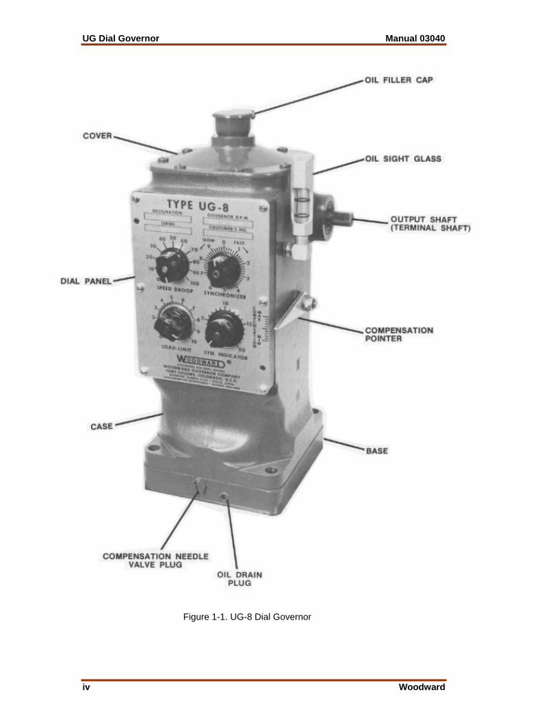
Figure 1-1. UG-8 Dial Governor

Manual 03040 UG Dial Governor
Woodward 1
Chapter 1. General Information
Introduction The UG Dial governor is available in three different work outputs: • UG-5.7—7.1 N m (5.2 lb-ft) • UG-8—13.2 N m (9.7 lb-ft) • UG-10—15.9 N m (11.7 lb-ft) The UG-5.7 and UG-8 both use 827 kPa (120 psi) oil pressure, and the UG-10 uses 1034 kPa (150 psi). Basic operation, adjustment, troubleshooting, and replacement of parts are similar for the UG-5.7, UG-8, and UG-10.
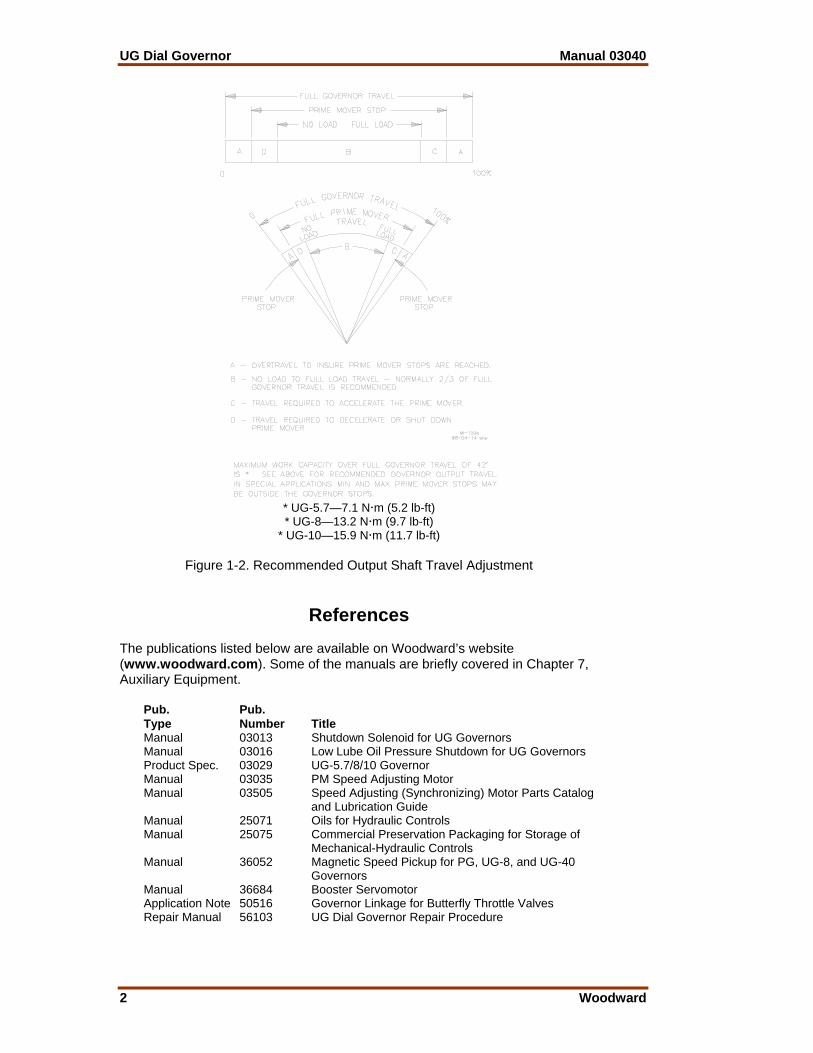
Description The UG is a mechanical-hydraulic governor for controlling diesel, gas, or dual fuel engines, or steam turbines. The UG is mechanically linked to the fuel racks or to the fuel valves, depending on the system. The maximum travel of the output (terminal) shaft is 42°.The recommended travel of the output shaft is 28° from no load to full load, which allows sufficient overtravel at each end so that the governor can shut down the prime mover and also give maximum fuel when required. See Figure 1-2 for recommended output shaft travel adjustment. Normally, the UG operates isochronously (constant speed) regardless of load on the engine, except as described in Chapter 3, Principles of Operation. Speed droop is incorporated in the UG Dial governor to divide and balance load between units driving the same shaft or paralleled in an electrical system. A load limit control is also a standard feature on the UG Dial governor. It limits the amount of fuel supplied by restricting the travel of the governor output shaft. An indicator dial shows the governor output shaft limit position. The load limit control may also be used for shutting down the prime mover by turning it to zero.
UG Dial Governor Manual 03040
2 Woodward
* UG-5.7—7.1 N m (5.2 lb-ft) * UG-8—13.2 N m (9.7 lb-ft)
* UG-10—15.9 N m (11.7 lb-ft)
Figure 1-2. Recommended Output Shaft Travel Adjustment
References The publications listed below are available on Woodward’s website (www.woodward.com). Some of the manuals are briefly covered in Chapter 7, Auxiliary Equipment. Pub. Pub. Type Number Title Manual 03013 Shutdown Solenoid for UG Governors Manual 03016 Low Lube Oil Pressure Shutdown for UG Governors Product Spec. 03029 UG-5.7/8/10 Governor Manual 03035 PM Speed Adjusting Motor Manual 03505 Speed Adjusting (Synchronizing) Motor Parts Catalog and Lubrication Guide Manual 25071 Oils for Hydraulic Controls Manual 25075 Commercial Preservation Packaging for Storage of Mechanical-Hydraulic Controls Manual 36052 Magnetic Speed Pickup for PG, UG-8, and UG-40 Governors Manual 36684 Booster Servomotor Application Note 50516 Governor Linkage for Butterfly Throttle Valves Repair Manual 56103 UG Dial Governor Repair Procedure

Manual 03040 UG Dial Governor
Woodward 3
Figure 1-3. UG Dial Governor Outline Drawing

UG Dial Governor Manual 03040
4 Woodward
Chapter 2. Installation Procedures
Introduction This chapter provides information necessary for receiving, storage, mounting, and start-up adjustments.
Receiving When you receive your UG governor, it will be bolted to a wooden platform in a vertical position. After testing the governor at the factory, it is drained of oil. This leaves a light film of oil covering the internal parts, preventing rust. No internal cleaning is required before installation. Some drive shafts are sprayed with a light film of oil while others (depending on customer requirements) are covered with soft seal. Before installation, remove the soft seal with a rag saturated with mineral spirits.
Storage If a governor is being stored for any period of time, please refer to Woodward manual 25075, Commercial Preservation Packaging for Storage of Mechanical-Hydraulic Controls.
Mounting Requirements 1. Make sure the drive shaft rotates freely. 2. Select the correct length of coupling between the governor and the prime
mover drive. 3. Mount the governor squarely on its mounting pad. 4. Make sure there is no force pushing the drive shaft into the governor. 5. See the outline drawing (Figure 1-3) for mounting hole sizes and governor
dimensions. 6. Make sure the coupling rotates freely but without backlash. Incorrect
alignment of the governor shaft to the coupling, or not enough clearance between any of the parts, can result in excessive wear and/or seizure of parts. It can also cause an undesirable high frequency vibration or “jiggle” in the governor output shaft (see Definitions in Chapter 5 for more information).
Manual 03040 UG Dial Governor
Woodward 5
The standard UG governor drive gives few installation problems if the alignment of the governor shaft to the drive coupling is kept.
WARNING—OVERSPEED In the event of a misaligned or broken drive shaft, an overspeed condition or runaway engine can develop. An overspeeding or runaway engine can result in extensive damage to the equipment, personal injury and/or loss of life. If an optional keyed drive is used when installing the governor, take care to avoid the following undesirable conditions: a. Rough gear teeth: Rough gear teeth, or shaft out of round, can cause vibrations which
can be transmitted to the governor and cause a jiggle in the governor output shaft. The jiggle can be transmitted to the fuel control resulting in an undesirable condition. Replace gears if necessary.
b. Incorrect shimming: Check backlash and re-adjust if necessary to obtain proper mesh
without binding or excessive backlash. Refer to the prime mover manufacturer’s specifications for the correct amount of backlash.
7. Mount the governor flush with the engine drive pad. If the engine drive pad
is at an angle (from 0° to 45° maximum), the UG must be installed with the front panel in the upper position. Use a gasket between the governor and the engine drive pad.
Be sure there is adequate space available around the governor to provide
easy access for installing the control linkage, filling the governor with oil, and adjusting the speed and compensation system. See the outline drawing (Figure 1-3) for mounting hole sizes and governor dimensions.
The recommended rated speed range for the governor drive is 1000 to 1500 rpm. The drive power requirement is 249 W (1/3 hp) at normal speed and operating temperature. The UG governor may be driven either clockwise or counterclockwise. Operating temperature range for the UG governor is –29 to +99 °C (–20 to +210 °F).
Linkage Attachments Adjustment of the fuel linkage must provide for control of fuel from “OFF” to “FULL FUEL” within the limits of the 42° of governor output shaft travel. It must also provide for approximately 30° output shaft travel between “NO LOAD” and “FULL LOAD”. Attach the fuel rack linkage to the governor output shaft. There must be no lost motion or binding in this linkage. Adequate locking methods must be employed on the linkage connections.
WARNING—OVERTRAVEL Be sure to allow sufficient overtravel at each end of the terminal shaft. Failure to provide sufficient overtravel at maximum fuel position can prevent the prime mover from giving maximum fuel when required. Failure to provide sufficient overtravel at minimum fuel position can prevent the governor from shutting down the prime mover and result in possible damage to equipment and personal injury.
UG Dial Governor Manual 03040
6 Woodward
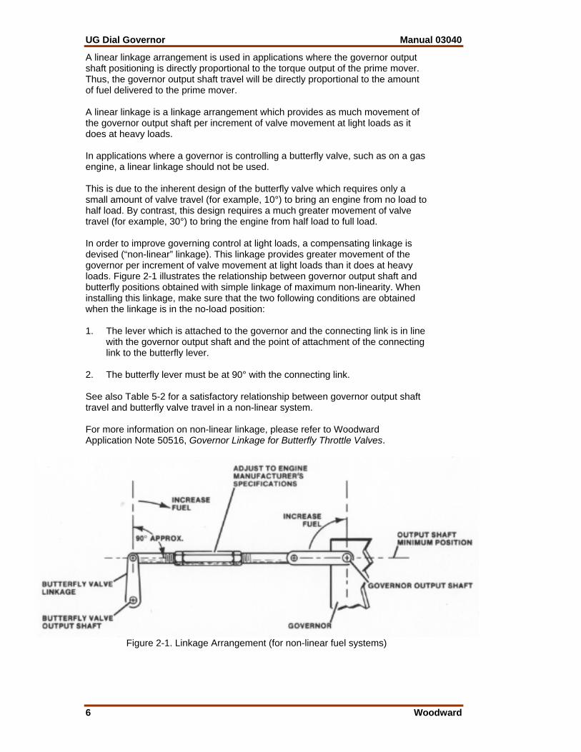
A linear linkage arrangement is used in applications where the governor output shaft positioning is directly proportional to the torque output of the prime mover. Thus, the governor output shaft travel will be directly proportional to the amount of fuel delivered to the prime mover. A linear linkage is a linkage arrangement which provides as much movement of the governor output shaft per increment of valve movement at light loads as it does at heavy loads. In applications where a governor is controlling a butterfly valve, such as on a gas engine, a linear linkage should not be used. This is due to the inherent design of the butterfly valve which requires only a small amount of valve travel (for example, 10°) to bring an engine from no load to half load. By contrast, this design requires a much greater movement of valve travel (for example, 30°) to bring the engine from half load to full load. In order to improve governing control at light loads, a compensating linkage is devised (“non-linear” linkage). This linkage provides greater movement of the governor per increment of valve movement at light loads than it does at heavy loads. Figure 2-1 illustrates the relationship between governor output shaft and butterfly positions obtained with simple linkage of maximum non-linearity. When installing this linkage, make sure that the two following conditions are obtained when the linkage is in the no-load position: 1. The lever which is attached to the governor and the connecting link is in line
with the governor output shaft and the point of attachment of the connecting link to the butterfly lever.
2. The butterfly lever must be at 90° with the connecting link. See also Table 5-2 for a satisfactory relationship between governor output shaft travel and butterfly valve travel in a non-linear system. For more information on non-linear linkage, please refer to Woodward Application Note 50516, Governor Linkage for Butterfly Throttle Valves.
Figure 2-1. Linkage Arrangement (for non-linear fuel systems)
Manual 03040 UG Dial Governor
Woodward 7
Oil Supply Use an oil depending on operating temperature for the governor (see Table 2-1).
NOTE Primary concern is for the oil properties in the governor. Fill the governor with approximately two quarts of oil to the mark on the oil sight glass. After the engine is started and the governor is at operating temperature, add oil if necessary. Oil must be visible in the glass under all operating conditions. Use the information given in Tables 2-1 and 2-2 as a guide in the selection of a suitable lubricating/hydraulic oil. Oil grade selection is based on the operating temperature range of the governor. Also, use this information to aid in recognizing and correcting common problems associated with oils used in governors. For applications where the governor shares the oil supply with the engine, use the oil recommended by the engine manufacturer. Governor oil is both a lubricating oil and a hydraulic oil. It must have a viscosity index that allows it to perform over the operating temperature range, and it must have the proper blending of additives that cause it to remain stable and predictable throughout this range. Governor oil must be compatible with seal materials (particularly nitrile, polyacrylic, and fluorocarbon). Many automotive and gas engine oils, industrial lubricating oils, and other oils of mineral or synthetic origin meet these requirements. Woodward governors are designed to give stable operation with most oils with the viscosity, at the operating temperature, between 50 and 3000 SUS (Saybolt Universal Seconds). At the normal operating temperature, the viscosity should be between 100 to 300 SUS. Poor actuator response or instability may be an indication that the oil viscosity is outside this range. Excessive component wear or seizure in a governor indicates the possibility of: 1. Insufficient lubrication caused by: a. An oil that flows slowly when it is cold, especially during start-up. b. No oil in the governor. 2. Contaminated oil caused by: a. Dirty oil containers. b. A governor exposed to heating up and cooling down cycles, which
creates condensation of water in the oil. 3. Oil not suitable for the operating conditions caused by: a. Changes in ambient temperature. b. An improper oil level which creates foamy, aerated oil.

UG Dial Governor Manual 03040
8 Woodward
Table 2-1. Oil Chart
Table 2-2. Viscosity Comparisons
Manual 03040 UG Dial Governor
Woodward 9
Operating a governor continuously beyond the high limit temperature of the oil will result in oil oxidation. This is identified by varnish or sludge deposits on the governor parts. To reduce oil oxidation, lower the actuator operating temperature with a heat exchanger or other means, or change to an oil more oxidation-resistant at the operating temperature.
WARNING—OIL VISCOSITY A loss of stable governor control and possible prime mover overspeed may result if the viscosity exceeds the 50 to 3000 SUS range. An overspeeding and/or runaway prime mover can result in extensive damage to the equipment, personal injury and/or loss of life. Specific oil viscosity recommendations are given on the oil chart (Table 2-1). Select a readily available good brand of oil, either mineral or synthetic, and continue using that same brand. Do NOT mix the different classes of oils. Oil that meets the API (American Petroleum Institute) engine service classification in either the “S” group or the “C” group, starting with “SA” or “CA” through “SF” and “CD” is suitable for governor service. Oils meeting performance requirements of the following specifications are also suitable: MIL-L-2104A, MIL-L-2104B, MIL-L-2104C, MIL-L-46152, MIL-L-46152A, MIL-L-46152B, MIL-L-45199B. Replace the governor oil if it is contaminated, also change it if it is suspected of contributing to the governor instability. Drain the oil while it is still hot and agitated; flush the governor with a clean solvent having some lubricating quality (such as fuel oil or kerosene) before refilling with new oil. If drain time is insufficient for the solvent to completely drain or evaporate, flush the governor with the same oil it is being refilled with to avoid dilution and possible contamination of the new oil. To avoid recontamination, the replacement oil should be free of dirt, water, and other foreign material. Use clean containers to store and transfer oil.
WARNING—SOLVENTS Observe the manufacturer’s instructions or restrictions regarding the use of solvents. If no instructions are available, handle with care. Use the cleaning solvent In a well ventilated area away from fires or sparks. Failure to follow the safety instructions above can result in dangerous fires, extensive damage to equipment, personal injury and/or loss of life. Oil that has been carefully selected to match the operating conditions and is compatible with governor components should give long service between oil changes. For governors operating under ideal conditions (minimum exposure to dust and water and within the temperature limits of the oil), oil changes can be extended. If available, a regularly scheduled oil analysis is helpful in determining the frequency of oil changes. Any persistent or recurring oil problems should be referred to a qualified oil specialist for solution. The recommended continuous operating temperature of the oil is 60 to 93 °C (140 to 200 °F). The ambient temperature limits are –29 to +93 °C (–20 to +200 °F). Measure the temperature of the governor on the outside lower part of the case. The actual oil temperature will be slightly warmer, approximately 6 °C (10 °F).

UG Dial Governor Manual 03040
10 Woodward
Chapter 3. Principles of Operation
Introduction Basic UG operation is similar for all types. The only difference is in the method of setting the speed. Auxiliary devices provide different functions but do not alter the basic operation of the governor. Along with the text, a schematic diagram (Figure 3-1) is provided for visual means of understanding the operation of the UG Dial governor. This schematic shows a basic design and does not include any auxiliary equipment.
Component Description Before getting into the operation of the UG, a brief description of the components will facilitate understanding the operation. Oil Pump The purpose of the oil pump (14) is to provide oil pressure for the governor. The pump gets its oil from the self-contained sump (15). The oil pump is a positive displacement gear pump with four check valves (13) for either direction of rotation. One pump gear is part of the rotating bushing, and the other is part of the laminated drive. The rotating bushing is driven by the governor drive shaft which is driven by the prime mover. As the bushing rotates, it rotates the laminated drive. The oil pump gears can be driven either clockwise or counterclockwise. Oil flow is directed through the check valve system into the accumulator system (11). Accumulator The purpose of the accumulator (11) is to store oil under pressure for the operation of the UG governor. The accumulator (two cylinders) also acts as a pressure relief valve if oil pressure increases above 827 kPa/120 psi (UG-5.7 and UG-8) or 1034 kPa/150 psi (UG-10). The accumulator (11) consists of two spring loaded pistons. Oil is pumped into the cylinders and pressure is increased as the accumulator springs are compressed. When the oil pressure exceeds 827 kPa/120 psi (UG-5.7 and UG-8), or 1034 kPa/150 psi (UG-10), oil is released back to sump through a relief port (12) in each cylinder. Oil flows from the accumulator through passages to the top of the power piston and to the pilot valve system.

Manual 03040 UG Dial Governor
Woodward 11
Power Piston The purpose of the power piston (9) is to rotate the governor output shaft to the increase or decrease fuel position. The power piston is a differential type with oil pressure on both sides of the piston. The top end of the power piston is connected to the governor output shaft (6) through a power lever and link assembly. The bottom of the power piston has a larger area than the top of the piston. Therefore, less oil pressure is needed on the bottom than on the top to maintain the piston stationary. If the oil pressure is the same on both the top and bottom of the piston, the piston moves up to rotate the governor output shaft in the increase fuel direction. The piston moves down only when oil under the piston is released to sump. Oil to and from the bottom of the power piston is regulated by the pilot valve system. Pilot Valve System The purpose of the pilot valve plunger and bushing is to control the flow of oil to or from the bottom of the power piston. The pilot valve system includes the rotating bushing (38) and the pilot valve plunger (39). The bushing (38) is rotated by the drive shaft (36) while the pilot valve plunger is held stationary. Through this rotation, friction between the pilot valve and bushing is reduced. The pilot valve plunger has a control land that regulates oil flow through ports in the bushing. When the pilot valve plunger (39) is lowered, high pressure oil flows under the power piston (9), raising it. When the pilot valve plunger is raised, oil is released to sump from under the power piston (9), lowering it. The higher pressure on top of the power piston(9) forces the piston down. When the pilot valve plunger (39) is in its centered position, the control land covers the control port as shown in the schematic (Figure 3-1), and there is no movement of the power piston. The movement of the pilot valve plunger (39) is controlled by the ballhead system (23) and the dashpot compensation pistons (34) and (35). Ballhead System The purpose of the ballhead system (23) is to sense speed changes of the prime mover as compared to the speed setting reference given by the speeder spring (25) and to position the pilot valve plunger (39). The ballhead system includes a ballhead (23), flyweights (24), a speeder spring (25), a thrust bearing (30), a speeder plug (29),and a speed setting rod (21). As the governor drive shaft (36) rotates, the gear on the laminated drive (32) turns and rotates the ballhead gears (23). The flyweights (24) are attached to the ballhead with pivot pins, and a thrust bearing (30) rides on the toes of the flyweights (24). The speeder spring (25) is held in position against the thrust bearing (30) by the speeder plug (29). The speeder plug (29) is used to set a pressure on the speeder spring (25).

UG Dial Governor Manual 03040
12 Woodward
Figure 3-1. UG Dial Governor Schematic Diagram
Manual 03040 UG Dial Governor
Woodward 13
As the ballhead (23) rotates, the flyweights (24) pivot outward due to the centrifugal force. At the same time the speeder spring (25) forces the thrust bearing (30) downward on the flyweight toes. This downward force opposes the centrifugal force of the flyweights. Increasing the drive speed increases the centrifugal force. Compressing the speeder spring (25) with the speeder plug (29) increases the downward force applied to the flyweight toes, and in turn, increases the governor speed setting. The prime mover must run faster to generate a centrifugal force greater than the speeder spring force to balance the system again. Speeder spring force or speed setting (25) is controlled manually through the synchronizer (speed setting) adjusting knob (5). It can also be controlled from a remote area if the governor is equipped with a speed setting motor (1). Compensation System The purpose of the compensation system is to give stability to the governor and obtain steady state speed control. Also, when correctly adjusted, the compensation system effectively regulates the amount of fuel necessary to bring the engine to the required output to adjust to a decrease or increase in load. The compensation system creates a small temporary change of speed setting with governor output shaft movement to produce a stabilizing speed droop characteristic in the governor. The change of speed setting is followed by a slow return of speed setting to its original value. Compensation is simply another word for temporary speed droop characteristic. The compensation system includes a large dashpot compensation piston (34), a small dashpot compensation piston (35), a floating lever (31), a compensation adjusting lever (22) with a pivotable fulcrum (18), and a needle valve (33). See Figure 3-1. The large dashpot compensation piston (34) is connected to the governor output shaft (6) by a compensation adjusting lever (22). A pivotable fulcrum (18) rides on the compensation adjusting lever (22). Changing the fulcrum’s (18) position allows the compensation lever (22) to control the amount of stroke available for the large dashpot compensation piston (34). The small dashpot compensation piston (35) is connected through a floating lever (31) to the pilot valve plunger (39) and the speeder rod (21). Moving the large dashpot compensation piston (34) down forces oil under the small dashpot compensation piston (35). As the small dashpot compensation piston (35) is forced upward, it lifts the pilot valve plunger (39) to close off the control port which stops the flow of oil to the bottom of the power piston (9). The needle valve (33) is a variable orifice which controls the flow of oil between both the large (34) and the small dashpot compensation (35) pistons, and the oil sump.
NOTE Compensation must be properly adjusted to the particular engine and load to provide stable operation (see Chapter 4, Compensation Adjustments).
UG Dial Governor Manual 03040
14 Woodward
Load Limit Control The purpose of the load limit control is to hydraulically and mechanically limit the load that can be placed on the engine by restricting the travel of the governor output shaft in the increase fuel direction, and consequently the amount of fuel supplied to the engine. The load limit control may also be used for shutting down the engine by turning it to zero.
CAUTION—PRIME MOVER LINKAGE Do not manually force prime mover linkage to increase fuel without first turning the load limit control knob to maximum position (10). Failure to do so may cause damage and/or failure of governor internal parts. The load limit control consists of an indicator disc (7) geared to a load limit rack (8). The control knob is also attached to the load limit cam (16). Load is limited mechanically by positioning the load limit knob (cam 16). When the load indicator reaches the preset point, the pilot valve plunger (39) is lifted, stopping any further increase in fuel. Turning the load limit control to zero to shut down the engine turns the cam (16) forcing the load limit (shutdown) lever (20) and shutdown strap (17) down. As the right end of the load limit (shutdown) lever (20) is forced downward, it pivots about its fulcrum and lifts the pilot valve plunger (39), releasing oil from under the power piston (9). Pressure oil acting on top of the power piston (9) forces it downward, rotating the governor output shaft (6) to minimum fuel and causing the prime mover to shut down. Synchronizer The synchronizer is the speed adjusting control, and is used to change engine speed for a single unit. On engines paralleled with other units, it is used to change engine load. The upper knob (called “SYNCHRONIZER” on most models or “SPEED SETTING KNOB” on later models) is the control knob. The lower knob (“SYN. INDICATOR”) has no function of its own but has an indicator disc which shows the number of revolutions of the synchronizer (speed setting) control knob. Speed Droop Speed droop, or simply droop, is one method of creating stability in a governor. Droop is also used to divide and balance load between units driving the same shaft or paralleled in the electrical system. Droop is the decrease in speed that occurs when the governor output shaft moves from the minimum to the maximum fuel position in response to a load increase, expressed as a percentage of rated speed. If instead of a decrease in speed, an increase takes place, the governor shows a negative droop. Negative droop will cause instability in a governor.
Manual 03040 UG Dial Governor
Woodward 15
Too little droop can cause instability in the form of hunting, surging, or difficulty in response to a load change. Too much droop can result in slow governor response in picking up or dropping off a load. Using an example where the governor speed is 1500 rpm at no load and 1450 rpm at full load, droop can be calculated with the formula:
%Droop = No load speed – full load speed full load speed x 100
%Droop = 1500 rpm – 1450 rpm
1450 rpm x 100 = 3.5%
If the decrease in speed is greater than 50 rpm when the governor output shaft moves from the minimum to the maximum fuel position, droop greater that 3.5% is shown by the governor. If the decrease in speed is less than 50 rpm, droop less than 3.5% is shown by the governor.
NOTE If the governor output shaft does not use the full 30° of available travel from “NO LOAD” to “FULL LOAD”, droop will also be reduced proportionately. Marks on the droop adjustment scale on the dial panel are reference numbers only, and do not represent droop percentages. Thus the 100 mark does not represent 100% droop. It represents the maximum droop percentage available on that particular UG governor model. Speed droop consists of a control knob, cam, and linkage, which when preset, varies the compression of the speeder spring as the output shaft rotates. Increasing the fuel reduces speeder spring compression and, in turn, the governor speed setting. The unit gradually reduces its speed as load is applied. This relationship between load and speed acts as a resistance to load changes when the unit is interconnected with other units either mechanically or electrically. Reducing droop to zero allows the unit to change load without changing speed. Normally, set zero droop on units running alone. On interconnected units, set the least amount of droop possible to provide satisfactory load division. For ac generating units tied in with other units, set droop sufficiently high (reference numbers 30 to 50 on the dial) to prevent interchange of load between units. If one unit in the system has enough capacity, set its governor on zero droop, and it will regulate the frequency of the prime mover system. If its capacity is not exceeded, this unit will handle all load changes. Operate the SYNCHRONIZER knob of the governor with zero droop to adjust the system’s frequency. Operate the SYNCHRONIZER knobs of the governors that have speed droop to distribute load between units.
Operation of the UG Dial Governor General Information Refer to Figure 3-1 with the text to better understand the operation of the UG Dial governor. This schematic diagram is of a basic design and does not include any auxiliary equipment.
UG Dial Governor Manual 03040
16 Woodward
Changes in governor speed setting produce the same governor movements as do changes in load on the engine. The description that follows is based upon speed changes caused by load changes. Decrease in Load When the prime mover is running on speed, the flyweights (24) are in a vertical position for normal steady state operation. The pilot valve plunger (39) is centered over the control port of the rotating bushing, and the control land stops the flow of pressure oil through the bushing (38) control port. There is no movement of the power piston (9), and no movement of the governor output shaft (6). When a decrease in load occurs and the same fuel setting is maintained, speed increases. This generates the following sequence of governor movements: 1. As speed increases, the centrifugal force of the flyweights (24) increases
and becomes stronger than the force of the speeder spring (25). 2. The flyweights (24) tip outward and raise the speeder rod (21) and the right
end of the floating lever (31). 3. This raises the pilot valve plunger (39), opening the control port in the
rotating bushing (38). Oil is released from the bottom of the power piston (9) to sump.
4. Pressure oil on the top side of the power piston (9) moves it downward,
rotating the governor output shaft in the decrease fuel direction. 5. Linkage from the governor output shaft (6) lowers the compensation
adjusting lever (22), which rotates at the fulcrum (18), raising the large dashpot compensation piston (34).
6. Suction is thus applied to the chamber of the small dashpot compensation
piston (35), lowering the left end of the floating lever (31). 7. This lowers the pilot valve plunger (39) closing the control port (37). 8. As sump oil flows through the needle valve (33) from the sump into the
dashpot compensation piston assembly (34 and 35), the small dashpot compensation piston (35) is returned to its normal centered position by the compensation spring at the same rate as the speeder rod (21). This keeps the pilot valve plunger (39) in its centered position.
9. The control port in the rotating bushing (38) is kept closed by the land on the
pilot valve plunger (39). 10. This stops the governor output shaft and power piston movement in the new
decreased fuel position. This is the position needed to run the prime mover at the selected speed setting with the new load.

Manual 03040 UG Dial Governor
Woodward 17
Increase in Load When an increase in load occurs and the same fuel setting is maintained, speed decreases. This generates the following sequence of governor movements: 1. As speed decreases, the centrifugal force of the flyweights (24) decreases
and the opposing speeder spring (25) force is now greater than the centrifugal force of the flyweights (24).
2. The flyweights (24) tip inward and lower the speeder rod (21) and the right
end of the floating lever (31). 3. This lowers the pilot valve plunger (39), opening the control port in the
rotating bushing (38). Pressure oil is released through the control port into the lower cylinder of the power piston (9).
4. The power piston is forced upward by the pressure oil acting on the larger
lower surface area of the power piston, and the governor output shaft is rotated in the increase fuel direction.
5. Linkage from the governor output shaft (6) lifts the compensating adjusting
lever (22), which rotates at the fulcrum (18), lowering the large dashpot compensation piston (34).
6. Pressure oil is applied to the bottom side of the small dashpot compensation
piston (35), raising the left end of the floating lever (31). 7. This raises the pilot valve plunger (39) closing the control port (37). 8. As pressure oil flows through the needle valve (33) from the dashpot
compensation piston assembly (34 and 35), the small dashpot compensation piston (35) is returned to its normal centered position by the compensation spring, at the same rate as the speeder rod (21). This keeps the pilot valve plunger (39) in its centered position.
9. The control port in the rotating bushing (38) is kept closed by the land on the
pilot valve plunger (39). 10. This stops the governor output shaft and power piston movement in the new
increased fuel position. This is the position needed to run the prime mover at the selected speed setting with the new load.
In both cases, a decrease or increase in load, the compensation system operates in opposite directions. The compensation or amount of movement of the large dashpot compensation piston (34) is controlled by the compensation adjustment, that is, the position of the fulcrum (18). The rate at which the small dashpot compensation piston (35) is returned to normal is controlled by the needle valve adjustment, that is, the rate of flow of oil through the needle valve (33).
UG Dial Governor Manual 03040
18 Woodward
Chapter 4. Governor Operation and Adjustments
Introduction This chapter describes initial operation and basic adjustments of the UG Dial governor when placing a new or repaired governor into service.
Initial Operation for a New Governor Before initial operation of the UG Dial governor, check that all previous installation steps have been correctly accomplished and that all linkages are secure and properly attached. See Chapter 2, Installation Procedures. Also, read all of Chapter 4. Fill the governor with oil to the top mark on the oil sight glass. Close the needle valve carefully (clockwise) using a Phillips screwdriver and open it (counterclockwise) 1/2 to 3/4 turn. Loosen the nut holding the compensation adjusting pointer enough to move the pointer and set the pointer in the center of the scale. Tighten the nut. If replacing a governor, the initial compensation setting can be the same as the governor just removed.
WARNING—START-UP Be prepared to make an emergency shutdown when starting the engine, turbine, or other type of prime mover, to protect against runaway or overspeed with possible personal injury, loss of life, or property damage. Use the prime mover manufacturer’s instructions to start the engine.
Adjustments Normally, the only adjustments for putting a new governor into service are bleeding entrapped air and adjusting compensation to obtain satisfactory stability and response. All other operating adjustments were made during factory calibration in accordance with the manufacturer’s specifications and should not require further adjustments.
NOTE Do not attempt internal adjustment of the governor unless you are thoroughly familiar with the proper procedures.
Compensation Adjustments The compensation needle valve and pointer are adjustable parts of the compensation system. Their settings directly affect governor stability. Compensation must be properly adjusted to the particular engine and load to provide stable operation.
Manual 03040 UG Dial Governor
Woodward 19
When the prime mover is started for the first time after the governor has been filled with oil, the governor may be stable at constant speed, yet may need adjustment. High overspeeds and underspeeds after load changes and slow return to normal speed indicate the need for compensation adjustment.
NOTE Maximum compensation settings generally provide stable steady state operation, but result in greater offspeeds on load changes. After the oil in the governor has reached its normal operating temperature, make the following compensation adjustments without load on the prime mover to be certain that the governor gives optimum control. See Figure 1-1 for location of the adjustment parts. 1. To bleed trapped air from the governor oil passages, first loosen the nut
holding the compensation adjusting pointer and set the pointer at its extreme upward position for maximum compensation. Tighten the nut.
Next, remove the needle valve access plug and open the needle valve two
turns counterclockwise. Use a Phillips screwdriver to avoid damage to the threads inside the bore and to the needle valve.
Damage to the threads or to the needle valve will cause the governor to
change fuel rhythmically. This is called governor hunt. See Chapter 5 for more information on hunting.
There are two screwdriver slots in the needle valve, a shallow and a deep
slot, located at right angles to each other. The deeper slot is used to expand the head of the needle valve and increase friction to prevent vibrations from changing the needle valve setting. If a plain screwdriver must be used, be sure to use the shallow slot of the needle valve.
Allow the prime mover to hunt for approximately 30 seconds to bleed
trapped air from the governor oil passages. 2. Loosen the nut holding the compensation pointer and set the pointer as far
as it will go towards minimum compensation. Tighten the nut. 3. Gradually close the needle valve until hunting just stops. If hunting does not
stop, open the needle valve one turn and move the compensation pointer up by one mark on the front panel indicator scale. Again gradually close the needle valve until hunting stops.
If hunting does not stop, set the needle valve 1/4 turn open and repeat
setting the compensation pointer up by one mark. Retest the governor until hunting stops.
NOTE The objective of the compensation adjustment procedure is to find the particular settings for the compensation needle valve and compensation adjustment pointer at which the prime mover will return quickly to speed (needle valve adjustment) after a speed disturbance with only a slight over- or undershoot (compensation pointer adjustment).
UG Dial Governor Manual 03040
20 Woodward
4. From this setting, open the needle valve one turn and momentarily disturb governor stability by turning the load limit knob to increase the load slightly and bringing it back quickly to its original position. Gradually close the needle valve until the governor returns to speed with only a small overshoot or undershoot and:
a. The needle valve is between 1/8 to 1/4 turn open on a governor with an oil sight glass located in the center of the dial panel.
b. The needle valve is between 3/8 and 3/4 turn open on a governor with an oil sight glass located on the side of the governor.
Compensation adjustment determines offspeed and needle valve adjustment determines recovery time.
NOTE For most responsive governor control, use as little compensation as possible. Too much compensation causes excessive speed overshoots and undershoots upon load changes.
NOTE Closing the needle valve more than indicated in (a) and (b) above makes the governor slow to return to normal speed after a load change. Opening the needle valve more than indicated above decreases governor stability and can cause hunting. Once the needle valve adjustment is correct, it is not necessary to change the setting except for large, permanent changes in temperature which affect governor oil viscosity. When the compensation adjustment is correct, tighten the compensation pointer nut and install the needle valve access plug with a copper washer. The plug and the washer will seal oil seepage around the needle valve.
Initial Operation for a Repaired or Reassembled Governor
After disassembly or repair, it is very important to test the governor on a test stand. If a test stand is not available, testing of the governor can be done on the engine.
WARNING—OVERSPEED If testing of the governor is done on the engine, the operator must be careful to manually control engine speed until he has proven that the governor will control engine speed. Attach a serration wrench to the output shaft in addition to the normal linkage to manually control engine speed with the serration wrench. When satisfied that the governing system is fully operational, remove the serration wrench. If accurate tests and adjustments are to be made, it is best to use a test stand since it is difficult to make them when the governor is mounted on an engine. Write or phone Woodward for a test specification for the governor part number shown on the nameplate fastened to the governor.

Manual 03040 UG Dial Governor
Woodward 21
Table 4-1 is a list of tools that are necessary only if a large number of governors is being tested. For a small number of governors, only the pressure gauge is needed to check oil pressure during testing.
Table 4-1. Test Stand Tools Tool Description Woodward Number Application Woodward Test Stand Engine simulator. Drives governor. Supplies pressure
oil. Includes gauges for testing. Electronic Counter and Frequency Pickup
Indicates governor drive speed. Must have an output of at least 60 cycles per revolution on a one second time base. Must indicate speed to within ±1 rpm. Readouts of display time must not exceed 5 seconds.
Pressure Gauge (0–1380 kPa/0–200 psi)
To check governor oil pressure.
Dial Indicator 8995-037 To check and adjust droop setting. Before installation, be sure speed droop is not negative. To check droop, first set the speed droop control knob to zero. 1. Put a dial indicator (tool 8995-037) on the governor with the indicator rod
touching the top of the speed setting gear. 2. Place the serration wrench on the governor output shaft. 3. Rotate the governor output shaft from minimum to maximum fuel position,
and check the dial indicator. 4. No movement of the indicator is zero droop. If movement is greater than
0.05 mm (0.002 inch), adjustment is needed (Clockwise movement of the indicator is positive droop. Counterclockwise movement of the indicator is negative droop).
Loosen the locknut (190) on the speed droop screw (189) and turn the screw counterclockwise to reduce droop. Turn the screw clockwise to increase droop. When zero droop is obtained (0.05 mm/0.002 inch or less counterclockwise movement), tighten the locknut again (190). Check the adjustment again by moving the governor output shaft from minimum to maximum fuel position. Droop can be zero or positive, it must not be negative. Check the final droop setting with the governor operating on the prime mover as shown in “Test Procedures” in this chapter. Before operating a repaired governor for the first time, check that all installation steps have been correctly completed. See Chapter 2, Installation Procedures. Also, read all of Chapter 4.
WARNING—START-UP Be prepared to make an emergency shutdown when starting the engine, turbine, or other type of prime mover, to protect against runaway or overspeed with possible personal injury, loss of life, or property damage.
UG Dial Governor Manual 03040
22 Woodward
Test Procedures 1. Remove the pipe plug (33) in the base of the governor on the side to the left
of the needle valve plug (30), and attach a 0–1380 kPa/0–200 psi pressure gauge. (See Figure 1-3 for Pressure Test Point.)
2. Install the governor on a test stand or on the engine pad. See Chapter 2,
Installation Procedures. 3. Fill the governor with oil. See Chapter 2, Oil Supply. The oil level must be to
the mark on the oil sight glass. 4. If the governor is being tested on the engine, start the prime mover
according to the instructions from the manufacturer. Run the governor until it is at operating temperature. 5. Check that the governor has a 758–827 kPa (110–120 psi) oil pressure
(UG-5.7/UG-8) or 965–1034 kPa (140–150 psi) oil pressure (UG-10) at normal operating speed.
6. Close the needle valve (32) and open it just enough to cause a small hunt,
using a Phillips screwdriver. If a plain screwdriver must be used, make sure to use only the shallow slot of the needle valve to avoid damage to the threads inside the bore and to the needle valve.
Let the prime mover hunt for approximately 30 seconds to remove trapped
air from the governor oil passages. 7. Close the needle valve and open it again one half turn. If the governor
continues to hunt, repeat step 6. 8. Adjust the compensation system. See Compensation Adjustments in this
chapter.
NOTE Maximum speed for constant operation of the UG Dial governor is 1500 rpm. 9. While the engine is running, re-check the governor for zero droop. Turn the
speed droop knob to zero and run the governor at normal operating speed near 0% load. Then load the engine near 100% load. Speed must be within 0 to 3 rpm lower.
If the engine cannot be run at full load and must be run at partial load only,
the rpm decrease must be proportional to the partial load. 10. If adjustment is needed to obtain zero droop, follow this procedure: Loosen the locknut (190) on the speed droop screw (189) and turn the
screw (189) counterclockwise to reduce droop. Turn the screw clockwise to increase droop. Tighten the locknut.
Repeat the above procedure until speed is within 0 to 3 rpm lower when
running the engine from no load to full load positions.

Manual 03040 UG Dial Governor
Woodward 23
11. To prevent speed setting changes because of engine vibrations, a friction drive (255) is installed in the speed setting mechanical drive of the UG governor.
The friction drive (255) must be tight enough to avoid a speed setting
change due to vibrations, and also tight enough to permit the speed setting motor, if used, to turn the speed setting gear.
If the friction drive is too tight, the synchronizer (speed setting) knob can no
longer be turned manually. To adjust the friction on the friction drive, first remove the governor cover
(214), then the retaining ring (250) on the friction drive using a No. 1 Truarc pliers. Do not let the cover (214) or the spring (252) fall into the governor as the friction drive cover is under spring compression.
Check the torque of the friction drive and set it at 0.17 to 0.28 N m (1.5 to
2.5 lb-in) with manual speed setting or 0.45 to 0.62 N m (4.0 to 5.5 lb-in) with speed setting motor. To increase friction, turn the nut on the shaft clockwise while holding the speed setting knob. To decrease friction, turn the nut counterclockwise.
12. Reassemble the friction drive. 13. Set the maximum and/or minimum speed limit on the governor. This
adjustment can also be made with the prime mover running. To make the adjustment, first remove the governor dial plate (see Figure 4-1).
Figure 4-1. Maximum/Minimum Speed Stop Adjustment on the Governor

UG Dial Governor Manual 03040
24 Woodward
Turn the synchronizer (speed setting) knob clockwise to increase the speed setting of the governor from its specified maximum plus 10 rpm.
If the friction drive slips before reaching the required high speed setting,
mark the intermediate (278) and the synchronizer (269) (speed setting) indicator gears, disengage the synchronizer (speed setting) gear (269), index it one tooth counterclockwise to allow a higher speed setting, and engage gear again.
The amount of rpm change is not the same if the speeder screw (177) has a
coarse thread (0.7 threads/mm or 18 threads/inch) or a fine thread (1.3 threads/mm or 32 threads/inch).
Re-engage the synchronizer indicator gear (269) with the high-speed stop
pin, engaging the intermediate gear (278) to prevent further increase in speed. The high-speed stop pin is the pin closest to the gear center.
On governors equipped with an electric speed adjusting motor, be sure the
motor can run the governor up to its maximum-speed stop and down to its minimum speed. Reset the torque on the friction drive, if necessary, as in step 11 above.
On governors equipped with a two-position high-speed stop (overspeed test
device), set the overspeed-test speed as described above, then the lever catch will provide the normal high-speed stop for the governor. If necessary, set the high-speed stop to the lever engaged position and then disengage the lever and advance to the normal high-speed stop position to achieve the overspeed-test speed.
14. To set the minimum speed limit, turn the synchronizer (speed setting knob)
counterclockwise to decrease the speed setting of the governor to its minimum speed position.
15. Set the synchronizer knob at zero on the dial. 16. Set the synchronizer indicator dial panel pointer at zero. 17. Position the synchronizer indicator knob about 1.6 mm (0.06 inch) from the
surface of the dial. This prevents the knob from binding the synchronizer system gear train.
18. On governors equipped with micro switches, operate the governor at the
required high and low speeds to verify correct positioning of the cams that operate the micro switches.
Adjust the cams by loosening the screws and turning the cams on the shaft.
Tighten the screws again. 19. On governors equipped with solenoid shutdown, please refer to Woodward
manual 03013 for set-up procedures. 20. Turn the load limit knob to zero. The load limit indicator must move to zero.
The governor output shaft will move to its minimum fuel position. Reset the load limit knob to maximum load.
21. Shut down the engine. Remove the pressure gauge and install a 1/8" socket
pipe plug. Apply a pipe sealer to the threads, and torque the pipe plug to 10 N m (90 lb-in).
Manual 03040 UG Dial Governor
Woodward 25
22. Install the governor cover and dial plate.
Test Completion For operation of units running alone, set droop at zero. Reducing droop to zero allows the unit to change load without changing speed (zero droop operation is also called isochronous operation). On units connected in parallel or to a single shaft, set the least amount of droop possible to provide satisfactory load division. Droop allows load division between two or more prime movers that drive the same shaft or are paralleled in an electrical system. For ac generating units tied in with other units, set droop sufficiently high (reference number 30 to 50 or more on the dial) to prevent interchange of load between units. If one unit in the system has enough generating capacity, set its governor on zero droop, and it will regulate the frequency of the prime mover system. If its capacity is not exceeded, this unit will handle all load changes. Operate the SYNCHRONIZER knob of the governor with zero droop to adjust the system’s frequency. Operate the SYNCHRONIZER knobs of the governors that have speed droop to distribute load between units. When two units are set up for optimum single unit performance, paralleling problems can be encountered. For example, governor response can be too fast on one governor, requiring too high a speed droop setting to prevent a constant load interchange between the two governors. When this occurs, the compensation setting should be moved towards maximum, reducing the single unit transient performance capability but allowing stable parallel operation within the allowable speed droop range. Also, check the amount of output shaft travel on each governor. Too little output shaft travel on a governor can require too high a droop setting on that governor to obtain steady state control.
NOTE Compensation must be properly adjusted to the particular engine and load to provide stable operation (see Compensation Adjustments). When UG governors are used on generator sets operating in parallel and the lead unit is shifted to slave and vice versa, zero droop must be set on the lead unit to maintain the frequency for which it is set, and droop must be set on the slave unit for load distribution between the two units. For more information on load sharing, please refer to manual 25195, Governing Fundamentals.

UG Dial Governor Manual 03040
26 Woodward
Chapter 5. Troubleshooting
Introduction This chapter provides instructions for troubleshooting. It is impossible to anticipate every kind of problem that is encountered in the field. This manual covers the most common problems experienced. Poor governing may be due to faulty governor performance, or it may be due to the governor attempting to correct for faulty operation of the prime mover or the equipment driven. The effect of any auxiliary equipment on the overall control required of the governor must also be considered.
WARNING—START-UP Be prepared to make an emergency shutdown when starting the engine, turbine, or other type of prime mover, to protect against runaway or overspeed with possible personal injury, loss of life, or property damage.
Troubleshooting Oil Keep the governor oil level to-the mark on the oil sight glass with the unit operating. The correct oil level is 19 to 32 mm (0.75 to 1.25 inch) below the top of the governor case. Dirty oil causes most governor problems. Use clean new or filtered oil. Oil containers used must be perfectly clean. Oil contaminated with water breaks down rapidly, causing foaming, and corrodes internal governor parts. Compensating Adjustment and Needle Valve The compensating adjustment and needle valve must be correctly adjusted with the governor controlling the engine or turbine, even though the compensation may have been previously adjusted at the factory or on governor test equipment. Although the governor may appear to be operating satisfactorily because the unit runs at constant speed without load, the governor still may not be correctly adjusted to the load and to the engine it is to control. High overspeeds and low underspeeds, or slow return to speed, after a load change or speed setting change, are some of the results of an incorrect setting of the compensating adjustment and needle valve.

Manual 03040 UG Dial Governor
Woodward 27
Definitions Use the troubleshooting chart (Table 5-1) on the following pages to determine the probable causes of faulty operation and to correct these problems. Terms used in the chart are defined as follows: Hunt—A rhythmic variation of speed which can originate in the governor or in the prime mover. (See Table 5-1, Par. 1A, for troubleshooting information.) A hunt usually has a frequency of less than 5 cycles per minute. Surge—A sudden variation of speed occurring at periodic intervals which can also originate in the governor or in the prime mover. (See Table 5-1, Par. 1A, for troubleshooting information.) Jiggle—A high frequency vibration of the governor output shaft and fuel linkage. Do not confuse this with normal controlling action of the governor. A jiggle has a frequency of more than 50 cycles per minute.
Preliminary Inspection Governor problems are usually revealed in speed variations of the prime mover, but it does not necessarily follow that such variations are caused by the governor. When improper speed variations appear, the following procedure should be performed: 1. Check the load to be sure the speed changes are not the result of load
changes beyond the capacity of the prime mover. 2. Check engine operation to be sure all cylinders are firing properly and that
the fuel injectors are in good operating condition and properly calibrated. 3. Check the linkage between the governor and fuel racks or valve. There
must be no binding or lost motion. 4. Check the setting of the needle valve and compensation adjustment. (See
Chapter 4, Compensation Adjustments.) 5. Check that the oil is clean and oil level is correct at operating temperature. The source of most problems in any hydraulic governor stems from dirty oil.
Grit and other impurities can be introduced into the governor with the oil, or form when the oil begins to break down (oxidize) or becomes sludgy.
The internal moving parts are continually lubricated by the oil within the unit.
Valves, pistons, and plungers will stick and even “freeze” in their bores, due to grit and impurities in the oil.
If this is the case, erratic operation and poor response can be corrected (if
wear is not excessive) by flushing the unit with fuel oil or kerosene. The use of commercial solvents is not recommended as they may damage
seals or gaskets. Change the oil and flush the governor twice a year if possible.

UG Dial Governor Manual 03040
28 Woodward
To change oil, remove the drain plug and drain out the old oil. Flush the governor by filling it with fuel oil, and with the prime mover running at low speed, cycle the governor by opening the needle valve two or three turns.
Let the governor hunt for a minute or two, then stop the engine and drain
the governor. Flush the governor once again. Refill the governor with oil (see Chapter 2, Oil Supply).
Restart the engine and reset the compensation adjustment and needle
valve. 6. Check that the drive to the governor is correctly aligned and free of
roughness, side loading, and excessive backlash.
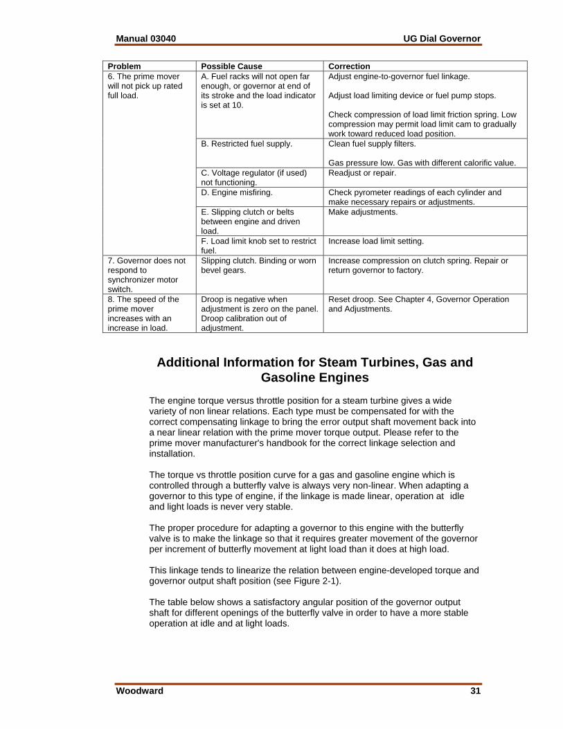
Table 5-1. Troubleshooting Chart Problem Possible Cause Correction
A. The problem may be originating in the governor or prime mover.
Block the throttle, fuel racks or steam valve in the direction of increase fuel. (Never block the governor output shaft in the direction that would prevent a complete shutdown.) The same blocking action can be performed by using the load limit knob on the governor panel. If hunting and/or surging continues while the governor output shaft is blocked, the problem is in the prime mover. If, after removing the block, hunting and/or surging starts again, the problem can be in the governor or in the prime mover. Go through the compensation adjustment procedure for the governor (see Chapter 4, Compensation Adjustments). If the problem is still there, replace the governor with a replacement governor. Go through the compensation adjustment procedure for the replacement governor. If the hunting and/or surging continues, the problem is in the prime mover.
B. Compensation adjustments incorrect.
Adjust needle valve and compensation adjusting pointer.
C. Dirty oil (sludge) in governor. Drain oil, clean governor, and refill. D. Oil varnish, which causes sticking of parts.
Add oil to the mark on oil sight glass. If oil level decreases and no external oil leaks can be seen on the governor, check the drive shaft for oil leak. If foaming continues, drain oil and refill using a different type oil.
E. Lost motion in engine linkage or fuel pumps.
Repair governor.
F. Lost motion in engine linkage or fuel pumps.
Repair linkage and/or pumps.
G. Binding in engine-to-governor linkage or fuel pumps.
Repair and realign linkage and/or pumps.
H. Governor output shaft travel too short to provide full fuel.
Adjust travel until proper travel is obtained.
1. The prime mover hunts or surges.
I. Spring on yield linkage to fuel racks too weak.
Install heavier spring.

Manual 03040 UG Dial Governor
Woodward 29
Problem Possible Cause Correction
J. Low oil pressure. Normal operating pressure is 758 to 827 kPa (110 to 120 psi) for the UG-5.7 and UG-8; 965 to 1034 kPa (140 to 150 psi) for the UG-10. (See outline drawing, Figure 1-3, for pressure test point location.) Pump check valves are not seating or accumulator springs weak.
Return governor to factory for repair.
K. Power piston is sticking. Check for side play or binding of output shaft. L. Voltage regulator not operating properly.
Check voltage regulator. Operate in voltage droop or manual. Do not disconnect voltage regulator. Adjust, repair, or replace voltage regulator.
M. Fuel linkage incorrectly set. This might occur if the governor has been changed or removed and replaced. Relationship of governor travel to power output of engine should be linear.
Rework or reset the linkage from governor to unit to obtain the linear relationship.
N. Faulty linkage. Linkage should be free of binding and lost motion throughout service life of unit. Check yield links, shutdown arrangements, etc, to be sure that prime mover torque changes for very small increments of governor output shaft travel. Stability and good steady-state performance will suffer unless this condition is met.
O. Incorrect non-linear relationship between governor travel and power output of the prime mover. Engine may hunt with light loads and be stable with a heavy load.
Adjust linkage from governor to gas valve to obtain linear relationship between governor travel and engine output. See Figure 2-1. Also, see application Note 50516.
P. Gas or steam pressure too high.
Adjust gas or steam pressure.
Q. Engine misfiring (bad fuel injector or low pilot fuel on dual-fuel engine).
Check pyrometer readings of each cylinder and make necessary repairs or adjustments.
R. Load limit indicator binding on nameplate or load limit shaft bent.
Damaged indicator disc or nameplate must be corrected or replaced. Load limit shaft must be replaced if bent.
S. Negative droop when speed droop knob at zero.
Droop calibration out of adjustment. Reset (see Chapter 4, Governor Operation and Adjustments).
1. The prime mover hunts or surges. (continued)
T. Governor worn. Return governor to factory for repairs. A. Low oil pressure in governor. See Item 1J. B. Cranking speed too low. May be necessary to use a booster servomotor. See
manual 36684, Booster Servomotor.
2. Fuel racks do not open quickly when cranking prime mover.
C. Booster servomotor (if used) not functioning properly.
Check action of automatic air starting valve. See manual 36684, Booster Servomotor.

UG Dial Governor Manual 03040
30 Woodward
Problem Possible Cause Correction
A. Rough engine drive or governor drive.
Inspect drive mechanism. a. Check alignment of gears. b. Inspect for rough gear teeth, eccentric gears, or excessive backlash in gear train. c. Check gear keys and nuts or set screws holding drive gears to shafts. d. Check for bent drive shaft. e. Check serrated or spline coupling for wear and alignment. f. Tighten chain between crankshaft and camshaft (if used). g. Check engine vibration damper (if used).
NOTE If a keyed drive is used, backlash must be checked and the gear shimmed so that there is no binding and the backlash is not too great. This should be done each time a new or replacement governor is installed. If a serrated drive is used, concentricity of shaft to coupling should be maintained. Coupling should be as long as possible to permit greater flexibility. B. Governor is not aligned properly.
Loosen governor mounting screws and move the governor slightly on its mounting pad to align the drive shaft with its coupling.
C. Failure of flexible drive in flyweight head.
Return governor to factory for repairs.
D. Other possible causes are: –dirty or worn ballhead bearing –rough or worn gear teeth –bent speeder spring –damaged drive shaft seal retainer
Return governor to factory for repairs. or Replace seal retainer.
3. Jiggle at governor output shaft.
E. Air in governor system can cause a jiggle during start-ups or transients.
Bleed air (see Chapter 4, Test Procedures).
A. Speed droop adjustment incorrect.
Readjust droop to divide load properly. Increase droop to resist picking up (or dropping off) load. Decrease droop to increase picking up (or dropping off) load.
4. Load does not divide properly on interconnected prime movers.
B. Speed settings of the governors are not the same.
Adjust speed setting so both prime movers run at the same speed.
A. Needle valve adjustment incorrect.
Readjust compensating needle valve. Open further if possible to do so without causing instability when running without load. Compensation pointer may be too far toward maximum.
B. Governor is not sensitive in measuring speed change (deadband).
Friction or wear on flyweight toes—sludge in governor, return to factory.
C. Low oil pressure in governor. Return governor to factory to inspect pump and check valves if oil pressure is low.
D. Engine may be overloaded. Reduce load. E. Restricted fuel supply. Clean fuel supply filters.
5. The prime mover is slow to respond to a speed change or a load change.
F. Load limit knob set to restrict fuel.
Increase load limit setting.
Manual 03040 UG Dial Governor
Woodward 31
Problem Possible Cause Correction
A. Fuel racks will not open far enough, or governor at end of its stroke and the load indicator is set at 10.
Adjust engine-to-governor fuel linkage. Adjust load limiting device or fuel pump stops. Check compression of load limit friction spring. Low compression may permit load limit cam to gradually work toward reduced load position.
B. Restricted fuel supply. Clean fuel supply filters. Gas pressure low. Gas with different calorific value.
C. Voltage regulator (if used) not functioning.
Readjust or repair.
D. Engine misfiring. Check pyrometer readings of each cylinder and make necessary repairs or adjustments.
E. Slipping clutch or belts between engine and driven load.
Make adjustments.
6. The prime mover will not pick up rated full load.
F. Load limit knob set to restrict fuel.
Increase load limit setting.
7. Governor does not respond to synchronizer motor switch.
Slipping clutch. Binding or worn bevel gears.
Increase compression on clutch spring. Repair or return governor to factory.
8. The speed of the prime mover increases with an increase in load.
Droop is negative when adjustment is zero on the panel. Droop calibration out of adjustment.
Reset droop. See Chapter 4, Governor Operation and Adjustments.
Additional Information for Steam Turbines, Gas and Gasoline Engines
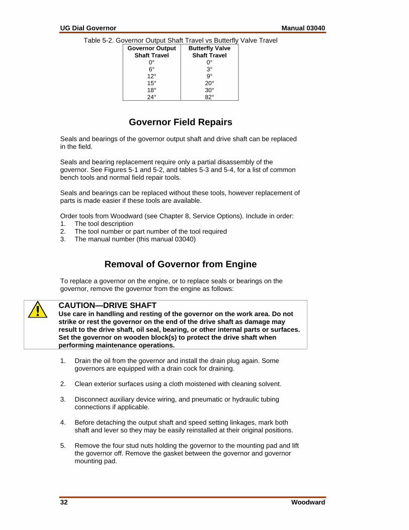
The engine torque versus throttle position for a steam turbine gives a wide variety of non linear relations. Each type must be compensated for with the correct compensating linkage to bring the error output shaft movement back into a near linear relation with the prime mover torque output. Please refer to the prime mover manufacturer's handbook for the correct linkage selection and installation. The torque vs throttle position curve for a gas and gasoline engine which is controlled through a butterfly valve is always very non-linear. When adapting a governor to this type of engine, if the linkage is made linear, operation at idle and light loads is never very stable. The proper procedure for adapting a governor to this engine with the butterfly valve is to make the linkage so that it requires greater movement of the governor per increment of butterfly movement at light load than it does at high load. This linkage tends to linearize the relation between engine-developed torque and governor output shaft position (see Figure 2-1). The table below shows a satisfactory angular position of the governor output shaft for different openings of the butterfly valve in order to have a more stable operation at idle and at light loads.
UG Dial Governor Manual 03040
32 Woodward
Table 5-2. Governor Output Shaft Travel vs Butterfly Valve Travel Governor Output
Shaft Travel 0° 6° 12° 15° 18° 24°
Butterfly Valve Shaft Travel
0° 3° 9° 20° 30° 82°
Governor Field Repairs Seals and bearings of the governor output shaft and drive shaft can be replaced in the field. Seals and bearing replacement require only a partial disassembly of the governor. See Figures 5-1 and 5-2, and tables 5-3 and 5-4, for a list of common bench tools and normal field repair tools. Seals and bearings can be replaced without these tools, however replacement of parts is made easier if these tools are available. Order tools from Woodward (see Chapter 8, Service Options). Include in order: 1. The tool description 2. The tool number or part number of the tool required 3. The manual number (this manual 03040)
Removal of Governor from Engine To replace a governor on the engine, or to replace seals or bearings on the governor, remove the governor from the engine as follows:
CAUTION—DRIVE SHAFT Use care in handling and resting of the governor on the work area. Do not strike or rest the governor on the end of the drive shaft as damage may result to the drive shaft, oil seal, bearing, or other internal parts or surfaces. Set the governor on wooden block(s) to protect the drive shaft when performing maintenance operations. 1. Drain the oil from the governor and install the drain plug again. Some
governors are equipped with a drain cock for draining. 2. Clean exterior surfaces using a cloth moistened with cleaning solvent. 3. Disconnect auxiliary device wiring, and pneumatic or hydraulic tubing
connections if applicable. 4. Before detaching the output shaft and speed setting linkages, mark both
shaft and lever so they may be easily reinstalled at their original positions. 5. Remove the four stud nuts holding the governor to the mounting pad and lift
the governor off. Remove the gasket between the governor and governor mounting pad.

Manual 03040 UG Dial Governor
Woodward 33
6. Set the governor on wooden blocks to protect the drive shaft. Be very careful to avoid striking the end of the drive shaft. Damage to internal parts of the governor may result.
Table 5-3. List of Common Bench Tools
Tool Description
Ref. Number
Tool Number
Application
T-handle hex wrench 7/16” T-handle Allen wrench 3/16” Standard Allen wrench 5/64” Bench block No. 2 Phillips head screwdriver Hooked scribe
1 2 3 4 5 6
189440 8995-047 8995-048 011971 8995-049 189792
Various bolts on UG To install 1/8” pipe plugs For No. 8:32 headless set screw To press out small bearings and bushings Various screws on UG Removing and installing cotter pins
Figure 5-1. Common Bench Tools

UG Dial Governor Manual 03040
34 Woodward
Table 5-4. List of Normal Field Repair Tools Tool Description
Ref. Number
Tool Number
Application
William pliers Bearing seater Seal protector (use with 030952) Dial indicator w/ base Seal installing tool (Micarta type) Bushing driver Serration wrench Torque wrench w/ 7/16” socket
7 8 9 10 11 12 13 14
8995-023 8995-024 030951 8995-017 030952 8995-028 030943 8995-038
Replace retaining ring on drive shaft Replace drive shaft bearing Fit on output shaft to protect seal To check droop adjustment Install output shaft seals (for extra long shafts only) To adjust output shaft bushings Turning output shaft or drive shaft 25 lb-in torque on drive shaft bearing retainer plate screws
Figure 5-2. Normal Field Repair Tools

Manual 03040 UG Dial Governor
Woodward 35
Chapter 6. Replacement Parts
Replacement Parts Information When ordering replacement parts, include the following information: • Governor serial number and part number shown on nameplate • Manual number (this is manual 03040) • Parts reference number in parts list and description of part or part name
WARNING—SPRINGS Refer to repair manual 56103 for correct and safe procedures when disassembly and assembly are required. Personal injury may result if accumulator springs are released suddenly. Use an arbor press to release or to install the compressed accumulator spring.
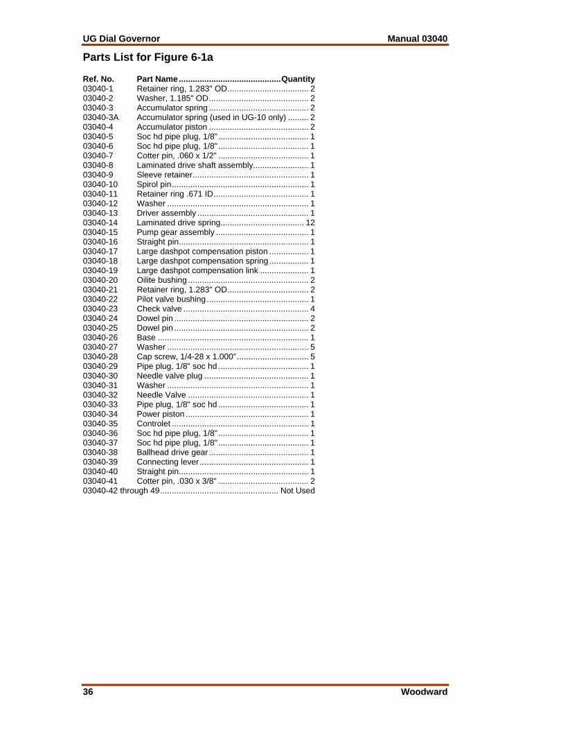
UG Dial Governor Manual 03040
36 Woodward
Parts List for Figure 6-1a Ref. No. Part Name............................................Quantity 03040-1 Retainer ring, 1.283" OD................................... 2 03040-2 Washer, 1.185" OD........................................... 2 03040-3 Accumulator spring ........................................... 2 03040-3A Accumulator spring (used in UG-10 only) ......... 2 03040-4 Accumulator piston ........................................... 2 03040-5 Soc hd pipe plug, 1/8"....................................... 1 03040-6 Soc hd pipe plug, 1/8"....................................... 1 03040-7 Cotter pin, .060 x 1/2" ....................................... 1 03040-8 Laminated drive shaft assembly........................ 1 03040-9 Sleeve retainer.................................................. 1 03040-10 Spirol pin........................................................... 1 03040-11 Retainer ring .671 ID......................................... 1 03040-12 Washer ............................................................. 1 03040-13 Driver assembly ................................................ 1 03040-14 Laminated drive spring.................................... 12 03040-15 Pump gear assembly ........................................ 1 03040-16 Straight pin........................................................ 1 03040-17 Large dashpot compensation piston ................. 1 03040-18 Large dashpot compensation spring ................. 1 03040-19 Large dashpot compensation link ..................... 1 03040-20 Oilite bushing .................................................... 2 03040-21 Retainer ring, 1.283" OD................................... 2 03040-22 Pilot valve bushing............................................ 1 03040-23 Check valve ...................................................... 4 03040-24 Dowel pin .......................................................... 2 03040-25 Dowel pin .......................................................... 2 03040-26 Base ................................................................. 1 03040-27 Washer ............................................................. 5 03040-28 Cap screw, 1/4-28 x 1.000”............................... 5 03040-29 Pipe plug, 1/8" soc hd ....................................... 1 03040-30 Needle valve plug ............................................. 1 03040-31 Washer ............................................................. 1 03040-32 Needle Valve .................................................... 1 03040-33 Pipe plug, 1/8" soc hd ....................................... 1 03040-34 Power piston ..................................................... 1 03040-35 Controlet ........................................................... 1 03040-36 Soc hd pipe plug, 1/8"....................................... 1 03040-37 Soc hd pipe plug, 1/8"....................................... 1 03040-38 Ballhead drive gear ........................................... 1 03040-39 Connecting lever............................................... 1 03040-40 Straight pin........................................................ 1 03040-41 Cotter pin, .030 x 3/8" ....................................... 2 03040-42 through 49................................................... Not Used
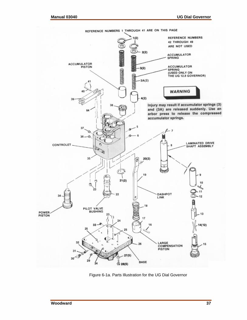
Manual 03040 UG Dial Governor
Woodward 37
Figure 6-1a. Parts Illustration for the UG Dial Governor

UG Dial Governor Manual 03040
38 Woodward
Parts List for Figure 6-1b Ref. No. Part Name............................................Quantity 03040-50 Plug .................................................................. 1 03040-51 Output shaft (optional) ...................................... 1 03040-52 Set screw, 1/4-28 x 5/16" .................................. 2 03040-53 Output shaft bushing......................................... 2 03040-54 Oil seal, 1.128 OD ............................................ 2 03040-54A Compensation adjustment lever pin stop .......... 2 03040-55 Washer, 7/16 x 5/8 x 1/32"................................ 1 03040-56 Compensation adj. pointer ................................ 1 03040-57 Washer, .328 x .562 x .064 thick....................... 1 03040-58 Elastic stop nut 5/16-24 .................................... 1 03040-59 Keyed drive shaft .............................................. 1 03040-60 Key .188 x .190 x 1.062" ................................... 1 03040-61 Spacer .............................................................. 1 03040-62 Nut, 5/8-18 castle.............................................. 1 03040-63 Cotter pin, 1/8 x 1-1/2" ...................................... 1 03040-64 Pilot valve plunger ............................................ 1 03040-65 Spring seat........................................................ 1 03040-66 Pilot valve spring............................................... 1 03040-67 Drive shaft......................................................... 1 03040-68 Ball bearing....................................................... 1 03040-69 Snap ring .......................................................... 1 03040-70 Bearing retainer plate........................................ 1 03040-71 Dr hd cap screw, 1/4-28 x 5/8".......................... 3 03040-72 Oil seal, 1.379" OD ........................................... 1 03040-73 Oil seal retainer................................................. 1 03040-74 Seal retainer gasket .......................................... 1 03040-75 Small dashpot compensation piston assembly . 1 03040-76 Small dashpot compensation spring ................. 2 03040-77 Small dashpot spring seat (not shown) ............. 1 03040-78 Small dashpot compensation piston guide........ 1 03040-79 Hex lock nut, 1/4-28.......................................... 1 03040-80 Dashpot nut ...................................................... 1 03040-81 Shutdown lever bracket .................................... 1 03040-82 Spring ............................................................... 1 03040-83 Washer, .178 ID................................................ 1 03040-84 Cotter pin .......................................................... 1 03040-85 Headed pin ....................................................... 1 03040-86 Shutdown lever ................................................. 1 03040-87 Washer ............................................................. 2 03040-88 Screw................................................................ 2 03040-89 Cotter pin .......................................................... 1 03040-90 Washer ............................................................. 1 03040-91 Power piston link............................................... 1 03040-92 Cotter pin .......................................................... 1 03040-93 Power lever....................................................... 1 03040-94 Taper pin, No.3 x 1-1/4".................................... 2 03040-95 Pin .................................................................... 1 03040-96 Cotter pin, .060 x 3/4" ....................................... 1 03040-97 Compensation lever .......................................... 1 03040-98 Straight pin........................................................ 1 03040-99 Drilled straight pin ............................................. 1 03040-100 Cotter pin, .060 x 3/4" ....................................... 1 03040-101 Straight pin........................................................ 1 03040-102 Compensation link ............................................ 1 03040-103 Compensation lever fulcrum ............................. 1 03040-104 Compensation lever assembly.......................... 1 03040-105 Preformed Packing Ring, .301 1 D x .070"........ 1 03040-106 Case ................................................................. 1 03040-107 Output shaft ...................................................... 1 03040-108 through 149............................................... Not Used

Manual 03040 UG Dial Governor
Woodward 39
Figure 6-1b. Parts Illustration for the UG Dial Governor
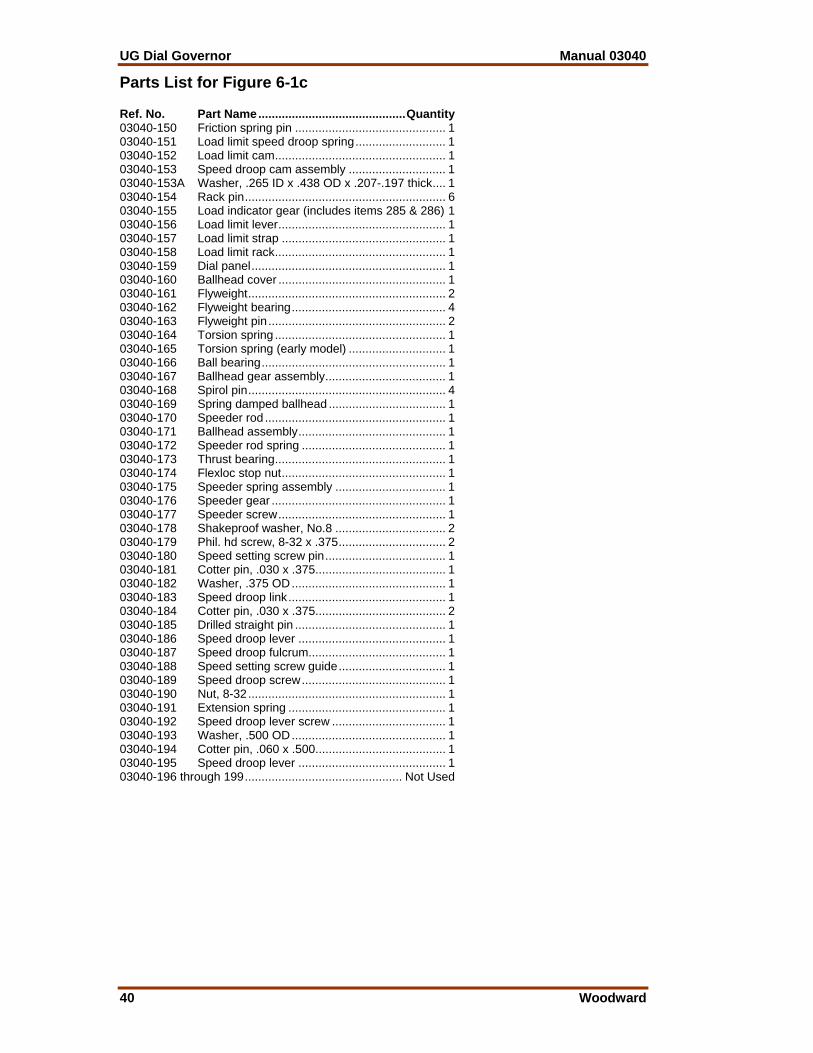
UG Dial Governor Manual 03040
40 Woodward
Parts List for Figure 6-1c Ref. No. Part Name............................................Quantity 03040-150 Friction spring pin ............................................. 1 03040-151 Load limit speed droop spring........................... 1 03040-152 Load limit cam................................................... 1 03040-153 Speed droop cam assembly ............................. 1 03040-153A Washer, .265 ID x .438 OD x .207-.197 thick.... 1 03040-154 Rack pin............................................................ 6 03040-155 Load indicator gear (includes items 285 & 286) 1 03040-156 Load limit lever.................................................. 1 03040-157 Load limit strap ................................................. 1 03040-158 Load limit rack................................................... 1 03040-159 Dial panel.......................................................... 1 03040-160 Ballhead cover .................................................. 1 03040-161 Flyweight........................................................... 2 03040-162 Flyweight bearing.............................................. 4 03040-163 Flyweight pin ..................................................... 2 03040-164 Torsion spring ................................................... 1 03040-165 Torsion spring (early model) ............................. 1 03040-166 Ball bearing....................................................... 1 03040-167 Ballhead gear assembly.................................... 1 03040-168 Spirol pin........................................................... 4 03040-169 Spring damped ballhead ................................... 1 03040-170 Speeder rod ...................................................... 1 03040-171 Ballhead assembly............................................ 1 03040-172 Speeder rod spring ........................................... 1 03040-173 Thrust bearing................................................... 1 03040-174 Flexloc stop nut................................................. 1 03040-175 Speeder spring assembly ................................. 1 03040-176 Speeder gear .................................................... 1 03040-177 Speeder screw.................................................. 1 03040-178 Shakeproof washer, No.8 ................................. 2 03040-179 Phil. hd screw, 8-32 x .375................................ 2 03040-180 Speed setting screw pin.................................... 1 03040-181 Cotter pin, .030 x .375....................................... 1 03040-182 Washer, .375 OD.............................................. 1 03040-183 Speed droop link............................................... 1 03040-184 Cotter pin, .030 x .375....................................... 2 03040-185 Drilled straight pin ............................................. 1 03040-186 Speed droop lever ............................................ 1 03040-187 Speed droop fulcrum......................................... 1 03040-188 Speed setting screw guide................................ 1 03040-189 Speed droop screw........................................... 1 03040-190 Nut, 8-32........................................................... 1 03040-191 Extension spring ............................................... 1 03040-192 Speed droop lever screw .................................. 1 03040-193 Washer, .500 OD.............................................. 1 03040-194 Cotter pin, .060 x .500....................................... 1 03040-195 Speed droop lever ............................................ 1 03040-196 through 199............................................... Not Used

Manual 03040 UG Dial Governor
Woodward 41
Figure 6-1c. Parts Illustration for the UG Dial Governor
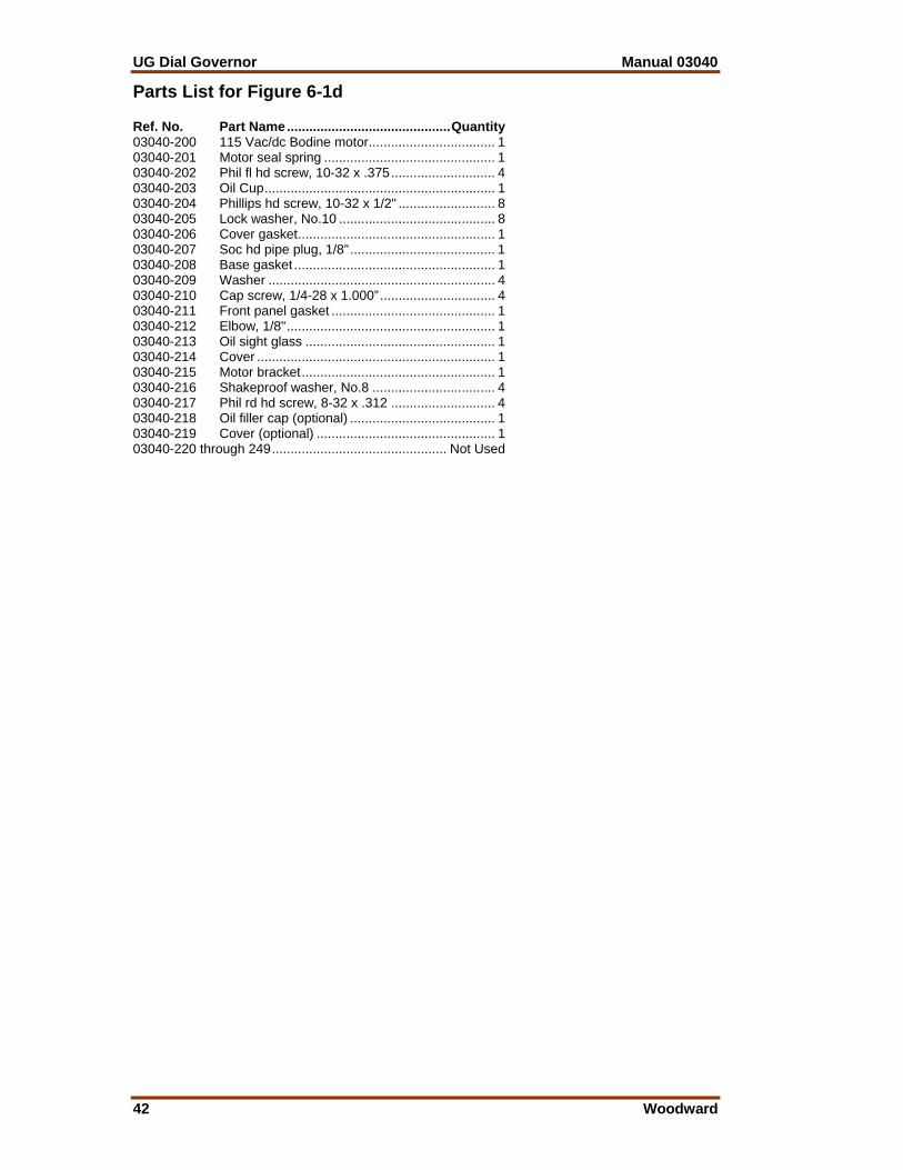
UG Dial Governor Manual 03040
42 Woodward
Parts List for Figure 6-1d Ref. No. Part Name............................................Quantity 03040-200 115 Vac/dc Bodine motor.................................. 1 03040-201 Motor seal spring .............................................. 1 03040-202 Phil fl hd screw, 10-32 x .375............................ 4 03040-203 Oil Cup.............................................................. 1 03040-204 Phillips hd screw, 10-32 x 1/2" .......................... 8 03040-205 Lock washer, No.10 .......................................... 8 03040-206 Cover gasket..................................................... 1 03040-207 Soc hd pipe plug, 1/8"....................................... 1 03040-208 Base gasket ...................................................... 1 03040-209 Washer ............................................................. 4 03040-210 Cap screw, 1/4-28 x 1.000”............................... 4 03040-211 Front panel gasket ............................................ 1 03040-212 Elbow, 1/8"........................................................ 1 03040-213 Oil sight glass ................................................... 1 03040-214 Cover ................................................................ 1 03040-215 Motor bracket.................................................... 1 03040-216 Shakeproof washer, No.8 ................................. 4 03040-217 Phil rd hd screw, 8-32 x .312 ............................ 4 03040-218 Oil filler cap (optional) ....................................... 1 03040-219 Cover (optional) ................................................ 1 03040-220 through 249............................................... Not Used

Manual 03040 UG Dial Governor
Woodward 43
Figure 6-1d. Parts Illustration for the UG Dial Governor
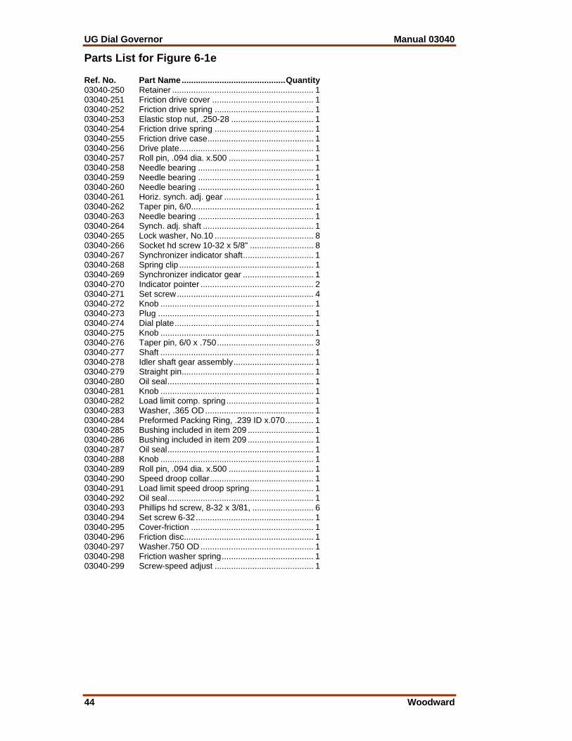
UG Dial Governor Manual 03040
44 Woodward
Parts List for Figure 6-1e Ref. No. Part Name............................................Quantity 03040-250 Retainer ............................................................ 1 03040-251 Friction drive cover ........................................... 1 03040-252 Friction drive spring .......................................... 1 03040-253 Elastic stop nut, .250-28 ................................... 1 03040-254 Friction drive spring .......................................... 1 03040-255 Friction drive case............................................. 1 03040-256 Drive plate......................................................... 1 03040-257 Roll pin, .094 dia. x.500 .................................... 1 03040-258 Needle bearing ................................................. 1 03040-259 Needle bearing ................................................. 1 03040-260 Needle bearing ................................................. 1 03040-261 Horiz. synch. adj. gear ...................................... 1 03040-262 Taper pin, 6/0.................................................... 1 03040-263 Needle bearing ................................................. 1 03040-264 Synch. adj. shaft ............................................... 1 03040-265 Lock washer, No.10 .......................................... 8 03040-266 Socket hd screw 10-32 x 5/8" ........................... 8 03040-267 Synchronizer indicator shaft.............................. 1 03040-268 Spring clip ......................................................... 1 03040-269 Synchronizer indicator gear .............................. 1 03040-270 Indicator pointer ................................................ 2 03040-271 Set screw.......................................................... 4 03040-272 Knob ................................................................. 1 03040-273 Plug .................................................................. 1 03040-274 Dial plate........................................................... 1 03040-275 Knob ................................................................. 1 03040-276 Taper pin, 6/0 x .750......................................... 3 03040-277 Shaft ................................................................. 1 03040-278 Idler shaft gear assembly.................................. 1 03040-279 Straight pin........................................................ 1 03040-280 Oil seal.............................................................. 1 03040-281 Knob ................................................................. 1 03040-282 Load limit comp. spring ..................................... 1 03040-283 Washer, .365 OD.............................................. 1 03040-284 Preformed Packing Ring, .239 ID x.070............ 1 03040-285 Bushing included in item 209 ............................ 1 03040-286 Bushing included in item 209 ............................ 1 03040-287 Oil seal.............................................................. 1 03040-288 Knob ................................................................. 1 03040-289 Roll pin, .094 dia. x.500 .................................... 1 03040-290 Speed droop collar............................................ 1 03040-291 Load limit speed droop spring........................... 1 03040-292 Oil seal.............................................................. 1 03040-293 Phillips hd screw, 8-32 x 3/81, .......................... 6 03040-294 Set screw 6-32.................................................. 1 03040-295 Cover-friction .................................................... 1 03040-296 Friction disc....................................................... 1 03040-297 Washer.750 OD................................................ 1 03040-298 Friction washer spring....................................... 1 03040-299 Screw-speed adjust .......................................... 1
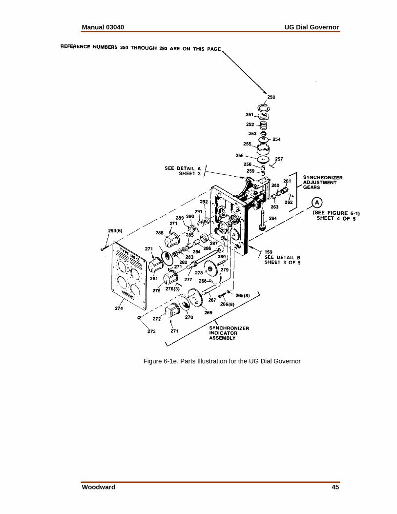
Manual 03040 UG Dial Governor
Woodward 45
Figure 6-1e. Parts Illustration for the UG Dial Governor
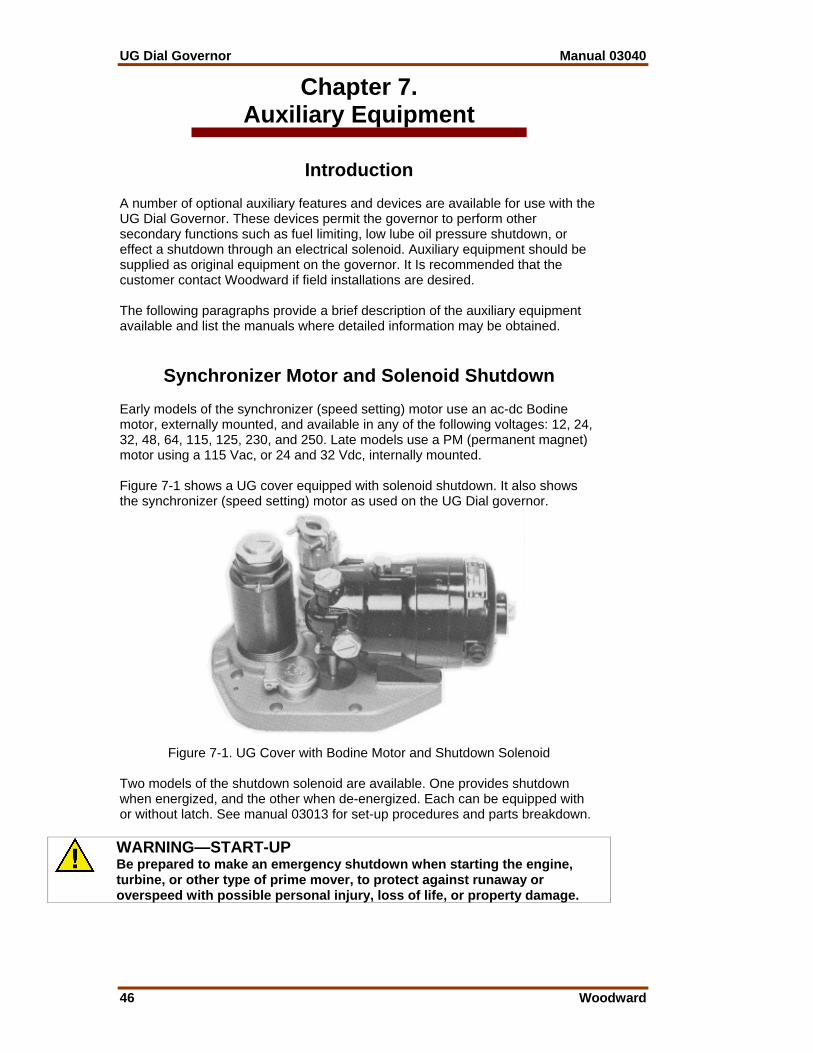
UG Dial Governor Manual 03040
46 Woodward
Chapter 7. Auxiliary Equipment
Introduction A number of optional auxiliary features and devices are available for use with the UG Dial Governor. These devices permit the governor to perform other secondary functions such as fuel limiting, low lube oil pressure shutdown, or effect a shutdown through an electrical solenoid. Auxiliary equipment should be supplied as original equipment on the governor. It Is recommended that the customer contact Woodward if field installations are desired. The following paragraphs provide a brief description of the auxiliary equipment available and list the manuals where detailed information may be obtained.
Synchronizer Motor and Solenoid Shutdown Early models of the synchronizer (speed setting) motor use an ac-dc Bodine motor, externally mounted, and available in any of the following voltages: 12, 24, 32, 48, 64, 115, 125, 230, and 250. Late models use a PM (permanent magnet) motor using a 115 Vac, or 24 and 32 Vdc, internally mounted. Figure 7-1 shows a UG cover equipped with solenoid shutdown. It also shows the synchronizer (speed setting) motor as used on the UG Dial governor.
Figure 7-1. UG Cover with Bodine Motor and Shutdown Solenoid
Two models of the shutdown solenoid are available. One provides shutdown when energized, and the other when de-energized. Each can be equipped with or without latch. See manual 03013 for set-up procedures and parts breakdown.
WARNING—START-UP Be prepared to make an emergency shutdown when starting the engine, turbine, or other type of prime mover, to protect against runaway or overspeed with possible personal injury, loss of life, or property damage.
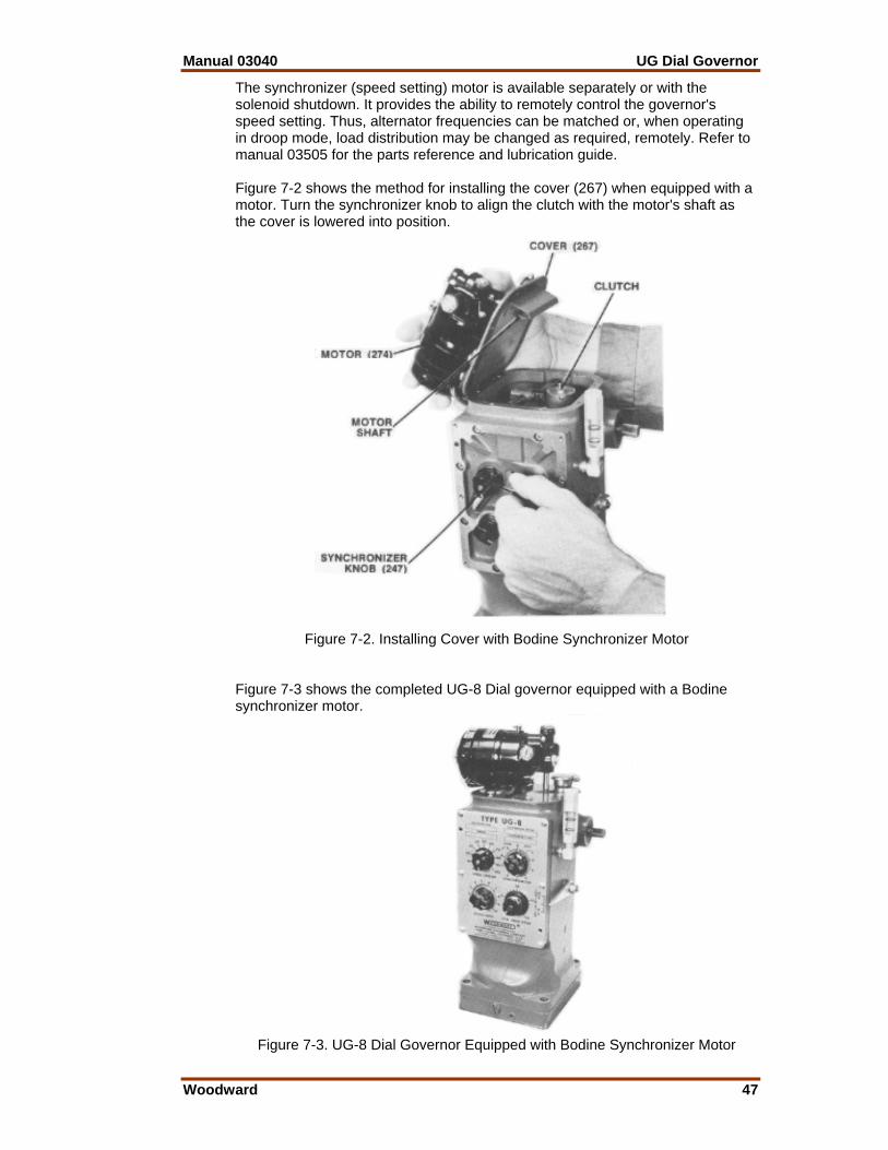
Manual 03040 UG Dial Governor
Woodward 47
The synchronizer (speed setting) motor is available separately or with the solenoid shutdown. It provides the ability to remotely control the governor's speed setting. Thus, alternator frequencies can be matched or, when operating in droop mode, load distribution may be changed as required, remotely. Refer to manual 03505 for the parts reference and lubrication guide. Figure 7-2 shows the method for installing the cover (267) when equipped with a motor. Turn the synchronizer knob to align the clutch with the motor's shaft as the cover is lowered into position.
Figure 7-2. Installing Cover with Bodine Synchronizer Motor
Figure 7-3 shows the completed UG-8 Dial governor equipped with a Bodine synchronizer motor.
Figure 7-3. UG-8 Dial Governor Equipped with Bodine Synchronizer Motor

UG Dial Governor Manual 03040
48 Woodward
PM Synchronizer Motor with Housing Figure 7-4 shows a UG-8 Dial governor with a permanent magnet synchronizer motor (speed setting motor) and a shutdown solenoid, enclosed in a weatherproof housing. At rest, the permanent magnet motor acts as a brake to resist speed changes due to vibrations. The weatherproof housing for the PM synchronizer motor can also be equipped with a shutdown solenoid. There are several supply voltages available for the solenoid. Contact Woodward for additional information. A conduit connection and a pin-type connector are also available.
Figure 7-4. Top View of Weatherproof Housing with PM Synchronizer Motor and
Shutdown Solenoid Figure 7-5 shows the UG-8 governor with PM motor and weatherproof housing.
Figure 7-5. UG-8 Governor with PM Motor, Shutdown Weatherproof Housing
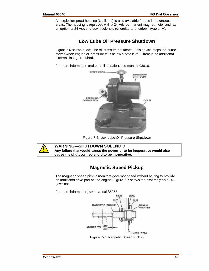
Manual 03040 UG Dial Governor
Woodward 49
An explosion-proof housing (UL listed) is also available for use in hazardous areas. The housing is equipped with a 24 Vdc permanent magnet motor and, as an option, a 24 Vdc shutdown solenoid (energize-to-shutdown type only).
Low Lube Oil Pressure Shutdown Figure 7-6 shows a low lube oil pressure shutdown. This device stops the prime mover when engine oil pressure falls below a safe level. There is no additional external linkage required. For more information and parts illustration, see manual 03016.
Figure 7-6. Low Lube Oil Pressure Shutdown
WARNING—SHUTDOWN SOLENOID Any failure that would cause the governor to be inoperative would also cause the shutdown solenoid to be inoperative.
Magnetic Speed Pickup The magnetic speed pickup monitors governor speed without having to provide an additional drive pad on the engine. Figure 7-7 shows the assembly on a UG governor. For more information, see manual 36052.
Figure 7-7. Magnetic Speed Pickup
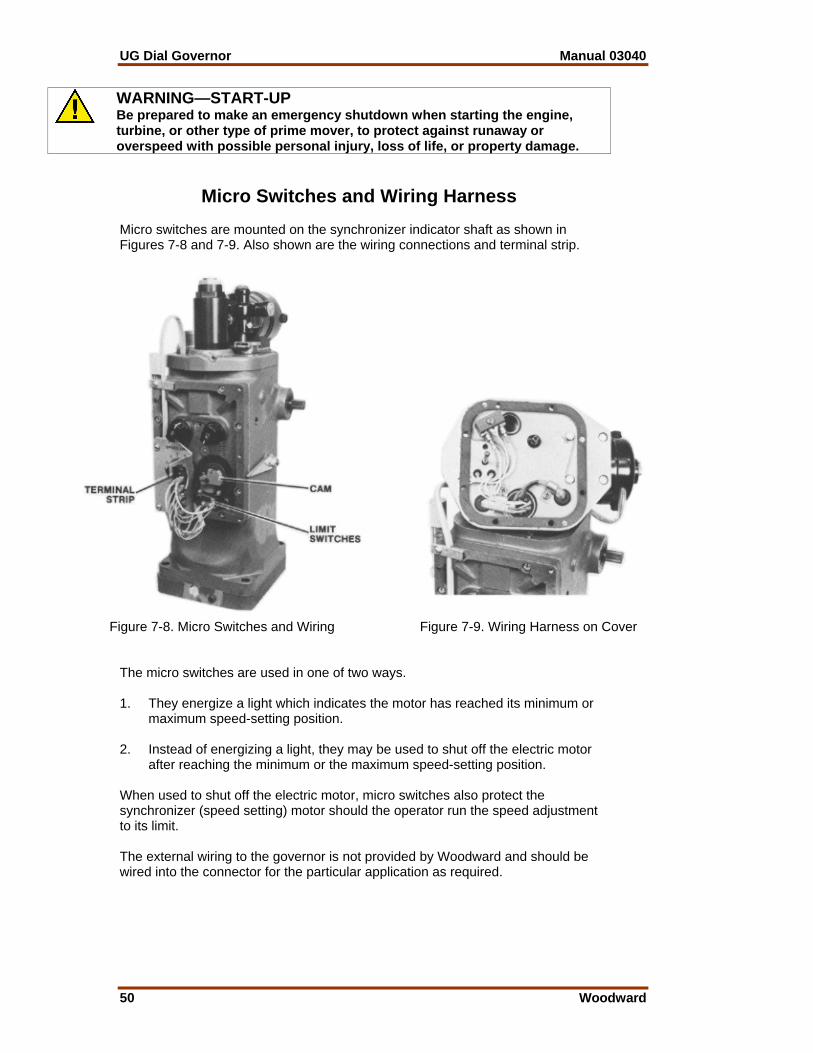
UG Dial Governor Manual 03040
50 Woodward
WARNING—START-UP Be prepared to make an emergency shutdown when starting the engine, turbine, or other type of prime mover, to protect against runaway or overspeed with possible personal injury, loss of life, or property damage.
Micro Switches and Wiring Harness Micro switches are mounted on the synchronizer indicator shaft as shown in Figures 7-8 and 7-9. Also shown are the wiring connections and terminal strip.
Figure 7-8. Micro Switches and Wiring
Figure 7-9. Wiring Harness on Cover The micro switches are used in one of two ways. 1. They energize a light which indicates the motor has reached its minimum or
maximum speed-setting position. 2. Instead of energizing a light, they may be used to shut off the electric motor
after reaching the minimum or the maximum speed-setting position. When used to shut off the electric motor, micro switches also protect the synchronizer (speed setting) motor should the operator run the speed adjustment to its limit. The external wiring to the governor is not provided by Woodward and should be wired into the connector for the particular application as required.
Manual 03040 UG Dial Governor
Woodward 51
Chapter 8. Service Options
Product Service Options The following factory options are available for servicing Woodward equipment, based on the standard Woodward Product and Service Warranty (5-01-1205) that is in effect at the time the product is purchased from Woodward or the service is performed: • Replacement/Exchange (24-hour service) • Flat Rate Repair • Flat Rate Remanufacture If you are experiencing problems with installation or unsatisfactory performance of an installed system, the following options are available: • Consult the troubleshooting guide in the manual. • Contact Woodward technical assistance (see “How to Contact Woodward”
later in this chapter) and discuss your problem. In most cases, your problem can be resolved over the phone. If not, you can select which course of action you wish to pursue based on the available services listed in this section.
Replacement/Exchange Replacement/Exchange is a premium program designed for the user who is in need of immediate service. It allows you to request and receive a like-new replacement unit in minimum time (usually within 24 hours of the request), providing a suitable unit is available at the time of the request, thereby minimizing costly downtime. This is also a flat rate structured program and includes the full standard Woodward product warranty (Woodward Product and Service Warranty 5-01-1205). This option allows you to call in the event of an unexpected outage, or in advance of a scheduled outage, to request a replacement control unit. If the unit is available at the time of the call, it can usually be shipped out within 24 hours. You replace your field control unit with the like-new replacement and return the field unit to the Woodward facility as explained below (see “Returning Equipment for Repair” later in this chapter). Charges for the Replacement/Exchange service are based on a flat rate plus shipping expenses. You are invoiced the flat rate replacement/exchange charge plus a core charge at the time the replacement unit is shipped. If the core (field unit) is returned to Woodward within 60 days, Woodward will issue a credit for the core charge. [The core charge is the average difference between the flat rate replacement/exchange charge and the current list price of a new unit.] Return Shipment Authorization Label. To ensure prompt receipt of the core, and avoid additional charges, the package must be properly marked. A return authorization label is included with every Replacement/Exchange unit that leaves Woodward. The core should be repackaged and the return authorization label affixed to the outside of the package. Without the authorization label, receipt of the returned core could be delayed and cause additional charges to be applied.
UG Dial Governor Manual 03040
52 Woodward
Flat Rate Repair Flat Rate Repair is available for the majority of standard products in the field. This program offers you repair service for your products with the advantage of knowing in advance what the cost will be. All repair work carries the standard Woodward service warranty (Woodward Product and Service Warranty 5-01-1205) on replaced parts and labor. Flat Rate Remanufacture Flat Rate Remanufacture is very similar to the Flat Rate Repair option with the exception that the unit will be returned to you in “like-new” condition and carry with it the full standard Woodward product warranty (Woodward Product and Service Warranty 5-01-1205). This option is applicable to mechanical products only.
Returning Equipment for Repair If a control (or any part of an electronic control) is to be returned to Woodward for repair, please contact Woodward in advance to obtain a Return Authorization Number. When shipping the item(s), attach a tag with the following information: • name and location where the control is installed; • name and phone number of contact person; • complete Woodward part number(s) and serial number(s); • description of the problem; • instructions describing the desired type of repair.
CAUTION—ELECTROSTATIC DISCHARGE To prevent damage to electronic components caused by improper handling, read and observe the precautions in Woodward manual 82715, Guide for Handling and Protection of Electronic Controls, Printed Circuit Boards, and Modules. Packing a Control Use the following materials when returning a complete control: • protective caps on any connectors; • antistatic protective bags on all electronic modules; • packing materials that will not damage the surface of the unit; • at least 100 mm (4 inches) of tightly packed, industry-approved packing
material; • a packing carton with double walls; • a strong tape around the outside of the carton for increased strength.
Manual 03040 UG Dial Governor
Woodward 53
Return Authorization Number When returning equipment to Woodward, please telephone and ask for the Customer Service Department [1 (800) 523-2831 in North America or +1 (970) 482-5811]. They will help expedite the processing of your order through our distributors or local service facility. To expedite the repair process, contact Woodward in advance to obtain a Return Authorization Number, and arrange for issue of a purchase order for the item(s) to be repaired. No work can be started until a purchase order is received.
NOTE We highly recommend that you make arrangement in advance for return shipments. Contact a Woodward customer service representative at 1 (800) 523-2831 in North America or +1 (970) 482-5811 for instructions and for a Return Authorization Number.
Replacement Parts When ordering replacement parts for controls, include the following information: • the part number(s) (XXXX-XXXX) that is on the enclosure nameplate; • the unit serial number, which is also on the nameplate.
How to Contact Woodward In North America use the following address when shipping or corresponding: Woodward Governor Company PO Box 1519 1000 East Drake Rd Fort Collins CO 80522-1519, USA Telephone—+1 (970) 482-5811 (24 hours a day) Toll-free Phone (in North America)—1 (800) 523-2831 Fax—+1 (970) 498-3058 For assistance outside North America, call one of the following international Woodward facilities to obtain the address and phone number of the facility nearest your location where you will be able to get information and service. Facility Phone Number Brazil +55 (19) 3708 4800 India +91 (129) 230 7111 Japan +81 (476) 93-4661 The Netherlands +31 (23) 5661111 You can also contact the Woodward Customer Service Department or consult our worldwide directory on Woodward’s website (www.woodward.com) for the name of your nearest Woodward distributor or service facility.

UG Dial Governor Manual 03040
54 Woodward
Engineering Services Woodward Industrial Controls Engineering Services offers the following after-sales support for Woodward products. For these services, you can contact us by telephone, by email, or through the Woodward website. • Technical Support • Product Training • Field Service Contact information: Telephone—+1 (970) 482-5811 Toll-free Phone (in North America)—1 (800) 523-2831 Email—[email protected] Website—www.woodward.com Technical Support is available through our many worldwide locations or our authorized distributors, depending upon the product. This service can assist you with technical questions or problem solving during normal business hours. Emergency assistance is also available during non-business hours by phoning our toll-free number and stating the urgency of your problem. For technical support, please contact us via telephone, email us, or use our website and reference Customer Services and then Technical Support. Product Training is available at many of our worldwide locations (standard classes). We also offer customized classes, which can be tailored to your needs and can be held at one of our locations or at your site. This training, conducted by experienced personnel, will assure that you will be able to maintain system reliability and availability. For information concerning training, please contact us via telephone, email us, or use our website and reference Customer Services and then Product Training. Field Service engineering on-site support is available, depending on the product and location, from one of our many worldwide locations or from one of our authorized distributors. The field engineers are experienced both on Woodward products as well as on much of the non-Woodward equipment with which our products interface. For field service engineering assistance, please contact us via telephone, email us, or use our website and reference Customer Services and then Technical Support.

Manual 03040 UG Dial Governor
Woodward 55
Technical Assistance If you need to telephone for technical assistance, you will need to provide the following information. Please write it down here before phoning: General Your Name Site Location Phone Number Fax Number Prime Mover Information Engine/Turbine Model Number Manufacturer Number of Cylinders (if applicable) Type of Fuel (gas, gaseous, steam, etc) Rating Application Control/Governor Information Please list all Woodward governors, actuators, and electronic controls in your system: Woodward Part Number and Revision Letter Control Description or Governor Type Serial Number Woodward Part Number and Revision Letter Control Description or Governor Type Serial Number Woodward Part Number and Revision Letter Control Description or Governor Type Serial Number If you have an electronic or programmable control, please have the adjustment setting positions or the menu settings written down and with you at the time of the call.

UG Dial Governor Manual 03040
56 Woodward


We appreciate your comments about the content of our publications.
Send comments to: [email protected]
Please include the manual number from the front cover of this publication.
PO Box 1519, Fort Collins CO 80522-1519, USA 1000 East Drake Road, Fort Collins CO 80525, USA Phone +1 (970) 482-5811 • Fax +1 (970) 498-3058
Email and Website—www.woodward.com
Woodward has company-owned plants, subsidiaries, and branches, as well as authorized distributors and other authorized service and sales facilities throughout the world.
Complete address / phone / fax / email information for all locations is available on our website.
06/3/F