ufmc waveform and multiple-access techniques for 5g radcom
TRANSCRIPT

HAL Id: hal-03191682https://hal.archives-ouvertes.fr/hal-03191682v2
Submitted on 29 Apr 2021
HAL is a multi-disciplinary open accessarchive for the deposit and dissemination of sci-entific research documents, whether they are pub-lished or not. The documents may come fromteaching and research institutions in France orabroad, or from public or private research centers.
L’archive ouverte pluridisciplinaire HAL, estdestinée au dépôt et à la diffusion de documentsscientifiques de niveau recherche, publiés ou non,émanant des établissements d’enseignement et derecherche français ou étrangers, des laboratoirespublics ou privés.
UFMC Waveform and Multiple-Access Techniques for5G RadCom
Imane Khelouani, Kawtar Zerhouni, Fouzia Elbahhar, Raja Elassali,Noureddine Idboufker
To cite this version:Imane Khelouani, Kawtar Zerhouni, Fouzia Elbahhar, Raja Elassali, Noureddine Idboufker. UFMCWaveform and Multiple-Access Techniques for 5G RadCom. Electronics, MDPI, 2021, 10 (7), pp1-19.�10.3390/electronics10070849�. �hal-03191682v2�

electronics
Article
UFMC Waveform and Multiple-Access Techniques for5G RadCom
Imane Khelouani 1,2,* , Kawtar Zerhouni 2, Fouzia Elbahhar 2,*, Raja Elassali 1 and Noureddine Idboufker 1
�����������������
Citation: Khelouani, I.; Zerhouni, K.;
Elbahhar, F.; Elassali, R.; Idboufker, N.
UFMC Waveform and Multiple
Access Techniques for 5G RadCom.
Electronics 2021, 10, 849. https://
doi.org/10.3390/electronics10070849
Academic Editor: Krzysztof S. Kulpa
Received: 2 March 2021
Accepted: 31 March 2021
Published: 2 April 2021
Publisher’s Note: MDPI stays neutral
with regard to jurisdictional claims in
published maps and institutional affil-
iations.
Copyright: © 2021 by the authors.
Licensee MDPI, Basel, Switzerland.
This article is an open access article
distributed under the terms and
conditions of the Creative Commons
Attribution (CC BY) license (https://
creativecommons.org/licenses/by/
4.0/).
1 SSA, ENSA, University of Cadi Ayyad, 40000 Marrakech, Morocco; [email protected] (R.E.);[email protected] (N.I.)
2 COSYS-LEOST, University Gustave Eiffel, IFSTTAR, University Lille, F-59650 Villeneuve d’Ascq, France;[email protected]
* Correspondence: [email protected] (I.K.); [email protected] (F.E.)
Abstract: In recent years, multiple functions traditionally realized by hardware components havebeen replaced by digital-signal processing, making radar and wireless communication technologiesmore similar. A joint radar and communication system, referred to as a RadCom system, wasproposed to overcome the drawbacks of the conventional existent radar techniques while using thesame system for intervehicular communication. Consequently, this system enhances used spectralresources. Conventional orthogonal frequency division multiplexing (OFDM) was proposed asa RadCom waveform. However, due to OFDM’s multiple shortcomings, we propose universalfiltered multicarrier (UFMC), a new 5G waveform candidate, as a RadCom waveform that offers agood trade-off between performance and complexity. In addition to that, we propose multicarriercode division multiple access (MC-CDMA) as a multiple-access (MA) technique that can offer greatperformance in terms of multiuser detection and power efficiency. Moreover, we study how UFMCfilter length and MC-CDMA spreading sequences can impact overall performance on both radarand communication separately under a multipath channel. Analysis of the bit error rate (BER) of theUFMC waveform was performed in order to confirm the experiment results.
Keywords: OFDM RadCom; UFMC RadCom; UFMC-CDMA multiple access RadCom; TDL-Achannel; BER
1. Introduction
In recent years, either dedicated or cellular-based communication standards weredeveloped across the globe to enable vehicular communication. Whatever the choice, stan-dardization bodies keep in mind that vehicular communication has stringent requirements.Therefore, the frequency range was recommended by the International TelecommunicationUnion (ITU) [1] to be in the range of 76–81 GHz in order to meet appropriate wirelesssolutions for automotive RadCom systems.
The concept of a RadCom system has been investigated since the early 2000s. How-ever, combining two systems with different needs is not straightforward. Classical radarwaveform designs aim at creating waveforms with optimal autocorrelation properties tominimize sidelobe levels in distance estimation, hence reducing its estimation errors. Oneof the most popular signals achieving such a property are linear frequency modulatedpulses also known as “chirp” signals. Designing a RadCom system on this basis, however,heavily degrades the symbol rate, which is important for communication systems [2].
To accommodate the needs of both systems, the use of multicarrier signals was pro-posed by Levanon in 2000 [3] and 2002 [4]. Compared to single carriers, which haveonly one dimension time domain, multicarrier waveforms are two dimensional systemswhere both time and frequency are used efficiently. This frequency diversity appealedto many other researchers who proposed to adopt orthogonal frequency division multi-plexing (OFDM) as a RadCom waveform in [5,6]. The main advancements of this concept
Electronics 2021, 10, 849. https://doi.org/10.3390/electronics10070849 https://www.mdpi.com/journal/electronics

Electronics 2021, 10, 849 2 of 19
were proposed later on by Strum and al. and published in their invited paper [7] in 2011.In their previous paper, the authors focused on the use of OFDM RadCom systems forvehicular applications. In fact, OFDM-based signals can easily provide the range andvelocity estimation of targets surrounding the transmitter while offering robustness againstmultipath fading and simple equalization for communicating targets. However, OFDM isvery sensitive to the Doppler shift, which can cause intercarrier interference (ICI), therebydeteriorating the communication aspect of the RadCom system. In addition, OFDM radarsystems require a high cyclic prefix (CP) padded to the transmitted signal to preserve thetime orthogonality of the modulation symbols and prevent intersymbol interference (ISI),but at the cost of reduced spectral efficiency since the CP part of the signal is not used foreither detection or communication.
In order to overcome the shortcomings of CP-OFDM, multiple candidate waveformsfor 5G were investigated over the course of the past few years. To relax the orthogonalitycondition, they rely on different designs of synthesis functions. Universal filtered multi-carrier (UFMC) is one of the most attractive 5G waveforms candidates, and it was firstintroduced in [8]. It offers a good trade-off between performance and complexity, andit is suitable for supporting multiple services [9,10]. Applying filtering per groups ofsubcarriers [11] (namely, sub-bands), UFMC achieves low out-of-band (OOB) emissionswhile keeping the simplicity of OFDM [12]. In fact, UFMC decomposes the frequencyspectrum into narrow-band orthogonal subcarriers in the complex plane, making use ofstraightforward OFDM knowledge [12]. More specifically, in the UFMC scheme, the entireband of subcarriers Nc is subdivided into S sub-bands, with Q subcarriers each, such thatS × Q ≤ Nc. Each sub-band is then filtered by a prototype filter of length L and shifted tothe appropriate sub-band frequency [11]. As long as the same length of sub-band filter isused [12], subcarriers in UFMC are orthogonal in the complex plane. Hence, UFMC canuse quadrature amplitude modulation (QAM) constellation.
Moreover, a RadCom system must be able to operate over a multiuser V2X communi-cation scenario; hence, the need for multiple-access techniques imposes itself. The use ofcode division multiple access (CDMA) with direct-sequence spread spectrum (DS-CDMA)was proposed in 2015 [13] and earlier in 2006 in [14]. This technique proved to have greatrange and velocity estimation while allowing for multiple users to share the same time–frequency resource using unique orthogonal codes. However, the conventional DS-CDMAspreads user data to a short-duration chip, causing a wide band transmission. In addition,a complex receiver is needed in order to reduce severe ISI. MC-CDMA, as presented in [15],is an efficient multiple-access technique, where CDMA is associated with multicarrierwaveforms to benefit from the simplicity of multicarrier modulation and demodulationwhile increasing the spectral efficiency provided by the superposition of multiple users.However, MC-CDMA studies were limited to only the OFDM waveform. Consequently,we chose to extend state-of-the-art work, combine CDMA with the UFMC waveform, andevaluate its performance in a vehicular environment.
In this paper, we propose a novel multiuser RadCom system where UFMC is usedas the RadCom waveform instead of OFDM. The UFMC can offer great power efficiencythanks to the omission of the CP, and retain compatibility with the conventional OFDMsignal, which achieves low system complexity. We also propose MC-CDMA as a multiac-cess technique in order to support multiuser transmission and increase power efficiency.Meanwhile, the novel system is evaluated with and without MC-CDMA in terms of bit er-ror rate (BER), and a mathematical analysis model of the BER is established and comparedwith the OFDM RadCom system. Moreover, while the UFMC filter is a key factor for thiswaveform performance, filter-length investigation is provided in order to conclude how itshould be chosen to obtain optimal results.
This paper is organized as follows: Section 2 focuses on the signal model of theRadCom system, radar processing, and system parametrization. Section 3 is dedicatedto the OFDM RadCom signal model. Section 4 is devoted to the UFMC RadCom. BER

Electronics 2021, 10, 849 3 of 19
simulation results and a discussion for both radar and communication scenarios, andfilter-length analysis are presented in Section 5. Lastly, Section 6 concludes this work.
2. RadCom System Model and Processing2.1. RadCom Approach
In RadCom systems, overall radio resources must be first shared between multiusers(multivehicles; hence the MA technique), and second between two functionalities, radarand communication. In the following sections, we adopted a time-division multiplexing(TDM) approach to separate both aspects of the RadCom system. TDM is a straightforwardapproach that we applied to the RadCom system by simply separating radar signals andcommunication signals over the time domain, as depicted in Figure 1. Priority in terms ofresource allocation is evidently given to the radar rather than communication due to theneed for continuous detection. Nevertheless, the transmitter is always able to communicate;for instance, if the vehicle changes the cell, it needs to send a communicating message to thebase station (BS). The transmitter sends repeated frames in order to detect the neighboringvehicles. After a certain delay τ, it receives its reflected signal. This delay τ induced tothe signal is inherently related to the application constrains, such as the radar’s maximaldetection range. However, other users may send communicating messages to the main user,thus interfering with the reflected signal, and detection is degraded. The TDM approachmainly indicates to the main user if he is either on a communication or a radar time slotin order to trigger the proper (radar/communication) receiver to decode the frame. Thisapproach decreases the overall complexity of the RadCom system by overcoming the needfor interference cancellation techniques. We chose the time-sharing method because it isthe simplest approach for radar or communication integration. The goal of this study isto evaluate our proposition in vehicular channels. In the future, we aim to study othersharing approaches, such as frequency sharing and Sub-beamy.
Figure 1. RadCom time-division multiplexing (TDM) approach.
2.2. Signal Propagation
Let xpb(t) = x(t)ej2π fct be a passband transmitted signal, where fc is the carrierfrequency, and B is the bandwidth of x. Considering multipath propagation, the passbandreceived counterpart of xpb is expressed as:
ypb(t) =Lch−1
∑j=0
hj(t)x(t− τj(t))ej2π fc(t−τj(t)) (1)
where Lch denotes the number of propagation paths τj(t), and hj(t) is the time-varyingchannel gain associated to the l-th path. This model also accounts for multitarget cases.
The time-varying delay is due to the varying motion between transmitter (RadComsystem) and receiver (targeted vehicle), and is given by the following expression:
τ(t) = βd(t)
c= β(
d0
c+
vc
t) (2)
Electronics 2021, 10, 849 4 of 19
where c is the speed of light, d0 is the distance between RadCom transmitter and targetedvehicle at t = 0. For simplicity, we omit the (.)0 subscript. v is the relative speed att = 0 [16]. In this case, acceleration and higher-order motion were ignored. We introducedparameter β to model both the communication system and the radar using the sameequation. In this case, {
β = 1 f or communicationβ = 2 f or radar
Substituting (2) in (1), it follows that baseband received signal y(t) = ypb(t)e−j2π fct is
y(t) =Lch−1
∑j=0
hj(t)x((1− βvdc)t− τj)e
−j2π fcτj ej2π fdj
t(3)
where τj = β d0c is a constant delay, fdj
= −β fcvdc is the motion-induced frequency shift,
also known as the Doppler shift (Doppler shift is function of the carrier frequency andangle of arrival θl of the l-th path, such that f j = fdj
cosθj [17], fdjis the maximal shift in
this case). The term s = β vdc is known as the time–scale factor [18].
Equation (3) implies that the received signal is the sum of attenuated Doppler-shifted(in frequency), time-stretched/-compressed (due to time scaling) and phase-shifted delayedcopies of the transmitted signal. Phenomena of multipath propagation considering Dopplereffects can be modeled as convolution with a filter, given as:
h(t, τ) =Lch−1
∑j=0
hj(t)e−j2π fcτj e
−j2π fdjtδ((1− s)t− τj) (4)
Equation (4) is the impulse response of the channel. Its discrete-time counterpartconsidering a critically sampled model can be given as follows:
h[n, τ] =Lch−1
∑j=0
hje−j2π fcτj e
−j2π fdjnTs
δ[(1− s)n− τj/Ts] (5)
where Ts stands for sampling time, notation (nTs) , [n] is adopted, and n stands for thetime index.
2.3. RadCom System Model
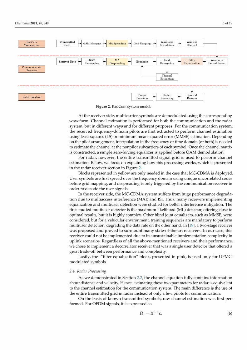
We consider a system model as depicted in Figure 2. A data source generates randombits, which are then modulated using QAM mapping. Afterwards, the QAM symbols arerearranged in a time–frequency grid. For communication purposes, Np pilots are insertedto be used in channel estimation at the communication receiver side. This grid is thenshaped in multicarrier symbols using either UFMC or OFDM waveform before passingthrough the wireless channel following the model given in (5).
Electronics 2021, 10, 849 5 of 19
Figure 2. RadCom system model.
At the receiver side, multicarrier symbols are demodulated using the correspondingwaveform. Channel estimation is performed for both the communication and the radarsystem, but in different ways and for different purposes. For the communication system,the received frequency-domain pilots are first extracted to perform channel estimationusing least-squares (LS) or minimum mean squared error (MMSE) estimation. Dependingon the pilot arrangement, interpolation in the frequency or time domain (or both) is neededto estimate the channel at the nonpilot subcarriers of each symbol. Once the channel matrixis constructed, a simple zero-forcing equalizer is applied before QAM demodulation.
For radar, however, the entire transmitted signal grid is used to perform channelestimation. Below, we focus on explaining how this processing works, which is presentedin the radar receiver section in Figure 2.
Blocks represented in yellow are only needed in the case that MC-CDMA is deployed.User symbols are first spread over the frequency domain using unique uncorrelated codesbefore grid mapping, and despreading is only triggered by the communication receiver inorder to decode the user signals.
In the receiver side, the MC-CDMA system suffers from huge performance degrada-tion due to multiaccess interference (MAI) and ISI. Thus, many receivers implementingequalization and multiuser detection were studied for better interference mitigation. Thefirst studied multiuser detector is the maximum likelihood (ML) detector, offering close tooptimal results, but it is highly complex. Other blind joint equalizers, such as MMSE, wereconsidered, but for a vehicular environment, training sequences are mandatory to performmultiuser detection, degrading the data rate on the other hand. In [19], a two-stage receiverwas proposed and proved to surmount many state-of-the-art receivers. In our case, thisreceiver could not be implemented due to its unsustainable implementation complexity inuplink scenarios. Regardless of all the above-mentioned receivers and their performance,we chose to implement a decorrelator receiver that was a single user detector that offered agreat trade-off between performance and complexity.
Lastly, the “filter equalization” block, presented in pink, is used only for UFMC-modulated symbols.
2.4. Radar Processing
As we demonstrated in Section 2.2, the channel equation fully contains informationabout distance and velocity. Hence, estimating these two parameters for radar is equivalentto the channel estimation for the communication system. The main difference is the use ofthe entire transmitted grid in radar instead of only a few pilots for communication.
On the basis of known transmitted symbols, raw channel estimation was first per-formed. For OFDM signals, it is expressed as
Ho = X−1Yo (6)

Electronics 2021, 10, 849 6 of 19
where Ho denotes the OFDM estimated channel, Yo the received signal, and X−1 is thetransmitted pilots for communication and the grid for radar. For UFMC, on the otherhand, raw channel estimation at each subcarrier can be written as
Hu = (FsXs)−1Yu, (7)
where Hu denotes the UFMC estimated channel, Yu the received signal, and (.)s meansthe subcarrier belonging to the s-th sub-band. Fs is the known filter frequency response atthis subcarrier. From Equations (6) and (7), it is clear that UFMC channel estimation onlydiffers from the OFDM one by the filter response. Hence, in the system model diagram(Figure 2), we propose to add a filter equalization block to account for the filter impact onthe UFMC-received signal. This operation afterwards makes the UFMC signal equivalentto OFDM. Hence, below, we drop the (.)u and (.)o subscripts.
This first step of channel estimation is simply a spectral division of the received signalby the transmitted one; hence, in the system model diagram, we present it by its name:spectral division. After spectral division (and filter equalization for UFMC), the estimatedfrequency-domain channel transfer function Hr,q at q-th subcarrier for the r-th symbol(ignoring the stretching and compression effects) can be given by
Hr,q =Lch−1
∑j=0
e−j2πq∆ f τj ej2π fdj
rNo
Nc∆ f + Zr,q, (8)
where ∆ f describes the subcarrier spacing, Zr,q denotes the additive white Gaussian noiseof the q-th subcarrier for the r-th symbol; No = Nc + Ncp is the OFDM symbol length, whereNc denotes Fast Fourier transform (FFT) length, and Ncp is CP length. Equation (8) showsthat the delay (hence, range) can be estimated using inverse FFT (IFFT) over the frequencyaxis. The Doppler shift (hence, velocity) can be evaluated using FFT over the time axis. Thisis equivalent to applying a 2D periodogram, as depicted in Figure 3. The main advantagein this approach is that the delay and Doppler estimations are independent. At first, thisoperation estimates frequency q and symbol r indices, which should then be translated todistance and velocity through the following equations:
dj = qjc
2N∆ f(9)
vj = rjc
2 fc MTo∆ f(10)
Figure 3. Two-dimensional (2D) periodogram processing.
N > Nc and M > Nsymb, where Nsymb denotes the total number of the transmittedsymbols, and N and M are the FFT and IFFT length of the 2D periodogram, respectively.To is the total duration of the OFDM symbol.

Electronics 2021, 10, 849 7 of 19
Deciding if a peak in the periodogram is a true target is basically a statistical detectionproblem that boils down to binary hypothetical testing. Hypotheses can be formulated asin Equation (11), where in H0, the received signal is noise, and in H1, the received signal isthe target-reflected one, propagating through the channel plus the noise.
y[n] =
{z[n] H0 noise onlyx[n] ⊗ h[n] + z[n] H1 signal plus noise
(11)
To decide between the two hypotheses, a test static ζ, which is a function of thereceived signal, is computed and compared to a threshold ξ, such that:
ζ<
H0
≥H1
ξ (12)
The result of the comparison of the test statistics with the threshold in Equation (12) isobtained from the probability density function (PDF) of the test statistic under H0 versusthe PDF under H1.
In radar processing, power detection is adopted. Hence, the threshold can be expressedas [20]:
ξ = σ2z ln(Pf a) (13)
where Pf a is false-alarm probability, and σ2z is noise power. More details are provided
in [20].
2.5. Waveform Parametrization
To allow for the proper parametrization of a RadCom waveform, the following criteriashould be respected for both communication and radar systems:
• Tcp > Td : where Td is the maximal expected delay spread to avoid ISI,
• fdmax∆ f � 1: to avoid ICI
• Tcp ∗ ∆ f � 1: to achieve spectral efficiency.
Subcarrier spacing is limited by the maximal Doppler shift, hence the speed of thetarget, while the cyclic prefix is limited by the delay, hence the target’s distance. These twoparameters add additional constraints for the radar. Maximal unambiguous distance isdetermined by subcarrier spacing ∆ f as follows:
dun =c
2∆ f, (14)
which also determines the distance resolution:
∆d =c
2Nc∆ f(15)
Nc∆ f is bandwidth. Furthermore, maximal unambiguous velocity is determined bythe symbol time (denoted Tmcm to account for both OFDM and UFMC):
vun =c
2 fcTmcm, (16)
which also determines the distance resolution:
∆v =c
2 fcNsymbTmcm(17)
NsymbTmcm is observation time.

Electronics 2021, 10, 849 8 of 19
3. OFDM RadCom Signal Model
The transmitted OFDM signal
xo[n] =M−1
∑r=0
Nc−1
∑q=0
aq,rej 2πq(n−rNo)Nc (18)
where No = Nc + Ncp is the OFDM symbol length. Ncp denotes the CP length needed toavoid ISIs. The received OFDM signal can be expressed as
yo[n] = xo[n] ⊗ h[n] + z[n], (19)
where z[n] denotes additive Gaussian noise with variance σ2z .
Using the propagation channel model as in (5), knowing that Ts =1
Nc∆ f , (19) becomes
yo[n] =M−1
∑r=0
Lch−1
∑j=0
Nc−1
∑q=0
hjaq,rej 2πqnNc e−j2πq∆ f τj
e−j2πqsjn
Nc e−j2πqrNo
Nc ej2π fdj
n
Nc∆ f + z[n]
The signal model for each OFDM symbol can be simplified to
yo[n, r] =Lch−1
∑j=0
Nc−1
∑q=0
hjaq,rej 2πqnNc e−j2πq∆ f τj
e−j2πqsjn
Nc e−j2πqrsj No
Nc ej2π fdj
n
Nc∆ f ej2π fdj
rNo
Nc∆ f + z[n]
1. Term ej 2πqnNc represents OFDM subcarriers and can be modeled as a DFT.
2. Second term e−j2πq∆ f τj represents the delay effect on the OFDM symbol. For thecommunication part, this effect is compensated for through equalization. In the radarpart, this term is used for range estimation.
3. Term ej2π fdj
n
Nc∆ f describes the Doppler shift that may lead to ICI.
4. Term ej2π fdj
rNo
Nc∆ f is the Doppler shift effect on each OFDM symbol. It is used for velocityestimation for radar.
4. UFMC RadCom Signal Model
The UFMC discrete-time baseband signal is the superposition of the sub-bandwisefiltered subcarriers [11]; therefore, it can be expressed as follows:
xu[n] =S−1
∑s=0
gs[n]⊗ xs[n] (20)
where ⊗ denotes linear convolution, and gs[n] is the filter used in the s-th sub-band. It isdefined in (21) as:
gs[n] = g[n]ej 2πQ/2nNc ej 2π(S0+sQ)n
Nc (21)
with g[n] being the prototype filter of length L, and S0 denoting the starting frequencyof the lowest sub-band. xs[n] is the s-th group of subcarriers, which is an OFDM symbolshifted to the appropriate sub-band. It is given by (22):
xs[n] =∞
∑r=−∞
Q−1
∑q=0
ss,q,rej2πq(n−rNu f mc)
Nc ej2π(S0+sQ)(n−rNu f mc)
Nc , (22)

Electronics 2021, 10, 849 9 of 19
where ss,q,r are complex symbols transmitted on the q-th subcarrier in the s-th sub-bandduring the r-th period. They are spread over the overall signal and transformed into the
time domain, with inverse discrete Fourier transform (IDFT) of length Nc. Term ej 2π(S0+sQ)nNc
performs frequency shifting of both data and filter coefficients to the appropriate sub-band. Because of convolution, the resulting UFMC signal is of length Nu f mc = Nc + L− 1.The filtering operation makes it possible to suppress the OOB leakages, with the Dolph–Chebyshev filter being the most common in the literature [11].
Replacing (21) and (22) in (20), and applying some simplifications, the transmittedUFMC signal can be written as in (23).
xu[n] =S−1
∑s=0
+∞
∑r=−∞
Q−1
∑q=0
L−1
∑l=0
ss,q,rgQ
[n− l − rNu f mc
]ej 2πql
Nc ej2π(S0+sQ)(n−rNu f mc)
Nc
with gQ[n] = g[n]ej 2πQ/2nNc being the prototype filter shifted to the sub-band center fre-
quency [11]. Considering the same channel model as for OFDM, the received UFMC signalcan be expressed as follows:
yu[n] = ej 2πnκNc
S−1
∑s=0
+∞
∑r=−∞
Q−1
∑q=0
Lch−1
∑j=0
L−1
∑l=0
ss,q,rh[ηj]e−j2π fdj
(n+δ)gQ
[n− l − ηj − rNu f mc + δ
]ej 2πql
Nc ej2π(S0+sQ)(n−ηj−rNu f mc+δ)
Nc (23)
Figure 4 depicts the synthesis of a UFMC signal.
Figure 4. Universal filtered multicarrier (UFMC) transmitter.
BER Analytical Model
In this subsection, we elaborate an analytical model of the BER. The analytical expres-sion of the M-ary QAM modulation over additive white Gaussian noise (AWGN) is givenby Equation (24).
BER =2(M− 1)M log2 M
Q
√6
γ log2(M)
M2 − 1
(24)
where M is the modulation order, γ denotes EbN0
, and Q is defined as the Q function:
Q(x) =1√2π
∫ +∞
xe−
t22 dt
BER calculation is easily performed using the following approximation of the Qfunction:
Q(x) ≈ 112
e−x22 +
16
e−2x2
3

Electronics 2021, 10, 849 10 of 19
Hence, for OFDM, the BER over each subcarrier can be deducted from the Equation (24).However, as subcarriers in the UFMC system are being filtered, noise variance on the qthsubcarrier of the sth sub-band is then divided by the equivalent filter response and can beexpressed as follows.
σ2q =
σ2z| fk|2
Thus, the BER expression of the qth subcarrier of the sth sub-band can be written as
BER(s, q) =2(M− 1)M log2 M
Q
√6| fk|2
γ log2(M)
M2 − 1
(25)
5. Simulation Results
In this section, some simulations and discussions are illustrated. We verify the pro-posed approach of UFMC and UFMC-CDMA RadCom systems and compare it with thatof an OFDM RadCom system. First, the performance of the radar system is examined andcompared with that of OFDM. Afterwards, UFMC and UFMC-CDMA communicationsystems are evaluated over different channels and compared with OFDM. Spreading se-quences and filter-length simulations are provided for both radar and communication tofind how they either degrade or enhance overall performances. All simulated scenarioswere performed in MATLAB.
5.1. Radar-System Performance Evaluation
Table 1 summarizes the simulation parameters that were chosen according to thedesign criteria presented previously in Section 2.5.
Table 1. Simulation parameters. IDFT, inverse discrete Fourier transform; CP, cyclic prefix; QAM,quadrature amplitude modulation.
Parameter Symbol Value
Overall parameters
Subcarrier spacing ∆ f 120 kHzSampling time Ts
1∆ f ∗Nc
Carrier frequency fc 77 GHzIDFT size Nc 2048Symbols Nsymb 175
Slots Nslot 25Symbols per slot NSpS 7
CP length Ncp 328QAM - 4-QAM
Radar parameters
Maximum range dmax 200 mRange resolution ∆d 0.6 m
Velocity resolution ∆v 1.34 m/sProbability of false alarm Pf a 1× 10⁻²
Signal-to-noise ratio SNR 10 dB
UFMC
Filter type - Dolph–ChebyshevFilter attenuation - 50 dB
Targets
Distance (m) di [55;55;60;80]Velocity (m/s) vi [35;37;30;20]

Electronics 2021, 10, 849 11 of 19
For targets, we chose to simulate 4 targets in which 2 targets shared the same distanceand very close velocity to verify velocity resolution. Target 1 at a distance d = 55 m withvelocity v = 35 m/s, Target 2 with d = 55 m and v = 37 m/s, Target 3 at a distanced = 60 m distance d = 60 m and v = 30 m/s, and Target 4 with d = 80 m and v = 20 m/s.The UFMC parameters adopted in this case were sub-band size Q = 64 and filter lengthwas 16 for optimal performance.
In a vehicular context, relevant maximal target distance does not exceed d = 200 m.Considering the sampling time of the signals, receivers can efficiently mitigate the effect ofISI, when maximal delay is within the CP duration for OFDM. For UFMC, on the otherhand, the filter ramp-up and -down at the edges of the symbol guarantees soft protectionagainst ISI. The energy contained in the L last samples of the UFMC signal is relativelysmall. However, the choice of filter length also impacts the correct estimation of targetdistance and velocity, since energy is not equal among all subcarriers.
Figure 5 depicts the periodogram of the two received signals computed using theparameters in Table 1. Results confirmed that both suggested waveforms are suitable forradar, as we can clearly see the four targets on the distance–velocity grid. Furthermore,the UFMC waveform reduces the high OOB power emission while retaining the simplicityof the conventional OFDM signal. This also offers increased spectral efficiency due to theomission of CP.
(a)
(b)
Figure 5. UFMC waveform vs orthogonal frequency division multiplexing (OFDM) waveform: (a)UFMC. (b) OFDM.

Electronics 2021, 10, 849 12 of 19
While UFMC proved to be suitable for radar application as a new 5G waveform,we suggest to implement MA techniques, more specifically CDMA, to study how thespreading can affect obstacle detection. The spreading sequences that we chose in oursimulation are the Walsh–Hadamard sequences because of their ease of implementation,high autocorrelation, and low cross-correlation properties. The order of the used sequencesis Nc, and the evaluation of radar performance is performed with different scramblingpatterns. The nature of the spreading sequences used by the transmitter changed theoutcome of the simulation.
As depicted in Figure 6, we chose three Walsh–Hadamard codes with the samelength, categorized as follows: a nonscrambled sequence, which is a sequence of ones, andusually the first generated sequence in the Hadamard matrix; the second code is morescrambled compared to the first and sequels 64 chips of the same binary codeword; the lastsequence is the most scrambled sequence that could be generated. By choosing these threeconfigurations, we implemented both worst- and best-case scenarios, and a third case toback up the overall results.
0 20 40 60 80 100 120
-2
0
2
Non-scrambled Code
0 20 40 60 80 100 120
-2
0
2
Low-scrambled Code
0 20 40 60 80 100 120
-2
0
2
High-scrambled Code
Figure 6. Walsh-Hadamard spreading. codes representation.
In order to illustrate the difference between the three codes, Figure 7 depicts theperiodogram of UFMC-CDMA. The nonscrambled sequence yielded severe deteriorationto the received signal compared to the other sequences, while the high-scrambled sequencepresented optimal results. Interferences induced to the transmitted signal by its own echosin this multipath environment decreased the probability of detection due to constant energyspreading. Consequently, in order to minimize interference resulting from the presence ofmultiple copies of the spread signal, the use of a scrambled signature sequence divides thesignal energy differently over all subcarriers, optimizing radar-system performance.

Electronics 2021, 10, 849 13 of 19
(a)
(b)
(c)
Figure 7. UFMC-code division multiple access (CDMA) radar performance with different spreadingcodes: (a) nonscrambled, (b) low-scrambled, and (c) high-scrambled codes.

Electronics 2021, 10, 849 14 of 19
5.2. Communication-System Performance Evaluation
In this subsection, we compare the performance of the communication system of theUFMC scheme with OFDM over a multipath vehicular channel with different Dopplerfrequencies, in particular, the tapped delay line A (TDL-A) channel. The TDL-A channelmodel has a Doppler spectrum that is characterized by Jake’s spectrum shape. The powerdelay profile (PDP) of the model is presented in [21], and the delay spread used to scale thenormalised tap delays was Ds = 26 ns. This delay spread was chosen to correspond toa short delay profile in a UMi Street-canyon for a 70 GHz carrier frequency to match thecarrier frequency of our RadCom system.
Seven-symbol slots were considered in the transmission system, and pilot-aidedchannel estimation was used in our simulations. We chose to insert pilot symbols in thegrid according to two different configurations. In the frequency domain, the positions ofthe pilots were determined by pilot spacing. In our case, we fixed the pilot spacing to4; hence, 512 resource elements (RE) were allocated for pilots. For the time domain, wechose a low-density configuration where only the first symbol was allocated for pilots, andhigh-density configuration where the first and the fifth symbols were allocated for pilotsymbols. For complexity and enhancement considerations, it is more interesting to use theMMSE channel estimator and ZF equalizer.
While communicating, the system parameters are updated for optimization reasons.First, subcarrier spacing is reduced to 15 KHz for optimal spectral efficiency; hence, sam-pling frequency is also reduced. Moreover, the total number of transmitted symbols isno longer fixed at 175 symbols and becomes flexible depending on the requirementsof the transmitter. No error-correction coding was deployed. For UFMC-CDMA, weadded multiuser interference (MUI) with 3 different patterns, where 5, 6, and 7 users weresuperimposed at each subcarrier for each pattern, respectively.
As presented in Figure 8, the high-density configuration slightly outperformed thelow-density configuration; however, the overall performance of both OFDM and UFMCwaveforms was highly degraded due to the high delays induced by the TDL-A channel.Comparing the previous figures shows that the gap between the pilot configurations ismore significant over a higher maximal Doppler shift i.e., a higher speed. This is due to thetime-domain enhancement of the pilot insertion. With regard to waveform comparison,UFMC and OFDM exhibited the same BER performance, while UFMC offered the greatadvantage of OOB reduction and increased the overall spectral efficiency.
Regarding UFMC-CDMA, the TDL-A channel delays and patterns of interferencebetween served users directly impacted the BER. System performance degraded as the num-ber of users became larger, as shown in Figure 9. However, even for the long delays inducedby channel and filter selectivity, UFMC-CDMA showed improved overall performance.
5.3. Filter-Length Analysis
The last stage of our simulations was filter-length analysis, where we defined the filterlength that is suitable for the RadCom application. We mainly fixed the SNR to 10 dBand performed both detection and communication to observe how filter length can eitherimprove or worsen the performance of the UFMC RadCom system.
The frequency selectivity of the filter is is what makes UFMC signal well-localized inthe frequency domain and reduces OOB emissions. However, filter-frequency selectivitymay cause system performance loss, as Figure 10 shows. When filter length increases,selectivity among subcarriers increases. On the basis of these results, we recommend thatfilter length should be chosen to be proportional to the number of subcarriers divided bysub-band size Nc
Q .
L ∝Nc
Q(26)

Electronics 2021, 10, 849 15 of 19
(a)0 2 4 6 8 10 12 14 16 18 20
SNR
10-3
10-2
10-1
100
BE
R
TDL-A
Low Density UFMC
Low Density OFDM
High Density UFMC
High Density OFDM
UFMC Single User Bound
(b)
0 2 4 6 8 10 12 14 16 18 20
SNR
10-3
10-2
10-1
100
BE
R
TDL-A
Low Density UFMC
Low Density OFDM
High Density UFMC
High Density OFDM
UFMC Single User Bound
Figure 8. Uncoded bit error rate (BER) of UFMC vs OFDM under tapped delay line A (TDL-A)channel and maximal Doppler Shift: (a) maximal Doppler shift fd = 10 Hz; (b) maximal DopplerShift fd = 100 Hz.

Electronics 2021, 10, 849 16 of 19
0 2 4 6 8 10 12 14 16 18
SNR
10-6
10-5
10-4
10-3
10-2
10-1
100
BE
R
TDL-A
UFMC-CDMA 5 users
UFMC-CDMA 6 users
UFMC-CDMA 7 users
Figure 9. Uncoded BER of UFMC-CDMA under TDL-A channel and maximal Doppler shift fd = 100 Hz.
(a)
(b)
Figure 10. UFMC with fixed sub-band size Q and different filter length L: (a) Q = 128 and L = 16.(b) Q = 128 and L = 70.

Electronics 2021, 10, 849 17 of 19
Figure 10 also shows that UFMC-CDMA, even with a high-scrambled signaturesequence, suffered from the same deterioration as that caused by filter-frequency selectivity.
Regarding the communication aspect of the RadCom UFMC system, we evaluatedfilter length only over an AWGN channel and with different sub-band sizes for a better com-parison.
The BER versus filter-length curves for different sub-band sizes are presented inFigure 11. By increasing sub-band size and filter length, overall performance was degraded.For the case of Q = 16, the BER was at 10−3 dB for a filter length that ranged from 2 to 128.However, for Q = 128, the BER began to rapidly degrade as soon as the filter length reachedL = 16. For other sub-band cases, degradation was close to L = Nc
Q . Hence, optimal filter-
length configuration L should be chosen to be smaller than NcQ for optimal performance.
20 40 60 80 100 120
Filter Length
10-4
10-3
10-2
10-1
100
BE
R
Filter Length Evaluation
Q=16
Q=32
Q=64
Q=128
Figure 11. Filter length evaluation over AWGN channel.
6. Conclusions
In this paper, UFMC, as a new 5G waveform, and UFMC-CDMA were proposedas a RadCom system, and they proved to be suitable for this application by means ofsimulations while offering great radar and communication performance. First, the OFDMand UFMC waveform parametrization and the UFMC-CDMA signal model details weredescribed. An analytical model of the UFMC BER was also provided. On the basis ofRadCom system requirements, multiaccess techniques can be implemented to support aV2X multiuser environment; consequently, simulations were performed with and with-out multiaccess. The UFMC waveform is capable of supporting a RadCom system withaffordable complexity, similar to OFDM, while offering optimal spectral efficiency. In addi-tion, filter length was investigated, and filter length should be chosen to be smaller than Nc
Qfor communication, Regarding radar requirements, it should be chosen to be proportionalto Nc
Q . As for UFMC-CDMA, it was proven that the choice of spreading sequence can affectthe overall performance of the radar. The more scrambled the sequence is, the more optimalresults are. Furthermore, filter-frequency selectivity affected UFMC-CDMA performance.The performed simulations did not hold any error-correction coding; thus, added errorcorrection coding would enhance system performance.

Electronics 2021, 10, 849 18 of 19
Author Contributions: conceptualisation, I.K., K.Z., R.E., F.E., and N.I.; methodology, I.K., K.Z.,R.E., and F.E.; software, I.K. and K.Z.; validation, R.E., F.E., and N.I.; formal analysis, R.E. and F.E.;investigation, I.K., K.Z., R.E., and F.E.; resources, R.E. and F.E.; writing—original-draft preparation,I.K. and K.Z.; writing—review and editing, I.K. K.Z., R.E., and F.E.; supervision, R.E., F.E., and N.I.;project administration, R.E. and F.E.; funding acquisition, R.E. and F.E. All authors have read andagreed to the published version of the manuscript.
Funding: The present research work was supported by the European project SECREDAS funded ECSEL.
Data Availability Statement: The data presented in this study are available on request from thecorresponding author.
Conflicts of Interest: The authors declare no conflict of interest.
AbbreviationsThe following abbreviations are used in this manuscript:
OFDM Orthogonal frequency division multiplexingUFMC Universal filtered multicarrierBER Bit error rateMA Multiple accessITU International telecommunication unionCP Cyclic prefixICI Intercarrier interferenceISI Intersymbol interferenceOOB Out of bandQAM Quadrature Amplitude ModulationMC-CDMA Multicarrier code division multiple accessCDMA Code division multiple accessTDM Time division multiplexingBS Base stationIFFT Inverse fast Fourier transformLS Least squaresFFT Fast Fourier transformMMSE Minimum mean squared errorZF Zero forcingPDF Probability density functionIDFT Inverse discrete Fourier transformSNR Signal-to-noise ratioAWGN Additive white Gaussian noiseTDL-A Tapped delay line APDP Power delay profileRE Resource elementMUI Multiuser interferenceMAI Multiaccess interference
References1. Systems Characteristics of Automotive Radars Operating in the Frequency Band 76–81 GHz for Intelligent Transport Systems
Applications. Itu-r m.2057-1, ITU. 2018. Available online: https://www.itu.int/rec/R-REC-M.2057/en (accessed on 15 August2019).
2. Fink, J.; Jondral, F.K. Comparison of OFDM radar and chirp sequence radar. In Proceedings of the 2015 16th International RadarSymposium (IRS), Dresden, Germany, 24–26 June 2015; pp. 315–320. [CrossRef]
3. Levanon, N. Multifrequency radar signals. In Proceedings of the Record of the IEEE 2000 International Radar Conference,Alexandria, VA, USA, 12–12 May 2000; pp. 683–688.
4. Levanon, N. Multifrequency Signal Structure for Radar Systems. U.S. Patent 6,392,588, 21 May 2002.5. Donnet, B.; Longstaff, I. Combining MIMO radar with OFDM communications. In Proceedings of the European Radar Conference
2006, Manchester, UK, 13–15 September 2006; pp. 37–40.6. Lellouch, G.; Tran, P.; Pribic, R.; Van Genderen, P. OFDM waveforms for frequency agility and opportunities for Doppler
processing in radar. In Proceedings of the 2008 IEEE Radar Conference, Rome, Italy, 26–30 May 2008; pp. 1–6.
Electronics 2021, 10, 849 19 of 19
7. Sturm, C.; Wiesbeck, W. Waveform design and signal processing aspects for fusion of wireless communications and radar sensing.Proc. IEEE 2011, 99, 1236–1259. [CrossRef]
8. Vakilian, V.; Wild, T.; Schaich, F.; ten Brink, S.; Frigon, J.F. Universal-filtered multi-carrier technique for wireless systems beyondLTE. In Proceedings of the IEEE Globecom Workshops (GC Wkshps), Atlanta, GA, USA, 9–13 December 2013; pp. 223–228.
9. Zhang, L.; Ijaz, A.; Xiao, P.; ul Quddus, A.; Tafazolli, R. Subband Filtered Multi-Carrier Systems for Multi-Service WirelessCommunications. IEEE Trans. Wirel. Commun. 2017, 16, 1893–1907. [CrossRef]
10. Khelouani, I.; Elbahhar, F.; Elassali, R.; Idboufker, N. Performance Analysis of LDS Multi Access Technique and New 5GWaveforms for V2X Communication. Electronics 2020, 9, 1094. [CrossRef]
11. Matthe, M.; Zhang, D.; Schaich, F.; Wild, T.; Ahmed, R.; Fettweis, G. A Reduced Complexity Time-Domain Transmitter forUF-OFDM. In Proceedings of the 2016 IEEE 83rd Vehicular Technology Conference (VTC Spring), Nanjing, China, 15–18 May2016; pp. 1–5.
12. Final 5GNOW Transceiver and Frame Structure Concept; Available online: https://is-wireless.com/wp-content/uploads/2015/11/5GNOW_Deliverables-Final-5GNOW-Transceiver-and-frame-structure-concept.pdf (accessed on 4 May 2015).
13. Munshi, A.; Unnikrishnan, S. Vehicle to Vehicle Communication Using DS-CDMA Radar. Procedia Comput. Sci. 2015, 49, 235–243.[CrossRef]
14. Shaojian, X.; Bing, C.; Ping, Z. Radar-Communication Integration Based on DSSS Techniques. In Proceedings of the 2006 8thinternational Conference on Signal Processing, Guilin, China, 16–20 November 2006; Volume 4. [CrossRef]
15. Hara, S.; Prasad, R. Design and performance of multicarrier CDMA system in frequency-selective Rayleigh fading channels.IEEE Trans. Veh. Technol. 1999, 48, 1584–1595. [CrossRef]
16. Napolitano, A. Cyclostationarity: Limits and generalizations. Signal Process. 2016, 120, 323–347. [CrossRef]17. Cho, Y.S.; Kim, J.; Yang, W.Y.; Kang, C.G. MIMO-OFDM Wireless Communications with MATLAB; John Wiley and Sons: Hoboken,
NJ, USA, 2010.18. Napolitano, A. Generalizations of Cyclostationary Signal Processing: Spectral Analysis and Applications; John Wiley and Sons: Hoboken,
NJ, USA, 2012; Volume 95.19. Gelli, G.; Paura, L.; Verde, F. A two-stage CMA-based receiver for blind joint equalization and multiuser detection in high
data-rate DS-CDMA systems. IEEE Trans. Wirel. Commun. 2004, 3, 1209–1223. [CrossRef]20. Braun, M. OFDM Radar Algorithms in Mobile Communication Networks. Ph.D. Thesis, KIT-Bibliothek, Karlsruhe, Germany,
2014.21. Study on Channel Model for Frequencies from 0.5 to 100 GHz. Tr 38.901, 3GPP. 2017. Available online: https://www.etsi.org/
deliver/etsi_tr/138900_138999/138901/14.00.00_60/tr_138901v140000p.pdf (accessed on 1 January 2021).