ufc 4-25-01 security engineering: waterfront security · 1 waterfront security aug 2017 ufc 4-25-01...
TRANSCRIPT

1 Waterfront Security Aug 2017
UFC 4-25-01 Security Engineering: Waterfront Security
NAVFAC Northwest Presented by: Richard Cofer, P.E.
Naval Facilities Engineering Command Atlantic Capital Improvements Business LineEngineering Criteria and Programs
Aug 2017
3 Waterfront Security Aug 2017
UFC 4-025-01, SECURITY ENGINNEERING: WATERFRONT SECURITY
• Purpose:– Present a unified approach for AT and
physical security systems that protect waterfront assets.
• Applicability:– Applies to all construction, renovation, and
repair projects including expeditionary or temporary construction of waterfront facilities onboard DoD installations. This document does not apply to ports of call.
• Lead Agency: NAVFAC– Point of contact: Richard Cofer
• Current Document Status:– Published November 2012
4 Waterfront Security Aug 2017
Policy Based Requirements
• The requirement to protect waterfront assets comes from DoD Instruction/Directives, Geographic Combatant Commander (GCC) Instructions, Service Instruction/Directives, and Regional or Installation requirements.
• Department of Defense – DOD 5200.8-R: Requires DOD Components to determine the necessary access
control based on the requirements of a developed physical security program. Establishes procedures and responsibilities for security of weapon systems, including platforms, such as armored fighting vehicles, fixed- and rotary-wing aircraft, and ships in port.
– DODD 2000.12: Provides DOD policies for ATFP and assigns responsibilities for implementing the procedures for the DOD ATFP Program
– DODI 2000.16: This instruction requires the installation or activity Commanding Officer to define the access control measures at installations.
– Directive-Type Memorandum (DTM) 09-012: Establishes DoD access control policy and the minimum DoD security standards for controlling entry to DoD installations and stand-alone facilities

5 Waterfront Security Aug 2017
Policy Based Requirements
• Geographic Combatant Commander (GCC) Requirements– GCC issue requirements for Antiterrorism and physical security for
installations within their area of responsibility. Ensure any such requirements are incorporated in addition to the requirements found in DoD and Service Directive/Instructions.
– Resolve any differences in the requirements for the design of a waterfront security by applying the most stringent requirement.
• Department of the Navy– OPNAVINST 5530.14E: Provides the requirements for installation and
restricted area access control. Provides Waterside and Waterfront security requirements and waterway access control.
– NTTP 3-07.2.3: Provides guidance for the physical security for Naval Installations to include Restricted Areas and Waterfront Security.
6 Waterfront Security Aug 2017
Policy Based Requirements
• Installation Specific Requirements– As required by DODI 2000.16 and service directives, each installation
must have an Antiterrorism Plan.
• The plan provides procedures and recommendations for reducing risk and vulnerability of DOD personnel, their family members, facilities, and assets from acts of terrorism.
– As required by OPNAVINST 5530.14E Installation Commanding Officers shall ensure that Physical Security surveys of their activities are conducted annually and the results addressed as a part of a command review and assessment program.
• Surveys will serve to update the command on what needs protecting, what security measures are in effect, what needs improvement, and what the security priorities are.
• The installation AT plan and Physical Security survey reflects the foundation for requirements determination. Installation specific requirements need to be factored into all capital improvement initiatives.

7 Waterfront Security Aug 2017
Definitions
• Design basis threat (DBT) – The threat against which an asset must be protected and upon which
the protective system's design is based. It is the baseline type and size of threat that buildings or other structures are designed to withstand. The DBT includes the tactics aggressors will use against the asset and the tools, weapons, and explosives employed in these tactics.
• Level of protection– The degree to which an asset is protected against compromise
• Landside– The land within the controlled or restricted area adjacent to the body
of water. This includes facilities such as wharves or similar structures and includes the adjacent, facilities, parking and roadways
• Restricted Area– An area under military jurisdiction in which special security measures
are employed to prevent unauthorized entry.
8 Waterfront Security Aug 2017
Definitions
• Waterfront– The area of the DoD installation adjacent to a body of water. This area
comprises waterfront assets and the surrounding area including the adjacent waterway, land, facilities, parking, and roadways.
• Waterfront Assets– Waterfront assets are vessels, personnel, and facilities such as piers, wharves,
docks or similar structures used to berth vessels
• Waterfront Security System– Waterfront security system is that subset of an Installation’s physical security
system specifically designed to safeguard waterfront assets against espionage, sabotage, damage, or theft.
• Waterside Security. – Measures or actions taken to prevent or guard against the use of a waterside
approach to a waterfront facility or vessel by persons or vessels intent on theft, sabotage, terrorism, and/or belligerent acts
• Waterside– The body of water (waterway) adjacent to the DoD installation that is monitored
and or controlled by the Installation. The waterside includes the piers and similar structures built out into the water.

9 Waterfront Security Aug 2017
WATERFRONT
10 Waterfront Security Aug 2017
Considerations
•The objective of waterfront security system is to secure the waterfront from unauthorized access and to detect and neutralize threats while minimizing impacts to port operations and the environment. Design considerations are:
– Security
– Port Operations
– Safety
– Appearance
– Environmental impact

11 Waterfront Security Aug 2017
Considerations
• Security– Installations should focus first on threats at the first line of defense –
the installation perimeter.
– The first priority of a waterside security system is to establish and maintain perimeter security.
– The waterfront:• Is a part of the installation perimeter and a legal line of demarcation
• Must be able to accommodate Random Antiterrorism Measures (RAMS) employment for sustained operations in order to validate installation’s ability to affect directed security posture.
• Must be able to operate at all FPCONs; and must have security features that protect against landside and waterside threats and unauthorized entry
• Port Operations– Design the waterfront security systems to maximize security while
minimizing the impact on port operations. Ships must be able to sortie effectively without compromising safety, security, or causing undue delays that may affect port or fleet operations.
12 Waterfront Security Aug 2017
Considerations
• Safety– Waterfronts must have a working environment that is both safe and
effective for security forces and personnel working in the waterfront area. Safety includes provisions for personal protection against attack and mishaps.
• Appearance– Design waterfront security systems to impart an immediate impression
of professionalism and convey the DOD’s commitment to the security of DOD personnel and its mission critical assets, facilities, and resources.
• Environmental Impact– Design waterfront security systems to minimize environmental impact
on the adjacent waterway. Include environmental representatives in the initial planning, design and construction of applicable projects to ensure there are no compliance issues, and that all regulatory approvals are received in a timely manner.

13 Waterfront Security Aug 2017
Detect, Delay, and Respond
• A physical security system must operate on the principle of Detect, Delay, and Respond. To be effective, the time between detection of an intrusion and response by security forces must be less than the time it takes to damage or compromise the protected asset.
– Detect• Detection and assessment of the potential threats may be accomplished through
ESS, electronic harbor security system (EHSS), security lighting, security forces, DoD personnel, military working dogs. Training and operational procedures are critical to detection and assessment as they improve personnel capabilities and support application of consistent concepts and practices.
– Delay• Delay is the time it takes for the aggressor to get from the point of detection to
compromising the protected asset. The time delay that a physical security system provides is critical to asset security. The time delay of the system must be synchronized with security force response time to ensure that maximum security is afforded to critical assets.
– Response• Response is the time it takes for the response capability to interrupt or neutralize a
threat. This includes communication, mobilization, travel time, and tactics
14 Waterfront Security Aug 2017
Physical Security Systems
• To create an effective system, the time between detection and response by response capability must be less than the time it takes the threat to compromise the asset.
– This is accomplished by detecting threats at the farthest possible distance from the asset and providing delays between the detection points and the asset giving the response capability time neutralize threat.
• This presents a challenge on the waterside due to limited distances between waterfront assets and unrestricted waterways.

15 Waterfront Security Aug 2017
WATERFRONT PHYSICAL SECURITY FUNCTIONS
16 Waterfront Security Aug 2017
WATERFRONT SECURITY ELEMENTS
WATERSIDE LANDSIDE
WATER PIERS/ WHARFS LANDChannel MarkersBuoy lineBarriersSignagePatrol BoatsElectronic Harbor Security System (EHSS) Surface
detection/assessmento Cameraso Thermal Imagerso Radaro Video Analytics
Subsurface detection/assessmento Sonar
Guard TowersSecurity LightingAccess Control Point Vehicle Pedestrian
Giant Voice
FencesAccess Control Point Vehicle Pedestrian
Security LightingElectronic Security System (ESS) Camera Intrusion Detection Access Control
Giant Voice

17 Waterfront Security Aug 2017
System Effectiveness
• A well designed physical security system will:– Provide defense-in-depth
– Provide continuous protection
– Enhance detect, delay, and response function
• Effective waterfront security systems must be compatible with the installation’s operational and security procedures.
– Measures that are excessive, inappropriate may eventually be eliminated or bypassed.
– Poorly placed fencing or barriers can reroute cranes, forklifts or container carriers to pavement areas not designed for heavy loads.
– Forklift tines and crane hooks can damage security equipment rendering the system inoperable.
• Minimize impediments to waterfront operations and security hardware by placement and consolidation.
18 Waterfront Security Aug 2017
Establish Requirements
• Establish an interdisciplinary planning team with local considerations to include the following:
– Supported Command
– Security forces
– Port Operations
– Installation/Regional Anti-terrorism Officer (ATO)
– Communications Officers
– Safety Officers
– Engineering
– Environmental
– Planning
– Local, state, Federal, or host nation officials to ensure integrity of restrictive access to the installation and reduce the potential adverse effects on surrounding communities.
• For some waterfront assets, the minimum security measures are established by policy or regulation.

19 Waterfront Security Aug 2017
Establish Requirements
• Future Development Plans– Evaluate future development plans for the installation and the
surrounding community.
– All waterfront security development plans should accommodate future modifications necessitated by increased demand, additional assets, additional facilities, or revised security measures.
• Document Requirements– Document the planning requirements for endorsement by the
Installation ATO and Port Ops Officers to ensure protective measures support the installation’s physical security system, AT plan, and waterfront operations.
20 Waterfront Security Aug 2017
Key Inputs

21 Waterfront Security Aug 2017
TABLE 2-3: SECURITY OF WATERFRONT ASSETS MATRIX IN U.S. NAVY CONTROLLED PORTS
Priority AssetSecurity Measures
(Accumulative from low to high)
A(Highest)
SSBN Per SECNAVINST S8126.1 and at non-home ports (Highest) where cumulative asset in port time exceeds more than 120 days in a calendar year, use water barriers to stop small boat threat.
B(High)
Carriers, other submarines, and large-deck amphibious
Electronic water/waterside security system (closed-circuit television, associated alarms, surface craft or swimmer detection, underwater detection) .
Use water barrier(s) to prevent direct unchallenged access from small boat attacks.
Submarines and aircraft carriers shall receive an armed escort during ingress and egress.
C(Medium)
Surface combatants, other auxiliary, MSCSSS, ammunitionships, mineWarfare
Establish security zone with the USCG, where possible. Use water barrier{s) where appropriate amphibious, and/or
practical, harbor patrol boat (s) with bullhorn, night vision device, spotlight, marine flares, and lethal and non-lethal weapons.
Arrange patrol boat backup support from harbor operations, USCG, or other (tenant boat units, small craft from ships) .
D(Low)
Patrol coastal MSC SSS (reduced Operational status) , pier facilities
Adjacent landside security (patrols, surveillance, pier access control) , no special requirement in waterways
Identify restricted area waterway(s) with buoys and signs.
22 Waterfront Security Aug 2017
Key Inputs
• Design Basis Threat (DBT)– The DBT links aggressor with tactic.
– It includes the aggressor tactics and the associated weapons such as explosives, tools, and agents.
– The DBT must be determined to plan and design the protective measures required to protect the assets from compromise.
• Waterfront should have a DBT for the landside and waterside. For example :
– Landside: placed or stationary vehicle bomb consisting of Type II explosive.
– Waterside: 2,000 lb. (907 kg) powerboat containing a Type I explosive.

23 Waterfront Security Aug 2017
Design Strategy
• All protective measures must support the concept of detect, delay and respond and facilitate security force’s ability to determine capability, opportunity, and intent of would be aggressors.
• When possible, physical security systems shall use a defense-in-depth approach, which effectively employs human and other physical security measures throughout the installation to create a layered defense against potential threats
–Defense-in-depth insures that no single point of failure would render assets vulnerable to compromise.
–This strategy utilizes a zone concept that establishes areas within the installation and their associated security measures.
24 Waterfront Security Aug 2017
Design Strategy
• Zone Concept–Public Area
• Area outside an installation or controlled perimeter where the public has unrestricted access.
–Access Control Area• The installation’s entry control points where authorized personnel transition from public zone to the DoD installation.
–Controlled Area• The area within the installation’s controlled perimeter where authorized personnel have access. Installations are considered controlled areas for the purposes of national defense.
–Restricted Area• A defined area established to protect critical assets by providing a higher level of security than that afforded elsewhere on the installation.

25 Waterfront Security Aug 2017
Design Strategy
• An installation must establish clearly defined sequence of boundaries through which personnel must pass to reach the restricted area.
– Security measures and access controls must increase as personnel transition from lower to higher security areas.
26 Waterfront Security Aug 2017
Design Strategy
• Establish Perimeter– To protect waterfront assets from unauthorized access, it is important
to establish and maintain a defined perimeter.
– Before a person proceeds into the waterfront restricted area, they must perceive the area boundary and understand the consequences associated with crossing it.
– The use of ESS on the landside and EHSS on the waterside enhance:• Detection of unauthorized access with an intrusion detection system (IDS)
• Improve the validation of credentials with access control systems (ACS)
• Threat detection, alarm assessment, surveillance, and archiving with video imaging.
The easiest and least costly opportunity for achieving the appropriate levels of protection against terrorist threats is to incorporate sufficient standoff distance to mitigate the defined threat.

27 Waterfront Security Aug 2017
Design Strategy
• Landside Perimeter– The landside perimeter of the enclave may consist of fences, walls,
signage, natural barriers, and ACPs for authorized vehicles and pedestrians. In addition, a final denial boundary may be established at the foot of a pier creating defense-in-depth. See chapter 4 for Landside protection measures.
• Waterside Perimeter– The waterside boundary of the enclave may consist of channel
markers, buoys, float lines, signage, or boat barriers.
– The transition from the public area to the restricted area may not go through additional areas or zones. Therefore, the boundary on the waterside may have to provide a higher LOP (delay) for critical assets than the landside counterparts to ensure critical assets are not compromised.
28 Waterfront Security Aug 2017
Design Strategy
• Signage– Access Control Point (ACP) Signage.
• Post reflective signs at all waterfront vehicle and pedestrian ACPs
– Restricted area signage.• Post reflective signs at intervals no greater than 100 feet (30.5 m) along the
entire perimeter of the restricted area and where boundaries make abrupt changes in direction. For example see Figure 3-3.
– Boat Barrier Signage.• Post reflective signs at intervals no greater than 100 feet (30.5 m) along the
entire boat barrier perimeter and on moorings.

29 Waterfront Security Aug 2017
LANDSIDE
• GENERAL DESIGN STRATEGY– The general design strategy for the landside is to establish and
maintain defense in depth through the application of standoff, barriers, access control, operational procedures, and security zones
– Establish multiple perimeters, boundaries, or zones through which unauthorized personnel must pass to access protected assets.
– Security Zones• Controlled Area
– The area within the installation’s controlled perimeter where authorized personnel have access
• Waterfront Restricted Area (enclave): – A defined waterfront area in which there are special measures employed to prevent
unauthorized entry. Restricted areas may be of different types depending on the nature and varying degree of importance of the protected asset and may extend beyond the piers or wharfs to the surrounding areas. Restricted areas must be authorized by the installation commander, properly posted, and employ physical security measures.
• Asset location: – The area where the protected asset is located. For vessels, this would be a pier, wharf
or dry dock.
30 Waterfront Security Aug 2017
LANDSIDE: Security Zones

31 Waterfront Security Aug 2017
LANDSIDE ACCESS CONTROL
• Design of the access control system begins at the Installation’s perimeter and access control points.
• Vehicles and personnel travel from one zone to another through the system to reach the restricted area.
• Physical security measures, including access control must increase from lower to higher security areas.
• The pier or wharf where critical assets are berthed are considered the final denial and should have the highest access control measures in the system
32 Waterfront Security Aug 2017
LANDSIDE: Access Control Layers
• LAYER I: INSTALLATION PERIMETER– The Installation’s controlled perimeter, access control points, and the
related security procedures must be considered when determining the design basis threat and the resulting protective measures for the waterfront.
33 Waterfront Security Aug 2017
LANDSIDE: Access Control Layers
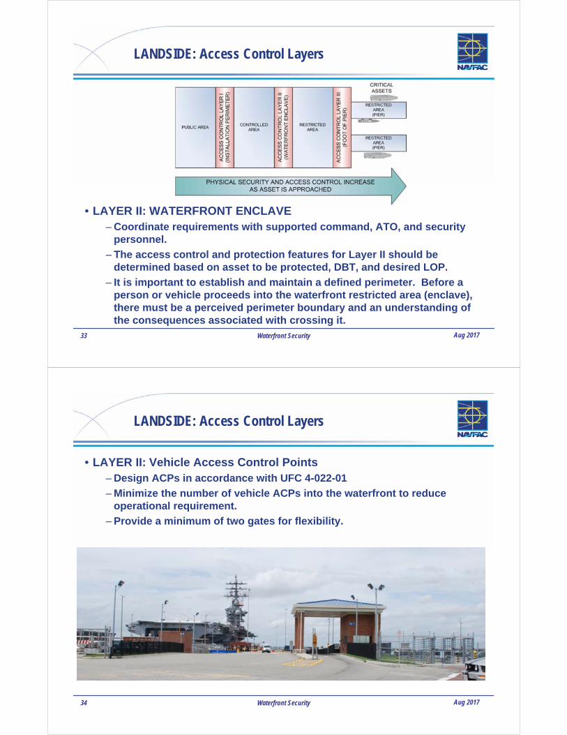
• LAYER II: WATERFRONT ENCLAVE– Coordinate requirements with supported command, ATO, and security
personnel.
– The access control and protection features for Layer II should be determined based on asset to be protected, DBT, and desired LOP.
– It is important to establish and maintain a defined perimeter. Before a person or vehicle proceeds into the waterfront restricted area (enclave), there must be a perceived perimeter boundary and an understanding of the consequences associated with crossing it.
34 Waterfront Security Aug 2017
LANDSIDE: Access Control Layers
• LAYER II: Vehicle Access Control Points– Design ACPs in accordance with UFC 4-022-01
– Minimize the number of vehicle ACPs into the waterfront to reduce operational requirement.
– Provide a minimum of two gates for flexibility.
35 Waterfront Security Aug 2017
LANDSIDE: Access Control Layers
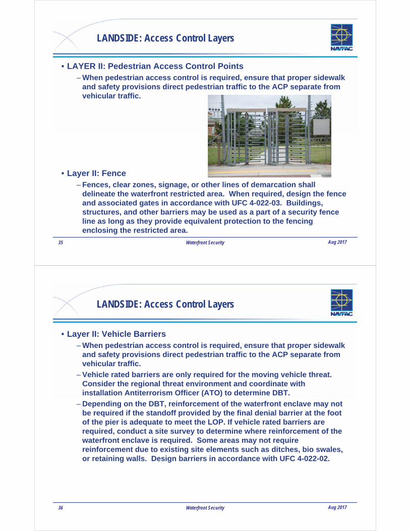
• LAYER II: Pedestrian Access Control Points– When pedestrian access control is required, ensure that proper sidewalk
and safety provisions direct pedestrian traffic to the ACP separate from vehicular traffic.
• Layer II: Fence– Fences, clear zones, signage, or other lines of demarcation shall
delineate the waterfront restricted area. When required, design the fence and associated gates in accordance with UFC 4-022-03. Buildings, structures, and other barriers may be used as a part of a security fence line as long as they provide equivalent protection to the fencing enclosing the restricted area.
36 Waterfront Security Aug 2017
LANDSIDE: Access Control Layers
• Layer II: Vehicle Barriers– When pedestrian access control is required, ensure that proper sidewalk
and safety provisions direct pedestrian traffic to the ACP separate from vehicular traffic.
– Vehicle rated barriers are only required for the moving vehicle threat. Consider the regional threat environment and coordinate with installation Antiterrorism Officer (ATO) to determine DBT.
– Depending on the DBT, reinforcement of the waterfront enclave may not be required if the standoff provided by the final denial barrier at the foot of the pier is adequate to meet the LOP. If vehicle rated barriers are required, conduct a site survey to determine where reinforcement of the waterfront enclave is required. Some areas may not require reinforcement due to existing site elements such as ditches, bio swales, or retaining walls. Design barriers in accordance with UFC 4-022-02.
37 Waterfront Security Aug 2017
LANDSIDE: Access Control Layers
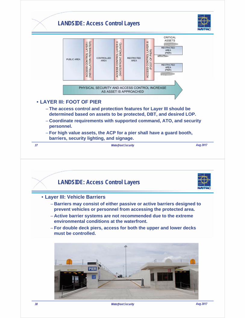
• LAYER III: FOOT OF PIER– The access control and protection features for Layer III should be
determined based on assets to be protected, DBT, and desired LOP.
– Coordinate requirements with supported command, ATO, and security personnel.
– For high value assets, the ACP for a pier shall have a guard booth, barriers, security lighting, and signage.
38 Waterfront Security Aug 2017
LANDSIDE: Access Control Layers
• Layer III: Vehicle Barriers– Barriers may consist of either passive or active barriers designed to
prevent vehicles or personnel from accessing the protected area.
– Active barrier systems are not recommended due to the extreme environmental conditions at the waterfront.
– For double deck piers, access for both the upper and lower decks must be controlled.

39 Waterfront Security Aug 2017
LANDSIDE: Access Control Layers
• Layer III: Guard Booth– A guard booth is a structure that provides a protected position to
facilitate surveillance, assessment, and response to threats. It may be fixed or temporary/portable.
– Location and elevation of the guard booth must enhance the ability of security personnel to process vehicles and personnel.
– Design guard booth to provide maximum visibility of the approach to the guard position and pier deck from the interior.
– Provide overhangs sized to reduce glare on glazing, facilitate mounting of exterior lighting, and provide cover from the elements for security personnel.
40 Waterfront Security Aug 2017
LANDSIDE: Access Control
** If standoff from the asset is achieved at the foot of the pier for the DBT, vehicle rated barriers at the restricted area boundary may not be required.
41 Waterfront Security Aug 2017
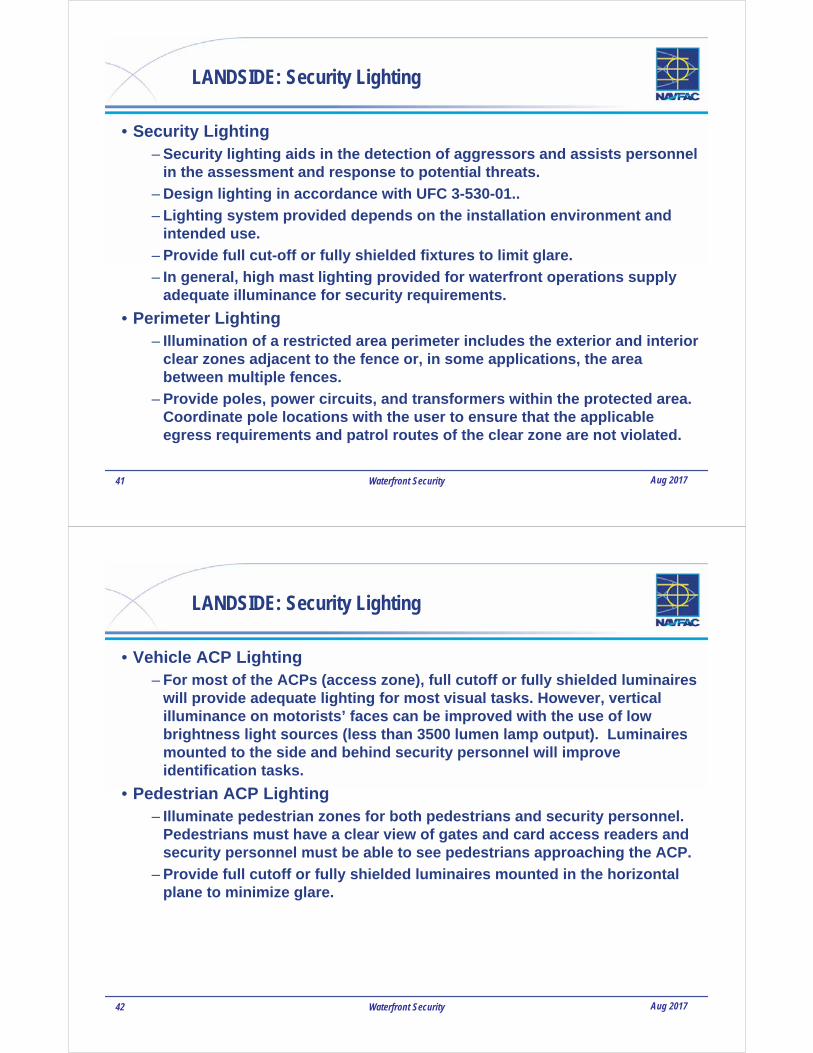
LANDSIDE: Security Lighting
• Security Lighting– Security lighting aids in the detection of aggressors and assists personnel
in the assessment and response to potential threats.
– Design lighting in accordance with UFC 3-530-01..
– Lighting system provided depends on the installation environment and intended use.
– Provide full cut-off or fully shielded fixtures to limit glare.
– In general, high mast lighting provided for waterfront operations supply adequate illuminance for security requirements.
• Perimeter Lighting– Illumination of a restricted area perimeter includes the exterior and interior
clear zones adjacent to the fence or, in some applications, the area between multiple fences.
– Provide poles, power circuits, and transformers within the protected area. Coordinate pole locations with the user to ensure that the applicable egress requirements and patrol routes of the clear zone are not violated.
42 Waterfront Security Aug 2017
LANDSIDE: Security Lighting
• Vehicle ACP Lighting– For most of the ACPs (access zone), full cutoff or fully shielded luminaires
will provide adequate lighting for most visual tasks. However, vertical illuminance on motorists’ faces can be improved with the use of low brightness light sources (less than 3500 lumen lamp output). Luminaires mounted to the side and behind security personnel will improve identification tasks.
• Pedestrian ACP Lighting– Illuminate pedestrian zones for both pedestrians and security personnel.
Pedestrians must have a clear view of gates and card access readers and security personnel must be able to see pedestrians approaching the ACP.
– Provide full cutoff or fully shielded luminaires mounted in the horizontal plane to minimize glare.

43 Waterfront Security Aug 2017
Waterfront Attack
TERRORISTTHE ONE IN THE SMALL BOAT
44 Waterfront Security Aug 2017
Waterside: General Design Strategy
• Prevent waterfront attack by defining a perimeter and applying the defense in depth concept.
• Establish security zones from the high water mark to the waterside installation perimeter and beyond. Security zones are defined as follows:
– Waterside Assessment Zone: An area beyond the DoD’s property line from where surface and subsurface threats approaching the waterside warning zone may be detected, monitored, and tracked.
– Waterside Warning Zone: The area just outside the Threat Zone and within the waterside installation perimeter. In some locations a large warning zone is not feasible due to channel constraints.
– Waterside Threat Zone: The area between a line of floating barriers and an asset.
• The Installation Commander defines the limits of the Threat and Warning zones.

45 Waterfront Security Aug 2017
Waterfront Zones
46 Waterfront Security Aug 2017
Waterside: Design Strategy
• Waterside Standoff– Establish waterside standoff based on DBT. Ideally, this standoff
distance extends from the protected assets to the maximum range of anticipated DBT (25 meters for small explosives to several thousand meters for portable anti-tank weapons).
• Perimeter– Establishing a perimeter is an important protective measure meant to
deter and prevent unauthorized personnel from entering a DoD installation.
• Waterside Perimeter– Delineate the waterside perimeter by issuing a notice to mariners and
with floating signage, signs on piles or other lines of demarcation to prevent innocent vessels from entering the Warning Zone. Methods of demarcation depend on the waterfront geography and the relation between installation and the navigational channel.

47 Waterfront Security Aug 2017
Waterside: Design Strategy
• Waterside Restricted Area– The waterside restricted area may be the waterside perimeter or an
enclave within that perimeter (Threat Zone). Identify waterside restricted area(s) with buoys and signs. Consider using a floating line of demarcation (LOD) to identify the waterside restricted area.
• Line of demarcation (LOD)– A LOD is a system used to identify
restricted waters, standoff distance, or an installation’s waterside perimeter.
– LOD may be located at the perimeter of the Threat or Warning Zone. Coordinate location and requirement on floating LOD with installation.
48 Waterfront Security Aug 2017
Waterside: Design Strategy
• Boat Barrier System– A boat barrier system is a continuous, modular LOD intended to stop
and/or delay waterborne threats. When required by DOD, GCC, or Service Instruction, provide boat barriers at the Threat Zone perimeter to prevent direct unchallenged access to waterfront assets.
– Attempting to cross a boat barrier establishes intent and provides time for security forces to arrive and escort the threat out of the area.
– Many DoD controlled waterfronts do not allow comprehensive waterside security layering due to proximity of waterfront restricted area to shipping channels.

49 Waterfront Security Aug 2017
Barriers
Dunlop Barrier
50 Waterfront Security Aug 2017
Barriers to Stop Rapidly Moving Boats
Port Security Barrier (PSB)

51 Waterfront Security Aug 2017
Port Security Barrier (PSB)
52 Waterfront Security Aug 2017
Barriers or Booms for Setting Boundaries

53 Waterfront Security Aug 2017
Fixed Waterfront Barriers
54 Waterfront Security Aug 2017
DoD Waterfronts

55 Waterfront Security Aug 2017
DoD Waterfronts
56 Waterfront Security Aug 2017
DoD Waterfronts

57 Waterfront Security Aug 2017
Boat Barrier Systems
For more information on boat barrier systems and related products contact:
Waterfront Security Manager
Naval Facilities and Expeditionary Warfare Center, Code CIOFP2
1000 23rd Ave, Bldg. 1100
Port Hueneme, CA 93043
Current POC:
Chip Nixon
805-982-1259
58 Waterfront Security Aug 2017
GUARD TOWERS
• Guard towers provide an elevated protected position to facilitate surveillance, assessment, and response to waterside threats. This position may be fixed or temporary/portable.
• Guard towers are not required at all locations. When required, there should be enough guard towers on the waterfront to ensure complete overlapping coverage of the protected area.
• Coverage should be such that the elimination of one guard tower does not preclude complete coverage.
– Locate and set the elevation of the guard tower to enhance the ability of security personnel to observe and assess threats, initiate alarms, coordinate response, and attack with force, if necessary and authorized.
– Coordinate the number and location guard towers with security personnel, waterfront operations, and EHSS infrastructure. Ensure towers have proper line of sight, are suitable for port operations, account for variations in port loading, and are suitable for port operations.

59 Waterfront Security Aug 2017
GUARD TOWERS
• In most cases, locate the guard tower at or near the end of the pier (head) to maximize visibility of the waterside restricted area.
• Provide 360-degree visibility from the interior of the guard tower and an open observation deck with overhang to facilitate assessment and engagement of threat, maintenance of watch position glazing, and access to roof mounted equipment.
• Size the overhang to reduce glare on glazing and provide cover from the elements for security personnel.
• Size the overhang to reduce glare on glazing and provide cover from the elements for security personnel.
60 Waterfront Security Aug 2017
WATERFRONT: Security Lighting
• In general, high mast lighting provided for waterfront operations supply adequate illuminance for security requirements.
• Provide full cut-off or fully shielded fixtures to limit glare.
• Coordinate number, height, and location of poles and the associated concrete pedestals to minimize obstructions to pier and wharf operations.
• Refer to UFC 4-152-01 for Pier and Wharf operational lighting requirements and UFC 3-530-01 for lighting design criteria.
• Additional lighting (fully shielded or full cutoff) may be required on guard tower (below observation deck) to illuminate egress and the area on the opposite side from high mast lighting.
• Coordinate security lighting requirements with security personnel.

61 Waterfront Security Aug 2017
WATERFRONT: Security Lighting
• Water surface Lighting–High mast lighting on piers and wharfs provide adequate
illumination for security requirements. Glare, poor distribution, and excessive light levels reduce security personnel’s ability to assess surface and subsurface threats.
• Underwater Lighting–Underwater lighting is not normally required for detection of
subsurface threats and is discouraged due to limited benefit, high installation cost, and maintenance issues.
• Under deck Lighting–Dedicated luminaires located beneath the pier are not normally
required and are discouraged due to limited benefit, high installation cost, maintenance cost and environmental issues.
62 Waterfront Security Aug 2017
ELECTRONIC HARBOR SECURITY SYSTEMS (EHSS)
• EHSS is provided when required by DOD, GCC, or Service Instruction.
• EHSS integrates electronic sensors and video systems to detect, assess, track, and archive capabilities for waterside surface and subsurface threats.
• The type of system utilized shall be based on assets to be protected and risk.
• The EHSS can be configured to integrate all sensor and video information to provide a graphical display of all threats within waterside security zones to be protected (protected area). The waterside security zones may be programmed to generate alarm conditions dependent on location of threat relative to protected assets.

63 Waterfront Security Aug 2017
ELECTRONIC HARBOR SECURITY SYSTEMS (EHSS)
• As with all protection measures, the capability and configuration of the EHSS is dependent on the assets to be protected, DBT, port configuration, operations tempo, environmental constraints, and response capability. For more information on related products contact:
Waterside Security Systems
Space and Naval Warfare Systems Center, Code 71742
53560 Hull Street
San Diego, CA 92152-5001
(619) 553-5033 voice
64 Waterfront Security Aug 2017
ELECTRONIC HARBOR SECURITY SYSTEMS (EHSS)
• Surface Detection and Assessment– Radar and video equipment are used to detect, track and assess surface
threats within the protected area.
– Radar and video systems should be located based on site specific conditions such as landside and waterside operations, landside and waterside terrain, climate, available power and communications, and technology capabilities.
– When available, equipment should be roof mounted on the guard towers to provide a solid elevated mounting platform and enclosed space for the related equipment.
• Radar– The radar element is the primary means for detecting surface threat.
Systems include a radar set, tracking processor, and display. The tracking processor has acquisition zones that can be configured for each site based on local geography, port activity, and the installation’s security protocols.
– The radar element should utilize multiple radar transponders installed at various locations to provide a complete picture of the protected zone.

65 Waterfront Security Aug 2017
ELECTRONIC HARBOR SECURITY SYSTEMS (EHSS)
66 Waterfront Security Aug 2017
ELECTRONIC HARBOR SECURITY SYSTEMS (EHSS)
• Video Imaging– Imaging system is a collection of cameras, recorders, switches,
keyboards, and monitors that allow assessment and recording of security events.
– Imaging system is normally integrated into the overall EHSS and monitored at operator workstation.
– Capabilities of the imaging systems include assessment of alarm conditions, surveillance of the protected area, and archiving of events.
– When integrated with video analytics the imaging system can have a detection capability.
– The basic imaging element consists of two cameras. One low light color; pan, tilt, zoom (PTZ) camera for daytime assessment and one PTZ night vision camera or imaging device at each location.
– Multiple technologies must be deployed to ensure adequate coverage of the waterside area. Available technologies include low-light cameras, infrared cameras, thermal imagers, and near infrared laser-camera systems.

67 Waterfront Security Aug 2017
ELECTRONIC HARBOR SECURITY SYSTEMS (EHSS)
• Subsurface Detection and Assessment– The subsurface element detects an underwater threat. Current designs
make use of underwater soundheads connected to signal processors for eventual display.
– Ensure proper Environmental permitting has been obtained to ensure conformance with the “Marine Mammal Protection Act (MMPA).
• Sonar– The sonar transponders are the
primary means for detecting subsurface targets.
– Submerged non-visual elements include the use of sonar transponders installed at various underwater locations feeding their inputs to a central display (operator workstation).
– An environmental assessment must be completed prior to the deployment of any sonar transponders.
68 Waterfront Security Aug 2017
ELECTRONIC HARBOR SECURITY SYSTEMS (EHSS)

69 Waterfront Security Aug 2017
ELECTRONIC HARBOR SECURITY SYSTEMS (EHSS)
• Infrastructure– Infrastructure includes the permanent facilities necessary to support
the EHSS including mounting structures, power, communication cabling (connectivity), pathways, and space for workstations and rack mounted equipment.
– Vehicles including forklifts and container carriers operate in all areas of a pier. Electrical gear located on pier decks have suffered casualty due to forklift tines and crane hooks.
– Minimize equipment mounted on the operational pier deck.
– Any deck mounted equipment must be approved by the Port Ops Officer.
• Location– For double deck piers, the generator and electronic equipment
enclosure shall be located to the lower deck, within the guard tower, or located on the offshore side of the guard tower to minimize the total footprint, and enable the guard tower walls to be used for mounting the conduit system.
70 Waterfront Security Aug 2017
ELECTRONIC HARBOR SECURITY SYSTEMS (EHSS)
• Space– Space must be reserved in multiple locations to support the equipment
and operation of the EHSS. This includes locations such as guard towers, piers, wharfs, and a central monitoring location.
• Guard Towers– Provide space for roof mounted equipment and weather tight
pathways from the roof to the sensor equipment cabinet for associated communication and power cabling, See Figure 5-6. Provide a minimum of two 2 inch (50 mm) conduit per element (imaging, radar, and/or sonar) from sensor equipment cabinet to element location.
– Provide space for a 19 inch (48 cm) telecommunications cabinet (sensor equipment cabinet) sized for the associated EHSS equipment.
– Consider providing space on first floor of guard tower for EHSS generator and controls. If the generator is located in guard tower, provide ventilation, vibration, an acoustic isolation from guard position.
71 Waterfront Security Aug 2017
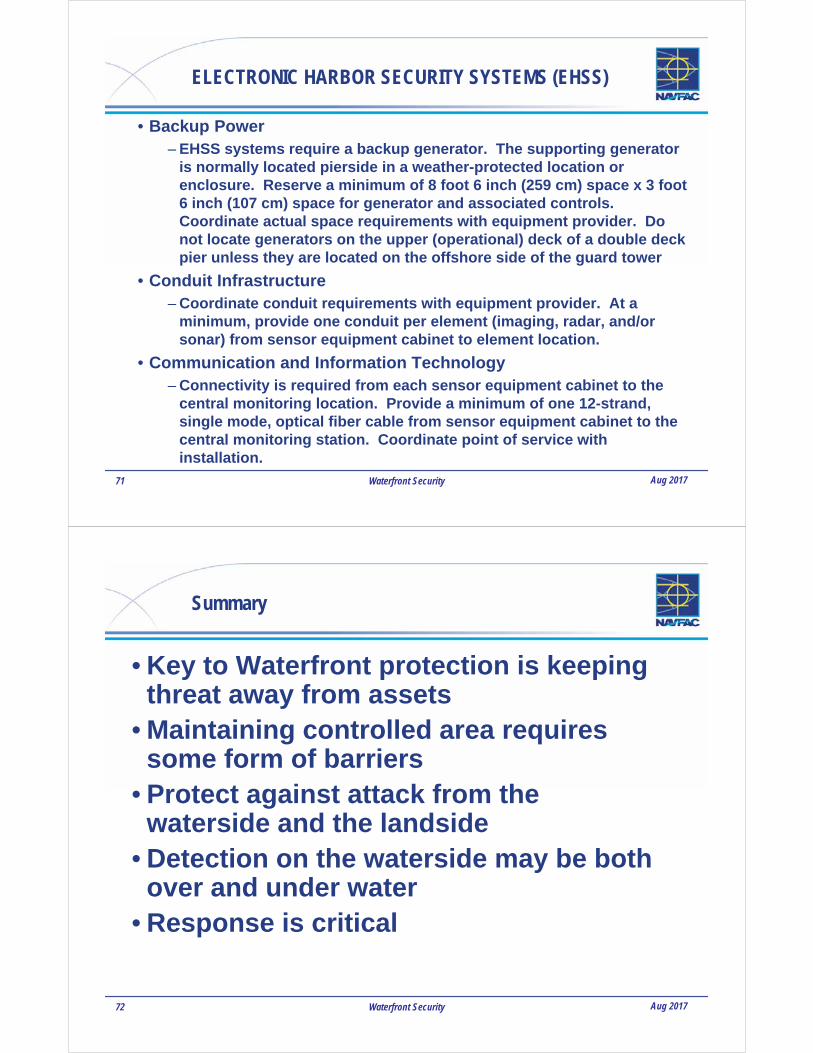
ELECTRONIC HARBOR SECURITY SYSTEMS (EHSS)
• Backup Power– EHSS systems require a backup generator. The supporting generator
is normally located pierside in a weather-protected location or enclosure. Reserve a minimum of 8 foot 6 inch (259 cm) space x 3 foot 6 inch (107 cm) space for generator and associated controls. Coordinate actual space requirements with equipment provider. Do not locate generators on the upper (operational) deck of a double deck pier unless they are located on the offshore side of the guard tower
• Conduit Infrastructure– Coordinate conduit requirements with equipment provider. At a
minimum, provide one conduit per element (imaging, radar, and/or sonar) from sensor equipment cabinet to element location.
• Communication and Information Technology– Connectivity is required from each sensor equipment cabinet to the
central monitoring location. Provide a minimum of one 12-strand, single mode, optical fiber cable from sensor equipment cabinet to the central monitoring station. Coordinate point of service with installation.
72 Waterfront Security Aug 2017
Summary
• Key to Waterfront protection is keeping threat away from assets
• Maintaining controlled area requires some form of barriers
• Protect against attack from the waterside and the landside
• Detection on the waterside may be both over and under water
• Response is critical

73 Waterfront Security Aug 2017
QUESTIONS?