uex corporation technical report on the shea c …
TRANSCRIPT
UEX CORPORATION
Suite 1007, 808 Nelson Street Vancouver, B.C.
Canada V6Z 2X2 Phone/fax 604-669-2349
TECHNICAL REPORT ON THE SHEA CREEK PROPERTY, NORTHERN SASKATCHEWAN
Prepared for UEX Corporation
By
David A. Rhys, M.Sc., P.Geo
Leo Horn, B.Sc., AusIMM
and R. Sierd Eriks, B.A. (Geol.), P. Geo
April 3, 2009

Shea Creek property
I
TABLE OF CONTENTS
SUMMARY VI 1.0 INTRODUCTION 1
1.1 Sources of information 1 1.2 Scope of involvement of the authors
2.0 RELIANCE ON OTHER EXPERTS 2 3.0 PROPERTY DESCRIPTION AND LOCATION 2
3.1 Property location 2 3.2 Concession descriptions 2 3.3 Title and option agreement 5 3.4 Other property interests 6 3.5 Environmental liabilities 6 3.6 Annual expenditures 6 3.7 Permits for exploration 6
4.0 ACCESSIBILITY, CLIMATE, LOCAL RESOURCES, INFRASTRUCTURE
AND PHYSIOGRAPHY 7
4.1 Accessibility and Infrastructure 7 4.2 Climate, vegetation and physiography 7
5.0 HISTORY 9
5.1 Early history of exploration in the Shea Creek area 9 5.2 Exploration on the Shea Creek property, 1990 to present 10 5.3 Historical Resources 13 5.4 Production 13
6.0 GEOLOGICAL SETTING 13
6.1 Regional Geological Setting 13 6.1.1 Regional deformation history and architecture 14 6.1.2 Post-metamorphic Athabasca sandstone 16 6.1.3 Post-Athabasca faulting 16 6.1.4 The Carswell structure 17
6.2 Shea Creek Property geology: distribution and character of lithologies 17 6.3 Structural geology of the Shea Creek property: syn-metamorphic deformation 23
6.3.1 D1 deformation 23 6.3.2 D2 deformation 24
6.4 Retrograde shear zones and later brittle faults: controls to uranium mineralization
26
6.4.1 Steeply dipping D3 mylonites and offsets of the Saskatoon Lake conductor 26 6.4.2 Offsets of the Saskatoon Lake conductor 28 6.4.3 Graphitic shear zones and gneissocity parallel concordant mylonites: possible
syn-D3 structures 29
6.4.4 Late faulting: post-Athabasca tectonic activity 31 6.4.5 Patterns of post-Athabasca fault activity 34 6.4.6 Veins and fractures: implications from oriented drill core 39

Shea Creek property
II
7.0 DEPOSIT TYPES 41 8.0 MINERALIZATION 45
8.1 Uranium mineralization styles 45 8.2 Alteration associated with uranium mineralization 58 8.3 Discussion 63 8.4 Gold mineralization 64
9.0 RECENT EXPLORATION 67 10.0 DRILLING 73
10.1 Drilling methodologies 73
10.2 Downhole directional surveys 74 10.3 Radiometric probing of drill holes 74 10.4 Drill hole collar field locations and surveys 75 10.5 Summary of drilling composites and interpretation of results: northern Shea
Creek property 75
10.5.1 Relationship of drilling length to true thickness of mineralized intercepts 76 10.5.2 Drilling in the Anne Deposit area 76 10.5.3 Areas between the Anne and Kianna Deposits (Kianna South) 77 10.5.4 Kianna area 78 10.5.5 58B area 80 10.5.6 Colette area 81
10.6 Drilling in other areas on the Shea Creek property 82 10.7 Relationship between sample length and true thickness 84
11.0 SAMPLING METHOD AND APPROACH 84
11.1 Drill core handling and logging procedures 84 11.2 Drill core sampling 85 11.3 Sample quality, selection, representativity and potential bias 87
12.0 SAMPLE PREPARATION, ANALYSIS AND SECURITY 89
12.1 Sample Preparation 89 12.2 Analytical Procedures 90
12.2.1 Total and partial digestion 90 12.2.2 U3O8 method by ICPOES 91
12.3 Conversion of radiometric probe data to equivalent uranium grade 92 12.3.1 AVP conversion 93 12.3.2 Radiometrics-Grade correlation 94
12.4 Sample Security 96 12.5 Quality control measures 96 12.6 Author’s Opinion on Sampling, Preparation, Security, and Procedures 96
13.0 DATA VERIFICATION 97
13.1 Comparison of analytical techniques 97 13.2 Sample blanks and standards inserted by AREVA 98 13.3 Laboratory internal Quality Assurance and Quality Control 98 13.4 External laboratory check analysis 99

Shea Creek property
III
14.0 ADJACENT PROPERTIES 100 15.0 MINERAL PROCESSING AND METALLURGICAL TESTING 100 16.0 MINERAL RESOURCE AND MINERAL RESERVE ESTIMATES 101 17.0 OTHER RELEVANT DATA AND INFORAMTION 101 18.0 INTERPRETATION AND CONCLUSIONS 101
18.1 Summary and discussion 101 18.2 Exploration potential and targets 102 18.3 Adequacy of drilling data density and reliability 105
19.0 RECOMMENDATIONS 105
19.1 Drilling program 105 19.2 Infill sampling of existing drill core 106 19.3 Budget 106
20.0 REFERENCES 107 Signature page 113 Certificates of Qualified Persons 114

Shea Creek property
IV
LIST OF TABLES
Table 3.1: List of mineral dispositions comprising the Shea Creek property as of the time of writing
5
Table 8.1: Summary of significant gold intercepts with a grade of >3g/Tonne Au and a grade-thickness (Au g/Tonne X meters) of >5 from drill holes on the northern Shea Creek property.
66
Table 9.1: Diamond drilling on the Shea Creek property, 1993-2008 70 Table 19.1: Proposed 2009 Shea Creek exploration budget 106
LIST OF FIGURES
Figure 1.1: Shea Creek Project – Location and Geological Setting 3 Figure 3.1: Mineral disposition map of the Shea Creek property 4 Figure 4.1: Infrastructure and deposits on and adjacent to the Shea Creek property 8 Figure 6.1: Geological setting of the Shea Creek property 15 Figure 6.2: Geology of the northern Shea Creek property 19 Figure 6.3: Schematic cross section looking north which illustrates possible F2 fold architecture
on the Shea Creek property 24
Figure 6.4: Northern Shea Creek property Contoured unconformity elevation in meters below sea level, based on drilling data
32
Figure 6.5: Colette Area – Geology and unconformity elevation 36 Figure 6.6: Kianna and Anne areas – Geology and unconformity elevation 37 Figure 6.7: Plan map of possible effects of pre-Athabasca fault architecture on post-Athabasca
displacement along concordant (R3) graphitic faults. 38
Figure 6.8: Equal area projection of poles to selected structural data measured from oriented drill core in the northern Shea Creek property.
40
Figure 7.1: Schematic cross section through the Sue zones, McClean Lake property showing two different styles of uranium mineralization.
41
Figure 7.2: Schematic cross section through a hypothetical unconformity-hosted deposit illustrating the diagenetic-hydrothermal model for deposit formation.
44
Figure 8.1: Anne Deposit Section 6750N 48 Figure 8.2: Anne Deposit Section 6875N 49 Figure 8.3: Kianna Deposit, north south vertical cross section, looking west. 50 Figure 8.4: Colette South area section 8670N 52 Figure 8.5: Colette main area section 9200N 53 Figure 8.6: Geology of 150/170 levels, Eagle Point mine (plan view) from Rhys (2002), for
comparison to basement mineralization at Shea Creek. 65
Figure 9.1: Contoured DC-resistivity inverted horizontal depth slice at -350 m below sea level for the northern Shea Creek and southernmost Douglas River properties
69
Figure 9.2: Drill Hole Traces in the northern Shea Creek property 71 Figure 9.3: Drilling in outlying parts of the Shea Creek property. 72 Figure 12.1: Anne Deposit – Sermine USURA correlation of Uranium Grade and AVP from
representative composited intervals using the 2008 Anne grade-radiometric correlation.
94
Figure 12.2: Kianna Deposit – Sermine USURA correlation of Uranium Grade and AVP from representative composited intervals using the 2008 Kianna grade-radiometric correlation.
95
Figure 13.1: Scatter plots illustrating correlation between different uranium analytical techniques for 2007 and 2008 geochemical data from sandstone (red) and basement (green) hosted samples.
98
Shea Creek property
V
LIST OF PHOTOGRAPHS Photo 1: Textures of the pelitic gneiss unit, northern Shea Creek property 20 Photo 2: Textures in the lower granitic gneiss (Lower Felsic Gneiss) sequence 22 Photo 3: F2 folds in fresh footwall granitic gneiss. 25 Photo 4: Mylonites in granitic and pelitic gneiss in the northern Shea Creek property 27 Photo 5: Foliation parallel faults in basement rocks. 30 Photo 6: Semi-brittle faulting affecting basal sandstone and chlorite matrix breccias above the
Athabasca unconformity. 34
Photo 7: Unconformity hosted mineralization textures. 46 Photo 8: High grade unconformity uranium mineralization from drill hole SHE-115-03 in the
Kianna Deposit illustrating textures and associated alteration. 47
Photo 9: Kianna Deposit basement mineralization styles. 54 Photo 10: Anne basement mineralization styles. 55 Photo 11: Discordant vein style mineralization in basement rocks. 56 Photo 12: High grade Kianna perched mineralization in drill hole SHE-114-5. 57 Photo 13: Alteration styles, Kianna. 59 Photo 14: Breccias developed in the basal Athabasca sandstone associated with unconformity-
hosted mineralization. 60
APPENDICES
Appendix 1: List of drill holes on the Shea Creek property, 1992-2008 Appendix 2: Composited drill hole intercepts, 1992-2008 drilling at Shea Creek
Shea Creek property
VI
UEX CORPORATION
Suite 1007, 808 Nelson Street Vancouver, B.C.
Canada V6Z 2X2 Phone/fax 604-669-2349
SUMMARY This report was prepared to provide a review of significant exploration results at the Shea Creek property in northern Saskatchewan, in which UEX Corporation (“UEX”) has a 49% interest, to allow filing of a current Form 43-101F1 technical report. The property, which contains the Anne, Kianna and Colette uranium deposits, is located in the western Athabasca Basin of northwestern Saskatchewan approximately 700 km north-northwest of the city of Saskatoon and approximately 20 km east of the border with the province of Alberta. The property is subject to a joint venture agreement between AREVA Resources Canada Inc. (“AREVA”, 51% interest) and UEX (49% interest), with AREVA acting as project operator. The property comprises eleven mineral dispositions totaling 19,581 hectares (196 km2), which are registered to AREVA. It lies within the Athabasca uranium district, one of the most prolific uranium producing regions in the world. UEX acquired its interest in the Shea Creek property through an option agreement (“the Agreement”) which was signed in March, 2004. Under the Agreement, UEX was granted an option to acquire a 49% interest in eight uranium projects located in the Western Athabasca Basin that included Shea Creek from COGEMA Resources Inc. (“COGEMA”), the predecessor to AREVA, by funding C$30 million in exploration expenditures over an eleven year period. Two new projects were staked in late 2004, bringing the total number of projects in the Agreement to ten. Under the terms of the Agreement, UEX granted AREVA a royalty in an amount equal to US$0.212 per pound of future uranium in concentrate produced from the Anne and Colette Deposits, to a maximum total royalty of US$10.0 million payable by UEX. UEX received confirmation from AREVA that the total amount of UEX’s expenditures on AREVA's Western Athabasca Projects exceeded C$30.0 million as of December 31, 2007, fulfilling the terms of the Agreement well ahead of the maximum eleven year period. The Shea Creek property lies thirteen kilometers south of the formerly producing Cluff Lake mine site. It can be accessed year round by all-weather, maintained gravel Provincial highway #955, which passes through the property. A gravel airstrip located to the northeast of the former Cluff Lake mine site is maintained by AREVA and provides year round access to passenger aircraft. Several large lakes in the area allow float/ski plane access in the summer and winter months. Field operations are currently conducted from the former Cluff Lake mine camp, nine kilometers due north of the Shea Creek property. Exploration history The western portions of the Athabasca Basin were initially explored in the 1960’s as exploration activities expanded outward from the established Beaverlodge uranium district utilizing airborne radiometric (scintillometer) surveys. After airborne radiometric surveys in the late 1960’s, ground prospecting followed by drilling led to the discovery the Cluff Lake deposits. Production from the Cluff Lake deposits commenced in 1980 and operations continued until 2002. Total production from the Cluff Lake mine site amounted to 64.2 million lbs U3O8 at an average grade of 0.92% U3O8, from several deposits.

Shea Creek property
VII
Despite its proximity to Cluff Lake, apart from limited surface work and geophysical surveys, systematic exploration on the Shea Creek property did not commence until 1990. That year, Amok Limited (“Amok”) acquired one mineral permit which covered much of the Shea Creek area, and conducted an airborne GEOTEM electromagnetic and magnetic survey over the project area which identified the presence of conductive north-northwest trending zones within basement rocks underlying the Athabasca sandstone sequence. The airborne surveys were followed-up in 1991 and 1992 with ground electromagnetic surveys on several northeast-oriented lines which verified the position and better outlined the conductors identified by the initial airborne survey. Based on these surveys, Amok restaked the area, reducing the mineral permit to twelve individual claims, most of which now comprise the Shea Creek property. Amok drilled several of the EM conductors in 1992, intersecting narrow intervals of uranium mineralization in northern parts of the property located immediately beneath the sub-Athabasca unconformity, as well as promising alteration. In 1993 ownership of the property was transferred to COGEMA, who continued exploration by drilling to the north along the same conductive basement unit – now known as the Saskatoon Lake Conductor – which was associated with the initial mineralized intercept, and identifying significant uranium mineralization in 1994. Between 1994 and 2000, COGEMA drilled more than 95,000 m in 156 drill holes, which resulted in identification of two deposits, Anne and Colette, distributed with other mineralized intercepts over the three kilometer long strike of the Saskatoon Lake Conductor. Between 2000 and 2004, no drilling was carried out, but additional airborne and ground EM surveys were undertaken to further enhance targeting. In March, 2004, COGEMA (since June 6, 2006 named AREVA) and UEX signed the option agreement. Drilling recommenced funded by UEX, and between 2004 and 2008, approximately 66,154 m of drilling in 138 diamond drill holes was completed under management by AREVA. The drilling programs during that period resulted in the discovery and partial delineation of the Kianna Deposit between the Colette and Anne Deposits, and discovery of new areas of mineralization along the prospective corridor between Anne and Colette (e.g. Colette South mineralization, Kianna South). Exploration during this period also included a MEGATEM® survey of the property area, and ground-based geophysical surveys, which included a DC Resistivity survey in 2005 that outlined several significant untested, or poorly tested resistivity lows. The resistivity lows are comparable to those over known areas of mineralization, and may be indicative of alteration related to uranium mineralization. In total, 165,466 m of drilling in 301 drill holes have been completed on the Shea Creek property since systematic exploration began in 1992. Geological setting The Shea Creek property lies within the western Athabasca Basin of northern Saskatchewan. It is underlain by two dominant lithologic elements: (i) polydeformed metamorphic basement rocks of Archean and Proterozoic age, which are overlain by (ii) 400 to 800 meters of flat lying to shallow dipping, post-metamorphic quartz sandstone of the late Proterozoic Athabasca Group, which forms an elongate, east-west 450 km long Proterozoic sedimentary basin that underlies much of northern Saskatchewan and extends into eastern Alberta. Basement rocks in the western Athabasca area that underlie the Shea Creek region comprise Proterozoic orthogneiss and paragneiss of the Lloyd Domain, which forms part of the Rae Structural Province. On the Shea Creek property, basement lithologies trend north-northwest and dip moderately to shallowly west-southwest. They comprise an alternating sequence of granitic gneiss, diorite gneiss, and pelitic gneiss (Kareen Lake Assemblage) which are affected by amphibolite grade metamorphic assemblages. The latter includes the Saskatoon Lake Conductor, a graphite bearing

Shea Creek property
VIII
pelitic gneiss unit which is spatially associated with uranium mineralization. This pelitic gneiss unit in the northern Shea Creek property, where most of the mineralization discovered to date is developed, is 40-80 meters thick and comprises a graphite-rich pelitic gneiss base, with alternating garnet-rich gneiss and aluminous, locally graphitic pelitic gneiss above. It is surrounded in its hangingwall and footwall by garnetiferous granitic gneiss. The gneiss sequence at Shea Creek was affected by at least two dominant periods of deformation prior to the deposition of the Athabasca sandstone:
a) Penetrative syn-metamorphic deformation which occurred in at least two phases (D1 and D2), comprising early layer parallel gneissosity (S1) which dips west-southwest, and a second-phase, possibly progressively developed S2 foliation. S2 is axial planar to minor, dominantly southwesterly verging folds of S1, and frequently transposes S1 foliation resulting in a composite S1-S2 fabric.
b) Development of northeast trending, right-lateral/oblique lower amphibolite to greenschist grade mylonitic shear zones (D3), which include the major Beatty River Shear zone at the southern end of the Shea Creek property, and numerous, parallel northeast trending second and third order narrow dextral mylonitic shear zones developed to the north which offset the Saskatoon Lake Conductor.
Regional relationships and geochronology suggest that D1 and D2 occurred during the 1950-1900 Ma Tahlston orogeny, while formation of D3 dextral regional shear zones occurred in several phases during regional transpressive deformation potentially related to the Hudsonian orogeny between 1900 and 1740 Ma. Offsets associated with the D3 shear zones may have a fundamental, pre-mineralization control on the later position and development of uranium mineralization. The folded basement sequence was eroded and then unconformably overlain by flat-lying, quartz arenite dominated Athabasca Group sandstone between 1769 and 1500 Ma. Below the unconformity at base of the sandstone, regional clay alteration affects the uppermost tens of meters of the basement gneiss sequence defining a probable paleoweathering profile. Post-Athabasca faulting is localized along the pelitic gneiss unit that is host to the Saskatoon Lake Conductor as a series of southwest dipping, carbonaceous reverse faults that are most concentrated along graphitic gneiss (R3 fault) at the base of the unit. These result in a 20 to 50 meter southwest side up zone of distributed displacement of the unconformity, which is manifested in the sandstone column as a broad, open monoclinal fault-related fold. Individual fault surfaces are often localized along foliation parallel, probably D3 age, reverse shear zones in the pelitic gneiss, and are developed as a combination of semi-brittle stylolitic shear zones and clay gouge-filled faults. The semi-brittle, stylolitic fault surfaces extend into the basal Athabasca sandstone where they locally overprint mineralized chlorite-matrix breccias, indicating that this fault activity may have coincided with, and locally outlasted alteration related to uranium mineralization. Post-Athabasca faulting also includes local remobilization of the steeply dipping, northeast trending mylonites which offset the pelitic gneiss unit by further right-lateral displacement, and a series of east-west to east-northeast trending low displacement faults with apparent left-lateral shear sense. These northeast and east-west trending steeply dipping fault sets coincide with the areas of highest grade uranium mineralization at the unconformity, and are host to, or control underlying uranium mineralization in the basement rocks. Their activity and probable interaction with active, foliation parallel R3 reverse faults may have generated structural permeability and

Shea Creek property
IX
extensional settings for the focus of uranium mineralization. In addition, the stylolitic fabrics and reduced assemblages along the R3 faults suggest a phase of syn-tectonic fluid flow which if coeval with uranium mineralization may have been the reduced fluid source that reacted with oxidized fluids from the Athabasca Basin to form the stationary redox fronts in which uranium mineralization is localized. The Athabasca sandstone is affected to the north of the Shea Creek property by the Paleozoic age Carswell structure, a circular, probable meteorite impact structure which resulted in the uplift and significant disruption of the basement rocks. It is here that the past-producing Cluff Lake uranium deposits have been exposed at surface near the disrupted Athabasca unconformity surface. No effects of the Carswell event are present in the Shea Creek area. Uranium mineralization Uranium mineralization on the Shea Creek property is of the unconformity-associated uranium deposit type, which is spatially related to the sub-Athabasca unconformity in the region. These are generally interpreted to result from interaction of oxidized diagenetic-hydrothermal fluids with either reduced basement rocks, and/or with reduced hydrothermal fluids along faults extending upward toward the unconformity in the underlying basement below. Uranium mineralization identified to date on the Shea Creek property lies in northernmost portions of the property, comprising the Anne, Kianna and Colette Deposits and intervening mineralization in between them. These deposits occur along an approximately three kilometer strike length of the north-northwest trending pelitic gneiss unit that is host to the Saskatoon Lake Conductor at depths of 650-800 meters below the current surface beneath the thick sequence of overlying Athabasca Group sandstone. Within this corridor, drilling has been focused in two areas in which semi-continuous mineralization has been traced at the unconformity: a) the Colette and Colette South areas, over a 0.7 km strike length, and b) the Kianna to Anne deposit areas, over a 1.1 km strike length. The area in between the Kianna and Colette Deposits, termed the 58B area, has only been sparsely drilled along it one kilometer strike length, and has high potential for discovery of additional mineralization. Elsewhere on the property, drilling is limited and widely spaced, but mineralization has locally been intersected two kilometers southeast of the Anne Deposit. Mineralization of three styles is developed within these mineralized domains, based on its position with respect to the Athabasca unconformity, and overall morphology. They comprise:
a) Unconformity-hosted uranium mineralization: This is the most widespread style of mineralization identified to date. It forms shallow dipping zones that are developed in the lowermost Athabasca sandstone immediately above the sub-Athabasca unconformity, or straddling the unconformity and extending downward for several meters into the underlying basement gneisses. The mineralization is typically elongate in plan view, occurring at the unconformity over a 40 to 150 m lateral width along the trace of the northeastern margins of the pelitic gneiss unit where it intersects the unconformity, and extending over parts of the footwall granitic gneiss. Mineralization in high grade areas may comprise massive, nodular or blebby pitchblende +/- coffinite +/- yellow U-silicates in a hematite-clay matrix. In lower grade areas, unconformity-hosted mineralization may be disseminated in chlorite-clay-dravite alteration. The mineralization of all grades is often associated with, and occurs within, chlorite-dravite dissolution breccias in the basal sandstone.

Shea Creek property
X
b) Basement-hosted mineralization: This is the second most extensive style of mineralization, occurring in several portions of the Anne Deposit, in a large zone at Kianna, and in the Colette South area. Basement-hosted mineralization is developed mainly in granitic gneiss for up to 200 meters below the sub-Athabasca unconformity, and vertically below the unconformity-hosted mineralization. Some minor mineralization also occurs in the pelitic gneiss unit, often as lenses following southwest dipping fault planes. It is variable in style and morphology, and is associated with areas of intense white to pale green clay-chlorite alteration. Basement mineralization can be either concordant or discordant in style, with the two styles often occurring together, or branching off one another. Concordant basement mineralization, which occurs in the southern Anne and South Colette deposit areas, forms dominantly shallow to moderate dipping west-southwest lenticular zones that are parallel or sub-parallel to gneissosity in the granitic gneiss. This mineralization style may form stacked zones that are separated from, or splay off unconformity-hosted mineralization, and which often follow southwest dipping fault surfaces or lithologic units. Where present, a garnet-amphibolite gneiss (“metabasite”) subunit may be preferentially mineralized. Discordant basement mineralization, which is best developed in the main Kianna basement zone and in the northern Anne Deposit, is defined as steeply dipping, easterly trending mineralized zones of disseminated, nodular and locally massive replacement style pitchblende +/- coffinite +/- hematite +/- U-silicates, and by sets of pitchblende +/- quartz +/- clay veinlets. Core reorientation suggests that the veinlets trend east-northeast with moderate to steep northerly dips, parallel to the discordant zones. Interaction between concordant and discordant mineralization styles forms oreshoots within basement mineralization that plunge moderately to shallowly to the west-southwest.
c) Perched mineralization: Volumetrically, this is the least extensive of the three mineralization styles. It comprises flat-lying, to shallow southwest dipping lenses of disseminated to massive pitchblende-coffinite-hematite-clay mineralization that are developed in Athabasca sandstone up to 60 meters above the sub-Athabasca unconformity. Perched lenses may occur stacked above unconformity mineralization with no associated faulting, or may occur along, or at the termination of, southwest dipping faults where they project upward into the Athabasca sandstone from the pelitic gneiss below.
Where best developed and highest grade, all three mineralization styles may be vertically stacked on top of one another. These stacked, better developed areas of mineralization may be localized in areas where steeply dipping, discordant east-west to northeast trending faults interact with, and intersect the foliation-parallel faults at the unconformity creating zones of high dilatancy and structural permeability. Pre-Athabasca basement structural architecture may play an important role in localizing these higher grade areas. In areas where the Saskatoon Lake Conductor is offset by northeast-trending dextral mylonitic shear zones, faults localized along the conductor may step and splay as they link across the area of offset. In addition, the older shear zones themselves may be remobilized and host, or control adjacent mineralization. Basement mineralized zones may be mantled by sheeted sets of quartz and quartz-dravite veins, although pre-mineralization veins associated with mylonites are also evident. Mineralization is associated with extensive clay alteration which affects the lower sandstone, and extends downward into basement rocks. The principal clay minerals are illite, chlorite, kaolinite, and dravite. Often an early phase of illitization is evident, while kaolinite is generally paragenetically late. Extensive areas of chlorite-clay-dravite matrix breccias occur along the unconformity in the basal sandstone column, and are spatially associated with unconformity-hosted mineralization. The presence of both pitchblende fragments in the breccias, and the

Shea Creek property
XI
overprinting of the breccia matrix by pitchblende-coffinite assemblages indicate a syn-mineralization timing, which was probably also coeval with reverse faulting along the R3 structures. In basement rocks, clay alteration envelops mineralized zones and outlines their general morphology, so modeling of the alteration forms a targeting tool. An extensive northeast-trending and steeply dipping clay alteration zone at Kianna is open to the east and west, and contains to the north unbounded mineralization, providing significant room for expansion of Kianna basement mineralization, and the potential for additional, parallel basement zones. Drilling methods Due to the greater than 600 meter depths to target area, drilling is generally conducted by penetrating overburden with HW diameter casing followed by HQ coring to 400 meters depth. The holes are typically completed by reducing to NQ-sized core (48 mm core diameter) which is the typical core size testing mineralization at target depths. Since 1999, directional drilling utilizing wedge cuts from a master (pilot) drill hole have been completed in areas where closely spaced drill holes are required to define mineralization. The directional drilling process reduces the overall quantity of coring required, and allows controlled drilling of deep targets. As is standard practice in uranium exploration, at the completion of each drill hole, downhole radiometric geophysical probing surveys are performed from the bottom of the hole up through the drill string. Drill hole sampling and analysis Drill core sampling is conducted to industry standards, utilizing geological controls and scintillometer reading to determine position of mineralized intervals and sampling lengths. Mineralized samples, typically at 0.5 meter intervals, are split, with half remaining in the core box, and the other half placed in a sample bag and numbered for geochemical analysis. Samples are analyzed geochemically at the Saskatchewan Research Council Geoanalytical Laboratories (“SRC”) in Saskatoon, an ISO/IEC 17025:2005 accredited facility that is certified by the Canadian Association for Laboratory Accreditation Inc. Samples are analyzed for uranium by ICP-MS (Inductively Coupled Plasma Mass Spectroscopy) for samples with grades lower than 1,000 ppm U, and U3O8 uranium assay by ICP-OES (Inductively Coupled Plasma Optical Emission Spectroscopy) for samples determined by ICP-MS to contain uranium concentrations higher than 1,000 ppm U. In addition to the geochemical analyses, downhole radiometric probe data is available for most drill holes. As is standard practice in uranium exploration in the Athabasca Basin, the probe data can be used to estimate uranium grade when sufficient geochemical data is available to calibrate the probe results to specific mineral deposits or mineralized areas. The converted probe data, which are denoted as “eU3O8”, then form a check for the geochemical data, and allow estimation of the uranium grade of mineralized intervals in areas of poor core recovery where representative sampling is not possible. Composited drilling results in areas of less than 80% core recovery, or where sampling is incomplete, are reported here as equivalent probe data. The conversion formula from probe data to equivalent uranium grades on an exploration project is periodically modified for different deposits and zones as new geochemical data is received. This is the case at Shea Creek, where probe data reported in UEX-AREVA disclosures prior to 2008 utilized a modified conversion coefficient which had been developed by COGEMA in its operations during the 1980’s at the Dominique-Peter Deposit at the Cluff Lake Mine. In early 2008, AREVA calculated specific probe conversion coefficients for the Kianna and Anne Deposits based on geochemical data received up to that time, which replaced the earlier Cluff

Shea Creek property
XII
Lake coefficient. Consequently, the geochemical data reported here, and the probe equivalent grades which are reported here in areas of poor core recovery or incomplete sampling, differ from, and supercede composited intervals reported in 2004 to 2007 joint UEX-AREVA news releases. Several levels of geochemical and probe data verification are currently utilized by AREVA at Shea Creek, including (i) internal SRC laboratory quality assurance and quality control (“QA/QC”), (ii) comparison of the results of the different geochemical analytical techniques for uranium which are routinely received (uranium partial and total by ICP-MS, U3O8 assay by ICP-OES), (iii) comparison to probe results, and (iv) external laboratory check analysis of selected samples. As part of AREVA’s quality improvement programs, a more rigorous geochemical QA/QC program was implemented in 2006, which continues to be followed. Drilling results Drilling on the northern portion of the Shea Creek property has resulted in the intersection of numerous significant areas of uranium mineralization associated within the three kilometer corridor hosting the Anne, Kianna and Colette Deposits. No historical or current N.I. 43-101 complaint resources are available for these deposits, although the proposed drilling programs in 2009 are intended to advance the deposits towards this objective. Drill holes generally have steep dips of 750 or steeper which generally cross the flat-lying lenses of unconformity-hosted and perched mineralization styles at a high angle that is close to, or at true thickness. Mineralized intercepts of discordant basement mineralization have more complex morphology, and in most cases true thickness of intercepts are as yet undetermined although these discordant basement zones can contain combinations of steeply dipping vein-like mineralization which occurs at shallow core axis angles to many drill holes, in combination with foliation parallel, shallower dipping components which may form oreshoots. In the Anne Deposit, some of the more significant drilling intercepts occur in unconformity-hosted mineralization in the southern and northern portions of the Anne Deposits, defining two principal higher grade pods within a broader, lower grade unconformity-hosted mineralized zone. Most significant intercepts in these higher grade areas that are generally at, or close to, true thickness in these areas include the following:
• 11.607% U3O8 over 6.0 m, including 23.964% U3O8 over 2.9 m and 34.694% U3O8 over 1.9 m in hole SHE-087
• 4.411% U3O8 over 14.9 m, including 20.898% U3O8 over 2.9 m in hole SHE-095-03 • 5.419% U3O8 over 19.0 m, including 29.200% U3O8 over 3.4 m in hole SHE-096-03 • 10.027% U3O8 over 8.4 m, including 34.149% U3O8 over 2.3 m and 60.601% U3O8 over
1.2 m, in hole SHE-099 • 5.649% U3O8 over 17.9 m, including 14.547% U3O8 over 6.5 m in hole SHE-099-02 • 3.315% U3O8 over 25.1 m, including 16.866% U3O8 over 4.0 m in hole SHE-100-01 • 4.206% U3O8 over 36.0 m, including 13.703% U3O8 over 6.5 m in hole SHE-122-01 • 3.642% U3O8 over 20.5 m, including 11.407% U3O8 over 6.0 m in hole SHE-122-05
Basement mineralization at Anne is mainly concordant in style and occurs under the highest grade pods of unconformity mineralization described above. In southern portions of the Anne Deposit, the mineralization is mainly of the concordant basement style, while in the north it represents a combination of the concordant and discordant styles for which true thickness is

Shea Creek property
XIII
generally undetermined. Principal intercepts include the following, which mainly lie beneath the northern pod of higher grade unconformity mineralization:
• 3.244% U3O8 over 9.0 m, including 10.159% U3O8 over 2.0 m in hole SHE-088 • 4.553% U3O8 over 3.9 m, including 7.925% U3O8 over 2.2 m in hole SHE-094-01 • 5.740% U3O8 over 2.8 m, including 14.089% U3O8 over 0.9 m in hole SHE-094-06 • 1.044% U3O8 over 19.8 m, including 5.511% U3O8 over 1.7 m in hole SHE-095-03 • 3.639% U3O8 over 7.5 m, including 16.954% U3O8 over 0.6 m in hole SHE-100-01 • 23.171% U3O8 over 3.5 m, and 3.512% U3O8 over 8.5 m in hole SHE-122-01 • 3.569% U3O8 over 4.0 m, including 6.661% U3O8 over 1.5 m in hole SHE-122-04
Over the 400 meter distance between the Anne Deposit and the Kianna Deposit to the northwest, only 31 drill holes have been completed which are variably, but generally widely, spaced. Drilling suggests that at least low grade uranium mineralization is continuous at the unconformity between the two deposits in this area, but several may represent additional, as yet undefined higher grade zones. These include intercepts of unconformity-style mineralization of 3.662% U3O8 over 5.3 m in hole SHE-102-02, 11.114% U3O8 over 3.6 m in hole SHE-123-06, and 5.198% U3O8 over 3.3 m hole SHE-123-07, which form the core of an as yet not fully defined zone approximately 150 m southeast of the Kianna Deposit. Significant basement intercepts lie beneath this zone in an east-northeast trending zone of clay alteration, and include 4.841% U3O8 over 3.5 m in hole SHE-123-02, for which the true thickness and extent of mineralization are currently unknown. The Kianna Deposit contains stacked perched, unconformity and basement mineralization which lie in an east-northeast trending corridor which corresponds with a large zone of basement clay alteration. Perched mineralization here forms at least two pods, including one high grade pod which has plan view dimensions of approximately 60 by 30 meters, and contains intercepts at or close to true thickness in this lens that include:
• 20.721% eU3O8 over 10.2 m, in hole SHE-114-05 • 7.367% U3O8 over 9.5 m in hole SHE-114-07 • 4.637% eU3O8 over 22.2 m, in hole SHE-114-09 • 4.580% eU3O8 over 15.3 m, in hole SHE-114-11 • 8.420% eU3O8 over 12.6 m in hole SHE-115-18
Beneath the perched mineralization, mineralization at Kianna forms a high-grade lens that lies above the basement mineralization. Significant intercepts, which are close to true thickness, occur over a 70 (north-south) by 150 meter (east-west) area in plan view, include:
• 9.335% U3O8 over 12.2 m over 4.3 m in hole SHE-115-03 • 2.547% U3O8 over 19.0 m in hole SHE-115-04 • 7.827% U3O8 over 7.2 m, including 20.360% U3O8 over 2.7 m in hole SHE-115-05 • 2.227% U3O8 over 10.6 m in hole SHE-115-06 • 6.297% U3O8 over 7.9 m in hole SHE-118 • 2.275% U3O8 over 11.5 m in hole SHE-118-09
The most significant extensive mineralization at Kianna occurs in an east-northeast trending zone of basement hosted mineralization which extends to at least 200 meters below the unconformity and has a strike length of approximately 180 meters as defined to date. Significant intercepts in

Shea Creek property
XIV
this zone are listed below. The true thickness of many of these intercepts is unknown; some are drilled at shallow angles to mineralization.
• 3.578% U3O8 over 11.8 m and 5.776% U3O8 over 6.5 m in hole SHE-114-08 • 4.093% U3O8 over 45.0 m, including 18.073% U3O8 over 6.0 m in hole SHE-114-11 • 4.382% U3O8 over 7.8 m, including 20.023% U3O8 over 1.5 m in hole SHE-114-17 • 6.268% U3O8 over 3.5 m, including 40.086% U3O8 over 0.5 m in hole SHE-115-01 • 3.643% U3O8 over 4.5 m, including 30.418% U3O8 over 0.5 m in hole SHE-115-05 • 1.059% U3O8 over 15.0 m, and 2.206% U3O8 over 7.5 m in hole SHE-115-08 • 1.840% U3O8 over 22.0 m, including 15.193% U3O8 over 1.5 m in hole SHE-115-09 • 8.581% U3O8 over 15.0 m, including 24.346% U3O8 over 2.5 m in hole SHE-115-10 • 3.731% U3O8 over 10.0 m, including 22.322% U3O8 over 1.5 m in hole SHE-115-15A • 2.188% U3O8 over 9.5 m, including 7.951% U3O8 over 2.5 m in hole SHE-118-08 • 19.244% U3O8 over 1.0 m in hole SHE-118-15
The high grade intercept in hole SHE-114-17 listed above is an isolated, largely open intercept which may form a separate, and new east-northeast trending zone to the north of the main zone of basement mineralization, or could be linked southward in a drilling gap to the main zone. Only 18 drill holes have been completed in the one kilometer strike between the Kianna and southern Colette Deposits in this area. Best intercepts in the area have occurred around drill hole SHE-058B, which is located 600 meters north-northwest of Kianna and 400 meters southeast of the Colette South area. In addition to intersecting 8.8 m of lower grade unconformity-hosted mineralization, SHE-058B intersected multiple mineralized intervals in the basement, including 2.213% U3O8 over 2.6 m, that also included 6.732% U3O8 over 0.7 m; true thickness and orientation of mineralization are unknown. Overall style and alteration intensity suggest high potential for further basement mineralization here, which is open in all directions. The closest drill holes to hole SHE-058B are of the SHE-103 and SHE-104 series, 50 to 200 meters to the northwest and southeast, which have locally intersected unconformity (e.g. 0.242% eU3O8 over 28.2 m in hole SHE-103-01) and basement (0.470% eU3O8 over 5.8 m in hole SHE-104-03) mineralization. Testing of this area remains a high priority for exploration. The northwestern portion of the prospective corridor at Shea Creek contains the Colette Deposit. Colette contains two components, an unconformity-hosted style of mineralization distributed over a 0.5 kilometer strike length, and at its southeastern end, stacked concordant zones of basement mineralization along a 250 meter strike length which have recently been identified and which are largely still open downdip. Like other parts of Shea Creek, the best intercepts at the unconformity lie in two east-northeast trending corridors at the southeastern and northwestern ends of the Colette Deposit associated with discordant faults, and include:
• 1.432% U3O8 over 12.2 m, including 2.916% U3O8 over 5.6 m in hole SHE-045 • 2.342% U3O8 over 16.8 m, including 4.294% U3O8 over 7.8 m and 7.547% U3O8 over 2.7
m in hole SHE-052 • 4.099% U3O8 over 6.6 m, including 6.493% U3O8 over 3.9 m in hole SHE-059 • 1.732% U3O8 over 11.9 m, including 3.476% U3O8 over 4.6 m in hole SHE-065 • 1.122% U3O8 over 11.0 m in hole SHE-078 • 1.517% U3O8 over 8.9 m in hole SHE-091
Shea Creek property
XV
Significant basement intercepts in the southern area of dominantly concordant basement mineralization include:
• 0.907% eU3O8 over 10.8 m, including 3.91% eU3O8 over 1.2 m in hole SHE-111-02 • 0.582% eU3O8 over 16.2 m and 2.458% U3O8 over 1.0 m in hole SHE-111-05 • 3.227% U3O8 over 8.0 m, including 12.380% U3O8 over 0.5 m and 23.934% U3O8 over
0.5 m in hole SHE-111-06 • 1.429% U3O8 over 6.0 m, and 0.633% U3O8 over 4.5 m in hole SHE-111-11 • 0.879% U3O8 over 11.5 m, including 4.810% U3O8 over 1.0 m in hole SHE-111-12
In addition to uranium, Shea Creek mineralization locally contains high gold grades, although the morphology and true thickness of areas which are high in gold content are as yet undetermined. These frequently, but not always, occur in areas of higher grade uranium mineralization, and can be present both in unconformity and basement mineralization. Significant gold-bearing intercepts include 20.79 g/Tonne Au over 2.40 m in drill hole SHE-087, 14.02 g/Tonne Au over 3.30 m in hole SHE-115-03, 13.75 g/Tonne Au over 2.50 m in hole SHE-079, 9.70 g/Tonne Au over 3.50 m in hole SHE-102 and 5.95 g/Tonne Au over 5.70 m in hole SHE-115-04. However, higher grade uranium mineralization is not consistently gold-enriched. Future work to establish patterns of gold distribution is recommended, especially to identify if any consistent local gold-enriched domains can be recognized which might enhance the potential value of parts of the deposit. Exploration potential and recommendations The Shea Creek property is highly prospective for the discovery of additional uranium mineralization. Several levels of exploration potential are apparent. In known deposits, potential exists to expand the dimensions of high grade pods between, or outward from previous drill holes. Even small expansions by additional drilling to pods of very high grade mineralization that have been encountered can have a very material affect on their estimated total uranium content. Therefore, infill and nearby step-out drilling in some of these areas is recommended. Exploration potential exists for step-out drilling into open areas of mineralization, for example to expand the Kianna basement zone, and to test open mineralization downdip in the Colette area. Gaps in drilling along the main prospective corridor between Anne and Kianna, and between Kianna and Colette also have high potential for new discoveries for both mineralization at the unconformity and in basement rocks. In these areas, modeling of the distribution and intensity of clay alteration in basement rocks, as well as the structural setting of local areas as exploration proceeds will aid in targeting for new zones of basement mineralization. In both the prospective three kilometer corridor in the northern part of the Shea Creek property, and other areas to the south along the Saskatoon Lake Conductor, potential may also exist for significant areas of basement mineralization which have little or no expression at the unconformity. In the eastern Athabasca Basin, large zones of basement mineralization in extensional vein sets and replacement zones may develop in basement rocks along strike from mineralized zones that occur at the unconformity. These basement zones are localized along steeply dipping faults and veins that pass obliquely across the metamorphic sequence. This is the case with the numerous northeast-trending and potential east-west trending faults at Shea Creek. It implies potential for basement-hosted mineralization in other areas, such as to the southeast of the Anne Deposit, where broad zones of anomalous geochemistry and favorable alteration have been intersected, but no significant mineralization has yet been identified at the unconformity.

Shea Creek property
XVI
In other areas on the Shea Creek property where little or no drilling has occurred, exploration is in its early stages and targets are mainly geophysical (EM conductors and resistivity). Prospective areas of low resistivity with a similar signature to the area around the Anne, Kianna and Colette Deposits occur along the Klark Lake Conductor in northwestern parts of the property. Low resistivity zones lying between the Saskatoon Lake and Klark Lake Conductors also form prospective targets that could represent alteration along discordant fault zones. Expansion of resistivity surveys to other parts of the property is recommended to further identify other low resistivity targets. The recommended work program for 2009 on the Shea Creek property would comprise a combination of a) infill and step-out drilling to further advance the deposits toward a future N.I. 43-101 compliant resource estimate, and b) exploration drilling along the prospective three kilometer corridor in the northern Shea Creek property. A drilling program of approximately 15,500 meters with six pilot holes (each 900 m average length) and 26 navigational cuts (each approximately 350 to 400 m in length) is recommended. In areas of infill and step-out drilling, many of the proposed holes could be drilled as cuts from existing pilot drill holes. In addition, infill sampling of previously unsampled intervals in mineralized zones is recommended to provide a more comprehensive geochemical database for future resource work. Costs for the 2009 drilling program, are estimated at approximately C$8.26 million, of which UEX, as 49% partner, is responsible for C$4.05 million.
Shea Creek property 1
1.0 INTRODUCTION (Form 43-101F1 item 4) This report provides a technical review of the geology and exploration results received from exploration of the Shea Creek property in the western Athabasca Basin of Northern Saskatchewan (Figure 1.1). The property is owned 49% by UEX Corporation (“UEX”) and 51% by AREVA Resources Canada Inc. (“AREVA”). The report was prepared for UEX to provide a review of, and supporting information for, exploration results on the Shea Creek property to allow filing of a current Form 43-101F1 technical report in accordance with National Instrument 43-101 (“N.I. 43-101”) requirements concerning disclosure of technical information regarding material properties. 1.1 Sources of information The Shea Creek property has been subject to ongoing exploration programs conducted since 1990. Details of exploration activities on the property are outlined in numerous exploration reports by technical staff of AREVA Resources Canada Inc. (“AREVA”), the operator of the project, which was formerly named COGEMA Resources Inc. (“COGEMA”). In approximate chronological sequence, the principal reports documenting exploration activities, results and interpretations include Koch (1990), Dalidowicz (1991, 1993), Alonso et al. (1992), Alexander et al. (1994, 1995), Baudemont (1996, 2000), Pacquet and Reyx (1995, and petrographic reports in later assessment reports), Munholland et al. (1996), Moriceau (1997), Robbins et al. (1997-2000; 2006-2007), Robbins (2005), Bingham and Koning (2003), Koch (2003), Nimeck (2005), Robbins et al. (2006-2007), Reddy et al. (2007), Modeland et al. (2008), and Koning et al. (2008). These reports are authored or co-authored by Qualified Persons as defined by National Instrument 43-101. In addition to the previous reporting, information in the sections below concerning project geology and uranium mineralization have also been obtained by the authors by direct observation through on-site evaluation of drill core, review and assessment of database information, and geological interpretation of exploration data. This has been augmented by communication with AREVA personnel on technical and logistical aspects of the project. Regional geological setting and context of the Shea Creek property and adjacent Carswell structure are outlined in syntheses by Tona et al. (1985), Bell (1985), Laine (1985), Pagel et al. (1985), Lewry and Sibbald (1980), Baudemont and Fedorowich (1996), Hanmer (1997), Card (2001, 2002, 2006), Card et al. (2007a, 2007b), Ramaekers et al. (2007), and many other reports and papers. Metallogenic setting of the Athabasca Basin region is reviewed by Jefferson et al. (2007). 1.2 Scope of involvement of the authors D. Rhys (P. Geo) and L. Horn (AUSIMM), along with D. Baldwin (AUSIMM) conducted an on site evaluation of drill core between July 28 and August 8, 2008. During this site visit, 153 drill intercepts of lower sandstone and basement rocks in mineralized areas were laid out and quick logged, and selected portions of an additional 23 holes were examined, documenting lithology, alteration, structural features and nature and distribution of mineralization. The drill holes which were examined represented all intercepts available through the Kianna Deposit at that time, all drill holes between the Anne and Collette Deposits, northern parts of the Anne Deposit, and representative drill holes in other parts of the drilling areas including the Colette Deposit. The intent of the work was 1) to provide to UEX an in house review of the geology and exploration potential of the Shea Creek deposits, 2) to ultimately contribute to the geological model of the deposits being formulated by AREVA technical personnel, and 3) to provide the basis for an independent N.I. 43-101 compliant review of the project. At the time of this site visit drilling was
Shea Creek property 2
active on the project, and core handling, sampling and logging methodologies were observed and discussed with AREVA personnel. Subsequently, the authors have conducted office based review and interpretation of exploration data from the property. The report below integrates the observations of the authors with previous and ongoing interpretations by AREVA personnel. Prior to the July-August 2008 evaluation program, Rhys briefly visited the project area on several occasions between 2006 and 2008, while all three authors of this report visited the site on March 28, 2008. S. Eriks (P. Geo) also reviewed results of the July-August field program on site on August 8, 2008. All of the earlier trips involved discussions of exploration results with AREVA personnel, and brief examinations of representative drill core. Responsibility for the writing of individual sections of this report is as follows: Rhys, Sections 10-17, Rhys and Eriks, Sections 1-5 and 18-19; Rhys and Horn, Sections 6-9. Note that the interpretations of the structural geology of the northern Shea Creek property are based on the work and opinions of the authors, and in many cases differ from previous interpretations by AREVA. 2.0 RELIANCE ON OTHER EXPERTS (Form 43-101F1 item 5)
Additional technical information that is beyond the scope, or expertise, of the authors’ work is largely the work of other qualified persons, and is referred through citations in the text below. Information concerning claim status, ownership, and assessment requirements which are presented in Section 3 below, Figure 3.1 and in Table 3.1 have been provided to the authors by AREVA, and have not been independently verified by the authors. However, the authors have no reason to doubt that the title situation is other than what is presented here. 3.0 PROPERTY DESCRIPTION AND LOCATION (Form 43-101F1 item 6) 3.1 Property location
The Shea Creek property is located in the western Athabasca Basin of northwestern Saskatchewan approximately 700 km north-northwest of the city of Saskatoon (Figure 1.1) and approximately 20 km east of the border with the province of Alberta. The property is approximately 230 km north of the town of La Loche and 15 km south of the former producing Cluff Lake mine site. It lies between latitudes 58°00’N to 58°15’N and longitudes 109°15’W to 109°35’W (Figure 1.1), and straddles parts of topographic map sheets 74K/3 and 74K/4 of the Canadian National Topographic system. 3.2 Concession descriptions
The Shea Creek property consists of 19,581 hectares (196 km2) in 11 mineral dispositions (Table 3.1, Figure 3.1). The project is a joint venture between AREVA (51% interest) and UEX (49% interest), with AREVA acting as project operator. All mineral dispositions are registered to AREVA.
The disposition status of the Shea Creek Project is shown in Table 3.1 and includes the dates in which the mineral claims were recorded and when they will expire without the filing of additional assessment expenditures. All dispositions are contiguous and groupings can be made on an annual basis if the dispositions are in good standing. There are no surface rights to any portions of the property.

Shea Creek property 3
Figure 1.1: Shea Creek Project - Location and Geological Setting. Major lithostratigraphic domains and the extent of the Athabasca Basin are illustrated. The project is located in the western portions of the Athabasca
Basin which are underlain by metamorphic rocks of the western Lloyd Domain.

Shea Creek property 4
Figure 3.1: Mineral disposition map of the Shea Creek property. Note other adjacent properties which are held by AREVA and UEX. Grid is NAD83 UTM zone 12.

Shea Creek property 5
Mineral dispositions are located in the field by corner and boundary claim posts which lie along blazed and cut boundary lines. The entire length of the Shea Creek property boundary has not been surveyed. A legal survey is not required under the provisions of the Saskatchewan Mineral Disposition Regulations (1986). The property location is defined on the government claim map. Table 3.1: List of mineral dispositions comprising the Shea Creek property as of the time of writing. The data was provided by AREVA, and has not been independently verified by the authors
Group Disposition Number
Recording Date Area (HA) Annual Assessment Requirement
Next Assessment Due
45586 S-104625 1990-Jan-29 2444 $61,100.00 2014 45586 S-104626 1990-Jan-29 2077 $51,925.00 2014
NO GROUP S-104617 1990-Jan-29 1478 $36,950.00 2026 NO GROUP S-104619 1990-Jan-29 1445 $36,125.00 2024 NO GROUP S-104620 1990-Jan-29 1431 $35,775.00 2024 NO GROUP S-104621 1990-Jan-29 2000 $50,000.00 2024 NO GROUP S-104622 1990-Jan-29 2208 $55,200.00 2024 NO GROUP S-104623 1990-Jan-29 2276 $56,900.00 2024 NO GROUP S-104639 1992-Jun-12 1164 $29,100.00 2024
45608 S-104638 1992-Jun-12 2438 $60,950.00 2025 45608 S-104760 1995-Jun-15 620 $15,500.00 2030
Totals 19,581 $489,525.00 3.3 Title and option agreement In March 2004, AREVA (formerly known as COGEMA Resources Inc., “COGEMA”) and UEX announced the West Athabasca Option Agreement (“Agreement”) whereby UEX was granted an option to acquire a 49% interest in eight uranium projects located in the Western Athabasca Basin of northern Saskatchewan, by funding C$30 million in exploration expenditures (see UEX’s March 18, 2004 news release). Two new projects were staked in late 2004, bringing the total number of projects in the Agreement to ten (see UEX’s January 31, 2005 news release). The ten Western Athabasca Projects (“Projects”) include Shea Creek (containing the Anne and Colette uranium deposits), Douglas River, Erica, Alexandra, Laurie, Mirror River, Nikita, Uchrich, James Creek and Brander Lake, several of which are shown on Figure 3.1. Under the terms of the Agreement, UEX earned a 12.25% interest in the Projects for every C$7,500,000 spent to the maximum total interest in the Projects of 49%. Minimum annual expenditures to fulfill for the Agreement over a maximum 11 year period were stipulated as follows: a) Years 1 & 2: Minimum C$2,000,000 per year; b) Years 3, 4, 5, 6: Minimum C$2,500,000 per year; c) Years 7, 8, 9: Minimum C$3,000,000 per year; and d) Years 10 & 11: Minimum C$3,500,000 per year. Under the terms of the Agreement, UEX also granted AREVA a royalty for the Anne and Colette Deposits, in an amount equal to US$0.212 per pound of uranium in concentrate produced from the Anne and Colette Deposits and delivered to the parties for sale, to a maximum total royalty of US$10.0 million payable by UEX.

Shea Creek property 6
UEX received confirmation from AREVA that the total amount of UEX expenditures on AREVA's Western Athabasca Projects exceeded C$30.0 million as of December 31, 2007 (see January 11, 2008 news release), and fulfilled the terms of the Agreement well ahead of the maximum 11 year period. As a result, the Shea Creek property is now 51% and 49% owned by AREVA and UEX, respectively. Exploration activities on the Shea Creek Project will continue to be managed by AREVA through a Joint Venture Agreement that is currently being negotiated between the two companies. 3.4 Other property interests To the knowledge of the authors, there are no underlying interests, back-in rights, payments, or other agreements on the property. As specified in the Agreement, UEX has granted AREVA a royalty in an amount equal to US$0.212 per pound of uranium in concentrate produced from the Anne and Colette Deposits and delivered to the parties for sale, to a maximum total royalty of US$10.0 million payable by UEX. 3.5 Environmental liabilities The authors are not aware, at the time of writing this report, of any known environmental liabilities on the Shea Creek Property. No mining or waste disposal has occurred on the Shea Creek property, and consequently the property is not subject to any liabilities due to previous mining activities. 3.6 Annual expenditures Annual expenditures of $12.00 per hectare are required for the first 10 years after staking of a claim to retain each disposition. This rate increases to $25.00 per hectare annually after 10 years, a rate which currently applies to the dispositions comprising the Shea Creek property. Required assessment work for each mineral disposition is listed in Table 3.1. Total annual assessment expenditure requirements for the entire Shea Creek property are $489,525. Dispositions on the property have exploration credits that will maintain the individual properties in good standing to at least the dates listed in Table 3.1. Exploration conducted in 2007 and 2008 which has not yet been filed for assessment purposes will further increase the credits on the property. 3.7 Permits for exploration Permits for timber removal, work authorization, work camp permits, shoreland alteration, and road construction are required for most exploration programs from the Saskatchewan Ministry of Environment and Saskatchewan Watershed Authority. Necessary permits include a Surface Exploration Permit, a Forest Product Permit, and an Aquatic Habitat Protection Permit. All drilling programs require a Term Water Rights license from the Saskatchewan Watershed Authority. If any exploration work crosses or includes work on water bodies, streams, and rivers, the Department of Fisheries and Oceans and the Coast Guard must be notified. Ice/snow bridges and clear-span bridges do not require approval from the Coast Guard. Permits may take up to three months to obtain from the regulators. Apart from camp permits, fees for these generally total less than $200 per exploration program annually. Camp permit fees are assessed on total man-day use per hectare, with a minimum camp size of one hectare assessed. These range from $750 per hectare for more than 500 man days to $175 per hectare for less than 100 man days.
Shea Creek property 7
4.0 ACCESSIBILITY, CLIMATE, LOCAL RESOURCES, INFRASTRUCTURE AND PHYSIOGRAPHY (Form 43-10 F1 item 7) 4.1 Accessibility and Infrastructure The Shea Creek property is located in northwestern Saskatchewan, approximately 230 km north of the town of La Loche, 13 km south of the former producing Cluff Lake mine site, and approximately 25 kilometers east of the border with the province of Alberta (Figure 1.1). Provincial highway #955, an all-weather maintained gravel road which begins in La Loche and terminates at the Cluff Lake mine site, passes through, and provides year-round ground access to the property (Figure 4.1). A gravel airstrip located to the northeast of the former Cluff Lake mine site (Figure 4.1) is also maintained by AREVA and provides year round access to passenger aircraft, as do several large lakes which allow float plane access. Field operations are currently conducted from the former Cluff Lake mine camp, 9 km due north of the Shea Creek property (Figure 4.1). The camp, which is operated by AREVA, provides accommodations for up to thirty-one exploration personnel. Fuel and miscellaneous supplies are stored in the existing warehouse and tank facilities north of the camp. The site generates its own power by generator. Abundant water is available from the numerous lakes and rivers in the area. Access to the principal areas of drilling in the area of, and between the Colette, Kianna and Anne Deposits in the north central portions of the property is from a series of skidder trails which extend 1 to 2.5 km southwestward from highway 955. Much of the area of current exploration focus in the northern Shea Creek property occurs in areas of dry ground, allowing year round ground exploration activities and drilling. 4.2 Climate, vegetation and physiography Physiography of the Shea Creek area is typical of Canadian Shield terrain, comprising low rolling hills separated by abundant lakes and areas of muskeg. Relief varies from 340 m above sea level in the depressions and lakes, to 385 m above sea level along esker ridges (Koning et al., 2008). Hills are typically covered in a mixed boreal jack pine, spruce and aspen forest, separated by low lying, swampy areas and muskeg fringed by stunted spruce stands. The geomorphology is dominated by glacial and periglacial sediments that were produced during several ice advances, and outcrop of the underlying Athabasca sandstone is rare. Regional drainage and water flows are to the north and the north-northwest towards Lake Athabasca. The Douglas River and Beatty River are the principal drainage systems. Climatic conditions for the area have been monitored for a number of years, mainly at Cluff Lake. The summers are short and cool with an average frost-free period of less than 90 days and a mean daily summer temperature ranging from 14.7ºC to 17.0ºC (Koning et al., 2008). The cold winters are characterized by influxes of Arctic air alternating with intrusions of milder Pacific air. Average winter temperatures range from -17.5ºC to -20.3ºC. Extreme temperature ranges from 36ºC in the summer to as low as -49ºC in the winter. The prevailing wind direction for the area is from the southeast. The average annual precipitation for the area is 450 mm, with more than half of the annual precipitation occurring from June through to September (Koning et al., 2008). Snowfall usually occurs from October to May, with most winter precipitation occurring between January and April.

Shea Creek property 8
Figure 4.1: Infrastructure and deposits on and adjacent to the Shea Creek property. Note locations of former mining facilities and mines of the Cluff Lake mine complex in upper portions of the map. Grid is
NAD83 UTM Zone 12.
Shea Creek property 9
5.0 HISTORY (Form 43-101F1 item 8) The western portions of the Athabasca Basin were initially explored in the 1960’s as exploration activities expanded outward from the established Beaverlodge uranium district utilizing airborne radiometric (scintillometer) surveys. In 1967, Mokta Ltd. (Amok Ltd.), owned by French companies Compagnie Francaise de Mokta (CFM), Pechiney-Ugine Kuhlman, and French state-owned Commissariat a L’Energie Atomic (COGEMA), conducted airborne radiometric surveys in the local region which identified anomalies in the Carswell and Cluff Lake areas (Tona, 1985). In 1968, follow-up ground surveys and prospecting discovered the “A” train of uranium-bearing sandstone boulders, which led to extensive claim staking in the area. Subsequent radiometric surveys and follow-up ground work between 1968 and 1970 identified additional boulder trains and prospects in the Cluff Lake area (Tona, 1985). Subsequent detailed geological exploration by Mokta, including diamond drilling, led to the discovery of the “D” sandstone-hosted unconformity deposit in 1970. Exploration continued, and by the end of 1995, seven additional basement-hosted unconformity related deposits had been delineated on the Cluff Lake mine site: OP and N discovered in 1970, the Claude Deposit in 1971, Dominique-Peter in 1981, Dominique-Janine in 1984, Dominique-Janine extension in 1988, and West Dominique-Janine in 1995 (Koning and Robbins, 2006; Figure 4.1). Production from the Cluff Lake deposits commenced in 1980 and operations continued until 2002. Total production from the Cluff Lake mine site amounted to 64.2 million lbs U3O8 at an average grade of 0.92% U3O8, with the largest producer being the Dominique-Peter underground operation, which produced 24.2 million lbs U3O8 (Koning and Robbins, 2006). The formerly producing Cluff Lake properties are currently held and maintained by AREVA. 5.1 Early history of exploration in the Shea Creek area With the nearby discoveries at Cluff Lake, exploration activities by various companies were undertaken on properties surrounding the area, including parts of the current Shea Creek property. The property was partially or totally held by various companies between 1969 and 1985, with most field activities during this period occurring between 1978 and 1981 (Alexander et al., 1994). Regional studies completed include geophysical surveys (airborne radiometry, magnetometer, ground magnetic, refraction seismic, and VLF EM), prospecting and mapping, and geochemistry (water, stream and lake, lake sediments, till and vegetation). Earliest exploration work on the property area is documented in 1969. That year, Kamalta Exploration Ltd., Houston Oils and Pentagon Petroleum Inc., and Magellan Petroleum Corporation conducted interpretation of geophysical data, air photo interpretation, and reconnaissance geochemical programs which extended over different parts of the current Shea Creek property. The work included a seismic refraction geophysical survey by Kamalta, and an airborne radiometric survey by Houston Oils and Pentagon Petroleum Inc., the latter which identified two radiometric anomalies in the area. Follow-up ground surveys to the airborne radiometric anomalies did not, however, identify any significant uraniferous occurrences in the area (Alexander et al., 1994). In 1978, Marline Oil Corporation conducted a program of lake water and lake sediment sampling, surficial prospecting, reconnaissance geological mapping, and a small program of ground magnetic surveying on parts of the current property area, with follow-up ground work in 1979. Although several geochemical anomalies were located on the property, these were interpreted to be down-ice geochemical dispersion from the Cluff Lake ore bodies (Alexander et al., 1994).

Shea Creek property 10
Radioactive springs with associated red soils in several areas were also identified and attributed to an unknown, up-groundwater gradient, dispersed source. Other programs completed in the property area prior to discovery of the Shea Creek deposits include an airborne magnetic survey flown by Kenting Earth Sciences Ltd. in 1980, for which Marline Oil drilled two regional diamond drill holes (AS-1 and AS-2) southwest of the Shea Creek property as follow-up, and investigation of a surface yttrium phosphate-bearing anomaly – probably representing diagenetic phosphates in the Athabasca Group - by Saskatchewan Mining and Development Corporation (SMDC) west of the Shea Creek property (Alexander et al., 1994). 5.2 Exploration on the Shea Creek property, 1990 to present Systematic exploration of the Shea Creek property began in 1990 after granting of one mineral permit (MPP-1164 totaling 48,500 hectares) to Amok Limited (“Amok”) which covered much of the current area of the property. Amok initially conducted a 1,515 line-km combined airborne GEOTEM electromagnetic and magnetic survey over the project area which identified the presence of conductive north-northwest and northeast trending zones within basement rocks underlying the Athabasca sandstone sequence (Koch, 1990). The airborne survey results led to the addition of a new exploration mineral permit, MPP-1165 covering 13,000 hectares, to the project area (Alexander et al., 1994). The airborne surveys were followed-up in 1991 with ground EM moving loop, gravity, magnetic, VLF-EM and UTEM surveys on several northeast-oriented lines which verified the position and better outlined the conductors identified by the initial airborne GEOTEM survey (Dalidowicz, 1991). During March and June of 1992, Amok restaked the area, reducing the original MPP-1164 claim to 12 individual claims (Alonso et al., 1992). An additional claim, S-104760, was staked in 1995. These claims incorporate all of the current claim outlines in the Shea Creek Project with the exception of two claims which were subsequently allowed to lapse. Additional ground EM and other geophysical surveys were also conducted in 1992 to refine and further evaluate conductors identified on the property. Amok drilled several of the EM conductors in 1992 that were identified by the 1991-1992 ground geophysical surveys. Three vertical diamond drill holes, and one incomplete hole totaling 2,421.0 m (SHE-001A to SHE-003 and SHE-001) were drilled to test three of the conductors (Alonso et al., 1992). SHE-001 did not reach target depth. While drill hole SHE-003 was barren and lacked any significant mineralization or alteration, drill holes SHE-001A and SHE-002 both intersected favorable alteration, faulting and anomalous geochemistry in the lower sandstone column, including reverse faulting, argillization, silicification, (drusy and vein quartz), tilted sandstone blocks, Ni-As sulphides, and bleaching (Alonso et al., 1992). Drill hole SHE-002, drilled in north-central parts of the Shea Creek property, also intersected a shallow dipping radioactive fault zone in basement granitic gneiss approximately 11 meters below the unconformity at a downhole depth of 706.8 m (Alonso et al., 1992). Sampling of this fault zone returned 0.34% U3O8 over 0.40 m (see Appendix 2). This is considered the discovery drill hole of mineralization on the Shea Creek property (Robbins, 2005). In 1993 ownership of the Shea Creek Project was transferred to COGEMA Resources Inc. COGEMA continued ground geophysical surveys in 1993 to better outline the previously identified conductors. These and the previous surveys identified a prominent, and traceable north-northwest trending conductor termed by Dalidowicz (1993) the “Saskatoon Lake Conductor” which was traceable over several kilometers in northern parts of the property, and which is spatially associated with the favorable drilling intercept obtained in drill hole SHE-002. Subsequent EM surveys have now traced the conductor over a strike length of more than 25 km

Shea Creek property 11
over much of the property (Nimeck and Koch, 2008; Figure 6.1). Further geophysical surveys continued in 1994, refining and expanding the EM targets (Alexander et al., 1994). COGEMA began systematically drill testing well defined portions of the Saskatoon Lake Conductor in northern parts of the Shea Creek property northwest of the SHE-002 mineralized drill hole in 1994. That year, twelve vertical diamond drill holes, SHE-004 to SHE-015A, totaling 9,339.5 m were completed, several of which intersected the conductor and confirmed it to be a graphitic gneiss unit (Alexander et al., 1994). More importantly, uranium mineralization was encountered in four of these drill holes (SHE-004, SHE-013, SHE-012, and SHE-015A). The best result was in drill hole SHE-015A, which intersected two intervals of mineralization, including 0.126% eU3O8 over 9.3 m from 699.0 to 708.3 m in perched mineralization hosted by Athabasca sandstone above the Athabasca unconformity, and 0.305% eU3O8 over 6.0 m at a depth of 718.4 to 724.4 m at the unconformity (see Appendix 2). This intercept is now known to lie in the Kianna south area, between the Anne and Kianna Deposits. The other mineralized drill holes, SHE-004 and SHE-012 intersected lower grade mineralization at the unconformity at downhole depths of 710 and 768 m, respectively, both now known to lie on the margins of the central Anne Deposit, and thus can be considered to represent the discovery holes for this deposit. After the successful 1994 exploration program, drilling became the principal means of exploration on the Shea Creek property. Drilling has been concentrated along a three kilometer strike length of the Saskatoon Lake Conductor in northern parts of the property, outlining several areas of uranium mineralization that contain the Anne, Collette and Kianna Deposits. Subsequent exploration programs are as follows, up to the signing of the option agreement with UEX Corporation in 2004 (Note: uranium intercepts mentioned below are geochemical, and summarized in Appendix 2; the true widths of these intercepts are discussed in Section 10.5): • 1995: 14,563.0 m of drilling in eighteen diamond drill holes (SHE-016 to SHE-033) followed
up the 1994 results. (Alexander et al., 1995). The first hole of this program, SHE-016, which was drilled between the previous SHE-004 and SHE-012 intersections, encountered 4.323% U3O8 over 9.10 m at the unconformity in central parts of the Anne Deposit.
• 1996: 13,189.0 m of drilling in seventeen diamond drill holes (SHE-034 to SHE-050). Most
holes were completed in the principal mineralized corridor in the northern Shea Creek property, and two holes (1,041 m) were completed on the SC-2 grid located on the southern Shea Creek claims (Munholland et al., 1996). Eleven holes intersected varying amounts of mineralization in the northern Shea Creek property, mainly in the Anne Deposit. The best intersection was obtained from drill hole SHE-038A, which intersected 2.60 m grading 8.664% U3O8 located in the sandstone immediately above the unconformity between the Anne and Kianna Deposits. No significant intercepts were obtained in the two drill holes which were completed to the south (holes SHE-039 and SHE-041), although a graphitic fault zone was intersected in one hole (Munholland et al., 1996).
• 1997: 13,389.0 m of drilling in sixteen diamond drill holes (SHE-051 to SHE-066) were
completed on the northern Shea Creek property (Robbins et al., 1997). Drill hole SHE-052, which intersected 16.8 m grading 2.342% U3O8 at the unconformity, was the best hole of the program and is considered the discovery hole in the Colette Deposit (Robbins, 2006). Also drilled during this program was hole SHE-063B, now considered to be the Kianna Deposit discovery hole (Koning et al., 2008) which encountered 4.70 m grading 1.639% U3O8 at the unconformity. However, the full significance of this drill hole and the recognition of the Kianna Deposit were not apparent until subsequent drilling in 2004 and 2005.
Shea Creek property 12
• 1998: 21,820.0 m of drilling in twenty-seven diamond drill holes (SHE-067 to SHE-093) were completed, with most of the holes concentrated in the Collette Deposit area, and six holes completed in the Anne Deposit, which further defined mineralization in both areas (Robbins et al., 1998). Intersections included up to 11.607% U3O8 over 6.00 m in hole SHE-087 at the unconformity in the Anne Deposit. In addition to the drilling, UTEM III Moving Loop electromagnetic (31.9 line-km) and gravity surveys (28.2 line-km) provided additional data required to better locate major conductors, as well as detect new ones. A total of 510 line-km of airborne helicopter VLF-EM surveying was also completed over various parts of the property (Robbins et al., 1998).
• 1999: 12,157.0 m of drilling with thirty-three unconformity intersections were completed (8
vertical pilot drill holes and 25 navigational cuts – 33 holes total). This was the first year wedging off pilot holes was used extensively at Shea Creek (Robbins et al., 1999), a technique which was implemented in most subsequent drilling programs. The 1999 drilling campaign focused on expanding the boundaries of mineralization in the Anne area to determine economic potential, and outlined two high-grade zones along the unconformity within the deposit. The drilling also identified the potential for significant basement mineralization below the unconformity, as exemplified by the broad intersection in drill hole SHE-096-3, which intersected 5.419% U3O8 over 19.00 m straddling the unconformity, and two significant intercepts in underlying basement rocks of 18.00 m grading 0.76% U3O8 followed by 20.80 m grading 0.92% U3O8.
• 2000: 10,855.0 m of drilling with thirty-three unconformity intersections (4 vertical pilot
holes and 29 navigational cuts – 33 holes total) followed up previous drilling results in the northern Shea Creek property between, and within, the Anne and Collette Deposits (Robbins et al., 2000). Multiple mineralized intercepts were obtained.
• 2001: No exploration was conducted on the property in 2001.
• 2002-2003: No drilling was conducted on the property in 2002 or 2003, but geophysical
programs were carried out in both years. Exploration comprised 158.2 line-km of MEGATEM® electromagnetic and magnetic airborne surveys. These defined the basement geology better than previous airborne surveys, outlining alternating domains of linear magnetic highs and lows, with the magnetic lows corresponding to areas of known conductors (Koning et al., 2008). In 2003, 20.0 line-km of UTEM Moving Loop surveys, 24.0 line km of gravity surveys, and 44.8 line-km of additional GPS surveys were carried out over the southern portion of the Shea Creek property (Claims S-104625 and S-104626) to refine and identify exploration targets in that area (Bingham and Koning, 2003).
• 2004, January to March (winter program): 1,578.0 m of drilling in three diamond drill
holes (SHE-106 to SHE-108) were completed in the southern Shea Creek property, targeting conductors identified in this area from the 2003 geophysical surveys, and following up drill holes which had been completed there between 1993 and 1996 (SHE-001B, SHE-039, and SHE-041; Robbins and Williamson, 2004). Although SHE-106 was lost in the sandstone before reaching the unconformity, it intersected a significant zone of desilicification suggesting hydrothermal activity in the area (Robbins and Williamson, 2004). Drill holes SHE-107 and SHE-108 did not intersect alteration or mineralization, and no conductive units were encountered in the drill holes, suggesting a reinterpretation of the geophysics in this area may be warranted (Robbins and Williamson, 2004)
Shea Creek property 13
In March, 2004, UEX and COGEMA (now AREVA) signed the option agreement, whereby UEX funded all exploration on the Shea Creek property until it earned its 49% interest in December, 2007 (see UEX’s January 11, 2008 news release). Exploration activities conducted on the property since UEX initially acquired its option in 2004 and maps showing drilling locations are described in Section 9 of this report, while drill hole details and significant results from drilling on the property are presented in Appendix 1 and 2, respectively. 5.3 Historical Resources There are no historical resource estimates for deposits on the Shea Creek property. 5.4 Production No uranium mining, or any other forms of metallic mineral production have occurred on the Shea Creek property. 6.0 GEOLOGICAL SETTING (Form 43-101F1 item 9)
6.1 Regional Geological Setting The Shea Creek property is in the western Athabasca Basin of Northern Saskatchewan. It is underlain by two dominant lithologic elements: (i) polydeformed metamorphic basement rocks of Archean and Proterozoic age, which are overlain by (ii) 400 to 800 m of flat lying to shallow dipping, post-metamorphic quartz sandstone of the late Proterozoic Athabasca Group, which forms an elongate, east-west 450 km long Proterozoic sedimentary basin that underlies much of northern Saskatchewan and extends into eastern Alberta (Figure 1.1). Basement rocks in the western Athabasca area that underlie the Shea Creek region comprise orthogneiss and paragneiss of the Lloyd Domain, which forms part of the Rae Structural Province (Hoffman, 1988; Bickford et al., 1994). The Lloyd Domain, formerly termed the Firebag and Western Granulite domains, is flanked by granitoids rocks of the 1990-1920 Ma age Taltson magmatic zone to the west which may represent a Proterozoic continental magmatic arc (Pana et al., 2007). To the east, the Lloyd Domain is bounded by the Snowbird tectonic zone, which forms the division between the Rae and Hearne provinces (Figure 1.1; Hanmer, 1997). The Lloyd domain is further divided by Card et al. (2007a) into the Eastern and Western components which are separated by the Clearwater Magnetic high (Figure 1.1), the latter which is underlain by 1.84 Ga granites which contain rafts of Archean age granite gneiss (Stern et al., 2003). Oldest rocks in the Lloyd Domain are belts of supracrustal, often metapelitic gneiss termed the Careen Lake Group (Scott, 1985, Card 2002), which alternate with surrounding belts of orthogneiss, granite and quartz diorite. These include the garnet-cordierite-sillimanite-graphite-bearing biotite-quartz-feldspar gneiss which forms the Peter River gneiss within the Carswell structure (Pagel and Svab, 1985). While age constraints are few, these may be Archean or early Proterozoic based on minimum ages of 2320-2120 Ma in the Peter River gneiss (Bell, 1985) and similarities of these and other parts of the Careen Lake Group to sequences of these ages in adjacent domains (Card et al., 2007a). Although previously interpreted as dominantly Archean by some workers, recent geochronology suggests that the Lloyd domain contains a significant, and often dominant, component of Proterozoic igneous rocks. These include widespread 1980-1960 Ma magnetic granodiorite and quartz diorite intrusions (“quartz diorite” suite of Card et al., 2007a) which are of similar age, and

Shea Creek property 14
potentially contiguous with, intrusions of the Talston Magmatic zone to the west (Card et al., 2007a; Stern et al., 2003; Ashton et al., 2007). In the Western Lloyd domain, these intrusions are in turn intruded by peraluminous, garnet-bearing granitoid sheets that on the Shea Creek property and in adjacent areas have returned ages of 1930-1910 Ma, which is similar to the age of intrusions of similar composition in the Talston Magmatic zone (Brouand et al., 2002; Card et al., 2007a). 6.1.1 Regional deformation history and architecture The basement metamorphic sequence in the western Lloyd Domain is affected by multiple phases of pre-Athabasca deformation. While Archean deformation events likely affect the oldest basement rocks to the Athabasca Basin in the Lloyd and other domains (e.g. Hanmer, 1997), intense Proterozoic events associated with the 2000-1750 Ma collisional assembly of Laurentia largely overprint, and obscure, their potential effects. Dominant layer-parallel gneissosity defined by syn-amphibolite to granulite grade mineral assemblages in Careen Lake gneiss, and younger diorite and aluminous granite gneiss represents the earliest recognizable, dominant gneissic foliation in the Lloyd domain. In the Tahlston magmatic zone to the west, which is continuous with the Lloyd Domain host rocks to Shea Creek, U-Pb zircon and monazite ages suggest a phase of syn-tectonic granulite grade metamorphism associated with the Tahlston orogeny occurred between 1950 and 1900 Ma, approximately contemporaneously with later granitoid pulses in the region (Pana et al., 2007). Regional penetrative and syn-peak metamorphic events overlap with, and are succeeded by later partitioning of strain into zones of high non-coaxial deformation along transpressional shear zones in the Tahlston and Lloyd domains between 1930 and 1740 Ma under amphibolite to upper greenschist grade conditions (Card et al., 2007a; McDonough et al., 2000; Pana et al., 2007). The development of these structures may have been in response to accretionary events associated with the 1900-1800 Ma Trans-Hudson orogeny to the east of the Snowbird Tectonic zone (Card, 2006). West of the Trans-Hudson orogenic belt, this period of deformation led to the development of major, northeast-trending mylonitic shear zones with consistent dextral (right lateral) shear sense that affect much of the Precambrian basement of western Canada. These include the Great Slave Shear zone, a major, northeast trending crustal scale mylonitic shear zone that lies to the northwest of the Athabasca Basin, and which accommodated up to 700 km of right lateral displacement up to approximately 1920 Ma, with later episodes of displacement under progressively more brittle, retrograde conditions to approximately 1740 Ma (e.g. Eaton and Hope, 2003). In the western Athabasca Basin, northeast-trending right-lateral/reverse shear zones which were active during this period, constrained to between 1840 and 1780 Ma, include the major mylonitic shear zones along the Snowbird Tectonic zone such as the Virgin River Shear zone (Mahan et al., 2003; Card et al., 2007a). In these areas, a late, probably minor post-1780 Ma phase of left-lateral/normal displacement is evident on these structures under semi-brittle conditions (Card et al., 2007a). The post-1930 Ma dextral mylonites seen regionally are locally represented in the Shea Creek area by the Beatty River shear zone, a major northeast-trending mylonite zone which accommodates several tens of kilometers of right lateral displacement, as is evidenced by the deflection and offset of north-northwest trending belts of basement lithologies (Figure 6.1). Subsidiary, second and third order northeast-trending shear zones that are apparent on regional magnetic maps and indicated by offset marker units in drilling are evident to the north of the Beatty River shear zone (Figure 6.1). These are discussed further below; they have significant effects on the distribution of lithologies in areas of uranium mineralization, and later remobilization of these structures may have aided in the localization of uranium mineralization in the Shea Creek deposits.

Shea Creek property 15
SheaCreekProperty
DouglasRiverProperty Colette
KiannaAnne
6460000N
6480000N
6440000N
5600
00E
5800
00E
6000
00E
Athabasca Groupexposed in theCarswell structure
Archean gneissin the Carswell Structure
Carswell Fm.Douglas Fm.William River Fm.(undifferentiated)
Peter River GneissTransition GneissEarl River Complex
Diabase dykeFaults, later brittle
Lakes
RoadsClaim boundaries
Areas of high magnetic response in basementbeneath Athabascasandstone (total field magnetics)
Saskatoon Lake conductor
N
E
S
W
Symbols
Sub-Athabasca basement geologydefined by geophysics
CarswellStructure
Uranium deposits
Cluff Lakeuraniumdeposits
Shear zones, D3
Figure 6.1: Geological setting of the Shea Creek property. Compiled from regional geophysical maps,
with geology of the Carswell structure from Tona et al. (1985) and Koning and Robbins (2006).

Shea Creek property 16
6.1.2 Post-metamorphic Athabasca sandstone The folded Archean to Early Proterozoic metamorphic sequence is unconformably overlain by flat-lying to gently inclined quartz-rich arenitic sandstone of the Athabasca Group which is up to 1500 m thick in central portions of the Athabasca Basin. In the Shea Creek area, thickness of the Athabasca sandstone as defined by drilling varies from approximately 400 m in the southern parts of the Shea Creek property up to 750 m to the north. The lower portions of the Athabsaca Group in the Shea Creek area comprise quartz arenite of the Smart and lower Manitou Falls formations (Ramaekers et al., 2007). Several meters of quartz pebble conglomerate are commonly present at the base, immediately above the basal unconformity. The Manitou Falls Formation is successively overlain by the Wolverine Point, Lazenby Lake, and Locker Lake formations which are represented in the local area. The Douglas and Carswell formations, which rim the Carswell structure to the northeast of the Shea Creek property (Figure 6.1), are the highest parts of the sequence, and are preserved in circular synclinal troughs which surround the Carswell Structure. The William River Formation, which forms the inner ring of Athabasca Group rocks in the Carswell structure (Figure 6.1), likely includes elements of both upper and lower portions of the Athabasca sequence which are juxtaposed and increasingly intercalated inward toward the basement core of the Carswell Structure. U-Pb dating of apatite cement and dating of tuff units in upper portions of the Athabasca Group, as well as regional constraints on deposition by the age of underlying basement rocks and deformation events that the sub-Athabasca unconformity truncates, suggest progressive deposition of the Athabasca Group between 1769 and 1500 Ma (Ramaekers et al., 2007; Cumming and Krstic, 1992). Widespread argillic alteration occurs in basement metamorphic rocks beneath the Athabasca sandstone to depths of several tens of meters below the sub-Athabasca unconformity. The alteration is similar in geochemistry, mineralogy and zoning to that observed today in lateritic profiles, and consequently has been commonly interpreted as a saprolitic (paleoweathering) profile related to pre-Athabasca erosion of the gneiss sequence (e.g. Hoeve and Sibbald, 1978). Alternatively, it could be related to the reaction of oxidized diagenetic fluids in the Athabasca sandstone with underlying basement rocks, or a superposition of both processes. Argillic alteration associated with uranium mineralization is superimposed on this alteration. 6.1.3 Post-Athabasca faulting Throughout the Athabasca Basin, faulting is often localized along, and remobilizes pre-Athabasca basement shear zones, particularly along graphitic gneiss units. Displacements are typically reverse and minor, generally less than a few tens of meters, but larger displacements locally exceeding 100 m occur along widely spaced fault zones such as the Rabbit Lake Fault in the eastern Athabasca Basin, and the Virgin River-Black Lake fault zone, the latter which remobilizes shear zones strands of the Virgin River shear zone and accommodates several hundred meters of post-Athabasca northwest-side up displacement. Post-Athabasca faulting is brittle in nature, although locally low-temperature pressure solution fabrics in basement rocks also indicate low temperature semi-brittle fault activity with accompanying syn-tectonic fluid flow. Such faults, often with minor displacements, are economically significant as they are often spatially associated with, or localize uranium deposits near the sub-Athabasca unconformity as they do at Shea Creek. These faults may reflect distal response to orogenic events elsewhere in Laurentia, including the 1740-1430 Ma Central Plains orogeny, and the 1480-1430 Ma convergence at the pre-Grenville margin of Laurentia to the east (Card, 2006).

Shea Creek property 17
Variously oriented, but often northeast-trending brittle faults which affect margins of the Carswell structure occur to the northeast of the Shea Creek property. Many of these are filled with Cluff breccias (see below) suggesting that they form part of that event (Baudemont and Fedorowich, 1996), but others may be younger and superimposed on this feature. 6.1.4 The Carswell structure The Carswell structure is a circular feature exposing basement gneiss within the Athabasca Basin which lies to the northeast of the Shea Creek property, and which is host to the Carswell uranium deposits (Figure 6.1). It is composed of a 20 km diameter inner core which exposes felsic and mafic orthogneiss of the Earl River Complex that contains lenses and belts of pelitic to psammopelitic biotite-quartz-feldspar gneiss of the Peter River gneiss (Figure 6.1; Tona et al., 1985). The Earl River and Peter River units are probably equivalent to the quartz-diorite/granitic orthogneiss and Careen Lake paragneiss units, respectively, of the surrounding Lloyd domain (Card et al., 2007a). These core gneisses to the Carswell Dome are surrounded by annular rings of successive, steeply dipping Athabasca Group units, which have locally been termed from stratigraphically lowest to highest: the William River, Douglas and Carswell formations (Figure 6.1). The steep dip of these units, and commonly overturned nature of the basal Athabasca contact, are atypical of the normally shallow dips and upright nature of the Athabasca stratigraphy. While several potential origins for the Carswell structure have been proposed (Pagel et al., 1985), the most common currently accepted interpretation is that it represents a meteorite impact structure. In addition to its morphology, overturning of the surrounding sandstone ring, and a basement core that is typical of post-impact rebound, supporting evidence includes the presence of shatter cones, discordant polymictic breccia bodies and dykes (the Cluff breccias), and chaotic intercalation of basement and gneiss lenses near the Athabasca-basement contact (Baudemont and Fedorowich, 1996). The Carswell area lacks any evidence of significant thermal activity associated with the Carswell event, since no isotopic resetting is evident in geochronological studies, and primary clay assemblages associated with uranium mineralization and paleoweathering are preserved (Clauer et al., 1985). K-Ar and Ar-Ar age dating of Cluff breccia matrix suggests that the Carswell event occurred in early Paleozoic time at approximately 480 Ma (Clauer et al., 1985), making it one of the youngest structural events to affect rocks in the Athabasca Basin. Apart from possible isolated, thin polymictic breccia dykes of possible Cluff breccia observed locally in drill core, the effects of the Carswell event do not extend on to the Shea Creek property where the unconformity is upright, intact and very shallow dipping, and mineralization is not disrupted by significant discontinuities. 6.2 Shea Creek Property geology: distribution and character of lithologies Due to the thick Athabasca Group cover over the Shea Creek property, overall basement geology on the Shea Creek property is defined by a combination of geophysics and drilling. Airborne magnetic and electromagnetic patterns indicate that basement stratigraphy trends north-northwest, defined by alternating lithologies with magnetically low and high response and positive, linear conductive units (Figure 6.1). Comparison of geophysical patterns to areas of known geology suggests that the magnetically positive features correspond with the belts of the magnetite-bearing 1980-1960 Ma age quartz diorite suite of the Lloyd and Tahlston domains. Conversely, drilling indicates that the magnetic lows comprise belts of aluminous granitic gneiss – which are potentially equivalent to the Earl River Complex in the Carswell structure – and pelitic, graphitic

Shea Creek property 18
biotite-quartz-feldspar gneiss. The latter includes the economically significant Saskatoon Lake Conductor, which under currently defined regional relationships by Card et al. (2007a) may form part of the Careen Lake assemblage. Garnet-bearing, aluminous granitic gneiss units in these magnetic lows on the Shea Creek property and on adjacent properties range from 1930 to 1911 Ma (Brouand et al., 2002), typical of the late granite suite of the Taltson Magmatic zone. Assemblages of biotite, sillimanite, cordierite, garnet and potentially relict staurolite in metapelitic units suggest that these rocks were affected by at least amphibolite grade peak metamorphic assemblages, although granulite grade may have been achieved (Mysyk and McMullan in Munholland et al., 1996). Local basement geology is best defined by drilling in the northern Shea Creek property in the vicinity of the Anne, Kianna and Colette Deposits (Figure 6.2). Here, the north-northwest trending, moderate west dipping pelitic gneiss of the Saskatoon Lake Conductor occurs within granitic gneiss (felsic gneiss) in its footwall and hangingwall. The principal lithologic units in this areas are as follows: Saskatoon Lake Conductor (pelitic gneiss) The pelitic gneiss unit which is host to the Saskatoon Lake Conductor in the vicinity of the Anne, Kianna and Colette Deposits trends north-northwest and dips 30-450 west-southwest, with typical dips of approximate 350. Drilling indicates that it varies in true thickness from 40 to 80 m, with its thickness greatest in the vicinity of the Kianna Deposit where it ranges from 60 to 80 m. At the Anne Deposit, thickness ranges from 45 to 60 m, while in the Colette area, it is 40 to 55 m thick. Previous workers (e.g. Baudemont and Lorilleaux, 1998; Robbins et al., 2007 and other reports) in the Anne Deposit area have typically divided the unit into a lower mixed graphitic gneiss and garnetiferous gneiss subunit (“garnetite”) and an upper subunit of pelitic gneiss. Even below the effects of Athabasca-related paleoweathering, biotite, aluminosilicates and garnets in this unit are often chlorite-clay altered, so primary mineral assemblages are usually absent. Graphite-bearing pelitic gneiss is generally most abundant, and most graphite-rich, in lower parts of the pelitic unit, where it may contain >15% graphite over intervals of 5 to 15 m, corresponding with the axis of the Saskatoon Lake Conductor seen in EM surveys. Where freshest and not significantly affected by later brittle faulting, the graphitic gneiss is greenish-grey, with alternating pale grey fine-grained feldspar-quartz-sericite and dark green grey chlorite-sericite-biotite as discontinuous bands, lamina and lenses which create an overall crude compositional layering (Photo 1A). Silvery graphite may be disseminated throughout, or concentrated in diffuse lamina. Relict grain shapes suggest that biotite, cordierite and sillimanite likely were the primary minerals in the chloritic material. Pyrite may be abundant disseminated as foliation parallel trails and in lenses up to 2 cm thick, particularly where graphite is most abundant (Photo 1A). Granitic and felsic pegmatite leucosomes are locally common within this subunit, parallel to gneissosity. The graphitic gneiss, particularly near its basal contact with underlying granitic gneiss may be highly tectonized by late to post-metamorphic faulting (R3 fault zone). This results in development of chloritic clay gouge seams parallel to gneissosity, and clay-chlorite alteration, both of which become more abundant with increasing proximity to the sub-Athabasca unconformity, often resulting in much of the unit being friable and disaggregating.

Shea Creek property 19
6456000N
6455500N
6455000N
6456500N
6457000N
5860
00E
5865
00E
5870
00E
ColetteDeposit
ColetteSouth
58B area
Kianna Deposit
AnneDeposit
8450
N faul
t
7600N fault
7250N fault 70
00N fault
8800
N fault
Kianna fault
Colette faults
N
E
S
W
Figure 6.2:Geology of the
northern Shea Creekproperty
>50
20 - 50
10 - 20
1 - 10
0.01 - 1
LEGEND
Interpreted faults
Upper Felsic Gneiss
Pelitic Gneiss, withSaskatoon Lake ConductorLower Felsic Gneiss
Lithologies
Garnet-Amphibolite Gneiss
Grade-thickness product(U3O8% x meters) of unconformity-hosted uranium mineralization
Drill hole pierce pointat unconformity
?
?
?

Shea Creek property 20
A: Hole SHE-061A, 766.3 m (top), 764.7 m (below) B: Hole P08-1A, 850 m (top), 849.2 m (below)
C: SHE-114-08, 766-767 m D: SHE-038A, 742.2 m (top), 752.1 m
(bottom) Photo 1: Textures of the pelitic gneiss unit, northern Shea Creek property. A: Graphitic gneiss, showing grey, chloritized bands after probable biotite and sillimanite that alternate with diffuse pale grey more quartzofeldspathic layers, and lenses/bands of pale bronzy pyrite; pale grey graphite is disseminated throughout. B: Pelitic gneiss, weakly graphitic, from upper portions of the pelitic gneiss unit. Note altered garnet and/or cordierite “spots” in both cores, and the tan to grey sericitized matrix. C: Alternating garnet gneiss, with dark garnet-rich bands in a pale quartzofeldspathic matrix (upper left and center of upper core; right and left ends of lower core) alternate with grey, compositionally layered graphitic biotite-quartz-feldspar gneiss. D: Garnetiferous quartzofeldspathic gneiss containing diffuse bands of chloritized green garnets (above) or more rarely fresh reddish garnets (below) in a medium-grained quartz-feldspar matrix. The coarse textures and overall character are compatible with a peraluminous granite, probably derived as partial melts from the pelitic gneiss. The graphitic pelitic gneiss is commonly interlaminated/intercalated with 0.3 up to 15 m thick bands of pale grey, mottled garnet-quartz-feldspar gneiss (Photo 1C). This subunit comprises 5 to 30%, 2-6 mm diameter, generally dark green chloritized garnets which with biotite forms diffuse compositional layers in a matrix of pale grey, medium-grained quartz-feldspar (Photo 1D). Biotite is generally chloritized. Where fresh, distal to paleoweathering and alteration effects, garnets are pink. Based on its texture, this garnetiferous quartz-feldspar gneiss may represent a series of aluminous granitic sills, as the texture is atypical of pelitic or psammopelitic metasedimentary units. An igneous origin is supported by Tahlston magmatic zone equivalent 1830-1810 Ma U-Pb zircon age dates from bands of this unit that are hosted by pelitic gneiss in the Colette area (Brouand et al., 2002)

Shea Creek property 21
Green grey, chlorite-sericite altered pelitic gneiss and schist are often interlayered with the garnet gneiss in upper parts of the pelitic gneiss unit. Based on relict textures, this pelitic subunit comprised biotite-sillimanite-cordierite-garnet-quartz-feldspar +/- possible staurolite assemblages (Photo 1B). Where cordierite and garnet are absent, this subunit is often more quartz-feldspar rich and semipelitic, with well developed compositional layering. Graphite occurs locally, but much of this subunit is non-graphitic. Where fresh, garnets are grey to black and coarser grained than in the garnet-rich quartz-feldspar gneiss subunit. Chlorite altered, 2-10 mm diameter cordierite and garnet porphyroblasts locally induce a spotted texture (Photo 1B), often in chains of grains along foliation surfaces, and occur in a pale greenish, sericitized matrix. Abundance of these three subunits within the pelitic gneiss unit varies across the areas of more detailed drilling from the Anne Deposit in the southeast to the Colette Deposit in the northwest. Generally, most graphite-rich pelitic subunits comprise the lower portions of the pelitic gneiss throughout this area, although some higher graphite-rich areas may occur near the top as well. The greatest cumulative thickness of both the garnet-rich and graphitic gneiss subunits occurs in the vicinity of the Kianna Deposit, while graphite-poor pelitic gneiss and schist are more abundant in upper parts of the unit to the northwest and southeast of Kianna. The most northwesterly drill hole at Colette which crosses the entire unit (SHE-054) comprises almost entirely pelitic graphitic and non-graphitic schist and gneiss without any significant quantities of the garnetiferous subunit. Granitic pegmatite sills are most common in the Anne Deposit and south of Kianna, but are far less abundant at Colette. Upper and Lower Felsic Gneiss sequences (granitic gneiss) The pelitic gneiss unit that contains the Saskatoon Lake Conductor is surrounded both in its footwall and hangingwall by quartz-rich biotite-quartz-feldspar +/- garnet gneiss, termed the Upper and Lower Felsic Gneiss units by Baudemont and Lorilleaux (1998) and in subsequent property reports and drill codes. These units extend to the limits of drilling in the northern Shea Creek property. A minimum thickness of at least 300 m is indicated for the Lower Felsic Gneiss which has been intersected by many drill holes. The uppermost parts of the Upper Felsic Gneiss have only been intersected in a few drill holes which also cross into its uppermost parts of the pelite unit. The Upper and Lower Felsic Gneiss units are lithologically similar, although in most drill holes garnet content was noted to be higher in the Upper Felsic Gneiss than in most parts of the Lower Felsic Gneiss. These units exhibit internal variation in abundance of garnet and biotite, grain size, and development of compositional layering, suggesting internal subunits may be present. The most common varieties comprise, when fresh, pale to moderate grey feldspar-quartz dominated gneiss which has 1 to 5% greenish-grey 1-5 mm garnets, and 1 to 15% biotite (Photo 2A). The garnet and biotite are frequently most abundant in discontinuous, diffuse compositional lamina and lenses (Photo 2C), which with deformed, flattened pale blue-grey quartz grains and aggregates define gneissosity. Coarse-grained feldspar porphyroclasts occur locally, suggesting a relict porphyritic texture. Varieties with higher biotite content may have granitic leucosomes which further accentuate compositional layering. In addition to these dominant textural varieties described above, layers of weakly foliated massive fine- to medium-grained equigranular granite and coarse-grained granitic pegmatite are also present (Photo 2B), and locally abrupt changes in colour of feldspars between some compositional layers suggest compositional layering of plagioclase and K-feldspar dominant layers as well.

Shea Creek property 22
Photo 2: Textures in the lower granitic gneiss (Lower Felsic Gneiss) sequence. A: Two varieties of fresh granitic gneiss with variable phyllosilicate content. Note abundant flattened pale grey quartz gains in the upper sample. Biotite and garnet dominate as mafic minerals. B: Altered granitic gneiss. This unit appears more felsic than when fresh since biotite is altered to pale green sericite or clay; dark chloritized garnets are visible throughout. Note the garnet band which is affected by a minor D2 fold at lower left. C: Garnet-amphibole-pyroxene-plagioclase bearing gneiss, termed “metabasite” in previous reports. One or two of these units forms markers in the Kianna and Anne areas.
A: Top: SHE-115-3, 1012.2 m; bottom = SHE-037,
773 m
B: SHE-053, 819.7 m top and 831.7 m (bottom) C: SHE-123-5, 792.8 m Overall texture of the felsic gneiss sequence, including the local relict porphyritic texture, and the euhedral intergrowth of quartz and feldspars, are typical of granitic gneiss. This is consistent with the 1830-1810 Ma age dates obtained from these in the region by Brouand et al. (2002). While an origin as potential psammitic (meta-arkose) has been proposed by some workers (e.g. Baudemont and Lorilleaux, 1998), the textures and the broad overall homogeneity of the sequence are atypical of metamorphosed clastic sequences. Amphibole-garnet-biotite gneiss in the Lower Felsic Gneiss sequence (“Metabasite” unit) Within the Lower Felsic Gneiss 10 to 80 m below the contact with the lowermost graphitic portions of the pelitic unit, dark green-grey amphibole-biotite-garnet bearing gneiss (Photo 2D) locally forms one or more discrete units that typically range from 1 to 10 m in thickness, and are more rarely greater than 20 m thick. These units contain 20-50% garnet + amphibole +/- biotite +/- probable pyroxene which may develop compositional bands with feldspar >> quartz layers. Contacts with the surrounding granitic gneiss vary from sharp, to gradational over a few tens of centimeters. The most consistently traceable unit of this type occurs in the Anne Deposit, where it occurs approximately 50-70 m below the metapelite unit. This lithology may be economically

Shea Creek property 23
significant, as alteration in parts of the Anne Deposit may terminate against it, or locally basement-hosted uranium mineralization at Anne and Kianna may be preferentially developed along it. 6.3: Structural geology of the Shea Creek property: syn-metamorphic deformation At a property scale, basement rocks and dominant foliation trend primarily north-northwest, and have moderate to shallow west-southwesterly dips. Within 10 km of the Beatty River shear zone, lithologies progressively rotate to north and northeast trends, consistent with dextral (right lateral) deflection associated with shear zone displacement (Figure 6.1). Drilling on southern parts of the Saskatoon Lake Conductor indicate that lithologies and dominant foliation still maintain an overall moderate westerly (northwesterly) dip in this area. Detailed structural history on the Shea Creek property is defined largely on the basis of structures observed in drill core and associated lithologic map patterns and architecture in the northern Shea Creek property where drilling density is highest around the Anne, Kianna and Colette Deposits. A progressive sequence is apparent from early high grade metamorphic penetrative events, through formation of mylonitic shear zones and to later brittle faulting, which is compatible with the overall regionally defined structural history that is documented in Section 6.1 above. The sequence of deformation outlined below is in general agreement with that proposed earlier by Baudemont (1996), Baudemont and Lorilleaux (1998), Moriceau (1997), and Flotte (2006), with some differences noted in potential kinematics and relative importance of particular events or structures. The following sequence of fabrics and faulting events are suggested: 6.3.1 D1 deformation Penetrative north-northwest trending, and moderate west-southwest dipping gneissic compositional layering (S1) and a parallel shape fabric defined by alignment of peak metamorphic minerals represents the earliest recognizable foliation in the northern Shea Creek property (Baudemont, 1996; Moriceau, 1997). The foliation is developed in both the pelitic gneiss of the Saskatoon Lake Conductor and in the surrounding granitic gneiss units. It is parallel to, and in part defined by lithologies including compositional layers and granitic leucosomes. S1 is variably transposed by S2 (D2 fabrics; see Figure 6.3). Where S1 and S2 can be distinguished, S1 is generally defined by least strained metamorphic minerals, suggesting that it was coeval with peak amphibolite to granulite grade metamorphism in the local area. Similarly, while rootless, intrafolial folds potentially attributable to minor D1 isoclinal folds were observed locally in core, these may conversely be related to later D2 effects (see Figure 6.3). Since S1 affects granitic gneiss at Shea Creek, a maximum age of S1 foliation during D1 deformation is constrained by the 1930 to 1911 Ma U-Pb zircon ages of the granitic gneiss reported by Brouand et al. (2002), consistent with latter stages of regional syn-metamorphic deformation associated with the Tahlston orogeny.

Shea Creek property 24
A B
Late
brittle fa
ults
Sub-Athabasca unconformity
Basementgenisses
Now erodedgneiss sequence
F2 anticl
ine
S2
S2
S2S1
S1
S1
Figure 6.3: Schematic cross section looking north which illustrates possible F2 fold architecture on the Shea Creek property. A: Possible setting of the Shea Creek property (red circle, northern Shea Creek property) on the lower limb of a recumbent F2 anticlinal fold, based on F2 fold asymmetry in dill core. Note S2 is axial planar, with dominant S1 limb segments transposed parallel to S2. B: Detail at the scale of the northern Shea Creek property. If the pelitic unit is affected by asymmetric, west-vergent mesoscopic F2 folds, then later brittle and semi-brittle faults (e.g. the R3 structure) must accommodate the effects of fold limbs, possible resulting in splays which exploit S2 foliation surfaces upwards toward the unconformity, and upward steps of the fault to continue following the graphitic gneiss. Such structurally permeable zones, if developed as shown, could form favorable sites for uranium mineralization in the granitic gneiss. 6.3.2 D2 deformation D2 is defined by the presence of folds (F2 folds) of S1 which are locally present in drill core (Photo 3), and which locally result in changes in dip orientation of S1 over short intervals. F2 folds range from minor tight or isoclinal closures to more open asymmetric folds of S1. They are associated with an axial planar foliation (S2) defined by biotite and alignment of other platy minerals and mineral aggregates. Core reorientation suggests that F2 folds have shallow to subhorizontal hinges which trend northwest-southeast. A shallow dipping composite S1-S2 intersection and mineral lineation, L2, that is defined by amphiboles, biotite aggregates and other minerals, is commonly visible in drill core in areas of F2 folding. Away from F2 fold hinges, S2 merges with and is indistinguishable from S1, suggesting that the dominant foliation represents a composite S1-S2 fabric with significant transposition of S1 into S2. D2 post-dates the metamorphic peak, since S2 foliation, and transposed S1 wraps around garnet, amphibole and other porphyroblasts. New mineral growth along L2 of biotite and amphiboles suggest, however, amphibolite grade conditions during D2. The tightness of F2 fold hinges and common parallelism of S1 and S2 indicate that the D2 event accommodated high strains. D1 and D2 may represent pulses of a single, progressive phase of syn-metamorphic deformation event.
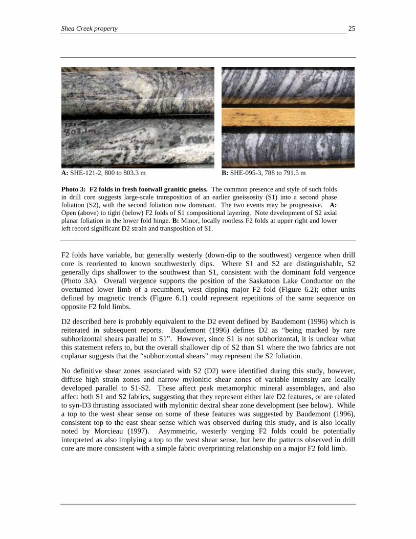
Shea Creek property 25
A: SHE-121-2, 800 to 803.3 m B: SHE-095-3, 788 to 791.5 m Photo 3: F2 folds in fresh footwall granitic gneiss. The common presence and style of such folds in drill core suggests large-scale transposition of an earlier gneissosity (S1) into a second phase foliation (S2), with the second foliation now dominant. The two events may be progressive. A: Open (above) to tight (below) F2 folds of S1 compositional layering. Note development of S2 axial planar foliation in the lower fold hinge. B: Minor, locally rootless F2 folds at upper right and lower left record significant D2 strain and transposition of S1. F2 folds have variable, but generally westerly (down-dip to the southwest) vergence when drill core is reoriented to known southwesterly dips. Where S1 and S2 are distinguishable, S2 generally dips shallower to the southwest than S1, consistent with the dominant fold vergence (Photo 3A). Overall vergence supports the position of the Saskatoon Lake Conductor on the overturned lower limb of a recumbent, west dipping major F2 fold (Figure 6.2); other units defined by magnetic trends (Figure 6.1) could represent repetitions of the same sequence on opposite F2 fold limbs. D2 described here is probably equivalent to the D2 event defined by Baudemont (1996) which is reiterated in subsequent reports. Baudemont (1996) defines D2 as “being marked by rare subhorizontal shears parallel to S1”. However, since S1 is not subhorizontal, it is unclear what this statement refers to, but the overall shallower dip of S2 than S1 where the two fabrics are not coplanar suggests that the “subhorizontal shears” may represent the S2 foliation. No definitive shear zones associated with S2 (D2) were identified during this study, however, diffuse high strain zones and narrow mylonitic shear zones of variable intensity are locally developed parallel to S1-S2. These affect peak metamorphic mineral assemblages, and also affect both S1 and S2 fabrics, suggesting that they represent either late D2 features, or are related to syn-D3 thrusting associated with mylonitic dextral shear zone development (see below). While a top to the west shear sense on some of these features was suggested by Baudemont (1996), consistent top to the east shear sense which was observed during this study, and is also locally noted by Morcieau (1997). Asymmetric, westerly verging F2 folds could be potentially interpreted as also implying a top to the west shear sense, but here the patterns observed in drill core are more consistent with a simple fabric overprinting relationship on a major F2 fold limb.

Shea Creek property 26
6.4 Retrograde shear zones and later brittle faults: controls to uranium mineralization Several varieties of both pre- and post Athabasca faults are superimposed on the earlier penetrative metamorphic fabrics and mineral assemblages. These include a series of both oblique slip mylonites and potentially associated concordant thrusts, as well as later brittle phases of faulting. These are reviewed in detail here since their distribution, style and architecture have fundamental influence on the distribution of uranium mineralization. 6.4.1 Steeply dipping D3 mylonites and offsets of the Saskatoon Lake conductor S1 and S2 are overprinted on the northern Shea Creek property by a series of dominantly northeast-trending, steeply dipping narrow mylonitic shear zones. This event, consistently coded D3 by all previous workers (e.g. Baudemont, 1996, Moriceau, 1997; Flotte, 2006) and in this study, is probably coeval with the development of the Beatty River Shear zone and other major northeast-trending regional shear zones during dextral transpression overlapping Hudsonian orogenesis that is discussed in Section 6.1. As mentioned above, subsidiary northeast trending dextral shear zones to the Beatty River Shear zone that are defined by offsets of magnetic patterns extend into the area of the Anne, Kianna and Colette Deposits (Figure 6.1). West-northwest trending offsets and magnetic lineaments also suggest the potential presence of a conjugate set of sinistral, west-northwest trending shear zones, as interpreted in northern parts of the property by Moriceau (1997) on the Douglas property north of the Colette Deposit. In drill core on the northern Shea Creek property and southern Douglas property (see Moriceau, 1997), narrow mylonitic shear zones have been intersected in many drill holes within basement rocks. These comprise ductile mylonites and ultramylonites that are well laminated, very fine-grained and often colour banded (Photos 4A, B). The mylonites vary from sets of narrow slip surfaces to larger mylonitic shear zones that are up to several meters wide, which often have sharp boundaries. The largest mylonites observed in core are locally surrounded by a broader damage zone where minor, parallel chlorite-coated slip surfaces, local incipient chlorite-matrix lithified cataclastic breccias and high fracture density extend outward several meters from the core shear zone. They are generally discordant to gneissosity, and where core re-orientation is possible using the known orientation of dominant foliation (Photo 4A), often trend northeast with steep dips, consistent with the Beatty River and associated shear zones. Other orientations with variable kinematics are also suggested but no consistent patterns were defined during the fieldwork. Oblique internal fabrics, including mylonitic foliation developed obliquely to shear zones margins (C-S geometry), shear bands, and asymmetric pressure shadows on porphyroclasts suggest that these structures accommodate right-lateral (dextral) shear sense with a variable vertical component, consistent with the offset on other known mylonitic shear zones in the area. Moriceau (1997) also reports sinistral–oblique kinematic indicators or steeply dipping, northwest-trending mylonites in the Colette area that are potentially conjugate, and subsidiary to, the northeast-trending mylonites. Preservation of biotite, but replacement of other higher grade metamorphic minerals such as garnet, and the occurrence of chlorite as matrix to local minor peripheral cataclastic breccias along some mylonites, suggest that these structures formed under greenschist grade conditions. These structures are retrograde in timing as they overprint peak metamorphic minerals, and both the S1 and S2 foliations. A pre-Athabasca timing is indicated on all of these structures since the mylonites do not penetrate into the overlying Athabasca sandstone, do not offset the unconformity, and are overprinted by paleoweathering clay alteration.

Shea Creek property 27
A: SHE-114-5, 960.6 m
B: SHE-122-1, 898.5-898.7 m
C: Top SHE-054, 719.5 m; bottom = SHE-61A, 779.3 m D: SHE-114-4, 901.8-903.2 m Photo 4: Mylonites in granitic and pelitic gneiss in the northern Shea Creek property. A: Ultramylonite (left) cuts across, and is in sharp contact with S1-S2 gneissosity in granitic gneiss (right). Core re-orientation on S1 assuming a typical moderate southwest dip suggests that this mylonite trends east-northeast with steep dips. This is one of a series of mylonites that are spatially related to the Kianna basement mineralization; this example lies just outside the alteration. B: Ultramylonite developed in granitic pegmatite. C: Narrow slip surfaces developed peripheral to larger mylonitic shear zones cut across gneissosity in granitic and pelitic gneiss. Even thin slip surfaces can have significant displacement, suggesting that displacement across 1-2 m wide ultramylonites here may be considerable, and consistent with the offset of the pelitic gneiss. In the lower photo, the slip surfaces are filled with a narrow quartz+/-chlorite shear vein. D: Sheeted quartz > chlorite extension veinlets in garnetiferous granitic gneiss. Core reorientation suggests north to northeast dips, consistent with measurements obtained in drill core. These veinlets are parallel to, and probably coeval with chlorite-coated extensional joints that form the dominant feature that have been measured in oriented drill core. As veins often occur within or are developed more abundantly peripheral to mylonites (e.g. in the Kianna area), and are locally affected by them, the veins and joints may represent extensional fractures formed in response to displacement on the mylonites. While mylonites are widespread in the northern Shea Creek property, they are not abundant, and most drill holes lack mylonite intercepts. However, their steeply dipping orientation is subparallel to most drill holes, so their frequency is probably underrepresented in drill core. Narrow mylonites were observed in multiple drill holes in the Kianna Deposit area, where they occur coincident with the intense area of basement alteration that is host to high grade uranium mineralization there, suggesting a possible pre-mineralization control (see Section 8). Other areas of mylonite development observed in drill core locally coincide with displacements of the pelitic gneiss unit between the Anne and Kianna Deposits.

Shea Creek property 28
Quartz +/- carbonate extension veins, many with prismatic quartz fill perpendicular to vein walls, are often spatially associated with mylonites, particularly in the Kianna area. Some veins fill minor mylonites, and displacement is accommodated across them. More than one set of quartz extension veins may be present, including a syn-mylonite and later syn-mineralization veining phase, as is discussed below. Core re-orientation on gneissosity suggests that the quartz veins are sheeted in parallel sets, and dip moderately to steeply to the northeast and north. Syn-mylonite quartz veins may reflect syn-kinematic extensional and shear hosted veining formed in response to hydraulic fracturing during mylonite displacement. 6.4.2 Offsets of the Saskatoon Lake conductor Note that the patterns of fault distribution and their significance interpreted here for the northern Shea Creek property are based on work and interpretations by the authors, and differ from those interpreted by AREVA. Drilling indicates that the pelitic gneiss unit which is host to the Saskatoon Lake Conductor is offset by multiple, northeast-trending faults (e.g. Robbins et al., 1998; Baudemont and Lorilleaux, 1998). With the high drilling density in the northern Shea Creek property, these offsets are easily recognizable by modeling of the pelitic gneiss unit. Principal faults based on these offsets interpreted here are illustrated in Figure 6.2, and named for the purposes of this report by the closest local 50 meter spaced gridline where they pass across the pelitic unit. Based on this, at least five significant apparent right-lateral (dextral), northeast-trending faults /shear zones with between approximately 40 and 110 meters of displacement are apparent or interpreted between the northwestern end of the Anne Deposit and the Colette Deposit, the 7000N, 7250N, 7600N, 8450N and 8800N faults (Figure 6.2). The largest apparent offset is on the 8450N fault, which is suggested by a large step in the trace of the pelitic gneiss unit between the Colette South and 58B areas. Approximately 90 and 115 meters of displacement are suggested, depending on how the contact is interpreted. In addition to these northeast-trending faults, deflections in the pelitic gneiss and locally in the Athabasca unconformity suggest the presence of low displacement east-west to east-northeast trending faults with minor sinistral (left lateral) apparent offsets. These are less well defined than the northeasterly trending set, but may be economically significant as they lie in areas of some of the best mineralization in all three deposits, including a fault zone termed here the Kianna Fault (Figure 6.2), which has been recognized by Flotte (2006) and Koning et al. (2008) to be coincident with, and probably control, basement mineralization at the Kianna Deposit. This, and other potential faults associated with mineralization are further discussed in the sections below. The lack of offset of the sub-Athabasca unconformity on many of these faults suggests that the fault displacements are largely pre-Athabasca in timing. Steeply dipping east- to northeast-trending mylonites were observed in the basement along the projected trace of several of these structures, particularly the 7000N and 8800N faults, as multiple narrow mylonites associated with quartz veins along the Kianna Fault, and along the faults in the northern Colette Deposit. The potential conjugate northeast-trending dextral – east-west to northwest-trending sinistral shear sense of the two fault orientations, implied pre-Athabasca timing, and local physical presence of suitably oriented mylonites along the trace of these offsets suggests that the offset is related to displacements on pre-Athabasca mylonites, which in turn are associated with the regional D3 event and Beatty River shear zone. Later remobilization of these structures appears to be an important local control on uranium mineralization in the northern Shea Creek property.

Shea Creek property
29
The mylonites in the northern Shea Creek property may be coeval with much thicker, concordant mylonitic shear zones which are reported to be developed at Cluff Lake near contacts between the Peter River and Earl River gneiss. These predate, but are spatially related to basement mineralization there (e.g. Dominique-Peter: Baudemont and Fedorowich, 1996), and further convey the favorable association between earlier mylonitic shear zones and later uranium mineralization. If the Shea Creek mylonites are coeval with the Beatty River shear zone, then these structures may represent mylonitic thrusts that were coeval with the northeast-trending shear zones, but which are now re-oriented in the Cluff Lake structure. Like possible regional F2 folds, such thrusts could also result in imbrication of the metamorphic sequence regionally, and potentially contribute to the parallel map patterns suggested by magnetic data in Figure 6.1. 6.4.3 Graphitic shear zones and gneissosity parallel concordant mylonites: possible syn-D3 structures In addition to the discordant mylonites, which cut across the metamorphic stratigraphy, concordant to semi-concordant, moderate to shallow west-southwest dipping shear zones and local mylonites are developed along the lower portions of the pelitic unit in graphitic gneiss and locally in other parts of the sequence. These overprint S1 and S2 foliations, and are probably coeval with the more steeply dipping mylonites described above. The shear zones near the base of the pelitic gneiss unit and overprinting later faulting have been collectively termed the “R3” fault (Baudemont and Lorilleaux, 1998). Where not completely overprinted by later brittle faulting and clay alteration, the shear zones in the graphitic gneiss unit are semi-brittle in style. Foliation is defined by alignment of phyllosilicate minerals and foliated compositional bands (Photo 5B), and by widespread development of pressure solution fabrics, which are in part defined by stylolitic graphitic surfaces (Photo 5A). Narrow lenses of lithified carbonaceous cataclastic breccia are often present along shear zone slip surfaces (Photo 5C). The combination of foliation development, pressure solution, and brecciation through cataclasis defines an overall semi-brittle style. Diffuse shear zones of this style appear to have affected much of the lower, graphitic portions of the pelitic package along the R3 trace prior to overprinting by later brittle faulting (see below). However, within this, more intense discrete shear zones are typically narrow, and 5-50 cm thick. Higher in the pelitic package in more quartzofeldspathic garnet gneiss, shear zones may also be present, but in the absence of graphite to aid in pressure solution processes, may have more pervasively ductile, mylonitic texture. The presence of oblique internal foliation, which dips more steeply than the shear zone slip surfaces (Photos 5B, C), synthetic shear bands, and asymmetric pressure shadows on entrained wallrock fragments and mineral aggregates, record a dominantly reverse (southwest side up thrusting) shear sense on these structures where determinable by re-orientation. The shear sense suggests an overall west-southwest-east-northeast direction of shortening which is compatible with the inferred offset on the D3 mylonitic shear zones, suggesting displacement on the two differently oriented shear zones may have been coeval. Regionally, many of the major mylonite zones terminate in, or have associated marginal thrust faults, comparable with these relationships.
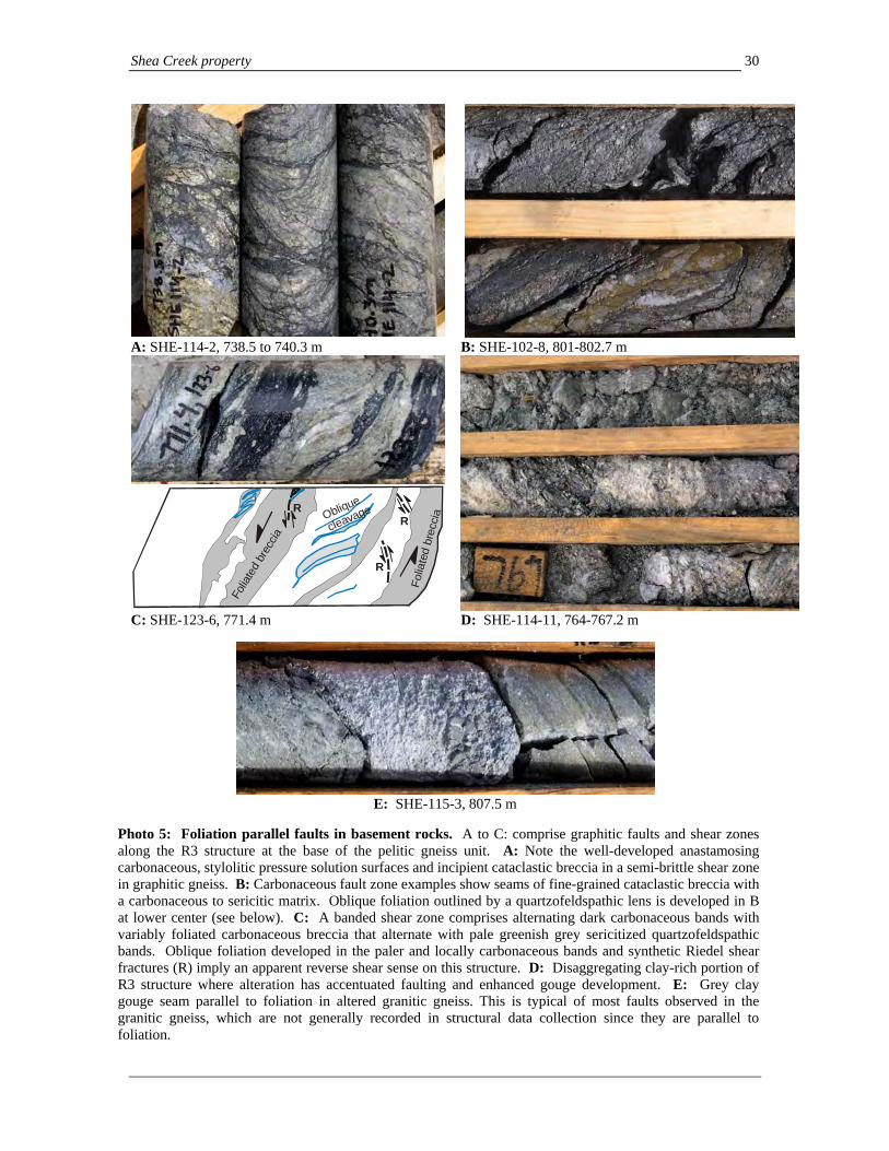
Shea Creek property 30
A: SHE-114-2, 738.5 to 740.3 m B: SHE-102-8, 801-802.7 m
R
Oblique
cleavageR
R
Folia
ted
brec
cia
Folia
ted
brec
cia
C: SHE-123-6, 771.4 m D: SHE-114-11, 764-767.2 m
E: SHE-115-3, 807.5 m
Photo 5: Foliation parallel faults in basement rocks. A to C: comprise graphitic faults and shear zones along the R3 structure at the base of the pelitic gneiss unit. A: Note the well-developed anastamosing carbonaceous, stylolitic pressure solution surfaces and incipient cataclastic breccia in a semi-brittle shear zone in graphitic gneiss. B: Carbonaceous fault zone examples show seams of fine-grained cataclastic breccia with a carbonaceous to sericitic matrix. Oblique foliation outlined by a quartzofeldspathic lens is developed in B at lower center (see below). C: A banded shear zone comprises alternating dark carbonaceous bands with variably foliated carbonaceous breccia that alternate with pale greenish grey sericitized quartzofeldspathic bands. Oblique foliation developed in the paler and locally carbonaceous bands and synthetic Riedel shear fractures (R) imply an apparent reverse shear sense on this structure. D: Disaggregating clay-rich portion of R3 structure where alteration has accentuated faulting and enhanced gouge development. E: Grey clay gouge seam parallel to foliation in altered granitic gneiss. This is typical of most faults observed in the granitic gneiss, which are not generally recorded in structural data collection since they are parallel to foliation.

Shea Creek property 31
6.4.4 Late faulting: post-Athabasca tectonic activity The position and significance of post-Athabasca faulting effects is most clearly determinable by offsets of the sub-Athabasca unconformity, since any significant offsets with even a small vertical component will cause topographic changes to the unconformity surface. In the northern Shea Creek property, the most significant post-Athabasca faulting effects, which offset the unconformity, occur where west-southwest dipping faults localized along the base of the pelitic unit (Saskatoon Lake Conductor) intersect the sub-Athabasca unconformity. This fault zone, comprising remobilized graphitic shear zone surfaces of the R3 fault and other parallel faults above, results in approximately several tens of meters of southwest side up reverse offset of the unconformity that is visible on unconformity elevation contour maps (Figure 6.4) and on cross sections through the deposits (see Figures 8.1 to 8.5). The offset is distributed over a plan width of 50 to 150 meters in which multiple minor offsets on different fault strands cumulatively accommodate the full displacement. Across this corridor, from hangingwall to the southwest, to footwall to the northeast, cumulative displacement measured by the total change in elevation of the unconformity ranges from approximately 20 to 50 meters. Greatest displacements are in the Kianna (35-50 meters) and Anne (approximately 35 meters) areas, and lower overall displacements are present in the Colette area (20-25 meters). As with other post-Athabasca faults in the Athabasca Basin, overall geometry of the distributed displacement is of an open, monoclinal fold of the unconformity surface, with tilting of sandstone bedding to shallow northeast dips above the distributed fault trace. In some areas of greatest displacement, small thrust wedges of basement several meters high emplace lenses of basement over basal portions of the Athabasca sandstone. This results locally in folding of the sandstone adjacent to or near the wedge in which the sandstone bedding may be tilted to steeply dipping or overturned. The basement thrust wedges are also locally emplaced over chlorite-matrix breccias which are associated with uranium mineralization. The thrust wedges, post-depositional tilting of the sandstone bedding above the broad fault trace, and similarity of thin basal conglomerate on both the southwest and northeast sides of the fault indicate that the change in unconformity elevation is post-Athabasca in timing and not related to pre-Athabasca paleotopography as is seen in other parts of the Athabasca Basin. In contrast, pre-Athabasca paleotopography would likely result in differences in the stratigraphy of the basal Athabasca sandstone on different sides of the unconformity elevation drop. The fault zones responsible for the displacement of the unconformity and basal sandstone represent dominantly brittle remobilization of shear zones and foliation surfaces in the pelitic gneiss unit, particularly along the R3 structure in graphite-rich portions near its base. In these areas, grey to green chlorite-clay and dark grey carbonaceous (graphitic) clay gouge seams exploit foliation and shear zone slip surfaces (Photo 5D). The brittle faulting is accompanied by clay alteration, which along with a broad damage zone of minor slip surfaces further accentuates the effects of the gouge seams, resulting in extensive areas of disaggregating, broken altered gneiss along lower portions of the pelitic gneiss unit. These generally thin downdip away from the unconformity in many areas, and below the effects of paleoweathering brittle fault surfaces may be more confined, although exceptions occur, and broader areas of clay alteration were observed around the R3 fault in the shaft pilot hole P08-01, well below the unconformity. Brittle faults developed parallel to foliation surfaces are also the most common fault orientation observed in the underlying Lower Felsic granitic gneiss to the pelitic gneiss unit. These faults are generally pale green grey clay gouge filled zones (Photo 5E) that vary from a few centimeters to more than one meter in width. They occur periodically beneath, and parallel to the R3 structure in

Shea Creek property 32
5865
00E
5870
00E
5860
00E
Figure 6.4: Northern Shea Creek property:
Contoured unconformity elevation in meters below sea level,
based on drilling data
-333.9
-346.7
-35 4.0
-363.0
-350.2
-360.7
-353.8
-353.7
-367.7-359.8
-36 6.2
-351.6
-347.2
-34 2.7
-338.3
-33 4.3
-334.4
-345.6
-347.7
-343.3
-33 1.8
-327.3
-335.3
-346.1-34 6.4
-343.9 -356.3
-355.5
-351.8
-355.4
-352.8
-325.5
-329.8
-337.2
-327.6
-35 0.0
-345.4
-372.3
-34 3.2
-34 3.5
-342.0
-34 2.4
-334.1-347.0
-343.8
-34 9.4
-34 7.2
-345.8
-347.3
-34 3.0
-355.0
-34 9.2
-353.8
-345.7
-349.5
-345.9
-360.4
-35 3.3
-357.8
-35 7.5
-356.5
-354.4-355.0
-354.7
-36 9.6
-361.4
-369.1
-361.3-36 1.7
-358.4
-37 0.5
-365.7
-369.5
-36 0.5
-367.5
-358.6
-367.1
-367.4
-370.9-368.3
-357.9
-354.0
-353.7
-35 9.1
-365.6
-351.3
-370.9
-349.4-345.5
-342.0
-35 7.3
-361.9
-361.1
-362.5
-367.8
-371.4
-352.0
-352.0
-357.4
-353.1
-33 0.0
-334.3
-339.2
-335.4
-338.6
-325.9
-340.3
-340.2
-335.4
-333.1
-32 6.4
-344.1
-355.8
-355.2
-35 3.3
-351.4
-335.0
-337.1
-332.1
-33 6.8-356.6 -360.0
-347.3-348.0
-369.7
-348.3
-356.7
-344.4
-345.9
-326.7
-322.6
-339.0-338.0
-316.4
-34 9.2
-345.2
-341.4
-34 4.3
-33 5.3
-330.0
-335.5
-36 0.8-350.1
-332.6
-348.0
-333.7
-335.8
-335.5-334.0
-334.0
-33 4.7-333.4-336.4
-337.9
-334.0
-335.5
-33 5.6
-339.0
-334.9
-341.6
-346.2-342.5
-334.6
-331.9
-331.3
-333.1
-338.1-334.8
-344.5-338.2
-352.6
-34 0.7
-341.0
-34 9.9
-345.0-341.8
-343.7-342.2
-351.0
-341.2
-349.2
-345.3
-36 1.5
-357.2-35 7.0
-360.9
-370.0-365.7
-331.8
-336.7
-330.2
-334.3
-341.2
-336.1
-336.7-337.8
-34 1.3
-354.9
-355.4
-349.6
-339.0
-338.0
-33 7.0
-340.7
-346.7
-349.2
-342.6-341.7
-354.7
-354.7
-344.3
-345.9
-355.6
-365.4
-363.4
-351.4
-350.0-341.1
-355.7
-355.0
-34 4.5
-349.7
-363.8
-371.7
-37 6.9
-365.9
-36 7.4
-370.1-369.1
-370.6
-374.6
-319.9
-336.2
-327.2
-343.0
-353.5
-348.6
-35 3.5
-352.7
-337.3
-342.8
-33 2.0-33 5.0
-359.2
-35 5.2
-352.6-353.2
-359.9
-355.1
-34 9.6
-349.5
-343.1
-356.2
-359.1
-357.6
-360.8
-35 1.0
-350.8
-364.4
-362.0
-355.9
-342.6
-370.4
-36 6.9
-369.7
5875
00E
6455000N
6455500N
6456000N
6456500N
6457000N
5860
00E
-365-360-355-350
-370-370
-370-365
-365
-345
-340
-370
-370
-365
-360-355
-350
-370
-345
-330
-325
-365
-360
-355-350-345
-340
-335
-355
-350
-345-340
-335-330
-360
< -325m
-325 to -330m
-330 to -335m
-335 to -340m
-340 to -345m
-345 to -350m
-350 to -355m
-355 to -360m
> -365m
-360 to -365m
LEGEND
N
E
S
W
ColetteDeposit
ColetteSouth
58B area
Kianna Deposit
AnneDeposit
WNW trending deflection

Shea Creek property
33
the Kianna and Anne areas, but are not abundant. Faults discordant to foliation were rarely observed, and where present showed no consistent orientation when re-oriented on the foliation. These patterns are consistent with the paucity of discordant faults in the AREVA structural database (see Section 6.4.6 below, and Figure 6.8C). Below the effects of paleoweathering, outside of areas of clay alteration related to uranium mineralization and faulting along the pelitic gneiss, much of the granitic gneiss sequence is fresh and unfaulted. Areas of intense clay alteration developed locally in basement rocks beneath the Kianna Deposit are described further in Section 8.2 below. Where intense, the clay alteration can resemble broad areas of faulting; they also may accentuate and form areas of pervasive clay between, or containing spaced fault surfaces. Discrete, measurable fault planes are often absent in these areas, however. Where basement hosted brittle faults pass upward into the overlying Athabasca sandstone, and where their extent is not obscured by alteration and brecciation associated with uranium mineralization, they may persist for several meters as discrete structures before dissipating into fractured sandstone. In the sandstone, they will sometimes steepen into narrow fault surfaces, or have splays which exploit bedding planes. The overall upward dissipation of faults in the sandstone column is consistent with progressive accommodation of fault displacement by folding higher in the sandstone column, as is seen in many fault systems associated with uranium deposits in the eastern Athabsaca Basin. Termination points of some of these faults may locally correlate with the position of development of perched mineralization in the South Colette, Kianna and Anne Deposits, possibly due to enhanced structural permeability related to dissipation of the faults into more distributed fracture zones. In some cases, however, faults project into 3 to 50 cm wide zones of foliated cataclasite in which pressure solution seams defined by chlorite or pyrite in the basal sandstone column wrap around lenses and fragments of sandstone (Photo 6). The cataclasites are defined by anastamosing zones of tectonic grain size reduction which contain the pressure solution seams (Photos 6A, B). Riedel shear fractures are commonly well developed, and where it is possible to reorient them on sandstone bedding planes, suggest a top to the northeast shear sense consistent with the reverse faulting episode. The foliated cataclasites not only affect the sandstone, but also affect chlorite-matrix solution breccias which are spatially associated with uranium mineralization at the base of the sandstone column (Photo 6B). Locally such faults also exploit, and follow along the unconformity surface for several tens of meters from where the principal faults enter the sandstone column. The overprinting of syn-mineralization breccias by these narrow foliated cataclasites, and their structural style imply that a) reverse faulting was active during mineralization, and b) the pressure solution fabrics, and their definition in part by pyrite and chlorite, imply that reduced, Fe-Mg bearing, and probably basement-derived syn-tectonic fluid flow occurred along these structures, potentially during the primary mineralization episode. Also implied is that some of the pressure solution fabrics seen along the R3 and related structures may also be post-Athabasca in timing, and with their extensive development of pressure solution fabrics imply dissolution of quartz, feldspars and others minerals, provide a syn-tectonic source of dissolved material which may have been channeled up to the unconformity during mineralization – the potential reduced basement fluid of mineralization. As with graphitic faults in other unconformity deposits, graphite along these areas of faulting is often converted to non-reflective dull black carbonaceous matter, consistent with low temperature alteration assemblages associated with the pressure solution fabrics. The pressure solution fabrics record extensive volume loss in many shear zones, upgrading the graphite-carbonaceous content, and resulting in widespread dissolution of minerals along cleavage planes.

Shea Creek property 34
A: SHE-114-3, 749.2 to 749.4 m B: SHE-114-4, 715.7 m
C: SHE-130-1, 720.5 m
Photo 6: Semi-brittle faulting affecting basal sandstone and chlorite matrix breccias above the Athabasca unconformity. A: Shallow dipping shear zone in sandstone with thin bands of foliated cataclasite defined by darker stylolitic chlorite-pyrite at left and center. In the right part of the photo, well-developed synthetic Riedel shear fractures (at shallow core axis angle) link the slip surfaces at left to the base of the shear zone out of the picture to the right. B: Chlorite-matrix breccia with silicified sandstone fragments (intact at left) is overprinted at center and right by a foliated semi-brittle shear zone, which contains anastamosing foliation that wraps around fragments. Sandstone fragments are reduced in grain size and often flattened into lenses that are surrounded by pressure solution seams. C: Undulating stylolitic foliation and diffuse cataclasites are superimposed on a chlorite-matrix breccia in sandstone. Chlorite occurs with some pyrite in the stylolites. 6.4.5 Patterns of post-Athabasca fault activity In combination with fault locations identified and traced in drill core, and modeling of the pelitic gneiss and other marker units, fault locations and post-Athabasca displacements which may influence uranium mineralization can be identified on unconformity elevation contour maps which illustrate offsets of the unconformity surface (Figure 6.4). In addition to the north-northwest trending reverse (southwest side up) offset of the unconformity associated with the main unit R3 structure along the pelitic gneiss unit, several discordant fault offsets of the unconformity surface are also apparent, as is shown on Figure 6.4. These are marked as breaks in the topographic contours associated with the R3 fault and imply that either the R3 fault is offset, or that the R3 and the discordant faults are interacting, with the R3 slip surfaces stepping as they join with, and then reappear across the discordant faults. Note that the patterns of fault distribution and their significance interpreted here for the northern Shea Creek property are based on the work and interpretations of the authors, and differ from those interpreted by AREVA.

Shea Creek property 35
The largest deflections which imply post-Athabasca offset associated with discordant faults are in the Colette area. These include:
a) In northwestern parts of the Colette Deposit, the unconformity contours deflect
substantially to the left along an east-northeast trend which corresponds with the position of the offset interpreted as the Colette Fault. Since paleoweathered, pre-Athabasca mylonites are present in drill core in this area along the trace of this feature (e.g. drill hole SHE-081, immediately below the unconformity), this would imply that the defection implies post-Athabasca remobilization of a pre-Athabasca mylonite zone.
b) At the southeastern end of the Colette Deposit, between Colette and Colette South, a
significant right-handed, northeast trending deflection in the unconformity contours corresponds with the position of the interpreted 8800N dextral fault. However, the change in the position of the unconformity contours along the R3 parallel trend across this is greater than the apparent offset of the pelitic unit (Figure 6.5). This implies that the southwest dipping thrust faults which include the R3 fault may have changed position from the Colette South area, where they correspond with the position of the pelitic gneiss, to the main Colette area, where the unconformity contours suggest at least some of the southwest dipping faults which offset the unconformity have moved to the northeast into the underlying granitic gneiss (Figure 6.5, inset). This also corresponds with a change in the position of unconformity mineralization from Colette South, where it lies above the pelitic gneiss unit, to the eastern parts of the main Colette area, where it occurs to the northeast of the pelitic unit (Figure 6.5). The distribution of uranium mineralization is thus more closely tied to the position of the offset of the unconformity (i.e. the intersection of the faults with the unconformity) than to the position of the pelitic gneiss.
In addition to these, additional deflections of the unconformity surface that are oblique to the R3/pelitic gneiss fault trend include a wedge-like step up bounded by northeast and east-west trending contour deflections in the northern Anne Deposit that is coincident with the some of the best developed mineralization there (Figure 6.6), and similar but more minor deflections with northeast to east-northeast trends in the Kianna and South Kianna areas (Figure 6.6), which also correspond with better developed mineralization. More subtle, local bends to more east-west trends of the contour traces also occur in the south Anne, 58B, and Colette South areas, which also commonly correspond with changes in the strike of the underlying pelitic gneiss, and often with areas of better developed mineralization. These may reflect the position of additional east-west to east-northeast trending faults, which based on the deflections, may accommodate a component of post-Athabasca sinistral displacement (see Kianna Fault discussion below; Figure 6.6).
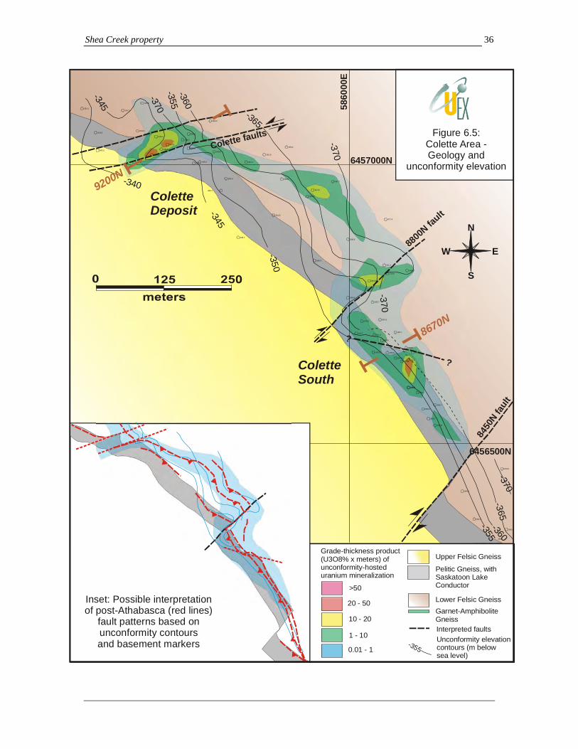
Shea Creek property 36
6456500N
6457000N
5860
00E
ColetteDeposit
ColetteSouth
8450
N faul
t
8800
N fault
Colette faults
N
E
S
W
-346.7
-354.0
-363.0
-350.2
-360.7
-353.8
-353.7
-367.7-359.8
-366.2
-351.6
>50
20 - 50
10 - 20
1 - 10
0.01 - 1
Interpreted faults
Upper Felsic Gneiss
Pelitic Gneiss, withSaskatoon Lake Conductor
Lower Felsic GneissGarnet-Amphibolite Gneiss
Figure 6.5:Colette Area -Geology and
unconformity elevation
-343.2
-343.5
-342.0
-342.4
-334.1-347.0
-343.8
-349.4
-347.2
-345.8
-347.3
-343.0
-355.0
-349.2
-353.8
-345.7
-349.5
-345.9
-360.4
-353.3
-357.8-357.5
-356.5
-354.4-355.0
-354.7
-369.6
-361.4
-369.1
-361.3-361.7
-358.4
-370.5
-365.7
-369.5
-360.5
-367.5
-358.6
-367.1
-367.4
-370.9-368.3
-354.0
-359.1
-365.6
-351.3
-370.9
-361.9
-361.1
-362.5
-367.8
-371.4
-360
-355-370
-365
-345
-340-370
-370
-365
-360
-355
-350
-370
-345
Grade-thickness product(U3O8% x meters) of unconformity-hosted uranium mineralization
Inset: Possible interpretationof post-Athabasca (red lines)
fault patterns based onunconformity contoursand basement markers Unconformity elevation
contours (m below sea level)
-355
?
? 8670N
9200N

Shea Creek property 37
6455500N
6455000N
5865
00E
5870
00E
AnneDeposit
7600N fault
7250N fault
7000N
fault
Kianna fault
N
E
S
W
-347.2
-342.7
-338.3
-334.3
-334.4
-345.6
-347.7
-343.3
-331.8
-327.3
-335.3
-346.1-346.4
-343.9 -356.3
-355.5
-351.8
-355.4
-352.8
-325.5
-329.8
-337.2
-327.6
-350.0
>50
20 - 50
10 - 20
1 - 10
0.01 - 1
LEGEND
Interpreted faults
Upper Felsic Gneiss
Pelitic Gneiss, withSaskatoon Lake ConductorLower Felsic Gneiss
Lithologies
Garnet-Amphibolite Gneiss
-352.0
-352.0
-357.4
-353.1
-330.0
-334.3
-339.2
-335.4
-338.6
-325.9
-340.3
-340.2
-335.4
-333.1
-326.4
-344.1
-355.8
-355.2
-353.3
-351.4
-335.0
-337.1
-332.1
-336.8-356.6 -360.0
-347.3-348.0
-369.7
-348.3
-356.7
-344.4
-345.9
-326.7
-322.6
-339.0-338.0
-316.4
-349.2
-345.2
-341.4
-344.3
-335.3
-330.0
-335.5
-360.8-350.1
-332.6
-348.0
-333.7
-335.8
-335.5-334.0
-334.0
-334.7
-333.4-336.4
-337.9
-334.0
-335.5
-335.6
-339.0
-334.9
-341.6
-346.2
-342.5
-334.6
-331.9
-331.3
-333.1
-338.1-334.8
-344.5-338.2
-352.6
-340.7
-341.0
-349.9
-345.0-341.8
-343.7-342.2
-351.0
-341.2
-349.2
-345.3
-361.5
-357.2-357.0
-360.9
-370.0-365.7
-331.8
-336.7
-330.2
-334.3
-341.2
-336.1
-336.7-337.8
-341.3
-354.9
-355.4
-349.6
-339.0
-338.0
-337.0
-340.7
-346.7
-349.2
-342.6-341.7
-354.7
-354.7
-344.3
-345.9
-355.6
-365.4
-363.4
-351.4
-350.0-341.1
-355.7
-355.0
-344.5
-349.7
-363.8
-371.7
-376.9
-365.9
-367.4
-370.1-369.1
-370.6
-374.6
-336.2
-327.2
-343.0
-353.5
-348.6
-353.5
-352.7
-337.3
-342.8
-332.0-335.0
-359.2
-355.2
-352.6-353.2
-359.9
-355.1
-349.6
-349.5
-343.1
-356.2
-359.1
-357.6
-360.8
-351.0
-350.8
-364.4
-362.0
-330
-325
-365
-360
-355-350-345
-340
-335
-355
-350
-345-340
-335-330
-360
Grade-thickness product(U3O8% x meters) of unconformity-hosted uranium mineralization
Deflections incontours - possible faults
Figure 6.6:Kianna and Anne areas -
Geology and unconformity elevation
Deflections incontours - possible faults
? Projection to unconformity of main body of Kianna basement mineralization at -450 RL
Unconformity elevationcontours (m below sea level)
-355
??
?
?
6750N
6875N
Kianna Deposit
Basement clay zone
Kianna south
Basement clay zone
SHE-38A
Kia
nna
sect
ion
P08-01
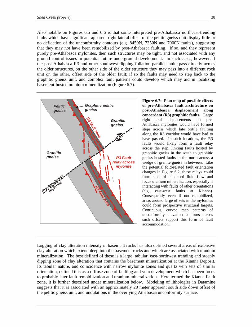
Shea Creek property 38
Also notable on Figures 6.5 and 6.6 is that some interpreted pre-Athabasca northeast-trending faults which have significant apparent right lateral offset of the pelitic gneiss unit display little or no deflection of the unconformity contours (e.g. 8450N, 7250N and 7000N faults), suggesting that they may not have been remobilized by post-Athabasca faulting. If so, and they represent purely pre-Athabasca mylonites, then such structures may be tight, and not associated with any ground control issues in potential future underground development. In such cases, however, if the post-Athabasca R3 and other southwest dipping foliation parallel faults pass directly across the older structures, on the other side of the older structure they may pass into a different rock unit on the other, offset side of the older fault; if so the faults may need to step back to the graphitic gneiss unit, and complex fault patterns could develop which may aid in localizing basement-hosted uranium mineralization (Figure 6.7).
Peliticgneiss
Graphitic peliticgneiss
Graniticgneiss
Graniticgneiss
Pre-Athabasca
mylonite R3 fault zone
R3 fault zoneR3 Fault
relay acrossmylonite
Figure 6.7: Plan map of possible effects of pre-Athabasca fault architecture on post-Athabasca displacement along concordant (R3) graphitic faults. Large right-lateral displacements on pre-Athabasca mylonites would have formed steps across which late brittle faulting along the R3 corridor would have had to have passed. In such locations, the R3 faults would likely form a fault relay across the step, linking faults hosted by graphitic gneiss in the south to graphitic gneiss hosted faults in the north across a wedge of granite gneiss in between. Like the potential fold-related fault orientation changes in Figure 6.2, these relays could form sites of enhanced fluid flow and focus uranium mineralization, especially if interacting with faults of other orientations (e.g. east-west faults at Kianna). Consequently even if not remobilized, areas around large offsets in the mylonites could form prospective structural targets. Continuous, curved map patterns of unconformity elevation contours across such offsets support this form of fault accommodation.
Logging of clay alteration intensity in basement rocks has also defined several areas of extensive clay alteration which extend deep into the basement rocks and which are associated with uranium mineralization. The best defined of these is a large, tabular, east-northwest trending and steeply dipping zone of clay alteration that contains the basement mineralization at the Kianna Deposit. Its tabular nature, and coincidence with narrow mylonite zones and quartz vein sets of similar orientation, defined this as a diffuse zone of faulting and vein development which has been focus to probably later fault remobilization and uranium mineralization. Here termed the Kianna Fault zone, it is further described under mineralization below. Modeling of lithologies in Datamine suggests that it is associated with an approximately 20 meter apparent south side down offset of the pelitic gneiss unit, and undulations in the overlying Athabasca unconformity surface.
Shea Creek property 39
6.4.6 Veins and fractures: implications from oriented drill core Since 2004, AREVA has obtained oriented drill core from many holes in the Kianna, Anne and south Colette areas with use of core orientation tools such as EZ-Mark and ACE. Data measured from drill core include dominant foliation, faults, veins and fractures, the latter which based on coding can also include additional types of veins. Most of the data is from the Kianna area. Plots shown in Figure 6.8 illustrate equal area projections of poles to selected structural features from this set. Note the clustering of foliation in the Anne and Kianna areas with moderate/shallow southwestern dips, consistent with the geology defined by drilling. This consistency provides a quality control validation of the oriented core measurements from the drill holes, and confidence that measurements of other structural features from the same intervals are representative as well. Other structural features presented here include discordant brittle faults, quartz veins, and pitchblende-bearing veins and fractures, and fractures undifferentiated. Some data originally coded as fractures has been subdivided into various vein types based on notes accompanying the measurements which define the fractures as filled with quartz, pyrite, dravite, carbonate and other minerals. Equal area plots of quartz vein and undifferentiated fracture data are shown in Figures 6.8D and 6.8E. While there is much scatter, broad dominant clusters occur in both plots which indicate overall moderate to steep north- to northeast dips and east-west to northwest strikes. A subsidiary set trends east-west with steep southerly dips. The quartz vein orientations are consistent with that observed in drill core during the core logging review. The consistent patterns of fractures with the quartz veins suggest that the fractures are mainly extensional joints formed during the quartz veining event at Kianna, which is consistent with their overall nature observed in drill core in areas where the structural data was collected. Fault orientations from different drilling areas between Anne and Colette are combined on Figure 6.8C since data are sparse. The AREVA fault data has been collected from faults which are not parallel to foliation; faults in the R3 structure and others in the granitic gneiss sequence are consequently not in the data set. Apart from very broad southwesterly dips to data in the northeast quadrant, poles to faults in Figure 6.8C show no consistent orientations in this small data set. Future data collection should also record the common foliation-parallel faults. Poles to veinlets and fractures containing uranium mineralization (pitchblende) from the Kianna, south Kianna and Anne areas are illustrated in Figure 6.8F. Note the cluster of east-west to east-northeast trending, dominantly moderate north dipping veinlets, which overlap with the contouring peak of the quartz vein set in Figure 6.8E. The overall strike of vein orientations are similar to the east-west to east-northeast trending fault trends suggested by offsets of the sub-Athabasca unconformity (e.g. Kianna Fault), although the dips are shallower. The morphology of uranium mineralization is further discussed in section 8. Following page: Figure 6.8: Equal area projection of poles to selected structural data measured from oriented drill core in the northern Shea Creek property. Consistent southwest dipping dominant foliation in the Kianna and Anne areas acts as a quality control check to validate other measurements. Note the under-representation of foliation parallel faults in plot C, which are common in drill core, but which are recorded only as foliation. Quartz extension veins in E are largely parallel to joints in C, suggesting that the joints are mainly extensional. Pitchblende-bearing fractures and veinlets in F dip moderately north-northwest in the dominant cluster.

Shea Creek property 40
NEqual Area
(Schmidt)
Axial N = 1805
NEqual Area(Schmidt)
Axial N = 205 A: Kianna foliation. Contouring peak of 56 053 corresponds with orientation of 143/34
B: Anne foliation. Contouring peak of 56 037 corresponds with orientation of 127/34
NEqual Area(Schmidt)
Axial N = 43
NEqual Area(Schmidt)
Axial N = 1563 C: All faults in the database, from Anne, Kianna and Colette. There are insufficient data to identify patterns
D: “Fractures”, from the Kianna area (largely joints). The plots exclude data in E and F, below. Note general north to northeast dip.
NEqual Area(Schmidt)
Axial N = 518
NEqual Area(Schmidt)
Axial N = 96 E: Quartz veins, Kianna. Moderate north to northeast dips predominate. Similar to joints in D.
F: Pitchblende veinlets, Anne Kianna and Colette. Contouring peak of 48 171 corresponds with 261/42 orientation.
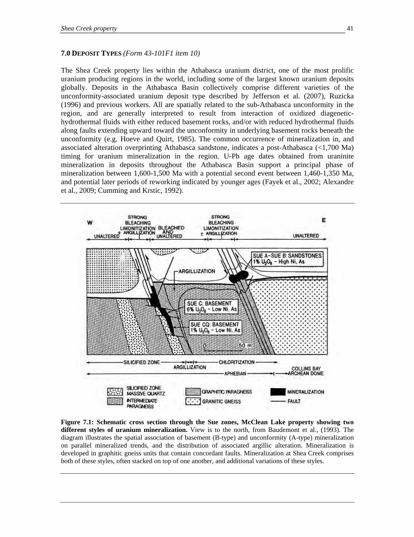
Shea Creek property 41
7.0 DEPOSIT TYPES (Form 43-101F1 item 10) The Shea Creek property lies within the Athabasca uranium district, one of the most prolific uranium producing regions in the world, including some of the largest known uranium deposits globally. Deposits in the Athabasca Basin collectively comprise different varieties of the unconformity-associated uranium deposit type described by Jefferson et al. (2007), Ruzicka (1996) and previous workers. All are spatially related to the sub-Athabasca unconformity in the region, and are generally interpreted to result from interaction of oxidized diagenetic-hydrothermal fluids with either reduced basement rocks, and/or with reduced hydrothermal fluids along faults extending upward toward the unconformity in underlying basement rocks beneath the unconformity (e.g. Hoeve and Quirt, 1985). The common occurrence of mineralization in, and associated alteration overprinting Athabasca sandstone, indicates a post-Athabasca (<1,700 Ma) timing for uranium mineralization in the region. U-Pb age dates obtained from uraninite mineralization in deposits throughout the Athabasca Basin support a principal phase of mineralization between 1,600-1,500 Ma with a potential second event between 1,460-1,350 Ma, and potential later periods of reworking indicated by younger ages (Fayek et al., 2002; Alexandre et al., 2009; Cumming and Krstic, 1992).
Figure 7.1: Schematic cross section through the Sue zones, McClean Lake property showing two different styles of uranium mineralization. View is to the north, from Baudemont et al., (1993). The diagram illustrates the spatial association of basement (B-type) and unconformity (A-type) mineralization on parallel mineralized trends, and the distribution of associated argillic alteration. Mineralization is developed in graphitic gneiss units that contain concordant faults. Mineralization at Shea Creek comprises both of these styles, often stacked on top of one another, and additional variations of these styles.
Shea Creek property 42
Uranium deposits in the Athabasca Basin area form three different, although commonly spatially related, styles of unconformity type uranium deposits (e.g. Figure 7.1):
A. Deposits developed at, or just above, the Athabasca unconformity in Athabasca sandstone where basement hosted, often graphitic faults and shear zones intersect the sub-Athabasca unconformity. These deposits occur in basal Athabasca sandstone in the footwall wedge to graphite-bearing shear zones and faults that are graphitic gneiss overthrust on Athabasca sandstone (e.g. Collins Bay A, B and D-zones; Key Lake), or in gradational drops/humps in the unconformity above graphite-rich lithologies and faults (e.g. Cigar Lake, Cluff Lake A zone; Midwest Lake; Sue A/B, West Bear, McClean Lake, Maybelle River; Figure 7.1). Mineralization occurs in pods and disseminations in Mg-chlorite-clay-hematite alteration, locally overprinting spatially associated breccias and zones of intense clay alteration that sit directly above mineralization in sandstone (Figure 7.2). Common structural sites include bends and steps in fault systems, or 5-20 m humps in the unconformity that may reflect the interaction of graphitic shear zones with faults of different orientations. Deposits of this style are often characterized by assemblages of Ni and Ni-Co arsenides and sulpharsenides that accompany uranium mineralization. Locally, this style of mineralization is associated with perched mineralization which occurs in veinlets and lenses up to several tens of meters above the unconformity within alteration plumes that extend upward into the sandstone column.
B. Basement-hosted deposits within or surrounding fault zones in predominantly non-calcareous gneiss. These deposits are exemplified by Eagle Point, Millennium, Dominique-Peter and Sue C. Eagle Point, Dominique Peter, and Sue C are composed of veins, disseminations and pods that link, or overprint shear zones and faults, often in or near graphitic-bearing gneiss. Veins frequently occur in extensional fractures that may link individual faults (Sue CQ, Figure 7.1; Telephone zone), or occur as sets of replacement veins which extend obliquely off faults in enveloping zones of clay alteration (e.g. Eagle Point, Dominique-Peter). Unlike deposits of type A above, these deposits generally lack arsenide and sulpharsenide minerals in mineralized zones, although basement hosted mineralization at Shea Creek may be an exception to this pattern (see below). Mineralization is composed of discrete pitchblende veins, planar replacements of fine-grained nodular pitchblende + clays, or undulating pitchblende/uraninite-bearing redox fronts surrounding clay veins and faults. A variation on this deposit type occurs at UEX’s Raven and Horseshoe, where mineralization occurs in hematitic redox fronts and veins surrounding large, semi-tabular clay alteration zones that are cored by probable faults (Rhys et al., 2008). Horseshoe and Raven also differ from other basement deposits in the region in that they lack spatially associated graphitic gneiss units or carbonaceous fault zones.
C. Basement-hosted deposits associated with hydrothermal breccias in calcareous gneiss and calcsilicate adjacent to northeast-trending faults. The only example of an orebody of this type in the region is the Rabbit Lake Deposit in the eastern Athabasca Basin, although parts of the Dawn Lake Deposit and other prospects are of similar style, and the largest basement-hosted unconformity deposits in the Alligator River district of northern Australia are closely comparable. The Rabbit Lake Deposit occurs perched above the Rabbit Lake Fault at its intersection with the North-South Fault, which is part of the Dragon Lake Tabbernor-type fault system, illustrating the local importance of interaction of discordant and concordant faults in the localization of uranium mineralization. Mineralization occurs on the margins of a large hydrothermal, chlorite-matrix breccia body that affects dolomitic marble and adjacent lithologies, and that may have formed during dissolution collapse of the carbonate, forming a highly permeable zone (Rhys and Ross, 1999). High-grade mineralization is superimposed on the northeastern margins of the breccia and associated silicification/dravitization along the trace of the North-South Fault.

Shea Creek property 43
Both the “A” and “B” styles of mineralization are present at Shea Creek. Uranium deposits in the Athabasca region frequently occur in deposit clusters that comprise one or more deposit types. For example, four major uranium deposits, the Collins Bay zones (type A deposits) and the Eagle Point mine (type B), occur along a 5.5 km strike length of the Collins Bay Fault system on the Rabbit Lake property (Figure 6.1). Other deposit clusters include the Sue, McClean Lake, and Dawn Lake Deposits (Figure 6.1), where deposits occur in at least two parallel trends, along which deposits may be strung out along parallel faulted graphite-bearing or calc-silicate units and spaced 100-700 m apart. More locally, the Cluff Lake deposits which lie only 13 to 16 km to the north of the Shea Creek deposits also show similar patterns, although primary relationships between deposits are disrupted by the effects of the Carswell Structure. Here, classic unconformity hosted (A type) mineralization at the Cluff Lake D zone is spatially associated with nearby basement hosted deposits such as Dominique-Peter (Koning and Robbins, 2006; Baudemont and Fedorowich, 1996). The spatial coincidence of unconformity and basement-hosted deposits emphasizes the importance of testing both the unconformity and basement rocks where mineralization has only been historically discovered at the unconformity. Often where unconformity-hosted and basement mineralization are spatially associated, the basement mineralization forms the larger deposit in the group (e.g. Sue, Dawn Lake, Eagle Point/Collins Bay zones, Cluff Lake). In other deposits, exemplified by Key Lake, dominant unconformity hosted mineralization may extend downward along faults in the basement, forming “roots” to the unconformity-hosted mineralization. Deposits of all the styles described above are associated with, and generally enveloped by, intense zones of argillic alteration that are composed predominantly of illite, chlorite and kaolinite. The influence of alteration extends over a far greater area than the dimensions of the deposits themselves, and consequently the tracking of alteration distribution, mineral zonation and associated lithogeochemical changes is an important tool in vectoring exploration (Sopuck et al., 1983; Quirt, 2002). In the Athabasca sandstone, alteration plumes may extend hundreds of meters above the unconformity-hosted uranium deposits, while in basement rocks alteration is generally more restricted to the vicinity of associated faults and veins. Mineralization frequently occurs at redox fronts marked by zones of hematization, and a change from sulphide to oxide accessory mineral assemblages (Figure 7.2). Uranium deposits in the area are generally associated with reverse fault zones that are localized within, or cross graphitic gneiss and carbonate/calc-silicate units, often overprinting pre-Athabasca, retrograde metamorphic shear zones. Post-Athabasca faulting associated with mineralization is generally low displacement, accommodating meters to a few tens of meters of reverse displacement of the sub-Athabasca unconformity. Mineralization occurs in areas of enhanced structural permeability and/or low stress (dilatancy) along faults including fault junctions (e.g. Rabbit Lake), beneath brecciated sandstone under overthrust wedges (e.g. Collins Bay zones; McArthur River), at bends and en echelon steps in the faults (e.g. B-zone), and at dilational jogs (e.g. Eagle Point). These structural sites are in turn influenced at a broader scale by the occurrence of pre-Athabasca folds and basement shear zones, which control the distribution, continuity and morphology of the later faults. Mineralization is generally structurally late in the faulting history, and while basement-hosted mineralization is frequently localized along or adjacent to faults, both mineralization and its associated alteration may overprint fault rocks.

Shea Creek property 44
Grap
hite
Gne
iss
Paleoweathering profile
Athabasca Sandstone
Py
Hm
U
ClayAlteration, friable
sandstone
Non-graphitic gneiss
Chlorite - py
hem
Quartz veinlethalo below
mineralization
15-60 m
Diageneticfluids
U
Figure 7.2: Schematic cross section through a hypothetical unconformity-hosted deposit illustrating the diagenetic-hydrothermal model for deposit formation. Uranium mineralization (U) is developed at a stationary redox front where rising reduced fluids coming up graphite-gneiss hosted, low displacement reverse basement faults (pink arrows) react with circulating diagenetic-hydrothermal fluids in the overlying sandstone column (blue arrows). Chlorite-pyrite alteration envelops the mineralization in the basal sandstone column and is overlain by a hematite cap (hem), and then a broad zone of friable, locally clay altered sandstone which rises as a plume above the deposit. Secondary pyrite (Py) may occur high in the alteration zone. Note the sheeted quartz veins peripheral to the clay alteration in the basement rocks.
Shea Creek property 45
8.0 MINERALIZATION (Form 43-101F1 item 11) Uranium mineralization identified to date on the Shea Creek property lies in the northernmost portions of the property, comprising the Anne, Kianna and Colette Deposits and intervening mineralization in between them. These deposits occur along an approximately three kilometer strike length of the north-northwest trending pelitic gneiss unit that is host to the Saskatoon Lake Conductor (Figure 6.2). In other parts of the property, drilling is limited and widely spaced, but mineralization has locally been intersected two kilometers southeast of the Anne Deposit (e.g. Shea Creek area discovery hole SHE-002); elsewhere, much of the property has little or no drill testing. The discussion below is consequently focused on mineralization associated with the three deposits located in the northern Shea Creek property. Mineralization in these areas is typically developed at depths of 650 to 800 meters below the current surface, beneath a thick sequence of overlying Athabasca Group sandstone, at elevations of 330 to 550 m below sea level. 8.1 Uranium mineralization styles To date, drilling within the three kilometer corridor on the northern Shea Creek property has been focused in two areas in which semi-continuous mineralization has been traced at the unconformity: a) the Colette and south Colette area, over a 0.7 km strike length, and b) the Kianna to Anne deposit areas, over a 1.1 km strike length (Figure 6.2). The region in between the Kianna and Colette areas, termed the 58B area based on a mineralized intercept located there (Figure 6.2), has only been sparsely drilled and has high potential for discovery of additional mineralization. Significant drilling intercepts of the different mineralization styles are summarized in Section 10.5 below, and more comprehensively in Appendix 2. Within these mineralized domains in the northern Shea Creek property, three styles of mineralization are developed, based on relative position with respect to the Athabasca unconformity, and overall morphology. These three mineralization styles may be stacked on top of one another, which are illustrated in cross section in Figures 8.1 to 8.6. They comprise:
a) Unconformity-hosted mineralization (Photos 7,8): This is the most widespread style of mineralization identified to date on the northern Shea Creek property, and its outlines in plan view as currently defined are illustrated in Figures 6.2, 6.5 and 6.6. Unconformity style mineralization occurs as a shallow dipping sheet-like mineralized zone developed at the base of the Athabasca sandstone immediately above the sub-Athabasca unconformity (Figure 8.1; Photo 8), or straddling the unconformity and extending downward up to several meters into the underlying basement gneisses (Figure 8.3). It may also locally be contiguous with more extensive basement mineralization (Figure 8.2). The mineralization typically is elongate in plan view, occurring at the unconformity over a 40 to 150 m plan view lateral width along the trace of the northeastern margins of the pelitic gneiss unit where it intersects the unconformity and extending over parts of the footwall granitic gneiss (Figure 6.2). Unconformity-hosted mineralization in high grade areas may comprise massive, nodular or blebby pitchblende +/- coffinite +/- yellow U-silicates in a hematite-clay matrix (Photo 7) that grades between 5% and 35% U3O8 over intervals of several meters. In lower grade areas, unconformity-hosted mineralization may be disseminated in chlorite-clay-dravite alteration. The mineralization of all grades is often associated with, and occurs within, dissolution breccias in the basal sandstone, which have a chlorite-dravite matrix (see below), both as partial matrix replacement and as fragments. Unconformity-hosted

Shea Creek property 46
mineralization may be thickest and of highest grade in areas where basement and/or perched mineralization are developed vertically below or above it. These patterns are common in areas where steeply dipping northeast or east-west trending zones of faulting and clay alteration extend downward into basement rocks below.
A: SHE-050, 722-724 m: Kianna South area B: SHE-115-03, core from 744-746 m: Kianna Deposit
C: SHE-122-01, 717 m: Anne Deposit D: SHE-095-03, 721 m: Anne Deposit
Photo 7: Unconformity hosted mineralization textures. A: Center core row shows the top of a moderate grade intercept of unconformity mineralization (1.3% U3O8 over 2.7 m) with fine-grained disseminated and nodular pitchblende at the margin of the red hematite zone which is host to most of the mineralization (right). Sandstone at left is pyritic, reduced. B and C: Black primary pitchblende occurs as disseminated nodules and clots, irregularly shaped massive aggregates, and semi-pervasive replacements in a red-orange hematite-clay matrix which completely replaces the basal Athabasca sandstone. D: Very high grade interval of massive pitchblende from interval grading 58.1% U3O8 over 0.3 m. Note late carbonate-hematite veinlets cutting mineralization.

Shea Creek property 47
Photo 8: High grade unconformity uranium mineralization from drill hole SHE-115-03 in the Kianna Deposit illustrating textures and associated alteration. Core shown is from 717 to 753 m. In the top four core rows, bleached, pale grey Athabasca sandstone from which diagenetic hematite has been lost is underlain by a discrete zone of oxidized brick red hematite alteration of the sandstone (rows 7 to 10, upper center; “hematite halo”). This in turn is underlain by five rows between 734 and 742 m containing reduced, grey-green Fe-chlorite +/- pyrite altered sandstone which contains local disseminated and blebby pitchblende. The interval averages 3.36% U3O8. Note in the lowermost row of this interval, between 741.0 and 742.0 m, sandstone bedding is tilted at approximately 40 degrees to core axis. The chloritized sandstone is underlain by a zone of high grade pitchblende-hematite alteration between 742.0 and 746.3 m (dark black-reddish rows outlined in red on photo) which occurs at, and partly obscures, the unconformity with the underlying granitic gneiss unit. The interval grades 21.15% U3O8 over 4.3 m. Note inset detail of area outlined in blue on photo showing banded to blebby pitchblende-hematite, with pale green-grey pyrite (?marcasite) patches. The lower four rows below the mineralization are clay altered granitic gneiss basement rocks. The sequence of alteration is representative of that seen at Kianna and other deposits at Shea Creek, and is closely comparable to other unconformity uranium deposits in the Athabasca Basin, with mineralization occurring at a major change in redox conditions.

Shea Creek property 48
Legend
Athabasca sandstone
Pelitic gneiss
Garnet-amphibolite gneiss
Granitic gneiss
U3O8 >0.5%
U3O8 >0.05%
Clay alteration(>3 intensity)
400
W
350
W
300
W
-400 RL
-350 RL
-300 RL
-250 RL
SHE-
94-5
SHE-
94-6
SHE-99-1
SHE
-87
SHE
-94
SHE-
94-3
SHE-94-4 SH
E-99-1SHE
-99-
3 SHE-99-5
SHE
-87
SHE-
94-3
SHE-94 -4SH
E-94
-6
S HE
-9 9-3
SHE-99-5
650 m
650 m 650 m650 m650 m
650 m650 m
700
700700 700700700
700 m700700
750
750750 750
750750750
e0.418%17.70m
e0.294%6.30 m
e0.152%2.10 me0.124%
5.90 m
0.621%9.40m
5.740%2.80m
e1.878%13.30m 1.631%
2.50m
2.612%13.60m
e0.959%22.70m
0.494%10.60m
1.588%11.00m
0.215%4.00m
0.798%1.50m
e0.730%7.30m
11.607%6.00m
1.042%2.50m
2.132%0.60m
e0.192%2.90m
Lithologies
Mineralization
Alteration, faulting
Symbols
Unconformitysurface
Figure 8.1:Anne DepositSection 6750N
View north-northwestSee Fig. 6.6 for location
Perched
Unconformity
Basement
R3 Fault
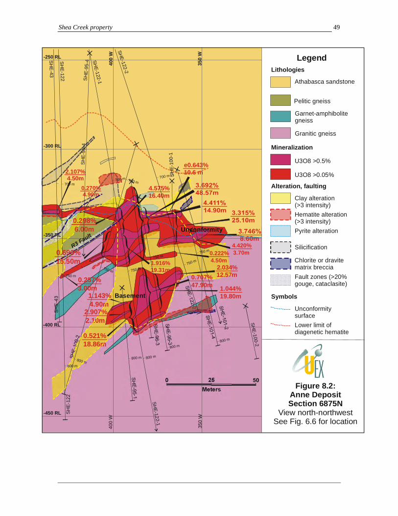
Shea Creek property 49
400
W
350
W
400
W
350
W
SHE-
100-
1
SHE
-100-2
SHE
-101-2
SHE-101-4
SHE-
109-
2
SH
E-12
2
SH
E-122-1
SHE-122-2
SHE
-43
SH
E-95-1
SHE
-95-3
SHE
- 95 -
4
SH
E-9 6-3
SH
E-9
5-4
SHE-122-2
SHE-122-1
SH
E-122
SH
E- 43
4.575%16.40m
2.107%4.50m
800 m
800 m800 m
800 m800 m
800 m
700 m700 m
700 m700 m
1.916%19.31m
0.521%18.86m
1.044%19.80m
0.222%4.50m
e0.643%10.6 m
750 m750 m750 m
750 m
750 m
750 m
0.257%3.00m
0.270%4.90m
1.143%4.90m
2.907%2.10m
0.707%47.90m
2.034%12.57m
4.420%3.70m
Legend
Athabasca sandstone
Pelitic gneiss
Garnet-amphibolite gneiss
Granitic gneiss
U3O8 >0.5%
U3O8 >0.05%
Clay alteration(>3 intensity)
Figure 8.2:Anne DepositSection 6875N
View north-northwestSee Fig. 6.6 for location
Lithologies
Mineralization
Alteration, faulting
Symbols
UnconformitysurfaceLower limit ofdiagenetic hematite
Hematite alteration(>3 intensity)Pyrite alteration
Silicification
Chlorite or dravite matrix brecciaFault zones (>20% gouge, cataclasite)
-450 RL
-400 RL
-350 RL
-300 RL
-250 RL
Unconformity
Basement
R3 Fault
0.298%6.00m
0.699%15.50m

Shea Creek property 50
400
W
7500
N
7600
N
-550 RL
-500 RL
-450 RL
-400 RL
-350 RL
-300 RL
650 m650 m 650 m650 m650 m
650 m650 m 650 m650 m
650 m650 m
650 m
650 m650 m
650 m
650 m
950
850
SH
E-114-1
SHE
-114
-11
SH
E-1
14-1
2
SH
E-114- 2
SH
E-1 14 -4
SH
E-1
14-5
SHE-
114-
6
SH
E-1
14- 7
SH
E- 1
14- 9
SH
E-1
15
SH
E-115- 10
SH
E-1
15-1
2
SH
E-1
15-1
7
SH
E-115-8
SH
E-115-9
SH
E-1
18-7
SH
E- 1
3 0
SHE-
130-
2S
HE
- 53
0.411%5.00m
SHE
-114
-13
750 m
750750 750750 750750750750
750750
750750
750750 750
750 m750750
750
750
800
800
750
800800800 800
800800800800
800
800800
800800800
800
800800
800
7.719%1.50m0.951%6.00m
0.325%8.50m
4.093%45.00m
0.213%4.00m0.278%3.00m
0.487%4.00m
850
900
850
900
850
900
850850
850
850 850
900
950
850
900
1.042%5.40m
700700
700700 700700700700 700
700
700700700
700
700
700700700
7000.316%4.50m
0.326%6.50m
SHE-102-11
1.100%8.50m
0.744%7.50m
SH
E-115-18
SH
E-1
30-1
SH
E-1
30-1
A
4.382%7.80m
0.080%8.00m0.329%
9.50m
0.095%5.50m
e20.72%10.20m0.305%
5.10m6.165%6.70m
SH
E-1
1 4- 1
0A
SHE
- 115-7
SHE-115-1
7600
N F
a ult
Legend
Athabasca sandstone
Pelitic gneiss
Garnet-amphibolite gneiss
Granitic gneiss
U3O8 >0.5%
U3O8 >0.05%
Clay alteration(>3 intensity)
Lithologies
Mineralization
Alteration, faulting
Symbols
UnconformitysurfaceLower limit ofdiagenetic hematite
Hematite alteration(>3 intensity)Pyrite alteration
High quartz vein densityChlorite alterationin sandstoneFault zones (>20% gouge, cataclasite)and associated friablealteration
SHE -114-17
Perched
Unconformity
Basem
ent
Prop
osed
drill
hol
e
Mylonite intercept(some off section)
??
NorthSouth
R3 Faults
Hematitic breccia
Potential new basement zone
Figure 8.3: Kianna Deposit, north south vertical cross section, looking west. See Figure 6.6 for location
Shea Creek property 51
b) Basement-hosted mineralization (Photos 9 to 11):
This is the second most extensive style of mineralization developed in the northern Shea Creek property. Basement-hosted mineralization at Shea Creek is developed mainly in the footwall granitic gneiss unit (Lower Felsic Gneiss) for up to 200 meters below the sub-Athabasca unconformity, and vertically below the unconformity-hosted mineralization (Figures 8.2 to 8.5). Some minor mineralization also occurs in the pelitic gneiss unit, often as lenses following southwest dipping fault planes. Basement-hosted mineralization is variable in style and morphology, and is associated with areas of intense white to pale green clay-chlorite alteration of the basement gneiss. Two dominant styles of basement mineralization are apparent in the Anne, Kianna and Colette areas:
Concordant style basement mineralization: In the southern parts of the Anne Deposit (Figure 8.1) and the Colette South area (Figure 8.4), basement mineralization forms dominantly shallow to moderate west-southwest lenticular zones that are parallel or sub-parallel to gneissosity in the granitic gneiss (Photo 9C; 10A to C). These zones locally follow fault surfaces or lithologic units. On several cross sections in both the Anne and Kianna areas, the garnet-amphibolite gneiss unit (metabasite) is preferentially mineralized, with areas of higher grade (see >0.5% U3O8 outlines on Figure 8.2) within mineralized zones occurring along the projection of, and replacing, this unit. Concordant mineralization may splay off the unconformity-hosted mineralization, as at south Anne (Figure 8.1), or occur separated from the unconformity locally in stacked foliation parallel lenses (Figure 8.4).
Discordant style basement mineralization: More complex zones of basement mineralization occur in the Kianna Deposit and northern parts of the Anne Deposit, where mineralization overall is defined as steeply dipping, easterly trending mineralized zones (Figures 8.2, 8.3), which are particularly well developed at Kianna. This style is discordant overall, and cuts steeply across the metamorphic sequence. However, it may be made up internally of several stacked higher grade subzones that are concordant and parallel to the southwest-dipping gneissosity (Figures 8.2 and 8.3).
Mineralization patterns suggest that a complete gradation in style occurs between concordant and discordant types of basement mineralization. Mineralization in these different types comprises textural varieties which include:
a) disseminated and nodular blebby replacement style pitchblende +/- hematite +/-U-silicates (Photo 9D) which may occur in irregular shaped zones locally with sinuous redox fronts (Photo 10D to F) but which at a larger scale may show southwest-dipping lithological control;
b) pervasively disseminated or massive lenses and veins of pitchblende that may be either concordant or discordant (Photo 9A to C); and
c) pitchblende in sets of pitchblende +/- quartz +/- hematite veinlets (Photo 11) that, based on oriented core, have dominantly east-west to east-northeast trends, and moderate to steep northerly dips (Figure 6.8F).
Interaction between the two mineralization styles, and the occurrence of splays of higher grade lenses of concordant mineralization off discordant mineralization apparent on many cross sections, suggests that oreshoots in discordant basement mineralization will plunge moderately to shallowly to the west-southwest – parallel to the intersection line of the discordant zones with gneissosity. Areas where discordant zones of mineralization are projected to cross garnet-amphibolite gneiss (“metabasite”) units are considered highly favorable for oreshoot development, as indicated by the preferential development of concordant mineralization along some of these units (Figure 8.2).
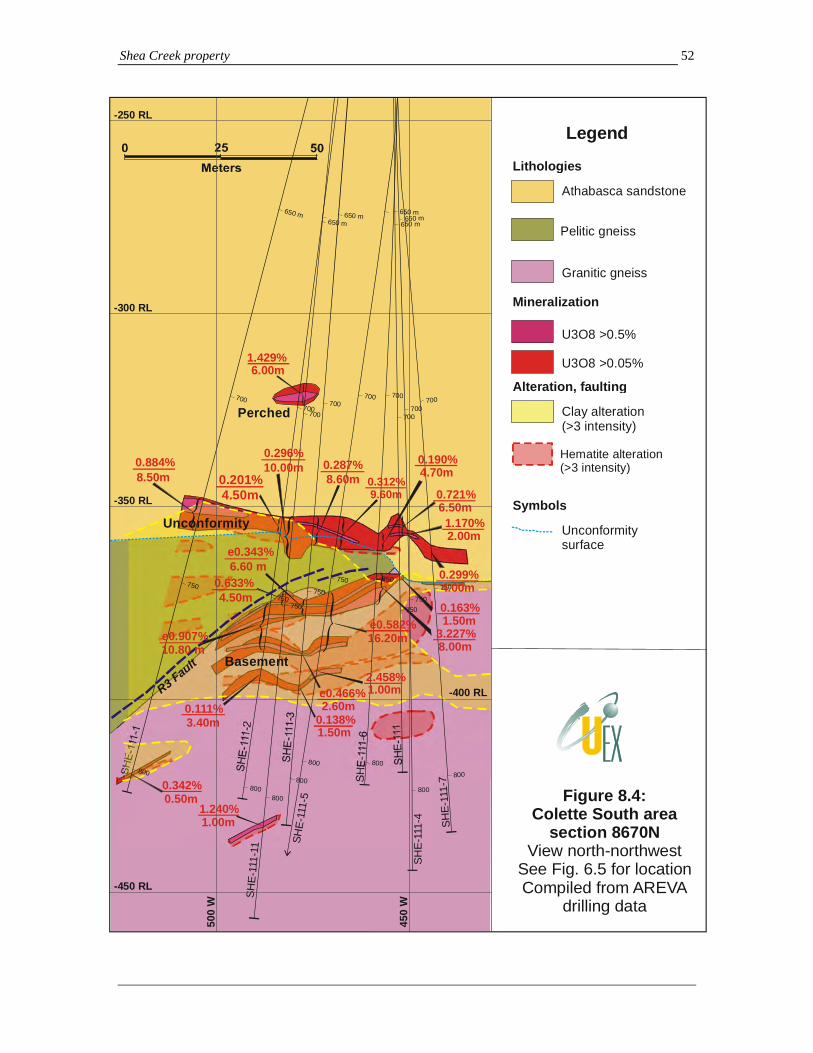
Shea Creek property 52
500
W
450
WSH
E-11
1
SHE-
111-
1
SHE-
111-
11SH
E-11
1-2
SHE-
111-
3
SHE-
111 -
6
SHE-
111-
5
SHE-
111-
4
SHE-
111-
7
1.240%1.00m
1.429%6.00m
0.884%8.50m
0.342%0.50m
650 m
700
750
650 m
700
750
800
650 m
700
750
800
700
750
800
650 m
700
750
800
650 m
700
750
800
700
750
800
650 m
700
750
800
700
750
800
0.201%4.50m
0.111%3.40m
0.296%10.00m
0.633%4.50m
0.287%8.60m
e0.343%6.60 m
0.138%1.50m
e0.466%2.60m
0.312%9.60m
e0.582%16.20m
2.458%1.00m
3.227%8.00m
0.190%4.70m
0.721%6.50m
0.163%1.50m
1.170%2.00m
Legend
Athabasca sandstone
Pelitic gneiss
Granitic gneiss
U3O8 >0.5%
U3O8 >0.05%
Clay alteration(>3 intensity)
Lithologies
Mineralization
Alteration, faulting
Symbols
Unconformitysurface
Figure 8.4:Colette South area
section 8670NView north-northwest
See Fig. 6.5 for locationCompiled from AREVA
drilling data
Unconformity
Basement
R3 Fault
e0.907%10.80 m
-450 RL
-400 RL
-350 RL
-300 RL
-250 RL
Perched
Hematite alteration(>3 intensity)
0.299%4.00m

Shea Creek property 53
SH
E-5
1
SH
E-5
2
SH
E-5
4
SH
E-5
9
SH
E-6
0
SH
E-7
8
SH
E-8
1
SHE-51
SHE-52
SHE-54
SHE-59
SHE-60
SHE-78
SHE-81
700
W
650
W
600
W
550
W
700
750
800
700
750
800
700
750
700
750
800
700
750
800
700
750
800
700
750
0.363%3.60m
1.122%11.00m1.028%
0.60m
4.099%6.60m
2.342%16.80m
1.578%1.60m
0.651%4.00m
1.133%6.10m
Athabasca sandstone
Pelitic gneiss
Granitic gneiss
U3O8 >0.5%
U3O8 >0.05%
Clay alteration
Lithologies Mineralization Alteration, symbols
Unconformitysurface
Hematite alteration
-450 RL
-400 RL
-350 RL
-300 RL
-250 RL
R3 Fault
Figure 8.5:Colette main area
section 9200NView north-northwest
See Fig. 6.5 for locationCompiled from AREVA drilling
data and some core review
Myl
onite
s -
?Col
ette
faul
ts

Shea Creek property 54
A: SHE-114-17, 881.9-885.3 m B: SHE-115-05, 794.5-795 m (top row)
C: SHE-115-11, 862.2-865.3 m D: SHE-115-06, 862.7-864.6 m
Photo 9: Kianna Deposit basement mineralization styles. A: Central row shows massive pitchblende-rich interval grading 20.0% U3O8 over 0.5 m in altered granitic gneiss. B: Irregular bands of semi-concordant high grade pitchblende-coffinite (?) in the top row occur in an interval grading 30.42% U3O8 over 0.5 m. Note clay-hematite altered granitic gneiss below. C: Central parts of a high grade basement intercept (5.38% U3O8 over 16.5 m), showing semi-concordant, but diffuse bands of pitchblende-hematite. This forms part of a shallow southwest dipping high grade, concordant lens (west-southwest plunging oreshoot) within the overall steeply dipping, northeast-trending Kianna basement zone. D: Irregular (“vermiform”) textured fine-grained nodular pitchblende-hematite replacement mineralization.
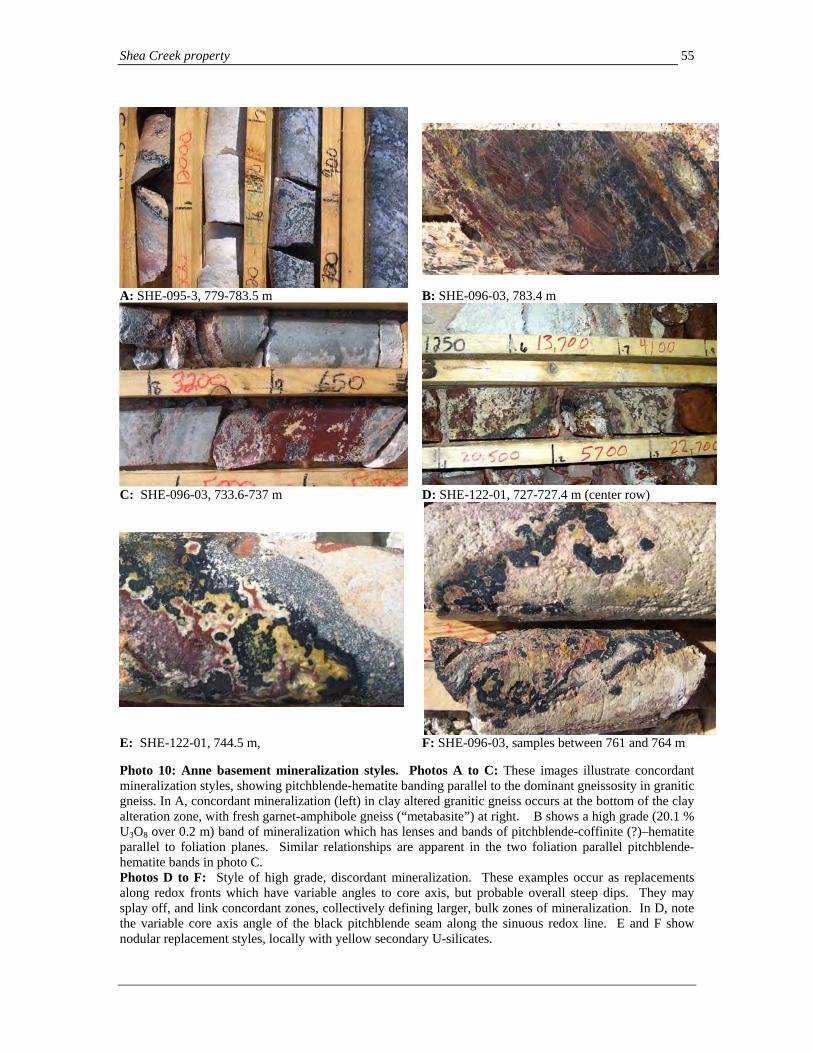
Shea Creek property 55
A: SHE-095-3, 779-783.5 m B: SHE-096-03, 783.4 m
C: SHE-096-03, 733.6-737 m D: SHE-122-01, 727-727.4 m (center row)
E: SHE-122-01, 744.5 m, F: SHE-096-03, samples between 761 and 764 m
Photo 10: Anne basement mineralization styles. Photos A to C: These images illustrate concordant mineralization styles, showing pitchblende-hematite banding parallel to the dominant gneissosity in granitic gneiss. In A, concordant mineralization (left) in clay altered granitic gneiss occurs at the bottom of the clay alteration zone, with fresh garnet-amphibole gneiss (“metabasite”) at right. B shows a high grade (20.1 % U3O8 over 0.2 m) band of mineralization which has lenses and bands of pitchblende-coffinite (?)–hematite parallel to foliation planes. Similar relationships are apparent in the two foliation parallel pitchblende-hematite bands in photo C. Photos D to F: Style of high grade, discordant mineralization. These examples occur as replacements along redox fronts which have variable angles to core axis, but probable overall steep dips. They may splay off, and link concordant zones, collectively defining larger, bulk zones of mineralization. In D, note the variable core axis angle of the black pitchblende seam along the sinuous redox line. E and F show nodular replacement styles, locally with yellow secondary U-silicates.

Shea Creek property 56
A: SHE-112-01, vein (above) at 767.6 m, Anne B: SHE-115-06, 875.8-877.6 m, Kianna Deposit
C: SHE-123-02, vein in lower row 786.7 m , Kianna South area
D: SHE-088, 759.6 m, Anne Deposit
Photo 11: Discordant vein style mineralization in basement rocks. All examples show discrete veins (A, C, D) or vein-like replacement zones (B) which cut across gneissosity at high angles in variably altered granitic gneiss. A: At upper right, a carbonate-pitchblende veinlet cuts almost 90 degrees across foliation, and is surrounded by an inner envelope of red-brown hematite, and at upper left, a thin black line marks a pitchblende-bearing redox front at the outer edge of the hematite envelope, which is parallel to the vein. B: In the lower core, a steeply dipping banded pitchblende (dark bands)-hematite-clay replacement vein at a shallow core axis angle cuts across the gneissosity at a high angle. The gneissosity is parallel to the fractures in the lower core row. C: Pitchblende-dravite-clay veinlets at shallow core axis angles cut across gneissosity. D: Discrete, steeply dipping pitchblende veinlet.
c) Perched mineralization (Photo 12): This mineralization style is developed above the unconformity in the Athabasca sandstone, occurring up to 60 meters above the unconformity. Volumetrically, this is the least extensive mineralization style, but it may have very high grades perched above the unconformity, such as in the Kianna area. Perched mineralization also varies in style, from shallow dipping lenses of disseminated, stringer or more massive mineralization that may be parallel to bedding in the Athabasca sandstone (Figure 8.4), to west-southwest-dipping zones that may follow faults and chloritic breccia bodies (Figure 8.1). The latter may extend off unconformity mineralization as a series of upward thinning lenses, or may occur as lenses separate from the unconformity mineralization that lie along minor faults and breccia zones which can sometimes be traced back to southwest dipping faults that follow gneissosity in the underlying pelitic and granitic gneiss units (e.g. south Anne Deposit; Figure 8.1). Controls on this mineralization style may consequently be related to the

Shea Creek property 57
dissipation upward of foliation faults into the overlying sandstone, and/or to more pervasive permeability-redox control, occurring at the mixing-interaction point between basement derived fluids along faults with oxidized basinal fluids.
A: Oblique view of core: black, mineralized interval is from 679 to 689 m, and has some core loss
B: Detail of high grade mineralization
Photo 12: High grade Kianna perched mineralization in drill hole SHE-114-5. A: Black high-grade pitchblende mineralization hosted by friable, clay altered Athabasca sandstone occurs at center. This interval grades 20.721% eU3O8 (composited with probe grade due to core loss). B: Detail of mineralization: black, massive pitchblende with interstitial red-brown hematite-clay. Petrographic studies (e.g. Pacquet and Reyx, 1995; numerous reports by Pacquet and Reyx in 1996-1999 assessment reports) suggest that pitchblende (botryoidal uraninite) is the dominant uranium-bearing mineral in all three mineralization settings. A common paragenetic sequence which is frequently apparent from this petrographic work comprises early pitchblende locally accompanied by brannerite, which are replaced by secondary pitchblende + coffinite +/- boltwoodite or other U-silicates. In addition to pyrite and/or marcasite, uranium mineralization is often accompanied by small quantities of nickel arsenide minerals (gersdorffite, nickeline, and rammelsbergite), chalcopyrite, and galena which may occur included in, rimming, or as grains spatially associated with pitchblende (Pacquet and Reyx, 1995). Although present, Ni-arsenides occur only in minor quantities in perched and unconformity mineralization (generally <1,000 ppm Ni in high grade areas at Anne and Kianna with U/Ni and U/As ratios of generally >100 in perched mineralization and >10 in unconformity mineralization). Ni-arsenides are more abundant in basement zones (U/Ni and U/As ratios of >3) within areas of mineralization grading >0.05% U3O8. Consequently, mineralization at Shea Creek is more similar to the monomineralic character seen in the eastern Athabasca basin than the Ni-arsenide association observed at Midwest Lake or Cigar Lake, where U/Ni ratios often exceed, or are close to 1:1. Review of the Shea Creek analytical database indicates that Ni and As concentrations are typically highest in basement mineralization. In contrast, the typical occurrence of Ni and As in highest concentrations within deposits in the eastern Athabasca Basin is developed at the unconformity.

Shea Creek property 58
8.2 Alteration associated with uranium mineralization The Shea Creek mineralization is associated with areas of clay alteration and sandstone desilicification locally above the mineralization, and peripheral silicification which collectively may be detectable through resistivity surveys. Alteration patterns are closely comparable to other unconformity-type uranium deposits in the Athabasca Basin. These alteration patterns and distribution provide important indicators to the position and distribution of uranium mineralization. Alteration above the unconformity: Unconformity and perched mineralization In the Athabasca sandstone, initial areas of alteration which lie tens, to locally hundreds of meters above uranium mineralization are marked by bleaching of the sandstone to cream-pale grey with loss of the regional purple-red diagenetic hematite that is normally present in the sandstone, and by elevated clay content in the sandstone column (Quirt, 2002). In the Kianna and Anne areas, the bleaching commonly continues downward toward the unconformity as linear north-northwest trending belts of alteration which occur above the unconformity hosted mineralization. This alteration, from top to bottom towards the unconformity, comprises:
(i) a zone of friable, disaggregated and fractured sandstone (sandstone dissolution), locally with interstitial clay development, in which sandstone cement and framework quartz are often corroded,
(ii) an oxidized “cap” of brick-red hematite in sandstone that is typically several meters thick, and usually in more competent rock than the overlying friable sandstone (Photo 8),
(iii) more component, reduced sandstone containing disseminated or blebby pyrite and/or marcasite and tinted grey-green with disseminated chlorite (Photos 8, 13A), which becomes increasingly brecciated and grades downward into,
(iv) areas of sandstone dissolution breccia which lie immediately above the unconformity, and comprise angular sandstone fragments in a matrix of chlorite-clay-dravite +/- pyrite. Variable quantities of uranium mineralization as matrix fill and fragments are often associated with the lower parts of the breccias, and more massive high grade unconformity mineralization, where developed, will form the bottom of this sequence immediately above the gneiss sequence below.
Partial or complete profiles of the sequence described above are commonly observed, and are generally best developed and most intense above the higher grade and more extensive areas of uranium mineralization. Silicification of the sandstone may also be developed laterally to, or above the mineralization, and in many cases the presence of silicified sandstone fragments in the areas of chlorite breccias indicate that the sandstone was silicified prior to brecciation (Pacquet and Reyx, 1995). Secondary clay mineral content in the lower sandstone column associated with these alteration types includes both illite and kaolinite, with a general paragenetic sequence which commences with an early, widespread phase of illite alteration that is partially to totally overprinted by kaolinite, dravite and locally smectite and carbonates (Pacquet and Reyx, 1995; and reports by Pacquet and Reyx in 1996-1999 assessment reports). A late generation of illite is also noted locally. Late siderite and dolomite veinlets are locally present, and may cut across uranium mineralization (Photo 7D). Alteration patterns are similar in areas containing perched mineralization, with the perched zones locally inserted into the same sequence as described above below a locally developed hematite halo, and underlain by pyritic reduced assemblages. Pyrite may occur as discrete areas with
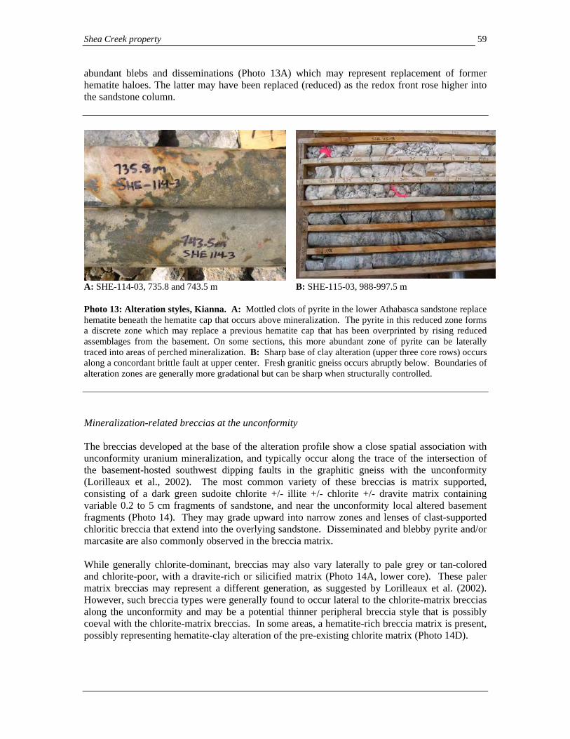
Shea Creek property 59
abundant blebs and disseminations (Photo 13A) which may represent replacement of former hematite haloes. The latter may have been replaced (reduced) as the redox front rose higher into the sandstone column.
A: SHE-114-03, 735.8 and 743.5 m B: SHE-115-03, 988-997.5 m Photo 13: Alteration styles, Kianna. A: Mottled clots of pyrite in the lower Athabasca sandstone replace hematite beneath the hematite cap that occurs above mineralization. The pyrite in this reduced zone forms a discrete zone which may replace a previous hematite cap that has been overprinted by rising reduced assemblages from the basement. On some sections, this more abundant zone of pyrite can be laterally traced into areas of perched mineralization. B: Sharp base of clay alteration (upper three core rows) occurs along a concordant brittle fault at upper center. Fresh granitic gneiss occurs abruptly below. Boundaries of alteration zones are generally more gradational but can be sharp when structurally controlled. Mineralization-related breccias at the unconformity The breccias developed at the base of the alteration profile show a close spatial association with unconformity uranium mineralization, and typically occur along the trace of the intersection of the basement-hosted southwest dipping faults in the graphitic gneiss with the unconformity (Lorilleaux et al., 2002). The most common variety of these breccias is matrix supported, consisting of a dark green sudoite chlorite +/- illite +/- chlorite +/- dravite matrix containing variable 0.2 to 5 cm fragments of sandstone, and near the unconformity local altered basement fragments (Photo 14). They may grade upward into narrow zones and lenses of clast-supported chloritic breccia that extend into the overlying sandstone. Disseminated and blebby pyrite and/or marcasite are also commonly observed in the breccia matrix. While generally chlorite-dominant, breccias may also vary laterally to pale grey or tan-colored and chlorite-poor, with a dravite-rich or silicified matrix (Photo 14A, lower core). These paler matrix breccias may represent a different generation, as suggested by Lorilleaux et al. (2002). However, such breccia types were generally found to occur lateral to the chlorite-matrix breccias along the unconformity and may be a potential thinner peripheral breccia style that is possibly coeval with the chlorite-matrix breccias. In some areas, a hematite-rich breccia matrix is present, possibly representing hematite-clay alteration of the pre-existing chlorite matrix (Photo 14D).
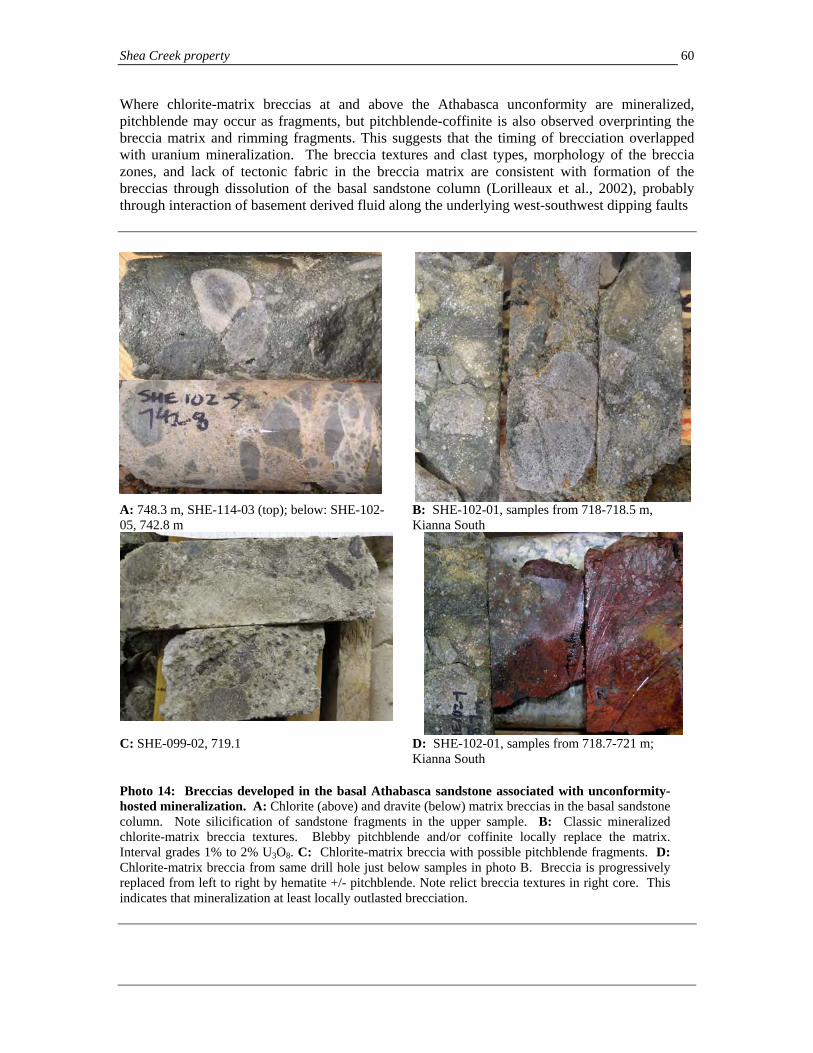
Shea Creek property 60
Where chlorite-matrix breccias at and above the Athabasca unconformity are mineralized, pitchblende may occur as fragments, but pitchblende-coffinite is also observed overprinting the breccia matrix and rimming fragments. This suggests that the timing of brecciation overlapped with uranium mineralization. The breccia textures and clast types, morphology of the breccia zones, and lack of tectonic fabric in the breccia matrix are consistent with formation of the breccias through dissolution of the basal sandstone column (Lorilleaux et al., 2002), probably through interaction of basement derived fluid along the underlying west-southwest dipping faults
A: 748.3 m, SHE-114-03 (top); below: SHE-102-05, 742.8 m
B: SHE-102-01, samples from 718-718.5 m, Kianna South
C: SHE-099-02, 719.1 D: SHE-102-01, samples from 718.7-721 m; Kianna South
Photo 14: Breccias developed in the basal Athabasca sandstone associated with unconformity-hosted mineralization. A: Chlorite (above) and dravite (below) matrix breccias in the basal sandstone column. Note silicification of sandstone fragments in the upper sample. B: Classic mineralized chlorite-matrix breccia textures. Blebby pitchblende and/or coffinite locally replace the matrix. Interval grades 1% to 2% U3O8. C: Chlorite-matrix breccia with possible pitchblende fragments. D: Chlorite-matrix breccia from same drill hole just below samples in photo B. Breccia is progressively replaced from left to right by hematite +/- pitchblende. Note relict breccia textures in right core. This indicates that mineralization at least locally outlasted brecciation.

Shea Creek property 61
in the basement rocks with basinal fluids in the Athabasca sandstone. As discussed in section 6.4.4, the presence of foliated cataclasites with pressure solution fault fabrics that extend into the breccias as extensions of the southwest dipping faults in the underlying pelitic gneiss unit indicate that tectonic activity, and syntectonic fluid flow continued after breccia formation. Overall patterns show an early illite-dominant alteration event in and around the unconformity which may have overlapped with silicification of the basal sandstone column, followed by various pulses of reduced basement fluid which rose to various levels in the lower sandstone column. These basement fluids were associated with the introduction of Fe-Mg-K-Al and B bearing chlorite, illite, kaolinite, dravite and pyrite-marcasite assemblages, with deposition of uranium mineralization at the interface with oxidized hematite-bearing assemblages above. Alteration in basement rocks: guides and controls to mineralization distribution Vertically zoned red to green zone pre-mineralization paleoweathering alteration, which affects basement rocks for up to several tens of meters below the unconformity, represents the earliest phases of clay alteration which affect basement rocks in the Shea Creek area. Beneath unconformity mineralization, this paleoweathering profile is hydrothermally overprinted by cream to pale green clay-chlorite alteration which contains varying quantities of sudoite chlorite, illite, kaolinite and dravite, which often show the same early illite to later kaolinite paragenesis observed in the sandstone (Pacquet and Reyx, 1995). Clay alteration can be tracked in basement rocks qualitatively by coding its relative intensity, from fresh rocks, through increasing visually estimated intensity of initial alteration of ferro-magnesium minerals, feldspars, and quartz, with increasing overall friability. Alteration extends deeper and is most intense around basement-hosted mineralization, forming broad zones which may extend for more than 200 meters below the unconformity. In these areas, alteration is locally intense, altering the gneissic basement rocks to variably friable, cream colored clay-rich zones over intervals of tens, to locally >100 meters, where even quartz in the gneiss may be corroded or replaced by clay. Friable clay-rich zones can be difficult to distinguish from faults, but in most cases primary relict texture is preserved and intact, indicating that large portions of the alteration are not affected by any significant translational displacement. Faults comprising white to greenish clay gouge however, are present in clay altered zones, and locally bound some intense areas of alteration. These faults are generally parallel to gneissosity where observed, although discordant faults are also locally present that may play an important role in localizing mineralization. Modeling of the basement alteration provides a valuable tool for assessing the potential distribution, and nearby position of uranium mineralization. In the Kianna area, modeling of areas of highest visually estimated alteration defines a steeply dipping, approximately east-west trending zone of intense white to green clay alteration. In plan view this clay zone is 100 to 170 meters wide, which extends to the limits of drilling approximately 200 meters below the Athabasca unconformity, and is open to the east and west (Figures 6.6, 8.3). This alteration zone contains the basement-hosted mineralization at Kianna, and corresponds with the apparent left lateral offset of the pelitic gneiss unit, suggesting that the clay zone is localized along a distributed fault zone. As discussed in Section 6, this clay zone corresponds with the orientation and location of several narrow mylonitic shear zones which predate, and are overprinted by the clay alteration, suggesting it may be localized along an older fault zone. The zone as a whole has been termed the Kianna Fault. Similar, but less pronounced deflection of the pelitic gneiss unit with associated basement alteration is apparent in the area of well developed basement mineralization in the northwestern Anne Deposit, suggesting that the alteration and mineralization there may also be controlled by steeply dipping faulting which is oblique to the gneiss sequence.
Shea Creek property 62
Basement clay alteration also occurs in an east-northeast trending zone in the Kianna South area (Figure 6.6), where it lies below some of the better developed mineralization at the unconformity, and may extend westward to join alteration intersected in drill hole P08-01, which contains a narrow zone of mineralization at the unconformity. Chlorite-clay alteration often extends down concordant faults in the pelitic gneiss unit, particularly in the area of the graphitic gneiss hosted R3 faulting near its base. The alteration results in coalescing friable zones of green chlorite-clay alteration which join between fault surfaces, and are most extensive above basement mineralization in the Kianna area (Figure 8.4). Much of the pelitic unit well below the Athabasca unconformity is affected by weak to moderate intensity chlorite alteration even where still competent, resulting in loss of primary metamorphic minerals. This may be in part related to a combination of:
a) syntectonic alteration associated with active reverse faulting along these faults which generated the pressure solution fabrics,
b) pre-Athabasca paleoweathering alteration preferentially following earlier faults into the basement, and
c) syn-mineralization penetration of fluids down the faults from the Athabasca sandstone above. Similar alteration patterns occur around faults associated with mineralization in uranium deposits in the eastern Athabasca Basin.
Modeling of these clay altered zones using clay intensities defined during drill core logging may aid in definition of ground conditions for underground development planning. Relationships of quartz veins, mylonites and alteration at Kianna Veinlets and veins of different mineralogy which were recorded by density per meter during the core logging program show consistent distribution patterns. Areas of highest quartz +/- pyrite vein and veinlet density occur above, and locally peripheral to, the basement mineralization at Kianna (Figure 8.3). In addition, quartz-dravite and dravite veins are generally most abundant where developed close to mineralization and more proximal than the quartz +/- pyrite veinlets. Carbonate and quartz-carbonate veinlets are most concentrated in basement rocks just below unconformity mineralization. These patterns are common in other basement-hosted uranium deposits – Eagle Point, Rabbit Lake, Horseshoe and McArthur River have peripheral sets of quartz veins for example, and sets of quartz veinlets commonly occur beneath unconformity-hosted uranium mineralization as well (Figure 7.2). The patterns suggest that these vein types form part of the alteration envelopes to the Kianna mineralization, and areas of higher vein density can be used as guides of proximity to mineralized zones. Dominant vein orientations of quartz in Figure 6.8E overlap with orientations of uranium-bearing veinlets and fractures in Figure 6.8F, although the quartz veins also vary to more northwesterly trends. Syn-mineralization quartz veins may reflect redistribution of quartz dissolved in oxidized areas of clay alteration zones outward for re-deposition with pyrite in extensional veinlets in reduced areas on the margins of the alteration zones; telescoping onto the veins of the clay alteration is also evident later in some areas. A close timing between at least some of the quartz veining and uranium mineralization is indicated by the occurrence of fine-grained prismatic, drusy quartz on the margins of some pitchblende veins, and the local occurrence of pitchblende in quartz and quartz-dravite veinlets. As in other uranium deposits, more than one generation of quartz veins is likely present, however. Some quartz veins clearly are affected by mylonites which in turn are overprinted by clay alteration associated with mineralization and thus are of pre-mineralization timing. However, other veins as described above are more closely linked to mineralization. Mylonites themselves
Shea Creek property 63
also occur as narrow northeast trending shear zones within the area of the Kianna basement zone (Figure 8.3 - blue dots: some points projected from off section). Therefore, the syn-mineralization quartz veining may represent distinct younger phases than older syn-mylonite veining, or potentially a process whereby mylonitization to later brittle faulting associated with veining could have been related to a more continuous, and evolving veining event. 8.3 Discussion Structural controls, and focus on uranium mineralization: implications for exploration targeting First order structural control on uranium mineralization, particularly that developed at the sub-Athabasca unconformity, is the series of west-southwest dipping faults (R3 and parallel) that are developed along the pelitic gneiss unit, and which offset the unconformity generating a broad, monoclinal zone of southwest-side up displacement. Unconformity mineralization, and associated chlorite-matrix breccias, occur in a north-northwest trending linear zone along, and east-northeast of the fault (pelitic gneiss)-unconformity intersection. North-northwest trends dominate at the property scale. However, the best developed mineralization at the unconformity and in underlying basement gneisses occurs in areas of east-west to east-northeast trending clay alteration and distributed faulting. These are often associated with left-handed deflections and/or offsets in the strike of the pelitic gneiss unit (e.g. Kianna Fault, Colette Northwest faults, and minor deflections in the northern Anne Deposit area). Northeast and east-northeast deflections in the unconformity surface in these higher grade areas suggest that faults with these trends are also present, which are potentially conjugate to the more east-west trending features, and may have been active during the period of mineralization as well. These patterns suggest that the highest grade unconformity mineralization, as well as stacked basement and perched mineralization developed above and below may be localized by the interaction of the concordant southwest-dipping faults with areas of east-west to east-northeast trending faults that may localize along earlier pre-Athabasca structures. Such east-west and east-northeast orientations are consistent with the east-northeast trends of pitchblende-bearing veinlets and quartz-pitchblende veins suggested by oriented drill core in Figure 6.8C. If these veins are purely extensional in origin and formed during active faulting, they imply an east-northeast directed shortening during vein formation which would entail oblique slip sinistral (left-lateral)-reverse faulting along the southwest-dipping pelitic gneiss hosted fault system during vein formation and uranium mineralization. The lack of offset of the unconformity above many of the northeast-trending pre-Athabasca faults (probable mylonites; see Section 6) suggests that many were not remobilized by later faulting during mineralization. However, locally mineralization and post-Athabasca displacement does occur along these faults, as is seen in the areas between Colette and Colette South, where a change in unconformity elevation across the 8800N fault implies post-Athabasca displacement of the unconformity surface there (Figure 6.5). Here also, several drill holes have intersected thicker areas of mineralization at the unconformity. The interaction of this fault with others to the south, including foliation parallel southwest dipping faults, and a possible east-west trending fault suggested by unconformity deflections and change in orientation of the pelitic gneiss (Figure 6.5) may have aided in localization of basement mineralization in the Colette South area. Note that the interpretations of fault distribution patterns and their significance which are interpreted here for the northern Shea Creek property are based on the work and interpretations of the authors, and differ from those interpreted by AREVA.

Shea Creek property 64
Comparisons to other Athabasca deposits with basement mineralization: exploration implications Of the three mineralization styles described here at Shea Creek, basement mineralization is the most complex, but also has the highest potential for further expansion of mineralization in the Anne to Colette corridor since even in areas which have now outlined unconformity-hosted mineralization, basement style mineralization may lie beneath. In addition, when compared to other unconformity uranium deposits in the region, where both basement- and unconformity-hosted mineralization are developed in the same mineralizing system, the largest zones of mineralization are often in the basement (e.g. Eagle Point-Collins Bay zones; Sue Deposits; Dawn Lake; Cluff Lake). Consequently, the association of basement and unconformity mineralization at Shea Creek, and the clear evidence of interaction between concordant and discordant faults that provides for favorable basement-hosted structural sites imply the potential for additional large, undiscovered zones. It is possible that, like the Eagle Point and Millennium Deposits, potential zones of basement mineralization may have little or no manifestation at the unconformity, or may step deeper into the basement than has been drilled along en echelon, or parallel zones. In such cases, areas of alteration in the basal sandstone column and potentially favorable structural indicators (e.g. discordant faults) may be the only indicators of the system below. A potential analogy to some of the basement mineralization at Shea Creek is Eagle Point (Figure 8.6), where basement mineralization occurs both:
a) in steeply dipping sets of extensional pitchblende-clay veins at oblique steps in concordant fault zones which have peripheral sets of parallel drusy quartz veins, and
b) as replacement mineralization along foliation parallel faults. The two styles can occur together and splay off one another, illustrating the focus of mineralization with the interaction of concordant and discordant fault features. Eagle Point occurs immediately along strike from, and below, unconformity hosted mineralization in the Collins Bay A to D zones. 8.4 Gold mineralization Gold was historically mined as a by-product from the mineralization in the D Zone at Cluff Lake (Koning and Robbins, 2006). At Shea Creek, locally high gold grades are also present. Significant composited gold intercepts with a grade of greater than 3.0 grams per Tonne gold (g/T Au) and grade-thickness product (Au g/T x meters) of greater than 5.0 are illustrated in Table 8.1. The morphology and true thickness of areas which are high in gold content are as yet undetermined. Analyses are carried out by fire assay at the SRC Geoanalytical Laboratories in Saskatoon, Saskatchewan. The high gold grades frequently, but not always, occur in areas of higher grade uranium mineralization, and can be present both in unconformity and basement mineralization in all three deposits in the northern Shea Creek property. Native gold grains both encapsulated in pitchblende, sometimes in association with Bi-tellurides, and free in the surrounding clay alteration have been identified in samples from basement- and sandstone-hosted mineralization. (Pacquet and Reyx, 1995 and Reyx in Robbins et al., 1998). Significant gold-bearing intercepts include 20.79 g/T Au over 2.40 meters in drill hole SHE-087, 14.02 g/T Au over 3.30 meters in hole SHE-115-03, 13.75 g/T Au over 2.50 meters in hole SHE-079, 9.70 g/T Au over 3.50 meters in hole SHE-102, and 5.95 g/T Au over 5.70 meters in hole SHE-115-04. Future work to establish patterns of gold distribution is recommended, especially to identify if any consistent local gold-enriched domains can be identified which might enhance the potential value of parts of the Shea Creek deposits.

Shea Creek property 65
12000 N
12200 N
12400 N
144B ZONEISLANDZONE
144AZONE
Eagle Point Fault
Hanging Wall Fault
Collins Bay Fault
29600 E
29400 E
#2 ZONE
#1 ZONE PointEagle
FaultBay
Collins
Fault
Pegmatite
Faults, >10 cm gouge or cleaved wallrock,
61
636542
72
TRUE
LEGENDBiotite Granite, Collins Bay Dome
Biotite-quartz-feldspar+/-graphite schist and gneiss with pegmatite and biotite granite sills
Mineralized structures, >0.5% U O
Composite S1/S2 foliation
mainly graphitic
5250
5624
Eastern Fault
3 8
NNORTH (UTM)
Figure 8.6: Geology of 150/170 levels, Eagle Point mine (plan view) from Rhys (2002), for comparison to basement mineralization at Shea Creek. The deposit comprises several zones of basement-hosted pitchblende veins and replacement zones that are associated with subsidiary faults to the Collins Bay fault. The 144 zone (left) occurs in a horsetail fan of extensional veins at the western termination point of the dextral/reverse Eagle Point fault where it enters a pegmatite unit, and comprises both foliation parallel replacements along fault surfaces as well as east-west trending veins which splay off, and link between the fault surfaces. The #2 zone (right) forms a series of steeply dipping, east-west trending veins which extend obliquely to the principal faults. The #2 zone veins are extensional and accommodate no offset. They are developed at an en echelon step of the Eagle Point fault to the Eastern Fault zone, probably accommodating strain at the stepping point. The #2 zone may be analogous to basement mineralization at Kianna, while mineralization in the 144 zone may have comparisons to basement mineralization at Anne.

Shea Creek property 66
Table 8.1: Summary of significant gold intercepts with a grade of >3 g/Tonne Au and a grade-thickness (Au g/Tonne x meters) of >5 from drill holes on the northern Shea Creek property. Gold analyses are by fire assay at the SRC Geoanalytical Laboratories. The true thickness and morphology of areas of higher grade gold mineralization are as yet undetermined.
Hole From (m)
To (m)
Length (m)
Au ppm (g/Tonne)
Au Grade-Thickness
Area
Mineralization Style
SHE-016 717.70 721.00 3.30 5.80 19.1 Anne Unconformity SHE-018 719.60 720.10 0.50 10.74 5.4 Kianna South Unconformity SHE-023 736.90 738.10 1.20 7.50 9.0 Colette Unconformity SHE-052 710.10 713.50 3.40 5.37 18.3 Colette Unconformity SHE-078 702.00 708.00 6.00 3.85 23.1 Colette Unconformity SHE-079 714.50 717.00 2.50 13.75 34.4 Anne Unconformity SHE-079 729.50 731.00 1.50 5.88 8.8 Anne Basement SHE-087 708.60 711.00 2.40 20.79 49.9 Anne Unconformity SHE-091 707.00 710.00 3.00 3.44 10.3 Colette Unconformity SHE-094-01 742.10 744.30 2.20 7.49 16.5 Anne Basement SHE-094-05 716.40 718.70 2.30 3.53 8.1 Anne Unconformity SHE-095-03 719.80 720.20 0.40 19.50 7.8 Anne Unconformity SHE-096-03 710.20 716.00 5.80 4.14 24.0 Anne Unconformity SHE-099 707.20 708.90 1.70 7.55 12.8 Anne Unconformity SHE-100-01 717.00 719.50 2.50 6.20 15.5 Anne Unconformity SHE-101-04 736.20 737.70 1.50 4.61 6.9 Anne Unconformity SHE-102 716.80 720.30 3.50 9.70 33.9 Kianna Unconformity SHE-102-02 715.20 715.80 0.60 23.00 13.8 Kianna Unconformity SHE-109-01 723.80 725.30 1.50 6.20 9.3 Anne Unconformity SHE-111-08 732.50 733.50 1.00 27.26 27.3 Colette South Unconformity SHE-114-11 837.00 839.90 2.90 6.03 17.49 Kianna Basement SHE-115 715.50 716.50 1.00 5.63 5.6 Kianna Unconformity SHE-115-03* 743.00 746.30 3.30 14.02 46.3 Kianna Unconformity SHE-115-05** 732.00 737.70 5.70 5.95 33.9 Kianna Unconformity SHE-115-05 794.50 795.00 0.50 19.04 9.5 Kianna Basement SHE-115-06 743.50 745.00 1.50 4.21 6.3 Kianna Unconformity SHE-115-10 833.50 840.00 6.50 3.20 20.8 Kianna Basement SHE-118 706.00 711.40 5.40 5.43 29.3 Kianna Unconformity SHE-118-01 873.50 874.00 0.50 18.26 9.1 Kianna Basement * includes 0.3 m unsampled, composited at 0 grade ** includes 0.1 m unsampled, composited at 0 grade

Shea Creek property 67
9.0 RECENT EXPLORATION (Form 43-101F1, Item 12) Since March, 2004, when UEX and COGEMA (now AREVA) signed the Shea Creek option agreement, both drilling and geophysical programs have continued to be utilized as principal exploration methods to explore the Shea Creek property. UEX funded all exploration on the Shea Creek property until it earned its 49% interest in December, 2007 (see UEX’s January 11, 2008 news release). Since that time, expenditures are shared by UEX and AREVA on a pro rata basis. AREVA is the exploration manager, and all exploration activities are supervised and implemented by AREVA personnel and contractors, with exploration programs directed by Erwin Koning, P.Geo, District geologist, and John Robbins, P. Geo., Senior Project Geologist for AREVA. Exploration activities conducted on the property prior to UEX acquiring its option on the property in 2004 are summarized in Section 5 of this report. Exploration programs which have been completed since UEX acquired its option on the Shea Creek property are summarized below. Mineralized drilling intercepts obtained during these, and prior drilling programs before UEX’s involvement, are listed in Appendix 2. Highlights of these results are summarized in Section 10.5 of this report. Exploration programs that have been completed since March, 2004 are as follows: • 2004 April to December: 6,596.0 m of drilling with twelve unconformity intersections
(6 vertical pilot holes and 6 navigational cuts). Drilling was concentrated mainly in northwestern parts of the Anne Deposit (SHE-109 and SHE-112 series holes), and the southeastern Colette Deposit (SHE-110 and SHE-111 series holes), further outlining mineralization in those areas (Robbins, 2005).
• 2004-2005 geophysical programs: Several airborne and ground geophysical surveys were
conducted over the Shea Creek area in 2004 and 2005. Fugro Airborne Surveys conducted MEGATEM® airborne electromagnetic and magnetic surveys over the West Athabasca Projects totaling 7,161 line-km, including the Shea Creek property over which 940.7 line-km were flown (Koning et al., 2008). A FALCON® airborne gravity gradiometer survey totaling 6,679 line-km was also flown by BHP-Billiton over the Shea Creek and surrounding AREVA-UEX Western Athabasca Projects between late December 2004 and July, 2005 (Nimeck, 2006). The MEGATEM® and FALCON® surveys were undertaken to improve understanding of basement geology and structural style for property scale drill targeting, and to aid in the identification of alteration zones associated with uranium mineralization which may have a low gravity signature. In addition to these airborne surveys, between September 2004 and July 2005, Patterson Geophysics Inc. carried out a 116.7 line-km pole-pole DC-Resistivity survey on the northern Shea Creek and Douglas River projects. Several low resistivity zones which potentially represent hydrothermal alteration within the Athabasca sandstone were identified, including a north-northwest trending zone that is coincident with the Anne to Colette Deposits, parallel areas of low resistivity near the Klark Lake conductor, as well as several other areas west of the Saskatoon Lake Conductor (Figure 9.1; Nimeck, 2005).
• 2005: 8,729.5 m of drilling with twenty-four unconformity intersections (1 vertical pilot hole
and 23 navigational cuts) were completed in 2005. Drilling was concentrated in the south Colette area drilling program (12 directional drill holes SHE-111-4 to -13) where significant basement mineralization was intersected, and in the area of previous drill hole SHE-063B. In this latter Area 63B, eleven directional drill holes (SHE-114-01 to -11) and one vertical drill hole (SHE-115) intersected significant high grade mineralization in the basement, leading to the recognition of this area as a discrete deposit, now named the Kianna Deposit (Robbins and Koning, 2006).

Shea Creek property
68
• 2006: 11,696.0 m of drilling with twenty-two unconformity intersections (3 vertical pilot holes
and 19 navigational cuts) were completed. Most of this program was devoted to continued outlining of the Kianna Deposit in the SHE-114, SHE-115 and SHE-118 series drill holes (Robbins et al., 2007; Reddy et al., 2007).
• 2007: 18,776.5 m of drilling with thirty-six unconformity intersections (12 vertical pilot holes
and 24 navigational cuts) further explored the Kianna Deposit and parts of the southeastern Collette area (Koning et al., 2008). In addition, two drill holes were completed in southern parts of the Shea Creek property (SHE-119 and SHE-120; Modeland et al., 2008).
• 2008: 20,355.0 m of drilling with forty-four unconformity intersections (7 vertical pilot holes
and 37 navigational cuts) were completed in 2008. Most drilling continued to define the Kianna, and Anne Deposits in 2008, including a series of holes drilled between Anne and Kianna to assess the continuity of mineralization between the two deposits. Six drill holes (one pilot hole and five navigational cuts) extended mineralization southward in the southern portion of the Collette Deposit. A significant outcome of the 2008 drilling program was that drilling between the Kianna and Anne Deposits suggests that mineralization at the unconformity may be continuous between the two deposits, indicating a strike length of at least 900 m. In addition to the drilling, a 50 km ground magnetotelluric (MT) survey and a Low Temperature Superconducting Quantum Interference Device (LT SQUID) survey were completed over the northern Shea Creek property to test these two techniques in refining resistivity patterns to depth. Both methods yielding promising results which could aid in drill hole targeting.
In total to the end of 2008, 301 drill holes totaling 165,466 m of drilling had been conducted on the Shea Creek property since systematic exploration began in 1992 (Table 9.1; Appendix 1). Since UEX initially acquired its option to earn 49% of the property in 2004, 138 drill holes totaling 66,154 m have been completed (Table 9.1), in addition to the airborne and ground geophysical surveys mentioned above. Drill hole locations and significant intercepts are listed in Appendix 1 and 2, respectively, and discussed in Section 10.5 below. Drill hole locations are shown in Figures 9.2 and 9.3.

Shea Creek property 69
Figure 9.1: Contoured DC-resistivity inverted horizontal depth slice at -350 m below sea level for the northern Shea Creek and southernmost Douglas River properties, (from Nimeck (2005)). The modeled elevation is approximately equivalent to the elevation of the sub-Athabasca unconformity. Note the pronounced resistivity low in the Anne and Kianna areas, which extends from those deposits along the Saskatoon Lake Conductor northwest to Colette, potentially reflecting alteration associated with mineralization in combination with the response of the basement pelitic gneiss in contrast to the surrounding granitic gneiss. Apart from one drill hole in the north, the resistivity low associated with the Klark Lake conductor to the west is untested. Two areas of low resistivity also occur between the Saskatoon Lake and Klark Lake conductors (e.g. immediately west of Colette), which could represent alteration along west-northwest or east-west trending faults.
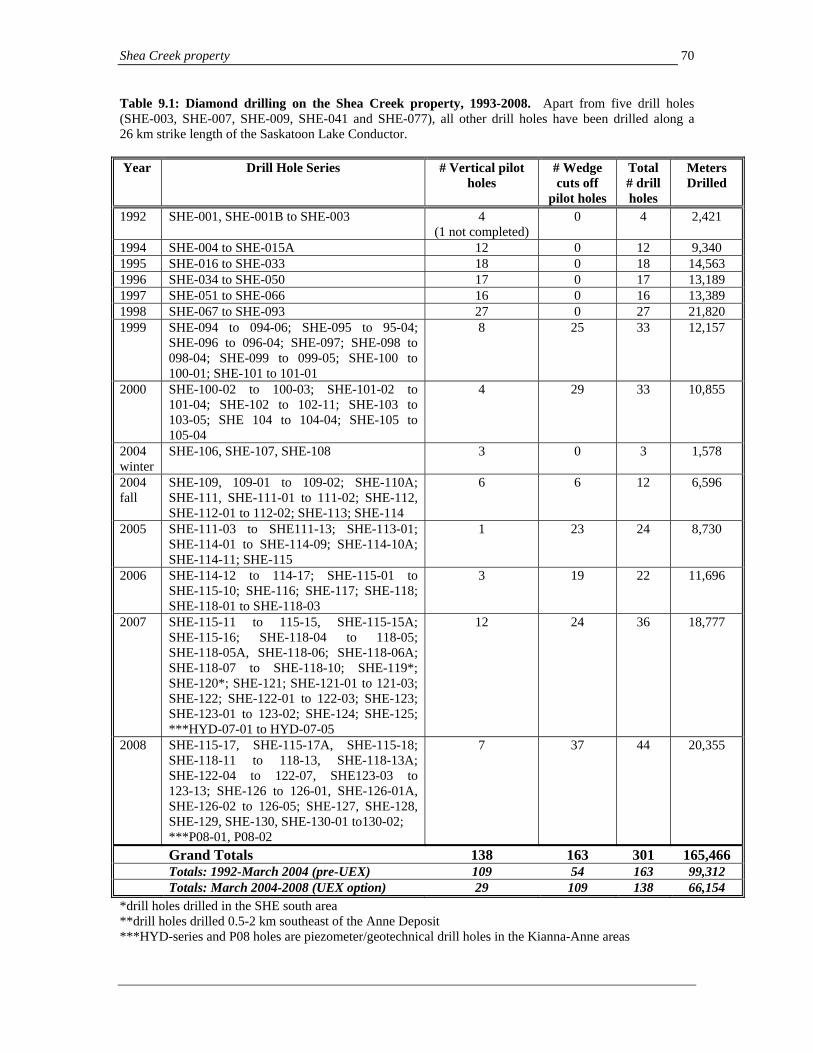
Shea Creek property 70
Table 9.1: Diamond drilling on the Shea Creek property, 1993-2008. Apart from five drill holes (SHE-003, SHE-007, SHE-009, SHE-041 and SHE-077), all other drill holes have been drilled along a 26 km strike length of the Saskatoon Lake Conductor. Year Drill Hole Series # Vertical pilot
holes # Wedge cuts off
pilot holes
Total # drill holes
Meters Drilled
1992 SHE-001, SHE-001B to SHE-003 4 (1 not completed)
0 4 2,421
1994 SHE-004 to SHE-015A 12 0 12 9,340 1995 SHE-016 to SHE-033 18 0 18 14,563 1996 SHE-034 to SHE-050 17 0 17 13,189 1997 SHE-051 to SHE-066 16 0 16 13,389 1998 SHE-067 to SHE-093 27 0 27 21,820 1999 SHE-094 to 094-06; SHE-095 to 95-04;
SHE-096 to 096-04; SHE-097; SHE-098 to 098-04; SHE-099 to 099-05; SHE-100 to 100-01; SHE-101 to 101-01
8 25 33 12,157
2000 SHE-100-02 to 100-03; SHE-101-02 to 101-04; SHE-102 to 102-11; SHE-103 to 103-05; SHE 104 to 104-04; SHE-105 to 105-04
4 29 33 10,855
2004 winter
SHE-106, SHE-107, SHE-108 3 0 3 1,578
2004 fall
SHE-109, 109-01 to 109-02; SHE-110A; SHE-111, SHE-111-01 to 111-02; SHE-112, SHE-112-01 to 112-02; SHE-113; SHE-114
6 6 12 6,596
2005 SHE-111-03 to SHE111-13; SHE-113-01; SHE-114-01 to SHE-114-09; SHE-114-10A; SHE-114-11; SHE-115
1 23 24 8,730
2006 SHE-114-12 to 114-17; SHE-115-01 to SHE-115-10; SHE-116; SHE-117; SHE-118; SHE-118-01 to SHE-118-03
3 19 22 11,696
2007 SHE-115-11 to 115-15, SHE-115-15A; SHE-115-16; SHE-118-04 to 118-05; SHE-118-05A, SHE-118-06; SHE-118-06A; SHE-118-07 to SHE-118-10; SHE-119*; SHE-120*; SHE-121; SHE-121-01 to 121-03; SHE-122; SHE-122-01 to 122-03; SHE-123; SHE-123-01 to 123-02; SHE-124; SHE-125; ***HYD-07-01 to HYD-07-05
12 24 36 18,777
2008 SHE-115-17, SHE-115-17A, SHE-115-18; SHE-118-11 to 118-13, SHE-118-13A; SHE-122-04 to 122-07, SHE123-03 to 123-13; SHE-126 to 126-01, SHE-126-01A, SHE-126-02 to 126-05; SHE-127, SHE-128, SHE-129, SHE-130, SHE-130-01 to130-02; ***P08-01, P08-02
7 37 44 20,355
Grand Totals 138 163 301 165,466 Totals: 1992-March 2004 (pre-UEX) 109 54 163 99,312 Totals: March 2004-2008 (UEX option) 29 109 138 66,154 *drill holes drilled in the SHE south area **drill holes drilled 0.5-2 km southeast of the Anne Deposit ***HYD-series and P08 holes are piezometer/geotechnical drill holes in the Kianna-Anne areas

Shea Creek property 71

Shea Creek property 72
6450000N
6440000N
6430000N5800
00E
5900
00E
6000
00E
Lakes
Colette
KiannaAnne
RoadsClaim boundariesSaskatoon Lake conductor
SHE-077
SHE-116
SHE-117
SHE-002
SHE-003
SHE-005SHE-006
SHE-010 / 010A
SHE-020 / 021
SHE-029
SHE-024
SHE-022
SHE-031SHE-127SHE-128
SHE-129
SHE-001
SHE-001B
SHE-041
SHE-039SHE-106
SHE-107
SHE-108
SHE-119
SHE-120
SHE-008
SHE-007
SHE-009
See Figs. 6.1, 9.1 for detailed drilling plan
DepositsDrillhole location
SheaSouth
SE Anne
N
E
S
W
Figure 9.3: Drilling in outlying parts of the Shea Creek property.

Shea Creek property 73
10.0 DRILLING (Form 43-10 F1 Item 13) Diamond drilling on the Shea Creek property is the principal method of exploration and mineralization delineation after initial geophysical surveys. Diamond drilling since 2004 has been conducted using drilling services supplied by either Midwest Drilling or Boart Longyear under contracts with AREVA (Koning et al., 2008). Drilling can generally be conducted year round in northern parts of the Shea Creek property, where the Anne, Colette and Kianna Deposits occur, due to dry ground above these areas. Drill holes on the Shea Creek Project are numbered with a prefix of the project (SHE) followed by the pilot hole number, and then if present, the cut number if wedging off the pilot hole has been completed. 10.1 Drilling methodologies Due to the >600 meter depths to target area, drilling is generally conducted by penetrating overburden with HW diameter casing followed by HQ coring to 400 meters depth. The holes are typically completed by reducing to NQ-sized core (48 mm core diameter), which is the typical core size testing mineralization at target depths (Koning et al., 2008). Drilling mud and polymer emulsions are added to the water to aid in freeing the drill cuttings and to help maintain stability of the walls of the drill hole so that the drill rods do not stick (Koning et al., 2008). Prior to 1999, all drill holes were drilled vertically from surface to the target at depth. From 1999 onward, directional drilling utilizing wedge cuts off the master (pilot) drill hole have been completed in areas where closely spaced drill holes are required to define mineralization or other geological features, reducing the overall quantity of coring required, and allowing controlled drilling of deep targets which are not easily reached from surface. New cuts are generally drilled off the pilot hole commencing 400 to 600 meters below surface, depending on the position of the target with respect to the pilot hole. The directional drilling process is summarized by Koning et al. (2008) as follows: “The directional drilling tool used up to 2004 consisted of a Sperry Sun steerable mud motor that is powered by hydraulic force that is created by a mixture of water and drilling mud pumped inside the drill string. A Bradley plug and wedge are set to initiate a directional cut. This usually achieves a 1.5° deflection off the original hole. The mud motor has a rotor–stator system that spins a non-coring cutting bit. A bent housing behind the bit allows the proposed drill hole to be deflected from a previous orientation. Additional pumps and mud tanks are required when the motor is in use. The motor uses an average of 220-250 L (50-55 gallons/min) of water when drilling (approximately 300,000 L or 66,000 gallons/day). It should be noted that the motor does not operate constantly during a 24 hour period. Some problems noted with the use of the mud motor are that it must be fixed to a BQ rod string; this hinders drill production due to the constant tripping in and out of drill rods. Another problem is the directional control of the bit since the motor is 6 meters behind the bit; there is always a risk of pulling the motor too early or too late. During the 2005 to 2008 drill campaigns, Devico’s (DeviDrill™) directional core drilling system was utilized. This system consists of a steerable core barrel that allows continuous survey measurements ahead of the bit while drilling, and provides core samples during the steering process. No additional equipment is required since the motor operates under normal water pressures used for diamond drilling. Thus there is no need for large supply pumps and mud tanks. Also a separate drill string (BQ) is not required since the motor is fixed to an NQ drill string. This in turn reduces the need for tripping an additional set of rods.”

Shea Creek property 74
10.2 Downhole directional surveys Downhole survey methodologies have varied during exploration on the Shea Creek property. Prior to 2000, drill hole deviation was measured every 30 to 50 meters with a Sperry Sun singleshot camera during normal drilling operations (Koning et al., 2008). During Sperry Sun directional operations, survey shots were taken preferably every 3 meters because control of the motor is 6 to 12 meters behind the drill bit. Since 2004 with the Devico system, drill hole deviation is measured every 50 meters with a Reflex single-shot probe during normal drilling operations (Koning et al., 2008). During directional operations survey shots are taken every 3 to 9 meters. 10.3 Radiometric probing of drill holes As is standard practice in uranium exploration, at the completion of each drill hole, down-hole radiometric geophysical probing surveys are performed from the bottom of the hole up through the drill string. The radiometric probe data, when calibrated by tool and local geology, can be utilized as a method of estimating mineralization grade which can either augment, or substitute for geochemical assays when there is statistically sufficient confidence in the calibration and conversion to uranium concentrations. Koning et al. (2008) describe probe methodologies at Shea Creek as follows: “Down-hole radiometric probes are used to detect radioactivity in the diamond drill holes. All probe runs are completed up-hole. The probes used in radiometric logging conducted by AREVA include the following tools; HLP-2375 manufactured by Mount Sopris, and ST22-2T, STD-27, and STD-27-HF (high flux) tools manufactured by AREVA. Radioactivity measurements obtained from the ST-22-2T, STD-27, and STD27-HF are used to estimate equivalent uranium grades for mineralized intervals. The Saskatchewan Research Council (SRC) provides down-hole probe calibration facilities in Saskatoon, SK, for calibration of the down-hole gamma probes. The test pits consist of four variably-mineralized holes, each approximately seven meters in length. The gamma probes are tested a minimum of once per year, usually in the fall, prior to the beginning of the winter field season. Also drill holes SHE-101-4 and 105-4, located at the Shea Creek project, are cased and remain accessible for use as calibration holes on the property to confirm the reliability of the probes. A Mount Sopris Model 2500 winch and MGX II logger (interface board) with a Mount Sopris HLP 2375 natural gamma probe were utilized to radiometrically log each drill hole. The down-hole data is acquired by a computer recovery program installed on a laptop computer. If the HLP-2375 natural gamma probe encounters and registers one reading of 1000 cps or more, the operator will be required to make an additional run using either an ST-22-2T or STD-27 tool. This ST-22-2T or STD-27 run is from 10 meters below to 10 meters above the first and last 1000 cps reading(s) recorded by the HLP-2375 natural gamma tool. In the case where very high-grade mineralization is encountered, another additional run is made using a STD-27-HF tool (high flux). The ST-22-2T and STD-27 use two ZP-1200 Gieger Müller tubes, whereas the STD27-HF uses two ZP-1320 Gieger Müller tubes which count at a rate of approximately one half that of the ZP-1200 tubes. The ZP-1320 tubes are therefore able to evaluate higher uranium grades which would saturate the ZP-1200 tubes.
Shea Creek property 75
Prior to probing, the drill hole is flushed with water. The probes utilized for in-hole probing are tested with a low-grade radioactive source prior to the logging run and after the completion of the logging run to ensure that the equipment was functioning properly before and after the in-hole probing occurred. Total gamma flux measurements are collected at 10 cm intervals during probing. The probe data is then transferred from the field computer into the drill hole database. The data acquired by the down-hole probes is then processed by in-house developed software to estimate the in-situ equivalent uranium grade and thickness of the mineralized interval(s). Several parameters are evaluated when converting the data including; diameter of the drill hole, thickness of steel casing, probe dead time in microseconds, diameter of the probe, casing coefficient, fluid coefficient, and a reference coefficient for the type of probe. A radioactivity-to-grade correlation is then applied to calculate the equivalent uranium grades. The software used to generate the radioactivity-grade correlation is known as Sermine, which is proprietary software developed by AREVA.” 10.4 Drill hole collar field locations and surveys Drill hole locations are measured in grid coordinates and later updated by UTM NAD83 coordinates surveyed by ARC personnel. Drill hole collars prior to 1998 have been located by conventional survey. Since that time drill hole locations have been surveyed using differential, base station GPS. After drilling, hole locations are marked with a tagged picket. 10.5 Summary of drilling composites and interpretation of results: northern Shea Creek property Composited drilling intercepts which have been obtained on the Shea Creek property since drilling began in 1992 are summarized in Appendix 2. The results are composited to a minimum grade of 0.05% U3O8 and a minimum grade (%U3O8)-thickness (length in meters) product (“GT”) of 0.1. Results reported are mainly geochemical results from analyses of uranium by ICP-MS and ICP-OES at the Saskatchewan Research Council Laboratories, as is documented in section 12.2 of this report. However, where 20% or more of a composited interval is not recovered during drilling (core loss), is unsampled, or where no geochemical sampling at all has occurred across a mineralized interval, down-hole radiometric probe equivalent grades reported as eU3O8 are substituted. The conversion coefficients for conversion of probe counts per second to eU3O8 equivalent for different parts of the Shea Creek property are documented in Koning et al. (2008) and summarized in Section 12.3 of this report. These conversions are based on correlation of probe results with geochemical results obtained from drilling on the property. The authors have reviewed these factors and believe them to form a reasonable estimate of uranium concentration. Infill geochemical sampling is recommended to provide more continuous geochemical results for areas where unsampled core remains in mineralized intervals, or where sampling did not fully bound the margins of mineralization. Note that the composited geochemical and probe results which are documented below, and in Appendix 2 of this report differ from, and supercede previously released probe results in 2004 to 2007 joint AREVA-UEX news releases, which utilized a probe conversion coefficient which has since been recalibrated using a more recent geochemical-probe correlation, as is documented in Section 12.3 of this report and disclosed in UEX’s news release of March 24, 2009.
Shea Creek property 76
10.5.1 Relationship of drilling length to true thickness of mineralized intercepts Drill holes on the northern Shea Creek property generally have steep dips of 75° or steeper. As a result, drilling generally crosses the flat-lying lenses of unconformity-hosted mineralization documented below and in Appendix 2 at a high angle that is close to, or at true thickness (e.g. Figures 8.1 to 8.5). Similarly lenses of perched mineralization, and of concordant basement mineralization are generally shallow dipping and crossed by drill holes at orientations which intercept mineralization at close to true thickness (Figures 8.1, 8.4). Mineralized intercepts of discordant basement mineralization have more complex morphology, and in most cases true thickness of intercepts are as yet undetermined (e.g. Figure 8.3). These discordant basement zones can contain combinations of steeply dipping vein-like mineralization which occurs at shallow core axis angles to many drill holes, in combination with foliation parallel, shallower dipping components which may form oreshoots. 10.5.2 Drilling in the Anne Deposit area Mineralization in the Anne Deposit has been traced continuously over approximately 450 m from the SHE-105 series drill holes on gridline 6550N to the vicinity of the 7000N fault (Figure 6.6). To date, 84 drill holes have been completed in this area, comprising both pilot drill holes and directional cuts (Appendix 1). Unconformity-hosted mineralization is the most extensive style identified to date at Anne. Thickest, highest grade intercepts define two pods (Figure 6.6), one in the south-central parts (around section 6750N) and the second in the northern parts of the Anne Deposit (around section 6875N). Highlights of the intercepts in this areas include the following, which are at, or close to true thickness:
• 4.324% U3O8 over 9.1 m, including 24.115% U3O8 over 1.4 m in hole SHE-016 • 5.446% U3O8 over 3.0 m, including 9.577% U3O8 over 1.5 m in hole SHE-079 • 11.607% U3O8 over 6.0 m, including 23.964% U3O8 over 2.9 m and 34.694% U3O8
over 1.9 m in hole SHE-087 • 1.283% U3O8 over 9.4 m in hole SHE-094-01 • 1.588% U3O8 over 11.0 m, including 4.608% U3O8 over 2.6 m in hole SHE-094-03 • 1.878% eU3O8 over 13.3 m, including 3.841% eU3O8 over 5.9 m in hole SHE-094-05 • 1.796% U3O8 over 8.9 m, including 6.367% U3O8 over 2.0 m in hole SHE-095-01 • 4.411% U3O8 over 14.9 m, including 20.898% U3O8 over 2.9 m in hole SHE-095-03 • 5.419% U3O8 over 19.0 m, including 29.200% U3O8 over 3.4 m in hole SHE-096-03 • 2.235% U3O8 over 7.5 m, including 7.477% U3O8 over 1.4 m in hole SHE-098 • 10.027% U3O8 over 8.4 m, including 34.149% U3O8 over 2.3 m and 60.601% U3O8
over 1.2 m, in hole SHE-099 • 0.959% eU3O8 over 22.7 m, including 4.368% eU3O8 over 3.4 m in hole SHE-099-01 • 5.649% U3O8 over 17.9 m, including 14.547% U3O8 over 6.5 m in hole SHE-099-02 • 2.612% U3O8 over 13.6 m, including 16.661% U3O8 over 1.9 m in hole SHE-099-03 • 3.315% U3O8 over 25.1 m, including 16.866% U3O8 over 4.0 m in hole SHE-100-01 • 3.746% U3O8 over 8.60 m, including 6.413% U3O8 over 4.9 m and 15.630% U3O8 over
1.5 m in hole SHE-101-02 • 4.420% U3O8 over 3.7 m in hole SHE-101-04 • 0.682% U3O8 over 22.2 m, including 5.789% U3O8 over 2.0 m in hole SHE-109-01 • 4.206% U3O8 over 36.0 m, including 13.703% U3O8 over 6.5 m in hole SHE-122-01

Shea Creek property 77
• 2.631% U3O8 over 8.0 m, including 13.000% U3O8 over 1.5 m in hole SHE-122-04 • 3.642% U3O8 over 20.5 m, including 11.407% U3O8 over 6.0 m and 15.635% U3O8
over 4.0 m in hole SHE-122-05 Note that the broad, high grade intercepts in drill holes SHE-95-03, SHE-096-3, and SHE-122-1 straddle the unconformity and extend into the underlying basement rocks (Figure 8.2). Basement mineralization at Anne is mainly concordant in style and occurs under the highest grade pods of unconformity mineralization described above. In southern parts of the Anne Deposit, it is mainly of the concordant basement style, while in the north it represents a combination of the concordant and discordant styles for which true thickness is generally undetermined. Principal intercepts include the following:
• 3.244% U3O8 over 9.0 m, including 10.159% U3O8 over 2.0 m in hole SHE-088 • 4.553% U3O8 over 3.9 m, including 7.925% U3O8 over 2.2 m in hole SHE-094-01 • 5.740% U3O8 over 2.8 m, including 14.089% U3O8 over 0.9 m in hole SHE-094-06 • 1.033% U3O8 over 10.7 m, and 1.854% U3O8 over 4.4 m in hole SHE-095-01 • 1.044% U3O8 over 19.8 m, including 5.511% U3O8 over 1.7 m in hole SHE-095-03 • 0.760% U3O8 over 18.0m, and 0.92% U3O8 over 20.8 m, in hole SHE-096-03 • 3.826% U3O8 over 2.5 m, including 13.132% U3O8 over 0.7 m in hole SHE-096-04 • 3.639% U3O8 over 7.5 m, including 16.954% U3O8 over 0.6 m in hole SHE-100-01 • 1.541% eU3O8 over 5.3 m in hole SHE-105-04 • 0.699% U3O8 over 15.5 m in hole SHE-109-02 • 23.171% U3O8 over 3.5 m, and 3.512% U3O8 over 8.5 m in hole SHE-122-01 (upper
basement zone) • 1.096% U3O8 over 10.5 m, including 4.025% U3O8 over 3.5 m in hole SHE-122-01
(lower basement zone) • 2.071% eU3O8 over 4.2 m in hole SHE-122-03 • 3.569% U3O8 over 4.0 m, including 6.661% U3O8 over 1.5 m in hole SHE-122-04
Perched mineralization in the Anne Deposit area is generally low grade, with a best intercept of 0.911% U3O8 over 3.6 m in hole SHE-046 in northwestern parts of the Anne area. Mineralization contiguous with unconformity mineralization in the high grade north central portions of the Anne Deposit may extend upward significantly into the overlying sandstone, but is not separated from the unconformity style as with perched mineralization in other areas and is included in the composited unconformity-hosted intersections reported here. Basement mineralization at Anne is potentially open for expansion in several areas, locally where earlier holes may not have penetrated to sufficient depth, and higher grade areas at the unconformity could be better defined by several infill drill holes. At the southeastern end of the Anne area, the SHE-105-series holes have intersected a combination of fault-hosted perched, basement and unconformity mineralization which is not bounded to the southeast. 10.5.3 Areas between the Anne and Kianna Deposits (Kianna South) The 400 meter distance between the Anne and Kianna Deposits is tested by 31 drill holes which are variable, but generally widely spaced. Drilling suggests that at least low grade mineralization at the unconformity here is contiguous between Anne and Kianna, and there is significant room at the unconformity between existing drill holes to expand some areas of higher grade mineralization. Drilling in this area has intersected significant unconformity-hosted

Shea Creek property 78
mineralization, mainly for up to 150 m south of the Kianna Deposit in the SHE-102 and SHE-123 series drill holes, which include:
• 0.901% U3O8 over 11.9 m in hole SHE-102-01 • 3.662% U3O8 over 5.3 m, including 11.065% U3O8 over 1.7 m in hole SHE-102-02 • 3.024% U3O8 over 3.7 m in hole SHE-102-07 • 1.418% U3O8 over 11.0 m, including 7.309% U3O8 over 1.3 m in hole SHE-102-10 • 11.114% U3O8 over 3.6 m, including 32.262% U3O8 over 1.1 m in hole SHE-123-06 • 5.198% U3O8 over 3.3 m, including 11.491% U3O8 over 1.3 m in hole SHE-123-07
These intercepts define a higher-grade pod of unconformity-hosted mineralization which is underlain by a zone of east-northeast trending clay alteration that contains several significant basement intercepts, including:
• 4.841% U3O8 over 3.5 m, including 7.850% U3O8 over 2.0 m in hole SHE-123-02 • 1.668% U3O8 over 7.5 m, including 18.392% U3O8 over 0.5 m in hole SHE-123-09 • 4.231% U3O8 over 2.0 m in hole SHE-123-12
Potential for additional basement-hosted mineralization in this areas is high. Based on the east-northeast trend of the associated clay alteration (Figure 6.6, Kianna South), basement mineralization could form a discordant mineralized zone of similar orientation to the main basement zone at Kianna. Clay alteration over 100 m to the west in hole P08-01 may represent a continuation of this clay zone. Minor perched alteration also occurs in this area, including 0.550% U3O8 over 4.5 m in hole SHE-123-03. In addition to these intercepts, a significant unconformity-hosted intercept comprising 8.664% U3O8 over 2.6 m in hole SHE-038A occurs approximately 300 meters south-southeast of Kianna, and is largely open to the northwest and southeast. Lower grade intercepts at the unconformity in widely spaced holes suggest unconformity mineralization is continuous throughout this area. 10.5.4 Kianna area Kianna is probably the most structurally focused uranium mineralization in the northern Shea Creek property. A total of 84 holes drilled in this area (this number includes geotechnical holes outside mineralization) have defined a broad east-northeast trending zone of clay alteration that is host to an overall steep northerly dipping and east-northeast trending zone of basement-hosted mineralization which extends at least 200 meters below the unconformity (Figure 8.3). Numerous significant intercepts have been obtained in this basement zone. True thickness to many of these is unknown. Some intercepts are drilled at shallow angles to mineralization, but many high grade sub-intervals within the broader intercepts also form shallow lenses with intercepts close to true thickness within the overall steeply dipping zone. These include:
• 3.578% U3O8 over 11.8 m, including 21.143% U3O8 over 1.5 m in hole SHE-114-08 (upper zone)
• 5.776% U3O8 over 6.5 m, including 16.793% U3O8 over 1.5 m in hole SHE-114-08 (lower zone)
• 1.100% U3O8 over 8.5 m, including 16.270% U3O8 over 0.5 m in hole SHE-114-09 • 4.093% U3O8 over 45.0 m, including 10.300% U3O8 over 3.5 m and 18.073% U3O8
over 6.0 m in hole SHE-114-11 • 7.719% U3O8 over 1.5 m in hole SHE-114-13 • 4.382% U3O8 over 7.8 m, including 20.023% U3O8 over 1.5 m in hole SHE-114-17

Shea Creek property 79
• 6.268% U3O8 over 3.5 m, including 40.086% U3O8 over 0.5 m in hole SHE-115-01 • 1.892% U3O8 over 4.5 m in hole SHE-115-02 • 3.643% U3O8 over 4.5 m, including 30.418% U3O8 over 0.5 m in hole SHE-115-05 • 0.811% U3O8 over 16.0 m, including 5.600% U3O8 over 2.0 m in hole SHE-115-06 • 3.694% U3O8 over 2.3 m, including 16.034% U3O8 over 0.5 m in hole SHE-115-07 • 1.059% U3O8 over 15.0 m, and 2.206% U3O8 over 7.5 m including 7.911% U3O8 over 2.0
m in hole SHE-115-08 • 1.840% U3O8 over 22.0 m, including 15.193% U3O8 over 1.5 m in hole SHE-115-09 • 8.581% U3O8 over 15.0 m, including 12.768% U3O8 over 10.0m, which includes
25.938% U3O8 over 1.0 m, and 24.346% U3O8 over 2.5 m in hole SHE-115-10 • 4.818% U3O8 over 2.0 m in hole SHE-115-14 • 3.731% U3O8 over 10.0 m, including 22.322% U3O8 over 1.5 m in hole SHE-115-15A • 0.837% U3O8 over 11.0 m in hole SHE-115-18 • 0.354% eU3O8 over 26.5 m in hole SHE-118-01 • 2.188% U3O8 over 9.5 m, including 7.951% U3O8 over 2.5 m in hole SHE-118-08 • 1.802% U3O8 over 5.0 m in hole SHE-118-09 • 19.244% U3O8 over 1.0 m in hole SHE-118-15
The high grade intercept in hole SHE-114-17 listed above is an isolated, largely open intercept which may form a separate, and new east-northeast trending zone to the north of the main zone of basement mineralization, or could be linked southward in a drilling gap to the main zone (Figure 8.3). The mineralization is bounded to the northeast by drill holes SHE-130-1 and -1A, but is otherwise open in all other directions and warrants high priority follow up. Portions of the main zone may also be open downdip and along strike, depending on overall morphology of the zone. The hosting clay zone remains open and strong to the northeast and southwest suggesting that the mineralized corridor could extend. Unconformity-hosted mineralization at Kianna forms a high-grade lens that lies above the basement mineralization. Intercepts are close to true thickness and occur over a 70 (north-south) by 150 m (east-west) area in plan view. Significant intercepts include:
• 1.018% U3O8 over 12.1 m in hole SHE-114-09 • 9.335% U3O8 over 12.2 m, including 20.285% U3O8 over 0.9 m, and 21.154% U3O8
over 4.3 m in hole SHE-115-03 • 2.547% U3O8 over 19.0 m, including 5.847% U3O8 over 7.0 m, which includes
11.080% U3O8 over 2.0 m in hole SHE-115-04 • 7.827% U3O8 over 7.2 m, including 20.360% U3O8 over 2.7 m in hole SHE-115-05 • 2.227% U3O8 over 10.6 m, including 7.263% U3O8 over 1.5 m in hole SHE-115-06 • 6.297% U3O8 over 7.9 m, including 9.394% U3O8 over 4.9 m, which includes
18.098% U3O8 over 1.0 m in hole SHE-118 • 1.271% U3O8 over 16.9 m, including 4.763% U3O8 over 4.0 m in hole SHE-118-01 • 0.981% eU3O8 over 17.3 m in hole SHE-118-04 • 1.577% U3O8 over 13.2 m, including 5.510% U3O8 over 3.5 m, which includes 10.149%
U3O8 over 1.5 m in hole SHE-118-05 • 1.475% U3O8 over 15.0 m, including 5.791% U3O8 over 3.5 m, which includes 12.556%
U3O8 over 1.0 m in hole SHE-118-05A • 2.609% U3O8 over 6.0 m, including 8.180% U3O8 over 1.8 m in hole SHE-118-06A • 4.028% U3O8 over 6.0 m, including 11.831% U3O8 over 2.0 m in hole SHE-118-06B • 2.030% U3O8 over 10.0 m, including 8.468% U3O8 over 2.3 m in hole SHE-118-08

Shea Creek property 80
• 2.275% U3O8 over 11.5 m, including 5.011% U3O8 over 4.3 m, which includes 8.037% U3O8 over 1.5 m in hole SHE-118-09
• 5.863% U3O8 over 3.2 m, including 24.300% U3O8 over 0.6 m in hole SHE-118-11 • 1.542% U3O8 over 6.8 m in hole SHE-118-13 • 1.254% U3O8 over 13.0 m in hole SHE-118-14 • 1.114% U3O8 over 17.5 m, including 5.124% U3O8 over 2.5 m in hole SHE-118-15
Kianna also has significant perched mineralization which forms at least two lenses above the higher grade areas of unconformity-hosted mineralization, at distances of 20 to 70 meters above the unconformity. A moderate southwest dip to some of this mineralization is apparent, which may link to southwest dipping faults in the basement rocks downdip to the southwest. Some very high grade intercepts have been obtained in this zone:
• 20.721% eU3O8 over 10.2 m, including 27.729% eU3O8 over 7.6 m in hole SHE-114-05
• 7.367% U3O8 over 9.5 m, including 10.700% U3O8 over 6.5 m, which includes 21.163% U3O8 over 2.0 m in hole SHE-114-07
• 4.637% eU3O8 over 22.2 m, including 8.001% eU3O8 over 3.2 m, and 7.851% eU3O8 over 8.8 m in hole SHE-114-09
• 4.580% eU3O8 over 15.3 m, including 9.967% eU3O8 over 6.4 m in hole SHE-114-11 • 1.815% U3O8 over 10.0 m, including 3.490% U3O8 over 4.0 m in hole SHE-115-06 • 6.165% U3O8 over 6.70 m, including 20.134% U3O8 over 2.0 m in hole SHE-115-08 • 1.213% eU3O8 over 26.41 m in hole SHE-115-08 (lower zone) • 8.420% eU3O8 over 12.6 m in hole SHE-115-18
10.5.5 58B area Only 18 drill holes have been completed in the one kilometer strike between the Kianna and southern Colette Deposits in this area, and gaps in drilling along the trace of the pelitic gneiss unit at the unconformity are as wide as 400 meters where only one hole has been completed northwest of Kianna (Figure 9.2). The best intercepts in the area have occurred around drill hole SHE-058B, which is located 600 meters north-northwest of Kianna and 400 meters southeast of the Colette South area (Figure 6.2). In addition to intersecting 8.8 m of lower grade unconformity-hosted mineralization, SHE-058B intersected multiple mineralized intervals in the basement, including 2.213% U3O8 over 2.6 m, that also included 6.732% U3O8 over 0.7 m; true thickness and orientation of mineralization are unknown. The basement rocks to these intervals are strongly altered granitic gneiss. Overall style and alteration intensity suggest high potential for further basement mineralization here, which is open in all directions. The closest drill holes to hole SHE-058B are the SHE-103 and SHE-104 series holes 50 to 200 meters to the northwest and southeast, which have locally intersected unconformity (e.g. 0.242% eU3O8 over 28.2 m in hole SHE-103-01) and basement (0.470% eU3O8 over 5.8 m in hole SHE-104-03) mineralization. A left-handed deflection in the pelitic gneiss unit between hole SHE-058B and the SHE-103 series drill holes to the south, coupled with the well developed basement alteration here, may suggest the presence of an east-west trending fault zone which could host discordant styles of basement mineralization.

Shea Creek property
81
10.5.6 Colette area Drilling in the Colette area includes 59 drill holes distributed between the main portions of Colette to the north (38 drill holes) and the area of Colette South (21 holes). The two areas have different styles. Main portions of Colette, northwest of the 8800N fault (Figure 6.5) are of dominantly unconformity-hosted mineralization, with best intercepts occurring along the projected traces of the northeast trending 8800N and Colette faults (Figure 6.5). The best unconformity intercepts, which are at or close to true thickness, include:
• 1.432% U3O8 over 12.2 m, including 2.916% U3O8 over 5.6 m in hole SHE-045 • 2.342% U3O8 over 16.8 m, including 4.294% U3O8 over 7.8 m and 7.547% U3O8 over
2.7 m in hole SHE-052 • 4.099% U3O8 over 6.6 m, including 6.493% U3O8 over 3.9 m in hole SHE-059 • 1.732% U3O8 over 11.9 m, including 3.476% U3O8 over 4.6 m in hole SHE-065 • 1.122% U3O8 over 11.0 m in hole SHE-078 • 1.517% U3O8 over 8.9 m in hole SHE-091
At the northwestern margins of the Colette Deposit, a flat lying perched zone of mineralization occurs 30 to 50 meters above the unconformity, which has yielded several intercepts that include 1.578% U3O8 over 1.6 m in hole SHE-052, 0.720% U3O8 over 4.7 m in hole SHE-066, and 0.725% U3O8 over 4.5 m in hole SHE-074. In the Colette South area, the most significant drilling intercepts are of basement mineralization. Here, drilling in the SHE-111 and SHE-126 series drill holes has defined a series of stacked concordant style zones of basement mineralization (Figure 8.4) over a strike length of at least 250 meters. The best intercepts include:
• 0.907% eU3O8 over 10.8 m, including 3.91% eU3O8 over 1.2 m in hole SHE-111-02 • 0.343% eU3O8 over 6.6 m in hole SHE-111-03 • 0.582% eU3O8 over 16.2 m, and 2.458% U3O8 over 1.0 m in hole SHE-111-05 (two
stacked basement zones) • 3.227% U3O8 over 8.0 m, including 12.380% U3O8 over 0.5 m and 23.934% U3O8
over 0.5 m in hole SHE-111-06 • 1.429% U3O8 over 6.0 m, and 0.633% U3O8 over 4.5 m in hole SHE-111-11 (two stacked
basement zones) • 0.879% U3O8 over 11.5 m, including 4.810% U3O8 over 1.0 m in hole SHE-111-12 • 0.402% U3O8 over 13.8 m in hole SHE-126 • 0.700% U3O8 over 10.2 m, including 4.521% U3O8 over 1.0 m in hole SHE-126-01A
Mineralization is open downdip to the southwest on several sections. The presence of the adjacent 8800N fault to the northwest, and deflections in the pelitic gneiss that may represent prospective east-west faulting development, make this area a high priority target for additional, and potentially higher grade Kianna style uranium mineralization in basement rocks.

Shea Creek property 82
10.6 Drilling in other areas on the Shea Creek property Outside the northern three kilometers of the Shea Creek property where exploration has been focused on the Anne, Kianna and Colette Deposits, only 26 drill holes test other parts of the Shea Creek property. These holes have been focused in three mains areas (Figure 9.3):
(i) along the Saskatoon Lake Conductor for approximately 3 km southeast of the Anne Deposit,
(ii) in southernmost portions of the Shea Creek property along extensions of the Saskatoon Lake Conductor, and
(iii) several holes which have tested EM and resistivity anomalies west of the Colette Deposit. Drilling in these three areas is briefly reviewed below. Outside of these areas three isolated drill holes, SHE-007, SHE-003, and SHE-009, have been drilled mainly to test EM and resistivity targets (Figure 9.3). None of these holes intersected any significant alteration or mineralization. Two drill holes, SHE-008 and SHE-041 have been drilled on claims that are no longer part of the Shea Creek property (Figure 9.3). Given the sparseness of drilling on most of the property, including significant portions of the strike length of the Saskatoon Lake Conductor, and the high frequency of mineralization in the region, exploration potential is considered to be high. Future expansion of existing DC resistivity survey coverage (Figure 9.1), and/or other new technologies such as Low Temperature Superconducting Quantum Interference Device (LT SQUID) surveys, is recommended to identify targets in other parts of the property. SE Anne area Fourteen diamond drill holes drilled on widely spaced cross sections have tested the Saskatoon Lake Conductor and its margins for up to three kilometers southeast of the Anne Deposit, (Figure 9.3). The earliest drill holes in this area include several holes from the initial 1992 drill program prior to the discovery of the Anne and Colette Deposits. These initial drill holes targeted the Saskatoon Lake Conductor when it was first recognized in airborne and ground EM geophysical surveys by Amok Limited in 1990 to 1992 (Alonso et al., 1992). Drilling here has intersected extensions of the same geology as in the northern parts of the property, with faulting continuing to be localized along the pelitic gneiss unit, and inducing a north-northwest trending fault-related fold offset of the Athabasca unconformity that is coincident with the pelitic gneiss unit. The vertical depth to the unconformity in the Anne area ranges in depth from 683.8 m in drill hole SHE-031 to 786.3 m in hole SHE-129. The most significant result in the area to date is SHE-002, drilled in 1992, which intersected a shallow dipping brecciated fault zone grading 0.34% U3O8 over 0.4 m from 706.8 to 707.2 m. The mineralization occurs in a zone of significant hydrothermal alteration and structural disruption in the basal Athabasca sandstone and the basement below the unconformity (Alonso et al., 1992) which is associated with green/black graphite-rich breccia that contains typical alteration associated with mineralization to the north in the main Shea Creek deposits, including illite, sudoite, dravite, and minor phosphates (goyazite). Principal uraniferous and associated minerals include uraninite which is auriferous (up to 2.4 g/t Au), coffinite and associated niccolite. Minor mineralization was also intersected in drill hole SHE-127, which was located 200 meters northwest of SHE-002. Fracture controlled mineralization was intersected in the basement rocks of this hole grading 0.24% eU3O8 over 0.5 m between 736.9 and 737.4 m. Anomalous radioactivity is also present in several further drill holes, including SHE-024, drilled approximately 1.4 kilometers to the northwest of SHE-002. SHE-024 intersected sooty pitchblende mineralization accompanied by hematization along foliation planes within the

Shea Creek property
83
basement rocks grading 0.074% U3O8 over 2.30 m from 723.8 to 726.1 m (Alexander et al., 1995). In addition to the mineralization mentioned above, other drill holes in this area have also intersected intervals of strongly bleached and locally brecciated sandstone that contains moderate quartz, clay and dravite filled hydraulic fractures, locally pervasive sudoite and dravite alteration, and anomalous uranium content in the lower sandstone column (Alonso et al., 1992; Alexander et al., 1995). Significant hydrothermal alteration (dravite, drusy quartz and black carbonaceous material) also locally extends into the basement. All of these features continue to suggest that this area is highly prospective for uranium mineralization. In southern parts of this area, a significant change in unconformity elevation on, and south of the drill section containing holes SHE-010A, SHE-029, and SHE-031 suggests the possible presence of an oblique fault with potential-post-Athabasca displacement which may vertically offset the Saskatoon Lake Conductor and unconformity. If so, the fault, or its marginal effects may form a prospective exploration target, in addition to the follow up of the mineralization and alteration intersected in the drill holes to the northwest. Southeast of this area, the Saskatoon Lake Conductor is only tested by one drill hole (SHE-007), which did not intersect or test the conductor, over a more than 8 km strike length to the property boundary. Shea South Drilling in the Shea South area has targeted the southernmost extensions of the Saskatoon Lake Conductor on the Shea Creek property, where it trends north to north-northeast near the Beatty River shear zone (Figure 9.3). Eight drill holes have tested an approximately two kilometer strike length of the conductor on three widely spaced sections in this area. The vertical depth to the unconformity in the Shea South area ranges from 406.4 m in hole SHE-001B to 495.2 m in hole SHE-107. Drilling has intersected up to 25 meters of garnet bearing pelitic and graphitic gneiss which has localized graphitic faulting (Munholland et al., 1996). The lower sandstone column is locally altered, particularly in SHE-001B, where it is strongly faulted and block tilted with intense argillization, silicification (drusy and vein quartz) and bleaching (Alonso et al., 1992). Anomalous values of nickel and arsenic occur in the sandstone of hole SHE-001B and elevated boron values (up to 184 ppm B) correlate with dravite detected from reflectance spectral analysis (PIMA) towards the base of the sandstone column in the adjacent hole SHE-106 (Robbins and Williamson, 2004). Although no mineralization has been intersected here, alteration and basement faulting are favorable, and additional drill testing of this area will be required. Outlying Areas Three drill holes have been drilled in the Klark Lake target area up to 2.4 km west of the mineralization intersected in the Collette area (Figure 9.3). The first hole, SHE-077, tested the potential for mineralization along the Klark Lake conductor at the unconformity (Robbins et al., 1998). No significant alteration, mineralization or graphitic basement was intersected in this hole. Subsequent holes SHE-116 and SHE-117 tested the resistivity low which lies immediately west of the Colette Deposit (Figure 9.1). In SHE-117, the basal sandstone column is strongly bleached and silicified above the unconformity with numerous intervals of brecciation and dravite, silica and fragmental rich matrices from 650 m to 670 m. Brecciated areas are associated with elevated radiometrics where a peak of 200 cps from the SPP2 scintillometer corresponds to a quartz - coffinite (?) filled fracture (Robbins et al., 2007). No graphitic basement has yet been intersected in the Klark Lake area.
Shea Creek property 84
10.7 Relationship between sample length and true thickness Since the orientations of drill holes in the deposits vary, and the morphology of mineralized zones has variable orientation, the relationship of geochemical sample length and probe composited lengths in drill holes to the true thickness of mineralization is also variable. For mineralization developed at the unconformity in the Anne, Kianna and Colette Deposits, the steep orientation of most drill holes crosses the flat-lying mineralization in intercepts which are at or close to true thickness. For basement-hosted mineralization, in many areas thickness has not yet been determined since the morphology and orientation of mineralization is still interpretive so thickness is apparent. In some areas in the southern Anne Deposit, where basement mineralization is parallel to the metamorphic stratigraphy and a higher confidence level of its morphology has been determined, intercepts are close to true thickness. Perched mineralization at Kianna has been intersected by multiple closely spaced drill holes which indicate it has a lens-shaped shallow southwesterly dip, resulting in drill hole intercepts which are also generally close to true thickness. 11.0 SAMPLING METHOD AND APPROACH (Form 43-101F1 Item 14) 11.1 Drill core handling and logging procedures At the drill rig, core is removed from the core barrel by the drillers and placed directly into three row NQ wooden core boxes with standard 1.5 m length and a nominal 4.5 m capacity. Individual drill runs are identified with small wooden blocks, onto which the depth in meters is recorded. Diamond drill core is transported at the end of each drill shift to an enclosed core-handling facility at the Cluff Lake camp. The core handling procedures at the drill site are industry standard. Drill holes are logged at the Shea Creek Exploration core logging facilities located on the Cluff Lake mine site. All core logging and sampling is conducted by AREVA personnel. At the core logging facilities, the core is measured to determine core recovery on a per meter basis and then scanned for radioactivity using a shielded SRAT SPP2 scintillometer (measuring between 10 to 15,000 counts per second), SRAT SPPγ (measuring between 10 to 40,000 counts per second), a GMT-3T Geiger-Müller instrument (measuring between 0 to 5,000 counts per second AVP), or a GMT-15T Geiger-Müller instrument (measuring between 0 to 50,000 counts per second) (Koning et al., 2008). As per AREVA standard practices (Koning et al., 2008), a color code is used when writing radioactive values on the core box; from 0 to 3,000 cps SPP2 or SPPγ a black marker is required; from 3,000 to 40,000 cps SPP2 or SPPγ a red marker is required; 0 to 50,000 cps AVP a blue marker is required (note: 1 cps AVP is roughly equivalent to 10 cps SPP2 or SPPγ). Readings between 0 to 3,000 cps SPP2 or SPPγ are considered to be weakly mineralized, readings between 3,000 to 40,000 cps SPP2 or SPPγ are considered to be moderately to strongly mineralized, and all readings in AVP are considered to be strongly mineralized (Koning et al., 2008). Along with other geological parameters, these readings form the basis for the selection of geochemical sampling intervals. Further treatment of mineralized intervals and core logging are described by Koning et al. (2008) as follows: “If a zone of anomalous radioactivity has been intersected, the radiometric readings over the length of core are recorded in 10 cm intervals. The measured intervals are documented and are recorded in the drill hole database. The measured radiometric values on core are compared to down-hole radiometric probe readings taken of the mineralized interval to correlate and correct

Shea Creek property 85
probe recording depths. The recording of down-hole probe depths can be affected by stretching of the co-axial cable on which the probe is connected, especially for deep drill holes. Therefore adjustments may be required to the depth intervals of down-hole probe data to correct for this potential source of error and possible driller error. Once the core is radiometrically scanned, geologists log the drill core by recording their observations on field logs, including descriptions of; lithologies, mineralized intervals, friability, grain size in the sandstone, fracture density, alteration, color, structure, and a descriptive log of the core. This data is then transferred from the field log to computer and imported into DrillKing, a drill hole logging and software database program developed by SURPAC Software International.” In addition to the geological log, all core is routinely wet down and digitally photographed prior to geochemical sampling with a digital camera as a permanent record. Once each core box is logged and sampled, it is clearly identified with a metallic embossing tape and stored in the core storage compound. Beginning with the last 100 m above the unconformity to the bottom of the hole, the core boxes are placed in core racks within a fenced compound. The upper part of the drill hole core is stacked in perpendicular rows outside the fenced compound. All drill core is stored at the northeast end of Cluff Lake, on the Cluff Mining surface lease (UTM coordinates; 585925E and 6469787N). The core handling and logging procedures were actively observed by the authors at the Cluff Lake core logging facility. In the authors’ opinion, these are performed to industry standards. 11.2 Drill core sampling Several types of samples are collected routinely from drill core at Shea Creek. These include:
1) systematic composite geochemical samples of both Athabasca sandstone and sub-Athabasca metamorphic basement rocks to characterize clay alteration and geochemical zoning associated with mineralization,
2) selective grab samples and split-core intervals for geochemical quantification of
geologically-interesting material and mineralized material, respectively, 3) samples collected for determination of specific gravity – dry bulk density, and 4) non-geochemical samples for determination of mineralogy to assess alteration patterns,
lithotypes and mineralization characteristics. Selective samples form a quantitative assessment of mineralization grade and associated elemental abundances, while the systematic and mineralogical samples are collected mainly for exploration purposes to determine patterns applicable to mineral exploration. These sampling types and approaches are typical for uranium exploration and definition drilling programs in the Athabasca Basin.

Shea Creek property 86
Principal sampling methodologies are described by Koning et al. (2008) as follows: “Systematic composite sampling In systematic composite sampling, the sandstone and basement portions of each drill hole are systematically “chip”-sampled. The sample chips are small (2-3 cm length) core pieces taken from the end of each core box row within the composite interval. These composite intervals are a maximum of 20 m in width in the sandstone and are <10 m in width in the basement. In the sandstone, 20 m composites are taken from the top of the drill hole core to about 100 m above the sub-Athabasca unconformity, at which point 10 m composites are taken down to ~1 m above the unconformity. A narrow-interval composite 1 m chip sample is taken above the unconformity using core pieces taken at 20 to 30 cm intervals. Samples are labeled in the “1SYS” series for initial sampling and then “3SYS”, “4SYS”, etc. for resampling of the drill core. Sample field duplicates are anonymously included in the same series as the original samples. Systematic sampling of basement lithologies follows a similar pattern. The first 1 m below the unconformity is chip-sampled with fragments taken at 20-30 cm intervals. Below this, the limits of the composite samples are dictated by the widths of individual lithological/alteration units, with a maximum length of 10 m. The sample composites do not cross lithological/alteration contacts. As for the sandstone sampling, the sample chips are taken from the end of each core box row within composite interval. These basement systematic composite samples are labeled in the “1SYB” series, then “2SYB”, “3SYB”, etc. for resampling of the drill core. The geochemical data from these systematic composite samples are used only for exploration purposes, for example, to determine trends in elemental enrichments/depletions and to determine the normative clay mineral (kaolin, illite, Mg-chlorite, dravite) proportions. These data are not used in the mineral resource calculations. Selective sampling Selective sampling for geochemistry and mineralogy includes split-core sampling of all of the mineralized intervals and unsplit grab sampling. Sample lengths of the mineralized split-core samples are from 20 cm to 50 cm, but are generally 50 cm. Selective samples less than 50 cm in length are taken to represent the presence of narrow mineralized zones, such as fracture fills or small veins. Selective samples over 50 cm in length are rarely taken, and only in zones of low radioactivity or zones having a homogenous radioactivity. The barren wall rock on either side of the mineralized intervals is also sampled. The minimum field radiometric value above which samples are regarded as 'mineralized' is 200 cps using a SPP2 or SPPγ scintillometer. The unsplit grab samples are taken to characterize specific features of interest in the core, for example fracture zones and clay-altered regions. These samples are generally ‘fist-sized’. Selective samples from the sandstone are labeled in the “1SEL” (“2SEL”, “3SEL”, etc. for resampling purposes) while basement samples are in the “1BAS” series (2BAS, 3BAS, etc. for resampling purposes). The sample interval is split using a hydraulic splitter, one half for analysis and the other half left in the core box. The splitter is cleaned after the sampling of each mineralized interval.

Shea Creek property 87
Specific Gravity and Dry Bulk Density sampling No separate samples are taken for use in specific gravity determinations. The powdered pulps or the crushed reject part of samples taken for geochemical analysis are used in these determinations. However, separate samples are taken for use in determinations of dry bulk density and other physical property measurements. These samples consist of a 10 to 15 cm length of unbroken, non-fractured core. These samples are not crushed and ground, but are cut to 10 cm in length with a rock saw so that the core ends are perpendicular to the core axis and then submitted for analysis. These latter samples are labeled in the “1MAS” series. Other sampling Sampling is also carried out so that the distribution(s) of the clay mineral species (plus hydrothermal dravite) can be determined. These samples are sandstone or basement chips normally taken at 3 m intervals, generally at core run markers. The clay mineralogical determinations are obtained on a whole-rock basis by SWIR (Short Wave InfraRed) spectrometry using either a PIMA or ASD TerraSpec spectrometer. The resulting data are clay mineral proportions (kaolinite, dickite, halloysite, illite, chlorite and dravite). These samples are labeled in the “1PIC” series and “1PICB” series for sandstone and basement samples analysed using the PIMA spectrometer, or in the “1TER” series and “1TERB” series for sandstone and basement samples analysed using the TerraSpec spectrometer. Samples have been taken from a number of drill holes for determination of rock physical properties (wet and dry density, porosity, electrical resistivity, magnetic susceptibility, and P- and S-wave acoustic velocity). These samples, labeled in the “1MAS” series (“2MAS”, “3MAS”, etc. for resampling purposes), consist of one piece of unfractured core that is a minimum of 10 cm in length. The core samples were taken at approximately 20 m intervals down the drill holes. The physical property determinations were carried out in the Rock Mechanics Lab (Department of Geological Sciences, University of Saskatchewan, Saskatoon, SK). As needed, whole-core samples are also taken for petrographic examination and description, with the examinations being carried out in-house or contracted to an external service provider. These samples are labeled in the “TS” series.” Systematic geochemical profiling and clay analysis Systematic samples are taken throughout the sandstone column above the unconformity to determine clay alteration and geochemical haloes within the sandstone column. These samples consist of a series of systematically spaced (1.5 m) rock chips collected over 20 m composite sample intervals, except within the last 100 m above the unconformity, where samples are collected at 10 m sample intervals (Koning et al., 2008). The sample depth is recorded as the start point of the interval. Each sample is geochemically analysed for a suite of elements, including a minimum of K2O, Al2O3, MgO, Pb, Boron, and U (total). Samples are also taken for mineralogical analysis by X-Ray Diffraction (XRD) or by Short Wave Infrared Reflectance (SWIR) spectrometry using the Portable Infrared Mineral Analyser (PIMA) or ASD TerraSpec® instruments, which allow in particular determination of phyllosilicate-clay and carbonate assemblages. 11.3 Sample quality, selection, representativity and potential bias Selective geochemical sampling by AREVA personnel at the Shea Creek property, the only geochemical sampling type used here to determine grade and extent of uranium mineralization, is

Shea Creek property 88
considered by the authors to be representative of the mineralized intervals, and reliably reflective of both grade and mineralization distribution. In conjunction with visual characterization by the geologist, the systematic scintillometer analysis of mineralized intervals allows samples to be selected and collected from representative intervals which have common grade characteristics, distinguishing high from lower grade intervals. Sampling intervals are further divided if significant changes in lithology, alteration or core recovery are encountered. The majority of selective samples in the Shea Creek database have 0.5 m sample lengths, but may also frequently range between 0.1 and 0.7 m. During the course of reviewing the drill core on site and compositing results, it was noted that some mineralized intervals have not been sampled geochemically, contain gaps in sampling between closely spaced areas of mineralization, or where previous sampling was carried out has not fully bounded mineralized zones. Sampling of these intervals is recommended to provide more complete geochemical profiles through mineralized zones. Core recovery considerations for selective samples, and use of probe data An important consideration in both sample selection and representativity of selective geochemical samples is core recovery. In general, core recovery, which as described above is noted per meter in core logging, is very good and typically greater than 95%. However, there are sections within the lower sandstone column and near the unconformity where core recovery is poor in areas of desilicified sandstone and clay alteration that sometimes overlap with mineralized intervals. Locally in such areas, low, or no core recovery, may occur over intervals of up to several meters. Such issues are rarer in the underlying basement gneiss sequence. It is AREVA’s policy not to sample a mineralized interval if there is less than 75% recovery of the core over a 50 cm sample width (Koning et al., 2008). In such cases, downhole radiometric probe data can be substituted in place of radiometric grades, since as described in section 12.3, probe data correlates positively with uranium grade, and probe data are calibrated in areas of good recovery to geochemical values. In the author’s review of previously sampled drill core on site, some intervals were noted to have remained unsampled geochemically in areas of mineralization even where core recovery was good. For completeness, further infill sampling is recommended to provide more complete geochemical profiles. In addition, sampling of previously unsampled areas with less than 75% recovery is recommended to provide an additional check of probe data. Sample quality Selective sampling of drill core is collected to industry standards by splitting half core, with retention of half in the core box. No inherent sampling biases were observed in the longitudinal splitting of the core and sample processes. The correlation of downhole radiometric probing, detailed radiometric SRAT SPP-2, SRAT SPPγ, GMT-3T or GMT-15T readings, as well as assay comparison and the quality assurance/quality control (“QA/QC”) program (Section 14) provide further levels of confidence. Authors’ opinion on core handling and logging procedures In the authors’ opinion, the core sizes, procedures for logging, recording of core recoveries, and sampling are standard industry practices. These, in conjunction with calibrated probe data in areas of poor recovery, will provide an acceptable basis for the geological and geotechnical interpretation of the deposits leading to the future estimation of mineral resources, and subsequent economic evaluation of the deposits.

Shea Creek property 89
12.0 SAMPLE PREPARATION, ANALYSIS AND SECURITY (Form 43-101F1 item 15) On site, after sampling from drill core is completed, plastic bags containing the individual geochemical samples (systematic and selective) are grouped according to lithology (sandstone or basement) and radioactivity. Non-radioactive samples are placed in white plastic pails while the radioactive samples are placed in black painted metal “IP3” containers (Koning et al., 2008). The radioactive samples are shipped within Canada in compliance with pertinent federal and provincial regulations regarding their transport and handling. The sample pails/containers are shipped to the Saskatchewan Research Council (SRC) Geoanalytical Laboratories in Saskatoon for analysis, which is located at 125-15 Innovation Blvd., Saskatoon, Saskatchewan. The laboratory has an ISO/IEC 17025:2005 accredited quality management system (Scope of Accreditation # 537), from the Standards Council of Canada (SRC, 2007), and is accredited by the Canadian Association for Laboratory Accreditation Inc. After the analyses described below are completed, analytical data are securely sent by SRC to AREVA through the use of electronic transmission of the results. The electronic results are secured through the use of WINZIP encryption and password protection. These results are provided as a series of Adobe PDF files containing the official analytical results and a Microsoft Excel spreadsheet file containing only the analytical results. SRC is an independent laboratory, and no associate, employee, officer or director of UEX is, or ever has been, involved in any aspect of sample preparation or analysis on samples from Shea Creek, or any other properties. Sample preparation and analytical procedures sections outlined below are sourced from Koning et al. (2008), and SRC (2007). 12.1 Sample Preparation On arrival at the SRC lab, all samples are received and sorted into their matrix types (sandstone versus basement) and received radioactivity levels (using a multi-dot classification system). Sample preparation (drying, crushing, and grinding) is done in separate facilities for sandstone and basement samples to reduce the probability of sample cross-contamination. Crushing and grinding of radioactive samples (2 dots or higher; i.e. more than 2,000cps) is done in another separate, Canadian Nuclear Safety Commission (“CNSC”) licensed radioactive sample preparation facility. Radioactive material is kept in a CNSC-licensed concrete bunker until it can be transported by certified employees to the radioactive sample preparation facility. Sample drying is carried out, with the samples in their original bags, overnight in large low temperature (80° C) ovens. Following drying, the samples are crushed to 60% <2 mm using a steel jaw crusher. A 100 to 200 g split is taken of the crushed material using a riffle splitter. This split is then ground to 90% <106 microns (<150 mesh) using a Cr-steel puck-and-ring grinding mill (for mineralized samples) or a motorized agate mortar & pestle grinding mill (for all non-mineralized samples). The resulting pulp is transferred to a clear plastic snap-top vial with the sample number labeled on the top. All grinding mills are cleaned between sample runs using steel wool and compressed air, with a between-sample grind of silica sand if the previous samples were clay-rich. Prior to the primary geochemical analysis, the sample material is digested into solution using several digestion methods. A “total” tri-acid digestion, on a 250 mg aliquot of the sample pulp, uses a mixture of concentrated HF/HNO3/HClO4 acids to dissolve the pulp in a Teflon beaker over a hotplate and the residue, following drying, is dissolved in 15 ml of dilute ultrapure HNO3.

Shea Creek property 90
A “partial” acid digestion, on a 2 g aliquot of the sample pulp, is digested using 2.25 ml of 8:1 ratio ultrapure HNO3 and HCl for 1 hour at 95°C in a hot water bath and then diluted to 15ml using deionized water. For fluorimetric analysis of U, an aliquot of either total digestion solution or partial digestion solution is pipetted into a Pt-Rh dish and evaporated. A NaF/LiK pellet is placed on the dish and the sample is fused for 3 minutes using a propane rotary burner and then cooled to room temperature before fluorimetric analysis. Another digestion used is a Na2O2 fusion in which an aliquot of pulp is fused with a mixture of Na2O2 and NaCO3 in a muffle oven. The fused mixture is subsequently dissolved in deionized water. Boron is analyzed by ICP-OES on this solution. 12.2 Analytical Procedures The following section is summary of the analytical procedures undertaken by SRC (2007). The current primary geochemical analytical methods used for uranium analysis on the Shea Creek samples are ICP-MS (Inductively Coupled Plasma Mass Spectroscopy) for samples of lower grade than 1,000 ppm U, and U3O8 uranium assay by ICP-OES (Inductively Coupled Plasma Optical Emission Spectroscopy) for samples determined by ICP-MS to contain uranium concentrations higher than 1,000 ppm U. In ICP-MS analysis, the ions are separated in a mass spectrometer on the basis of their mass-to-charge ratio, allowing determination of ions with atomic masses from 7 to 250. A series of detectors produce signals proportional to the concentration of the individual ions with analytical detection limits in the parts per billion range. Perkin-Elmer instruments (models Optima 300DV, Optima 4300DV, and Optima 5300DV) are currently in use. In ICP-OES analysis, the ICP ionizes the atomized sample material and the ions then emit light (photons) of a characteristic wavelength for each element which is recorded by optical spectrometers. Calibrations against standard materials allow this technique to provide a quantitative geochemical analysis. Secondary geochemical analysis methods include fluorimetry for U analysis, following either a total or partial digestion. The fluorimetric U analyses have much lower detection limits (0.1 ppm for U-total, 0.02 ppm for U-partial). The fluorescence of the fused pellets is measured using a modified Jarrel Ash fluorimeter. Analysis for Boron is done by ICP-OES, following a Na2O2 fusion and subsequent dissolution in deionized water. 12.2.1 Total and partial digestion The samples are tested using validated procedures by trained personnel. All samples are digested prior to analysis by ICP and fluorimetry. The samples are subjected to multi-suite assay analysis which includes U, Ni, Co, As, Pb by total and partial digestions. Total digestions are performed on an aliquot of sample pulp. The aliquot is digested to dryness on a hotplate in a Teflon beaker using a mixture of concentrated HF/HNO3/HClO4 acids. The residue is dissolved in dilute HNO3 (SRC, 2007). Partial digestions are performed in an aliquot of sample pulp. The aliquot is digested in a mixture of concentrated HNO3:HCl in a hot water bath then diluted to 15ml with deionized water. Fluorimetry is used on low uranium samples (<100 ppm) as a comparison for ICP-OES uranium results as the fluorimetric U analyses have much lower detection limits.
Shea Creek property 91
Principal geochemical analysis techniques sandstone and basement samples are described by Koning et al. (2008) as follows: Sandstone samples “Sandstone samples (e.g. 1SYS and low-level radioactive 1SEL samples) are currently (since 2006) analysed using the “ICP-MS package for sandstone” multi-element analysis package, plus a Boron analysis. Note that U analysis by fluorimetry is not needed when using this ICP-MS package. A total of 87 analyses, including the Pb isotopes, are performed with this package using both partial and total digestions (SRC, 2007). Prior to 2006, these samples were analysed using earlier variations of the “Uranium exploration ICP-OES package” multi-element analysis package (SRC, 2006) with the U analyses being by fluorimetry. However, the element suite and the proportion of samples being fully analysed varied by year.” Basement samples “The basement samples (e.g. 1SYB and low-level radioactive 1BAS samples) are still being analysed using the “Uranium exploration ICP-OES package” multi-element analysis is package, with a Boron analysis and with U-partial analysis by fluorimetry. This analytical package was specifically designed for the uranium exploration industry. The analytical package includes a total of 63 analyses: 46 total digestion ICP-OES analyses, 16 partial digestion ICP-OES analyses, and uranium by fluorimetry analysis on the partial digestion. Nine analytes are analyzed on both partial and total digestions by ICP-OES (Ag, Co, Cu, Mo, Ni, Pb, U, V, and Zn). With the additional fluorimetric uranium analysis, 3 uranium analyses are provided. At present, if a U-total analysis exceeds 1 000 ppm, a U3O8 assay is also automatically performed. Au, SiO2, LOI, Sulphur (for evaluation of sulphides), and Carbon (for evaluation of graphitic/carbonaceous samples) are additional elements of interest that can be added to the analysis list. Prior to 2006, the basement samples were analysed using earlier variations of the “Uranium exploration ICP-OES package” multi-element analysis package (SRC, 2006). However, the element suite and the proportion of samples being fully analysed varied by year.” The reader is referred to the SRC’s website (http://www.src.sk.ca/) for more details regarding the analytical techniques and sample handling procedures. 12.2.2 U3O8 method by ICPOES Principal geochemical analysis techniques for mineralized samples are described by Koning et al. (2008) as follows: “Mineralized samples (sandstone and basement) are analyzed using an analytical package similar to the “Uranium exploration ICP-OES package” multi-element analysis package, with a Boron analysis and a U3O8 assay, in addition to partial/total U analyses. Note that geochemical Au analyses (and/or Au assays) are also generally performed on Shea Creek mineralized samples. The partial/total U analyses on mineralized samples are by ICP or ICP-MS, not by fluorimetry. The uranium (U3O8) assay is done on samples containing relatively high U contents. This assay procedure uses an ICP-OES U analysis following sample digestion using Aqua Regia (a 3:1 mixture of HCl:HNO3). The historical minimum reported detection limit (MDL) was 0.01 wt%
Shea Creek property 92
U3O8, although the actual current MDL of 0.002 wt% U3O8 is more similar (at 17 ppm) to that of the ICP U-total analysis (2 ppm). The assay data are very similar to those produced by the ICP U-total analysis, but the precision is better (1-2%) because more sample material is used, less digestion dilution is used, and a more rigorous analysis protocol is followed. These more precise data are suitable for use in resource/reserve grade and tonnage calculations.” McCready (2007) documents in detail the SRC U3O8 assay method and it is summarized below. All samples are received and entered into the Laboratory Information Management System (“LIMS”). In the case of uranium assay by ICP-OES, a pulp is already generated from the first phase of preparation and assaying (discussed above). AREVA now routinely assays every sample above 1,000 ppm Uranium via ICP total digestion with ICP-OES Uranium assay. A 1,000 mg of sample is digested for 1 hour in an HCl:HNO3 acid solution. The totally digested sample solution is then made up to 100 mls and a 10 fold dilution is taken for the analysis by ICP-OES. Instruments are calibrated using certified commercial solutions. The instruments used are a Perkin Elmer Optima 300DV, Optima 4300DV or Optima 5300DV. The detection limit for U3O8 by this method is 0.001%. SRC management has developed quality assurance procedures to ensure that all raw data generated in-house is properly documented, reported and stored to meet confidentiality requirements. All raw data is recorded on internally controlled data forms. Electronically generated data is calculated and stored on computers. All computer generated data is backed up on a daily basis. Access to samples and raw data is restricted to authorized SRC Geoanalytical personnel at all times. All data is verified by key personnel prior to reporting results. Laboratory reports are generated using SRC’s LIMS. 12.3 Conversion of radiometric probe data to equivalent uranium grade Mineralized sections of drill holes are radiometrically logged down-hole using either an ST-22 2T or STD-27 low flux probe, as well as with an STD27-HF (high flux) probe when very high grade mineralization is encountered. The probe intervals are collected at 0.1m interval lengths and stored in the drill hole database as raw counts per second (“c/s”; Koning et al., 2008). As is standard practice in uranium exploration in the Athabasca Basin, downhole radiometric probe data can be used to estimate uranium grade when sufficient comparative geochemical and probe data are available to calibrate the probe data specifically to individual deposits or mineralized areas. The converted probe data then form a check for the geochemical data, and allow estimation of uranium grade of mineralized intervals in areas of poor core recovery where representative sampling is not possible. When sufficient correlation between probe and geochemical data has been established, commonly in mining settings where additional reconciliation to mill recoveries are available, probe data are often used in place of geochemical data. The conversion formula from probe data to equivalent uranium grades (denoted as “eU” or “eU3O8”) on an exploration project is periodically modified for different deposits and zones as new geochemical data is received. This is the case at Shea Creek, where probe data reported in UEX disclosures prior to 2008 utilized a modified conversion coefficient which had been developed by COGEMA in its operations during the 1980’s at the Dominique-Peter Deposit at the Cluff Lake Mine (E. Koning, pers. comm., 2009). In early 2008, AREVA calculated specific probe conversion coefficients for the Kianna and Anne Deposits based on geochemical data received up to that time, which replaced the earlier Cluff Lake coefficient. Consequently, the geochemical data reported in Appendix 2, and the probe equivalent grades which are reported in Appendix 2 in areas of poor core recovery or incomplete sampling, differ from, and supercede composited intervals reported in 2004 to 2007 joint AREVA-UEX news releases, as is disclosed in UEX’s news release of March 24, 2009.

Shea Creek property 93
Where sufficiently calibrated, the converted probe data when used in place of geochemistry forms an alternative sampling method to determine the grade and distribution of uranium mineralization on the Shea Creek property. No employee, officer director or associate of UEX has been involved in the calculation of probe equivalent coefficients, and the resulting equivalent uranium concentrations, for the Shea Creek property. All probe equivalent calculations and conversions reported here were provided to UEX by AREVA as eU converted data, and subsequently converted to eU3O8 (conversion factor of 1.179) and composited to the intervals reported in Appendix 2. Data obtained from down-hole probe results are converted to equivalent uranium grades utilizing a two step process:
1) Conversion of raw probe counts (c/s) into Appareillage Volant de Prospection counts per
second (“AVP c/s” described further below), taking into account the type of probe used (ST22 ST, ST27 or ST27-HF), the drill hole conditions (hole diameter, casing parameters, drilling fluid, steel thickness of rod) and the counts themselves (correction for dead time). In the Anne and Kianna Deposits, the average ratio of AVP c/s to raw c/s varies from 40 to about 71.
2) Calibration of AVP c/s into equivalent uranium grade (%eU or eU3O8) based on the correspondence between grade-thickness product of corrected AVP radiometrics with geochemical data in selected, representative mineralized intercepts of the same deposit or mineralized zone for which probe data is to be converted.
Details of these two steps and the conversion coefficients are outlined below, and are largely extracted with minor modification from Koning et al. (2008): 12.3.1 AVP conversion Radiometric data obtained from low flux (i.e. ST-22 2T and STD-27) and high flux (STD27-HF) gamma probes are converted into equivalent uranium (eU) values by first converting the raw probe counts per second (“c/s”) into AVP c/s, a uranium mining standard developed by the French Atomic Energy Commission defined as;
1 AVP c/s = 1 ppm Uranium (in equilibrium) The conversion of raw c/s to AVP c/s adjusts the down-hole radiometric profile for drill hole size, fluid type, casing parameters and probe correction factors. Deposit specific correlations for the Anne and Kianna Deposits were generated by Koning et al. (2008) to convert AVP c/s into eU. These take into account possible disequilibrium between recorded gamma counts from downhole probe data and in-situ uranium content, which vary the AVP value from the ideal 1 ppm U conversion. Disequilibrium, as defined by the CIM Definition Standards for Uranium, is; an imbalance between the uranium content and the radioactivity emitted by a given volume of mineralized rock. This imbalance is caused by either differential mobilization of the more soluble uranium from the deposition site, relative to its daughter isotopes, or by a lack of time for the accumulation of the daughter isotopes to reach a state of equilibrium after the uranium has been deposited. Generally when the decay series is in equilibrium the gamma plus beta radiation is proportional to the amount of uranium present.
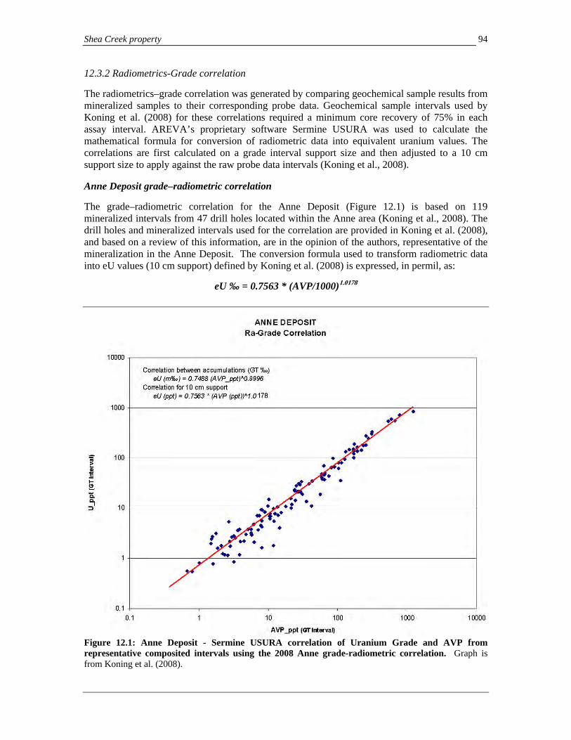
Shea Creek property 94
12.3.2 Radiometrics-Grade correlation The radiometrics–grade correlation was generated by comparing geochemical sample results from mineralized samples to their corresponding probe data. Geochemical sample intervals used by Koning et al. (2008) for these correlations required a minimum core recovery of 75% in each assay interval. AREVA’s proprietary software Sermine USURA was used to calculate the mathematical formula for conversion of radiometric data into equivalent uranium values. The correlations are first calculated on a grade interval support size and then adjusted to a 10 cm support size to apply against the raw probe data intervals (Koning et al., 2008). Anne Deposit grade–radiometric correlation The grade–radiometric correlation for the Anne Deposit (Figure 12.1) is based on 119 mineralized intervals from 47 drill holes located within the Anne area (Koning et al., 2008). The drill holes and mineralized intervals used for the correlation are provided in Koning et al. (2008), and based on a review of this information, are in the opinion of the authors, representative of the mineralization in the Anne Deposit. The conversion formula used to transform radiometric data into eU values (10 cm support) defined by Koning et al. (2008) is expressed, in permil, as:
eU ‰ = 0.7563 * (AVP/1000)1.0178
Figure 12.1: Anne Deposit - Sermine USURA correlation of Uranium Grade and AVP from representative composited intervals using the 2008 Anne grade-radiometric correlation. Graph is from Koning et al. (2008).

Shea Creek property 95
Kianna Deposit grade-radiometric correlation: The grade–radiometric correlation for the Kianna Deposit (Figure 12.2) is based on 107 mineralized intervals from 45 drill holes located within the Kianna area (Koning et al., 2008). The drill holes and mineralized intervals used for the correlation are provided in Koning et al. (2008), and based on a review of this information, are in the opinion of the authors, representative of the mineralization in the Kianna Deposit. The conversion formula used to transform radiometric data into eU values (10 cm support) defined by Koning et al. (2008) is expressed, in permil, as:
eU ‰ = 0.8706 * (AVP/1000)1.0011
Figure 12.2: Kianna Deposit - Sermine USURA correlation of Uranium Grade and AVP from representative composited intervals using the 2008 Kianna grade-radiometric correlation. Graph is from Koning et al. (2008).

Shea Creek property 96
Grade-radiometric correlation for other parts of the Shea Creek property For drill holes outside of the Anne and Kianna Deposits, including holes drilled in the Colette area, AREVA currently utilizes a general grade-radiometric coefficient of eU ‰ = 1.000 * (AVP/1000)1.0000 (E. Koning, pers. comm., 2009). Based on the conversion coefficients at Anne and Kianna, this may on average overstate the geochemical grade equivalent. Consequently, where sufficient geochemical data are available such as at Colette, or in the area between Anne and Colette, it is recommended here that customized conversion coefficients be constructed for other parts of the project area, especially if the data are to be used in any disclosure or resource estimate. 12.4 Sample Security The Shea Creek core facility is on the former Cluff Lake mine site to which only AREVA or other authorized personnel have access. As such, all on site sampling is conducted in a secure setting. The mineralized bagged samples are placed into sealed IP-3 pails, while the barren bagged samples are placed in plastic pails which are temporarily stored outside of the sample preparation room until shipped by truck to the SRC Geoanalytical Laboratories in Saskatoon, Saskatchewan (Koning et al, 2008). Samples are shipped directly in sealed containers by truck to Saskatoon, and once in the SRC laboratory are processed within laboratory facilities which are restricted to SRC personnel. The potential for tampering is limited, and could be detected by comparison to probe and scintillometer readings which are obtained independently from the geochemical results. 12.5 Quality control measures Quality control measures and procedures are addressed in Section 13.0. 12.6 Authors’ Opinion on Sampling, Preparation, Security, and Procedures In the authors’ opinions, the procedures employed at Shea Creek during sampling, shipping, sample security, analytical procedures, inter-lab assay validation, validation by different laboratory techniques (uranium ICP-MS partial, ICP-MS total and ICP-OES; uranium by DNC analysis), QA/QC protocol (see below), and use of probe data conversion comply with industry standard practices. UEX personnel, including the authors, have also directly reviewed laboratory procedures and practices on site at SRC through two laboratory audits. A significant additional level of validation of geochemical results comes from the results of downhole radiometric probe data, from which calibrated conversion factors allow cross checking, and where necessary in areas of poor core recovery, substitution for geochemical data. The authors have reviewed the probe use and methodologies, and find these and the currently utilized coefficients that were calculated in 2008 conform to industry standards, and form a reasonable estimation of uranium grade in the Kianna and Anne Deposits. Further calibration of probe coefficients for areas outside of the Anne and Kianna Deposits on the Shea Creek property is recommended where sufficient previous geochemical data is available if data are to be utilized in future disclosure or resource estimation.

Shea Creek property
97
13.0 DATA VERIFICATION (Form 43-101F1 item 16) Several levels of data verification are utilized at Shea Creek, including:
(i) internal SRC laboratory quality assurance and quality control (“QA/QC”),
(ii) comparison of the results of the different geochemical analytical techniques for uranium which are routinely received (uranium partial and total by ICP-MS, U3O8 assay by ICP-OES),
(iii) comparison to probe results, and
(iv) external laboratory check analysis of selected samples. Radiometric probes used in drill holes are regularly calibrated using the SRC gamma-probe calibration facility in Saskatoon, although repeat probe logging of the drill holes has not been done (Koning et al., 2008). As part of AREVA’s quality improvement programs, a more rigorous QA/QC program was implemented in 2006, which continues to be followed. UEX has conducted two lab audits on the primary lab, SRC Geoanalytical Laboratories, in Saskatoon, Saskatchewan. An initial lab audit was conducted on September 24, 2007 by D. Baldwin, AUSIMM and a follow up review was carried out on June 5, 2008 by D. Baldwin and the authors. The lab audit covers all aspects of the sample preparation and analytical process, as apply to all of UEX’s projects, and which are also applicable to samples submitted by AREVA as part of the Shea Creek joint venture. Minor recommendations were made regarding methodologies and equipment condition, but no deficiencies were noted. During the course of preparation of this report, the authors have reviewed and validated the data which is presented in Appendix 2 and throughout the text. All drill hole geochemical and probe composites presented here were calculated by the authors from primary data which was obtained from AREVA. 13.1 Comparison of analytical techniques Comparison of analytical pairs for 2006 and 2007 analyses at Shea Creek by ICP-MS (total and partial U) and ICP-OES (U3O8 uranium assay) is presented in scatter plots in Figure 13.1. The plots show a high degree of correlation of the individual techniques, and the lack of outliers suggest minimal evidence for any significant transcription or accidental sample substitutions. Several data points which previously lay outside tolerance were checked, and data transcription errors were identified which have now been corrected in the database (D. Quirt, pers. comm., 2009).
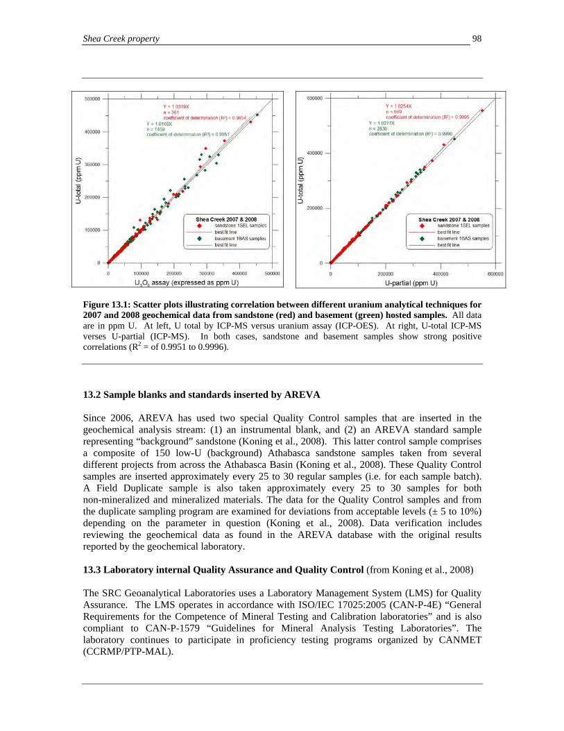
Shea Creek property 98
Figure 13.1: Scatter plots illustrating correlation between different uranium analytical techniques for 2007 and 2008 geochemical data from sandstone (red) and basement (green) hosted samples. All data are in ppm U. At left, U total by ICP-MS versus uranium assay (ICP-OES). At right, U-total ICP-MS verses U-partial (ICP-MS). In both cases, sandstone and basement samples show strong positive correlations (R2 = of 0.9951 to 0.9996). 13.2 Sample blanks and standards inserted by AREVA Since 2006, AREVA has used two special Quality Control samples that are inserted in the geochemical analysis stream: (1) an instrumental blank, and (2) an AREVA standard sample representing “background” sandstone (Koning et al., 2008). This latter control sample comprises a composite of 150 low-U (background) Athabasca sandstone samples taken from several different projects from across the Athabasca Basin (Koning et al., 2008). These Quality Control samples are inserted approximately every 25 to 30 regular samples (i.e. for each sample batch). A Field Duplicate sample is also taken approximately every 25 to 30 samples for both non-mineralized and mineralized materials. The data for the Quality Control samples and from the duplicate sampling program are examined for deviations from acceptable levels (± 5 to 10%) depending on the parameter in question (Koning et al., 2008). Data verification includes reviewing the geochemical data as found in the AREVA database with the original results reported by the geochemical laboratory. 13.3 Laboratory internal Quality Assurance and Quality Control (from Koning et al., 2008) The SRC Geoanalytical Laboratories uses a Laboratory Management System (LMS) for Quality Assurance. The LMS operates in accordance with ISO/IEC 17025:2005 (CAN-P-4E) “General Requirements for the Competence of Mineral Testing and Calibration laboratories” and is also compliant to CAN-P-1579 “Guidelines for Mineral Analysis Testing Laboratories”. The laboratory continues to participate in proficiency testing programs organized by CANMET (CCRMP/PTP-MAL).
Shea Creek property
99
The Quality Control measures carried out by the laboratory (SRC, 2007) include a minimum of one of the following measures that can be applied to each batch of samples to assure the quality of the results generated:
(i) sample preparation QC checks,
(ii) analysis of Certified Reference Standards,
(iii) analysis of in-house reference materials and standards,
(iv) traceable calibration standards for instrumentation,
(v) analysis of duplicate samples,
(vi) analysis of blind QC samples,
(vii) spiking of samples to monitor process recoveries,
(viii) proficiency testing and inter-laboratory comparisons, and
(ix) QC monitoring.
The Quality Control measures applied to all methods within the laboratory have been established to ensure that they are compliant with the requirements of ISO/IEC 17025:2005. The Quality Control measures which are applied may vary from method to method and are selected on their suitability. All Quality Control measures applied at the laboratory are checked by supervisory and Quality Assurance personnel prior to reporting results. If results are found to be outside Quality Control limits, actions are taken to ensure that the samples are reprocessed and the required quality limits are met.
Analytical blanks, replicates, and certified rock standards are systematically inserted in each group of samples and their results are reported to the client (SRC, 2007). An analytical replicate (“repeat”) is inserted after every 25 samples (i.e. one per batch). This repeat sample is a repetition of the analytical measurement from the same solution. It is not a true replicate sample with analysis of a different solution made from a different aliquot of the same sample pulp.
Certified standard materials are analyzed routinely with results for a standard appearing approximately every 15 samples. The standards used for the ICP-OES package include in-house standards CG515 and LS4, both of which are in pulp form and which are prepared in the same manner as the other samples. There is no trace of results for internal blank samples in the assay reports that we have compiled.
The authors have directly reviewed with SRC representatives these laboratory procedures, and confirm that they meet industry standards.
13.4 External laboratory check analyses
In 2007 and 2008, AREVA personnel randomly selected approximately 5% of pulps from geochemical samples collected from drill core at Shea Creek for additional analyses at SRC’s Delayed Neutron Counting (“DNC”) laboratory. This is a separate lab facility located at SRC Analytical Laboratories, 422 Downey Road, Saskatoon, Saskatchewan. The DNC method is a non-geochemical method which utilizes material from the pulps of geochemical samples, which are irradiated in a Slowpoke 2 nuclear reactor then pneumatically transferred to a counting system equipped with 6 helium-3 detectors. The proportion of delayed neutrons detected is directly related to the uranium concentration.
Results of the DNC check analyses are still being received (D. Quirt, pers. comm.., 2009). Additional future check analyses on approximately 10% of the samples split from mineralized intervals in upcoming drilling programs is recommended. DNC analyses will provide another method in addition to the uranium assay, scintillometer and probe data to validate the geochemical results.

Shea Creek property 100
14.0 ADJACENT PROPERTIES (Form 43-101F1 item 17)
As previously discussed, the northern boundary of the Shea Creek property lies 13 km to the south of the past producing Cluff Lake uranium camp, which produced 64.2 million lbs U3O8 between 1980 and 2002 (Koning and Robbins, 2006). While much of the mining infrastructure has now been reclaimed, excellent all weather road access, and a year round camp for accommodation are still retained on site. The area also has a long record of environmental study through the mining and reclamation work. Geologically, the Cluff Lake deposits have similarities to the Shea Creek mineralization and further underscore this area as a significant uranium district.
The northern portions of the Colette Deposit extend nearly to the northern boundary of the Shea Creek property with the adjacent Douglas River property. The Douglas River property is part of the Western Athabasca Projects shown on Figure 3.1 and, like Shea Creek, forms part of the UEX-AREVA joint venture in which UEX has earned a 49% interest. Geophysical surveys and drilling indicate that the Saskatoon Lake Conductor and its hosting pelitic gneiss unit continues northward onto the Douglas River property. Several widely spaced drill holes have tested the conductor on the Douglas River property. These include drill hole DGS-10, drilled 300 meters north-northwest of the Collette Deposit, which intersected uranium mineralization at the sub-Athabasca unconformity grading 0.53% eU3O8 over 3.7 meters at a vertical depth of approximately 690 meters. The mineralization consisted of sooty pitchblende and coffinite along fracture planes and within the matrix of a hematized tectonic breccia (Robbins et al., 1997b; Koning et al., 2008). The reference Robbins et al. (1997b is an assessment report available for public viewing in the offices of the Saskatchewan Ministry of Energy and Resources at 200-2101 Scarth Street, Regina, Saskatchewan. Base metal minerals such as pyrite, galena, sphalerite and arsenopyrite are associated with the mineralization. Other drill holes on line L96+00N, DGS-9 (210 m east of DGS-10) and DGS-11 (80 m west of DGS-10), display anomalous U-partial, Pb and Ni at the unconformity (Robbins et al., 1997b), which are positive geochemical indicators of potential nearby mineralization. Drill holes are widely spaced in this area and exploration potential of this area is high for extensions of Shea Creek mineralization.
The Shea Creek property is also contiguous with the Erica property to the west (Figure 3.1), which also forms part of the UEX-AREVA joint venture. Drilling of conductive features on this property have confirmed the presence of graphitic conductors with associated faults, but no mineralization has been intersected to date in the few drill holes which have been completed.
The Qualified Persons have not verified the information on adjacent properties and it is not necessarily indicative of mineralization on the property subject to the technical report.
15.0 MINERAL PROCESSING AND METALLURGICAL TESTING (Form 43-101F1 item 18)
No representative mineral processing or metallurgical testing studies have yet been completed on the Shea Creek deposits. Cazakoff and Tennant (2008) report results of a limited scoping leach trial on uranium recovery from a small sample suite of quartered drill core from the Kianna basement, Kianna unconformity, Anne basement and Anne unconformity mineralization which was performed at AREVA’s McClean Lake mining facility. Although high recoveries were obtained, this study cannot be considered representative as the selection of samples for this suite was severely skewed to intervals with highly anomalous Ni-As-Mo concentrations that are atypical of the mineralization, particularly for the Kianna composites. Future studies should be selected from suites with representative typical uranium and other elemental concentrations. Mineralogical studies (e.g. Reyx, 1995) and review of the geochemical database suggest that uranium mineralization at Shea Creek is dominantly in pitchblende with associated secondary uranium minerals and low Ni-arsenide abundance. The Shea Creek mineralization has very similar mineralogical and paragenetic characteristics to mineralization in other deposits in the region, including Cluff Lake, which have been, or are currently being mined.

Shea Creek property 101
16.0 MINERAL RESOURCE AND MINERAL RESERVE ESTIMATES (Form 43-101F1 item 19) No historical and no current N.I. 43-101 compliant mineral resource or reserve estimates have been disclosed for the Shea Creek deposits. 17.0 OTHER RELEVANT DATA AND INFORMATION (Form 43-101F1 item 20) To better define the extent, grade and continuity of uranium mineralization on the Shea Creek property, UEX and AREVA announced in April, 2007 (see UEX’s April 10, 2007 news release) the intention of exploring the area of the Kianna and Anne Deposits by underground development. This program would involve the sinking of one or two underground exploratory shafts, from which exploration drifts could be excavated to allow delineation drilling. Initial plans propose placing the first potential 950 meter deep shaft strategically between the Kianna and Anne Deposits to facilitate underground access to both deposits as well as to further test the highly prospective corridor between them. In February 2008, a scoping level study was initiated to determine the costs of this process. SNC Lavalin, McIntosh Engineering and AREVA personnel are continuing this work. UEX has indicated that studies to optimize the facilities based on field data will continue in 2009. Geotechnical and hydrogeological data collection commenced in 2007 with the drilling and instrumenting of several geotechnical drill holes in the area which include the HYD- series drill holes listed in Appendix 1. This work continued in 2008 with the drilling of a potential pilot shaft hole to a depth of 1,000 m (drill hole P-08-1), which allowed complete detailing of geotechnical and hydrogeological parameters. In addition, a large diameter (PQ) pumping hole was drilled to ascertain additional hydrogeological data. SRK Consulting is the lead consultant for this phase of work. This data will provide a basis for groundwater inflows and ground stability assessments for underground infrastructure. Environmental Impact Statement and Licensing Any construction or underground development must be preceded by the required regulatory process, the first step of which is the gathering of environmental baseline data. As previously announced (see UEX News Release, April 10, 2007), AREVA has started the necessary studies for site characterization and baseline studies. Baseline data collection and site characterization will continue in 2009 in support of the future Environmental Impact Statement. 18.0 INTERPRETATION AND CONCLUSIONS (Form 43-101F1 item 21) 18.1 Summary and discussion Exploration at the Shea Creek property both prior to, and since UEX’s involvement has successfully accomplished the objective of the discovery of new uranium mineralization, and demonstrated the high exploration potential of other areas. Since UEX’s involvement in 2004, the Kianna Deposit has been discovered and outlined, areas between Kianna and Anne have been found to contain significant mineralization, additional high grade mineralization has been intersected at the Anne Deposit, and basement mineralization has been intersected in the South Colette area. To date, drilling has identified a three kilometer strike length of the Saskatoon Lake Conductor in the northern Shea Creek property in which at least three uranium deposits are developed. Within this area, drilling has been focused in two areas in which semi-continuous mineralization have been traced at the unconformity: a) the Colette and Colette South areas, over

Shea Creek property 102
a 0.7 km strike length, and b) the Kianna to Anne Deposit areas, over a 1.1 km strike length. The area in between the Kianna and Colette Deposits, termed the 58B area, has only been sparsely drilled along its one kilometer strike length and has high potential for discovery of additional mineralization. Mineralization at Shea Creek comprises three styles, based on its position to the sub-Athabasca unconformity:
1) perched mineralization, developed up to several tens of meters above the unconformity as shallow dipping pods in zoned alteration,
2) unconformity-hosted mineralization, the most widespread style to date, which occurs as a shallow dipping, elongate lens often associated with chlorite-matrix breccias along the unconformity where southwest-dipping faults along the base of the pelitic gneiss sequence intersect the unconformity, and
3) basement-hosted mineralization, occurring as both foliation-parallel southwest dipping lenses and as discordant, east-northeast to east-west trending, steeply dipping zones which may extend for more than 200 meters below the unconformity.
Where best developed and highest grade, all three styles may be vertically stacked on top of one another, from basement mineralization below, through well developed unconformity-hosted mineralization, and perched mineralization immediately above. These stacked, better developed areas of mineralization may be localized in areas where steeply dipping, discordant east-west to northeast trending faults interact with, and intersect the foliation-parallel fault at the unconformity creating zones of high dilatancy and structural permeability. Pre-Athabasca basement structural architecture may also play an important role in localizing these higher grade areas, since where the Saskatoon Lake Conductor is offset by northeast-trending dextral mylonitic shear zones, faults localized along the conductor may step and splay as they link across the area of offset. In addition, the older shear zones themselves may be remobilized and host, or control adjacent mineralization. 18.2 Exploration potential and targets The Shea Creek property is highly prospective for the discovery of additional uranium mineralization. Several levels of exploration potential are apparent. In known deposits, potential exists to expand the dimensions of high grade pods between, or outward from previous drill holes. Even small expansions by additional drilling to pods of very high grade mineralization (e.g. >20% U3O8) that have been encountered can have a very material affect on their estimated total uranium content. Therefore, infill and nearby step-out drilling in some of these areas is recommended. Very high grades in uranium systems are often annular, and additional drill holes in the core areas of moderate grade mineralization may identify higher grade cores to some zones. Exploration potential exists for step-out drilling into open areas of mineralization, for example to expand the Kianna basement zone, and to test open mineralization down dip in the Colette area. Gaps in drilling along the main prospective corridor between Anne and Kianna, and between Kianna and Colette also have high potential for new discoveries for both mineralization at the unconformity and in the basement rocks. In these areas, modeling of the distribution and intensity of clay alteration in basement rocks, as well as the structural setting of local areas as exploration proceeds will aid in targeting new zones of basement mineralization. Enhanced coding and recording of structural features during core logging, particularly faults, mylonites,

Shea Creek property 103
mineralized veins, and banding of mineralization, may further aid in local targeting of basement mineralization in these, and other prospective areas on the property. In both the prospective three kilometer corridor in the northern part of the Shea Creek property, and other areas to the south along the Saskatoon Lake Conductor, potential may also exist for significant areas of basement mineralization which have little or no expression at the unconformity. As with the example of the Eagle Point Deposit, in the eastern Athabasca Basin, large zones of basement mineralization in extensional vein sets may develop in basement rocks along strike from mineralized zones that occur at the unconformity. These basement zones are localized along steeply dipping faults and veins that pass obliquely across the metamorphic sequence. This is the case with the numerous northeast trending, and potential east-west trending faults at Shea Creek. It implies potential for basement-hosted mineralization in other areas, such as southeast of the Anne Deposit, where broad zones of anomalous geochemistry and favorable alteration have been intersected, but no significant mineralization has yet been identified at the unconformity. In other areas on the Shea Creek property where little or no drilling has occurred, exploration is in its early stages and targets are mainly geophysical (EM conductors and resistivity). Prospective areas of low resistivity with a similar signature to the area around the Anne, Kianna and Colette Deposits occur along the Klark Lake Conductor in northwestern parts of the property. Low resistive zones lying between the Saskatoon Lake and Klark Lake Conductors also form prospective targets that could represent alteration along discordant fault zones. Expansion of resistivity surveys to other parts of the property is recommended to further identify other low resistivity targets, potentially with use of lower cost systems such as Low Temperature Superconducting Quantum Interference Device (LT SQUID), which in initial trials has shown promising results. Targets along the Colette-Anne corridor Numerous areas of high exploration potential lie along the three kilometer corridor between and including the Anne, Kianna and Colette Deposits. Some highly prospective targets with strong potential for extending mineralization and potentially discovering completely new zones, particularly in basement rocks include:
1) Basement mineralization in the Colette South area. Many intercepts of broad, lower grade mineralization are open here downdip and to the southeast, and the potential for higher grade basement foliation parallel and discordant vein/fault hosted mineralization in this area is high. The structural setting adjacent to the 8000N fault is highly favorable for further basement mineralization, and also suggests other, more east-west or east-southeast trending discordant faulting is present, as evidenced by deflections in the unconformity elevation and pelitic gneiss unit (Figure 6.5).
2) Northwest Colette: Potential for basement-hosted mineralization in the northwest Colette area associated with the east-northeast trending Colette faults. Steeply dipping, vein and fault controlled basement mineralization could lie between the current vertical drill holes, parallel to the section lines, based on the linear east-northeast trending zone of higher grade mineralization at the unconformity on section 9200N (Figure 6.5).
3) 58B area. Only 18 widely spaced drill holes test the area of the unconformity between the 7600N and 8450N faults over a strike length of 850 meters of the Saskatoon Lake Conductor. Several drill holes within this area have intersected mineralization which is open. The best results were obtained from drill hole SHE-058B, which contains both
Shea Creek property
104
unconformity- and basement-hosted mineralization, including 2.213% U3O8 over 2.60 m approximately 30 meters below the unconformity. The stacking of mineralization is characteristic of areas containing the best developed mineralization in the Anne and Kianna Deposits, and mineralization is completely open. A prospective deflection in the pelitic gneiss unit, which may represent a west-northwest trending fault, is apparent between this drill hole and mineralized drill holes SHE-103 to 103-03 to the south.
4) Kianna basement extensions. The main zone of basement mineralization at Kianna still has room for expansion west of the area of high grade basement mineralization in drill hole SHE-115-11, which contains the westernmost intercept of high grade mineralization in the Kianna basement zone. Clay alteration is still wide and extends westward here in a broad zone, which could host extensions of this mineralization, or parallel zones which may occur deeper and en echelon. Easternmost and some downdip portions of the main Kianna basement zone may also be open since drill holes are subparallel to the dip of the zone, and may pass on both sides of the zone. Drill hole SHE-114-17, which lies approximately 50 meters north of the main basement zone (Figure 8.3), also contains a significant basement intersection. This mineralization in hole SHE-114-17 could either link back to the main basement zone, or form a separate east-northeast trending and steeply dipping basement pod to the north which is still open in several directions.
5) Basement mineralization in the Kianna South area. The SHE-123 series drill holes have intersected significant basement and unconformity mineralization in this area which is associated with a zone of basement clay alteration. The alteration could extend westward to clay alteration and uranium mineralization intersected in drill hole P-08-01, over 100 meters to the west. There is potential in this area for an east-west to east-northeast trending, clay alteration hosted mineralized zone in basement rocks that is parallel to the main Kianna zone.
6) Unconformity and basement mineralization between the 7000N and 7250N faults (Figure 6.6). The area between the 7000N and 7250N faults has been sparsely drilled. Several holes have intersected significant mineralization in this area, including drill hole SHE-038A, which intersected 2.6 m grading 8.664% U3O8 at the unconformity. This mineralization is open to the northwest and southeast along strike. In addition, several drill holes have intersected basement mineralization which is low grade, but demonstrates the potential for basement-hosted mineralization here to be stacked below the higher grade unconformity style.
7) Extensions of basement mineralization, and better definition of higher grade areas at Anne: Significant basement intercepts in the northern portions of the Anne Deposit around section 6875N (Figure 6.6), like the main Kianna basement zone, may define an approximately east-west trending and steeply dipping zone of mineralization. In this area more extensive branching mineralization is observed that may follow gneissosity. The steeply dipping zone may pass westward from drill hole SHE-088 between, or beneath drill holes. Similar patterns may occur further south in the Anne Deposit, where basement mineralization may extend westward from drill hole SHE-94-1 and SHE-96-04, as well as in other areas in the southern part of the Anne Deposit.
8) The southern end of the Anne Deposit. At the southeastern end of the currently more closely spaced drilling in the Anne Deposit (south of UTM 6455000N, or grid line 6650N), the SHE-105-series drill holes have intersected a combination of basement, unconformity and perched mineralization. Most of this mineralization is lower grade, but much is open to the northwest and southeast, and may be associated with additional zones of mineralization.
Shea Creek property 105
18.3 Adequacy of drilling data density and reliability During the drilling programs at Shea Creek, in the author’s opinions based on a review of data, discussion with AREVA geologists and on site observation of data acquisition and sampling, all industry standards were followed at the time of each drilling program. Core sizes, procedures for logging and recording of core recoveries and consistent documentation of the geology provide an acceptable basis for the geological interpretation of the deposits. The quality control-quality assurance procedures and validations on the project have become more rigorous since initial drilling was conducted on the Shea Creek property in the early 1990’s as industry-wide standards evolved. However, review of core and probe data from these earlier periods shows the data to be representative, and consistent with more recent drill holes which have been completed nearby. For more recent exploration conducted on the project, the results of the additional levels of cross checking of assay techniques and confirmation with duplicate samples and probe data are industry standard and provide a high level of confidence in the sample data. Sample density and spacing in drill holes is sufficient to represent variations in grade and mineralization style. 19.0 RECOMMENDATIONS (Form 43-101F1 item 22) 19.1 Drilling program Recommended work programs on the Shea Creek property comprise a combination of a) infill and step-out drilling to further advance the deposits toward a future N.I. 43-101 compliant resource estimate, and b) exploration drilling along the prospective three kilometer corridor in the northern Shea Creek property. In addition to infill drilling in the Anne and Kianna areas, and the area between the deposits, the recommended program will allow testing of the highest priority targets listed in Section 18.2 above. Some of the targets in Section 18.2 will require further assessment, including drill core review, before drilling is planned. A drilling program of approximately 15,500 meters with six pilot holes (each 900 m average length) and 26 navigational cuts (each approximately 350 to 400 m in length) is recommended. In areas of infill and step-out drilling, many of the proposed holes could be drilled as cuts from existing pilot drill holes. Recommended drilling is as follows:
a) Infill drilling, and potentially extending principal portions of the Kianna and Anne Deposits at 20 meter drill centers for resource definition purposes (one pilot hole and approximately 9 navigational cuts), including testing of targets as listed in point (4) of Section 18.2.
b) Infill drilling of selected portions of the corridor between the Anne and Kianna Deposits containing the highest grade-thickness or greatest potential at 40 meter drill centers, for resource definition purposes (two pilot holes and approximately 12 navigational cuts) that includes testing targets listed in points (5) and (6) of Section 18.2.
c) Drilling of at least two of the outlying target areas: the 58B target as described in point (3) of Section 18.2 (one pilot hole and at least one navigational cut) and testing for further basement mineralization potential in the Colette South area (one pilot hole and at least two navigational cuts).
d) Drilling in the southeastern Anne area to test the section between the SHE-105 series drill holes and the main Anne Deposit (one pilot hole and two navigational cuts).
In some of these areas, drilling meterage could be significantly reduced, and potentially reallocated to additional drill holes, if it is possible to re-enter older pilot holes to allow wedging at depth close to these and other targets.

Shea Creek property
106
19.2 Infill sampling of existing drill core In addition to the drilling proposed above, further selective sampling of existing drill core is recommended to provide a more comprehensive geochemical database for future resource estimation. This would include:
1) sampling of previously unsampled intercepts of mineralization for which only probe data is
currently available (e.g. SHE-103 to SHE-105 series drill holes),
2) infill sampling of previously unsampled weakly radioactive intervals within mineralized zones where previously sampled mineralization meeting the compositing criteria in Appendix 2 is separated by unsampled intervals less than 5 meters in length, and
3) sampling of mineralized intervals which may have less than the 75% recovery threshold for sampling by AREVA that have not been previously sampled, if at least 0.2 meters of recovered material remains in the core box. In this case, these new geochemical results from intervals with poor core recovery can be checked against probe data and utilized if deemed representative, treated on a case by case basis, especially if core recovery is greater than 50%. In total up to 1,000 samples may need to be collected.
19.3 Budget Costs for the 2009 drilling program, including the additional sampling, are outlined in Table 19.1. AREVA would be operator of this program. Total costs are estimated at approximately C$8.26 million, of which UEX, as 49% partner, is responsible for $4.05 million. Costs are based on previous programs operated by AREVA, and include accommodation and logistical use of AREVA’s Cluff Lake camp facilities. Personnel costs below include geological staff, technicians, administrative staff as well as geophysical and engineering support.
Table 19.1: Proposed 2009 Shea Creek exploration budget (rounded to nearest $1,000)
Item Cost
AREVA personnel 1,360,000 Supplies and maintenance 160,000 Fuel 520,000 Freight 20,000 Travel and transportation 96,000 Cluff Lake camp accommodation costs 875,000 Communications and utilities 5,000 Land use 2,000 Equipment rental 70,000 Drilling costs (contractor), 15,500 m, including directional drilling costs 4,200,000
SRC laboratory analysis 200,000 Total operational costs 7,508,000
AREVA overhead/management fee (10%) 751,000 Grand Total 8,259,000
UEX Cost at 49% 4,047,000
Shea Creek property 107
20.0 REFERENCES (Form 43-101F1 item 23)
Alexander, B., Alonso, D. and Koch. R., 1994. Shea Creek Project 1994 Winter Activities and Results. Vol. I to III, COGEMA Resources Inc. Rep .#94-CND-585-01.
Alexander, B., Alonso, D. and Bingham, D., 1995. Shea Creek activities and results. Vol. I to V,
COGEMA Resources Inc. Rep. #95-CND-585-01. Alexandre, P., Kyser, T. K., Thomas, D., Polito, P., and Marlat, J., 2009. Geochronology of the
unconformity-related uranium deposits in the Athabasca Basin, Saskatchewan, Canada and their integration in the evolution of the basin. Mineralium Deposita, vol. 44, pp 41-59.
Alonso, D., Dalidowicz, F. and McElroy, R., 1992. Shea Creek Project 1992 Winter Activities and
Results. Amok Limited/Ltee. Vol. I to III, Rep. #92-CND-585-01. Ashton, K. E., Card, C. D., and van Breemen, O., 2007. Recognition of Paleoproterozoic supracrustal
rocks along the Snowbird Tectonic Zone and more evidence for mesoarchean crust in the Southern Rae Province: New TDM data from northwestern Saskatchewan. Saskatchewan Industry and Resources, Open file report 2007-22, 9 p.
Baudemont, D., 1996. Shea Creek Project. Regional Tectonics and Structural Control of Mineralization.
Report on 1995 Investigation. COGEMA Resources Inc. Rep. #96-CND-585-01. Baudemont, D., 2000. Shea Creek Project Western Athabasca. Colette Mineralized Zone –
Lithostratigraphy, Structural Geology and Perspectives. COGEMA Resources Inc. Rep. #00-CND-585-01.
Baudemont, D. and Fedorowich, J., 1996. Structural control of uranium mineralization a the Dominique-
Peter Deposit, Saskatchewan, Canada. Ecomonic Geology Vol. 91, pp. 855-874. Baudemont, D. and Lorilleux, G. 1998. Shea Creek Project – Anne Mineralized Zone. Lithostratigraphy,
Structural Geology, Hydrothermal Breccias. COGEMA Resources Inc. Rep. #98-CND-585-04. Baudemont, D., Piquard, J. P., Ey, F., and Zimmerman, J., 1993. The Sue uranium deposits,
Saskatchewan, Canada. Exploration and Mining Geology, Vol. 2, No. 3, pp. 179-202. Bell, K., 1985. The Carswell Structure uranium deposits, Saskatchewan. in The Carswell Structure
Uranium Deposits, Saskatchewan, Laine, R., Alonso, D., and Svab, M., (eds.); Geological Association of Canada, Special Paper 29, pp. 33-46.
Bickford, M.E., Collerson, K. D., and Lewry, J.F., 1994. Crustal history of the Rae and Hearne
provinces, southwestern Canadian Shield, Saskatchewan: constraints from geochronologic and isotopic data. Precambrian Research, v. 68., pp. 1-21.
Bingham, D. and Koning, E., 2003. Shea Creek Project 2003 Exploration Activities and Results.
COGEMA Resources Inc. Rep. #03-CND-585-01. Brouand, M., Cuney, M., and Deloule E., 2002. Le Plutonisme Hyperpotassique de socle sous la partie
ouest du Bassin Athabasca, nord Saskatchewan, Canada. Abstract volume, RST 2002 9-12 April Nantes, France, p. 76.
Card, C., 2001. Basement rocks to the western Athabasca Basin in Saskatchewan. In: Summary of
Investigations 2001, Volume 2, Saskatchewan Geological Survey, Saskatchewan Energy and Mines, Misc. Rep. 2001-4-2.
Shea Creek property 108
Card, C. D., 2002. New investigations of basement to the western Athabasca Basin. in Summary of Investigations 2002, Volume 2, Saskatchewan Geological Survey, Saskatchewan Energy and Mines, Misc. Rep. 2002-4-2, 17 p.
Card, C. D. 2006. Basement control on uranium mineralization in the western Athabasca Basin and the
region’s pre- and post-Athabasca Group deformational history. CIM Geological Society 2006 Field Conference: Athabasca deposits and analogues, June 13 2006, extended abstract.
Card, C. D., Pana, D., Stern, R. A., and Rayner, N., 2007a. New insights into the geological history of
the basement rocks to the southwestern Athabasca Basin, Saskatchewan and Alberta. in EXTECH IV: Geology and uranium EXploration TECHnology of the Proterozoic Athabasca Basin, Saskatchewan and Alberta. C.W. Jefferson and G. Delaney (eds.). Geological Survey of Canada, Bulletin 588, pp. 119-133.
Card, C., Pana, D., Portella, P., Thomas, D., and Annesley, I. 2007b. Basement rocks to the Athabasca
Basin, Saskatchewan and Alberta. in EXTECH IV: Geology and uranium EXploration TECHnology of the Proterozoic Athabasca Basin, Saskatchewan and Alberta. C.W. Jefferson and G. Delaney (eds.). Geological Survey of Canada, Bulletin 588, pp. 69-87.
Cazakoff, D., and Tennant, D., 2008. Shea Creek – Scoping leach trials. Internal AREVA report, 17 p.
plus appendices. Clauer, N., Ey, F., and Gauthier-Lafaye, F., 1985. K-Ar dating of different rock types from the Cluff
Lake uranium ore deposits, Saskatchewan, Canada. in The Carswell Structure Uranium Deposits, Saskatchewan, Laine, R., Alonso, D., and Svab, M., (eds.); Geological Association of Canada, Special Paper 29, pp. 47-54.
Collier, B., Yeo, G., Long, D., Robbins, J., and Koning, E., 2001. Preliminary report on the stratigraphy
of the Athabasca Group in the vicinity of the Shea Creek Project, southwestern Athabasca Basin, Saskatchewan; in Summary of Investigations 2001, Volume 2, Saskatchewan Geological Survey, Saskatchewan Energy and Mines, Misc. Rep. 2001-4.2, CD B, pp. 266-271.
Cumming, G. L., and Krstic, D., 1992. The age of unconformity-related uranium mineralization in the
Athabasca Basin, northern Saskatchewan. Canadian Journal of Earth Science, Vol. 29, pp. 1623-1639. Dalidowicz, F., 1991. Shea Creek Project – Report on 1991 Ground Geophysical Surveys. Amok
Limited/Ltee. Vol. I to II, Rep. #91-CND-585-03. Dalidowicz, F., 1993. Shea Creek Project – Report on 1993 Ground Geophysical Surveys. Vol. I to II,
COGEMA Resources Inc. Rep. #93-CND-585-03. Eaton, D. W., and Hope, J., 2003. Structure of the crust and upper mantle of the Great Slave Lake shear
zone, northwestern Canada, from teleseismic analysis and gravity modeling. Canadian Journal of Earth Science v. 40, pp. 1203-1218.
Fayek, M., Harrison, T. M., Ewing, R. C., Grove, M., and Coath, C. D., 2002. O and Pb isotope
analyses of uranium minerals by ion microprobe and U-Pb ages from the Cigar Lake deposit; Chemical Geology, v. 185, pp. 205-225.
Flotte, N., 2006. Kianna area, Shea Creek Project – Map, sections and structural interpretation of
mineralization. AREVA Resources Inc. Rep. #06-CND-585-02. Hanmer, S., 1997. Geology of the Striding-Athabasca Mylonite Zone, northern Saskatchewan and
southeastern District of Mackenzie, Northwest Territories. Geological Survey of Canada Bulletin 501, 92 p.
Shea Creek property 109
Hoeve, J. and Sibbald, T. I. I., 1978. On the Genesis of Rabbit Lake and Other Unconformity-Type Uranium Deposits Northern Saskatchewan, Canada; Economic Geology, v. 73, pp. 1451-1473.
Hoeve, J. and Quirt, D. H., 1984. Mineralization and Host Rock Alteration in Relation to Clay Mineral
Diagenesis and Evolution of the Middle-Proterozoic Athabasca Basin, Northern Saskatchewan, Canada; Saskatchewan Research Council, Technical Report, No. 187, 187 p.
Hoeve, J., and Quirt, D. H., 1985. A stationary redox front as a critical factor in the formation of high-
grade, unconformity type uranium ores in the Athabasca Basin, Saskatchewan, Canada. Bulletin Mineralogique, v. 110, pp. 157-171.
Hoffman, P. F., 1988. United plates of America, the birth of a craton: Early Proterozoic assembly and
growth of Laurentia; Annual Review Earth Planetary Science, v. 16, pp. 543-603. Jefferson, C., Thomas, D. J., Gandhi, S. S., Ramaekers, P., Delaney, G., Brisbin, D., Cutts, C.,
Portella, P., and Olson, R. A., 2007. Unconformity associated uranium deposits of the Athabasca Basin, Saskatchewan and Alberta. Geological Survey of Canada, Bulletin 588, pp. 23-67.
Koch, R., 1990. Shea Creek Project – GEOTEM Airborne Electromagnetic and Magnetic Surveys. Shea
Creek Area, Saskatchewan for Amok Limited/Ltee. Volume I to II, Rep. #90- CND-585-01. Koch, R., 2003. A Report on MEGATEM Airborne EM and Magnetic Surveys Over Erica, Alexandra,
Shea Creek and Douglas River Projects – December 2003. COGEMA Resources Inc. Rep. #02-CND-975-01.
Koning, E. and Robbins, J., 2006. The Cluff Lake Deposits West Athabasca Basin, Saskatchewan,
Canada; In: 2006 CIM Field Conference, Uranium: Athabasca Deposits and Analogues (Field Trip 3) - CIM Society, Saskatoon Section Sept. 13 – 14, 2006.
Koning, E., Revering C., Robbins, J., and Quirt D., 2008. Shea Creek Uranium Project, Northern
Mining District Saskatchewan NTS Map areas 74K/3 and 74K/4. AREVA Resources Inc. Rep. #07-CND-585-04.
Laine, R., 1985. Conclusion: The Carswell Uranium Deposits – An Example of not so Unique
Unconformity-Related Uranium Mineralization; in The Carswell Structure Uranium Deposits, Saskatchewan, Laine, R., Alonso, D., and Svab, M., (eds.); Geological Association of Canada, Special Paper 29, pp. 225-230.
Laine, R., 1986. Uranium deposits of the Carswell structure. in Uranium deposits of Canada, E. L. Evans
(ed.). Canadian Institute of Mining and Metallurgy, Special Volume 33, pp. 155-169. Lewry, J.F., and Sibbald, T. I. I., 1980. Thermotectonic evolution of the Churchill Province in northern
Saskatchewan. Tectonophysics, v. 68, pp. 45-82. Lorilleux, G., Jebrak, M., Cuney, M., and Baudemont, D., 2002. Polyphase hydrothermal breccias
associated with unconformity-related uranium mineralization (Canada): from fractual analysis to structural significance. Journal of Structural Geology v. 24, pp. 323-338.
Mahan, K. H., Williams, M. L., and Baldwin, J. A., 2003. Contractional uplift of deep crustal rocks
along the Legs Lake shear zone, western Churchill Province, Canadian Shield. Canadian Journal of Earth Science v. 40, pp. 1085-1110.
McCready, K., 2007. U3O8 Method Summary. SRC Geoanalytical Laboratories, 2 p.
Shea Creek property 110
McDonough, M. R., McNicoll, V. J., Schetselaar, E. M., and Grover, T. W., 2000. Geochronological and kinematic constraints on crustal shortening and escape in a two-sided oblique-slip collisional and magmatic zone, northeastern Alberta. Canadian Journal of Earth Science, v. 37, pp. 1549-1573.
Modeland, S., Robbins, J., and Koning, E., 2008. Shea Creek Project (South Area) - Exploration
Activities and Results. Field work: February to May 2007. Vol. I of I, AREVA Resources Canada Inc. Rep. #07-CND-585-02.
Munholland, P., Lee, G., Chapman, G. and Alonso, D., 1996. Shea Creek Project Activities and Results.
Vol. I to IV, COGEMA Resources Inc. Rep. #96-CND-585-02. Mysyk, W. K. and McMullen, K. J., 1996. Petrographic Report on Selected Drill-Core Samples: Drill
Hole SHE-34 to SHE-49, Shea Creek Project , Western Athabasca, Northwestern Saskatchewan in Munholland, P., Lee, G., Chapman, G. and Alonso, D., (1996). Shea Creek Project Activities and Results. Vol. IV, COGEMA Resources Inc. Rep. #96-CND-585-02.
Moriceau, R., 1997. Shea Creek and Douglas River Projects 1997. Structural Study of Drill Holes.
COGEMA Resources Inc. Rep. #97-CND-585-03. Nimeck, G., 2005. Shea Creek and Douglas River Projects – 2005 Ground Geophysical Surveys.
COGEMA Resources Inc. Rep. #05-CND-585-01. Nimeck, G., 2006. Western Athabasca Projects – A Report on FALCON® Airborne Gravity Gradiometer
Surveys over the West Athabasca Projects. AREVA (COGEMA Resources Inc.). Rep. #05-CND-585-03.
Nimeck, G., and Koch, R., 2008. A progressive geophysical exploration strategy at the Shea Creek
uranium deposit. in The Leading Edge, January 2008, pp. 52-63. Pacquet, A., Reyx, J., 1995. Shea Creek 1995 Report Activities and Results, Vol. V, Appendix 4
COGEMA Resources Inc. Metallographic and Petrographic Report on Mineralized Zones and Halos. Pagel, M. and Svab, M., 1985. Petrographic and geochemical variations within the Carswell Structure
metamorphic core and their implications with respect to uranium mineralization. Edited by R. Laine, D. Alonso and M. Svab. The Carswell Structure Uranium Deposits, Saskatchewan. G.A.C. Special Paper 29. pp. 55-70.
Pagel, M., Wheatley, K., and Ey, F., 1985. The Origin of the Carswell Structure; in The Carswell
Structure Uranium Deposits, Saskatchewan, Laine, R., Alonso, D., and Svab, M., (eds.); Geological Association of Canada, Special Paper 29, pp. 213-224.
Pana, D., Creaser, R. A., Muehlenbachs, K., and Wheatley, K., 2007. Basement geology in the Alberta
portion of the Athabasca Basin: context for the Maybelle River area. in EXTECH IV: Geology and uranium EXploration TECHnology of the Proterozoic Athabasca Basin, Saskatchewan and Alberta. C.W. Jefferson and G. Delaney (eds.). Geological Survey of Canada, Bulletin 588, pp. 135-153.
Quirt, D.H., 2002. Geochemical Data Review and Analysis: COGEMA Resources Inc. Shea Creek
Project. Saskatchewan Research Council, Publication No. 10400-01C02, 74 p. plus Appendices. Ramaekers, P., Jefferson, C. W., Yeo, G.M., Collier, B., Long, D. G. F, Drever, G., McHardy, S.,
Jiricka, D., Cutts, C., Wheatley, K., Catuneanu, O., Bernier, S., Kupsch, B., and Post, R.T., 2007. Revised geological map and stratigraphy of the Athabasca Group, Saskatchewan and Alberta. in EXTECH IV: Geology and uranium EXploration TECHnology of the Proterozoic Athabasca Basin, Saskatchewan and Alberta. C.W. Jefferson and G. Delaney (eds.). Geological Survey of Canada, Bulletin 588, pp. 155-191.
Shea Creek property 111
Reddy, K., Modeland, S., Carroll, J., Robbins, J. and Koning, E., 2007. Shea Creek Project - Exploration Activities and Results. Field work: September to December 2006. Vol. I of I, AREVA Resources Canada Inc. Rep. #06-CND-585-03.
Rhys, D. A., 2002. Geological Report on the Hidden Bay Property, Wollaston Lake Area, Northern
Saskatchewan, report prepared for UEX Corporation by Panterra Geoservices Inc., 84 p. Filed on SEDAR.
Rhys, D. A., Horn, L., Baldwin, D. and Eriks, R. S., 2008. Technical Report on the Geology of, and
Drilling Results from, the Horseshoe and Raven Uranium Deposits, Hidden Bay Property, Northern Saskatchewan, 43-101 Report prepared for UEX Corporation, 161 p. Filed on SEDAR.
Rhys, D. A., and Ross, K. V., 1999. Structural setting and controls on uranium mineralization, Collins-
Bay Rabbit Lake fault system, Wollaston Lake to Thorburn Lake, northern Saskatchewan. Panterra Geoservices Inc., consulting report for Cameco Corporation, 278 p.
Robbins, J., 2005. Shea Creek Project - Exploration Activities and Results. Field work: September to
December 2004. Vol. I of I, COGEMA Resources Inc. Rep. #04-CND-585- 02. Robbins, J., Lee, G., Chapman, G. and Koning, E., 1997a. Shea Creek Project, Activities and Results.
Vol. I to IV, COGEMA Resources Inc. Rep. #97-CND-585-01. Robbins, J., Bzdel, L., Chapman, G., Lee, G., Koning, E., 1997b. COGEMA Resources INC., Douglas
River Project 1997 Exploration Activities and Results. 35 p. Robbins, J., Bzdel, L., Lee, G., Balzer, S. and Koning, E., 1998. Shea Creek Project, Activities and
Results. Vol. I to III, COGEMA Resources Inc. Rep. #98-CND-585-2. Robbins, J. and Koning, E., 2006. Shea Creek Project - Exploration Activities and Results. Field work:
April to September 2005. Vol. I of I, COGEMA Resources Inc. Rep. #05-CND-585-02. Robbins, J., Koning, E. and Chapman. G., 1999. Shea Creek Project, Activities and Results. Vol. I to II,
COGEMA Resources Inc. Rep. #99-CND-585-06. Robbins, J., Koning, E. and Chapman, G., 2000. Shea Creek Project, Annual Report. Vol. I to II,
COGEMA Resources Inc. Rep. #00-CND-585-10. Robbins, J., Modeland, S., Carroll, J. and Koning, E., 2007. Shea Creek Project - Exploration Activities
and Results. Field work: January to June 2006. Vol. I of I, AREVA Resources Canada Inc. Rep. #06-CND-585-02.
Robbins, J. and Williamson, A., 2004. Shea Creek Project - Exploration Activities and Results. Field
work: February to March 2004. Vol. I of I, COGEMA Resources Inc. Rep. #04-CND-585-01. Ruzicka, V., 1996. Unconformity-associated uranium. in Geology of Canadian mineral deposit types, ed.
O.R. Eckstand, W.D. Sinclair and R.I. Thorpe, Geological Survey of Canada, Geology of Canada, no. 8, pp. 197-210.
Scott, B.P., 1985. Geology of the upper Clearwater River area. Saskatchewan Energy and Mines, Open
File Report 85-2, 26 p. Sopuck, V. J., de Carle, A., Wray, E. M., and Cooper, B., 1983. Application of lithogeochemistry to the
search for unconformity-type uranium deposits in the Athabasca Basin. in Uranium Exploration in Athabasca Basin, Saskatchewan, Canada, ed. E.M. Cameron, Geological Survey of Canada, Paper 82-11, pp. 191-205.
Shea Creek property
112
Stern, R.A., Card, C. D., Pana, D., and Rayner, N., 2003. SHRIMP U-Pb ages of granitoid basement rocks of the southwestern part of the Athabasca Basin, Saskatchewan and Alberta. Radiogenic Age and Isotopic Studies: Report 16, Geological Survey of Canada, Current Research 2003-F3, 20 p.
SRC, 2006. Geoanalytical Laboratories fee schedule 2006. Saskatchewan Research Council, Saskatoon,
Saskatchewan, 17 p. SRC, 2007. Geoanalytical Laboratories fee schedule 2007. Saskatchewan Research Council, Saskatoon,
Saskatchewan, 38 p. Tona, F., Alonso, D. and Svab, M., 1985. Geology and Mineralization in the Carswell Structure – A
General Approach. Edited by R. Laine, D. Alonso and M. Svab. The Carswell Structure Uranium Deposits, Saskatchewan. G.A.C. Special Paper 29. pp. 1-18.
Tourigny, G., 2001. Structural Control and Emplacement of Uranium Mineralization at the Sue C Pit
Deposit: Sask. Geol. Survey Summ. Invest. 2001, Vol. 2, CD-ROM.

Shea Creek property 113
Dates and Signatures page
Name of Report:
Technical Report on the Shea Creek property, Northern Saskatchewan
Commissioned by:
UEX Corporation
SIGNED April 3, 2009
David Rhys Date SIGNED April 3 2009
Leo Horn Date SIGNED April 3, 2009
R. Sierd Eriks Date

Shea Creek property 114
Certificates of Qualified Persons

Shea Creek property 115
David Alan Rhys 14180 Greencrest Drive, Surrey, B.C. V4P 1L9
Certificate of Author
I, David A. Rhys, P. Geo., as an author of this report, titled “Technical Report on the Shea Creek property, Northern Saskatchewan”, prepared for UEX Corporation and dated April 3, 2009, do hereby certify that: 1. I am a consulting geologist employed by Panterra Geoservices Inc. at 14180 Greencrest Drive,
Surrey, British Columbia, Canada. 2. I am a member in good standing of the Association of Professional Engineers and Geoscientists of
British Columbia and the Association of Professional Geoscientists of Ontario. 3. I am a graduate of the University of British Columbia with a B.Sc. (1989) and a M.Sc. (1993) in
geology. 4. I have practiced my profession continuously since graduation in 1989, and have been involved in
mineral exploration and mine geology evaluation in Canada, Australia, Mexico, Russia, China, U.S.A., New Zealand, Tanzania, Ecuador and Peru.
5. I am president of Panterra Geoservices Inc., a geological consulting firm incorporated in the
Province of British Columbia. 6. As a result of my experience and qualification, I am a qualified person as defined in N.I. 43-101. 7. I am not independent of the issuer applying the test set out in section 1.4 of N.I. 43-101. 8. The foregoing report is based on my personal knowledge of the geology of the property gained
through on site investigation of diamond drill core, and review of exploration results and documentation. I last visited the project area between July 28 and August 8, 2008.
9. Prior to the July 28 to August 8, 2008 evaluation program, I briefly visited the project area on
several occasions between 2006 and 2008 including a site visit on March 28, 2008. All of the earlier trips involved discussions of exploration results with AREVA personnel, and brief examinations of representative drill core.
10. I have read N.I. 43-101 and Form 43-101F1, and the technical report has been prepared in
compliance with both. 11. As of the date of this certificate, to the best of my knowledge, information and belief, the
technical report contains all scientific and technical information that is required to be disclosed to make the technical report not misleading.
12. I am responsible for preparation of Sections 1 to 19 of this report. Dated at Vancouver, British Columbia, this 3rd day of April, 2009. SIGNED “David Rhys” (signed and sealed) David Rhys, M.Sc., P. Geo Panterra Geoservices Inc.

Shea Creek property 116
Leo S. Horn Suite 1605 – 488 Helmcken Street, Vancouver, BC, V6B 6E4, Canada
Certificate of Author
I, Leo S. Horn, MAusIMM, as an author of this report, titled “Technical Report on the Shea Creek property, Northern Saskatchewan”, prepared for UEX Corporation and dated April 3, 2009, do hereby certify that: 1. I am a senior project geologist with UEX Corporation with its principal office at Suite 1007 – 808
Nelson Street, Vancouver, BC, V6Z 2H2, Canada 2. I am a member in good standing of the Australian Institute of Mining and Metallurgy (#991541) in
Australia. 3. I am a graduate of the University of Western Australia with a Bachelor of Science degree in
Geology and Geomorphology (2001) and Bachelor of Science (Honours) (2002). 4. I have 8 years of experience in exploration geology, which includes 4 years directly related to
uranium mineralization. 5. As a result of my experience and qualification, I am a qualified person as defined in the N.I. 43-
101. 6. I am not independent of the issuer applying the test set out in section 1.4 of N.I. 43-101. 7. The foregoing report is based on my personal knowledge of the geology of the property gained
through on site investigation of diamond drill core, and review of exploration results and documentation. I last visited the project area between July 28 and August 8, 2008.
8. Prior to the July 28 to August 8, 2008 evaluation program, I visited the site on March 28, 2008.
This visit involved discussions of exploration results with AREVA personnel, and brief examinations of representative drill core.
9. I have read N.I. 43-101 and Form 43-101F1, and the technical report has been prepared in
compliance with both. 10. As of the date of this certificate, to the best of my knowledge, information and belief, the
technical report contains all scientific and technical information that is required to be disclosed to make the technical report not misleading.
11. I am responsible for Sections 6 to 9 of this report. Dated at Vancouver, British Columbia, this 3rd day of April, 2009. SIGNED “Leo Horn” (signed and sealed) Leo S. Horn, B.Sc. (Hons.), MAusIMM Senior Geologist, UEX Corporation

Shea Creek property
117
R. Sierd Eriks 295 Huckleberry Lane, Qualicum Beach, B.C. V9K 2N3
Certificate of Author
I, R. Sierd Eriks, P. Geo., as an author of this report, titled “Technical Report on the Shea Creek property, Northern Saskatchewan”, prepared for UEX Corporation and dated April 3, 2009, do hereby certify that: 1. I am the Vice President of Exploration, employed by UEX Corporation with its principal office at
Suite 1007 – 808 Nelson Street, Vancouver, BC, V6Z 2H2, Canada. 2. I am a member in good standing of the Association of Professional Engineers and Geoscientists of
Saskatchewan and Manitoba. 3. I am a graduate of Boston University with a B.A. (1976) in geology. 4. I have practiced my profession continuously since 1980, and have been involved in mineral
exploration in Canada. 5. As a result of my experience and qualification, I am a qualified person as defined in N.I. 43-101. 6. I am not independent of the issuer applying the test set out in section 1.4 of N.I. 43-101. 7. My contributions to the foregoing report are based review of exploration results and
documentation. I last visited the project area on August 8, 2008. 8. Prior to my visit on August 8, 2008, I visited the site on March 28, 2008. This visit involved
discussions of exploration results with AREVA personnel, and brief examinations of representative drill core.
9. I have read N.I. 43-101 and Form 43-101F1, and the technical report has been prepared in
compliance with both. 10. As of the date of this certificate, to the best of my knowledge, information and belief, the
technical report contains all scientific and technical information that is required to be disclosed to make the technical report not misleading.
11. I contributed to the preparation of sections 1 to 5 and 18 to 19 of this report. Dated at Vancouver, British Columbia, this 3rd day of April, 2009. SIGNED “R. Sierd Eriks” (signed and sealed) R. Sierd Eriks, B.A., P. Geo. Vice-President, Exploration UEX Corporation
Shea Creek property
APPENDIX 1:
List of drill hole collar coordinates, azimuths and lengths, 1992-2008 drilling on the Shea Creek property

DDH NAME Year drilled Hole type End Of Hole Depth to Coring Length Wedge Depth Azimuth Dip Collar UTM East Collar UTM N Collar elevation Location X_GRIDLINE Y_GRIDLINE(pilot/cut) Depth Unconformity or (m ASL) Area
(metres) (metres) Coring DepthSHE-001 1992 Hole lost 335.0 Hole lost 335.0 0.0 -90.0 594545.00 6433685.00 506.0 Shea South 44+00E S gridSHE-001B 1992 Pilot 517.0 406.40 517.0 0.0 -90.0 594550.84 6433682.08 506.0 Shea South 44+15E S gridSHE-002 1992 Pilot 757.0 698.80 757.0 0.0 -90.0 588673.56 6453431.79 375.9 SE of Anne 20+36E L0+00NSHE-003 1992 Pilot 812.0 782.90 812.0 0.0 -90.0 591650.28 6451063.78 411.0 SE of Anne 96+50E L0+00N
SHE-004 1994 Pilot 761.0 716.70 761.0 0.0 -90.0 587129.73 6455105.12 355.8 Anne 3+43W L68+00NSHE-005 1994 Pilot 736.0 691.40 736.0 0.0 -90.0 587691.27 6454514.70 359.4 SE of Anne 14+10E L60+00NSHE-006 1994 Pilot 746.0 692.20 746.0 0.0 -90.0 588236.01 6453905.62 380.2 SE of Anne 0+25E L52+00NSHE-007 1994 Pilot 745.0 719.60 745.0 0.0 -90.0 592526.09 6446630.99 420.0 South Shea* 128+00E L0+00NSHE-008 1994 Pilot 675.0 641.40 675.0 0.0 -90.0 594773.31 6440606.91 476.0 South Shea 43+00E L0+00NSHE-009 1994 Hole lost 655.0 Hole lost 655.0 0.0 -90.0 585715.12 6442737.76 418.0 South Shea* 49+50E L0+00NSHE-010 1994 Hole lost 198.0 Hole lost 198.0 0.0 -90.0 588792.00 6452843.00 375.0 SE of Anne 0+35E L40+04NSHE-010A 1994 Pilot 818.0 733.20 818.0 0.0 -90.0 588792.53 6452843.33 375.7 SE of Anne 0+27W L40+04NSHE-011 1994 Pilot 737.0 729.10 737.0 0.0 -90.0 587200.76 6455145.93 365.3 Anne 2+59W L67+98NSHE-012 1994 Pilot 827.0 709.50 827.0 0.0 -90.0 587070.77 6455066.15 376.4 Anne 4+18W L68+00NSHE-013 1994 Pilot 804.5 736.90 804.5 0.0 -90.0 586999.68 6455499.13 373.1 Kianna South 2+50W L72+00NSHE-014 1994 Pilot 803.0 706.80 803.0 0.0 -90.0 587004.43 6455033.66 380.9 Anne 4+93W L68+00NSHE-015 1994 Hole lost 40.0 Hole lost 40.0 0.0 -90.0 586932.38 6455449.86 368.2 Kianna South 3+30W L71+97NSHE-015A 1994 Pilot 794.0 723.90 794.0 0.0 -90.0 586932.38 6455449.86 368.2 Kianna South 3+30W L71+97N
SHE-016 1995 Pilot 800.0 723.20 800.0 0.0 -90.0 587100.10 6455088.33 367.3 Anne 3+80W L68+00NSHE-017 1995 Pilot 824.0 728.00 824.0 0.0 -90.0 586897.20 6455431.38 378.0 Kianna South 3+70W L72+00NSHE-018 1995 Pilot 827.0 721.30 827.0 0.0 -90.0 586862.04 6455411.38 384.5 Kianna South 4+10W L72+00NSHE-019 1995 Pilot 821.0 731.10 821.0 0.0 -90.0 586526.59 6456149.07 361.3 58B 3+36W L80+08NSHE-020 1995 Pilot 777.0 697.20 777.0 0.0 -90.0 588600.69 6453407.62 381.7 SE of Anne 20+16E BL0+00NSHE-021 1995 Pilot 770.0 703.50 770.0 0.0 -90.0 588750.22 6453457.65 373.5 SE of Anne 21+76E L0+00NSHE-022 1995 Pilot 833.0 740.70 833.0 0.0 -90.0 589011.34 6452046.33 370.7 SE of Anne 2+35W L32+00NSHE-023 1995 Pilot 761.0 743.20 761.0 0.0 -90.0 586107.23 6456825.83 374.6 Collette 3+65W L88+00NSHE-024 1995 Pilot 782.0 701.90 782.0 0.0 -90.0 587628.40 6454472.60 377.3 SE of Anne 0+53E L40+00NSHE-025 1995 Pilot 821.0 744.20 821.0 0.0 -90.0 586073.24 6456806.12 373.4 Collette 4+05W L88+00NSHE-026 1995 Pilot 821.0 727.60 821.0 0.0 -90.0 586459.05 6456103.84 384.9 Collette 4+21W L88+00NSHE-027 1995 Pilot 841.0 730.70 841.0 0.0 -90.0 586003.75 6456766.42 372.3 Collette 4+85W L88+00NSHE-028 1995 Pilot 759.0 710.20 759.0 0.0 -90.0 587404.02 6454804.02 364.6 Anne 2+50W L64+00NSHE-029 1995 Pilot 776.0 696.70 776.0 0.0 -90.0 588931.66 6452920.26 374.2 SE of Anne 1+33E L40+00NSHE-030 1995 Pilot 785.0 679.90 785.0 0.0 -90.0 587335.13 6454761.01 359.8 Anne 3+30W L64+00NSHE-031 1995 Pilot 771.0 683.80 771.0 0.0 -90.0 589066.07 6452997.07 373.6 SE of Anne 2+93E L40+00NSHE-032 1995 Hole lost 50.0 Hole lost 50.0 0.0 -90.0 586795.40 6455369.21 379.6 Kianna South 4+90W L71+96NSHE-032B 1995 Pilot 917.0 710.30 917.0 0.0 -90.0 586795.40 6455369.21 379.6 Kianna South 4+90W L71+96NSHE-033 1995 Pilot 827.0 706.40 827.0 273.0 -89.3 586724.76 6455334.19 383.7 Kianna South 5+70W L72+00N
SHE-034 1996 Hole lost 36.0 Hole lost 36.0 360.0 -90.0 586072.38 6456805.80 373.5 Collette 4+07W 88+00NSHE-034A 1996 Pilot 842.0 741.20 842.0 360.0 -90.0 586072.38 6456805.80 373.5 Collette 4+07W 88+00NSHE-035 1996 Pilot 782.0 703.20 782.0 360.0 -90.0 587156.64 6455004.47 360.1 Anne 3+80W 67+00NSHE-036 1996 Pilot 796.0 716.00 796.0 360.0 -90.0 587048.06 6455167.30 369.9 Anne 3+79W 69+00NSHE-037 1996 Pilot 785.0 723.90 785.0 360.0 -90.0 586989.97 6455254.59 368.8 Anne 3+83W 70+00NSHE-038 1996 Hole lost 143.0 Hole lost 143.0 285.0 -88.4 586931.00 6455344.00 373.0 Kianna South 3+92W 71+00NSHE-038A 1996 Pilot 824.0 710.00 824.0 223.0 -88.9 586931.20 6455343.06 373.1 Kianna South 3+92W 71+00NSHE-039 1996 Pilot 527.0 415.10 527.0 360.0 -90.0 594604.93 6433671.32 506.0 Shea South 44+70E S gridSHE-040 1996 Hole lost 59.0 Hole lost 59.0 15.0 -88.9 587031.07 6455158.30 378.2 Anne 4+02W 69+02NSHE-040A 1996 Pilot 794.0 724.90 794.0 15.0 -88.9 587031.07 6455158.30 378.2 Anne 4+02W 69+02NSHE-041 1996 Hole lost 524.0 Hole lost 524.0 360.0 -90.0 597971.71 6432993.53 545.0 Shea South 79+00E S gridSHE-042 1996 Pilot 833.0 707.40 833.0 360.0 -90.0 586922.04 6455216.14 380.4 Anne 4+63W 70+00NSHE-043 1996 Pilot 779.0 716.40 779.0 86.0 -89.8 586998.94 6455134.90 381.9 Anne 4+42W 69+00NSHE-044 1996 Pilot 710.0 707.00 710.0 360.0 -90.0 586956.26 6455235.71 375.2 Anne 4+23W 70+00NSHE-045 1996 Pilot 820.0 733.60 820.0 345.0 -89.6 586037.72 6456785.76 373.1 Collette 4+45W 88+00NSHE-046 1996 Pilot 777.0 716.40 777.0 275.0 -89.3 586973.99 6455245.29 371.9 Anne 4+02W 70+00NSHE-047 1996 Hole lost 16.0 Hole lost 16.0 8.0 -89.5 586497.46 6456120.86 367.0 58B 3+76W 79+97NSHE-047A 1996 Pilot 793.0 723.00 793.0 8.0 -89.5 586497.46 6456120.86 367.0 58B 3+76W 79+97NSHE-048 1996 Pilot 814.0 716.50 814.0 14.0 -89.5 586947.05 6455352.78 366.7 Kianna South 3+72W 71+00NSHE-049 1996 Pilot 752.0 706.60 752.0 120.0 -89.8 587181.31 6455019.40 353.2 Anne 3+50W 67+00NSHE-050 1996 Pilot 793.0 723.30 793.0 150.0 -89.9 586879.69 6455421.47 382.1 Kianna South 3+90W 72+00N
SHE-051 1997 Pilot 809.0 728.10 809.0 59.0 -89.8 585747.60 6457077.72 365.2 Collette 5+50W 92+00NSHE-052 1997 Pilot 817.0 713.60 817.0 315.0 -89.5 585675.88 6457035.74 366.5 Collette 6+30W 92+00NSHE-053 1997 Pilot 832.0 720.50 832.0 67.0 -89.5 586695.87 6455775.95 359.7 Kianna 3+78W 76+0NSHE-054 1997 Pilot 791.0 714.90 791.0 19.0 -89.3 585611.52 6457000.66 373.1 Collette 7+10W 92+00N

DDH NAME Year drilled Hole type End Of Hole Depth to Coring Length Wedge Depth Azimuth Dip Collar UTM East Collar UTM N Collar elevation Location X_GRIDLINE Y_GRIDLINE(pilot/cut) Depth Unconformity or (m ASL) Area
(metres) (metres) Coring DepthSHE-055 1997 Pilot 833.0 710.30 833.0 329.0 -88.9 586624.63 6455734.84 375.1 Kianna 4+64W 76+00NSHE-056 1997 Pilot 827.0 737.90 827.0 0.0 -90.0 586270.73 6456454.92 367.2 58B 4+10W 84+00NSHE-057 1997 Pilot 863.0 722.70 863.0 319.0 -89.8 586199.73 6456414.49 368.8 58B 4+90W 84+00NSHE-058 1997 Hole lost 26.0 Hole lost 26.0 0.0 -90.0 586340.86 6456269.62 366.1 58B 4+25W 82+00NSHE-058A 1997 Hole lost 218.0 Hole lost 218.0 0.0 -90.0 586340.86 6456269.62 366.1 58B 4+25W 82+00NSHE-058B 1997 Pilot 846.0 723.30 846.0 0.0 -90.0 586340.86 6456269.62 366.1 58B 4+25W 82+00NSHE-059 1997 Pilot 816.0 715.90 816.0 17.0 -89.6 585645.04 6457018.47 368.8 Collette 6+70W 92+00NSHE-060 1997 Pilot 806.0 724.50 806.0 182.0 -89.8 585713.94 6457057.88 370.8 Collette 5+90W 92+00NSHE-061 1997 Hole lost 23.0 Hole lost 23.0 212.0 -89.8 586572.65 6455933.59 367.4 58B 4+10W 78+00NSHE-061A 1997 Pilot 791.0 702.80 791.0 212.0 -89.8 586572.65 6455933.59 367.4 58B 4+10W 78+00NSHE-062 1997 Pilot 822.0 724.00 822.0 157.0 -89.3 585863.57 6456913.83 372.5 Collette 5+30W 90+00NSHE-063 1997 Hole lost 38.0 Hole lost 38.0 225.0 -89.3 586767.98 6455586.87 377.2 Kianna 4+13W 74+00NSHE-063A 1997 Hole lost 30.0 Hole lost 30.0 225.0 -89.3 586767.98 6455586.87 377.2 Kianna 4+13W 74+00NSHE-063B 1997 Pilot 797.0 722.20 797.0 225.0 -89.3 586767.98 6455586.87 377.2 Kianna 4+13W 74+00NSHE-064 1997 Pilot 809.0 721.10 809.0 117.0 -89.6 585798.23 6456872.23 374.5 Collette 6+10W 90+00NSHE-065 1997 Pilot 809.0 742.50 809.0 337.0 -89.7 585932.32 6456954.50 374.8 Collette 4+50W 90+00NSHE-066 1997 Pilot 786.0 701.90 786.0 162.0 -89.9 585627.81 6457113.73 358.1 Collette 6+50W 93+00N
SHE-067 1998 Hole lost 39.0 Hole lost 39.0 188.0 -89.9 585741.27 6456954.00 370.8 Collette 6+17W 91+00NSHE-067A 1998 Pilot 796.0 716.40 796.0 188.0 -89.9 585741.27 6456954.00 370.8 Collette 6+17W 91+00NSHE-068 1998 Hole lost 39.0 Hole lost 39.0 340.0 -89.5 585809.50 6456997.31 371.6 Collette 5+37W 91+00NSHE-068A 1998 Pilot 802.0 732.80 802.0 340.0 -89.5 585809.50 6456997.31 371.6 Collette 5+37W 91+00NSHE-069 1998 Pilot 809.0 743.50 809.0 132.0 -89.8 585991.26 6456865.96 374.1 Collette 4+44W 89+00NSHE-070 1998 Pilot 812.0 738.00 812.0 102.0 -89.8 585876.19 6457037.80 371.8 Collette 4+58W 91+00NSHE-071 1998 Pilot 806.0 745.60 806.0 133.0 -89.9 586061.90 6456908.83 374.3 Collette 3+64W 89+00NSHE-072 1998 Pilot 827.0 710.80 827.0 116.0 -89.4 585529.50 6457057.73 367.3 Collette 7+68W 93+00NSHE-073 1998 Pilot 800.0 742.00 800.0 64.0 -89.7 585964.86 6456971.61 374.4 Collette 4+10W 90+00NSHE-074 1998 Pilot 836.0 709.10 836.0 335.0 -89.5 585591.05 6457094.35 362.2 Collette 6+90W 93+00NSHE-075 1998 Pilot 794.0 726.00 794.0 88.0 -89.6 585776.13 6456977.36 372.1 Collette 5+80W 91+00NSHE-076 1998 Pilot 811.0 733.30 811.0 180.0 -89.5 585844.47 6457018.91 371.6 Collette 4+98W 91+00NSHE-077 1998 Pilot 851.0 746.00 851.0 211.0 -89.5 583138.38 6456508.23 371.7 Klark Lake 31+00W 100+00NSHE-078 1998 Pilot 812.0 712.50 812.0 335.0 -89.7 585659.77 6457027.58 366.8 Collette 6+50W 92+00NSHE-079 1998 Pilot 836.0 717.40 836.0 237.0 -89.7 587085.29 6455078.73 373.3 Anne 3+85W 68+00NSHE-080 1998 Pilot 803.0 717.00 803.0 158.0 -89.2 587115.23 6455097.84 357.1 Anne 3+54W 68+00NSHE-081 1998 Pilot 795.0 717.10 795.0 91.0 -89.3 585694.37 6457047.24 368.0 Collette 6+00W 92+00NSHE-082 1998 Pilot 811.0 734.30 811.0 82.0 -89.1 587061.76 6455119.58 379.2 Anne 3+85W 68+50NSHE-083 1998 Pilot 790.0 718.30 790.0 105.0 -89.9 585732.81 6457010.84 372.5 Collette 5+95W 91+50NSHE-084 1998 Pilot 767.0 721.30 767.0 45.0 -89.0 585717.08 6457001.98 372.0 Collette 6+15W 91+50NSHE-085 1998 Pilot 812.0 717.10 812.0 320.0 -89.3 587037.01 6455105.28 380.4 Anne 4+15W 68+50NSHE-086 1998 Pilot 790.0 722.20 790.0 150.0 -89.4 585754.82 6457024.52 372.9 Collette 5+75W 91+50NSHE-087 1998 Pilot 785.0 708.60 785.0 289.0 -89.0 587132.01 6455046.19 355.9 Anne 3+58W 67+50NSHE-088 1998 Pilot 806.0 716.60 806.0 340.0 -89.3 587022.90 6455153.03 381.3 Anne 4+12W 69+00NSHE-089 1998 Pilot 836.0 711.90 836.0 228.0 -89.0 585624.42 6457067.51 369.6 Collette 6+62W 92+50NSHE-090 1998 Pilot 776.0 724.30 776.0 340.0 -89.8 585705.97 6457028.79 369.4 Collette 6+10W 91+75NSHE-091 1998 Pilot 795.0 712.40 795.0 34.0 -89.5 585647.27 6457047.12 369.5 Collette 6+50W 92+25NSHE-092 1998 Pilot 802.0 732.50 802.0 20.0 -89.1 585872.73 6456976.56 372.8 Collette 4+90W 90+50NSHE-093 1998 Pilot 782.0 737.00 782.0 261.0 -89.9 585919.50 6456945.04 374.6 Collette 4+68W 90+00N
SHE-094 1999 Pilot 779.0 718.60 779.0 321.0 -89.0 587122.35 6455064.41 363.5 Anne 3+60W 67+75NSHE-094-01 1999 Cut 761.0 716.30 171.0 590.0 297.9 -89.1 587122.35 6455064.41 363.5 Anne 3+60W 67+50NSHE-094-02 1999 Cut 758.0 725.10 184.0 574.0 321.0 -89.0 587122.35 6455064.41 363.5 Anne 3+60W 67+75NSHE-094-03 1999 Cut 782.0 717.00 210.0 572.0 321.0 -89.0 587122.35 6455064.41 363.5 Anne 3+60W 67+75NSHE-094-04 1999 Cut 770.0 719.80 211.0 559.0 321.0 -89.0 587122.35 6455064.41 363.5 Anne 3+60W 67+75NSHE-094-05 1999 Cut 735.5 718.50 195.5 540.0 321.0 -89.0 587122.35 6455064.41 363.5 Anne 3+60W 67+75NSHE-094-06 1999 Cut 744.5 710.20 220.5 524.0 321.0 -89.0 587122.35 6455064.41 363.5 Anne 3+60W 67+50NSHE-095 1999 Pilot 784.0 723.00 784.0 275.0 -89.3 587017.86 6455170.83 379.7 Anne 4+00W 69+20NSHE-095-01 1999 Cut 824.0 720.40 238.0 586.0 275.0 -89.3 587017.86 6455170.83 379.7 Anne 4+00W 69+20NSHE-095-02 1999 Cut 776.0 719.00 228.0 548.0 275.0 -89.3 587017.86 6455170.83 379.7 Anne 4+00W 69+20NSHE-095-03 1999 Cut 801.5 719.40 271.5 530.0 275.0 -89.3 587017.86 6455170.83 379.7 Anne 4+00W 69+00NSHE-095-04 1999 Cut 794.0 719.00 274.0 520.0 275.0 -89.3 587017.86 6455170.83 379.7 Anne 4+00W 69+00NSHE-096 1999 Pilot 791.0 719.10 791.0 270.0 -89.0 587065.26 6455094.13 379.0 Anne 3+98W 68+25NSHE-096-01 1999 Cut 800.0 737.40 230.0 570.0 270.0 -89.0 587065.26 6455094.13 379.0 Anne 3+98W 68+25NSHE-096-02 1999 Cut 800.0 717.50 245.0 555.0 270.0 -89.0 587065.26 6455094.13 379.0 Anne 3+98W 68+28NSHE-096-03 1999 Cut 795.0 709.70 265.0 530.0 270.0 -89.0 587065.26 6455094.13 379.0 Anne 3+98W 68+25NSHE-096-04 1999 Cut 773.0 719.00 263.0 510.0 270.0 -89.0 587065.26 6455094.13 379.0 Anne 3+98W 68+25NSHE-097 1999 Pilot 770.0 705.10 770.0 171.0 -89.0 586944.39 6455341.59 367.2 Kianna South 3+78W 71+00N

DDH NAME Year drilled Hole type End Of Hole Depth to Coring Length Wedge Depth Azimuth Dip Collar UTM East Collar UTM N Collar elevation Location X_GRIDLINE Y_GRIDLINE(pilot/cut) Depth Unconformity or (m ASL) Area
(metres) (metres) Coring DepthSHE-098 1999 Pilot 761.0 706.20 761.0 200.0 -89.8 587171.70 6455014.10 356.7 Anne 3+40W 67+00NSHE-098-01 1999 Cut 761.0 715.40 161.0 600.0 200.0 -89.8 587171.70 6455014.10 356.7 Anne 3+40W 67+00NSHE-098-02 1999 Cut 773.0 709.00 188.0 585.0 200.0 -89.8 587171.70 6455014.10 356.7 Anne 3+40W 67+00NSHE-098-03 1999 Cut 761.0 711.10 191.0 570.0 200.0 -89.8 587171.70 6455014.10 356.7 Anne 3+40W 67+00NSHE-098-04 1999 Cut 782.0 715.30 242.0 540.0 200.0 -89.8 587171.70 6455014.10 356.7 Anne 3+40W 67+00NSHE-099 1999 Pilot 761.5 705.20 761.5 281.1 -89.4 587157.11 6455030.28 355.7 Anne 3+42W 67+25NSHE-099-01 1999 Cut 770.0 715.30 190.0 580.0 281.0 -89.4 587157.11 6455030.28 355.7 Anne 3+42W 67+25NSHE-099-02 1999 Cut 779.0 694.10 219.0 560.0 281.0 -89.4 587157.11 6455030.28 355.7 Anne 3+42W 67+25NSHE-099-03 1999 Cut 773.0 710.70 223.0 550.0 281.0 -89.4 587157.11 6455030.28 355.7 Anne 3+42W 67+25NSHE-099-04 1999 Cut 788.0 692.00 253.0 535.0 281.0 -89.4 587157.11 6455030.28 355.7 Anne 3+42W 67+00NSHE-099-05 1999 Cut 774.0 719.60 259.0 515.0 281.0 -89.4 587157.11 6455030.28 355.7 Anne 3+42W 67+25NSHE-100 1999 Pilot 784.0 731.60 784.0 57.1 -89.0 587091.06 6455107.10 371.4 Anne 3+53W 68+20NSHE-100-01 1999 Cut 807.0 715.90 292.0 515.0 57.0 -89.0 587091.06 6455107.10 371.4 Anne 3+53W 68+20NSHE-101 1999 Pilot 788.0 729.00 788.0 59.9 -89.4 587002.01 6455201.87 375.7 Anne 5+00W 69+50NSHE-101-01 1999 Cut 764.0 723.60 222.0 542.0 60.0 -89.4 587002.01 6455201.87 375.7 Anne 5+00W 69+50N
SHE-100-02 2000 Cut 797.0 734.20 297.0 500.0 57.0 -89.0 587091.06 6455107.10 371.4 Anne 3+25W L68+20NSHE-100-03 2000 Cut 767.0 730.60 193.0 574.0 0.0 -90.0 587091.06 6455107.10 371.4 Anne 3+53W L68+20NSHE-101-02 2000 Cut 800.0 744.10 267.0 533.0 0.0 -90.0 587002.01 6455201.87 375.7 Anne 5+00W L69+50NSHE-101-03 2000 Cut 797.0 741.10 224.0 573.0 60.0 -89.4 587002.01 6455201.87 375.7 Anne 5+00W L69+50NSHE-101-04 2000 Cut 800.0 738.10 246.0 554.0 60.0 -89.4 587002.01 6455201.87 375.7 Anne 5+00W L69+50NSHE-102 2000 Pilot 813.0 729.70 813.0 258.0 -89.5 586824.72 6455621.35 364.1 Kianna 3+45W L74+00NSHE-102-01 2000 Cut 806.0 720.90 258.0 548.0 258.0 -89.5 586824.72 6455621.35 364.1 Kianna 3+45W L74+00NSHE-102-02 2000 Cut 818.0 715.20 325.0 493.0 260.0 -89.5 586824.72 6455621.35 364.1 Kianna 3+45W L74+00NSHE-102-03 2000 Cut 776.0 724.50 298.0 478.0 260.0 -89.5 586824.72 6455621.35 365.1 Kianna 3+45W L74+00NSHE-102-04 2000 Cut 824.0 741.40 353.0 471.0 260.0 -89.5 586824.72 6455621.35 364.1 Kianna 3+45W L74+00NSHE-102-05 2000 Cut 833.0 749.50 372.0 461.0 260.0 -89.5 586824.72 6455621.35 364.1 Kianna 3+45W L74+00NSHE-102-06 2000 Cut 806.0 713.60 350.0 456.0 260.0 -89.5 586824.72 6455621.35 364.1 Kianna 3+45W L74+00NSHE-102-07 2000 Cut 749.0 715.80 253.0 496.0 260.0 -89.5 586824.72 6455621.35 364.1 Kianna 3+45W L74+00NSHE-102-08 2000 Cut 827.0 724.10 303.0 524.0 260.0 -89.5 586824.72 6455621.35 364.1 Kianna 3+45W L74+00NSHE-102-09 2000 Cut 808.0 736.20 201.0 607.0 260.0 -89.5 586824.72 6455621.35 364.1 Kianna 3+45W L74+00NSHE-102-10 2000 Cut 817.0 726.70 374.0 443.0 260.0 -89.5 586824.72 6455621.35 364.1 Kianna 3+45W L74+00NSHE-102-11 2000 Cut 830.0 728.10 231.0 599.0 260.0 -89.5 586824.72 6455621.35 364.1 Kianna 3+45W L74+00NSHE-103 2000 Pilot 812.0 710.00 812.0 168.0 -89.6 586402.26 6456189.14 360.6 58B 4+10W L81+00NSHE-103-01 2000 Cut 803.0 743.50 280.0 523.0 168.0 -89.6 586402.26 6456189.14 360.6 58B 4+10W L81+00NSHE-103-02 2000 Cut 788.0 705.40 274.0 514.0 168.0 -89.6 586402.26 6456189.14 360.6 58B 4+10W L81+00NSHE-103-03 2000 Cut 803.0 744.10 293.0 510.0 0.0 -90.0 586402.26 6456189.14 360.6 58B 4+10W L81+00NSHE-103-04 2000 Cut 761.0 707.70 258.0 503.0 168.0 -89.6 586402.26 6456189.14 360.6 58B 4+10W L81+00NSHE-103-05 2000 Cut 797.0 740.50 307.0 490.0 168.0 -89.6 586402.26 6456189.14 360.6 58B 4+10W L81+00NSHE-104 2000 Pilot 803.0 720.10 803.0 278.0 -89.8 586237.25 6456314.42 366.5 58B 5+00W L82+00NSHE-104-01 2000 Cut 800.0 740.00 228.0 572.0 278.0 -89.8 586237.35 6456314.42 366.5 58B 5+00W L82+00NSHE-104-02 2000 Cut 809.0 727.70 210.0 599.0 278.0 -89.8 586237.25 6456314.42 366.5 58B 5+00W L82+00NSHE-104-03 2000 Cut 812.0 737.70 261.0 551.0 278.0 -89.8 586237.25 6456314.42 366.5 58B 5+00W L82+00NSHE-104-04 2000 Cut 785.0 724.80 246.0 539.0 278.0 -89.8 586237.25 6456314.42 366.5 58B 5+00W L82+00NSHE-105 2000 Pilot 771.5 688.60 771.5 16.0 -88.9 587261.56 6454894.78 358.8 Anne 3+25W L65+50NSHE-105-01 2000 Cut 743.0 721.20 206.0 537.0 0.0 -90.0 587261.56 6454894.78 358.8 Anne 3+25W L65+50NSHE-105-02 2000 Cut 752.0 689.20 178.0 574.0 16.0 -88.9 587261.56 6454894.78 358.8 Anne 3+25W L65+50NSHE-105-03 2000 Cut 755.0 732.50 235.0 520.0 16.0 -88.9 587261.56 6454894.78 358.8 Anne 3+25W L65+50NSHE-105-04 2000 Cut 749.0 701.30 207.0 542.0 16.0 -88.9 587261.56 6454894.78 358.8 Anne 3+25W L65+50N
SHE-106 2004 Hole lost 373.0 Hole lost 373.0 0.0 -90.0 594678.00 6433657.00 506.0 Shea South 45+45E L0+00NSHE-107 2004 Pilot 592.0 495.20 592.0 0.0 -90.0 595083.00 6434676.00 512.0 Shea South 32+50E 11+00NSHE-108 2004 Pilot 613.6 489.60 613.6 0.0 -90.0 595302.00 6435580.00 502.0 Shea South 32+40E L20+35NSHE-109 2004 Pilot 790.0 725.10 790.0 0.0 -90.0 587091.77 6455140.61 369.6 Anne 3+50W L68+50NSHE-109-01 2004 Cut 806.0 724.30 268.8 537.2 0.0 -90.0 587091.77 6455140.61 369.6 Anne 3+50W L68+50NSHE-109-02 2004 Cut 821.0 709.20 243.0 578.0 0.0 -90.0 587091.77 6455140.61 369.6 Anne 3+50W L68+50NSHE-110- 2004 Hole lost 138.0 Hole lost 138.0 138.0 0.0 -90.0 585931.34 6456832.47 372.4 Collette 5+10W L89+00NSHE-110-A 2004 Pilot 798.0 732.60 798.0 0.0 -90.0 585931.34 6456832.47 372.4 Collette 5+10W L89+00NSHE-111 2004 Pilot 792.0 740.20 792.0 0.0 -90.0 586078.43 6456695.94 373.1 Collette South 4+50W L87+00NSHE-111-01 2004 Cut 806.0 732.90 317.0 489.0 0.0 -90.0 586078.43 6456695.94 373.1 Collette South 4+50W L87+00NSHE-111-02 2004 Cut 803.0 732.60 276.0 527.0 0.0 -90.0 586078.43 6456695.94 373.1 Collette South 4+50W L87+00NSHE-112 2004 Pilot 818.0 717.10 818.0 0.0 -90.0 586953.05 6455198.44 378.5 Anne 4+20W L69+80NSHE-112-01 2004 Cut 803.0 729.40 250.0 553.0 0.0 -90.0 586953.05 6455198.44 378.5 Anne 4+20W L69+80NSHE-112-02 2004 Cut 809.0 733.70 231.0 578.0 0.0 -90.0 586953.05 6455198.44 378.5 Anne 4+20W L69+80NSHE-113 2004 Pilot 777.0 716.60 777.0 0.0 -90.0 585552.39 6457024.32 373.4 Collette L92+50NSHE-114 2004 Pilot 795.0 713.90 795.0 0.0 -90.0 586694.61 6455708.96 378.7 Kianna L4+10W L75+54N

DDH NAME Year drilled Hole type End Of Hole Depth to Coring Length Wedge Depth Azimuth Dip Collar UTM East Collar UTM N Collar elevation Location X_GRIDLINE Y_GRIDLINE(pilot/cut) Depth Unconformity or (m ASL) Area
(metres) (metres) Coring Depth
SHE-111-03 2005 Cut 812.0 735.10 285.0 527.0 0.0 -90.0 586078.43 6456695.94 373.1 Collette South 4+50W L87+00NSHE-111-04 2005 Cut 821.0 744.80 308.2 512.8 0.0 -90.0 586078.43 6456695.94 373.1 Collette South 4+50W L87+00NSHE-111-05 2005 Cut 836.0 738.60 276.5 559.5 0.0 -90.0 586078.43 6456695.94 373.1 Collette South 4+50W L87+00NSHE-111-06 2005 Cut 806.0 742.20 189.5 616.5 0.0 -90.0 586078.43 6456695.94 373.1 Collette South 4+50W L87+00NSHE-111-07 2005 Cut 815.0 748.30 209.0 606.0 0.0 -90.0 586078.43 6456695.94 373.1 Collette South 4+50W L87+00NSHE-111-08 2005 Cut 821.0 743.30 324.3 496.7 0.0 -90.0 586078.43 6456695.94 373.1 Collette South 4+50W L87+00NSHE-111-09 2005 Cut 806.0 749.30 283.7 522.3 0.0 -90.0 586078.43 6456695.94 373.1 Collette South 4+50W L87+00NSHE-111-10 2005 Cut 808.0 743.00 384.0 424.0 0.0 -90.0 586078.43 6456695.94 373.1 Collette South 4+50W L87+00NSHE-111-11 2005 Cut 831.5 732.80 400.8 430.7 0.0 -90.0 586078.43 6456695.94 373.1 Collette South 4+50W L87+00NSHE-111-12 2005 Cut 815.0 737.00 297.0 518.0 0.0 -90.0 586078.43 6456695.94 373.1 Collette South 4+50W L87+00NSHE-111-13 2005 Cut 830.0 752.40 291.5 538.5 0.0 -90.0 586078.43 6456695.94 373.1 Collette South 4+50W L87+00NSHE-113-01 2005 Cut 804.0 722.30 316.0 488.0 0.0 -90.0 585552.39 6457024.32 373.4 Collette 7+50W L92+50NSHE-114-01 2005 Cut 841.0 720.80 329.2 511.8 0.0 -90.0 586694.61 6455708.96 378.7 Kianna L4+10W L75+54NSHE-114-02 2005 Cut 863.0 735.70 303.0 560.0 0.0 -90.0 586694.61 6455708.96 378.7 Kianna L4+10W L75+54NSHE-114-03 2005 Cut 835.0 752.70 219.5 615.5 0.0 -90.0 586694.61 6455708.96 378.7 Kianna L4+10W L75+54NSHE-114-04 2005 Cut 884.0 732.50 336.4 547.6 0.0 -90.0 586694.61 6455708.96 378.7 Kianna L4+10W L75+54NSHE-114-05 2005 Cut 866.0 714.20 438.9 427.1 0.0 -90.0 586694.61 6455708.96 378.7 Kianna L4+10W L75+54NSHE-114-06 2005 Cut 746.0 715.30 290.7 455.3 0.0 -90.0 586694.61 6455708.96 378.7 Kianna L4+10W L75+54NSHE-114-07 2005 Cut 800.0 722.50 276.2 523.8 0.0 -90.0 586694.61 6455708.96 378.7 Kianna L4+10W L75+54NSHE-114-08 2005 Cut 889.5 715.80 482.0 407.5 0.0 -90.0 586694.61 6455708.96 378.7 Kianna L4+10W L75+54NSHE-114-09 2005 Cut 890.0 720.10 440.0 450.0 0.0 -90.0 586694.61 6455708.96 378.7 Kianna L4+10W L75+54NSHE-114-10 2005 Hole lost 698.0 Hole lost 205.2 492.8 0.0 -90.0 586694.61 6455708.96 378.7 Kianna L4+10W L75+54NSHE-114-10A 2005 Cut 804.0 728.40 237.7 566.3 0.0 -90.0 586694.61 6455708.96 378.7 Kianna L4+10W L75+54NSHE-114-11 2005 Cut 934.0 714.20 434.0 500.0 0.0 -90.0 586694.61 6455708.96 378.7 Kianna L4+10W L75+54NSHE-115 2005 Pilot 846.0 718.00 846.0 0.0 -90.0 586695.78 6455609.00 385.1 Kianna 4+60W L74+50N
SHE-114-12 2006 Cut 929.5 713.80 465.5 464.0 0.0 -90.0 586694.61 6455708.96 378.7 Kianna L4+10W L75+54NSHE-114-13 2006 Cut 836.0 715.90 338.0 498.0 0.0 -90.0 586694.61 6455708.96 378.7 Kianna L4+10W L75+54NSHE-114-14 2006 Cut 1016.0 718.30 669.5 346.5 0.0 -90.0 586694.61 6455708.96 378.7 Kianna L4+10W L75+54NSHE-114-15 2006 Cut 989.0 714.40 611.0 378.0 0.0 -90.0 586694.61 6455708.96 378.7 Kianna L4+10W L75+54NSHE-114-16 2006 Cut 914.0 716.30 502.0 412.0 0.0 -90.0 586694.61 6455708.96 378.7 Kianna L4+10W L75+54NSHE-114-17 2006 Cut 989.0 729.30 662.5 326.5 0.0 -90.0 586694.61 6455708.96 378.7 Kianna L4+10W L75+54NSHE-115-01 2006 Cut 956.0 734.80 507.4 448.6 0.0 -90.0 586695.78 6455609.00 385.1 Kianna 4+60W L74+50NSHE-115-02 2006 Cut 980.0 737.50 490.0 490.0 0.0 -90.0 586695.78 6455609.00 385.1 Kianna 4+60W L74+50NSHE-115-03 2006 Cut 1015.0 743.50 500.0 515.0 0.0 -90.0 586695.78 6455609.00 385.1 Kianna 4+60W L74+50NSHE-115-04 2006 Cut 935.0 758.50 367.0 568.0 0.0 -90.0 586695.78 6455609.00 385.1 Kianna 4+60W L74+50NSHE-115-05 2006 Cut 961.0 735.20 482.0 479.0 0.0 -90.0 586695.78 6455609.00 385.1 Kianna 4+60W L74+50NSHE-115-06 2006 Cut 974.0 745.60 455.0 519.0 0.0 -90.0 586695.78 6455609.00 385.1 Kianna 4+60W L74+50NSHE-115-07 2006 Cut 943.0 723.30 442.0 501.0 0.0 -90.0 586695.78 6455609.00 385.1 Kianna 4+60W L74+50NSHE-115-08 2006 Cut 1010.0 727.60 471.7 538.3 0.0 -90.0 586695.78 6455609.00 385.1 Kianna 4+60W L74+50NSHE-115-09 2006 Cut 966.0 732.20 418.2 547.8 0.0 -90.0 586695.78 6455609.00 385.1 Kianna 4+60W L74+50NSHE-115-10 2006 Cut 998.0 723.40 435.4 562.6 0.0 -90.0 586695.78 6455609.00 385.1 Kianna 4+60W L74+50NSHE-116 2006 Pilot 800.0 724.00 800.0 60.0 -85.0 584689.62 6456906.46 366.6 Klark Lake 15+63W L96+00NSHE-117 2006 Pilot 800.0 725.60 800.0 60.0 -84.0 584852.54 6457000.95 367.7 Klark Lake 13+75W L96+00NSHE-118 2006 Pilot 882.0 711.40 882.0 0.0 -90.0 586785.97 6455631.82 363.0 Kianna 3+70W L74+25NSHE-118-01 2006 Cut 915.5 731.60 468.5 447.0 0.0 -90.0 586785.97 6455631.82 363.0 Kianna 3+70W L74+25NSHE-118-02 2006 Cut 902.0 745.30 445.2 456.8 0.0 -90.0 586785.97 6455631.82 363.0 Kianna 3+70W L74+25NSHE-118-03 2006 Cut 977.2 737.70 463.2 514.0 0.0 -90.0 586785.97 6455631.82 363.0 Kianna 3+70W L74+25N
HYD-07-01 2007 Pilot 800.0 714.50 800.0 0.0 -90.0 587218.55 6455505.00 352.5 Kianna South 0+80W L71+20NHYD-07-02 2007 Pilot 800.0 708.20 800.0 0.0 -90.0 586602.62 6455698.78 378.1 Kianna 5+00W L75+90NHYD-07-03 2007 Pilot 800.0 702.10 800.0 0.0 -90.0 587051.30 6454962.60 372.0 Anne 4+80W L67+10NHYD-07-04 2007 Pilot 800.0 706.30 800.0 0.0 -90.0 586780.00 6455380.00 379.6 Kianna 5+00W L75+90NHYD-07-05 2007 Pilot 800.0 713.60 800.0 0.0 -90.0 586350.00 6455270.00 379.6 Kianna South 9+24W 73+36NSHE-115-11 2007 Cut 887.0 724.60 430.9 456.1 0.0 -90.0 586695.78 6455609.00 385.1 Kianna 4+60W L74+50NSHE-115-12 2007 Cut 896.0 719.40 465.0 431.0 0.0 -90.0 586695.78 6455609.00 385.1 Kianna 4+60W L74+50NSHE-115-13 2007 Cut 869.0 722.00 377.3 491.7 0.0 -90.0 586695.78 6455609.00 385.1 Kianna 4+60W L74+50NSHE-115-14 2007 Cut 989.0 723.60 425.0 564.0 0.0 -90.0 586695.78 6455609.00 385.1 Kianna 4+60W L74+50NSHE-115-15 2007 Cut 833.0 724.40 260.5 572.5 0.0 -90.0 586695.78 6455609.00 385.1 Kianna 4+60W L74+50NSHE-115-15A 2007 Cut 1004.0 721.20 317.6 686.4 0.0 -90.0 586695.78 6455609.00 385.1 Kianna 4+60W L74+50NSHE-115-16 2007 Cut 848.0 722.00 284.4 563.6 0.0 -90.0 586695.78 6455609.00 385.1 Kianna 4+60W L74+50NSHE-118-04 2007 Cut 955.0 730.90 472.9 482.1 0.0 -90.0 586785.97 6455631.82 363.0 Kianna 3+70W L74+25NSHE-118-05 2007 Cut 758.0 711.60 294.0 464.0 0.0 -90.0 586785.97 6455631.82 363.0 Kianna 3+70W L74+25NSHE-118-05A 2007 Cut 830.0 711.00 146.7 683.3 0.0 -90.0 586785.97 6455631.82 363.0 Kianna 3+70W L74+25NSHE-118-06 2007 Hole lost 605.0 Hole Restarted 161.0 444.0 0.0 -90.0 586785.97 6455631.82 363.0 Kianna 3+70W L74+25N

DDH NAME Year drilled Hole type End Of Hole Depth to Coring Length Wedge Depth Azimuth Dip Collar UTM East Collar UTM N Collar elevation Location X_GRIDLINE Y_GRIDLINE(pilot/cut) Depth Unconformity or (m ASL) Area
(metres) (metres) Coring DepthSHE-118-06A 2007 Cut 716.0 706.30 169.5 546.5 0.0 -90.0 586785.97 6455631.82 363.0 Kianna 3+70W L74+25NSHE-118-06B 2007 Cut 817.0 707.90 147.0 670.0 0.0 -90.0 586785.97 6455631.82 363.0 Kianna 3+70W L74+25NSHE-118-07 2007 Cut 821.0 708.90 262.2 558.8 0.0 -90.0 586785.97 6455631.82 363.0 Kianna 3+70W L74+25NSHE-118-08 2007 Cut 937.0 712.80 429.0 508.0 0.0 -90.0 586785.97 6455631.82 363.0 Kianna 3+70W L74+25NSHE-118-09 2007 Cut 797.0 715.80 298.8 498.2 0.0 -90.0 586785.97 6455631.82 363.0 Kianna 3+70W L74+25NSHE-118-10 2007 Cut 830.0 721.60 402.0 428.0 0.0 -90.0 586785.97 6455631.82 363.0 Kianna 3+70W L74+25NSHE-119 2007 Pilot 716.0 443.90 716.0 102.0 -80.0 594604.93 6433671.32 506.0 Shea South TL43+00E 11+00NSHE-120 2007 Pilot 794.0 433.00 794.0 103.0 -75.0 594700.00 6434750.00 512.0 Shea South TL43+50E L1100SSHE-121 2007 Pilot 837.0 714.50 837.0 0.0 -90.0 586881.60 6455326.27 378.4 Kianna South 4+70W 71+00NSHE-121-01 2007 Cut 881.0 718.10 431.9 449.1 0.0 -90.0 586881.60 6455326.27 378.4 Kianna South 4+70W 71+00NSHE-121-02 2007 Cut 883.0 725.90 444.3 438.7 0.0 -90.0 586881.60 6455326.27 378.4 Kianna South 4+70W 71+00NSHE-121-03 2007 Cut 842.0 727.80 359.4 482.6 0.0 -90.0 586881.60 6455326.27 378.4 Kianna South 4+70W 71+00NSHE-122 2007 Pilot 846.0 718.50 846.0 0.0 -90.0 587009.55 6455119.96 378.0 Anne 4+35W L68+75NSHE-122-01 2007 Cut 899.0 713.00 421.8 477.2 0.0 -90.0 587009.55 6455119.96 378.0 Anne 4+35W L68+75NSHE-122-02 2007 Cut 839.0 740.60 345.6 493.4 0.0 -90.0 587009.55 6455119.96 378.0 Anne 4+35W L68+75NSHE-122-03 2007 Cut 845.0 726.80 390.0 455.0 0.0 -90.0 587009.55 6455119.96 378.0 Anne 4+35W L68+75NSHE-123 2007 Pilot 847.0 722.90 847.0 0.0 -90.0 586808.98 6455490.84 385.8 Kianna South 4+60W 73+00NSHE-123-01 2007 Cut 863.0 743.40 414.0 449.0 0.0 -90.0 586808.98 6455490.84 385.8 Kianna South 4+60W 73+00NSHE-123-02 2007 Cut 930.0 749.20 494.0 436.0 0.0 -90.0 586808.98 6455490.84 385.8 Kianna South 4+60W 73+00NSHE-124 2007 Pilot 815.0 702.70 815.0 0.0 -90.0 587098.14 6455006.40 376.3 Anne 4+15W L67+20NSHE-125 2007 Pilot 821.0 703.60 821.0 0.0 -90.0 587142.34 6454947.58 376.2 Anne 4+05W L66+40N
P08-01 2008 Pilot 1006.0 1006.0 0.0 -90.0 586651.41 6455500.01 385.9 KiannaP08-02 2008 Pilot 967.0 967.0 0.0 -90.0 586667.38 6455492.28 397.9 KiannaSHE-115-17 2008 Cut 847 279.2 567.8 0.0 -90.0 586695.78 6455609.00 385.1 Kianna 4+60W L74+50NSHE-115-17A 2008 Cut 1043 724.00 357.3 685.7 0.0 -90.0 586695.78 6455609.00 385.1 Kianna 4+60W L74+50NSHE-115-18 2008 Cut 911 724.25 496.7 414.3 0.0 -90.0 586695.78 6455609.00 385.1 Kianna 4+60W L74+50NSHE-118-11 2008 Cut 893.2 740.00 485.4 407.8 0.0 -90.0 6455631.82 586785.97 363.0 Kianna 3+70W L74+25NSHE-118-12 2008 Cut 740.2 737.00 312.4 427.8 0.0 -90.0 6455631.82 586785.97 363.0 Kianna 3+70W L74+25NSHE-118-13 2008 Cut 785 738.10 134.0 651.0 0.0 -90.0 586785.97 6455631.82 363.0 Kianna 3+70W L74+25NSHE-118-13A 2008 Cut 866 739.90 189.3 676.7 0.0 -90.0 586785.97 6455631.82 363.0 Kianna 3+70W L74+25NSHE-118-14 2008 Cut 836 732.70 372.9 463.1 0.0 -90.0 586785.97 6455631.82 363.0 Kianna 3+70W L74+25NSHE-118-15 2008 Cut 800 739.65 267.3 532.7 0.0 -90.0 586785.97 6455631.82 363.0 Kianna 3+70W L74+25NSHE-118-16 2008 Cut 827.6 741.30 354.4 473.2 0.0 -90.0 586785.97 6455631.82 363.0 Kianna 3+70W L74+25NSHE-122-04 2008 Cut 863.0 717.80 420.3 442.7 0.0 -90.0 587009.55 6455119.96 378.0 Anne 4+35W L68+75NSHE-122-05 2008 Cut 778.0 728.50 299.5 478.5 0.0 -90.0 587009.55 6455119.96 378.0 Anne 4+35W L68+75NSHE-122-06 2008 Cut 860 721.05 426.4 433.6 0.0 -90.0 587009.55 6455119.96 378.0 Anne 4+35W L68+75NSHE-122-07 2008 Cut 833 719.10 412.1 420.9 0.0 -90.0 587009.55 6455119.96 378.0 Anne 4+35W L68+75NSHE-123-03 2008 Cut 926.0 750.90 414.0 512.0 0.0 -90.0 6455490.84 586808.98 385.8 Kianna South 4+60W 73+00NSHE-123-04 2008 Cut 833.0 753.30 291.0 542.0 0.0 -90.0 6455490.84 586808.98 385.8 Kianna South 4+60W 73+00NSHE-123-05 2008 Cut 830.0 730.50 415.8 414.2 0.0 -90.0 6455490.84 586808.98 385.8 Kianna South 4+60W 73+00NSHE-123-06 2008 Cut 859.0 735.60 425.4 433.6 0.0 -90.0 6455490.84 586808.98 385.8 Kianna South 4+60W 73+00NSHE-123-07 2008 Cut 875.0 732.30 433.8 441.2 0.0 -90.0 6455490.84 586808.98 385.8 Kianna South 4+60W 73+00NSHE-123-08 2008 Cut 915.0 734.90 396.3 518.7 0.0 -90.0 6455490.84 586808.98 385.8 Kianna South 4+60W 73+00NSHE-123-09 2008 Cut 950.0 737.80 423.8 526.2 0.0 -90.0 6455490.84 586808.98 385.8 Kianna South 4+60W 73+00NSHE-123-10 2008 Cut 872.0 724.70 455.1 416.9 0.0 -90.0 6455490.84 586808.98 385.8 Kianna South 4+60W 73+00NSHE-123-11 2008 Cut 900.0 726.70 472.8 427.2 0.0 -90.0 6455490.84 586808.98 385.8 Kianna South 4+60W 73+00NSHE-123-12 2008 Cut 968 739.30 513.1 454.9 0.0 -90.0 586808.98 6455490.84 385.8 Kianna South 4+60W 73+00NSHE-123-13 2008 Cut 858 730.00 394.0 464.0 0.0 -90.0 586808.98 6455490.84 385.8 Kianna South 4+60W 73+00NSHE-125-01 2008 Cut 854.0 717.00 430.6 423.4 0.0 -90.0 587142.34 6454947.58 376.2 Anne 4+05W L66+40NSHE-125-02 2008 Cut 761.0 727.60 257.6 503.4 0.0 -90.0 587142.34 6454947.58 376.2 Anne 4+05W L66+40NSHE-125-03 2008 Cut 839.0 726.40 414.0 425.0 0.0 -90.0 587142.34 6454947.58 376.2 Anne 4+05W L44+40NSHE-126 2008 Pilot 848.0 724.00 848.0 0.0 -90.0 586132.71 6456589.16 369.2 Collette South 4+50W 86+00NSHE-126-01 2008 Cut 740.0 725.40 231.0 509.0 0.0 -90.0 586132.71 6456589.16 369.2 Collette South 4+50W 86+00NSHE-126-01A 2008 Cut 839.0 724.80 136.7 702.3 0.0 -90.0 586132.71 6456589.16 369.2 Collette South 4+50W 86+00NSHE-126-02 2008 Cut 832.0 733.40 334.8 497.2 0.0 -90.0 586132.71 6456589.16 369.2 Collette South 4+50W 86+00NSHE-126-03 2008 Cut 848.0 721.50 370.7 477.3 0.0 -90.0 586132.71 6456589.16 369.2 Collette South 4+50W 86+00NSHE-126-04 2008 Cut 853.0 728.70 298.0 555.0 0.0 -90.0 586132.71 6456589.16 369.2 Collette South 4+50W 86+00NSHE-126-05 2008 Cut 859.0 733.80 275.7 583.3 0.0 -90.0 586132.71 6456589.16 369.2 Collette South 4+50W 86+00NSHE-127 2008 Pilot 804.0 696.70 804.0 0.0 -90.0 588405.15 6453536.36 389.1 SE of Anne 0+10W 48+00NSHE-128 2008 Pilot 819.0 709.90 819.0 0.0 -90.0 588685.00 6453240.20 382.1 SE of Anne 0+80E 44+00NSHE-129 2008 Pilot 870.6 786.30 870.6 0.0 -90.0 589098.86 6452597.28 382.1 SE of Anne 1+20E 36+38NSHE-130 2008 Pilot 870.0 725.90 870.0 0.0 -90.0 586735.78 6455813.78 364.8 Kianna 3+30W 76+00NSHE-130-01 2008 Cut 792.0 724.80 270.5 521.5 0.0 -90.0 586735.78 6455813.78 364.8 Kianna 3+30W 76+00NSHE-130-01A 2008 Cut 917.0 725.10 203.1 713.9 0.0 -90.0 586735.78 6455813.78 364.8 Kianna 3+30W 76+00NSHE-130-02 2008 Cut 914.0 719.00 491.5 422.5 0.0 -90.0 586735.78 6455813.78 364.8 Kianna 3+30W 76+00N

APPENDIX 2:
Composited mineralized intervals obtained from drilling on the Shea
Creek property, 1992-2008 Composites are to a cutoff of 0.05% U3O8 and a minimum grade-thickness product of 0.1 U3O8%m. Since the orientations of drill holes in the deposits vary, and the morphology of mineralized zones has variable orientation, the relationship of geochemical sample length and probe composited lengths in drill holes to the true thickness of mineralization is also variable. For mineralization developed at the unconformity in the Anne, Kianna and Colette deposits, the steep orientation of most drill holes crosses the flat-lying mineralization in intercepts which are at or close to true thickness. For basement hosted mineralization, in many areas thickness has not yet been determined since the morphology and orientation of mineralization is still interpretive so thickness is apparent, although in some areas in the southern Anne deposit where basement mineralization is parallel to the metamorphic stratigraphy and a higher confidence level of its morphology has been determined, intercepts are close to true thickness. Perched mineralization at Kianna has been intersected by multiple closely spaced drill holes which indicate it has a lens-shaped shallow southwesterly dip, resulting in drill hole intercepts which are also generally close to true thickness. Composites reported here under the column “U3O8” are composited from geochemical analyses by the Saskatchewan Research Council Geoanalytical Laboratories, analyzed by ICP. The laboratory has an ISO/IEC 17025:2005 accredited quality management system (Scope of Accreditation # 537) from the Standards Council of Canada, and is accredited by the Canadian Association for Laboratory Accreditation Inc. Data reported initially from the lab as U ppm which were determined using the ICP-MS technique are converted to U3O8 with the formula {(U ppm)*1.179/10,000}. Where 20% or more of a composited interval is not recovered during drilling (core loss), is unsampled, or where no geochemical sampling at all has occurred across a mineralized interval, down-hole radiometric probe equivalent grades reported as eU3O8 are substituted. The conversion coefficients for conversion of probe counts per second to eU3O8 equivalent for different parts of the Shea Creek property are documented in Koning et al. (2008) and summarized in section 12.3 of this report. They are based on correlation of probe results with geochemical results obtained from drilling on the property. The authors have reviewed these factors and believe them to form a reasonable estimate of uranium concentration. Note that the composited geochemical and probe results which are documented below, and in Appendix 2 here differ from, and supercede previously released probe results in 2004 to 2007 joint AREVA-UEX news releases, which utilized a probe conversion coefficient which has since been recalibrated using a more recent geochemical-probe correlations that are summarized in section 12.3 of this report.

Appendix 2: Shea Creek composites at GT >0.1 and >0.05% U3O8 1
Drill hole From (m) To (m) Length (m) U3O8 % eU3O8% Type AreaSHE-001B NSA NSA Shea SouthSHE-002 706.80 707.20 0.40 0.340 Unconformity SE of AnneSHE-003 NSA NSA SE of AnneSHE-004 709.40 717.70 8.30 0.175 Unconformity SE of AnneSHE-005 NSA NSA SE of AnneSHE-006 NSA NSA SE of AnneSHE-007 NSA NSA South SheaSHE-009 Hole lost NSA South SheaSHE-010 Hole lost NSA SE of AnneSHE-010A NSA NSA SE of AnneSHE-011 NSA NSA AnneSHE-012 768.20 769.75 1.55 1.422 Basement AnneSHE-013 731.10 733.00 1.90 0.126 Unconformity Kianna SouthSHE-014 NSA NSA AnneSHE-015A 699.00 708.30 9.30 0.126 Perched Kianna SouthSHE-015A 718.40 724.40 6.00 0.305 Unconformity Kianna SouthSHE-016 699.10 704.10 5.00 0.104 Perched AnneSHE-016 714.70 723.80 9.10 4.324 Unconformity Anneincluding 717.70 719.10 1.40 24.115 Unconformity AnneSHE-016 750.50 754.50 4.00 1.011 Basement Anneincluding 754.60 755.00 0.40 15.091 Basement AnneSHE-016 760.80 761.00 0.20 0.763 Basement AnneSHE-017 722.70 727.70 5.00 0.164 Unconformity Kianna SouthSHE-018 716.60 721.80 5.20 0.698 Unconformity Kianna Southincluding 719.60 720.60 1.00 1.839 Unconformity Kianna SouthSHE-018 775.30 777.00 1.70 0.393 Basement Kianna SouthSHE-018 800.00 803.00 3.00 0.216 Basement Kianna SouthSHE-019 728.10 731.20 3.10 0.096 Unconformity Kianna SouthSHE-020 NSA NSA SE of AnneSHE-021 NSA NSA SE of AnneSHE-022 NSA NSA SE of AnneSHE-023 735.10 742.70 7.60 0.726 Unconformity Colletteincluding 736.60 738.10 1.50 3.142 Unconformity ColletteSHE-024 723.80 726.10 2.30 0.074 Basement SE of AnneSHE-025 738.30 739.90 1.60 0.159 Perched ColletteSHE-025 742.00 745.50 3.50 0.305 Unconformity ColletteSHE-026 773.80 774.40 0.60 0.862 Basement ColletteSHE-027 800.70 801.20 0.50 0.374 Basement ColletteSHE-028 NSA NSA AnneSHE-029 NSA NSA SE of AnneSHE-030 NSA NSA AnneSHE-031 NSA NSA SE of AnneSHE-032B NSA NSA Kianna SouthSHE-033 NSA NSA Kianna SouthSHE-034A 737.10 742.10 5.00 0.104 Unconformity ColletteSHE-035 702.70 705.00 2.30 0.257 Unconformity AnneSHE-035 729.40 729.80 0.40 0.851 Basement AnneSHE-035 752.20 757.40 5.20 0.082 Basement AnneSHE-036 715.00 718.70 3.70 0.724 Unconformity AnneSHE-037 NSA NSA AnneSHE-038 Hole lost NSA Kianna SouthSHE-038A 707.40 710.00 2.60 8.664 Unconformity Kianna SouthSHE-039 NSA NSA Shea South

Appendix 2: Shea Creek composites at GT >0.1 and >0.05% U3O8 2
Drill hole From (m) To (m) Length (m) U3O8 % eU3O8% Type AreaSHE-040A 740.80 741.90 1.10 0.444 Basement AnneSHE-040A 753.30 753.50 0.20 0.722 Basement AnneSHE-041 Hole lost NSA Shea SouthSHE-042 NSA NSA AnneSHE-043 712.80 717.30 4.50 2.107 Unconformity Anneincluding 715.50 717.30 1.80 5.070 Unconformity AnneSHE-044 703.50 707.40 3.90 0.103 Unconformity AnneSHE-045 725.50 737.70 12.20 1.432 Unconformity Colletteincluding 729.90 735.50 5.60 2.916 Unconformity Colletteincluding 733.30 734.40 1.10 6.229 Unconformity ColletteSHE-046 705.60 709.20 3.60 0.911 Perched AnneSHE-046 713.50 716.40 2.90 0.208 Unconformity AnneSHE-047A NSA NSA 58BSHE-048 712.60 715.20 2.60 0.267 Unconformity Kianna SouthSHE-049 705.23 713.00 7.77 0.558 Unconformity Anneincluding 706.75 707.30 0.55 6.266 Unconformity AnneSHE-050 722.50 725.20 2.70 1.337 Unconformity Kianna Southincluding 723.30 723.70 0.40 5.073 Unconformity Kianna SouthSHE-051 NSA NSA ColletteSHE-052 689.20 690.80 1.60 1.578 Perched ColletteSHE-052 698.00 714.80 16.80 2.342 Unconformity Colletteincluding 706.30 714.10 7.80 4.294 Unconformity Colletteincluding 710.80 713.50 2.70 7.547 Unconformity ColletteSHE-053 715.40 719.20 3.80 1.327 Unconformity Kiannaincluding 717.40 717.90 0.50 7.204 Unconformity KiannaSHE-054 711.40 715.00 3.60 0.363 Unconformity ColletteSHE-054 749.40 750.00 0.60 1.028 Basement ColletteSHE-055 NSA NSA KiannaSHE-056 772.20 773.70 1.50 0.192 Basement 58BSHE-056 799.40 800.10 0.70 0.235 Basement 58BSHE-057 782.60 784.80 2.20 0.410 Basement 58BSHE-058B 715.10 723.90 8.80 0.476 Unconformity 58BSHE-058B 735.10 736.00 0.90 0.375 Basement 58BSHE-058B 747.10 748.10 1.00 0.804 Basement 58BSHE-058B 753.60 756.20 2.60 2.213 Basement 58Bincluding 754.30 755.00 0.70 6.732 Basement 58BSHE-059 709.40 716.00 6.60 4.099 Unconformity Colletteincluding 709.80 713.70 3.90 6.493 Unconformity ColletteSHE-060 715.20 721.30 6.10 1.133 Unconformity ColletteSHE-061A NSA NSA 58BSHE-062 NSA NSA ColletteSHE-063B 720.90 725.60 4.70 1.639 Unconformity Kiannaincluding 722.90 723.50 0.60 10.906 Unconformity KiannaSHE-064 NSA NSA ColletteSHE-065 729.80 741.70 11.90 1.732 Unconformity Colletteincluding 735.20 739.80 4.60 3.476 Unconformity ColletteSHE-066 659.40 660.90 1.50 0.100 Perched ColletteSHE-066 666.70 671.40 4.70 0.720 Perched ColletteSHE-066 677.90 678.80 0.90 0.157 Perched ColletteSHE-066 682.20 685.50 3.30 0.084 Perched ColletteSHE-067A NSA NSA ColletteSHE-068A 726.20 733.25 7.05 0.559 Unconformity ColletteSHE-069 742.70 744.30 1.60 0.165 Unconformity Collette

Appendix 2: Shea Creek composites at GT >0.1 and >0.05% U3O8 3
Drill hole From (m) To (m) Length (m) U3O8 % eU3O8% Type AreaSHE-070 NSA NSA ColletteSHE-071 NSA NSA ColletteSHE-072 NSA NSA ColletteSHE-073 738.00 742.60 4.60 0.240 Unconformity ColletteSHE-074 664.50 666.00 1.50 0.072 Perched ColletteSHE-074 668.50 673.00 4.50 0.725 Perched ColletteSHE-075 NSA NSA ColletteSHE-076 NSA NSA ColletteSHE-077 NSA NSA Klark LakeSHE-078 701.50 712.50 11.00 1.122 Unconformity ColletteSHE-079 706.00 708.00 2.00 0.212 Perched AnneSHE-079 714.50 717.50 3.00 5.446 Unconformity Anneincluding 715.50 717.00 1.50 9.577 Unconformity AnneSHE-079 729.30 736.00 6.70 0.282 Basement AnneSHE-079 738.80 739.60 0.80 0.145 Basement AnneSHE-079 761.00 763.50 2.50 0.515 Basement AnneSHE-080 716.00 717.50 1.50 0.238 Unconformity AnneSHE-080 732.40 739.70 7.30 0.331 Basement AnneSHE-080 744.20 745.20 1.00 0.549 Basement AnneSHE-081 713.00 717.00 4.00 0.651 Unconformity ColletteSHE-082 724.50 735.00 10.50 0.726 Unconformity Anneincluding 734.30 735.00 0.70 6.343 Unconformity AnneSHE-082 739.50 740.00 0.50 0.486 Basement AnneSHE-082 745.00 745.50 0.50 0.309 Basement AnneSHE-082 747.50 749.50 2.00 0.146 Basement AnneSHE-082 782.00 783.00 1.00 1.389 Basement AnneSHE-083 NSA NSA ColletteSHE-084 NSA NSA ColletteSHE-085 714.89 716.79 1.90 0.112 Unconformity AnneSHE-086 719.50 723.20 3.70 0.357 Unconformity ColletteSHE-087 705.50 711.50 6.00 11.607 Unconformity Anneincluding 708.60 711.50 2.90 23.964 Unconformity Anneincluding 708.60 710.50 1.90 34.694 Unconformity AnneSHE-087 714.00 714.50 0.50 0.295 Basement AnneSHE-087 726.50 729.00 2.50 1.042 Basement AnneSHE-088 713.50 719.50 6.00 0.168 Unconformity AnneSHE-088 731.50 742.50 11.00 0.075 Basement AnneSHE-088 752.00 761.00 9.00 3.244 Basement Anneincluding 758.50 760.50 2.00 10.159 Basement AnneSHE-088 773.50 774.50 1.00 0.220 Basement AnneSHE-089 NSA NSA ColletteSHE-090 717.00 720.50 3.50 0.157 Unconformity ColletteSHE-091 703.50 712.40 8.90 1.517 Unconformity ColletteSHE-092 698.50 699.00 0.50 2.995 Perched ColletteSHE-092 729.90 733.50 3.60 0.131 Unconformity ColletteSHE-093 726.20 734.20 8.00 0.161 Unconformity ColletteSHE-094 699.00 704.90 5.90 0.124 Perched AnneSHE-094 707.00 724.70 17.70 0.418 Unconformity AnneSHE-094 731.10 731.20 0.10 10.069 Basement AnneSHE-094 735.90 743.20 7.30 0.730 Basement AnneSHE-094 752.90 755.80 2.90 0.192 Basement AnneSHE-094 764.50 766.20 1.70 0.114 Basement AnneSHE-094-01 707.90 717.30 9.40 1.283 Unconformity Anne

Appendix 2: Shea Creek composites at GT >0.1 and >0.05% U3O8 4
Drill hole From (m) To (m) Length (m) U3O8 % eU3O8% Type Areaincluding 712.20 712.80 0.60 6.485 Unconformity AnneSHE-094-01 741.70 745.60 3.90 4.553 Basement Anneincluding 742.10 744.30 2.20 7.925 Basement AnneSHE-094-01 749.00 750.00 1.00 0.135 Basement AnneSHE-094-02 694.40 694.90 0.50 0.753 Perched AnneSHE-094-02 698.10 698.90 0.80 0.668 Perched AnneSHE-094-02 718.50 726.10 7.60 0.582 Unconformity AnneSHE-094-02 732.20 733.20 1.00 0.224 Basement AnneSHE-094-02 737.40 742.80 5.40 0.410 Basement AnneSHE-094-03 710.90 721.90 11.00 1.588 Unconformity Anneincluding 714.40 717.00 2.60 4.608 Unconformity AnneSHE-094-03 729.00 729.10 0.10 2.299 Basement AnneSHE-094-03 738.70 739.30 0.60 0.312 Basement AnneSHE-094-03 754.80 758.80 4.00 0.215 Basement AnneSHE-094-04 718.00 727.40 9.40 0.621 Unconformity AnneSHE-094-04 741.30 741.90 0.60 2.132 Basement AnneSHE-094-05 710.80 724.10 13.30 1.878 Unconformity Anneincluding 715.70 721.60 5.90 3.841 Unconformity Anneincluding 715.70 717.00 1.30 7.931 Unconformity Anneincluding 720.40 721.60 1.20 6.892 Unconformity AnneSHE-094-06 710.40 711.90 1.50 0.798 Unconformity AnneSHE-094-06 721.30 724.10 2.80 5.740 Basement Anneincluding 721.70 722.60 0.90 14.089 Basement AnneSHE-095 719.69 724.19 4.50 0.219 Unconformity AnneSHE-095 746.40 747.40 1.00 0.226 Basement AnneSHE-095 753.50 760.00 6.50 0.834 Basement AnneSHE-095 775.40 776.00 0.60 4.252 Basement AnneSHE-095-01 719.70 728.60 8.90 1.796 Unconformity Anneincluding 719.70 721.70 2.00 6.367 Unconformity AnneSHE-095-01 740.10 750.80 10.70 1.033 Basement Anneincluding 747.30 747.80 0.50 13.205 Basement AnneSHE-095-01 755.80 760.20 4.40 1.854 Basement Anneincluding 755.80 757.70 1.90 3.362 Basement AnneSHE-095-01 764.90 769.80 4.90 1.143 Basement Anneincluding 768.80 769.30 0.50 9.868 Basement AnneSHE-095-01 774.50 776.60 2.10 2.907 Basement Anneincluding 774.50 775.00 0.50 9.078 Basement AnneSHE-095-02 713.10 713.90 0.80 0.151 Perched AnneSHE-095-02 719.00 719.50 0.50 0.462 Unconformity AnneSHE-095-03 695.00 697.00 2.00 0.206 Perched AnneSHE-095-03 712.90 713.90 1.00 0.210 Perched AnneSHE-095-03 717.70 732.60 14.90 4.411 Unconformity Anneincluding 719.40 722.30 2.90 20.898 Unconformity AnneSHE-095-03 747.70 759.20 10.50 0.095 Basement AnneSHE-095-03 761.50 781.30 19.80 1.044 Basement Anneincluding 766.50 768.20 1.70 5.511 Basement Anneincluding 770.60 771.20 0.60 7.050 Basement AnneSHE-095-04 716.50 721.40 4.90 0.270 Unconformity AnneSHE-096 704.90 719.20 14.30 0.154 Unconformity AnneSHE-096 734.00 736.50 2.50 0.646 Basement AnneSHE-096 774.30 775.20 0.90 0.315 Basement AnneSHE-096-01 708.50 709.00 0.50 0.403 Perched AnneSHE-096-01 719.80 738.90 19.10 0.293 Unconformity Anne

Appendix 2: Shea Creek composites at GT >0.1 and >0.05% U3O8 5
Drill hole From (m) To (m) Length (m) U3O8 % eU3O8% Type AreaSHE-096-01 743.10 747.90 4.80 0.183 Basement AnneSHE-096-02 716.40 718.00 1.60 0.112 Unconformity AnneSHE-096-02 767.20 768.00 0.80 0.420 Basement AnneSHE-096-03 688.80 697.20 8.40 0.099 Perched AnneSHE-096-03 706.00 725.00 19.00 5.419 Unconformity Anneincluding 712.60 716.00 3.40 29.200 Unconformity AnneSHE-096-03 730.50 748.50 18.00 0.760 Basement Anneincluding 735.00 735.90 0.90 4.244 Basement AnneSHE-096-03 756.00 776.80 20.80 0.920 Basement Anneincluding 771.50 772.20 0.70 6.447 Basement AnneSHE-096-03 782.80 785.10 2.30 3.236 Basement Anneincluding 783.30 784.10 0.80 7.905 Basement AnneSHE-096-04 753.80 756.30 2.50 3.826 Basement Anneincluding 754.30 755.00 0.70 13.132 Basement AnneSHE-097 736.00 739.50 3.50 0.281 Basement Kianna SouthSHE-098 705.10 712.60 7.50 2.235 Unconformity Anneincluding 706.20 707.60 1.40 7.477 Unconformity AnneSHE-098-01 698.00 700.50 2.50 0.436 Perched AnneSHE-098-01 713.00 717.50 4.50 0.503 Unconformity AnneSHE-098-02 710.50 721.50 11.00 0.266 Unconformity AnneSHE-098-02 747.00 753.00 6.00 0.083 Basement AnneSHE-098-03 711.60 712.20 0.60 0.452 Unconformity AnneSHE-098-04 709.80 710.00 0.20 0.858 Perched AnneSHE-098-04 716.40 717.90 1.50 0.116 Unconformity AnneSHE-098-04 721.60 723.60 2.00 0.635 Basement AnneSHE-098-04 751.00 755.30 4.30 0.464 Basement AnneSHE-099 704.00 712.40 8.40 10.027 Unconformity Anneincluding 706.60 708.90 2.30 34.149 Unconformity Anneincluding 707.70 708.90 1.20 60.601 Unconformity AnneSHE-099-01 689.00 691.10 2.10 0.152 Perched AnneSHE-099-01 697.20 699.30 2.10 0.079 Perched AnneSHE-099-01 705.90 728.60 22.70 0.959 Unconformity Anneincluding 712.20 715.60 3.40 4.368 Unconformity AnneSHE-099-02 694.10 712.00 17.90 5.649 Unconformity Anneincluding 699.00 705.50 6.50 14.547 Unconformity AnneSHE-099-02 721.50 722.00 0.50 0.321 Basement AnneSHE-099-03 709.00 722.60 13.60 2.612 Unconformity Anneincluding 710.70 712.60 1.90 16.661 Unconformity AnneSHE-099-03 734.60 737.10 2.50 1.631 Basement AnneSHE-099-04 690.40 696.30 5.90 0.783 Unconformity AnneSHE-099-04 762.60 766.90 4.30 0.118 Basement AnneSHE-099-05 688.00 694.30 6.30 0.294 Perched AnneSHE-099-05 715.60 726.20 10.60 0.494 Unconformity AnneSHE-100 731.00 732.20 1.20 0.259 Unconformity AnneSHE-100 746.50 748.00 1.50 0.171 Basement AnneSHE-100 754.10 755.30 1.20 0.690 Basement AnneSHE-100-01 710.70 735.80 25.10 3.315 Unconformity Anneincluding 715.90 719.90 4.00 16.866 Unconformity AnneSHE-100-01 740.00 744.50 4.50 0.222 Basement AnneSHE-100-01 753.50 761.00 7.50 3.639 Basement Anneincluding 758.70 759.30 0.60 16.954 Basement AnneSHE-100-02 NSA NSA AnneSHE-100-03 725.97 730.17 4.20 0.202 Unconformity Anne

Appendix 2: Shea Creek composites at GT >0.1 and >0.05% U3O8 6
Drill hole From (m) To (m) Length (m) U3O8 % eU3O8% Type AreaSHE-101 747.15 752.95 5.80 0.604 Basement AnneSHE-101 758.80 759.20 0.40 2.853 Basement AnneSHE-101-01 NSA NSA AnneSHE-101-02 738.00 746.60 8.60 3.746 Unconformity Anneincluding 738.00 742.90 4.90 6.413 Unconformity Anneincluding 738.00 739.50 1.50 15.630 Unconformity AnneSHE-101-03 735.18 741.38 6.20 0.173 Unconformity AnneSHE-101-04 735.30 739.00 3.70 4.420 Unconformity Anneincluding 735.70 736.20 0.50 18.157 Unconformity AnneSHE-102 716.80 730.20 13.40 0.656 Unconformity Kianna SouthSHE-102-01 710.60 722.50 11.90 0.901 Unconformity Kianna SouthSHE-102-01 768.80 769.80 1.00 0.127 Basement Kianna SouthSHE-102-01 773.80 774.30 0.50 0.409 Basement Kianna SouthSHE-102-02 711.50 716.80 5.30 3.662 Unconformity Kianna Southincluding 714.60 716.30 1.70 11.065 Unconformity Kianna SouthSHE-102-02 806.00 806.50 0.50 1.124 Basement Kianna SouthSHE-102-03 720.40 726.70 6.30 0.387 Unconformity Kianna SouthSHE-102-03 740.80 742.90 2.10 0.193 Basement Kianna SouthSHE-102-03 751.20 752.40 1.20 0.184 Basement Kianna SouthSHE-102-03 757.20 758.20 1.00 0.286 Basement Kianna SouthSHE-102-03 761.60 763.30 1.70 0.460 Basement Kianna SouthSHE-102-04 740.17 742.28 2.11 0.324 Unconformity Kianna SouthSHE-102-05 738.77 750.76 11.99 0.184 Unconformity Kianna SouthSHE-102-06 713.03 714.93 1.90 0.394 Unconformity Kianna SouthSHE-102-07 712.50 716.20 3.70 3.024 Unconformity Kianna SouthSHE-102-08 723.06 726.45 3.39 0.276 Unconformity Kianna SouthSHE-102-09 NSA NSA Kianna SouthSHE-102-10 717.00 728.00 11.00 1.418 Unconformity Kianna Southincluding 725.10 726.40 1.30 7.309 Unconformity Kianna SouthSHE-102-10 806.90 808.10 1.20 0.256 Basement Kianna SouthSHE‐103 704.60 709.20 4.60 0.067 Perched 58BSHE‐103 751.60 779.80 28.20 0.242 Unconformity 58BSHE‐103‐1 737.80 739.40 1.60 0.067 Perched 58BSHE‐103‐1 741.20 743.10 1.90 0.064 Unconformity 58BSHE‐103‐2 698.30 701.10 2.80 0.202 Unconformity 58BSHE‐103‐2 769.60 770.60 1.00 0.495 Basement 58BSHE-103-3 NSA NSA 58BSHE‐103‐4 699.40 704.50 5.00 0.282 Unconformity 58BSHE‐103‐5 737.50 740.60 3.10 0.249 Unconformity 58BSHE-104 717.90 720.60 2.70 0.176 Perched 58BSHE‐104‐1 NSA NSA 58BSHE‐104‐2 726.85 730.75 3.90 0.102 Unconformity 58BSHE‐104‐2 778.05 782.45 4.40 0.122 Basement 58BSHE‐104‐3 729.75 735.85 6.10 0.148 Unconformity 58BSHE‐104‐3 774.75 780.55 5.80 0.470 Basement 58BSHE‐104‐3 791.85 793.05 1.20 0.115 Basement 58BSHE‐104‐4 722.90 725.40 2.50 0.154 Unconformity 58BSHE-105 NSA NSA AnneSHE‐105‐1 663.10 664.70 1.60 0.551 Perched AnneSHE‐105‐1 700.20 709.70 9.50 0.098 Perched AnneSHE‐105‐2 686.70 691.40 4.70 0.183 Unconformity AnneSHE‐105‐2 711.70 712.90 1.20 0.097 Basement AnneSHE‐105‐3 714.80 715.60 0.80 0.525 Perched Anne
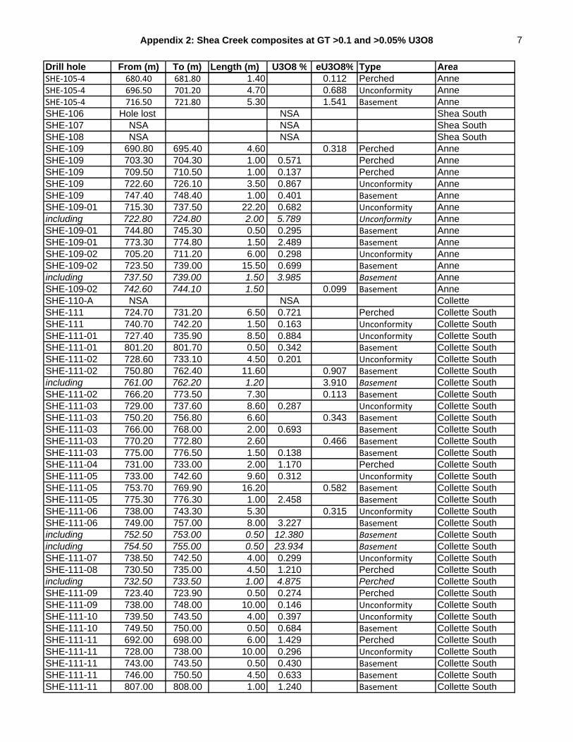
Appendix 2: Shea Creek composites at GT >0.1 and >0.05% U3O8 7
Drill hole From (m) To (m) Length (m) U3O8 % eU3O8% Type AreaSHE‐105‐4 680.40 681.80 1.40 0.112 Perched AnneSHE‐105‐4 696.50 701.20 4.70 0.688 Unconformity AnneSHE‐105‐4 716.50 721.80 5.30 1.541 Basement AnneSHE-106 Hole lost NSA Shea SouthSHE-107 NSA NSA Shea SouthSHE-108 NSA NSA Shea SouthSHE-109 690.80 695.40 4.60 0.318 Perched AnneSHE-109 703.30 704.30 1.00 0.571 Perched AnneSHE-109 709.50 710.50 1.00 0.137 Perched AnneSHE-109 722.60 726.10 3.50 0.867 Unconformity AnneSHE-109 747.40 748.40 1.00 0.401 Basement AnneSHE-109-01 715.30 737.50 22.20 0.682 Unconformity Anneincluding 722.80 724.80 2.00 5.789 Unconformity AnneSHE-109-01 744.80 745.30 0.50 0.295 Basement AnneSHE-109-01 773.30 774.80 1.50 2.489 Basement AnneSHE-109-02 705.20 711.20 6.00 0.298 Unconformity AnneSHE-109-02 723.50 739.00 15.50 0.699 Basement Anneincluding 737.50 739.00 1.50 3.985 Basement AnneSHE-109-02 742.60 744.10 1.50 0.099 Basement AnneSHE-110-A NSA NSA ColletteSHE-111 724.70 731.20 6.50 0.721 Perched Collette SouthSHE-111 740.70 742.20 1.50 0.163 Unconformity Collette SouthSHE-111-01 727.40 735.90 8.50 0.884 Unconformity Collette SouthSHE-111-01 801.20 801.70 0.50 0.342 Basement Collette SouthSHE-111-02 728.60 733.10 4.50 0.201 Unconformity Collette SouthSHE-111-02 750.80 762.40 11.60 0.907 Basement Collette Southincluding 761.00 762.20 1.20 3.910 Basement Collette SouthSHE-111-02 766.20 773.50 7.30 0.113 Basement Collette SouthSHE-111-03 729.00 737.60 8.60 0.287 Unconformity Collette SouthSHE-111-03 750.20 756.80 6.60 0.343 Basement Collette SouthSHE-111-03 766.00 768.00 2.00 0.693 Basement Collette SouthSHE-111-03 770.20 772.80 2.60 0.466 Basement Collette SouthSHE-111-03 775.00 776.50 1.50 0.138 Basement Collette SouthSHE-111-04 731.00 733.00 2.00 1.170 Perched Collette SouthSHE-111-05 733.00 742.60 9.60 0.312 Unconformity Collette SouthSHE-111-05 753.70 769.90 16.20 0.582 Basement Collette SouthSHE-111-05 775.30 776.30 1.00 2.458 Basement Collette SouthSHE-111-06 738.00 743.30 5.30 0.315 Unconformity Collette SouthSHE-111-06 749.00 757.00 8.00 3.227 Basement Collette Southincluding 752.50 753.00 0.50 12.380 Basement Collette Southincluding 754.50 755.00 0.50 23.934 Basement Collette SouthSHE-111-07 738.50 742.50 4.00 0.299 Unconformity Collette SouthSHE-111-08 730.50 735.00 4.50 1.210 Perched Collette Southincluding 732.50 733.50 1.00 4.875 Perched Collette SouthSHE-111-09 723.40 723.90 0.50 0.274 Perched Collette SouthSHE-111-09 738.00 748.00 10.00 0.146 Unconformity Collette SouthSHE-111-10 739.50 743.50 4.00 0.397 Unconformity Collette SouthSHE-111-10 749.50 750.00 0.50 0.684 Basement Collette SouthSHE-111-11 692.00 698.00 6.00 1.429 Perched Collette SouthSHE-111-11 728.00 738.00 10.00 0.296 Unconformity Collette SouthSHE-111-11 743.00 743.50 0.50 0.430 Basement Collette SouthSHE-111-11 746.00 750.50 4.50 0.633 Basement Collette SouthSHE-111-11 807.00 808.00 1.00 1.240 Basement Collette South

Appendix 2: Shea Creek composites at GT >0.1 and >0.05% U3O8 8
Drill hole From (m) To (m) Length (m) U3O8 % eU3O8% Type AreaSHE-111-12 727.00 732.50 5.50 0.351 Unconformity Collette SouthSHE-111-12 757.90 758.40 0.50 0.586 Basement Collette SouthSHE-111-12 762.00 773.50 11.50 0.879 Basement Collette Southincluding 772.00 773.00 1.00 4.810 Basement Collette SouthSHE-111-13 740.50 742.50 2.00 0.433 Perched Collette SouthSHE-111-13 753.50 763.00 9.50 0.310 Unconformity Collette SouthSHE-112 725.50 726.50 1.00 0.238 Basement AnneSHE-112 756.70 757.20 0.50 1.662 Basement AnneSHE-112-01 724.30 730.85 6.55 0.057 Unconformity AnneSHE-112-01 758.00 758.50 0.50 0.979 Basement AnneSHE-112-01 767.30 767.80 0.50 1.203 Basement AnneSHE-112-01 777.80 778.30 0.50 0.226 Basement AnneSHE-112-02 730.20 734.10 3.90 0.114 Unconformity AnneSHE-112-02 749.90 751.90 2.00 0.139 Basement AnneSHE-112-02 760.90 762.90 2.00 0.405 Basement AnneSHE-112-02 771.20 774.70 3.50 0.125 Basement AnneSHE-113 NSA NSA ColletteSHE-113-01 NSA NSA ColletteSHE-114 684.50 686.50 2.00 2.871 Perched Kiannaincluding 684.50 685.50 1.00 5.223 Perched KiannaSHE-114 713.40 715.40 2.00 0.816 Unconformity KiannaSHE-114 719.40 720.40 1.00 0.132 Basement KiannaSHE-114-01 683.50 692.50 9.00 0.556 Perched KiannaSHE-114-01 716.1 720.90 4.80 0.160 Unconformity KiannaSHE-114-01 731.20 731.70 0.50 0.203 Basement KiannaSHE-114-01 779.00 779.50 0.50 0.507 Basement KiannaSHE-114-01 807.00 810.50 3.50 1.576 Basement Kiannaincluding 810.00 810.50 0.50 8.725 Basement KiannaSHE-114-01 818.00 818.50 0.50 0.454 Basement KiannaSHE-114-02 724.50 726.00 1.50 0.152 Perched KiannaSHE-114-02 731.50 735.70 4.20 0.942 Unconformity Kiannaincluding 734.50 735.70 1.20 2.547 Unconformity KiannaSHE-114-03 741.60 742.10 0.50 0.224 Perched KiannaSHE-114-03 748.00 757.20 9.20 0.458 Basement KiannaSHE-114-04 725.50 733.00 7.50 1.025 Unconformity Kiannaincluding 726.00 728.50 2.50 2.596 Unconformity KiannaSHE-114-04 797.30 813.20 15.90 0.465 Basement KiannaSHE-114-05 608.50 623.00 14.50 0.068 Perched KiannaSHE-114-05 656.10 657.70 1.60 0.081 Perched KiannaSHE-114-05 669.40 669.90 0.50 0.258 Perched KiannaSHE-114-05 678.70 688.90 10.20 20.721 Perched Kiannaincluding 680.10 687.70 7.60 27.729 Perched KiannaSHE-114-05 713.70 718.20 4.50 0.316 Unconformity KiannaSHE-114-05 761.20 763.10 1.90 0.085 Basement KiannaSHE-114-05 809.60 825.30 15.70 0.816 Basement KiannaSHE-114-06 710.20 715.80 5.60 0.551 Unconformity KiannaSHE-114-07 662.40 663.60 1.20 0.226 Perched KiannaSHE-114-07 673.60 683.10 9.50 7.367 Perched Kiannaincluding 673.60 680.10 6.50 10.700 Perched Kiannaincluding 676.10 678.10 2.00 21.163 Perched KiannaSHE-114-07 716.00 723.00 7.00 0.110 Unconformity KiannaSHE-114-07 767.00 768.00 1.00 0.098 Basement KiannaSHE-114-07 780.90 781.80 0.90 0.131 Basement Kianna

Appendix 2: Shea Creek composites at GT >0.1 and >0.05% U3O8 9
Drill hole From (m) To (m) Length (m) U3O8 % eU3O8% Type AreaSHE-114-08 809.00 809.50 0.50 0.554 Basement KiannaSHE-114-08 838.70 850.50 11.80 3.578 Basement Kiannaincluding 838.70 840.20 1.50 21.143 Basement KiannaSHE-114-08 855.90 862.40 6.50 5.776 Basement Kiannaincluding 859.40 860.90 1.50 16.793 Basement KiannaSHE-114-09 677.00 699.20 22.20 4.637 Perched Kiannaincluding 684.10 687.30 3.20 8.001 Perched Kiannaincluding 689.90 698.70 8.80 7.851 Perched KiannaSHE-114-09 710.50 722.60 12.10 1.018 Unconformity KiannaSHE-114-09 730.00 731.00 1.00 0.759 Basement KiannaSHE-114-09 778.20 779.00 0.80 0.238 Basement KiannaSHE-114-09 805.80 815.00 9.20 0.674 Basement KiannaSHE-114-09 820.50 822.00 1.50 0.125 Basement KiannaSHE-114-09 826.00 834.50 8.50 1.100 Basement KiannaSHE-114-09 825.50 837.20 11.70 0.575 Basement Kiannaincluding 833.50 834.00 0.50 16.270 Basement KiannaSHE-114-09 861.00 867.50 6.50 0.326 Basement KiannaSHE-114-09 841.20 870.40 29.20 0.225 Basement KiannaSHE-114-10 Hole lost NSA KiannaSHE-114-10A 671.84 679.54 7.70 0.243 Perched KiannaSHE-114-10A 721.00 732.40 11.40 0.552 Unconformity Kiannaincluding 728.00 728.90 0.90 4.127 Unconformity KiannaSHE-114-10A 764.00 764.50 0.50 0.209 Basement KiannaSHE-114-10A 782.50 783.00 0.50 1.179 Basement KiannaSHE-114-11 679.30 694.60 15.30 4.580 Perched Kiannaincluding 686.10 692.50 6.40 9.967 Perched KiannaSHE-114-11 712.50 714.70 2.20 0.879 Unconformity KiannaSHE-114-11 792.00 792.50 0.50 7.746 Basement KiannaSHE-114-11 801.40 810.40 9.00 0.410 Basement KiannaSHE-114-11 818.50 863.50 45.00 4.093 Basement Kiannaincluding 818.50 819.00 0.50 11.083 Basement Kiannaincluding 829.50 833.00 3.50 10.300 Basement Kiannaincluding 837.00 843.00 6.00 18.073 Basement Kiannaincluding 846.00 847.00 1.00 15.109 Basement KiannaSHE-114-12 683.00 684.30 1.30 1.125 Perched KiannaSHE-114-12 682.10 688.60 6.50 1.370 Perched KiannaSHE-114-12 712.90 718.70 5.80 1.191 Unconformity KiannaSHE-114-12 795.50 796.00 0.50 0.315 Basement KiannaSHE-114-12 803.00 803.50 0.50 1.886 Basement KiannaSHE-114-12 809.00 813.00 4.00 0.213 Basement KiannaSHE-114-12 830.20 842.30 12.10 0.733 Basement KiannaSHE-114-12 839.50 842.50 3.00 0.278 Basement KiannaSHE-114-12 846.10 849.30 3.20 0.180 Basement KiannaSHE-114-12 902.20 904.60 2.40 0.078 Basement KiannaSHE-114-13 684.90 691.90 7.00 0.155 Perched KiannaSHE-114-13 713.60 715.80 2.20 0.081 Unconformity KiannaSHE-114-13 723.50 726.30 2.80 0.057 Basement KiannaSHE-114-13 809.50 811.00 1.50 7.719 Basement KiannaSHE-114-13 817.00 823.00 6.00 0.951 Basement Kiannaincluding 817.00 818.50 1.50 3.003 Basement KiannaSHE-114-14 626.00 626.80 0.80 0.144 Perched KiannaSHE-114-14 654.60 655.60 1.00 0.274 Perched KiannaSHE-114-14 713.00 721.00 8.00 0.276 Unconformity Kianna

Appendix 2: Shea Creek composites at GT >0.1 and >0.05% U3O8 10
Drill hole From (m) To (m) Length (m) U3O8 % eU3O8% Type AreaSHE-114-14 836.50 837.00 0.50 2.570 Basement KiannaSHE-114-14 845.60 847.00 1.40 0.475 Basement KiannaSHE-114-14 871.90 873.30 1.40 0.087 Basement KiannaSHE-114-14 886.30 888.00 1.70 0.144 Basement KiannaSHE-114-14 892.30 893.80 1.50 0.086 Basement KiannaSHE-114-14 910.50 911.80 1.30 0.101 Basement KiannaSHE-114-14 926.00 935.00 9.00 0.424 Basement KiannaSHE-114-15 713.90 716.40 2.50 0.174 Unconformity KiannaSHE-114-15 902.50 919.00 16.50 0.228 Basement KiannaSHE-114-16 NSA NSA KiannaSHE-114-17 717.50 728.00 10.50 0.380 Unconformity KiannaSHE-114-17 768.00 769.00 1.00 0.224 Basement KiannaSHE-114-17 883.00 890.80 7.80 4.382 Basement Kiannaincluding 883.00 884.50 1.50 20.023 Basement KiannaSHE-114-17 933.00 936.60 3.60 0.315 Basement KiannaSHE-115 716.00 721.00 5.00 0.411 Unconformity KiannaSHE-115-01 661.60 666.70 5.10 0.305 Perched KiannaSHE-115-01 728.00 739.80 11.80 0.293 Unconformity KiannaSHE-115-01 813.50 815.00 1.50 0.283 Basement KiannaSHE-115-01 911.50 915.00 3.50 6.268 Basement Kiannaincluding 912.00 912.50 0.50 40.086 Basement KiannaSHE-115-01 929.97 937.87 7.90 0.065 Basement KiannaSHE-115-02 734.10 751.50 17.40 0.514 Unconformity KiannaSHE-115-02 762.00 763.00 1.00 0.131 Basement KiannaSHE-115-02 772.50 774.50 2.00 0.462 Basement KiannaSHE-115-02 793.50 794.00 0.50 0.613 Basement KiannaSHE-115-02 829.00 830.00 1.00 0.210 Basement KiannaSHE-115-02 851.50 856.00 4.50 1.892 Basement Kiannaincluding 851.50 852.00 0.50 14.800 Basement KiannaSHE-115-03 735.60 747.80 12.20 9.335 Unconformity Kiannaincluding 739.60 740.50 0.90 20.285 Unconformity Kiannaincluding 742.00 746.30 4.30 21.154 Unconformity KiannaSHE-115-03 763.50 771.00 7.50 0.345 Basement KiannaSHE-115-03 838.00 838.50 0.50 0.401 Basement KiannaSHE-115-03 847.00 853.00 6.00 0.421 Basement KiannaSHE-115-03 856.50 857.50 1.00 0.247 Basement KiannaSHE-115-03 866.70 876.80 10.10 0.115 Basement KiannaSHE-115-03 892.50 897.50 5.00 0.514 Basement KiannaSHE-115-03 940.00 942.10 2.10 0.085 Basement KiannaSHE-115-03 980.50 982.00 1.50 0.179 Basement KiannaSHE-115-04 749.00 768.00 19.00 2.547 Unconformity Kiannaincluding 752.00 759.00 7.00 5.847 Unconformity Kiannaincluding 752.50 754.50 2.00 11.080 Unconformity KiannaSHE-115-04 841.00 842.00 1.00 0.163 Basement KiannaSHE-115-04 847.50 849.00 1.50 0.174 Basement KiannaSHE-115-04 895.50 896.00 0.50 0.365 Basement KiannaSHE-115-04 920.00 926.00 6.00 0.146 Basement KiannaSHE-115-05 730.50 737.70 7.20 7.827 Unconformity Kiannaincluding 732.50 735.20 2.70 20.360 Unconformity KiannaSHE-115-05 766.00 768.00 2.00 0.610 Basement KiannaSHE-115-05 792.00 796.50 4.50 3.643 Basement Kiannaincluding 794.50 795.00 0.50 30.418 Basement KiannaSHE-115-05 913.50 915.50 2.00 0.287 Basement Kianna
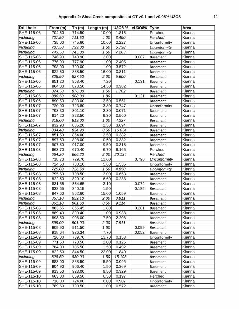
Appendix 2: Shea Creek composites at GT >0.1 and >0.05% U3O8 11
Drill hole From (m) To (m) Length (m) U3O8 % eU3O8% Type AreaSHE-115-06 704.50 714.50 10.00 1.815 Perched Kiannaincluding 707.50 711.50 4.00 3.490 Perched KiannaSHE-115-06 735.00 745.60 10.60 2.227 Unconformity Kiannaincluding 737.50 739.00 1.50 5.738 Unconformity Kiannaincluding 743.50 745.00 1.50 7.263 Unconformity KiannaSHE-115-06 746.90 748.90 2.00 0.087 Basement KiannaSHE-115-06 776.90 777.90 1.00 2.405 Basement KiannaSHE-115-06 798.00 799.00 1.00 3.572 Basement KiannaSHE-115-06 822.50 838.50 16.00 0.811 Basement Kiannaincluding 825.50 827.50 2.00 5.600 Basement KiannaSHE-115-06 851.20 858.40 7.20 0.131 Basement KiannaSHE-115-06 864.00 878.50 14.50 0.382 Basement Kiannaincluding 874.50 876.00 1.50 1.702 Basement KiannaSHE-115-06 886.50 888.30 1.80 0.121 Basement KiannaSHE-115-06 890.50 893.00 2.50 0.551 Basement KiannaSHE-115-07 720.00 723.80 3.80 0.747 Unconformity KiannaSHE-115-07 798.30 801.10 2.80 0.071 Basement KiannaSHE-115-07 814.20 823.50 9.30 0.560 Basement Kiannaincluding 818.00 819.00 1.00 4.227 Basement KiannaSHE-115-07 832.90 835.20 2.30 3.694 Basement Kiannaincluding 834.40 834.90 0.50 16.034 Basement KiannaSHE-115-07 851.50 854.00 2.50 0.382 Basement KiannaSHE-115-07 897.50 898.00 0.50 0.382 Basement KiannaSHE-115-07 907.50 917.00 9.50 0.315 Basement KiannaSHE-115-08 663.70 670.40 6.70 6.165 Perched Kiannaincluding 664.20 666.20 2.00 20.134 Perched KiannaSHE-115-08 718.70 729.70 11.00 0.790 Unconformity KiannaSHE-115-08 724.50 730.10 5.60 1.535 Unconformity Kiannaincluding 725.00 726.50 1.50 4.850 Unconformity KiannaSHE-115-08 795.50 798.50 3.00 0.653 Basement KiannaSHE-115-08 822.50 829.10 6.60 0.233 Basement KiannaSHE-115-08 831.55 834.65 3.10 0.072 Basement KiannaSHE-115-08 838.65 840.15 1.50 0.185 Basement KiannaSHE-115-08 847.60 862.60 15.00 1.059 Basement Kiannaincluding 857.10 859.10 2.00 3.911 Basement Kiannaincluding 861.10 861.60 0.50 9.114 Basement KiannaSHE-115-08 863.65 865.45 1.80 0.281 Basement KiannaSHE-115-08 889.40 890.40 1.00 0.938 Basement KiannaSHE-115-08 898.50 906.00 7.50 2.206 Basement Kiannaincluding 899.00 901.00 2.00 7.911 Basement KiannaSHE-115-08 909.90 911.50 1.60 0.099 Basement KiannaSHE-115-08 918.64 926.34 7.70 0.052 Basement KiannaSHE-115-09 726.00 739.70 13.70 0.153 Unconformity KiannaSHE-115-09 771.50 773.50 2.00 0.126 Basement KiannaSHE-115-09 784.00 785.50 1.50 0.492 Basement KiannaSHE-115-09 822.50 844.50 22.00 1.840 Basement Kiannaincluding 828.50 830.00 1.50 15.193 Basement KiannaSHE-115-09 883.00 888.50 5.50 0.095 Basement KiannaSHE-115-09 904.90 906.40 1.50 0.369 Basement KiannaSHE-115-09 913.50 923.00 9.50 0.329 Basement KiannaSHE-115-10 663.00 669.50 6.50 0.197 Perched KiannaSHE-115-10 718.00 724.00 6.00 0.907 Unconformity KiannaSHE-115-10 789.50 790.50 1.00 0.572 Basement Kianna
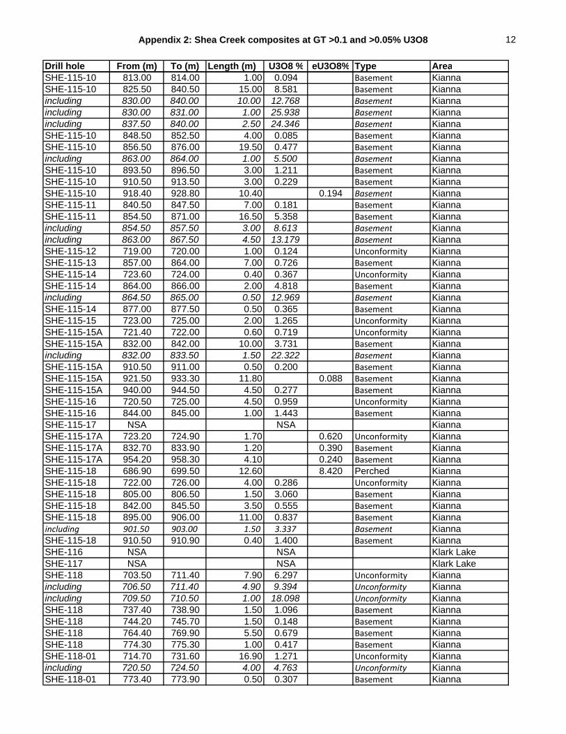
Appendix 2: Shea Creek composites at GT >0.1 and >0.05% U3O8 12
Drill hole From (m) To (m) Length (m) U3O8 % eU3O8% Type AreaSHE-115-10 813.00 814.00 1.00 0.094 Basement KiannaSHE-115-10 825.50 840.50 15.00 8.581 Basement Kiannaincluding 830.00 840.00 10.00 12.768 Basement Kiannaincluding 830.00 831.00 1.00 25.938 Basement Kiannaincluding 837.50 840.00 2.50 24.346 Basement KiannaSHE-115-10 848.50 852.50 4.00 0.085 Basement KiannaSHE-115-10 856.50 876.00 19.50 0.477 Basement Kiannaincluding 863.00 864.00 1.00 5.500 Basement KiannaSHE-115-10 893.50 896.50 3.00 1.211 Basement KiannaSHE-115-10 910.50 913.50 3.00 0.229 Basement KiannaSHE-115-10 918.40 928.80 10.40 0.194 Basement KiannaSHE-115-11 840.50 847.50 7.00 0.181 Basement KiannaSHE-115-11 854.50 871.00 16.50 5.358 Basement Kiannaincluding 854.50 857.50 3.00 8.613 Basement Kiannaincluding 863.00 867.50 4.50 13.179 Basement KiannaSHE-115-12 719.00 720.00 1.00 0.124 Unconformity KiannaSHE-115-13 857.00 864.00 7.00 0.726 Basement KiannaSHE-115-14 723.60 724.00 0.40 0.367 Unconformity KiannaSHE-115-14 864.00 866.00 2.00 4.818 Basement Kiannaincluding 864.50 865.00 0.50 12.969 Basement KiannaSHE-115-14 877.00 877.50 0.50 0.365 Basement KiannaSHE-115-15 723.00 725.00 2.00 1.265 Unconformity KiannaSHE-115-15A 721.40 722.00 0.60 0.719 Unconformity KiannaSHE-115-15A 832.00 842.00 10.00 3.731 Basement Kiannaincluding 832.00 833.50 1.50 22.322 Basement KiannaSHE-115-15A 910.50 911.00 0.50 0.200 Basement KiannaSHE-115-15A 921.50 933.30 11.80 0.088 Basement KiannaSHE-115-15A 940.00 944.50 4.50 0.277 Basement KiannaSHE-115-16 720.50 725.00 4.50 0.959 Unconformity KiannaSHE-115-16 844.00 845.00 1.00 1.443 Basement KiannaSHE-115-17 NSA NSA KiannaSHE-115-17A 723.20 724.90 1.70 0.620 Unconformity KiannaSHE-115-17A 832.70 833.90 1.20 0.390 Basement KiannaSHE-115-17A 954.20 958.30 4.10 0.240 Basement KiannaSHE-115-18 686.90 699.50 12.60 8.420 Perched KiannaSHE-115-18 722.00 726.00 4.00 0.286 Unconformity KiannaSHE-115-18 805.00 806.50 1.50 3.060 Basement KiannaSHE-115-18 842.00 845.50 3.50 0.555 Basement KiannaSHE-115-18 895.00 906.00 11.00 0.837 Basement Kiannaincluding 901.50 903.00 1.50 3.337 Basement KiannaSHE-115-18 910.50 910.90 0.40 1.400 Basement KiannaSHE-116 NSA NSA Klark LakeSHE-117 NSA NSA Klark LakeSHE-118 703.50 711.40 7.90 6.297 Unconformity Kiannaincluding 706.50 711.40 4.90 9.394 Unconformity Kiannaincluding 709.50 710.50 1.00 18.098 Unconformity KiannaSHE-118 737.40 738.90 1.50 1.096 Basement KiannaSHE-118 744.20 745.70 1.50 0.148 Basement KiannaSHE-118 764.40 769.90 5.50 0.679 Basement KiannaSHE-118 774.30 775.30 1.00 0.417 Basement KiannaSHE-118-01 714.70 731.60 16.90 1.271 Unconformity Kiannaincluding 720.50 724.50 4.00 4.763 Unconformity KiannaSHE-118-01 773.40 773.90 0.50 0.307 Basement Kianna

Appendix 2: Shea Creek composites at GT >0.1 and >0.05% U3O8 13
Drill hole From (m) To (m) Length (m) U3O8 % eU3O8% Type AreaSHE-118-01 853.40 879.90 26.50 0.354 Basement KiannaSHE-118-02 743.20 745.80 2.60 0.216 Unconformity KiannaSHE-118-03 734.00 740.50 6.50 1.020 Unconformity Kiannaincluding 735.50 737.70 2.20 2.377 Unconformity KiannaSHE-118-04 715.55 732.85 17.30 0.981 Unconformity Kiannaincluding 725.75 731.95 6.20 1.841 Unconformity KiannaSHE-118-04 796.00 802.50 6.50 0.471 Basement KiannaSHE-118-04 813.00 820.50 7.50 0.113 Basement KiannaSHE-118-04 846.00 847.50 1.50 0.434 Basement KiannaSHE-118-04 859.00 860.50 1.50 0.726 Basement KiannaSHE-118-04 874.50 878.50 4.00 0.072 Basement KiannaSHE-118-05 704.30 717.50 13.20 1.577 Unconformity Kiannaincluding 708.50 712.00 3.50 5.510 Unconformity Kiannaincluding 710.50 712.00 1.50 10.149 Unconformity KiannaSHE-118-05 722.50 724.50 2.00 0.151 Basement KiannaSHE-118-05 732.50 735.00 2.50 0.409 Basement KiannaSHE-118-05 746.50 748.50 2.00 0.109 Basement KiannaSHE-118-05A 706.00 721.00 15.00 1.475 Unconformity Kiannaincluding 708.00 711.50 3.50 5.791 Unconformity Kiannaincluding 710.50 711.50 1.00 12.556 Unconformity KiannaSHE-118-05A 725.30 744.10 18.80 0.103 Basement KiannaSHE-118-05A 747.50 749.00 1.50 0.202 Basement KiannaSHE-118-06 Hole lost NSA KiannaSHE-118-06A 701.00 707.00 6.00 2.609 Unconformity Kiannaincluding 704.50 706.30 1.80 8.180 Unconformity KiannaSHE-118-06B 702.50 708.50 6.00 4.028 Unconformity Kiannaincluding 706.00 708.00 2.00 11.831 Unconformity KiannaSHE-118-06B 759.00 759.50 0.50 0.295 Basement KiannaSHE-118-06B 804.50 805.00 0.50 0.225 Basement KiannaSHE-118-06B 807.00 809.50 2.50 1.136 Basement KiannaSHE-118-07 704.50 710.50 6.00 0.909 Unconformity Kiannaincluding 709.00 709.80 0.80 4.292 Unconformity KiannaSHE-118-07 803.00 803.50 0.50 1.099 Basement KiannaSHE-118-08 705.50 715.50 10.00 2.030 Unconformity Kiannaincluding 711.50 713.80 2.30 8.468 Unconformity KiannaSHE-118-08 772.50 773.00 0.50 0.317 Basement KiannaSHE-118-08 778.00 778.50 0.50 0.271 Basement KiannaSHE-118-08 797.50 807.00 9.50 2.188 Basement Kiannaincluding 801.50 804.00 2.50 7.951 Basement KiannaSHE-118-08 817.00 820.00 3.00 2.343 Basement Kiannaincluding 818.00 819.00 1.00 6.278 Basement KiannaSHE-118-09 706.00 717.50 11.50 2.275 Unconformity Kiannaincluding 711.50 715.80 4.30 5.011 Unconformity Kiannaincluding 711.50 713.00 1.50 8.037 Unconformity KiannaSHE-118-09 724.70 734.90 10.20 0.065 Basement KiannaSHE-118-09 749.60 752.20 3.50 0.071 Basement KiannaSHE-118-09 764.00 769.00 5.00 1.802 Basement Kiannaincluding 765.00 765.50 0.50 7.392 Basement KiannaSHE-118-10 718.50 722.40 3.90 0.233 Unconformity KiannaSHE-118-10 719.00 721.60 2.60 0.416 Unconformity KiannaSHE-118-10 797.50 803.60 6.10 0.172 Basement KiannaSHE-118-11 737.30 740.50 3.20 5.863 Unconformity Kiannaincluding 738.90 739.50 0.60 24.300 Unconformity Kianna
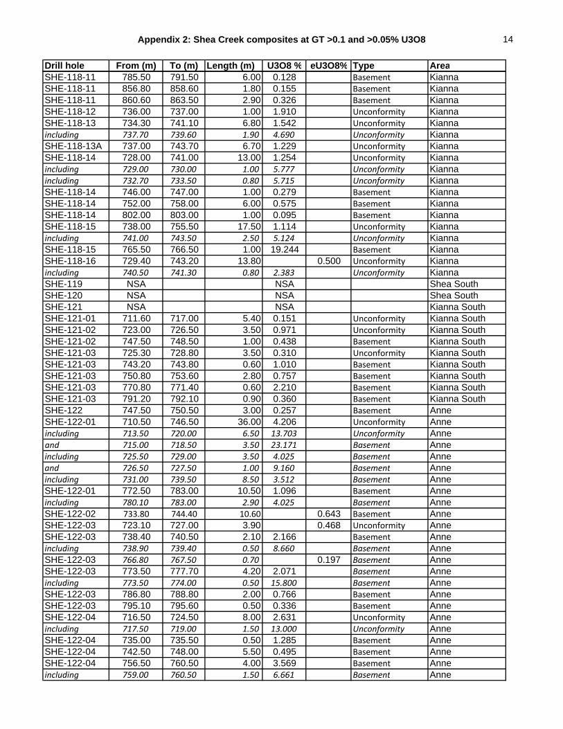
Appendix 2: Shea Creek composites at GT >0.1 and >0.05% U3O8 14
Drill hole From (m) To (m) Length (m) U3O8 % eU3O8% Type AreaSHE-118-11 785.50 791.50 6.00 0.128 Basement KiannaSHE-118-11 856.80 858.60 1.80 0.155 Basement KiannaSHE-118-11 860.60 863.50 2.90 0.326 Basement KiannaSHE-118-12 736.00 737.00 1.00 1.910 Unconformity KiannaSHE-118-13 734.30 741.10 6.80 1.542 Unconformity Kiannaincluding 737.70 739.60 1.90 4.690 Unconformity KiannaSHE-118-13A 737.00 743.70 6.70 1.229 Unconformity KiannaSHE-118-14 728.00 741.00 13.00 1.254 Unconformity Kiannaincluding 729.00 730.00 1.00 5.777 Unconformity Kiannaincluding 732.70 733.50 0.80 5.715 Unconformity KiannaSHE-118-14 746.00 747.00 1.00 0.279 Basement KiannaSHE-118-14 752.00 758.00 6.00 0.575 Basement KiannaSHE-118-14 802.00 803.00 1.00 0.095 Basement KiannaSHE-118-15 738.00 755.50 17.50 1.114 Unconformity Kiannaincluding 741.00 743.50 2.50 5.124 Unconformity KiannaSHE-118-15 765.50 766.50 1.00 19.244 Basement KiannaSHE-118-16 729.40 743.20 13.80 0.500 Unconformity Kiannaincluding 740.50 741.30 0.80 2.383 Unconformity KiannaSHE-119 NSA NSA Shea SouthSHE-120 NSA NSA Shea SouthSHE-121 NSA NSA Kianna SouthSHE-121-01 711.60 717.00 5.40 0.151 Unconformity Kianna SouthSHE-121-02 723.00 726.50 3.50 0.971 Unconformity Kianna SouthSHE-121-02 747.50 748.50 1.00 0.438 Basement Kianna SouthSHE-121-03 725.30 728.80 3.50 0.310 Unconformity Kianna SouthSHE-121-03 743.20 743.80 0.60 1.010 Basement Kianna SouthSHE-121-03 750.80 753.60 2.80 0.757 Basement Kianna SouthSHE-121-03 770.80 771.40 0.60 2.210 Basement Kianna SouthSHE-121-03 791.20 792.10 0.90 0.360 Basement Kianna SouthSHE-122 747.50 750.50 3.00 0.257 Basement AnneSHE-122-01 710.50 746.50 36.00 4.206 Unconformity Anneincluding 713.50 720.00 6.50 13.703 Unconformity Anneand 715.00 718.50 3.50 23.171 Basement Anneincluding 725.50 729.00 3.50 4.025 Basement Anneand 726.50 727.50 1.00 9.160 Basement Anneincluding 731.00 739.50 8.50 3.512 Basement AnneSHE-122-01 772.50 783.00 10.50 1.096 Basement Anneincluding 780.10 783.00 2.90 4.025 Basement AnneSHE-122-02 733.80 744.40 10.60 0.643 Basement AnneSHE-122-03 723.10 727.00 3.90 0.468 Unconformity AnneSHE-122-03 738.40 740.50 2.10 2.166 Basement Anneincluding 738.90 739.40 0.50 8.660 Basement AnneSHE-122-03 766.80 767.50 0.70 0.197 Basement AnneSHE-122-03 773.50 777.70 4.20 2.071 Basement Anneincluding 773.50 774.00 0.50 15.800 Basement AnneSHE-122-03 786.80 788.80 2.00 0.766 Basement AnneSHE-122-03 795.10 795.60 0.50 0.336 Basement AnneSHE-122-04 716.50 724.50 8.00 2.631 Unconformity Anneincluding 717.50 719.00 1.50 13.000 Unconformity AnneSHE-122-04 735.00 735.50 0.50 1.285 Basement AnneSHE-122-04 742.50 748.00 5.50 0.495 Basement AnneSHE-122-04 756.50 760.50 4.00 3.569 Basement Anneincluding 759.00 760.50 1.50 6.661 Basement Anne

Appendix 2: Shea Creek composites at GT >0.1 and >0.05% U3O8 15
Drill hole From (m) To (m) Length (m) U3O8 % eU3O8% Type AreaSHE-122-04 780.50 781.50 1.00 0.117 Basement AnneSHE-122-05 727.00 747.50 20.50 3.642 Unconformity Anneincluding 727.50 733.50 6.00 11.407 Unconformity Anneand 728.50 732.50 4.00 15.635 Unconformity AnneSHE-122-06 713.00 737.00 24.00 0.334 Unconformity AnneSHE-122-06 752.50 755.00 2.50 1.008 Basement AnneSHE-122-06 760.00 764.00 4.00 0.188 Basement AnneSHE-122-06 790.00 793.50 3.50 0.898 Basement AnneSHE-122-07 719.10 721.50 2.40 0.353 Unconformity AnneSHE-122-07 771.00 772.00 1.00 1.905 Basement AnneSHE-122-07 787.00 787.50 0.50 0.228 Basement AnneSHE-123 NSA NSA Kianna SouthSHE-123-01 740.00 741.50 1.50 0.451 Unconformity Kianna SouthSHE-123-01 781.30 789.70 8.40 0.095 Basement Kianna SouthSHE-123-02 786.50 787.00 0.50 0.836 Basement Kianna SouthSHE-123-02 800.50 804.00 3.50 4.841 Basement Kianna Southincluding 800.50 802.50 2.00 7.850 Basement Kianna SouthSHE-123-02 816.50 817.00 0.50 0.489 Basement Kianna SouthSHE-123-02 824.50 828.50 4.00 0.344 Basement Kianna SouthSHE-123-03 714.10 718.60 4.50 0.550 Perched Kianna SouthSHE-123-03 744.40 751.50 7.10 0.886 Unconformity Kianna Southincluding 745.90 746.40 0.50 6.131 Unconformity Kianna SouthSHE-123-03 768.60 776.10 7.50 0.205 Basement Kianna SouthSHE-123-03 782.10 784.20 2.10 1.917 Basement Kianna SouthSHE-123-03 799.50 799.90 0.40 0.246 Basement Kianna SouthSHE-123-04 741.00 756.50 15.50 0.235 Unconformity Kianna SouthSHE-123-04 765.00 770.50 5.50 0.324 Basement Kianna SouthSHE-123-04 787.10 787.60 0.50 2.004 Basement Kianna SouthSHE-123-05 NSA NSA Kianna SouthSHE-123-06 733.00 736.60 3.60 11.114 Unconformity Kianna Southincluding 734.50 735.60 1.10 32.262 Unconformity Kianna SouthSHE-123-06 844.00 845.50 1.50 0.126 Basement Kianna SouthSHE-123-07 729.50 732.80 3.30 5.198 Unconformity Kianna Southincluding 731.00 732.30 1.30 11.491 Unconformity Kianna SouthSHE-123-07 740.30 741.30 1.00 0.128 Basement Kianna SouthSHE-123-07 761.50 762.50 1.00 0.159 Basement Kianna SouthSHE-123-07 792.30 802.00 9.70 0.159 Basement Kianna SouthSHE-123-08 732.50 737.40 4.90 8.411 Unconformity Kianna Southincluding 732.50 734.50 2.00 19.757 Unconformity Kianna SouthSHE-123-08 822.10 823.10 1.00 0.111 Basement Kianna SouthSHE-123-09 733.00 735.80 2.80 2.506 Unconformity Kianna Southincluding 734.00 735.00 1.00 5.730 Unconformity Kianna SouthSHE-123-09 809.50 817.00 7.50 1.668 Basement Kianna Southincluding 810.00 810.50 0.50 18.392 Basement Kianna SouthSHE-123-09 812.10 819.50 7.40 1.220 Basement Kianna SouthSHE-123-09 821.50 825.00 3.50 0.180 Basement Kianna SouthSHE-123-10 NSA NSA Kianna SouthSHE-123-11 726.70 727.50 0.80 0.586 Unconformity Kianna SouthSHE-123-11 736.00 739.00 3.00 0.045 Basement Kianna SouthSHE-123-12 734.00 739.00 5.00 0.110 Unconformity Kianna SouthSHE-123-12 809.50 811.50 2.00 4.231 Basement Kianna SouthSHE-123-13 730.00 733.00 3.00 0.095 Unconformity Kianna SouthSHE-124 768.60 776.80 8.20 0.086 Basement Anne

Appendix 2: Shea Creek composites at GT >0.1 and >0.05% U3O8 16
Drill hole From (m) To (m) Length (m) U3O8 % eU3O8% Type AreaSHE-125 NSA NSA AnneSHE-125-01 716.00 718.00 2.00 0.316 Basement AnneSHE-125-01 733.80 734.30 0.50 0.585 Basement AnneSHE-125-01 781.30 784.30 3.00 0.137 Basement AnneSHE-125-02 742.80 744.30 1.50 0.121 Basement AnneSHE-125-03 709.00 727.40 18.40 0.347 Unconformity AnneSHE-125-03 755.60 762.00 6.40 0.158 Basement AnneSHE-126 723.00 724.50 1.50 0.153 Unconformity Collette SouthSHE-126 749.90 763.70 13.80 0.402 Basement Collette SouthSHE-126 768.20 768.70 0.50 0.407 Basement Collette SouthSHE-126 774.60 776.70 2.10 0.176 Basement Collette SouthSHE-126-01 NSA NSA Collette SouthSHE-126-01A 756.00 766.20 10.20 0.700 Basement Collette Southincluding 757.50 758.50 1.00 4.521 Basement Collette SouthSHE-126-01A 773.40 773.90 0.50 0.317 Basement Collette SouthSHE-126-02 772.80 773.30 0.50 0.258 Basement Collette SouthSHE-126-02 821.00 822.00 1.00 0.220 Basement Collette SouthSHE-126-03 721.00 722.50 1.50 0.272 Basement Collette SouthSHE-126-03 762.90 766.90 4.00 0.164 Basement Collette SouthSHE-126-04 NSA NSA Collette SouthSHE-126-05 778.60 779.80 1.20 2.240 Basement Collette SouthSHE-127 736.90 737.40 0.50 0.240 Basement SE of AnneSHE-128 NSA NSA SE of AnneSHE-129 NSA NSA SE of AnneSHE-130 NSA NSA KiannaSHE-130-01 NSA NSA KiannaSHE-130-1A 843.50 844.50 1.00 0.171 Basement KiannaSHE-130-1A 868.50 869.50 1.00 0.174 Basement KiannaSHE-130-1A 914.50 915.50 1.00 0.283 Basement KiannaSHE-130-02 NSA NSA KiannaHYD-07-01 NSA NSA Kianna SouthHYD-07-02 NSA NSA KiannaHYD-07-03 NSA NSA AnneHYD-07-04 NSA NSA KiannaHYD-07-05 NSA NSA Kianna SouthP08-01 712.4 713.10 0.70 0.630 Unconformity KiannaP08-02 NSA NSA Kianna