udc 624 . 155 . 8 study on uplift resistance of screwed ... · udc 624 . 155 . 8 *1 building ... a...
TRANSCRIPT

NIPPON STEEL TECHNICAL REPORT No. 92 July 2005
- 73 -
UDC 624 . 155 . 8
*1 Building Construction Division *2 Steel Research Laboratories
Study on Uplift Resistance of Screwed Steel PileMakoto NAGATA*1 Hisashi HIRATA*2
Abstract
A screwed steel pipe pile exerts a huge resistance at the lower end against an
uplifting load owing to the anchoring effect of the spiral wing provided at the pile
end. Uplift tests of reduced-scale screwed pipe piles using purpose-made model test
equipment clarified the relationship between pile diameter, wing diameter, pile-end
depth and the uplift resistance at the pile end. Visible tests and earth pressure meas-
urement with reduced-scale piles carried out after the above disclosed the soil move-
ment and earth pressure near the pile end at pile driving and uplifting. Based on
these results, the shape of the shear fracture zone of soil that brought about the
uplift resistance was estimated.
1. IntroductionA screwed pile is a steel pipe pile with a spiral wing provided at
the lower end (toe) to drill into soil (see Fig. 1). Since the pile isdriven into soil under rotating torque, it is not necessary to removesoil for pile driving. Tensile loading tests of real-size screwed pileshave disclosed that this type of pile has a large pile-end uplift resist-ance owing to the anchoring effect of the wing spirally driven intosoil1,2). However, there have been only a limited number of studieson the uplift resistance of a screwed pile, and many aspects of theresistance remain unclear.
The present paper reports uplifting tests of reduced-scale screwedpiles using purpose-made test facilities for reduced-scale specimens3)
and the analysis of the characteristics of the pile-end uplift resist-ance based on the results of the tests. The paper also reports theinvestigation of the soil region in which shear fracture occurs byactual observation of sand movement, the measurement of earth pres-sure during driving and uplifting of piles, and studies on the magni-tude and distribution of earth pressure acting on the shear fracturezone of soil based on the results of the above tests and measurement.
2. Uplifting Test2.1 Outline of test equipment
The authors drove model piles to prescribed depths by rotationand then conducted loading tests (or uplifting tests) in the same man-ner as explained in reference3) using the following facilities and speci-mens: (A) a cylindrical sand-soil tank 1,200 mm in height and 1,200
mm in diameter filled with silica sand No. 6 having a relative den-sity of 84% and equipped with pressurizing facilities; (B) a pile-driving and loading device for applying torque and vertical upliftingload to specimen piles at the top; (C) reduced-scale double-tube modelpiles; and (D) a measurement device for real-time monitoring of thetorque and axial force.2.2 Test parameters
In order to study the relationship between uplift resistance andthe depth of a pile end, the pile-end depth was changed from 100 to800 mm. In addition, for studying the influence of the wing diam-eter ratio (Rd), specimen piles 40 mm in pile diameter (Dp) havingwing diameters 1.5 to 3.0 times the pile diameter were prepared.Further, for studying the influence of the wing diameter ratio, speci-
Fig. 1 Pile toe

NIPPON STEEL TECHNICAL REPORT No. 92 July 2005
- 74 -
men piles 100 mm in wing diameter (Dw) having pile diameters of40, 50 and 60 mm were also prepared. Table 1 shows the combina-tions of the test parameters. The confining pressures of the soil wereset as follows for all the specimens: the axial pressure at 300 kPa andthe lateral pressure at 150 kPa. The load imposed on the top of a pileduring pile driving (pile top axial force) was set at 1 kN also for allthe specimens.
3. Test Results3.1 General
Fig. 2 shows a typical example of the test results. What is shownis the result of Case 11, where the pile diameter was 40 mm, thewing diameter was 80 mm, and the pile end depth was 600 mm.Here, the axial force at the pile top is that applied to the pile top, theresistance at the pile end is the axial force measured just below theend of a double-tube specimen pile, and the friction on the pile sur-face is that measured at the top of the same. The displacement of a
pile was measured at the pile top.One sees here that the pile-end uplift resistance hit a maximum at
a displacement of roughly 14 mm (0.35 Dp), and then decreased to aresidual resistance of roughly 65% of the maximum as the pile waslifted further. The surface friction hit a maximum at a displacementof roughly 6 mm, and then decreased to a residual resistance ofroughly 75% of the maximum. These tendencies were substantiallythe same with all the specimens.3.2 Analysis of uplift resistance
Fig. 3 shows the relationship between pile-end depth and upliftresistance. With all the wing diameters, the pile-end uplift resist-ance tended to converge upon a certain value when the depth waslarger than a certain value. This seems to indicate that the fracturezone of the sand soil resulting from the anchoring effect of the pile-end wing does not expand more than a certain extent.
Next, Fig. 4 shows the relationship between wing diameter ratio(Rd) and pile-end uplift resistance. The uplift resistance tended tochange substantially in linear proportion with the wing diameter ra-tio at all the pile-end depths. From the results of Figs. 3 and 4, the
Table 1 Test parameter
Test caseNo.12345678910111213141516171819202122
Test name
4D15W3P10L3S10H4D15W3P10L3S30H4D15W3P10L3S60H4D15W3P10L3S80H4D175W3P10L3S10H4D175W3P10L3S30H4D175W3P10L3S60H4D175W3P10L3S80H4D20W3P10L3S10H4D20W3P10L3S30H4D20W3P10L3S60H4D20W3P10L3S80H4D25W3P10L3S10H4D25W3P10L3S30H4D25W3P10L3S60H4D25W3P10L3S80H4D30W3P10L3S10H4D30W3P10L3S30H4D30W3P10L3S60H4D30W3P10L3S80H5D20W3P10L3S60H6D167W3P10L3S60H
Dp(mm)
40404040404040404040404040404040404040405060
Rd
1.51.51.51.51.751.751.751.752.02.02.02.02.52.52.52.53.03.03.03.02.01.67
Dw(mm)
606060607070707080808080100100100100120120120120100100
Pile toe depth(mm)100300600800100300600800100300600800100300600800100300600800600600
Axial (kPa)300300300300300300300300300300300300300300300300300300300300300300
Lateral (kPa)150150150150150150150150150150150150150150150150150150150150150150
Pile top load(kN)
1111111111111111111111
Confining pressure
Fig. 2 Relationship between uplifting load and displacement Fig. 3 Relationships between depth and uplift resistance
NIPPON STEEL TECHNICAL REPORT No. 92 July 2005
- 75 -
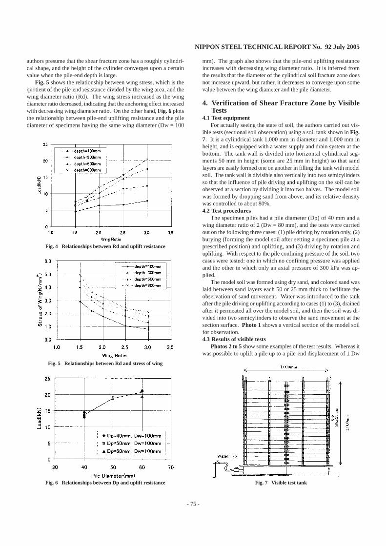
authors presume that the shear fracture zone has a roughly cylindri-cal shape, and the height of the cylinder converges upon a certainvalue when the pile-end depth is large.
Fig. 5 shows the relationship between wing stress, which is thequotient of the pile-end resistance divided by the wing area, and thewing diameter ratio (Rd). The wing stress increased as the wingdiameter ratio decreased, indicating that the anchoring effect increasedwith decreasing wing diameter ratio. On the other hand, Fig. 6 plotsthe relationship between pile-end uplifting resistance and the pilediameter of specimens having the same wing diameter (Dw = 100
mm). The graph also shows that the pile-end uplifting resistanceincreases with decreasing wing diameter ratio. It is inferred fromthe results that the diameter of the cylindrical soil fracture zone doesnot increase upward, but rather, it decreases to converge upon somevalue between the wing diameter and the pile diameter.
4. Verification of Shear Fracture Zone by VisibleTests
4.1 Test equipmentFor actually seeing the state of soil, the authors carried out vis-
ible tests (sectional soil observation) using a soil tank shown in Fig.7. It is a cylindrical tank 1,000 mm in diameter and 1,000 mm inheight, and is equipped with a water supply and drain system at thebottom. The tank wall is divided into horizontal cylindrical seg-ments 50 mm in height (some are 25 mm in height) so that sandlayers are easily formed one on another in filling the tank with modelsoil. The tank wall is divisible also vertically into two semicylindersso that the influence of pile driving and uplifting on the soil can beobserved at a section by dividing it into two halves. The model soilwas formed by dropping sand from above, and its relative densitywas controlled to about 80%.4.2 Test procedures
The specimen piles had a pile diameter (Dp) of 40 mm and awing diameter ratio of 2 (Dw = 80 mm), and the tests were carriedout on the following three cases: (1) pile driving by rotation only, (2)burying (forming the model soil after setting a specimen pile at aprescribed position) and uplifting, and (3) driving by rotation anduplifting. With respect to the pile confining pressure of the soil, twocases were tested: one in which no confining pressure was appliedand the other in which only an axial pressure of 300 kPa was ap-plied.
The model soil was formed using dry sand, and colored sand waslaid between sand layers each 50 or 25 mm thick to facilitate theobservation of sand movement. Water was introduced to the tankafter the pile driving or uplifting according to cases (1) to (3), drainedafter it permeated all over the model soil, and then the soil was di-vided into two semicylinders to observe the sand movement at thesection surface. Photo 1 shows a vertical section of the model soilfor observation.4.3 Results of visible tests
Photos 2 to 5 show some examples of the test results. Whereas itwas possible to uplift a pile up to a pile-end displacement of 1 Dw
Fig. 6 Relationships between Dp and uplift resistance
Fig. 5 Relationships between Rd and stress of wing
Fig. 4 Relationships between Rd and uplift resistance
Fig. 7 Visible test tank

NIPPON STEEL TECHNICAL REPORT No. 92 July 2005
- 76 -
looked to be roughly cylindrical (as contoured with white lines), asexpected.
Fig. 8 compares a buried pile and a spirally driven pile in termsof uplift resistance. The uplift resistance of a driven pile was roughly5 times that of a buried one, which seems to indicate that the soilaround the pile was compacted by the driving force of the spiralwing. Photo 4 shows that the sand has moved upward by a distanceroughly corresponding to the pile displacement per rotation during
Photo 2 Screw-piling + uplifting test (no confining pressure)
Photo 3 Burying + uplifting test (no confining pressure)
Photo 4 Screw-piling + uplifting test (under confining pressure)
Photo 5 Burying + uplifting test (under confining pressure)
when no confining pressure was applied (Photos 2 and 3), when theaxial pressure of 300 kPa was applied (Photos 4 and 5), the resist-ance at the pile end was so large that the maximum uplifting capac-ity of the test equipment could produce a pile-end displacement ofonly 0.1 Dw or so, and it was impossible to confirm a maximumpile-end uplift resistance. Photographs showed the color change ofsand in the portion just above the upper surface of the wing (seePhoto 3); this resulted presumably from the formation of a compressedregion serving as an active wedge when uplifting force was applied.The inversed parabolic shape of the compressed region indicates that,the nearer to the root of the wing, the greater the compression forcebecomes. No parabolic soil movement was observed in the fracturezone of the soil above the wing, and the shape of the fracture zone
Photo 1 Visible condition
Fig. 8 Uplift resistance
NIPPON STEEL TECHNICAL REPORT No. 92 July 2005
- 77 -
the passage of the wing. This indicates that the wing exerts pile-driving force by pressing on the soil above the upper surface, leav-ing only a small soil disturbance after the pile-driving work.
5. Earth Pressure Measurement5.1 Measurement method and cases examined
For the purpose of quantifying the influence of the soil liftingresulting from the pile-driving force of the wing on the soil above itobserved in the visible tests and confirming the distribution andmagnitude of the earth pressure on the shear fracture zone underuplifting loads, the earth pressure during pile driving and upliftingwas measured by the authors.
The measurement was done using the same model-soil tank forthe uplifting tests equipped with pressurizing facilities and installingearth pressure gauges 30 mm in diameter at positions about 20 mmfrom the wing edge to measure horizontal earth pressure (see theright-hand side of Fig. 9). The confining pressures of the soil wereset as follows: the axial pressure at 300 kPa and the lateral pressureat 150 kPa.
The measurement was done on the following cases: (1) the pilediameter (Dp) was kept constant at 40 mm and the wing diameterratio (Rd) was changed to 1.5, 1.75, 2.0, 2.5 and 3.0; and (2) thewing diameter (Dw) was kept constant at 100 mm and the pile diam-eter (Dp) was changed to 40, 50 and 60 mm.5.2 Measurement results
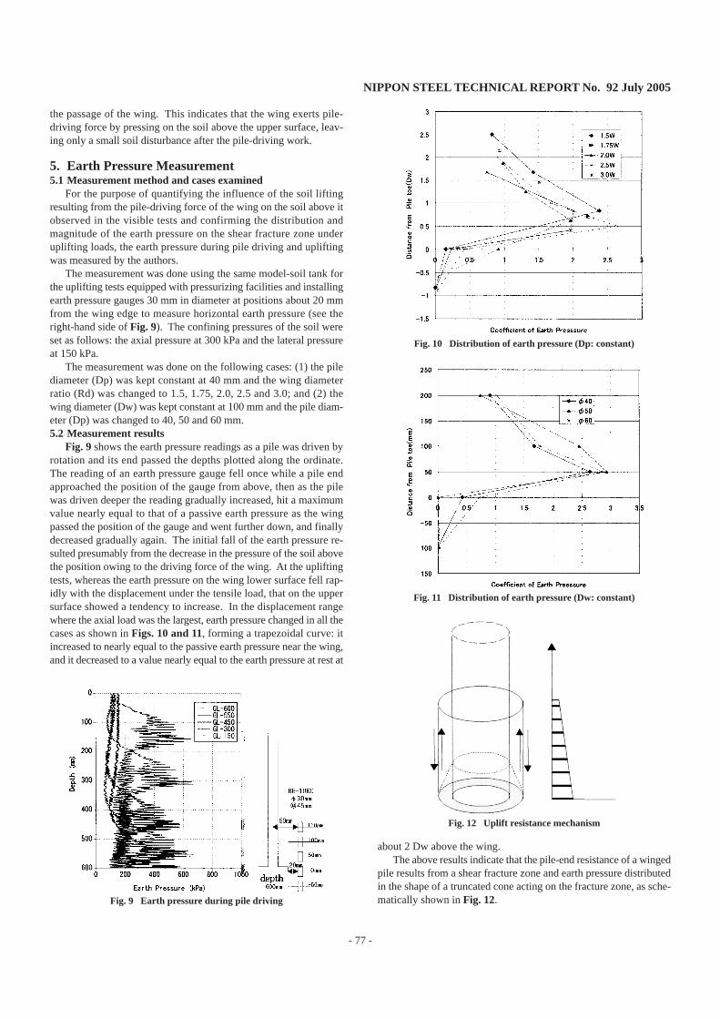
Fig. 9 shows the earth pressure readings as a pile was driven byrotation and its end passed the depths plotted along the ordinate.The reading of an earth pressure gauge fell once while a pile endapproached the position of the gauge from above, then as the pilewas driven deeper the reading gradually increased, hit a maximumvalue nearly equal to that of a passive earth pressure as the wingpassed the position of the gauge and went further down, and finallydecreased gradually again. The initial fall of the earth pressure re-sulted presumably from the decrease in the pressure of the soil abovethe position owing to the driving force of the wing. At the upliftingtests, whereas the earth pressure on the wing lower surface fell rap-idly with the displacement under the tensile load, that on the uppersurface showed a tendency to increase. In the displacement rangewhere the axial load was the largest, earth pressure changed in all thecases as shown in Figs. 10 and 11, forming a trapezoidal curve: itincreased to nearly equal to the passive earth pressure near the wing,and it decreased to a value nearly equal to the earth pressure at rest at
Fig. 9 Earth pressure during pile driving
about 2 Dw above the wing.The above results indicate that the pile-end resistance of a winged
pile results from a shear fracture zone and earth pressure distributedin the shape of a truncated cone acting on the fracture zone, as sche-matically shown in Fig. 12.
Fig. 10 Distribution of earth pressure (Dp: constant)
Fig. 11 Distribution of earth pressure (Dw: constant)
Fig. 12 Uplift resistance mechanism

NIPPON STEEL TECHNICAL REPORT No. 92 July 2005
- 78 -
6. ClosingThrough uplifting tests, visible tests and earth pressure measure-
ment using model screwed piles, the characteristics of the uplift re-sistance of screwed piles were studied, and the shape of the shearfracture zone formed by the pile driving was estimated. As a result,it became possible to estimate the shape of the shear fracture zoneand the magnitude and range of the confining pressure of soil actingon the fracture zone. The authors intend to apply these results to theuplifting test results of real-size screwed piles and the estimationand formulation of uplift resistance of screwed piles.
References1) Saeki, E., Hirata, H., Ohsugi, F.: Results of Uplift Test of Screwed Steel
Pile with Wing. Proceedings of the 35th Japan National Conference onGeotechnical Engineering, Jun. 2000, p. 1803-1804
2) Nagata, M., Wada, M., Harada H., Miyamoto, K.: Drawing-out Test on aSteel Pile with Linear Strain - Part 2 Result of Test. Summary of Techni-cal Papers of Annual Meeting, Architectural Institute of Japan (HokurikuBranch). Aug. 2002, p. 513-514
3) Saeki, E., Nagata, M., Hirata, H., Wada, M.: Model Test System ofScrewed Steel Pile. in Proceedings of the 36th Japan National Confer-ence on Geotechnical Engineering. July. 2001, p. 1623-1624