udc 2300 universal digital controller user manual - honeywell · udc 2300 universal digital...
TRANSCRIPT
Sensing and Control
UDC 2300Universal Digital Controller
User Manual
51-52-25-83D4/00

ii UDC2300 Universal Digital Controller User Manual 4/00
Notices and Trademarks
Copyright 2000 by HoneywellRelease D April, 2000
Warranty/RemedyHoneywell warrants goods of its manufacture as being free of defective materials and faulty workmanship. Contact your localsales office for warranty information. If warranted goods are returned to Honeywell during the period of coverage, Honeywellwill repair or replace without charge those items it finds defective. The foregoing is Buyer’s sole remedy and is in lieu of allother warranties, expressed or implied, including those of merchantability and fitness for a particular purpose.Specifications may change without notice. The information we supply is believed to be accurate and reliable as of thisprinting. However, we assume no responsibility for its use.
While we provide application assistance personally, through our literature and the Honeywell web site, it is up to thecustomer to determine the suitability of the product in the application.
Sensing and ControlHoneywell
11 West Spring StreetFreeport, IL 61032
UDC2300 is a U.S. registered trademark of Honeywell
Other brand or product names are trademarks of their respective owners.

4/00 UDC2300 Universal Digital Controller User Manual iii
About This Document
AbstractThis document provides descriptions and procedures for the Installation, Configuration, Operation, and Troubleshooting ofyour UDC2300 Controller. For a full UDC2300 product manual, request document number 51-52-25-73.
Contacts
World Wide Web
The following lists Honeywell’s World Wide Web sites that will be of interest to our customers.
Honeywell Organization WWW Address (URL)
Corporate http://www.honeywell.com
Sensing and Control http://www.honeywell.com/sensing
International http://www.honeywell.com/Business/global.asp
Telephone
Contact us by telephone at the numbers listed below.
Organization Phone Number
United States and Canada Honeywell 1-800-423-9883 Tech. Support1-888-423-9883 Q&A Faxback
(TACFACS)1-800-525-7439 Service
Asia Pacific Honeywell Asia PacificHong Kong
(852) 2829-8298
Europe Honeywell PACE, Brussels, Belgium [32-2] 728-2111
Latin America Honeywell, Sunrise, Florida U.S.A. (954) 845-2600

iv UDC2300 Universal Digital Controller User Manual 4/00
Symbol DefinitionsThe following table lists those symbols used in this document to denote certain conditions.
Symbol Definition
This CAUTION symbol on the equipment refers the user to the Product Manual foradditional information. This symbol appears next to required information in themanual.
WARNINGPERSONAL INJURY: Risk of electrical shock. This symbol warns the user of apotential shock hazard where HAZARDOUS LIVE voltages greater than 30 Vrms,42.4 Vpeak, or 60 VDC may be accessible. Failure to comply with theseinstructions could result in death or serious injury.
ATTENTION, Electrostatic Discharge (ESD) hazards. Observe precautions forhandling electrostatic sensitive devices
Protective Earth (PE) terminal. Provided for connection of the protective earth (greenor green/yellow) supply system conductor.
Functional earth terminal. Used for non-safety purposes such as noise immunityimprovement. NOTE: This connection shall be bonded to protective earth at thesource of supply in accordance with national local electrical code requirements.
Earth Ground. Functional earth connection. NOTE: This connection shall be bondedto Protective earth at the source of supply in accordance with national and localelectrical code requirements.
Chassis Ground. Identifies a connection to the chassis or frame of the equipmentshall be bonded to Protective Earth at the source of supply in accordance withnational and local electrical code requirements.

4/00 UDC2300 Universal Digital Controller User Manual v
Contents
1 INTRODUCTION ................................................................................................... 11.1 Overview........................................................................................................................1
1.2 CE Conformity (Europe).................................................................................................2
2 INSTALLATION..................................................................................................... 32.1 Overview........................................................................................................................3
2.2 Preliminary Checks ........................................................................................................3
2.3 Control and Alarm Relay Contact Information ................................................................6
2.4 Mounting ........................................................................................................................7
2.5 Wiring ............................................................................................................................9
2.6 Wiring the Controller ....................................................................................................11
2.7 Initial Start-up...............................................................................................................17
2.8 Operator Interface and Key Functions .........................................................................18
3 CONFIGURATION .............................................................................................. 193.1 Overview......................................................................................................................19
3.2 Configuration Procedure ..............................................................................................19
3.3 Timer Set Up Group.....................................................................................................22
3.4 Tuning Set Up Group...................................................................................................23
3.5 SP Ramp Set Up Group...............................................................................................25
3.6 Accutune Set Up Group ...............................................................................................27
3.7 Algorithm Set Up Group...............................................................................................28
3.8 Input 1 Set Up Group...................................................................................................29
3.9 Input 2 Set Up Group...................................................................................................31
3.10 Control Set Up Group ..................................................................................................32
3.11 Options Set Up Group..................................................................................................34
3.12 Communications Set Up Group ...................................................................................35
3.13 Alarms Set Up Group...................................................................................................37
4 OPERATION ....................................................................................................... 394.1 Powering Up the Controller ..........................................................................................39
4.2 Monitoring Your Controller ...........................................................................................39
4.3 Single Display Functionality .........................................................................................42
4.4 Start Up Procedure for Operation ................................................................................44
vi UDC2300 Universal Digital Controller User Manual 4/00
4.5 Setpoints......................................................................................................................45
4.6 Timer ...........................................................................................................................46
4.7 Accutune II...................................................................................................................47
4.8 Fuzzy Overshoot Suppression .....................................................................................47
4.9 Using Two Sets of Tuning Constants...........................................................................48
4.10 Alarms .........................................................................................................................49
4.11 Three Position Step Control Algorithm.........................................................................50
4.12 Setting a Failsafe Output Value for Restart After a Power Loss...................................51
4.13 Setting Failsafe Mode ..................................................................................................52
4.14 Entering a Security Code .............................................................................................53
4.15 Lockout Feature...........................................................................................................54
4.16 Background Tests........................................................................................................55
4.17 Restore Factory Calibration .........................................................................................57
5 SETPOINT RATE/RAMP/PROGRAM OPERATION........................................... 595.1 Setpoint Rate ...............................................................................................................59
5.2 Setpoint Ramp .............................................................................................................59
5.3 Setpoint Ramp/Soak Programming..............................................................................61
6 APPENDIX A - ENVIRONMENTAL AND OPERATING CONDITIONS .............. 67
7 APPENDIX B - MODEL SELECTION GUIDE..................................................... 69
8 APPENDIX C - CONFIGURATION RECORD SHEET ........................................ 71

4/00 UDC2300 Universal Digital Controller User Manual vii
Tables
Table 2-1 Preliminary Checks __________________________________________________ 3Table 2-2 Control Relay Contact Information ______________________________________ 6Table 2-3 Alarm Relay Contact Information _______________________________________ 6Table 2-4 Mounting Procedure _________________________________________________ 8Table 2-5 Permissible Wiring Bundling __________________________________________ 10Table 2-6 Universal Output Functionality and Restrictions ___________________________ 10Table 3-1 Configuration Procedure _____________________________________________ 21Table 3-2 TIMER Group (Numeric Code 100) Function Prompts ______________________ 22Table 3-3 TUNING Group (Numeric Code 200) Function Prompts_____________________ 23Table 3-4 SPRAMP Group (Numeric Code 300) Function Prompts ____________________ 25Table 3-5 ATUNE Group (Numeric Code 400) Function Prompts______________________ 27Table 3-6 ALGOR Group (Numeric Code 500) Function Prompts _____________________ 28Table 3-7 INPUT1 Group (Numeric Code 600) Function Prompts _____________________ 29Table 3-8 INPUT2 Group (Numeric Code 700) Function Prompts _____________________ 31Table 3-9 CONTRL Group (Numeric Code 800) Function Prompts ____________________ 32Table 3-10 Options Group (Numeric Code 900) Function Prompts ____________________ 34Table 3-11 Communications Group (Numeric Code 1000) ___________________________ 35Table 3-12 ALARMS Group (Numeric Code 1100) Function Prompts __________________ 37Table 4-1 Annunciators ______________________________________________________ 39Table 4-2 Lower Display Key Parameter Prompts__________________________________ 40Table 4-3 Error Messages ____________________________________________________ 41Table 4-4 Single Display Parameters ___________________________________________ 43Table 4-5 Procedure for Starting Up the Controller_________________________________ 44Table 4-6 Procedure for Switching Between Setpoints ______________________________ 45Table 4-7 Set Up Procedure __________________________________________________ 48Table 4-8 Procedure for Switching PID SETS from the Keyboard _____________________ 48Table 4-9 Procedure for Displaying Alarm Setpoints________________________________ 49Table 4-10 Procedure for Displaying 3Pstep Motor Position__________________________ 50Table 4-11 Procedure for Setting a Failsafe Value _________________________________ 51Table 4-12 Procedure for Setting a Failsafe Mode _________________________________ 52Table 4-13 Procedure to Enter a Security Code ___________________________________ 53Table 4-14 Background Tests _________________________________________________ 55Table 4-15 Restore Factory Calibration__________________________________________ 57Table 5-1 Running A Setpoint Ramp____________________________________________ 60Table 5-2 Program Contents __________________________________________________ 62Table 5-3 Run/Monitor Functions ______________________________________________ 66

viii UDC2300 Universal Digital Controller User Manual 4/00
Figures
Figure 1-1 UDC2300 Operator Interface __________________________________________ 1Figure 2-1 Jumper Placements _________________________________________________ 5Figure 2-2 Mounting Dimensions (not to scale)_____________________________________ 7Figure 2-3 Mounting Method ___________________________________________________ 8Figure 2-4 Composite Wiring Diagram __________________________________________ 11Figure 2-5 Mains Power Supply________________________________________________ 12Figure 2-6 Input 1 Connections ________________________________________________ 12Figure 2-7 Input 2 Connections ________________________________________________ 12Figure 2-8 Electromechanical Relay Output ______________________________________ 13Figure 2-9 Solid State Relay Output ____________________________________________ 13Figure 2-10 Open Collector Relay Output ________________________________________ 14Figure 2-11 Current Output ___________________________________________________ 14Figure 2-12 External Solid State Relay Option (Internal Open Collector Output) __________ 15Figure 2-13 Three-Position Step Control Connections ______________________________ 15Figure 2-14 Alarm and Duplex Output Connections ________________________________ 16Figure 2-15 External Interface Option Connections ________________________________ 16Figure 2-16 Transmitter Power for 4-20 mA — 2 wire Transmitter Using Open Collector
Alarm 2 Output (Model DC230B-XT-XX-XX-XXXXXXX-XX-X) ________________ 17Figure 2-17 Transmitter Power for 4-20 mA — 2 Wire Transmitter Using Auxiliary Output
(Model DC230B-XX-2X-XX-XXXXXXX-XX-X)_____________________________ 17Figure 2-18 Operator Interface and Key Functions _________________________________ 18Figure 3-1 Prompt Hierarchy __________________________________________________ 20Figure 5-1 Ramp/Soak Profile Example _________________________________________ 64Figure 5-2 Program Record Sheet _____________________________________________ 65
Introduction
4/00 UDC2300 Universal Digital Controller User Manual 1
1 Introduction
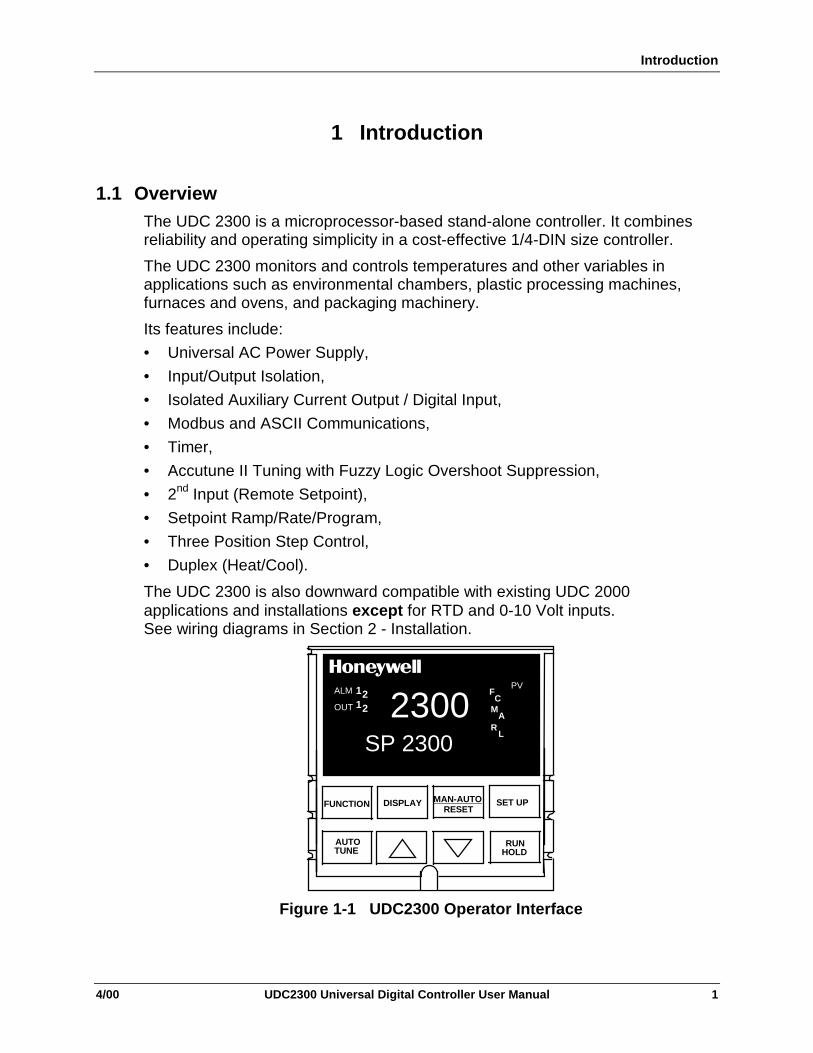
1.1 OverviewThe UDC 2300 is a microprocessor-based stand-alone controller. It combinesreliability and operating simplicity in a cost-effective 1/4-DIN size controller.
The UDC 2300 monitors and controls temperatures and other variables inapplications such as environmental chambers, plastic processing machines,furnaces and ovens, and packaging machinery.
Its features include:
• Universal AC Power Supply,
• Input/Output Isolation,
• Isolated Auxiliary Current Output / Digital Input,
• Modbus and ASCII Communications,
• Timer,
• Accutune II Tuning with Fuzzy Logic Overshoot Suppression,
• 2nd Input (Remote Setpoint),
• Setpoint Ramp/Rate/Program,
• Three Position Step Control,
• Duplex (Heat/Cool).
The UDC 2300 is also downward compatible with existing UDC 2000applications and installations except for RTD and 0-10 Volt inputs.See wiring diagrams in Section 2 - Installation.
ALM
OUT
PVF
FUNCTION
AUTOTUNE
MAN-AUTORESET
SET UP
RUNHOLD
C
RL
1212
SP 2300
2300
DISPLAY
MA
Figure 1-1 UDC2300 Operator Interface
Introduction
2 UDC2300 Universal Digital Controller User Manual 4/00
1.2 CE Conformity (Europe)This product is in conformity with the protection requirements of the followingEuropean Council Directives: 73/23/EEC, the Low Voltage Directive, and89/336/EEC, the EMC Directive. Conformity of this product with any other “CEMark” Directive(s) shall not be assumed.
Product Classification: Class I: Permanently connected, panel-mounted IndustrialControl Equipment with protective earthing (grounding). (EN61010-1).
Enclosure Rating: Panel-mounted equipment, IP 00. This controller must bepanel-mounted. Terminals must be enclosed within the panel. Front panel IP 65(IEC 529).
Installation Category (Overvoltage Category): Category II: Energy-consumingequipment supplied from the fixed installation, local level appliances, andIndustrial Control Equipment. (EN61010-1)
Pollution Degree: Pollution Degree 2: Normally non-conductive pollution withoccasional conductivity caused by condensation. (Ref. IEC 664-1)
EMC Classification: Group 1, Class A, ISM Equipment (EN55011, emissions),Industrial Equipment (EN50082-2, immunity)
Method of EMC Assessment: Technical File (TF)
Declaration of Conformity: 51309602-000
Deviation from the installation conditions specified in this manual, and thespecial conditions for CE conformity in Section 2.1, may invalidate this product’sconformity with the Low Voltage and EMC Directives.

Installation
4/00 UDC2300 Universal Digital Controller User Manual 3
2 Installation
2.1 Overview
Introduction
Installation of the UDC 2300 consists of mounting and wiring the controlleraccording to the instructions given in this section. Read the pre-installationinformation, check the model number interpretation (Appendix B), and becomefamiliar with your model selections, then proceed with installation.
2.2 Preliminary Checks
Introduction
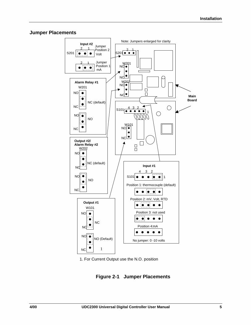
Before you install the controller, remove the chassis and make any preliminarychecks necessary that are listed in Table 2-1. Figure 2-1 shows the locations forjumper placements.
Table 2-1 Preliminary Checks
CheckNumber
Preliminary Check Description
1 Input I Jumper Placement Check the internal jumper for INPUT 1 to makesure it is set for the correct input type. The jumperis located at position S101 on the printed wiringboard. Figure 2-1 shows the location of the jumperand position selections.
2 Optional Input 2 (RSP)Jumper Placement
Check the internal jumper for INPUT 2 to makesure it is set for the correct input type. The jumperis located at position S201 on the printed wiringboard. Figure 2-1 shows the location of the jumperand position selections.
3 Control Relay 1 and CurrentOutput
Check the internal jumper (W101) for CONTROL.The relay is shipped as N.O. (Normally Open).Figure 2-1 shows the location of the jumper andposition selections.
See Table 2-2 for Control Relay contactinformation.
Installation
4 UDC2300 Universal Digital Controller User Manual 4/00
CheckNumber
Preliminary Check Description
4 Control Relay 2 and AlarmRelay Action.
The controller has been shipped with ALARMrelays configured for N.C. (Normally Closed). Ifyou want to change to N.O. refer to Figure 2-1,Jumper positions W201 and W202:
W201 is the ALARM RELAY 1 jumper.
W202 is the jumper for CONTROL RELAY #2 forDuplex Output or 3 position step control and anALARM RELAY 2 for all others.
See Table 2-2 for Control Relay contactinformation, and Table 2-3 for Alarm Relaycontact information.
See Alarm Relay Caution Note, Page 6.
Note: Solid State and open collector Outputs must have jumper set to N.O. (Normally Open).
3 Position Step and Time Duplex must have Output 2-jumper (W202) set to N.O (Normally Open).
Installation
4/00 UDC2300 Universal Digital Controller User Manual 5
Jumper Placements
W201
NO
NC
Alarm Relay #1
NC (default)
NO
NC
NO
W202
NO
NC
Output #2/Alarm Relay #2
NC (default)
NO
NC
NO
W101
NO
NC
Output #1
NC
NO
NC
NO (Default)
S101
4 3 2
1
Input #1
Position 1: thermocouple (default)
Position 2: mV, Volt, RTD
Position 3: not used
Position 4: mA
No jumper: 0 -10 volts
Note: Jumpers enlarged for clarity
S201
W201
2 1
W202
NO
NC
NO
NC
S1014 3 2
1
W101NO
NC
Input #22 1
2 1
Volt
mA
JumperPosition 2
S201
JumperPosition 1
MainBoard
1
1. For Current Output use the N.O. position
Figure 2-1 Jumper Placements
Installation
6 UDC2300 Universal Digital Controller User Manual 4/00
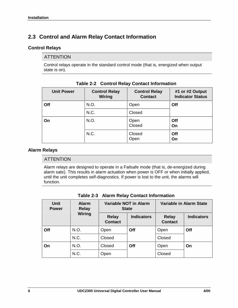
2.3 Control and Alarm Relay Contact Information
Control Relays
ATTENTION
Control relays operate in the standard control mode (that is, energized when outputstate is on).
Table 2-2 Control Relay Contact Information
Unit Power Control RelayWiring
Control RelayContact
#1 or #2 OutputIndicator Status
N.O. OpenOff
N.C. Closed
Off
N.O. OpenClosed
OffOn
On
N.C. ClosedOpen
OffOn
Alarm Relays
ATTENTION
Alarm relays are designed to operate in a Failsafe mode (that is, de-energized duringalarm sate). This results in alarm actuation when power is OFF or when initially applied,until the unit completes self-diagnostics. If power is lost to the unit, the alarms willfunction.
Table 2-3 Alarm Relay Contact Information
Variable NOT in AlarmState
Variable in Alarm StateUnitPower
AlarmRelayWiring
RelayContact
Indicators RelayContact
Indicators
N.O. Open OpenOff
N.C. Closed
Off
Closed
Off
N.O. Closed OpenOn
N.C. Open
Off
Closed
On

Installation
4/00 UDC2300 Universal Digital Controller User Manual 7
2.4 Mounting
Physical Considerations
The controller can be mounted on either a vertical or tilted panel using themounting kit supplied. Adequate access space must be available at the back ofthe panel for installation and servicing activities.
• The controller’s mounting enclosure must be grounded according to CSAstandard C22.2 No. 0.4 or Factory Mutual Class No. 3820 paragraph 6.1.5.
• The front panel is moisture rated NEMA 3/IP65 (IEC) when properly installedwith panel gasket.
Overall Dimensions
96
3.780
96
3.780
Panel Cutout
90 =0.0+0.8
3.5906 +0.03
24
.945
Max PanelThickness
10
.394Max (2)
4.19105.4
.103
2.62 with optionalrear cover
90.73.57
21.0
.826
Dimensions:Millimeters
Inches
20751
3.622 +0.031-0.0
92 -0.0+0.008
3.622 +0.031-0.0
92 -0.0+0.008
Figure 2-2 Mounting Dimensions (not to scale)

Installation
8 UDC2300 Universal Digital Controller User Manual 4/00
Mounting Method
Before mounting the controller, refer to the nameplate on the outside of the caseand make a note of the model number. It will help later when selecting the properwiring configuration.
Panel
20752
Figure 2-3 Mounting Method
Mounting Procedure
Table 2-4 Mounting Procedure
Step Action
1 Mark and cut out the controller hole in the panel according to the dimensioninformation in Figure 2-2.
2 Remove the screw cover and loosen the screw on the front of the controller.Pull the chassis out of the case.
3 Orient the case properly and slide it through the panel hole from the front.
4 Remove the mounting kit from the shipping container and install the kit asfollows:
• Install the screws into the threaded holes of the clips.
• Insert the prongs of the clips into the two holes in the top and bottom of thecase.
• Tighten both screws to secure the case against the panel.
• Carefully slide the chassis assembly into the case, press to close, andtighten the screw. Replace the screw cover.
Installation
4/00 UDC2300 Universal Digital Controller User Manual 9
2.5 Wiring
Electrical Considerations
he controller is considered “rack and panel mounted equipment” per EN61010-1,afety Requirements for Electrical Equipment for Measurement, Control, andaboratory Use, Part 1: General Requirements. Conformity with 72/23/EEC, theow Voltage Directive requires the user to provide adequate protection against ahock hazard. The user shall install this controller in an enclosure that limitsPERATOR access to the rear terminals.
Mains Power Supply
This equipment is suitable for connection to 90 to 264 Vac, 50/60 Hz, powersupply mains. It is the user’s responsibility to provide a switch and non-timedelay (North America), quick-acting, high breaking capacity, Type F (Europe),1/2A, 250V fuse(s), or circuit-breaker, as part of the installation. The switch orcircuit breaker shall be located in close proximity to the controller, within easyreach of the OPERATOR. The switch or circuit breaker shall be marked as thedisconnecting device for the controller.
Controller Grounding
PROTECTIVE BONDING (grounding) of this controller and the enclosure inwhich it is installed shall be in accordance with National and Local electricalcodes. To minimize electrical noise and transients that may adversely affect thesystem, supplementary bonding of the controller enclosure to a local ground,using a No. 12 (4 mm2) copper conductor, is recommended.
Control/Alarm Circuit Wiring
The insulation of wires connected to the Control/Alarm terminals shall be ratedfor the highest voltage involved. Extra Low Voltage (ELV) wiring (input, currentoutput, and low voltage Control/Alarm circuits) shall be separated fromHAZARDOUS LIVE (>30 Vac, 42.4 Vpeak, or 60 Vdc) wiring per PermissibleWiring Bundling, Table 2-5.
Electrical Noise Precautions
Electrical noise is composed of unabated electrical signals, which produceundesirable effects in measurements and control circuits.
Digital equipment is especially sensitive to the effects of electrical noise. Yourcontroller has built-in circuits to reduce the effect of electrical noise from varioussources. If there is a need to further reduce these effects:
• Separate External Wiring—Separate connecting wires into bundles(See Permissible Wiring Bundling - Table 2-5) and route the individualbundles through separate conduit metal trays.

Installation
10 UDC2300 Universal Digital Controller User Manual 4/00
• Use Suppression Devices—For additional noise protection, you may want toadd suppression devices at the external source. Appropriate suppressiondevices are commercially available.
ATTENTION
For additional noise information, refer to Document #51-52-05-01, How to Apply DigitalInstrumentation in Severe Electrical Noise Environments.
Permissible Wiring Bundling
Table 2-5 Permissible Wiring Bundling
Bundle No. Wire Functions1 • Line power wiring
• Earth ground wiring• Control relay output wiring• Line voltage alarm wiring
2 Analog signal wire, such as:• Input signal wire (thermocouple, 4 to 20 mA, etc.)• 4-20 mA output signal wiringDigital input signals
3 • Low voltage alarm relay output wiring• Low voltage wiring to solid state type control circuits
Universal Output Functionality and Restrictions
Table 2-6 Universal Output Functionality and Restrictions
Output/SocketOutput Type Current
OutputRelay #1 Relay #2 Relay #3 Auxiliary Output
Time Simplex 1 N/I Output 1 Alarm 2 Alarm 1 Not NeededTime Simplex 2 N/A N/I Output 1 Alarm 1 Not NeededCurrent Simplex Output N/I Alarm 2 Alarm 1 Not NeededTime Duplex orTPSC
N/I Output 1 Output 2 Alarm 1 Not Needed
Current Dup. 100 % Output 1 N/I Alarm 2 Alarm 1 Not NeededCurrent Dup. 50 % Output 1 N/I Alarm 2 Alarm 1 Output 2Current/Time Output 1 N/I Output 2 Alarm 1 Not NeededTimer/Current Output 2 N/I Output 1 Alarm 1 Not Needed
N/I = Not Installed
N/A = The output form or the individual output is Not Available or is not used for this output form.
Not Needed =Auxiliary Output is not needed to provide the desired output function and can be used foranother purpose. Auxiliary Output could also be used as a substitute for current Output 1.
Installation
4/00 UDC2300 Universal Digital Controller User Manual 11
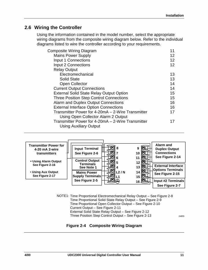
2.6 Wiring the ControllerUsing the information contained in the model number, select the appropriatewiring diagrams from the composite wiring diagram below. Refer to the individualdiagrams listed to wire the controller according to your requirements.
Composite Wiring DiagramMains Power SupplyInput 1 ConnectionsInput 2 ConnectionsRelay Output
ElectromechanicalSolid StateOpen Collector
Current Output ConnectionsExternal Solid State Relay Output OptionThree Position Step Control ConnectionsAlarm and Duplex Output ConnectionsExternal Interface Option ConnectionsTransmitter Power for 4-20mA – 2-Wire Transmitter
Using Open Collector Alarm 2 OutputTransmitter Power for 4-20mA – 2-Wire Transmitter
Using Auxiliary Output
11121212
131314141515161617
17
910111213
141516
7654L2 / NL1
8Input TerminalSee Figure 2-6
Control OutputTerminalsSee Note 1
Mains Power Supply Terminals
See Figure 2-5 Input #2 TerminalsSee Figure 2-7
External InterfaceOptions TerminalsSee Figure 2-15
Alarm andDuplex OutputConnectionsSee Figure 2-14
24855
Transmitter Power for4-20 mA 2-wire
transmitters
• Using Alarm Output See Figure 2-16
• Using Aux Output See Figure 2-17
Time Proportional Electromechanical Relay Output – See Figure 2-8Time Proportional Solid State Relay Output – See Figure 2-9Time Proportional Open Collector Output – See Figure 2-10Current Output – See Figure 2-11External Solid State Relay Output – See Figure 2-12Three Position Step Control Output – See Figure 2-13
NOTE1:
Figure 2-4 Composite Wiring Diagram

Installation
12 UDC2300 Universal Digital Controller User Manual 4/00
L2 / NL1
Neutral
Mainspowersupply
Hot
Ground
1
2
24856
PROTECTIVE BONDING (grounding) of this controllerand the enclosure in which it is installed, shall be inaccordance with National and Local electrical codes. Tominimize electrical noise and transients that mayadversely affect the system, supplementary bonding ofthe controller enclosure to a local ground, using a No.12 (4 mm2) copper conductor, is recommended.Before powering the controller, see “PreliminaryChecks” in this section of the user manual forswitch and jumper settings.
1
2 Provide a switch and non-time delay (North America),quick-acting, high breaking capacity, type F (Europe),1/2 A, 250 V fuse(s), or circuit-breaker as part of theinstallation.
Figure 2-5 Mains Power Supply
8
7
6 R
+
-
mV, Volts (except 0-10V),Milliamperes, or RadiamaticThermocouple
PlatinumRTD
24857
8
7
6 R
+
-mV, Volt,
orMilliampere
Source
8
7
6R
+
-
0 to 10 Volts
The voltage divider for 0 to 10Volts is supplied with thecontroller when the input isspecified. You must install itwhen you wire the controllerbefore start-up. 1
VoltSource
876
+_
R_
+ 1
2
3
1 These inputs are wired differently than the UDC2000
RTD1
UseThermocoupleextension wireonly
Figure 2-6 Input 1 Connections
1516
+ 0 to 20 mA,4 to 20 mA,0 to 5 Volts1 to 5 Volts
_
24858
See “Preliminary Checks” in thissection of the User Manual forjumper selections.
Figure 2-7 Input 2 Connections

Installation
4/00 UDC2300 Universal Digital Controller User Manual 13
1 Control relays 1 and 2 are configured N.O. as shipped. Alarm relays1 and 2 are configured N.C. as shipped. N.O. or N.C. configurationsare selectable by jumpers on the Main printed wiring boards.See “Preliminary Checks” in this section of theUser Manual for details. Each SPST relay is rated at 5A, 120Vac and 30 Vdc, 2.5 A 240 Vac. User-provided fuses should be sizedaccordingly. For solid state relay outputs, see Figure 2-12.
24859
1
5
4
LoadSupplyPower
5 amp Fast Blo
Control Relay #1Load
OUT1 OUT2/ALM2
9
10
See Figure 2-14 for Alarm and Duplex Output Connections.See Table 2-2 and Table 2-3 for Control and Alarm Relay Contact information.
Figure 2-8 Electromechanical Relay Output
If the load current is less than the minimum rated value of 20 mA,there may be a residual voltage across both ends of the load evenif the relay is turned off. Use a dummy resistor as shown tocounteract this. The total current through the resistor and the loadcurrent must exceed 20 mA.
2
1
Solid State relay is rated at 1 Amp at 25°C, linearly derated to 0.5Amp at 55°C. Customer should size fuse accordingly.
54
ACLoadPowerSupply
Dummy Resistor
2
1 24860
Control Relay #1Load
1 amp Fast Blo OUT1 OUT2/ALM2
9
10
See Figure 2-14 for Alarm and Duplex Output Connections.
See Table 2-2 and Table 2-3 for Control and Alarm Relay Contactinformation.
Figure 2-9 Solid State Relay Output

Installation
14 UDC2300 Universal Digital Controller User Manual 4/00
CAUTION Open collector outputs are internally powered at 24 Vdc.Connecting an external supply will damage the controller.External relays should be fused between power and relay load.
1
24861M
Customer Supplied External Solid State Relay
5 –4++
–1
0-24 Vdc
Customer Supplied External Electromechanical Relay
5–4+
1
+
–
0-24 Vdc
See Figure 2-14 for Alarm and Duplex Output Connections.
See Tables 2-2 and 2-3 for Control and Alarm Relay Contact information.
OUT1 OUT2/ALM2
9 –10+
OUT2/ALM2
9 –10+
OUT1
Figure 2-10 Open Collector Relay Output
Installing a current output instrumentinto a case wired for relay outputswill damage the instrument.
CAUTION54
Controller Load
0 to 750 Ohms
+-
24862
1
Connect shield to ground at one end only.
3 Set output jumper per Figure 2-2.
Currentoutput4 to 20 mA
2
1
2
See Figure 2-14 for Alarm and Duplex Output Connections.
See Table 2-2 and Table 2-3 for Control and Alarm Relay Contactinformation.
Figure 2-11 Current Output
Installation
4/00 UDC2300 Universal Digital Controller User Manual 15
10 Amp Solid StateRelay Assembly
5-4+L2 / NL1
LOAD
L1/H
L2/N
+ -
Green
WhiteBlack
Relay Assembly
24863M
AC
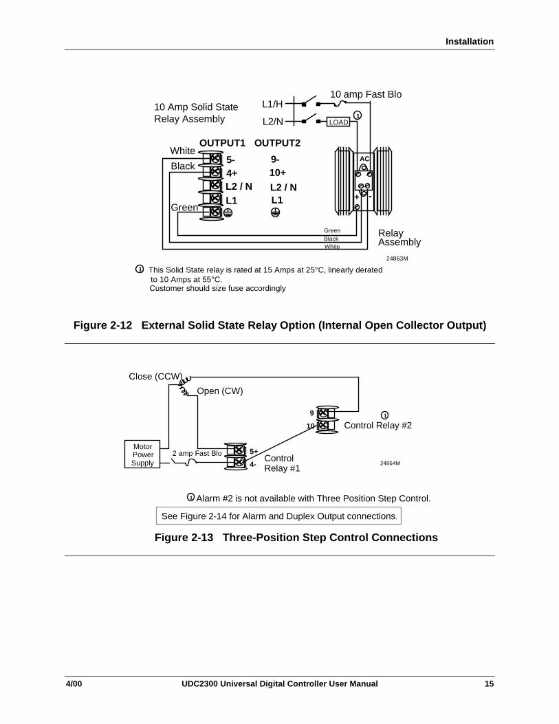
This Solid State relay is rated at 15 Amps at 25°C, linearly derated to 10 Amps at 55°C. Customer should size fuse accordingly
1
1
10 amp Fast Blo
Green
Black
WhiteOUTPUT1 OUTPUT2
9-10+
L2 / NL1
Figure 2-12 External Solid State Relay Option (Internal Open Collector Output)
9
10
5+
4-
Control Relay #2
Motor Power Supply
Close (CCW)
Open (CW)
Control Relay #1
24864M
Alarm #2 is not available with Three Position Step Control.1
1
2 amp Fast Blo
See Figure 2-14 for Alarm and Duplex Output connections.
Figure 2-13 Three-Position Step Control Connections

Installation
16 UDC2300 Universal Digital Controller User Manual 4/00
9
10
11
12
1 2LoadSupplyPower
Control or AlarmRelay #2 Load
AlarmRelay #1 Load
LoadSupplyPower
5 amp fast Blo
5 amp Fast Blo
24867
Control relays 1 and 2 are configured N.O. as shipped. Alarm relays 1and 2 are configured N.C. as shipped. N.O. or N.C. configurations areselectable by jumpers on main printed wiring boards. See “PreliminarChecks” in this sections of the User Manual for details. Each SPSTrelay is rated at 5 A, 120 Vac and 30 Vdc, 2.5 A, 240 Vac.
Alarm #2 not available for Time Proportional Duplex or Three PositionStep Control.
1
1
2
Figure 2-14 Alarm and Duplex Output Connections
1314
+_
AuxiliaryLoad
0 - 500 Ω
Connect shieldto ground at oneend only.
1
1 AuxOut , Digital Input and Communications are mutually exclusive.
Auxiliary Output
1314
+_
ContactInput
Switch
Connect shieldto ground at oneend only.
Digital Inputs 1
1Communications
13
14
D–
D+
COMMUNICATION MASTER
(A) (RTN) (B)
D+ SHLD D–
120 OHMS
TO OTHER COMMUNICATION
CONTROLLERS
D+D–
120 OHMS ON LAST LEG
Connect shield wires together with Honeywell supplied crimp part number 30755381-001
1
2 Do not run these lines in the same conduit as AC power.
1
2
21758B.ppt
Figure 2-15 External Interface Option Connections

Installation
4/00 UDC2300 Universal Digital Controller User Manual 17
2 Wire Transmitter
Configure:A2S1TYPE = NONEA2S2TYPE = NONE
_
+8 +7 -
9 –10+
INPUT 1 OUTPUT 2
Figure 2-16 Transmitter Power for 4-20 mA — 2 wire Transmitter Using OpenCollector Alarm 2 Output (Model DC230B-XT-XX-XX-XXXXXXX-XX-X)
2 Wire Transmitter
Configure: AUXOUT = OUTAuxiliary Output Calibration ZEROVAL = 4095 SPANVAL = 4095
_
+8 +7 -
13 +14 -
INPUT 1
AUXOUT
Figure 2-17 Transmitter Power for 4-20 mA — 2 Wire TransmitterUsing Auxiliary Output (Model DC230B-XX-2X-XX-XXXXXXX-XX-X)
2.7 Initial Start-up
Overview
This section gives you the information necessary to start up your controller priorto configuration. Review the Operator Interface portion (Subsection 2.8) to makesure you are familiar with the indicator definitions and key functions.
Apply Power
When power is applied, the controller will run three diagnostic tests. After thesetests are completed, “TEST DONE” is displayed.

Installation
18 UDC2300 Universal Digital Controller User Manual 4/00
Test Failures
If one or more of these tests fail, the controller will go to the Failsafe ManualMode, and FAILSF will flash in the lower display and a message indicating whichtest failed will appear in the lower display. Then, “DONE” will appear in the lowerdisplay.
2.8 Operator Interface and Key Functions
ALM
OUT
PVF
FUNCTION
AUTOTUNE
MAN-AUTO RESET
SET UP
RUN HOLD
ALM - Alarmconditions existOUT - ControlRelay1 or 2 on
Keys
C
RL
1212
SP 23002300
DISPLAY
MA
M or A - Manual/Auto display
F - °Fahrenheit being used
C - °Centigrade being used
R - Remote or Local SP2 setpoint active
L - Local setpoint active
Upper Display - Four digits• Normal operation - Process Variable• Configuration mode - displays parameter value or selection
Lower Display - Six alphanumeric characters• Normal operation – display is blank unless configured For default prompt of PV or Setpoint• Configuration mode - displays functions and parameters
Selects Manual or Auto mode.Resets the latching Limit Controller relay.In Set Up mode, used to restore original value orselection.
FUNCTIONSelects functions within each configuration group.Selects 2nd Setpoint or Remote Setpoint.
DISPLAYReturns Controller to normal display from Set Upmode.Toggles various operating parameters for display.
MAN-AUTO RESET
SET UP Scrolls through the configuration Setup groups.
AUTOTUNE
HOLDEnables Run/Hold of the SP Ramp or Programplus Timer start.
Decreases setpoint or output value. Decreases theconfiguration values or changes functions in Configurationmode groups.
Increases setpoint or output value. Increases theconfiguration values or changes functions in Configurationmode groups.
Initiates Limit Cycle Tuning (Accutune).
24868
RUN
• TUNE- Accutune in progress
Figure 2-18 Operator Interface and Key Functions
Key Error Message
When a key is pressed and the prompt KEYERR appears in the lower display, itwill be for one of the following reasons:
• parameter is not available,• not in Set Up mode, press SET UP key first,• key malfunction.
Configuration
4/00 UDC2300 Universal Digital Controller User Manual 19
3 Configuration
3.1 Overview
Introduction
Configuration is a dedicated operation where you use straightforward keystrokesequences to select and establish (configure) pertinent control data best suitedfor your application.
To assist you in the configuration process, there are prompts that appear in theupper and lower displays. These prompts let you know what group ofconfiguration data (Set Up prompts) you are working with and also, the specificparameters (Function prompts) associated with each group.
Figure 3-1 shows you an overview of the prompt hierarchy as they appear in thecontroller.
As you will see, the configuration data is divided into 11 main Set Up groups plusprompts for calibration and prompts that show the status of the continuousbackground tests that are being performed.
3.2 Configuration Procedure
IntroductionEach of the Set Up groups and their functions are pre-configured at the factory.The factory settings are shown in Table 3-2 through Table 3-12 that follow thisprocedure.If you want to change any of these selections or values, follow the procedure inTable 3-1 Configuration Procedure. This procedure tells you the keys to pressto get to any Set Up group and any associated Function parameter prompt.Record your selections on the Configuration Record Sheet found in Section 8 –Appendix C.

Configuration
20 UDC2300 Universal Digital Controller User Manual 4/00
Figure 3-1 Prompt Hierarchy
Set Up Group Function Prompts
TIMER TIMER PERIOD START L DISP RESET INCRMT
TUNING PB orGAIN
RATE T I MIN orI RPM
MANRST PB 2 orGAIN 2
RATE2T I2 MIN orI2 RPM
CYC T1or
CT1 X3
CYC2T2or
CT2 X3
SECUR LOCK AUTOMA A TUNE RN HLD SP SL
SPRAMP SPRAMP TI MIN FINLSP SPRATE EUHRUP EUHRDN SPPROG STRSEG
ENDSEG RPUNIT RECYCL SOKDEV PG END STATE ToBEGN PVSTRT
SGx RP* SGxSP* SGx TI* * x = 1 to 12. Program concludes after segment 12
ATUNE FUZZY TUNE AT ERR
ALGOR CTRALG OUTALG 4-20RG RLY TYP
INPUT1 DECMAL UNITS IN1TYP XMITR1 IN1 HI IN1 LO RATIO1 BIAS 1
FILTR1 BRNOUT EMISS FREQ DISPLY LNGUAG
INPUT2 IN2TYP XMITR2 IN2 HI IN2 LO RATIO2 BIAS 2 FILTR2
CONTRL PIDSET SW VAL LSP’S RSP SRC SP TRK PWR UP PWROUT SP Hi
SP Lo ACTION OUT Hi OUT Lo D BAND HYST FAILSF FSMODE
PBorGN MINRPM
OPTIONS AUXOUT 0 PCT 100 PCT DIG IN DI COM
COM ComSTA ComADD SDENAB SHDTIM PARITY BAUD WS_FLT TXDLY
SDMODE SHD_SP UNITS CSRATO CSP_BI LOOPBK
ALARMS A1S1VA A1S2VA A2S1VA A2S2VA A1S1TY A1S2TY A2S1TY A2S2TY
A1S1HL A1S1EV A1S2HL A1S2EV A2S1HL A2S1EV A2S2HL A2S2EV
ALHYST ALARM1 BLOCK
STATUS VERSON FAILSF TESTS

Configuration
4/00 UDC2300 Universal Digital Controller User Manual 21
Procedure
ATTENTION
The prompting scrolls at a rate of 2/3 seconds when the SET UP or FUNCTION key is held in.Also, [] [] keys will move group prompts forward or backward at a rate twice as fast.
Table 3-1 Configuration Procedure
Step Operation Press Result
1 Enter Set UpMode
SET UP Upper Display = SET
Lower Display = TIMER (This is the first Set UpGroup title)
2 Select any SetUp Group
SET UP Sequentially displays the other Set Up group titles.
You can also use the [] [] keys to scan the SetUp groups in both directions. Stop at the Set Upgroup title that describes the group of parametersyou want to configure. Then proceed to the nextstep.
3 Select aFunctionParameter
FUNCTION Upper Display = the current value or selection for thefirst function prompt of the selected Set Up group.
Lower Display = the first Function prompt within thatSet Up group.
Sequentially displays the other function prompts ofthe Set Up group you have selected. Stop at thefunction prompt that you want to change, thenproceed to the next step.
4 Change theValue orSelection
[] [] Increments or decrements the value or selection thatappears for the selected function prompt. If youchange the value or selection of a parameter while inSet Up mode then decide not to enter it, press [MAN-AUTO/RESET] once—the original value or selectionis recalled.
5 Enter the Valueor Selection
FUNCTION Enters value or selection made into memory afteranother key is pressed.
6 ExitConfiguration
DISPLAY Exits configuration mode and returns controller to thesame state it was in immediately preceding entry intothe Set Up mode. It stores any changes you havemade.If you do not press any keys for 30 seconds, thecontroller times out and reverts to the mode anddisplay used prior to entry into Set Up mode.

Configuration
22 UDC2300 Universal Digital Controller User Manual 4/00
3.3 Timer Set Up Group
Introduction
The Timer Set Up group allows you to configure a time-out period and to selectthe timer start by either the keyboard (RUN/HOLD key) or Alarm 2. The optionaldigital input can also be configured to start the timer. The timer display isselectable as either “time remaining” (see TREM) or “elapsed time” (see ET).
Alarm 1 is activated at the end of the time-out period. When the timer is enabled,it has exclusive control of the alarm 1 relay—any previous alarm 1 configurationis ignored. At time-out, the timer is ready to be activated again by whateveraction has been configured.
Function Prompts
Table 3-2 TIMER Group (Numeric Code 100) Function Prompts
Prompt Selection or Range of Setting
English NumericCode
Description
NumericCode
English
FactorySetting
TIMER 101 Enable orDisable Timer
01
DISENAB
DIS
PERIOD 102 Time-out Period 0:00 to 99:59Select length of time inHours and Minutes, orMinutes and Seconds.
0:01
START 103 Timer FunctionStart
01
KEY (Run/Hold key)AL2 (Alarm 2)
KEY
L DISP 104 Timer Display 01
TREM (time remaining)ET (elapsed time)
TREM
RESET 105 Timer ResetControl
01
KEY (Run/Hold key)AL1 (Alarm 1 or Key)
KEY
INCRMT 106 Timer CountIncrement
01
MIN (Counts HR/MIN)SEC (Counts MIN/SEC)
MIN

Configuration
4/00 UDC2300 Universal Digital Controller User Manual 23
3.4 Tuning Set Up Group
Introduction
Tuning consists of establishing the appropriate values for the tuning constantsyou are using so that your controller responds correctly to changes in processvariable and setpoint. You can start with predetermined values but you will haveto watch the system to see how to modify them. The Accutune featureautomatically selects Gain, Rate, and Reset on demand.
ATTENTION
Because this group contains functions that have to do with security and lockout, werecommend that you configure this group last, after all other configuration data hasbeen loaded.
Function Prompts
Table 3-3 TUNING Group (Numeric Code 200) Function Prompts
Prompt Selection or Range of Setting
English NumericCode
Description
NumericCode
English
FactorySetting
PB orGAIN
201 ProportionalBand or Gain
PB = 0.1 to 1000 %Gain = 0.01 to 1000
1.0
RATE T 202 Rate in Minutes 0.00 to 10.00 minutes0.08 or less = OFF
0.00
I MINorI RPM
203 Reset inminutes/repeatReset inrepeats/minute
0.02 to 50.00
0.02 to 50.00
1.0
1.0
MANRST 204 Manual Reset -100 to 100 % Output 0.0
PB 2 orGAIN 2
205 ProportionalBand 2 or Gain2
PB = 0.1 to 1000 %Gain = 0.01 to 1000
1.0
RATE2T 206 Rate 2 inMinutes
0.00 to 10.00 minutes0.08 or less = OFF
0.00
I2 MINorI2 RPM
207 Reset inminutes/repeatReset inrepeats/minute
0.02 to 50.00
0.02 to 50.00
1.0
1.0
Table continued next page

Configuration
24 UDC2300 Universal Digital Controller User Manual 4/00
Table 3-3 TUNING Group (Numeric Code 200) Function Prompts, continued
Prompt Selection or Range of Setting
English NumericCode
Description
NumericCode
English
FactorySetting
CYC T1 orCT1X3
208 Cycle Time (Heat)Cycle times are ineither second or1/3 secondincrementsdepending uponthe configurationof RLY TYP in the“Algorithm” SetUp group.
1 to 120 20
CYC2T2orCT2 X3
209 Cycle Time (Cool)Cycle times are ineither second or1/3 secondincrementsdepending uponthe configurationof RLY TYP in the“Algorithm” SetUp group.
1 to 120 20
SECUR 210 Security Code 0 to 4095 0
LOCK 211 Lockout 01234
NONECALCONFVIEWALL
CAL
AUTOMA 212 Auto/Manual KeyLockout
01
DISENAB
ENAB
A TUNE 213 Autotune KeyLockout
01
DISENAB
ENAB
RN HLD 214 Run/Hold KeyLockout
01
DISENAB
ENAB
SP SEL 215 Setpoint SelectFunction Lockout
01
DISENAB
ENAB

Configuration
4/00 UDC2300 Universal Digital Controller User Manual 25
3.5 SP Ramp Set Up Group
IntroductionA single setpoint ramp [SPRAMP] can be configured to occur between thecurrent local setpoint and a final local setpoint over a time interval of from 1 to255 minutes.SPRATE lets you configure a specific rate of change for any local setpointchange.You can also configure a 12-segment program from a Ramp/Soak profile.You can start and stop the ramp/program using the RUN/HOLD key.PV Hot Start is standard and means that at power up, the setpoint is set to thecurrent PV value and the Ramp or Rate or Program then starts from this value.
Function Prompts
Table 3-4 SPRAMP Group (Numeric Code 300) Function Prompts
Prompt Selection or Range of Setting
English NumericCode
Description
NumericCode
English
FactorySetting
SP RAMP 301 Single SetpointRampRate and Programmust be disabled
01
DISENAB
DIS
TI MIN 301 Single SetpointRamp Time
0 to 255 Minutes 3
FINLSP 302 Setpoint Ramp FinalSetpoint
Enter a value within thesetpoint limits
1000
SPRATE 304 Setpoint RateRamp and Programmust be disabled
01
DISENAB
DIS
EUHRUP 305 Rate Up 0 to 9999 in Engineeringunits per hour
0
EUHRDN 306 Rate Down 0 to 9999 in Engineeringunits per hour
0
SPPROG 307 Setpoint Ramp/SoakProgrammingRate and Rampmust be disabled
01
DISENAB
DIS
STRSEG 308 Start SegmentNumber
1 to 11 - - -
Table continued next page
Configuration
26 UDC2300 Universal Digital Controller User Manual 4/00
Prompt Selection or Range of Setting
English NumericCode
Description
NumericCode
English
FactorySetting
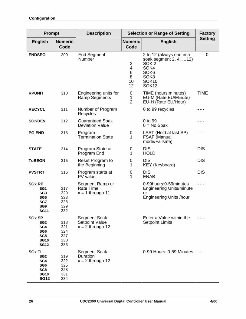
ENDSEG 309 End SegmentNumber
2468
1012
2 to 12 (always end in asoak segment 2, 4, …12)SOK 2SOK4SOK6SOK8SOK10SOK12
0
RPUNIT 310 Engineering units forRamp Segments
012
TIME (hours:minutes)EU-M (Rate EU/Minute)EU-H (Rate EU/Hour)
TIME
RECYCL 311 Number of ProgramRecycles
0 to 99 recycles - - -
SOKDEV 312 Guaranteed SoakDeviation Value
0 to 990 = No Soak
- - -
PG END 313 ProgramTermination State
01
LAST (Hold at last SP)FSAF (Manualmode/Failsafe)
- - -
STATE 314 Program State atProgram End
01
DISHOLD
DIS
ToBEGN 315 Reset Program tothe Beginning
01
DISKEY (Keyboard)
DIS
PVSTRT 316 Program starts atPV value
01
DISENAB
DIS
SGx RPSG1SG3SG5SG7SG9SG11
317320323326329332
Segment Ramp orRate Timex = 1 through 11
0-99hours:0-59minutesEngineering Units/minuteorEngineering Units /hour
- - -
SGx SPSG2SG4SG6SG8SG10SG12
318321324327330333
Segment SoakSetpoint Valuex = 2 through 12
Enter a Value within theSetpoint Limits
- - -
SGx TISG2SG4SG6SG8SG10SG12
319322325328331334
Segment SoakDurationx = 2 through 12
0-99 Hours: 0-59 Minutes - - -

Configuration
4/00 UDC2300 Universal Digital Controller User Manual 27
3.6 Accutune Set Up Group
Introduction
Accutune II automatically calculates GAIN, RATE, and RESET TIME (PID)tuning constants for your control loop. When initiated on demand, the Accutunealgorithm measures a process step response and automatically generates thePID tuning constants needed for no overshoot on your process.Fuzzy Overshoot Suppression, when enabled, will suppress or eliminate anyovershoot that may occur as a result of the existing tuning parameters, as the PVapproaches the setpoint.
Function Prompts
Table 3-5 ATUNE Group (Numeric Code 400) Function Prompts
Prompt Selection or Range of Setting
English NumericCode
Description
NumericCode
English
FactorySetting
FUZZY 401 FuzzyOvershootSuppression
01
DISENAB
DIS
TUNE 402 DemandTuning
01
DISTUNE
TUNE
AT ERR 403 Accutune ErrorCodes (ReadOnly)
0345
NONEIDFLABRTRUN
- - -
Configuration
28 UDC2300 Universal Digital Controller User Manual 4/00
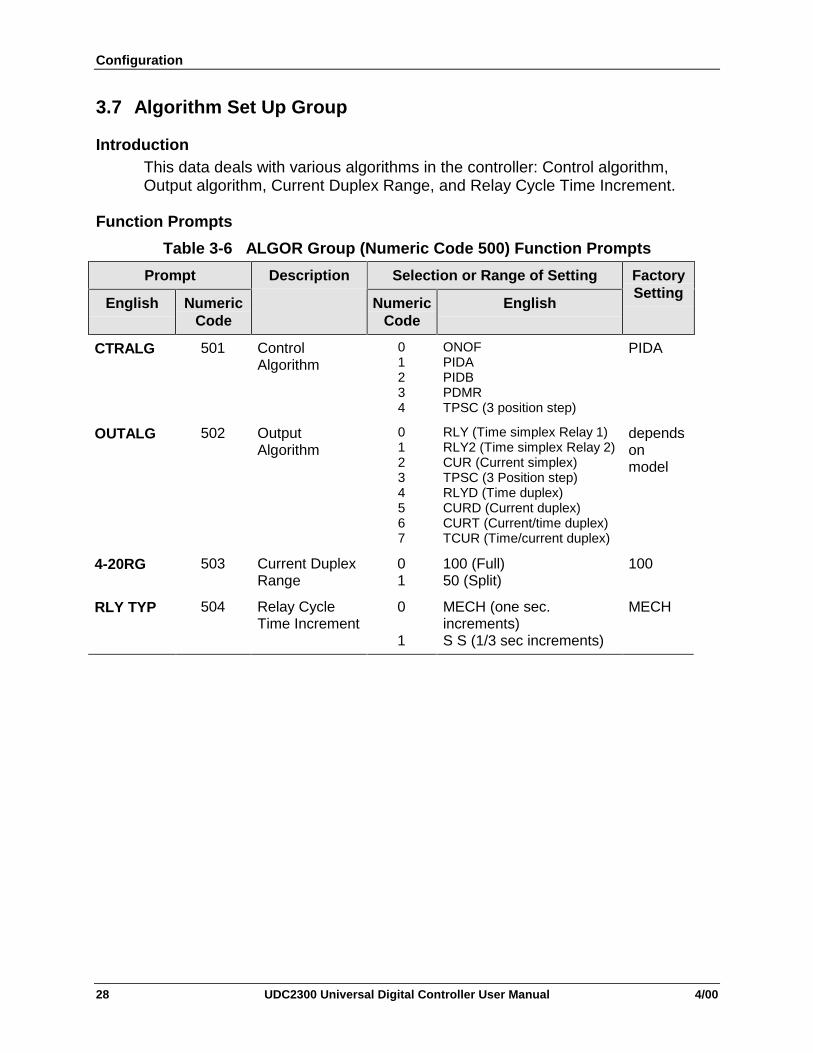
3.7 Algorithm Set Up Group
IntroductionThis data deals with various algorithms in the controller: Control algorithm,Output algorithm, Current Duplex Range, and Relay Cycle Time Increment.
Function Prompts
Table 3-6 ALGOR Group (Numeric Code 500) Function Prompts
Prompt Selection or Range of Setting
English NumericCode
Description
NumericCode
English
FactorySetting
CTRALG 501 ControlAlgorithm
01234
ONOFPIDAPIDBPDMRTPSC (3 position step)
PIDA
OUTALG 502 OutputAlgorithm
01234567
RLY (Time simplex Relay 1)RLY2 (Time simplex Relay 2)CUR (Current simplex)TPSC (3 Position step)RLYD (Time duplex)CURD (Current duplex)CURT (Current/time duplex)TCUR (Time/current duplex)
dependsonmodel
4-20RG 503 Current DuplexRange
01
100 (Full)50 (Split)
100
RLY TYP 504 Relay CycleTime Increment
0
1
MECH (one sec.increments)S S (1/3 sec increments)
MECH

Configuration
4/00 UDC2300 Universal Digital Controller User Manual 29
3.8 Input 1 Set Up Group
Function Prompts
Table 3-7 INPUT1 Group (Numeric Code 600) Function Prompts
Prompt Selection or Range of Setting
English NumericCode
Description
NumericCode
English
FactorySetting
DECMAL 601 Decimal PointSelection
012
8888 (none)888.888.88
8888
UNITS 602 TemperatureUnits
120
FCNONE
F
Numeric English Numeric English
IN1TYP 603 Input 1 ActuationType
123456789
10111213141516
BE HE LJ HJ LK HK L
NNMHNNMLN90HN90LNICRS
T HT L
17181920212223242526272829303133
W HW L100H100L200500
RADHRADI0-204-2010m50m0-51-5
0-10100m
K H
Numeric English Numeric English
XMITR1 604 TransmitterCharacterization
0123456789
101112
BE HE LJ HJ LK HK L
NNMHNNMLN90HN90LNICR
13141516171819202122232425
ST HT LW HW L100H100L200500
RADHRADILINSrT
LIN

Configuration
30 UDC2300 Universal Digital Controller User Manual 4/00
Table 3-7 INPUT1 Group (Numeric Code 600) Function Prompts, continued
Prompt Selection or Range of Setting
English NumericCode
Description
NumericCode
English
FactorySetting
IN1 HI 605 Input 1 HighRange Value
−999 to 9999 floatingin engineering units
2400
IN1 LO 606 Input 1 LowRange Value
−999 to 9999 floatingin engineering units
0
RATIO1 607 Ratio on Input 1 -20.0 to 20.0 1.00
BIAS 1 608 Bias on Input 1 -999 to 9999 0.0
FILTR1 609 Filter for Input 1 0 to 120 seconds0 = No Filter
1.0
BRNOUT 610 BurnoutProtection(Sensor Break)
0123
NONEUP (Upscale)DOWN (Downscale)NOFS (No Failsafe)
UP
EMISS 611 Emissivity 0.01 to 1.00 (RADH &RADI only)
1.0
FREQ 612 Power LineFrequency
01
6050
60
DISPLY 613 Default Display(Single Displaymodels only)
012
SP (Setpoint)PRY ( PV with Label)PRN (PV without Label)
PRN
LNGUAG 614 LanguageSelection
012345
ENGLFRENGERMSPANITALNUMB (Numeric)
ENGL
Configuration
4/00 UDC2300 Universal Digital Controller User Manual 31
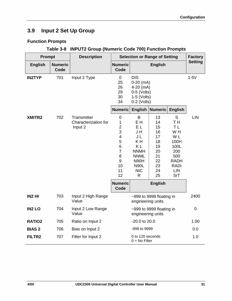
3.9 Input 2 Set Up Group
Function Prompts
Table 3-8 INPUT2 Group (Numeric Code 700) Function Prompts
Prompt Selection or Range of Setting
English NumericCode
Description
NumericCode
English
FactorySetting
IN2TYP 701 Input 2 Type 02526293034
DIS0-20 (mA)4-20 (mA)0-5 (Volts)1-5 (Volts)0-2 (Volts)
1-5V
Numeric English Numeric English
XMITR2 702 TransmitterCharacterization for Input 2
0123456789
101112
BE HE LJ HJ LK HK L
NNMHNNMLN90HN90LNICR
13141516171819202122232425
ST HT LW HW L100H100L200500
RADHRADILINSrT
LIN
NumericCode
English
IN2 HI 703 Input 2 High RangeValue
−999 to 9999 floating inengineering units
2400
IN2 LO 704 Input 2 Low RangeValue
−999 to 9999 floating inengineering units
0
RATIO2 705 Ratio on Input 2 -20.0 to 20.0 1.00
BIAS 2 706 Bias on Input 2 -999 to 9999 0.0
FILTR2 707 Filter for Input 2 0 to 120 seconds0 = No Filter
1.0

Configuration
32 UDC2300 Universal Digital Controller User Manual 4/00
3.10 Control Set Up Group
IntroductionThe functions listed in this group deal with how the controller will control theprocess including: Number of Tuning Parameter Sets, Setpoint Source, Tracking,Power-up Recall, Setpoint Limits, Output Direction and Limits, Deadband, andHysteresis.
Function Prompts
Table 3-9 CONTRL Group (Numeric Code 800) Function Prompts
Prompt Selection or Range of Setting
English NumericCode
Description
NumericCode
English
FactorySetting
PIDSET 801 Number of TuningParameter Sets
0123
ONE2KBD (Keyboard)2 PR (PV switch)2 SP (SP switch)
ONE
SW VAL 802 Automatic SwitchoverValue
Value in engineering unitswithin PV or SP range limits
0.00
LSP’S 803 Local Setpoint Source 01
ONETWO
ONE
RSPSRC 804 Remote SetpointSource
01
NONEINP2
NONE
SP TRK 805 Setpoint Tracking 01
2
NONEPROC (LSP tracks PV–manual)RSP (LSP tracks RSP–auto)
NONE
PWR UP 806 Power Up ControllerMode Recall
01234
MAN (Manual/LSP/Failsafe)ALSP (Auto/last LSP)ARSP (Auto/last RSP)AMSP (Last mode/last SP)AMLS (Last mode/last LSP)
ALSP
PWROUT 807 TPSC (Three PositionStep Control) OutputStart-up Mode
01
LAST (Last output)FSAF (Failsafe output)
LAST
SP Hi 808 Setpoint High Limit 0 to 100 % of the PV range 2400
SP Lo 809 Setpoint Low Limit 0 to 100 % of the PV range 0
ACTION 810 Control OutputDirection
01
DIRREV
REV
Table continued next page

Configuration
4/00 UDC2300 Universal Digital Controller User Manual 33
Table 3-9 CONTRL Group (Numeric Code 800) Function Prompts, continued
Prompt Selection or Range of Setting
English NumericCode
Description
NumericCode
English
FactorySetting
OUT Hi 811 High OutputLimit
-5 to 105 % of Output(Current)
0.0 to 100.0 % of Output(Relay)
100
OUT Lo 812 Low OutputLimit
-5 to 105 % of Output(Current)
0.0 to 100.0 % of Output(Relay)
0
D BAND 813 Deadband -5 to 25.0 % (Time Duplex)
0.5 to 5.0 % (3 position step)
2.0
HYST 814 Hysteresis(Output RelayOnly)
0.0 to 100.0 % of PV 0.5
FAILSF 815
816
Failsafe OutputValue
01
0 to 100 %
For 3 Position Step0 (Closed position)100 (Open position)
0.0
FSMODE 817 Failsafe Mode 0
1
No L (Mode does not clearonce unit goes to FS Output)LACH (Unit goes to manualand FS output)
NO_L
PBorGN 818 ProportionalBand Units
01
GAINPB
GAIN
MINRPM 819 Reset Units 01
MINRPM
MIN

Configuration
34 UDC2300 Universal Digital Controller User Manual 4/00
3.11 Options Set Up Group
Function PromptsTable 3-10 Options Group (Numeric Code 900) Function Prompts
Prompt Selection or Range of Setting
English NumericCode
Description
NumericCode
English
FactorySetting
AUXOUT 901 AuxiliaryOutput
01234567
DIS DisabledIN1 Input 1IN2 Input 2PROC Process VariableDEV DeviationOUT OutputSP SetpointLSP1 Local Setpoint 1
DIS
0 PCT 902 AuxiliaryOutput LowScaling Factor
Value in Engineering Units 0
100 PCT 903 AuxiliaryOutput HighScaling Factor
Value in Engineering Units 100
DIG IN 904 Digital Input 01234567
8910
11121314151617
NoneMAN To ManualLSP To Local SP 1SP2 To Local SP 2DIR Direct ControlHOLD Hold SPP/SP RampPID2 PID Set 2RUN Start a stopped
SPP/SP RampBegn SPP ResetNO I Inhibit IntegralMNFS Manual, Failsafe
OutputLOCK Keyboard DisableTIMR Start TimerTUNE Start TuneINIT Init SP to PVRSP Remote SPMNLT Latching ManualTRAK Output tracks Input 2
NONE
DI COM 905 Digital InputCombinations
012345
DIS Disabled+ PD2 PID Set 2+DIR Direct+SP2 Set Point 2+SP1 Set Point 1+RUN Start SPP
DIS

Configuration
4/00 UDC2300 Universal Digital Controller User Manual 35
3.12 Communications Set Up Group
Function Prompts
Table 3-11 Communications Group (Numeric Code 1000)
Prompt Selection or Range of Setting
English NumericCode
Description
NumericCode
English
FactorySetting
COMSTA 1001 CommunicationsState
012
DIS DisabledR422 RS-422/485MODB Modbus
DIS
ComADD 1002 Station Address 1 to 99 0
SDENAB 1003 Disable/Enablefor Shed function
01
DIS DisableENAB Enable
Note: If Control Algorithm is3 Position Step Control thenthis must be enabled.
ENAB
SHDTIM 1004 Shed Time 0 to 255 Sample Periods 0
PARITY 1005 Parity 01
OddEven
Odd
BAUD 1006 Baud Rate 0123
2400 Baud4800 Baud9600 Baud19200 Baud
2400
TX_DLY 1007 Response Delay 1 to 500 milliseconds 1
WS_FLT 1008 Word/Byte Orderfor floating pointcommunicationsdata
0123
Byte Contents0 seeeeeee1 emmmmmmm2 mmmmmmmm3 mmmmmmmm
Choice Byte OrderFP_B 0123FPBB 1032FP_L 3210FPLB 2301
FP_B
SDMODE 1009 Shed OutputMode
01
2
3
LAST Same Mode & OutputMan_ Manual Mode, Same
OutputFSAF Man Mode, Failsafe
OutputAUTO Auto Mode, Failsafe
Output
LAST

Configuration
36 UDC2300 Universal Digital Controller User Manual 4/00
Prompt Selection or Range of Setting
English NumericCode
Description
NumericCode
English
FactorySetting
SHD_SP 1010 Shed SetpointRecall
0
1
LSP Last Local or remote used
CSP last Computer Setpoint
LSP
UNITS 1011 CommunicationsOverride Units
01
PCT PercentEng Engineering Units
PCT
CSRATIO 1012 ComputerSetpoint Ratio
-20.0 to 20.0 1.0
CSP_BI 1013 ComputerSetpoint Bias
-999 to 9999 in EngineeringUnits
0
LOOPBK 1014 Local LoopbackTest
01
DIS DisableEnAB Enable
DIS

Configuration
4/00 UDC2300 Universal Digital Controller User Manual 37
3.13 Alarms Set Up GroupFunction Prompts
Table 3-12 ALARMS Group (Numeric Code 1100) Function Prompts
Prompt Selection or Range of Setting
English NumericCode
Description
NumericCode
English
FactorySetting
AxSxVAA1S1A1S2A2S1A2S2
1101110211031104
Alarm SetpointxValueX = 1 or 2
within the range of the selectedparameter or of the PV Spanfor Deviation configurations
90
AxSxTYA1S1A1S2A2S1A2S2
1105110611071108
Alarmx SetpointxTypeX = 1 or 2
0123456789101112131415
NONE No AlarmIN 1 Input 1IN 2 Input 2PROC Process VariableDE DeviationOUT OutputSHED Shed CommunicationsE-ON Event ON(SP Prog)E-OF Event OFF(SP Prog)MAN Alarm on ManualRSP Remote SetpointFSAF FailsafePrRT PV Rate of ChangeDI Alarm on Digital InputDE 11 DEV Alarm SP2 basedBRAK Loop break alarm
NONE
AxSxHLA1S1A1S2A2S1A2S2
1109111011111112
Alarmx SetpointStateX = 1 or 2
01
LOW Low AlarmHIGH High Alarm
HIGH
AxSxEVA1S1A1S2A2S1A2S2
1109111011111112
Alarmx SegmentEvent xX = 1 or 2
01
BEGN Beginning of SegmentEND End of Segment
BEGN
ALHYST 1113 Alarm Hysteresis 0.0 to 100.0 % of span or fulloutput as appropriate
0.0
ALARM1 1114 Latching AlarmOutput
01
NO LLACH
NO L
BLOCK 1115 Alarm Blocking 0123
DIS Disable BlockingBK1 Block Alarm 1 onlyBK2 Block Alarm 2 onlyBK12 Blocks both Alarms
DIS

Configuration
38 UDC2300 Universal Digital Controller User Manual 4/00

Operation
4/00 UDC2300 Universal Digital Controller User Manual 39
4 Operation
4.1 Powering Up the Controller
Apply Power
When power is applied, the controller will run three diagnostic tests. After thesetests are completed, “TEST DONE” is displayed.
Test Failures
If one or more of these tests fail, the controller will go to the Failsafe ManualMode, and FAILSF will flash in the lower display and a message indicating whichtest failed will appear in the lower display. Then, “DONE” will appear in the lowerdisplay.
4.2 Monitoring Your Controller
Annunciators
The following annunciator functions have been provided to help monitor thecontroller:
Table 4-1 Annunciators
Annunciator Indication
ALM 1 2 A visual indication of each alarm
Blinking 1 indicates alarm latched and needs to be acknowledgedbefore extinguishing when the alarm condition ends
OUT 1 2 A visual indication of the control relays
A or M A visual indication of the mode of the controller
A—Automatic ModeM—Manual Mode
F or C A visual indication of the temperature units
F—Degrees FahrenheitC—Degrees Celsius
L or R A visual indication of setpoint being used
L— Local Setpoint is activeR— RSP or LSP 2 is active
The upper display is used to show other annunciator functionsTUNE—Accutuning in progressRUN—SP Program in progressHOLD—SP Program on holdCSP—Controlling to the Computer SetpointLOOPBK—Loopback test running

Operation
40 UDC2300 Universal Digital Controller User Manual 4/00
Viewing the operating parameters
Press the DISPLAY key to scroll through the operating parameters listed inTable 4-2. The lower display will show only those parameters and their valuesthat apply to your specific model.
Table 4-2 Lower Display Key Parameter Prompts
Lower Display Description
OT OUTPUT—Output value is percent; for Three Position Step control,this is an estimated motor position when no slidewire exists.
SP LOCAL SETPOINT #1—Also current setpoint when using SP Ramp.
2L LOCAL SETPOINT #2
RS REMOTE SETPOINT
2ND INPUT 2
DE DEVIATION—Maximum negative display is –999.9.
PIDSX TUNING PARAMETER SELECTED SET—where X is either 1 or 2.
TIME REMAINING—Time that remains on timer in Hours:Minutes
ELAPSED TIME—Time that has elapsed on timer in Hours:Minutes.
RPXXXM SETPOINT RAMP TIME—Time remaining in the setpoint ramp inminutes.
AX AUXILIARY OUTPUT
Sn SP RATE SETPOINT—Current setpoint for setpoint rate applications
BI BIAS—Displays the manual reset value for algorithm PD+MR.
To BGn TO BEGIN—Resets Setpoint Program back to beginning of theprogram.

Operation
4/00 UDC2300 Universal Digital Controller User Manual 41
Diagnostic Error Messages
The UDC2300 performs background tests to verify data and memory integrity. Ifthere is a malfunction, an error message will be displayed. In the case of morethan one simultaneous malfunction, the messages will be displayed sequentiallyon the lower display.
Table 4-3 Error Messages
Prompt Description
EE FAIL Unable to write to nonvolatile memory.
IN1FL Two consecutive failures of input 1 integration.
IN2FL Two consecutive failures of input 2 integration.
CFGERR Configuration Errors—Low limit greater than high limit for PV,SP, Reset, or Output.
IN1RNG Input 1 Out-of-Range
IN2RNG Input 2 Out-of-Range—Same as Input 1.
PV LIM PV Out-of-RangePV = (PV source x PV source ratio) + PV source bias
FAILSF Failsafe—Check inputs or configuration.
RV LIM Remote Variable Out-of-RangeRV = (RV source x RV source ratio) + RV source bias
SEG ERR Segment Error—SP Program starting segment number is lessthan ending segment number.
LOCK The Lockout feature has been enabled to prevent unauthorizedchanges of certain functions or parameters.

Operation
42 UDC2300 Universal Digital Controller User Manual 4/00
4.3 Single Display Functionality
Introduction
A UDC2300 instrument, which has been configured with a ‘0’ for softwareoptions (i.e., DC230x-xx-x0-xx), will only have a single display capability. Thismeans that the displayed value of PV, Setpoint, Setpoint2, Remote Setpoint,Input 2, Output, Bias, Aux Out, and Deviation will appear on the top display anda prompt identifying the value will appear on the bottom display.
Access the Values
Pressing the display key will cycle through all applicable values (configurationdependent). One minute after the last press of the display key, the display willrevert to a configured default display. The default display is configured in theInput 1 Setup Group, and has three selections:
• Active Setpoint (SP)
• Process Variable (PR Y)
• Process Variable with no bottom display prompt (PR n).
Exceptions
There are three exceptions to the above rules:The displays for PID SET, Timer and Setpoint Ramp will appear the same as ona dual display model and, when displaying Timer or Ramp values, the defaultdisplay switchover feature is disabled.
Auto-only Mode
The single display model is Auto only mode. The Auto/Manual key has no effecton controller mode. As a result of this, the Failsafe mode is always non-latching.
While a Failsafe condition exists, the controller output will assume the Failsafevalue. When the Failsafe condition goes away, normal automatic operationcontinues.

Operation
4/00 UDC2300 Universal Digital Controller User Manual 43
Single Display Parameters
Table 4-4 Single Display Parameters
Lower Display Prompt Upper Display Value Comments
(blank) Process Variable Default selection
PV Process Variable Default selection
SP Local Setpoint #1 Default selection
2SP Local Setpoint #2 Default selection
RSP Remote Setpoint Default selection
OUT Output
DEV Deviation
2IN Input #2
AUX Aux Output value
BIA PD+MR bias value
PIDS x Process Variable Active PID set
RP xxxM Process Variable SP Ramp time left
HH.MM or MM.SS Process Variable Timer display

Operation
44 UDC2300 Universal Digital Controller User Manual 4/00
4.4 Start Up Procedure for Operation
Table 4-5 Procedure for Starting Up the Controller
Step Operation Press Result
1 Select ManualMode
MAN/AUTORESET
Until “M” indicator is ON.The controller is in manual mode.
N/A for Single Display model.
2 Adjust theOutput
[] [] To adjust the output value and ensure that the finalcontrol element is functioning correctly.
Upper Display = Pv Value
Lower Display = OT and the output value in %
3 Tune theController
SET UP Make sure the controller has been configuredproperly and all the values and selections have beenrecorder on the Configuration Record Sheet.
Refer to Tuning Set Up group to ensure that theselections for PB or GAIN, RATE T, and I MIN, or IRPM have been entered.
Use Accutune to tune the controller; see theprocedure in this section.
4 Enter the LocalSetpoint
DISPLAY Upper Display = Pv Value
Lower Display = SP and the Local Setpoint Value
[] [] to adjust the local setpoint to the value at which youwant the process variable maintained.
The local setpoint cannot be changed if the SetpointRamp function is running.
5 SelectAutomatic Mode
MAN/AUTORESET
Until “A” indicator is ON.The controller is in Automatic mode.
The controller will automatically adjust the output tomaintain the process variable at setpoint.
N/A for Single Display model.

Operation
4/00 UDC2300 Universal Digital Controller User Manual 45
4.5 Setpoints
Introduction
You can configure the following setpoints for the UDC2300 controller.
• A Single Local Setpoint (SP)
• 2 Local Setpoints (SP, 2L)
• a Local Setpoint and a Remote Setpoint (SP, RS)
Switching between setpoints
You can switch Local and Remote setpoints or between two Local setpointswhen configured.
ATTENTION The REMOTE SETPOINT value cannot be changed at thekeyboard.
Table 4-6 Procedure for Switching Between Setpoints
Step Operation Press Result
1 Select theSetpoint
FUNCTION To alternately select Local Setpoint 1 (LSP) and theRemote Setpoint (RSP) or switch between the 2 LocalSetpoints (LSP and 2L)
ATTENTION “KEY ERROR” will appear in the lower display, if:
• the remote setpoint or 2nd local setpoint is notconfigured as a setpoint source
• you attempt to change the setpoint while asetpoint ramp is enabled, or
• if you attempt to change the setpoint with thesetpoint select function key disabled.
Operation
46 UDC2300 Universal Digital Controller User Manual 4/00
4.6 Timer
Introduction
The Timer provides a configurable Time-out period of from 0 to 99 hours:59 minutes or0 to 99 minutes:99 seconds.
Timer “Start” is selectable as either the RUN/HOLD key or Alarm 2.
The Timer display can be either “Time Remaining” or “Elapsed Time”.
Configuration check
Make sure:
• TIMER is enabled
• A TIMEOUT period has been selected (in hours and minutes or minutes andseconds)
• A TIMER FUNCTION START has been selected (KEY or AL2)
• A TIMER display has been selected (Time remaining or Elapsed time)
• A timer increment selected
• Timer reset selected
Refer to Subsection 3.3 for details.
Viewing Times
The times are viewed on the lower display as follows:
TIME REMAINING will show as a decreasing Hrs:Min value (HH:MM) or Min:Secvalue (MM:SS) plus a counterclockwise rotating clock face.
ELAPSED TIME will show as an increasing Hrs:Min value(HH:MM) or Min:Secvalue (MM:SS) plus a clockwise rotating clock face.
Operation
When the Timer is enabled (RUN/HOLD key or ALARM 2), it has exclusivecontrol of Alarm 1 relay.
At “TIME-OUT:
• Alarm 1 is active
• The clock character has stopped moving
• The Time display shows either 00:00 or the time-out period depending onthe configuration selection
• The Timer is ready to be reset.
At “RESET”:
• Alarm 1 relay is inactive
• The time display shows the time-out period
• The time-out period can be changed at this time using the or keys.
• The Timer is ready to be activated.

Operation
4/00 UDC2300 Universal Digital Controller User Manual 47
4.7 Accutune II
Operation
“TUNE” (Accutune II) algorithm provides foolproof, trouble-free on-demandtuning in the UDC2300 controller. No knowledge of the process is required atstart-up. The operator simply initiates the tuning while in the automatic mode.
The UDC controller immediately starts controlling to the setpoint while it identifiesthe process, calculates the tuning constants and enters them into the Tuninggroup, and begins PID control with the correct tuning parameters. This workswith any process, including integrating type processes, and allows retuning at afixed setpoint.
The tuning sequence will cycle the controller’s output two full cycles between 0 %and 100 % (or low and high output limits) while allowing only a very smallProcess Variable change above and below the SP during each cycle. “TUNE”flashes in the upper display until tuning is completed.
After “TUNE” has been enabled:
• Start Tuning by pushing the AUTOTUNE key while in Automatic controlmode.
To abort Accutune and return to the last previous operation (SP or output level),press MAN-AUTO/RESET key to abort the Accutune process.
Completing Accutune
When Accutune is complete, the calculated tuning parameters are stored in theirproper memory location in the controller, and the controller will control at thelocal setpoint using the newly calculated tuning constants.
4.8 Fuzzy Overshoot Suppression
Introduction
Fuzzy Overshoot Suppression minimizes Process Variable overshoot following asetpoint change or a process disturbance. This is especially useful in processeswhich experience load changes or where even a small overshoot beyond thesetpoint may result in damage or lost product.
Configuration
To configure this item, refer to Section 3 - Configuration:
Set Up Group “ATUNE”Function Prompt “FUZZY”Select “ENAB”(enable) or “DIS” (disable) Use or .

Operation
48 UDC2300 Universal Digital Controller User Manual 4/00
4.9 Using Two Sets of Tuning Constants
Introduction
You can use two sets of tuning constants for single output types and choose theway they are to be switched. (Does not apply for Duplex control.) See tablebelow.
Table 4-7 Set Up Procedure
Step Operation Press Action
1 Select Tuning SetUp Group
SET UP until you see TUNING in the LowerDisplay
2 Select the tuningconstants
FUNCTION to successively display the availableconstants in the Lower Display. Thevalue is displayed in the UpperDisplay
3 [] [] To change the value of any of theabove listed prompts in the lowerdisplay.
Switch between two sets via keyboard (without automatic switch-over)
Table 4-8 Procedure for Switching PID SETS from the Keyboard
Step Operation Press Result
1 Select ControlSet-up Group
DISPLAY Until you see:Upper Display = (the PV value)
Lower Display = PIDS X(X= 1 or 2)
2 [] [] To change PID SET 1 to PID SET2 orVice Versa.
You can use Accutune on each set.

Operation
4/00 UDC2300 Universal Digital Controller User Manual 49
4.10 Alarms
Introduction
An alarm consists of a relay contact and an operator interface indication. Thealarm relay is de-energized if setpoint 1 or setpoint 2 is exceeded.
The alarm relay is energized when the monitored value goes into the allowedregion by more than the hysteresis.
The relay contacts can be wired for normally open (NO) energized or normallyclosed (NC) de-energized using internal jumper placement. See Table 2-3 in theSection 2 – Installation for alarm relay contact information.
There are four alarm setpoints, two for each alarm. The alarm type and state(High or Low) is selected during configuration. There are several alarm types thatcan be selected for each alarm setpoint.
Alarm Setpoints Display
Table 4-9 Procedure for Displaying Alarm Setpoints
Step Operation Press Action
1 Access theAlarm Set Upgroup
SET UP until you see ALARMS in the LowerDisplay.
2 Access theAlarmSetpointValues
FUNCTION to successively display the alarm setpointsand their values.
[] [] to change any alarm setpoint value youselect in the upper display.
3 Return tonormaloperation
DISPLAY
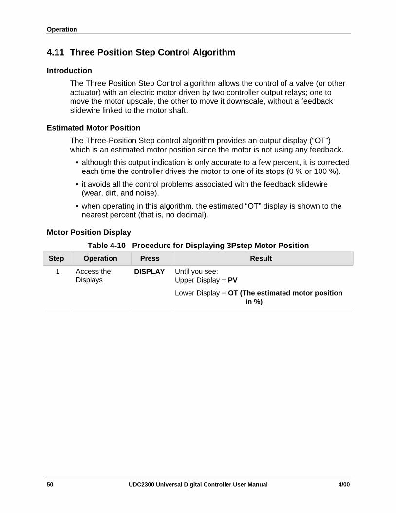
Operation
50 UDC2300 Universal Digital Controller User Manual 4/00
4.11 Three Position Step Control Algorithm
Introduction
The Three Position Step Control algorithm allows the control of a valve (or otheractuator) with an electric motor driven by two controller output relays; one tomove the motor upscale, the other to move it downscale, without a feedbackslidewire linked to the motor shaft.
Estimated Motor Position
The Three-Position Step control algorithm provides an output display (“OT”)which is an estimated motor position since the motor is not using any feedback.
• although this output indication is only accurate to a few percent, it is correctedeach time the controller drives the motor to one of its stops (0 % or 100 %).
• it avoids all the control problems associated with the feedback slidewire(wear, dirt, and noise).
• when operating in this algorithm, the estimated “OT” display is shown to thenearest percent (that is, no decimal).
Motor Position Display
Table 4-10 Procedure for Displaying 3Pstep Motor Position
Step Operation Press Result
1 Access theDisplays
DISPLAY Until you see:Upper Display = PV
Lower Display = OT (The estimated motor positionin %)

Operation
4/00 UDC2300 Universal Digital Controller User Manual 51
4.12 Setting a Failsafe Output Value for Restart After a Power Loss
Introduction
If the power to the controller fails and power is reapplied, the controller goesthrough the power up tests, then goes to a user configured FAILSAFE OUTPUTVALUE.
Set a Failsafe Value
Table 4-11 Procedure for Setting a Failsafe Value
Step Operation Press Result
1 Select ControlSet-up Group
SET UP Until you see:Upper Display = SET
Lower Display = CONTRL
2 Select FailsafeFunctionPrompt
FUNCTION You will see:Upper Display = (range)within the range of the Output 0 to 100 for all outputtypes except 3 Position Step3 Position Step
0 = motor goes to closed position100 = motor goes to open position
Lower Display = FAILSF
3 Select a value [] [] To select a Failsafe output value in the upper display
4 Return toNormal Display
DISPLAY At power up, the output will go to the value set.
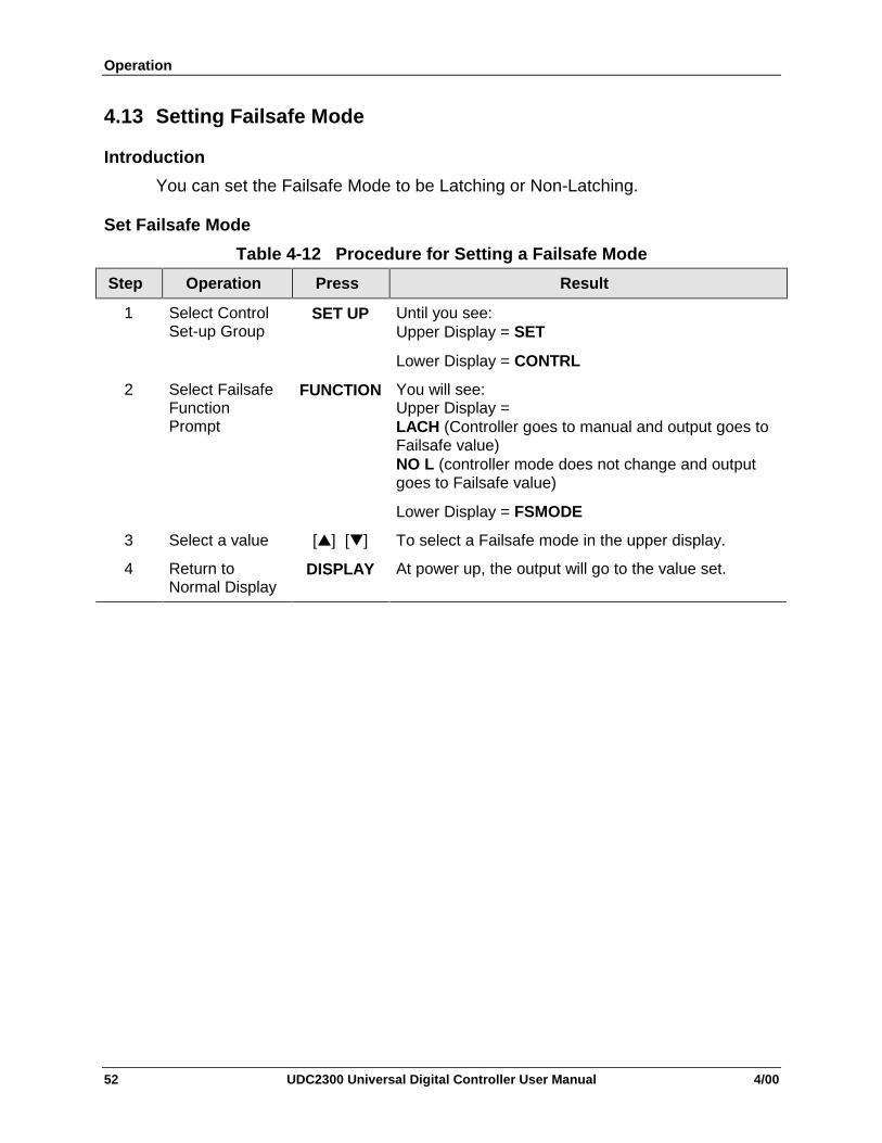
Operation
52 UDC2300 Universal Digital Controller User Manual 4/00
4.13 Setting Failsafe Mode
Introduction
You can set the Failsafe Mode to be Latching or Non-Latching.
Set Failsafe Mode
Table 4-12 Procedure for Setting a Failsafe Mode
Step Operation Press Result
1 Select ControlSet-up Group
SET UP Until you see:Upper Display = SET
Lower Display = CONTRL
2 Select FailsafeFunctionPrompt
FUNCTION You will see:Upper Display =LACH (Controller goes to manual and output goes toFailsafe value)NO L (controller mode does not change and outputgoes to Failsafe value)
Lower Display = FSMODE
3 Select a value [] [] To select a Failsafe mode in the upper display.
4 Return toNormal Display
DISPLAY At power up, the output will go to the value set.

Operation
4/00 UDC2300 Universal Digital Controller User Manual 53
4.14 Entering a Security CodeThe level of keyboard lockout may be changed in the Set Up mode. However,knowledge of a security code number (0 to 4095) may be required to changefrom one level of lockout to another. When a controller leaves the factory, it hasa security code of 0, which permits changing from one lockout level to anotherwithout entering any other code number.
If you require the use of a security code, select a number from 0001 to 4095 andenter it when the lockout level is configured as NONE. Thereafter, that selectednumber must be used to change the lockout level from something other thanNONE.
CAUTION Write the number on the Configuration Record Sheet in Appendix Cso you will have a permanent record.
Table 4-13 Procedure to Enter a Security Code
Step Operation Press Result
1 Enter Set UpMode
SET UP Upper Display = SET UP
Lower Display = TUNING
2 Select any SetUp Group
FUNCTION Upper Display = 0
Lower Display = SECUR
3 Security CodeEntry
[] [] To enter a four digit number in the upper display(0001 to 4095)
This will be your security code.

Operation
54 UDC2300 Universal Digital Controller User Manual 4/00
4.15 Lockout Feature
Introduction
The lockout feature in the UDC2300 is used to inhibit changes (via keyboard) ofcertain functions or parameters by unauthorized personnel.
Lockout levels
There are different levels of Lockout depending on the level of security required.These levels are:
• NONE No Lockout.
• CAL Calibration prompts are locked out.
• CONF Timer, Tuning, SP Ramp, and Accutune are Read/Write. All otherSetup groups are Read only. Calibration Group is not available.
• VIEW Timer, Tuning, and SP Ramp are Read/Write. No otherparameters are available.
• ALL Timer, Tuning, and SP Ramp are Read only. No other parametersare viewable.
Security Code (See previous section)
Individual key lockout
There are four keys that can be disabled to prevent unauthorized changes to theparameters associated with these keys. First set the “Lock” prompt to NONE.
These keys are:
AUTOTUNE Key - you can disable the Autotune key at configuration
Set up, group prompt Tuning”, function prompt “ATUNE”
RUN/HOLD Key - you can disable the Run/Hold key for Set Point
Programming at configuration Set Up group prompt“Tuning,” function prompt “RN HLD”
AUTO/MAN Key - you can disable the Auto/Manual key at configuration
Set Up, group prompt “Tuning”, function prompt“AUTOMA”
FUNCTION Key - you can disable the Set Point Select function key at
configuration Set Up group prompt “Tuning,” functionprompt “SP SEL”
See Subsection3.4 - Tuning Parameters Set Up Group prompts to enable ordisable these keys.

Operation
4/00 UDC2300 Universal Digital Controller User Manual 55
4.16 Background Tests
Introduction
The UDC2300 performs ongoing background tests to verify data and memoryintegrity. If there is a malfunction, an error message will be displayed (blinking)in the lower display.
In the case of simultaneous malfunctions, the messages will appear in sequencein the lower display. Table 4-14 lists these background tests, the reason for theirfailure, and how to correct the problem.
Table 4-14 Background Tests
LowerDisplay
Reason for Failure How to Correct the Problem
E FAIL Unable to write to non-volatilememory. Anytime you change aparameter and it is not accepted, youwill see E FAIL.
1. Check the accuracy of the parameter and re-enter.
2. Try to change something in configuration.
3. Run through Read STATUS tests to re-writeto EEPROM.
FAILSF This error message shows wheneverthe controller goes into a failsafe modeof operation. This will happen if:
• RAM test failed• Configuration test failed• Calibration test failed• Burnout configured for none
and the input failed.
1. Run through STATUS check to determine thereason for the failure.
2. Press the SET UP key until STATUS appearsin the lower display.
3. Press the FUNCTION key to see whether thetests pass or fail, then run through theSTATUS codes a second time to see if theerror cleared.
IN1RNG Input 1 out of range. The process inputis outside the range limits.
1. Make sure the range and actuation areconfigured properly.
2. Check the input source.
3. Restore the factory calibration. (See Section4.17.)
4. Field calibrate.
IN1_FL Two consecutive failures of input 1integration. i.e., cannot make analog todigital conversion. This will happen if:
• Upscale or Downscale burnoutis selected
• Input not configured correctly
1. Make sure the actuation is configuredcorrectly. See Section 4 - Configuration.
2. Make sure the input is correct.
3. Check for gross over-ranging. Check S101jumper position. See Figure 2-1 JumperPlacements
4. Restore factory calibration. See Section 4.17
IN2RNG Input 2 out of range. The remote inputis outside the range limits.
Same as IN1RNG above.
IN2_FL Two consecutive failures of input 2integration. i.e., cannot make analog todigital conversion.
Same as IN1FL above.
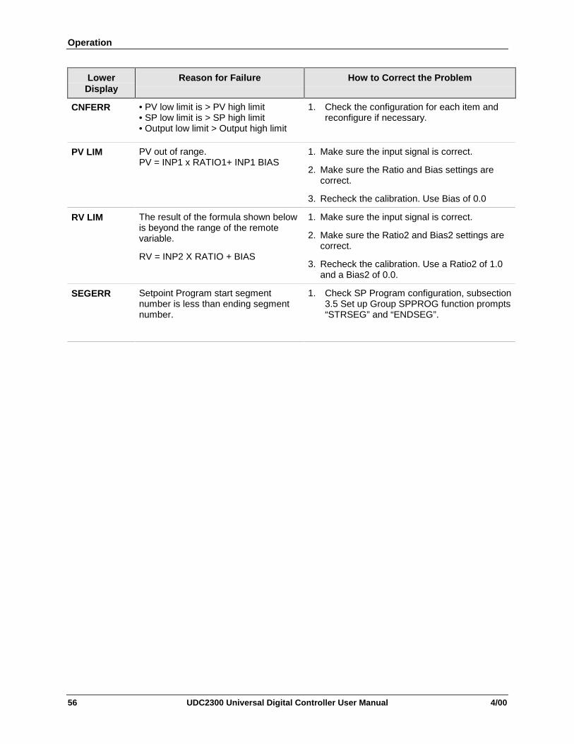
Operation
56 UDC2300 Universal Digital Controller User Manual 4/00
LowerDisplay
Reason for Failure How to Correct the Problem
CNFERR • PV low limit is > PV high limit• SP low limit is > SP high limit• Output low limit > Output high limit
1. Check the configuration for each item andreconfigure if necessary.
PV LIM PV out of range.PV = INP1 x RATIO1+ INP1 BIAS
1. Make sure the input signal is correct.
2. Make sure the Ratio and Bias settings arecorrect.
3. Recheck the calibration. Use Bias of 0.0
RV LIM The result of the formula shown belowis beyond the range of the remotevariable.
RV = INP2 X RATIO + BIAS
1. Make sure the input signal is correct.
2. Make sure the Ratio2 and Bias2 settings arecorrect.
3. Recheck the calibration. Use a Ratio2 of 1.0and a Bias2 of 0.0.
SEGERR Setpoint Program start segmentnumber is less than ending segmentnumber.
1. Check SP Program configuration, subsection3.5 Set up Group SPPROG function prompts“STRSEG” and “ENDSEG”.

Operation
4/00 UDC2300 Universal Digital Controller User Manual 57
4.17 Restore Factory Calibration
Introduction
The factory calibration constants for all the input actuation types that can beused with the controller are stored in its nonvolatile memory. Thus, you canquickly restore the “Factory Calibration” for a given input actuation type by simplychanging the actuation type to another type and then changing it back to theoriginal type. Refer to Table 4-15 for procedure.
ATTENTION: A restored factory calibration overwrites any previous fieldcalibration done for the input and may change the High and Low Range Limits.Be sure to protect any field calibration from accidental overwrites by configuringthe appropriate LOCKOUT selection after calibration.See Section 4.15 for specific instructions to set the lockout.
Table 4-15 Restore Factory Calibration
Step Operation Press Result
1 Set LOCKOUT toNONE
SET UP until you see:Upper Display = SET UPLower Display = TUNING
FUNCTION Until you see:
Upper Display = one of the following:NONE – all parameters are read/writeCAL – all parameters are read/write except CalibrationCONF – configuration parameters are Read Only; no writespermittedVIEW – Tuning and Setpoint Ramp parameters areread/write. No other parameters can be viewed.ALL – Tuning and Setpoint Ramp parameters are availablefor read only. No other parameters can be viewed.Lower Display = LOCK
[] [] Until NONE is in the upper display
2 Enter INPUT 1Setup Group
SET UP until you see:Upper Display = SET UPLower Display = INPUT 1 or 2
FUNCTION until you see:Upper Display = the current selectionLower Display = INxTYP
[] [] to change the current selection to another selection
3 Scroll throughFunctions
FUNCTION until the lower display rolls through the rest of the functions andreturns to:
Upper Display = the new selectionLower Display = INxTYP

Operation
58 UDC2300 Universal Digital Controller User Manual 4/00
Step Operation Press Result
[] [] until you change the input selection in the upper display back tothe proper selection. You will see:
Upper Display = Original Input Selection that matches yourtype of sensor.Lower Display = INxTYP
4 Return to NormalOperation
DISPLAY to return to Normal operating mode.
The factory calibration will be restored. If the problem is notcorrected, contact the Honeywell Technical Assistance Center.
1-800-423-9883 USA and Canada

Setpoint Rate/Ramp/Program Operation
4/00 UDC2300 Universal Digital Controller User Manual 59
5 Setpoint Rate/Ramp/Program Operation
5.1 Setpoint Rate
Introduction
When you have configured a SETPOINT RATE, it will apply immediately to localsetpoint change.
Configuration check
Make sure:
• SPRATE is enabled
• SPRAMP and SPPROG are disabled
• A Rate Up (EUHRUP) or Rate Down (EUHRDN) value has been configuredin Engineering units per hour.
ATTENTION: A value of 0 will imply an immediate change in setpoint, that is,NO RATE applies. See Subsection 3.5 – Configuration group “SPRAMP” fordetails.)
Operation
When a change to local setpoint is made, this controller will ramp from theoriginal setpoint to the “target” setpoint at the rate specified.
The current setpoint value can be viewed at Sn on the lower display.
Power outages
If power is lost before the “target” setpoint is reached, upon power recovery, thecontroller powers up with Sn = Current PV value and it automatically “Restarts”from Sn = current PV value up to the original “target” setpoint.
5.2 Setpoint Ramp
Introduction
When you have configured a SETPOINT RAMP, the ramp will occur between thecurrent local setpoint and a final local setpoint over a time interval of from 1 to255 minutes. You can RUN or HOLD the ramp at any time.
Configuration Check
Make sure
• SPRAMP is enabled

Setpoint Rate/Ramp/Program Operation
60 UDC2300 Universal Digital Controller User Manual 4/00
• SP RATE and SPPROG are disabled
• A Ramp Time (TIMIN) in minutes has been configured
• A final setpoint value (FINLSP) has been configured. See Subsection 3.5 –Configuration group “SPRAMP” for details.
Operation
Running a Setpoint Ramp includes starting, holding, viewing the ramp, endingthe ramp and disabling it. See Table 5-1.
Table 5-1 Running A Setpoint Ramp
Step Operation Press Result
1 SelectAutomatic Mode
MAN/AUTO “A” indicator is on.
Upper Display = Hold and PV valueLower Display = SP and Present value
2 Set StartSetpoint
DISPLAY Until start SP value is in lower display
Upper Display = Hold and PV valueLower Display = SP and start SP value
3 Start the Ramp RUN/HOLD You will seeUpper Display = Run and a changing PV valueLower Display = SP and a changing SP valueincreasing or decreasing toward a final SP value
4 Hold/Run theRamp
RUN/HOLD This holds the ramp at the current setpoint value.Press again to continue.
5 View theremaining ramptime
Until you seeUpper Display = RUN or HOLD and the PV valueLower Display = RP xx HH.MM (time remaining)
6 End the Ramp
DISPLAY
When the final setpoint is reached, “RUN” changesto “HOLD” in the upper display and the controlleroperates at the new final setpoint.
7 DisableSPRAMP
See Section 3.5 – Configuration group “SPRAMP”for details.
Power Outage
If power is lost during a ramp, upon power-up the controller will be in HOLD andthe setpoint value will be the setpoint value prior to the beginning of the setpointramp. The ramp is placed in hold at the beginning.
Configure the mode at Set up Group “CONTROL”, function prompt “PWRUP”.See Section 3.10 – CONTRL GROUP FUNCTION Prompts.

Setpoint Rate/Ramp/Program Operation
4/00 UDC2300 Universal Digital Controller User Manual 61
5.3 Setpoint Ramp/Soak Programming
Introduction
Setpoint Ramp/Soak Programming lets you configure six ramp and six soaksegments to be stored for use as one program or several small programs. Youdesignate the beginning and end segments to determine where the program is tostart and stop.
Review program data and configuration
While the procedure for programming is straightforward, and aided by prompts,we suggest you read “Program Contents”. Table 5-2 lists the program contentsand an explanation of each to aid you in configuration. Then refer to Subsection3.5 – Configuration to enable and configure the setpoint program.
NOTE: SPRATE and SPRAMP must be disabled to enable SP PROG (Set PointProgramming).
Fill out the worksheet
Refer to the example in Figure 5-1and draw a Ramp/Soak Profile on theworksheet provided in Figure 5-2 and fill in the information for each segment.This will give you a record of how the program was developed.
Operation
Refer to Table 5-3 Run/Monitor the program.
Program Contents
Table 5-2 lists all the program contents and a description of each.
Power outage
ATTENTION If power is lost during a program, upon power-up the controller willbe in hold and the setpoint value will be the setpoint value prior to the beginningof the setpoint program. The program is placed in hold at the beginning. Themode will be as configured under “PWR UP” in the “CONTROL” group.

Setpoint Rate/Ramp/Program Operation
62 UDC2300 Universal Digital Controller User Manual 4/00
Table 5-2 Program Contents
Contents DefinitionRamp Segments A ramp segment is the time or rate of change it takes to change the
setpoint to the next setpoint value in the program.• Ramps are odd number segments.• Ramps are configured in either Time or Engineering Units per Minuteor EU per Hour (see Ramp Unit below).
ATTENTION Entering “0” will imply an immediate step change insetpoint to the next soak.
Ramp Unit The Ramp Unit selection determines the engineering units for the rampsegments.The selections are:• TIME = Hours:Minutes (XX:XX) Range: 0-99 hrs: 0-59 min• EU-H = Degrees/Hour OR EU-M = Degrees/Minute (Range – 0-999)
Soak Segments A Soak Segment is a combination of Soak Setpoint (value) and a SoakTime (duration)• Soaks are even number segments.• The Soak Setpoint value must be within the setpoint high and low
range limits in engineering units.• Soak Time is the duration of the soak and is determined in:
TIME - Hours:Minutes Range = 0-99 hrs:59 min.Start Segment The Start Segment number designates the first Ramp segment.
Range = 1 to 11End Segment The End Segment number designates the number of the last Soak
segment. Range = 2 to 12Recycle number The Recycle number allows the program to recycle a specified number
of times from beginning to end. Range = 0 to 99Guaranteed soak All soak segments can have a deviation value of from 0 to ± 99
(specified by SOK DEV) which guarantees that value for that segmenttime.The soak deviation value is the number in engineering units, above orbelow the setpoint, outside of which the timer halts. The range is 0 to± 99.Soak deviation values >0 guarantee that the soak segment’s processvariable is within the ± deviation for the configured soak time. Wheneverthe ± deviation is exceeded, soak timing is frozen.The guaranteed soaks feature is disabled whenever the deviation valueis configured to 0.

Setpoint Rate/Ramp/Program Operation
4/00 UDC2300 Universal Digital Controller User Manual 63
Contents DefinitionPV Start This function determines whether LSP1 or PV is used as the setpoint
when the program is initially changed from HOLD to RUN.
The selections are:
DISABL = When the program is initially changed from HOLD toRUN the present LSP1 value is captured as the default setpoint. If theprogram is terminated or the power cycled before the program hascompleted, the LSP1 is used as the control setpoint. The beginningsegment uses this value as the initial ramp setpoint.
ENABL = When the program is initially changed from HOLD toRUN the present PV value is captured and used as the beginningsetpoint value for the ramp segment. If the program is terminatedbefore completion, the setpoint value will revert back to the PV valuecaptured at the initial HOLD to RUN transition. If the power is cycledbefore program completion, upon power-up the setpoint is set to the PVvalue at power-up and when the program is restarted that setpoint valueis used initially.
Program state The Program State selection determines whether the program is in theHOLD state or Disabled (DIS) after completion of the program.
Programtermination state
The program termination state function determines the status of thecontroller upon completion of the program. The selections are:• LAST = controls to last setpoint• FSAF = manual mode and Failsafe output.
Reset Program toBeginning
When enabled, this selection allows you to reset the program to thebeginning from the keyboard.
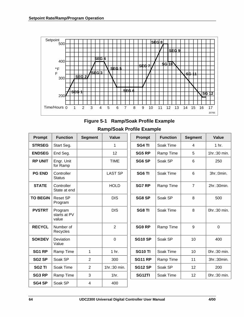
Setpoint Rate/Ramp/Program Operation
64 UDC2300 Universal Digital Controller User Manual 4/00
500
400
200
300
°F
Time/Hours 0 1 2 3 4 5 6 7 8 9 10 11 12 13 14 15 16 17
SEG 2SEG 3
SEG 4
SEG 5
SEG 6
SEG 7
SEG 8
SEG 9
SG 10
SG 11
SG 12SEG 1
F
20765
Setpoint
Figure 5-1 Ramp/Soak Profile Example
Ramp/Soak Profile Example
Prompt Function Segment Value Prompt Function Segment Value
STRSEG Start Seg. 1 SG4 TI Soak Time 4 1 hr.
ENDSEG End Seg. 12 SG5 RP Ramp Time 5 1hr.:30 min.
RP UNIT Engr. Unitfor Ramp
TIME SG6 SP Soak SP 6 250
PG END ControllerStatus
LAST SP SG6 TI Soak Time 6 3hr.:0min.
STATE ControllerState at end
HOLD SG7 RP Ramp Time 7 2hr.:30min.
TO BEGIN Reset SPProgram
DIS SG8 SP Soak SP 8 500
PVSTRT Programstarts at PVvalue
DIS SG8 TI Soak Time 8 0hr.:30 min.
RECYCL Number ofRecycles
2 SG9 RP Ramp Time 9 0
SOKDEV DeviationValue
0 SG10 SP Soak SP 10 400
SG1 RP Ramp Time 1 1 hr. SG10 TI Soak Time 10 0hr.:30 min.
SG2 SP Soak SP 2 300 SG11 RP Ramp Time 11 3hr.:30min.
SG2 TI Soak Time 2 1hr.:30 min. SG12 SP Soak SP 12 200
SG3 RP Ramp Time 3 1hr. SG12TI Soak Time 12 0hr.:30 min.
SG4 SP Soak SP 4 400
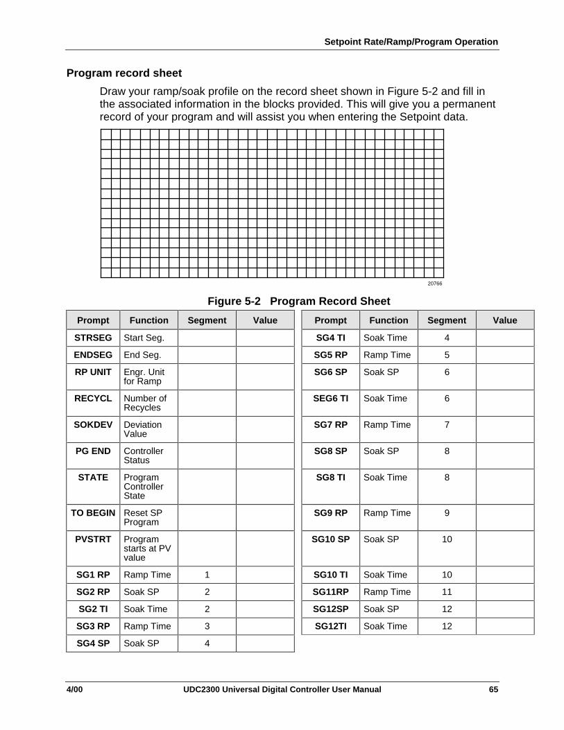
Setpoint Rate/Ramp/Program Operation
4/00 UDC2300 Universal Digital Controller User Manual 65
Program record sheet
Draw your ramp/soak profile on the record sheet shown in Figure 5-2 and fill inthe associated information in the blocks provided. This will give you a permanentrecord of your program and will assist you when entering the Setpoint data.
20766
Figure 5-2 Program Record Sheet
Prompt Function Segment Value Prompt Function Segment Value
STRSEG Start Seg. SG4 TI Soak Time 4
ENDSEG End Seg. SG5 RP Ramp Time 5
RP UNIT Engr. Unitfor Ramp
SG6 SP Soak SP 6
RECYCL Number ofRecycles
SEG6 TI Soak Time 6
SOKDEV DeviationValue
SG7 RP Ramp Time 7
PG END ControllerStatus
SG8 SP Soak SP 8
STATE ProgramControllerState
SG8 TI Soak Time 8
TO BEGIN Reset SPProgram
SG9 RP Ramp Time 9
PVSTRT Programstarts at PVvalue
SG10 SP Soak SP 10
SG1 RP Ramp Time 1 SG10 TI Soak Time 10
SG2 RP Soak SP 2 SG11RP Ramp Time 11
SG2 TI Soak Time 2 SG12SP Soak SP 12
SG3 RP Ramp Time 3 SG12TI Soak Time 12
SG4 SP Soak SP 4

Setpoint Rate/Ramp/Program Operation
66 UDC2300 Universal Digital Controller User Manual 4/00
Run/Monitor functions
Table 5-3 lists all the functions required to run and monitor the program.
Table 5-3 Run/Monitor Functions
Function Press Result
Set the Local Setpoint DISPLAY Upper Display = PV valueLower Display = SP
[] [] To set the Local Setpoint value to where you want theprogram to start out.
Run State RUN/HOLD Initiates the setpoint program.
“RUN” appears in the upper display indicating that theprogram is running.
Hold State RUN/HOLD Holds the setpoint program.“HOLD” appears in the upper display indicating thatthe program is in the HOLD state.The setpoint holds at the current setpoint.
External Hold If Remote Switching (Digital Input Option) is presenton your controller, contact closure places the controllerin the HOLD state, if the setpoint program is running.The “HOLD” in the upper display will be displayedperiodically in lower case.
ATTENTION The keyboard takes priority over theexternal switch for the RUN/HOLD function.
Contact reopening runs program.
Viewing the presentramp or soak segmentnumber and time
DISPLAYuntil you
see
Upper Display = PV valueLower Display = XXHH.MM
Time remaining in the SEGMENT in hours andminutes. XX = 1 to 12
Viewing the number ofcycles left in theprogram
DISPLAYuntil you
see
Upper Display = PV valueLower Display = REC_XX
Number of cycles remaining in the setpoint program.X = 0 to 99
End Program When the final segment is completed, the “RUN” in theupper display either changes to “HOLD” (if configuredfor HOLD state), or disappears (if configured fordisable of setpoint programming).
The controller either operates at the last setpoint in theprogram or goes into manual mode/Failsafe output.
Disable Program See Section 3.5 – Configuration Group “SPPROG” fordetails.

Environmental and Operating Conditions
4/00 UDC2300 Universal Digital Controller User Manual 67
6 Appendix A - Environmental and Operating Conditions
Operating Limits Ambient Temperature: 32 °F to 131 °F (0 °C to 55 °C)
Relative Humidity: 5 % to 90 % RH up to 104 °F (40 °C)
Vibration:Frequency: 0 to 200 HzAcceleration: 0.6g
Mechanical Shock:Acceleration: 5gDuration: 30 ms
Power:90 Vac to 264 Vac, 50/60 Hz(CSA models rated to 250 Vac maximum)
Power Consumption: 12 VA maximum
Accuracy ± 0.25 % of span typical± 1 digit for display15-bit resolution typical
CE Conformity SpecialConditions (Europe)
Shielded twisted-pair cables are required for all analogI/O, process variable, RTD, thermocouple, dc Millivolts,low level signal, 4-20 mA, digital I/O, and computerinterface circuits.
Refer to 51-52-05-01, How to Apply DigitalInstrumentation in Severe Electrical Noise Environments,for additional information.

Environmental and Operating Conditions
68 UDC2300 Universal Digital Controller User Manual 4/00
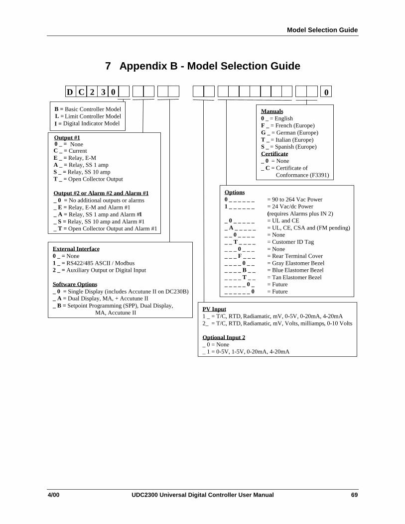
Model Selection Guide
4/00 UDC2300 Universal Digital Controller User Manual 69
7 Appendix B - Model Selection Guide
0D C 2 3 0
External Interface0 _ = None1 _ = RS422/485 ASCII / Modbus2 _ = Auxiliary Output or Digital Input
Software Options_ 0 = Single Display (includes Accutune II on DC230B)_ A = Dual Display, MA, + Accutune II_ B = Setpoint Programming (SPP), Dual Display,
MA, Accutune II
Manuals0 _ = EnglishF _ = French (Europe)G _ = German (Europe)T _ = Italian (Europe)S _ = Spanish (Europe)Certificate_ 0 = None_ C = Certificate of Conformance (F3391)
Options0 _ _ _ _ _ _ = 90 to 264 Vac Power1 _ _ _ _ _ _ = 24 Vac/dc Power
(requires Alarms plus IN 2)_ 0 _ _ _ _ _ = UL and CE_ A _ _ _ _ _ = UL, CE, CSA and (FM pending)_ _ 0 _ _ _ _ = None_ _ T _ _ _ _ = Customer ID Tag_ _ _ 0 _ _ _ = None_ _ _ F _ _ _ = Rear Terminal Cover_ _ _ _ 0 _ _ = Gray Elastomer Bezel_ _ _ _ B _ _ = Blue Elastomer Bezel_ _ _ _ T _ _ = Tan Elastomer Bezel_ _ _ _ _ 0 _ = Future_ _ _ _ _ _ 0 = Future
B = Basic Controller ModelL = Limit Controller ModelI = Digital Indicator Model
Output #1
C _ = CurrentE _ = Relay, E-MA _ = Relay, SS 1 ampS _ = Relay, SS 10 ampT _ = Open Collector Output
Output #2 or Alarm #2 and Alarm #1_ 0 = No additional outputs or alarms_ E = Relay, E-M and Alarm #1_ A = Relay, SS 1 amp and Alarm #1_ S = Relay, SS 10 amp and Alarm #1_ T = Open Collector Output and Alarm #1
PV Input1 _ = T/C, RTD, Radiamatic, mV, 0-5V, 0-20mA, 4-20mA2_ = T/C, RTD, Radiamatic, mV, Volts, milliamps, 0-10 Volts
Optional Input 2_ 0 = None_ 1 = 0-5V, 1-5V, 0-20mA, 4-20mA
None 0 _ =
Model Selection Guide
70 UDC2300 Universal Digital Controller User Manual 4/00

Configuration Record Sheet
4/00 UDC2300 Universal Digital Controller User Manual 71
8 Appendix C - Configuration Record Sheet
Enter the value or selection for each prompt on this sheet so you will have arecord of how your controller was configured.
GroupPrompt Function Prompt
Value orSelection
FactorySetting
GroupPrompt
FunctionPrompt
Value orSelection
FactorySetting
TIMER TIMERPERIODSTARTL DISPRESETINCRMT
__________________________________________
DIS0:01KEYTREMKEYMIN
ATUNE FUZZYTUNEAT ERR
_____________________
DISTUNE---
TUNING PB or GAINRATE TI MIN or I RPM MANRSTPB2 or GAIN 2RATE2TI2 MIN or I2 RPMCYCT1 or CT1X3CYC2T2 or CT2X3SECURLOCKAUTOMAA TUNERN HLDSP SEL
_______________________________________________________________________________________________________________________
1.00.001.01.00.00.001.0202020200CALENABENABENABENAB
ALGOR CTRALGOUTALG4-20RGRLY TY
____________________________
PIDA(MOXL)100127
SPRAMP SPRAMPATI MINFINLSPSPRATEEUHRUPEUHRDNSPPROG
_________________________________________________
DIS31000DIS00DIS
INPUT1 DECIMALUNITSIN1TYPXMITR1IN1 HIIN1 LORATIO1BIAS 1RILTR1BRNOUTEMISFREQDISPLYLNGUAG
__________________________________________________________________________________________________
8888DegFKHLIN240001.000.01.0UP1.060SPENGL
Configuration Record Sheet continued on next page

Configuration Record Sheet
72 UDC2300 Universal Digital Controller User Manual 4/00
GroupPrompt Function Prompt
Value orSelection
FactorySetting
GroupPrompt
FunctionPrompt
Value orSelection
FactorySetting
INPUT2 IN2TYPLININ2 HIIN2 LORATIO2BIAS 2FILTR2
_________________________________________________
1-5VLIN240001.000.01.0
COM ComSTAComADRSDENABSHDTIMPARITYBAUDWS_FLTTX_DLYSDMODESHDSPUNITSCSRATOCSP_BILOOPBACK
__________________________________________________________________________________________________
Disable0Enable0Odd9600FP_B1LastLSPPCT1.00Disable
CONTRL PIDSETSW VALLSP’SRSPSRCSP TRKPWR UPPWROUTSP HiSP LoACTIONOUT HiOUT LoD BANDHYSTFAILSFFSMODEPBorGNMINRPM
______________________________________________________________________________________________________________________________
ONE0.00ONENONENONEMANLAST24000REV10002.00.50.0NOLGAINMIN
ALARMS A1S1VAA1S2VAA2S1VAA2S2VAA1S1TYA1S1TYA2S1TYA2S2TYA1S1HLA1S1EVA1S2HLA1S2EVA2S1HLA2S1EVA2S2HLA2S2EVALHYSTALARM1BLOCK
_____________________________________________________________________________________________________________________________________
90909090NONENONENONENONEHIGHBEGNHIGHBEGNHIGHBEGNHIGHBEGN0.0NOLDIS
OPTIONS AUXOUT0 PCT100 PCTDIG INDIG COM
___________________________________
DIS0100NONEDIS


Sensing and ControlHoneywell11 West Spring StreetFreeport, IL 61032
51-52-25-83D 0400 Printed in USA www.honeywell.com/sensing