ucop seismic performance level - capital strategies...seismic base shear, v (kips): 80,965 kips...
TRANSCRIPT

Evaluator: XXX Evaluator: EGM/BLDate: 03/06/2019
Page 1
07-15-19
ASCE 41-17 Tier 1 Seismic Evaluation Building Name: David Gardner Stacks WestCAAN ID: 1297Auxiliary Building ID: NoneAddress: Core Campus, Berkeley, 94720Site location coordinates: Latitude 37.872523 o Longitudinal -122.259640 o
Plan Roof (Looking West)
UCOP SEISMIC PERFORMANCE LEVEL (OR “RATING”) BASED ON TIER 1 EVALUATION FINDINGS: IV
BUILDING DATAASCE 41-17 Model Building Type (Governing Building Type bolded for Seismic Risk Model when multiple types exist):
a. Longitudinal Direction: C2: Concrete Shear Walls (with Stiff Diaphragm)b. Transverse Direction: C2: Concrete Shear Walls (with Stiff Diaphragm)
Square Footage: 79,515 sq. ft. out of 189,425 (UCB Records)Building Length: 289’-0” (E-W direction)Building Width: 117’-0” (N-S direction)Building Height: Varies, 25’-3” minimum and 40’-1” maximumStory Height: 13’-8” (Level D at the base – Level C), 12’-0” (Level C- Level B mezzanine), 11’-7” minimum (Level C – Roof at low point ) and 26’-5” maximum (Level C-Roof at high point at Doe Terrace). Number of stories above grade: NoneNumber of basement stories below grade: 2
Year of Original Construction and Code Year: Construction was completed in 1994 and the drawings are dated 1992 and reference the 1988 UBC.
Year of Later Constuction and Code Year: No retrofits, additions, or alterations
COST RANGE TO RETROFIT (if applicable): Not applicable

Building Name: D. Gardner Stacks West Evaluator: EGM/BLCAAN ID: 1297 Date: 03/06/2019
Page 2
BUILDING DESCRIPTIONGeneralDavid Gardner Stacks West is a two-story below grade structure located on the Core UC Berkeley Campus. It is situated to the north of the Doe Library and to the east of the Moffitt Library. David Gardner Stacks West is located partially below the patio terrace which forms the main entry to the Doe Library and partially below the green space know as Memorial Glade. The roof of David Gardner Stacks West slopes upward from west to east to follow the grade of Memorial Glades.
Construction was completed in 1994, and it is a reinforced concrete building with a rectangular footprint measuring approximately 289’-0” east-west by 117’-0” north-south. It contains a 13’-8” tall lower story and an upper story which varies in height from 11’-7” at the low point to 26’-5” at the high point. A mezzanine is situated in the taller portion of the upper story in the southeast portion of the building. The building is connected to the Moffitt Library and to Gardner Stacks East below grade. The structure functions as a library and contains the majority of the book collection that was formerly housed in the Doe Library. It also provides independent study and collaboration areas for the University students.
Structural SystemThe gravity load-carrying system is comprised of a 26”, 22”, or 21” deep reinforced concrete waffle slab that spans to reinforced concrete columns. The slab is either 5” or 6” thick and is situated over 16” or 20” deep by 6” wide reinforced concrete beams. The beams are typically spaced at 2’-6” o.c. in each direction. Reinforced concrete columns are spaced in 26’-0” by 26’-0” bays and are 24” square. They are reinforced vertically with 8-#8 bars as a minimum up to 16-#11 bars as a maximum. They contain either 3 or 4 legs of closed #4 ties spaced at 12” o.c.
The lateral load-resisting system consists of reinforced concrete shear walls in both the transverse and longitudinal direction. In the longitudinal (east-west) direction, exterior shear walls also serve as soil retaining walls. On each face, these walls contain #7 or #8 bars spaced at 9” o.c. in the vertical direction and #4 bars spaced at 12”o.c. in the horizontal direction. There are 8 shear walls oriented in the transverse (north-south) direction. One wall is located on the west elevation and the remaining 7 walls are located in the building interior. The interior walls are reinforced with #4 bars spaced at 12”o.c. on each face in each way. Concrete columns located at the ends of transverse shear walls or below discontinuous walls are designated as “ductile” and contain #4 ties spaced at 3 ½” o.c.
Square reinforced concrete footings are located below columns. These range in size from 5’-6” square by 2’-0” thick to 9’-0” square by 3’-6” thick. Continuous wall footings are typically 4’-0” wide and 2’-6” thick. The exterior face of the walls aligns with the exterior face of the wall footings.
Building Condition: Good
Date of Site Visit: 02/08/2019, Bret Lizundia, Rutherford + ChekeneLimitations of walk-through: Not all rooms were entered
SITE INFORMATIONSite Class (A-F): B Basis: Site Specific Zone Map of campus by Geomatrix
Building Name: D. Gardner Stacks West Evaluator: EGM/BLCAAN ID: 1297 Date: 03/06/2019
Page 3
Site Specific Ground Motion Study? Yes, 2015 Update to the Site-Specific Seismic Hazard Analyses and Development of Seismic Design Ground MotionsBSE-1N Spectral Accelerations: Basis: 2015 Update to the Site-Specific Seismic Hazard Analyses and Development of Seismic Design Ground Motions, Table 5 for Soil < 10 ft based on depth of rock readings from Site Specific Zone Map of campus by Geomatrix and the information in Preliminary Geotechnical Investigation Main Library Planning Study UC Berkeley, Rutherford + Chekene, December 23, 1986SDS: 1.71 SD1: 0.61BSE-2E Spectral Accelerations: Basis: 2015 Update to the Site-Specific Seismic Hazard Analyses and Development of Seismic Design Ground Motions, Table 6 for Soil < 10ft based on depth of rock readings from Site Specific Zone Map of campus by Geomatrix and the information in Preliminary Geotechnical Investigation Main Library Planning Study UC Berkeley, Rutherford + Chekene, December 23, 1986SXS: 2.31 SX1: 0.85Level of Seismicity: HighPerformance Level: Collapse Prevention Structural Performance
Geologic Hazards: Fault Rupture: No Basis: CGS website http://maps.conservation.ca.gov/cgs/informationwarehouse/Liquefaction: No Basis: CGS website http://maps.conservation.ca.gov/cgs/informationwarehouse/Landslide: No Basis: CGS website http://maps.conservation.ca.gov/cgs/informationwarehouse/
PREVIOUS RATINGS SUMMARYNone to date
DOCUMENTATIONArchitectural Drawings: Doe/Moffitt Libraries Addition and Seismic Improvements: North Addition, Esherick Homsey Dodge and Davis, 31 January 1992, A1.1, 1-A2.1 to 1-A2.9, 1-A3.1 to , 1-A3.6, 1-A4.1 to 1-A4.7, 1-A5.1 to 1-A5.7, 1-A6.1 to 1-A6.4, 1-A7.1, 1-A7.3 to 1-A7.4, 1-A8.1 to 1-A8.7, 1-A9.1, 1-A9.3, 1-A10.1 to 1-A10.6, 1-A11.1 to 1-A11.8, 1-A11.10, 1-A11.11, 1-A12.1 to 1-A12.6, 1-A12.8 to 1-A12.10Structural Drawings: Doe/Moffitt Libraries Addition and Seismic Improvements: North Addition, Rutherford + Chekene, 31 January 1992,1-S0.1, 1-S2.1 to 1-S2.9, 1-S3.1, 1-S4.1 to 1-S4.11, 1-S5.2 to 1-S5.10, 1-S6.1, 1-S7.1 to 1-S7.3Seismic Evaluations: NoneGeotechnical Reports: Preliminary Geotechnical Investigation Main Library Planning Study UC Berkeley, Rutherford + Chekene, December 23, 1986Other Documents: None
CONSTRUCTION DATA
Gravity Load Structural System: Reinforced concrete waffle slab spanning to reinforced concrete columns
Exterior Transverse Walls: Reinforced concrete shear walls
Opening(s)? No
Exterior Longitudinal Walls: Reinforced concrete shear walls
Opening(s)? No

Building Name: D. Gardner Stacks West Evaluator: EGM/BLCAAN ID: 1297 Date: 03/06/2019
Page 4
LATERAL-FORCE-RESISTING SYSTEM
Longitudinal TransverseASCE 41-17 Building Type: C2: conc. shear wall C2: conc. shear wall
Diaphragms: 5” or 6” conc. slab 5” or 6” conc. slabVertical Elements: 24” sq. conc. gravity
columns and 12” thick concrete shear walls
24” sq. conc. gravity columns and 12” thick concrete shear walls
Connections: Conc. beams cast on either side of walls. Vertical wall reinf. runs through beams and horiz. slab reinf. runs through wall. Beam longitudinal bars are tied with closely spaced ties that also pass thru the walls.
Conc. beams cast on either side of walls. Vertical wall reinf. runs through beams and horiz. slab reinf. runs through wall. Beam longitudinal bars are tied with closely spaced ties that also pass thru the walls.
Details: 1-S5.6 for connections 1-S5.6 for connectionsEstimated Fundamental Period, T (sec): 0.31 sec 0.31 sec
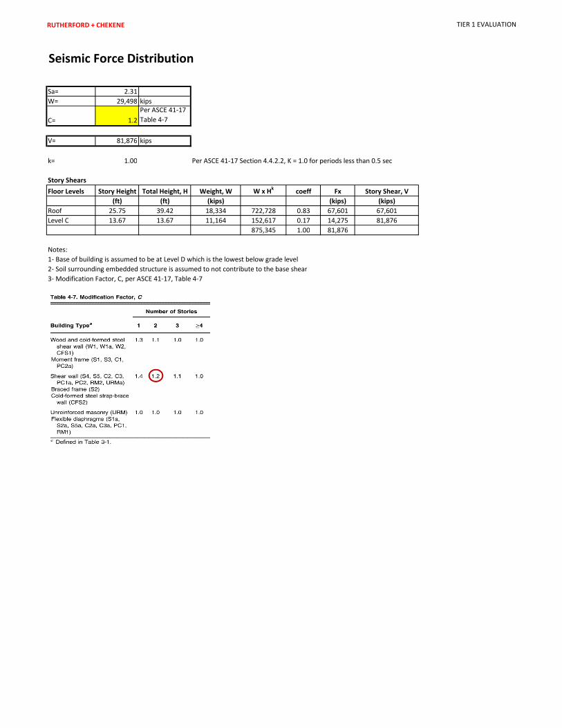
BSE-2E Spectral Acceleration, Sa: 2.31g 2.31gModification Factor, C: 1.2 (C2 – Table 4-7) 1.2 (C2 – Table 4-7)
Building Weight, W (kips): 29,170 kips 29,170 kipsSeismic Base Shear, V (kips): 80,965 kips 80,965 kips
System Modification Factor, Ms: 4.5 4.5
Roof Materials/Framing: 6” topping slab over load-bearing EPS foam over waffle structural slab
Intermediate Floors/Framing: Typical floor is 5” slab spanning to 6” wide by 16” deep beams spaced at 2’-6” o.c.
Ground Floor: 5” concrete slab-on-grade over membrane over 3” concrete mud slab over 12” gravel
Columns: 24” square reinforced concrete columns
Foundation: Spread footings under the columns, strip footings under the walls
General Condition of Structure: GoodEvidence of Settling?: No
Special Features & Comments:
Building Name: D. Gardner Stacks West Evaluator: EGM/BLCAAN ID: 1297 Date: 03/06/2019
Page 5
Significant Structural Deficiencies, Potentially Affecting Seismic Performance Level Designation:
Lateral System Stress Check (wall shear, column shear or flexure, or brace axial as applicable)☐ Load Path Adjacent Buildings☐ Weak Story ☐ Soft Story ☐ Geometry (vertical irregularities)☐ Torsion☐ Mass – Vertical Irregularity☐ Cripple Walls☐ Wood Sills (bolting)☐ Diaphragm Continuity☐ Openings at Shear Walls (concrete or masonry)☐ Liquefaction☐ Slope Failure☐ Surface Fault Rupture☐ Masonry or Concrete Wall Anchorage at Flexible Diaphragm☐ URM wall height to thickness ratio☐ URM Parapets or Cornices☐ URM Chimney☐ Heavy Partitions Braced by Ceilings☐ Appendages
OVERALL SEISMIC DEFICIENCIES & EXPECTED SEISMIC PERFORMANCEDavid Gardner Stacks West is a 2-story below grade reinforced concrete structure that is rectangular in plan. The exterior walls retain soil on the north, south, and west elevation. On the interior, shear walls are spaced approximately every 78 ft. Columns with ductile tie detailing, having ties spaced at 3.5” o.c., are located at the ends of short interior shear walls as well as below any discontinuous walls. This structure contains a mezzanine level that is laterally connected to multiple interior shear walls in the transverse direction and to one wall along its length in the longitudinal direction. For the purpose of the Tier 1 analysis, Gardner Stacks West is assumed to be an above grade structure with its seismic base set to Level D and soil-structure interaction is ignored. This structure does not contain any significant structural irregularities or nonstructural components that pose risk.
The Tier 1 quick checks indicate a number of deficiencies, including an undersized seismic joint, shear critical columns, and overstressed shear walls.
The seismic gap between David Gardner West and the adjacent Moffitt Library and David Gardner East is 4” wide. The Tier 1 Basic checklist for collapse prevention requires a joint that is 1.5% of the building height which would be approximately 7”. David Gardner West and the adjacent structures contain concrete shear walls as the lateral load-resisting system. It is likely that the 4” gap is adequate given the stiffness of this system.
Building Name: D. Gardner Stacks West Evaluator: EGM/BLCAAN ID: 1297 Date: 03/06/2019
Page 6
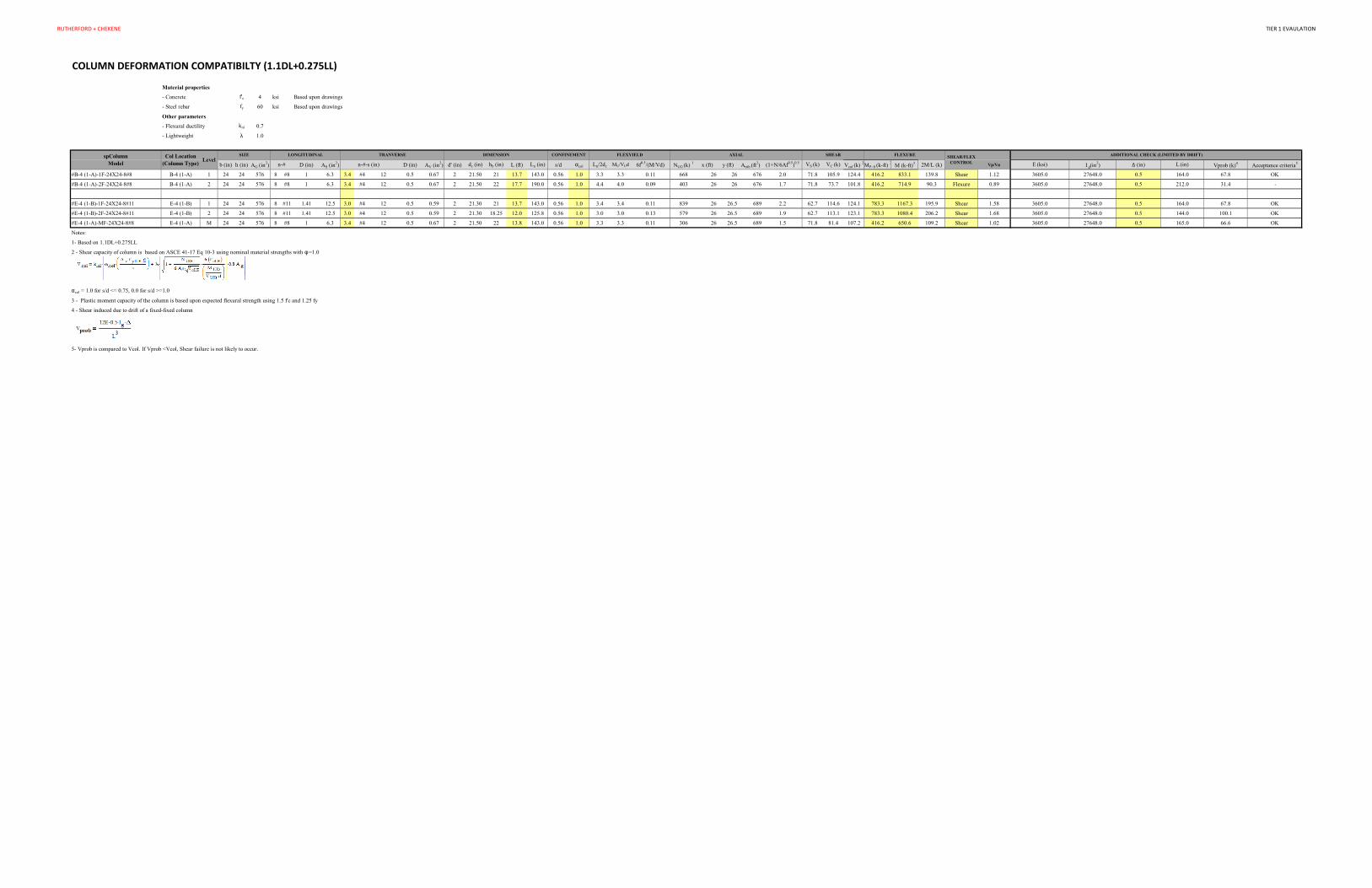
Many gravity columns in David Gardner Stacks East are shear critical. However, they have sufficient shear capacity to resist the shear forces induced by a conservative ½” estimate for interstory drift.
Finally, the Tier 1 checklists indicate the average shear stress in the walls exceeds the allowable limit at BSE-2E. The stresses in the walls on the 1st and 2nd stories are 301 psi and 190 psi respectively. These are in excess of the 126 psi limit specified in Tier 1. The shear walls were subsequently checked using ASCE 7-10 and are sufficient.
Seismic Performance Level Rating A Seismic Performance Level of IV is assigned to David Gardner Stacks West Hall based on the Tier 1 evaluation. Due to the Tier 1 deficiencies described above including an undersized seismic joint, shear critical columns, and overstressed shear walls, this building would be assigned a Rating of V. However, UC Berkeley allows the rating to be upgraded by one level through a peer review process if there is sufficient justification. A peer review of David Gardner Stacks West took place on February 28, 2019 with the Bay Area structural engineering firms Rutherford + Chekene, Degenkolb Engineers, and Forell/Elsesser Engineers present. The group reached a consensus that David Gardner West will receive a Rating of IV due to mitigating circumstances that occur in the structure. This building is below grade, and the Tier 1 assessment conservatively ignored soil-structure interaction by analyzing the building as if it were above grade. In addition, the walls are adequate when checked using ASCE 7-10 for new building design. Finally, given the stiffness of the lateral shear walls, the building drift is likely to be minimal which is ignored by the Tier 1 calculations. As a result, the column deformation compatibility and seismic joint are likely to be adequate.
Recommended Next StepEven though no further analysis is required, it is recommended that an ASCE 41 Tier 2 analysis be performed for the structure to determine the adequacy of the seismic joint, and the shear walls.
Seismic Retrofit Concept Sketches/Description (only if above-listed rating is V or greater): Seismic retrofit is not required.
Appendices
A. Additional Images
B. ASCE 41-17 Tier 1 Checklists (Structural)
C. UCOP Seismic Safety Policy Falling Hazards Assessment Summary
D. Quick Check Calculations
APPENDIX A
Additional Images

Building Name: D. Gardner Stacks West Evaluator: R+C
CAAN ID: 1297 Date: 03/06/19
Page 2
Plan

Building Name: D. Gardner Stacks West Evaluator: R+C
CAAN ID: 1297 Date: 03/06/19
Page 3
Terrace Roof and Memorial Glade (Looking West)
Seismic Joint

Building Name: D. Gardner Stacks West Evaluator: R+C
CAAN ID: 1297 Date: 03/06/19
Page 4
Interior Stacks (looking west with mezzanine on left)
Compact Shelving

APPENDIX B
ASCE 41-17 Tier 1 Checklists (Structural)
UC Campus: Berkeley Date: 3/06/2019
Building CAAN: 1297 Auxiliary CAAN:
By Firm: Berkeley
Building Name: David Gardner Stacks West Initials: EGM Checked: BL
Building Address: Core Campus, Berkeley, 94720 Page: 1 of 3
ASCE 41-17
Collapse Prevention Basic Configuration Checklist
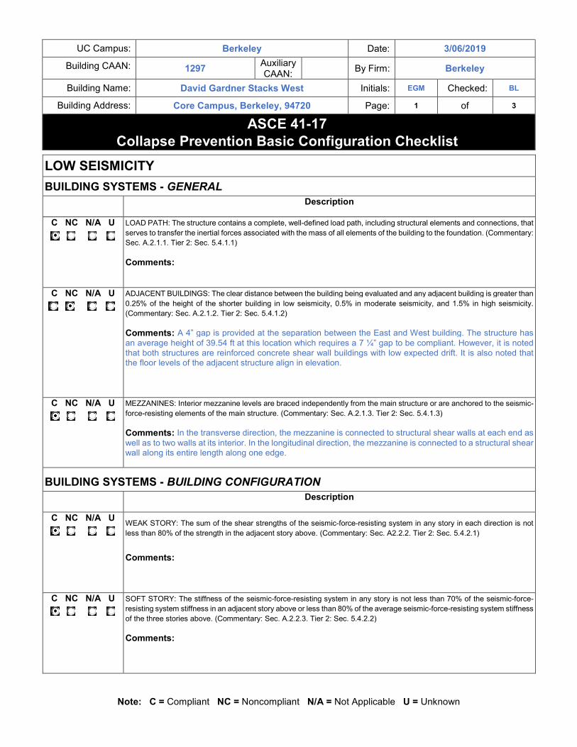
Note: C = Compliant NC = Noncompliant N/A = Not Applicable U = Unknown
LOW SEISMICITY
BUILDING SYSTEMS - GENERAL
Description
C NC N/A U
LOAD PATH: The structure contains a complete, well-defined load path, including structural elements and connections, that
serves to transfer the inertial forces associated with the mass of all elements of the building to the foundation. (Commentary:
Sec. A.2.1.1. Tier 2: Sec. 5.4.1.1)
Comments:
C NC N/A U
ADJACENT BUILDINGS: The clear distance between the building being evaluated and any adjacent building is greater than
0.25% of the height of the shorter building in low seismicity, 0.5% in moderate seismicity, and 1.5% in high seismicity.
(Commentary: Sec. A.2.1.2. Tier 2: Sec. 5.4.1.2)
Comments: A 4” gap is provided at the separation between the East and West building. The structure has
an average height of 39.54 ft at this location which requires a 7 ¼” gap to be compliant. However, it is noted
that both structures are reinforced concrete shear wall buildings with low expected drift. It is also noted that the floor levels of the adjacent structure align in elevation.
C NC N/A U
MEZZANINES: Interior mezzanine levels are braced independently from the main structure or are anchored to the seismic-
force-resisting elements of the main structure. (Commentary: Sec. A.2.1.3. Tier 2: Sec. 5.4.1.3)
Comments: In the transverse direction, the mezzanine is connected to structural shear walls at each end as
well as to two walls at its interior. In the longitudinal direction, the mezzanine is connected to a structural shear wall along its entire length along one edge.
BUILDING SYSTEMS - BUILDING CONFIGURATION
Description
C NC N/A U
WEAK STORY: The sum of the shear strengths of the seismic-force-resisting system in any story in each direction is not
less than 80% of the strength in the adjacent story above. (Commentary: Sec. A2.2.2. Tier 2: Sec. 5.4.2.1)
Comments:
C NC N/A U
SOFT STORY: The stiffness of the seismic-force-resisting system in any story is not less than 70% of the seismic-force-
resisting system stiffness in an adjacent story above or less than 80% of the average seismic-force-resisting system stiffness
of the three stories above. (Commentary: Sec. A.2.2.3. Tier 2: Sec. 5.4.2.2)
Comments:

UC Campus: Berkeley Date: 3/06/2019
Building CAAN: 1297 Auxiliary CAAN:
By Firm: Berkeley
Building Name: David Gardner Stacks West Initials: EGM Checked: BL
Building Address: Core Campus, Berkeley, 94720 Page: 2 of 3
ASCE 41-17
Collapse Prevention Basic Configuration Checklist
Note: C = Compliant NC = Noncompliant N/A = Not Applicable U = Unknown
C NC N/A U
VERTICAL IRREGULARITIES: All vertical elements in the seismic-force-resisting system are continuous to the foundation.
(Commentary: Sec. A.2.2.4. Tier 2: Sec. 5.4.2.3)
Comments: No walls that form part of the primary lateral force resisting system are discontinuous. However,
one wall located between the Mezzanine – Roof on Grid 3.3/D-FO.5 was added to support the upper roof and is discontinuous. The columns supporting this wall contain ductile ties spaced at 3 ½” o.c.
C NC N/A U
GEOMETRY: There are no changes in the net horizontal dimension of the seismic-force-resisting system of more than 30%
in a story relative to adjacent stories, excluding one-story penthouses and mezzanines. (Commentary: Sec. A.2.2.5. Tier 2:
Sec. 5.4.2.4)
Comments:
C NC N/A U
MASS: There is no change in effective mass of more than 50% from one story to the next. Light roofs, penthouses, and
mezzanines need not be considered. (Commentary: Sec. A.2.2.6. Tier 2: Sec. 5.4.2.5)
Comments:
C NC N/A U
TORSION: The estimated distance between the story center of mass and the story center of rigidity is less than 20% of
the building width in either plan dimension. (Commentary: Sec. A.2.2.7. Tier 2: Sec. 5.4.2.6)
Comments:
MODERATE SEISMICITY (COMPLETE THE FOLLOWING ITEMS IN ADDITION TO THE ITEMS FOR LOW SEISMICITY)
GEOLOGIC SITE HAZARD
Description
C NC N/A U
LIQUEFACTION: Liquefaction-susceptible, saturated, loose granular soils that could jeopardize the building’s seismic
performance do not exist in the foundation soils at depths within 50 ft (15.2m) under the building. (Commentary: Sec. A.6.1.1.
Tier 2: 5.4.3.1)
Comments:
C NC N/A U
SLOPE FAILURE: The building site is located away from potential earthquake-induced slope failures or rockfalls so that it is unaffected by such failures or is capable of accommodating any predicted movements without failure. (Commentary: Sec. A.6.1.2. Tier 2: 5.4.3.1)
Comments:

UC Campus: Berkeley Date: 3/06/2019
Building CAAN: 1297 Auxiliary CAAN:
By Firm: Berkeley
Building Name: David Gardner Stacks West Initials: EGM Checked: BL
Building Address: Core Campus, Berkeley, 94720 Page: 3 of 3
ASCE 41-17
Collapse Prevention Basic Configuration Checklist
Note: C = Compliant NC = Noncompliant N/A = Not Applicable U = Unknown
MODERATE SEISMICITY (COMPLETE THE FOLLOWING ITEMS IN ADDITION TO THE ITEMS FOR LOW SEISMICITY)
GEOLOGIC SITE HAZARD
C NC N/A U
SURFACE FAULT RUPTURE: Surface fault rupture and surface displacement at the building site are not anticipated.
(Commentary: Sec. A.6.1.3. Tier 2: 5.4.3.1)
Comments:
HIGH SEISMICITY (COMPLETE THE FOLLOWING ITEMS IN ADDITION TO THE ITEMS FOR MODERATE SEISMICITY)
FOUNDATION CONFIGURATION
Description
C NC N/A U
OVERTURNING: The ratio of the least horizontal dimension of the seismic-force-resisting system at the foundation level to the building height (base/height) is greater than 0.6Sa. (Commentary: Sec. A.6.2.1. Tier 2: Sec. 5.4.3.3)
Comments: On Grid 9 B= 26 ft, H=32 ft, B/H = 0.81
Sa = 2.31 for UCB at BSE 2 0.6x Sa = 1.39
B/H < 0.6 Sa
Note that the calculation above is for the shortest wall in the structure. The likelihood of overturning for an embedded building with this aspect ratio is negligible.
C NC N/A U
TIES BETWEEN FOUNDATION ELEMENTS: The foundation has ties adequate to resist seismic forces where footings, piles, and piers are not restrained by beams, slabs, or soils classified as Site Class A, B, or C. (Commentary: Sec. A.6.2.2. Tier 2: Sec. 5.4.3.4)
Comments: Soil Site Class B
UC Campus: Berkeley Date: 3/06/2019
Building CAAN: 1297 Auxiliary CAAN:
By Firm: Berkeley
Building Name: David Gardner Stacks West Initials: EGM Checked: BL
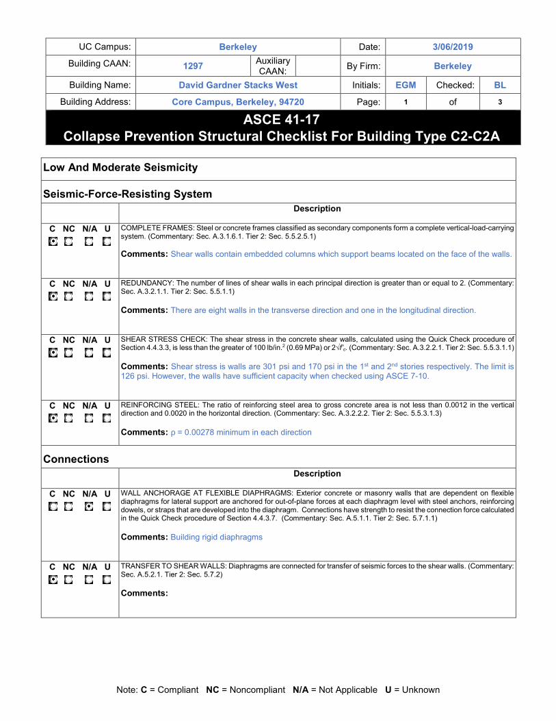
Building Address: Core Campus, Berkeley, 94720 Page: 1 of 3
ASCE 41-17
Collapse Prevention Structural Checklist For Building Type C2-C2A
Note: C = Compliant NC = Noncompliant N/A = Not Applicable U = Unknown
Low And Moderate Seismicity
Seismic-Force-Resisting System
Description
C NC N/A U
COMPLETE FRAMES: Steel or concrete frames classified as secondary components form a complete vertical-load-carrying system. (Commentary: Sec. A.3.1.6.1. Tier 2: Sec. 5.5.2.5.1) Comments: Shear walls contain embedded columns which support beams located on the face of the walls.
C NC N/A U
REDUNDANCY: The number of lines of shear walls in each principal direction is greater than or equal to 2. (Commentary: Sec. A.3.2.1.1. Tier 2: Sec. 5.5.1.1)
Comments: There are eight walls in the transverse direction and one in the longitudinal direction.
C NC N/A U
SHEAR STRESS CHECK: The shear stress in the concrete shear walls, calculated using the Quick Check procedure of Section 4.4.3.3, is less than the greater of 100 lb/in.2 (0.69 MPa) or 2√f’c. (Commentary: Sec. A.3.2.2.1. Tier 2: Sec. 5.5.3.1.1)
Comments: Shear stress is walls are 301 psi and 170 psi in the 1st and 2nd stories respectively. The limit is 126 psi. However, the walls have sufficient capacity when checked using ASCE 7-10.
C NC N/A U
REINFORCING STEEL: The ratio of reinforcing steel area to gross concrete area is not less than 0.0012 in the vertical direction and 0.0020 in the horizontal direction. (Commentary: Sec. A.3.2.2.2. Tier 2: Sec. 5.5.3.1.3)
Comments: ρ = 0.00278 minimum in each direction
Connections
Description
C NC N/A U
WALL ANCHORAGE AT FLEXIBLE DIAPHRAGMS: Exterior concrete or masonry walls that are dependent on flexible diaphragms for lateral support are anchored for out-of-plane forces at each diaphragm level with steel anchors, reinforcing dowels, or straps that are developed into the diaphragm. Connections have strength to resist the connection force calculated in the Quick Check procedure of Section 4.4.3.7. (Commentary: Sec. A.5.1.1. Tier 2: Sec. 5.7.1.1)
Comments: Building rigid diaphragms
C NC N/A U
TRANSFER TO SHEAR WALLS: Diaphragms are connected for transfer of seismic forces to the shear walls. (Commentary: Sec. A.5.2.1. Tier 2: Sec. 5.7.2)
Comments:
UC Campus: Berkeley Date: 3/06/2019
Building CAAN: 1297 Auxiliary CAAN:
By Firm: Berkeley
Building Name: David Gardner Stacks West Initials: EGM Checked: BL
Building Address: Core Campus, Berkeley, 94720 Page: 2 of 3
ASCE 41-17
Collapse Prevention Structural Checklist For Building Type C2-C2A
Note: C = Compliant NC = Noncompliant N/A = Not Applicable U = Unknown
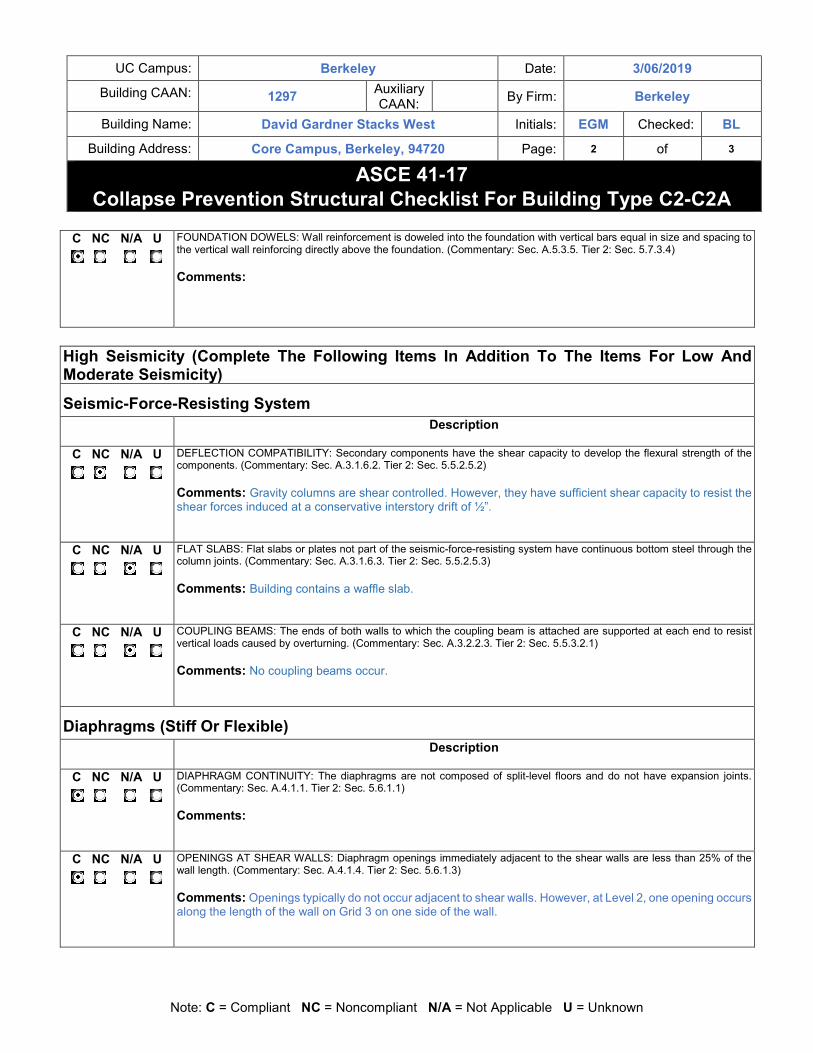
C NC N/A U
FOUNDATION DOWELS: Wall reinforcement is doweled into the foundation with vertical bars equal in size and spacing to the vertical wall reinforcing directly above the foundation. (Commentary: Sec. A.5.3.5. Tier 2: Sec. 5.7.3.4)
Comments:
High Seismicity (Complete The Following Items In Addition To The Items For Low And Moderate Seismicity)
Seismic-Force-Resisting System
Description
C NC N/A U
DEFLECTION COMPATIBILITY: Secondary components have the shear capacity to develop the flexural strength of the components. (Commentary: Sec. A.3.1.6.2. Tier 2: Sec. 5.5.2.5.2)
Comments: Gravity columns are shear controlled. However, they have sufficient shear capacity to resist the shear forces induced at a conservative interstory drift of ½”.
C NC N/A U
FLAT SLABS: Flat slabs or plates not part of the seismic-force-resisting system have continuous bottom steel through the column joints. (Commentary: Sec. A.3.1.6.3. Tier 2: Sec. 5.5.2.5.3)
Comments: Building contains a waffle slab.
C NC N/A U
COUPLING BEAMS: The ends of both walls to which the coupling beam is attached are supported at each end to resist vertical loads caused by overturning. (Commentary: Sec. A.3.2.2.3. Tier 2: Sec. 5.5.3.2.1)
Comments: No coupling beams occur.
Diaphragms (Stiff Or Flexible)
Description
C NC N/A U
DIAPHRAGM CONTINUITY: The diaphragms are not composed of split-level floors and do not have expansion joints. (Commentary: Sec. A.4.1.1. Tier 2: Sec. 5.6.1.1)
Comments:
C NC N/A U
OPENINGS AT SHEAR WALLS: Diaphragm openings immediately adjacent to the shear walls are less than 25% of the wall length. (Commentary: Sec. A.4.1.4. Tier 2: Sec. 5.6.1.3)
Comments: Openings typically do not occur adjacent to shear walls. However, at Level 2, one opening occurs along the length of the wall on Grid 3 on one side of the wall.

UC Campus: Berkeley Date: 3/06/2019
Building CAAN: 1297 Auxiliary CAAN:
By Firm: Berkeley
Building Name: David Gardner Stacks West Initials: EGM Checked: BL
Building Address: Core Campus, Berkeley, 94720 Page: 3 of 3
ASCE 41-17
Collapse Prevention Structural Checklist For Building Type C2-C2A
Note: C = Compliant NC = Noncompliant N/A = Not Applicable U = Unknown
Flexible Diaphragms
Description
C NC N/A U
CROSS TIES: There are continuous cross ties between diaphragm chords. (Commentary: Sec. A.4.1.2. Tier 2: Sec. 5.6.1.2)
Comments: Building has rigid diaphragms
C NC N/A U
STRAIGHT SHEATHING: All straight-sheathed diaphragms have aspect ratios less than 2-to-1 in the direction being considered. (Commentary: Sec. A.4.2.1. Tier 2: Sec. 5.6.2)
Comments: Building has rigid diaphragms
C NC N/A U
SPANS: All wood diaphragms with spans greater than 24 ft (7.3 m) consist of wood structural panels or diagonal sheathing. (Commentary: Sec. A.4.2.2. Tier 2: Sec. 5.6.2)
Comments: Building has rigid diaphragms
C NC N/A U
DIAGONALLY SHEATHED AND UNBLOCKED DIAPHRAGMS: All diagonally sheathed or unblocked wood structural panel diaphragms have horizontal spans less than 40 ft (12.2 m) and aspect ratios less than or equal to 4-to-1. (Commentary: Sec. A.4.2.3. Tier 2: Sec. 5.6.2)
Comments: Building has rigid diaphragms
C NC N/A U
OTHER DIAPHRAGMS: Diaphragms do not consist of a system other than wood, metal deck, concrete, or horizontal bracing. (Commentary: Sec. A.4.7.1. Tier 2: Sec. 5.6.5)
Comments: Building has rigid diaphragms
Connections
Description
C NC N/A U
UPLIFT AT PILE CAPS: Pile caps have top reinforcement, and piles are anchored to the pile caps. (Commentary: Sec. A.5.3.8. Tier 2: Sec. 5.7.3.5)
Comments: Building has strip and spread footings

APPENDIX C
UCOP Seismic Safety Policy Falling Hazards Assessment
Summary
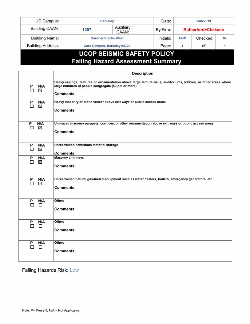
UC Campus: Berkeley Date: 3/06/2019
Building CAAN: 1297 Auxiliary CAAN:
By Firm: Rutherford+Chekene
Building Name: Gardner Stacks West Initials: EGM Checked: BL
Building Address: Core Campus, Berkeley 94720 Page: 1 of 1
UCOP SEISMIC SAFETY POLICY
Falling Hazard Assessment Summary
Note: P= Present, N/A = Not Applicable
Description
P N/A
Heavy ceilings, features or ornamentation above large lecture halls, auditoriums, lobbies, or other areas where large numbers of people congregate (50 ppl or more)
Comments:
P N/A
Heavy masonry or stone veneer above exit ways or public access areas
Comments:
P N/A
Unbraced masonry parapets, cornices, or other ornamentation above exit ways or public access areas
Comments:
P N/A
Unrestrained hazardous material storage
Comments:
P N/A
Masonry chimneys
Comments:
P N/A
Unrestrained natural gas-fueled equipment such as water heaters, boilers, emergency generators, etc.
Comments:
P N/A
Other:
Comments:
P N/A
Other:
Comments:
P N/A
Other:
Comments:
Falling Hazards Risk: Low

APPENDIX D
Quick Check Calculations
RUTHERFORD + CHEKENE TIER 1 EVALUATION
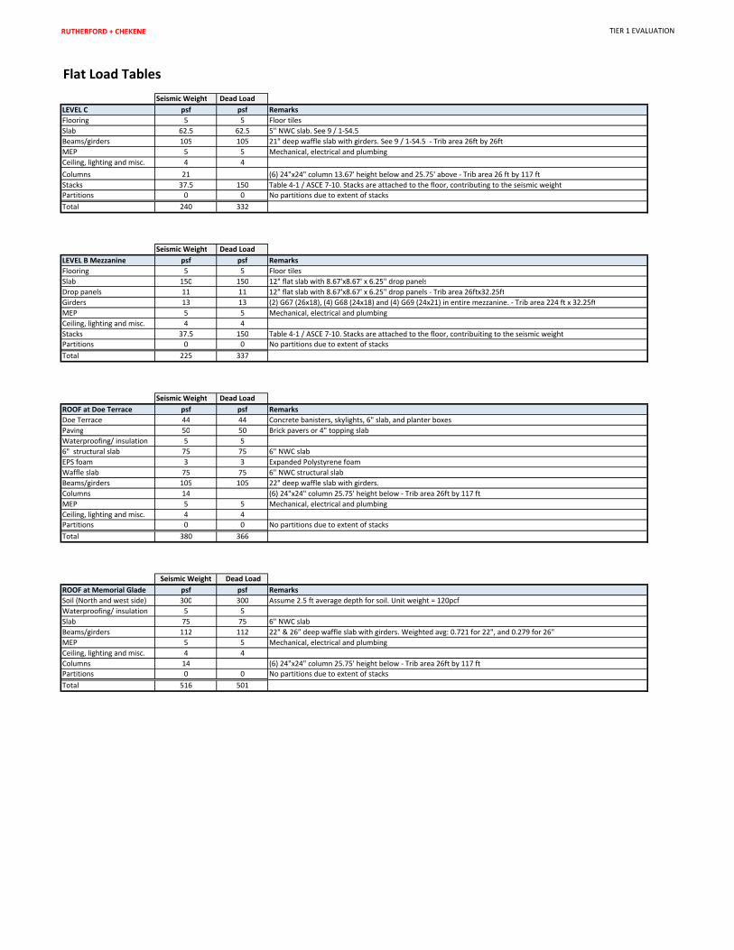
Flat Load Tables
Seismic Weight Dead Load
LEVEL C psf psf Remarks
Flooring 5 5 Floor tiles
Slab 62.5 62.5 5" NWC slab. See 9 / 1-S4.5
Beams/girders 105 105 21" deep waffle slab with girders. See 9 / 1-S4.5 - Trib area 26ft by 26ft
MEP 5 5 Mechanical, electrical and plumbing
Ceiling, lighting and misc. 4 4
Columns 21 (6) 24"x24" column 13.67' height below and 25.75' above - Trib area 26 ft by 117 ft
Stacks 37.5 150 Table 4-1 / ASCE 7-10. Stacks are attached to the floor, contributing to the seismic weight
Partitions 0 0 No partitions due to extent of stacks
Total 240 332
Seismic Weight Dead Load
LEVEL B Mezzanine psf psf Remarks
Flooring 5 5 Floor tiles
Slab 150 150 12" flat slab with 8.67'x8.67' x 6.25" drop panels
Drop panels 11 11 12" flat slab with 8.67'x8.67' x 6.25" drop panels - Trib area 26ftx32.25ft
Girders 13 13 (2) G67 (26x18), (4) G68 (24x18) and (4) G69 (24x21) in entire mezzanine. - Trib area 224 ft x 32.25ft
MEP 5 5 Mechanical, electrical and plumbing
Ceiling, lighting and misc. 4 4
Stacks 37.5 150 Table 4-1 / ASCE 7-10. Stacks are attached to the floor, contribuiting to the seismic weight
Partitions 0 0 No partitions due to extent of stacks
Total 225 337
Seismic Weight Dead Load
ROOF at Doe Terrace psf psf Remarks
Doe Terrace 44 44 Concrete banisters, skylights, 6" slab, and planter boxes
Paving 50 50 Brick pavers or 4" topping slab
Waterproofing/ insulation 5 5
6" structural slab 75 75 6" NWC slab
EPS foam 3 3 Expanded Polystyrene foam
Waffle slab 75 75 6" NWC structural slab
Beams/girders 105 105 22" deep waffle slab with girders.
Columns 14 (6) 24"x24" column 25.75' height below - Trib area 26ft by 117 ft
MEP 5 5 Mechanical, electrical and plumbing
Ceiling, lighting and misc. 4 4
Partitions 0 0 No partitions due to extent of stacks
Total 380 366
Seismic Weight Dead Load
ROOF at Memorial Glade psf psf Remarks
Soil (North and west side) 300 300 Assume 2.5 ft average depth for soil. Unit weight = 120pcf
Waterproofing/ insulation 5 5
Slab 75 75 6" NWC slab
Beams/girders 112 112 22" & 26" deep waffle slab with girders. Weighted avg: 0.721 for 22", and 0.279 for 26"
MEP 5 5 Mechanical, electrical and plumbing
Ceiling, lighting and misc. 4 4
Columns 14 (6) 24"x24" column 25.75' height below - Trib area 26ft by 117 ft
Partitions 0 0 No partitions due to extent of stacks
Total 516 501

RUTHERFORD + CHEKENE TIER 1 EVALUATION
Story Weight
Floor Levels LEVEL C (ft2)
LEVEL B
Mezzanine (ft2)
ROOF At
Terrace (ft2)
Roof at
Memorial Glade
(ft2) LEVEL C (ft
2)
LEVEL B
Mezzanine (ft2)
ROOF At
Terrace (ft2)
Roof at
Memorial Glade
(ft2)
Wall height
below
(ft)
Trib Wall Height
[above & below]
(ft)
Wall Area
(ft2)
Wall
Weight
(kips)
Wall Seismic
Weight
(kips)
Total Seismic
Weight
(kips)
Roof 3,612 11,346 21,353 240 225 380 516 25.8 12.9 1137.6 4394 2197 18,334
LEVEL C 29,810 3,612 240 225 380 516 13.7 19.7 967.6 1984 3189 11,164
Notes: Total Weight = 29,498
1 - Levels as indicated on the drawings are shown below. Level names were revised during construction: 29,498
Drawing
Name
Constructed
Name
Roof Roof
Level C Level 2
Level D Level 1
2 - Seismic base of embedded building is set as Level D which is slab-on-grade. Soil Structure interaction is ignored.
3 - Low roof slopes. Elevation set to match high point of the Roof which is also the elevationof the Doe Entry Terrace
4 - Level B Mezzanine mass is split equally between the Roof and Level C
Area Unit weight

RUTHERFORD + CHEKENE TIER 1 EVALUATION
Period
Ct= 0.02
hn (ft)= 39.41
B= 0.75
T= 0.31 sec
Notes:
1- Period calculated per ASCE 41-17 Equation 4-4
2- Ct and B are for "all other framing system" per ASCE 41-17
Section 4.4.2.4

RUTHERFORD + CHEKENE TIER 1 EVALUATION
Site Parameters
Period Sa
0 0.9252
0.07 2.313
0.37 2.313
0.62 1.377
0.87 0.980
1.00 0.850
1.25 0.680
1.50 0.567
1.75 0.486
2.00 0.425
2.25 0.378
2.50 0.340
2.75 0.309
3.00 0.283
3.25 0.262
SxS = 2.313 g
Sx1 = 0.850 g
To = 0.07 s
Ts = 0.37 s
Sa= 2.313 g
T= 0.31 s
Notes:
1- Site Specific spectral accelerations are based upon the soil type and rock profile provided in the report "2015 Update to the Site-Specific Seismic Hazard
Analyses and Development of Seismic Design Ground Motions, UC Berkeley, 15 July 2015 by URS Corporation. The procedure as specified in ASCE 7-16,
Section 21.4 is used to develop the Design Response Spectrum shown above.
0
0.5
1
1.5
2
2.5
0 0.5 1 1.5 2 2.5 3 3.5
Sp
ect
ral
Acc
ele
rati
on
(g
)
Period (sec)
BSE-2E Response Spectrum
RUTHERFORD + CHEKENE TIER 1 EVALUATION
Seismic Force Distribution
Sa= 2.31
W= 29,498 kips
C= 1.2
Per ASCE 41-17
Table 4-7
V= 81,876 kips
k= 1.00 Per ASCE 41-17 Section 4.4.2.2, K = 1.0 for periods less than 0.5 sec
Story Shears
Floor Levels Story Height Total Height, H Weight, W W x Hk
coeff Fx Story Shear, V
(ft) (ft) (kips) (kips) (kips)
Roof 25.75 39.42 18,334 722,728 0.83 67,601 67,601
Level C 13.67 13.67 11,164 152,617 0.17 14,275 81,876
875,345 1.00 81,876
Notes:
1- Base of building is assumed to be at Level D which is the lowest below grade level
2- Soil surrounding embedded structure is assumed to not contribute to the base shear
3- Modification Factor, C, per ASCE 41-17, Table 4-7
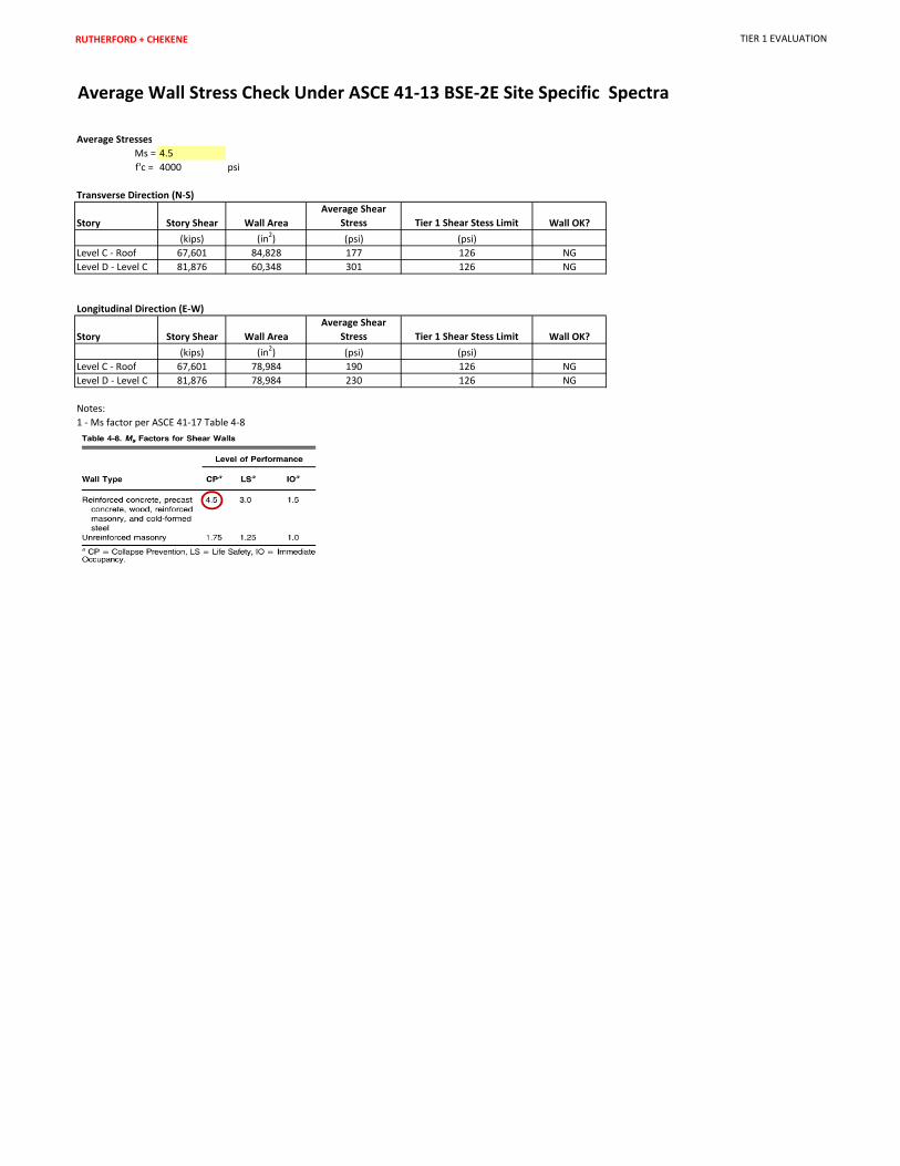
RUTHERFORD + CHEKENE TIER 1 EVALUATION
Average Wall Stress Check Under ASCE 41-13 BSE-2E Site Specific Spectra
Average Stresses
Ms = 4.5
f'c = 4000 psi
Transverse Direction (N-S)
Story Story Shear Wall Area
Average Shear
Stress Tier 1 Shear Stess Limit Wall OK?
(kips) (in2) (psi) (psi)
Level C - Roof 67,601 84,828 177 126 NG
Level D - Level C 81,876 60,348 301 126 NG
Longitudinal Direction (E-W)
Story Story Shear Wall Area
Average Shear
Stress Tier 1 Shear Stess Limit Wall OK?
(kips) (in2) (psi) (psi)
Level C - Roof 67,601 78,984 190 126 NG
Level D - Level C 81,876 78,984 230 126 NG
Notes:
1 - Ms factor per ASCE 41-17 Table 4-8

RUTHERFORD + CHEKENE TIER 1 EVALUATION
Average Wall Stress Check Under ASCE 7-10 Site Specific Design Response Spectra
Sa (ASCE 7-10) = 1.71 See Note 2
Sa (ASCE 7-10 DBE)/Sa BSE-2E = 0.74
R = 5 Detailing is equivalent to a Special Bearing Wall System
Transverse Direction (N-S)
Story
BSE 2
Story Shear
ASCE 7-10
Story Shear Wall Area
Average Shear
Stress
Shear Stress
Limit Wall OK?
(kips) (kips) (in2) (psi)
Level C - Roof 67,601 49,977 84,828 118 214 OK
Level D - Level C 81,876 60,531 60,348 201 214 OK
Longitudinal Direction (E-W)
Story
BSE 2
Story Shear
ASCE 7-10
Story Shear Wall Area
Average Shear
Stress
Shear Stress
Limit Wall OK?
(kips) (kips) (in2) (psi)
Level C - Roof 67,601 49,977 78,984 127 214 OK
Level D - Level C 81,876 60,531 78,984 153 214 OK
Notes:
1- Reinforcing is #4@ 12" o.c. E.W., E.F as a minimum, f'c = 4000 psi, φ= 0.60, αc x sqrt (f'c), αc = 3 due to 1H:1V wall aspect ratio
2- Site Specific spectral accelerations are based upon the soil type and rock profiles provided in the report "2015 Update to the Site-Specific Seismic Hazard Analyses and Development of
Seismic Design Ground Motions, UC Berkeley, 15 July 2015 by URS Corporation for ASCE7-10. The procedure as specified in ASCE 7-10, Section 21.4 is used to develop the Design Response
Spectrum.

RUTHERFORD + CHEKENE TIER 1 EVAULATION
COLUMN DEFORMATION COMPATIBILTY (0.9DL)
Material properties
- Concrete f'c 4 ksi Based upon drawings
- Steel rebar fy 60 ksi Based upon drawings
Other parameters
- Flexural ductility knl 0.7
- Lightweight λ 1.0
b (in) h (in) AG (in2) D (in) AS (in
2) D (in) AV (in
2) d' (in) dc (in) hb (in) L (ft) Ln (in) s/d αcol Ln/2dc MU/VUd 6f
0.5/(M/Vd) NUG (k)
1x (ft) y (ft) Atrib (ft
2) (1+N/6Af
0.5)0.5
VS (k) VC (k) Vcol (k) 2
MP=0 (k-ft) 3
M (k-ft)3 2M/L (k) Vp/Vn E (ksi) I g(in
2) Δ (in) L (in) Vprob (k)
4Acceptance criteria
5
#B-4 (1-A)-1F-24X24-8#8 B-4 (1-A) 1 24 24 576 8 #8 1 6.3 3.4 #4 12 0.5 0.67 2 21.50 21 13.666 142.99 0.56 1.0 3.3 3.3 0.11 524 26 26 676 1.8 71.8 96.9 118.1 416.2 772.5 129.7 Shear 1.10 3605.0 27648.0 0.5 164.0 67.8 OK
#B-4 (1-A)-2F-24X24-8#8 B-4 (1-A) 2 24 24 576 8 #8 1 6.3 3.4 #4 12 0.5 0.67 2 21.50 22 17.67 190.04 0.56 1.0 4.4 4.0 0.09 315 26 26 676 1.6 71.8 68.3 98.0 416.2 656.8 82.9 Flexure 0.85 3605.0 27648.0 0.5 212.0 31.4 -
#E-4 (1-B)-1F-24X24-8#11 E-4 (1-B) 1 24 24 576 8 #11 1.41 12.5 3.0 #4 12 0.5 0.59 2 21.30 21 13.666 142.99 0.56 1.0 3.4 3.4 0.11 663 26 26.5 689 2.0 62.7 104.6 117.1 783.3 1110.0 186.3 Shear 1.59 3605.0 27648.0 0.5 164.0 67.8 OK
#E-4 (1-B)-2F-24X24-8#11 E-4 (1-B) 2 24 24 576 8 #11 1.41 12.5 3.0 #4 12 0.5 0.59 2 21.30 18.25 12 125.75 0.56 1.0 3.0 3.0 0.13 450 26 26.5 689 1.7 62.7 103.6 116.4 783.3 1033.2 197.2 Shear 1.69 3605.0 27648.0 0.5 144.0 100.1 OK
#E-4 (1-A)-MF-24X24-8#8 E-4 (1-A) M 24 24 576 8 #8 1 6.3 3.4 #4 12 0.5 0.67 2 21.50 22 13.75 143 0.56 1.0 3.3 3.3 0.11 235 26 26.5 689 1.4 71.8 75.7 103.2 416.2 600.1 100.7 Flexure 0.98 3605.0 27648.0 0.5 165.0 66.6 -
Notes:
1- Based on 0.9DL
2 - Shear capacity of column is based on ASCE 41-17 Eq 10-3 using nominal material strengths with φ =1.0
αcol = 1.0 for s/d <= 0.75, 0.0 for s/d >=1.0
3 - Plastic moment capacity of the column is based upon expected flexural strength using 1.5 f'c and 1.25 fy
4 - Shear induced due to drift of a fixed-fixed column
5- Vprob is compared to Vcol. If Vprob <Vcol, Shear failure is not likely to occur.
ADDITIONAL CHECK (LIMITED BY DRIFT)SHEAR/FLEX
CONTROLn-# n-#-s (in)
DIMENSION CONFINEMENT FLEXYIELD AXIAL SHEAR FLEXURETRANVERSEspColumn
Model
Col Location
(Column Type)Level
SIZE LONGITUDINAL
RUTHERFORD + CHEKENE TIER 1 EVAULATION
COLUMN DEFORMATION COMPATIBILTY (1.1DL+0.275LL)
Material properties
- Concrete f'c 4 ksi Based upon drawings
- Steel rebar fy 60 ksi Based upon drawings
Other parameters
- Flexural ductility knl 0.7
- Lightweight λ 1.0
b (in) h (in) AG (in2) D (in) AS (in
2) D (in) AV (in
2) d' (in) dc (in) hb (in) L (ft) Ln (in) s/d αcol Ln/2dc MU/VUd 6f
0.5/(M/Vd) NUG (k)
1 x (ft) y (ft) Atrib (ft2) (1+N/6Af
0.5)0.5 VS (k) VC (k) Vcol (k)
2MP=0 (k-ft)
3M (k-ft)
3 2M/L (k) Vp/Vn E (ksi) I g(in2) Δ (in) L (in) Vprob (k)
4Acceptance criteria
5
#B-4 (1-A)-1F-24X24-8#8 B-4 (1-A) 1 24 24 576 8 #8 1 6.3 3.4 #4 12 0.5 0.67 2 21.50 21 13.7 143.0 0.56 1.0 3.3 3.3 0.11 668 26 26 676 2.0 71.8 105.9 124.4 416.2 833.1 139.8 Shear 1.12 3605.0 27648.0 0.5 164.0 67.8 OK
#B-4 (1-A)-2F-24X24-8#8 B-4 (1-A) 2 24 24 576 8 #8 1 6.3 3.4 #4 12 0.5 0.67 2 21.50 22 17.7 190.0 0.56 1.0 4.4 4.0 0.09 403 26 26 676 1.7 71.8 73.7 101.8 416.2 714.9 90.3 Flexure 0.89 3605.0 27648.0 0.5 212.0 31.4 -
#E-4 (1-B)-1F-24X24-8#11 E-4 (1-B) 1 24 24 576 8 #11 1.41 12.5 3.0 #4 12 0.5 0.59 2 21.30 21 13.7 143.0 0.56 1.0 3.4 3.4 0.11 839 26 26.5 689 2.2 62.7 114.6 124.1 783.3 1167.3 195.9 Shear 1.58 3605.0 27648.0 0.5 164.0 67.8 OK
#E-4 (1-B)-2F-24X24-8#11 E-4 (1-B) 2 24 24 576 8 #11 1.41 12.5 3.0 #4 12 0.5 0.59 2 21.30 18.25 12.0 125.8 0.56 1.0 3.0 3.0 0.13 579 26 26.5 689 1.9 62.7 113.1 123.1 783.3 1080.4 206.2 Shear 1.68 3605.0 27648.0 0.5 144.0 100.1 OK
#E-4 (1-A)-MF-24X24-8#8 E-4 (1-A) M 24 24 576 8 #8 1 6.3 3.4 #4 12 0.5 0.67 2 21.50 22 13.8 143.0 0.56 1.0 3.3 3.3 0.11 306 26 26.5 689 1.5 71.8 81.4 107.2 416.2 650.6 109.2 Shear 1.02 3605.0 27648.0 0.5 165.0 66.6 OK
Notes:
1- Based on 1.1DL+0.275LL
2 - Shear capacity of column is based on ASCE 41-17 Eq 10-3 using nominal material strengths with φ =1.0
αcol = 1.0 for s/d <= 0.75, 0.0 for s/d >=1.0
3 - Plastic moment capacity of the column is based upon expected flexural strength using 1.5 f'c and 1.25 fy
4 - Shear induced due to drift of a fixed-fixed column
5- Vprob is compared to Vcol. If Vprob <Vcol, Shear failure is not likely to occur.
ADDITIONAL CHECK (LIMITED BY DRIFT)spColumn
Model
Col Location
(Column Type)Level
SIZE LONGITUDINALSHEAR/FLEX
CONTROLn-# n-#-s (in)
DIMENSION CONFINEMENT FLEXYIELD AXIAL SHEAR FLEXURETRANVERSE