uconn utas phm · senior design ece 4901 electro-mechanics prof. ali bazzi 10/03/2016...
TRANSCRIPT

2
Introduction
10/3/2016
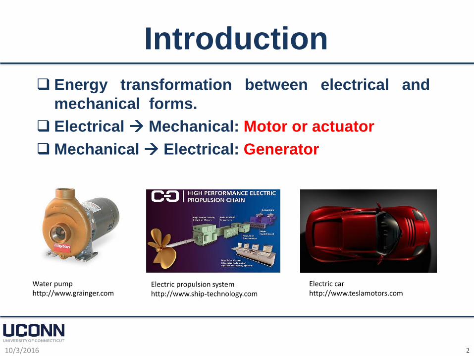
Energy transformation between electrical and
mechanical forms.
Electrical Mechanical: Motor or actuator
Mechanical Electrical: Generator
Electric car http://www.teslamotors.com
Water pump http://www.grainger.com
Electric propulsion system http://www.ship-technology.com
3
Introduction
10/3/2016
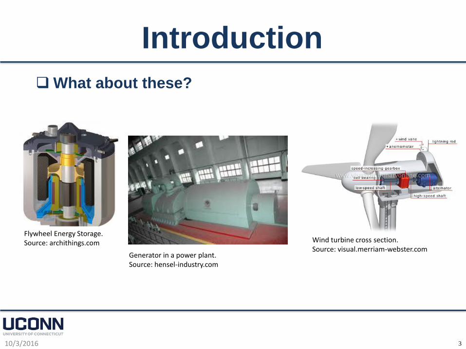
What about these?
Wind turbine cross section. Source: visual.merriam-webster.com
Flywheel Energy Storage. Source: archithings.com
Generator in a power plant.Source: hensel-industry.com
4
Energy Conversion
10/3/2016
It is common to have an intermediate couplingstage between electrical and mechanical energytransformations: Electromagnetics!
Among the electromechanical energy conversiondevices that can be used in senior designprojects:
ElectromechanicalRelays
Transformers
Single-phase motors
Three-phase motors/generators
Stepper motors
5
Relays
10/3/2016
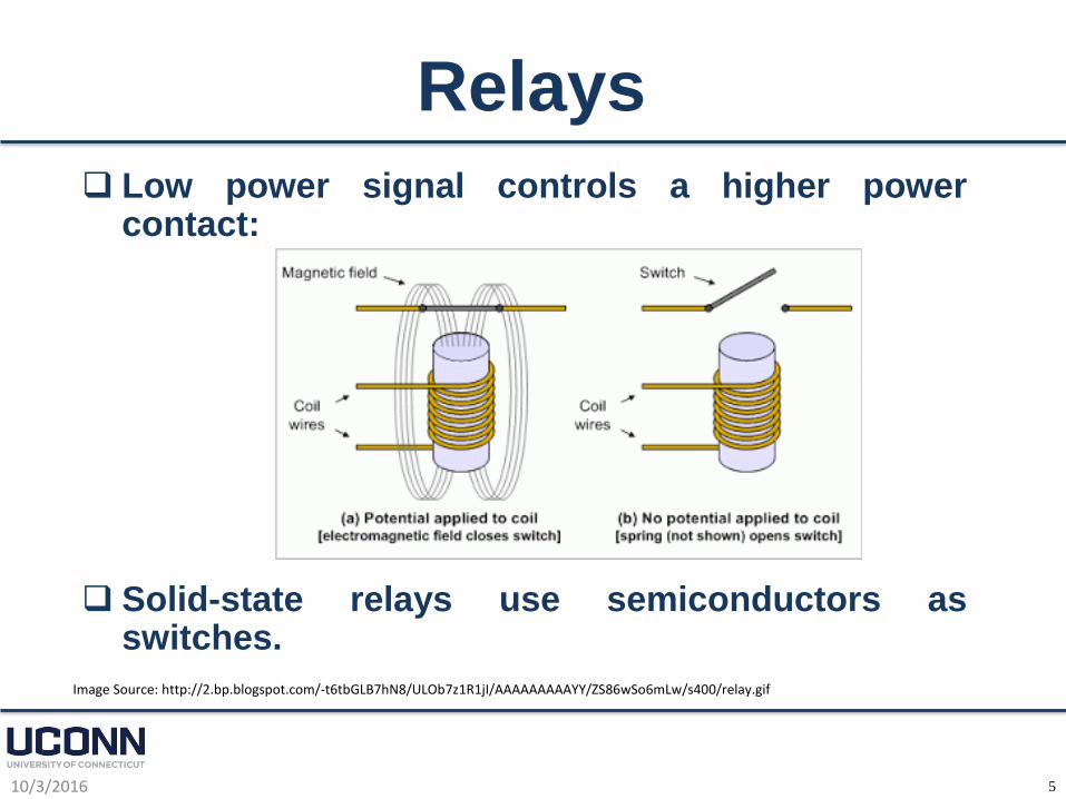
Low power signal controls a higher powercontact:
Solid-state relays use semiconductors asswitches.
Image Source: http://2.bp.blogspot.com/-t6tbGLB7hN8/ULOb7z1R1jI/AAAAAAAAAYY/ZS86wSo6mLw/s400/relay.gif
6
Transformers
10/3/2016
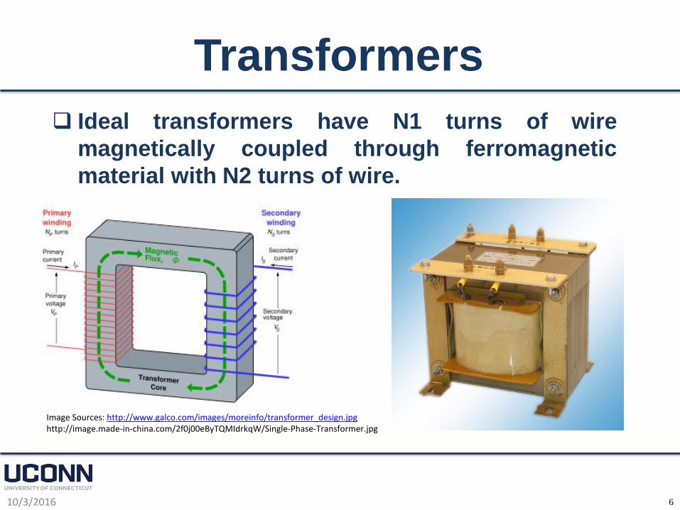
Ideal transformers have N1 turns of wire
magnetically coupled through ferromagnetic
material with N2 turns of wire.
Image Sources: http://www.galco.com/images/moreinfo/transformer_design.jpghttp://image.made-in-china.com/2f0j00eByTQMIdrkqW/Single-Phase-Transformer.jpg
7
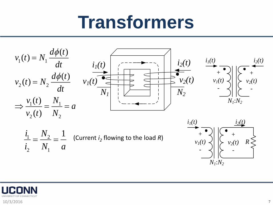
Transformers
10/3/2016
v1(t) v2(t)
i1(t) i2(t)
N1 N2
1 1
2 2
1 1
2 2
( )( )
( )( )
( )
( )
d tv t N
dt
d tv t N
dt
v t Na
v t N
+
v1(t)
-
+
v2(t)
-
i1(t) i2(t)
N1:N2
1 2
2 1
1i N
i N a (Current i2 flowing to the load R)
+
v1(t)
-
+
v2(t)
-
i1(t) i2(t)
N1:N2
R

8
Three-Phase Rotating Magnetic Field
10/3/2016
Three-phase balanced (magnitude, frequency, and 120
degrees of phase shift) currents flowing through
sinusoidally spaced three-phase windings produce a
rotating magnetic field.
Image Sources: http://www.basilnetworks.com/article/motors/images/motor2pole.gifhttp://electriciantraining.tpub.com/14177/img/14177_91_1.jpg
9
Three-Phase Rotating Machines
10/3/2016
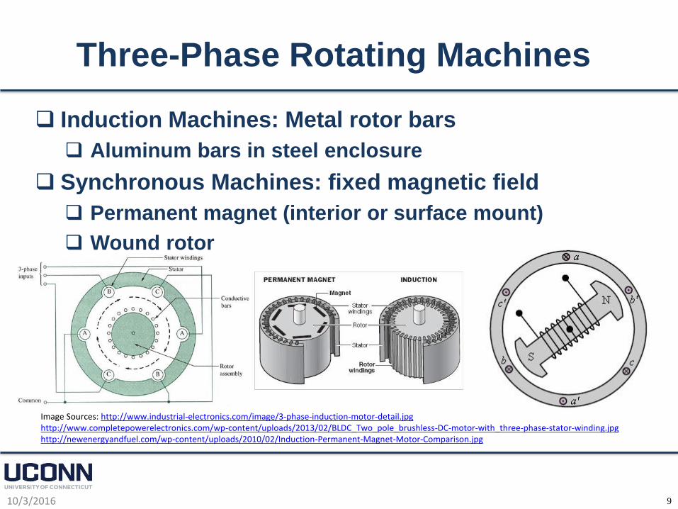
Induction Machines: Metal rotor bars
Aluminum bars in steel enclosure
Synchronous Machines: fixed magnetic field
Permanent magnet (interior or surface mount)
Wound rotor
Image Sources: http://www.industrial-electronics.com/image/3-phase-induction-motor-detail.jpghttp://www.completepowerelectronics.com/wp-content/uploads/2013/02/BLDC_Two_pole_brushless-DC-motor-with_three-phase-stator-winding.jpghttp://newenergyandfuel.com/wp-content/uploads/2010/02/Induction-Permanent-Magnet-Motor-Comparison.jpg
10
Stepper Motors
10/3/2016
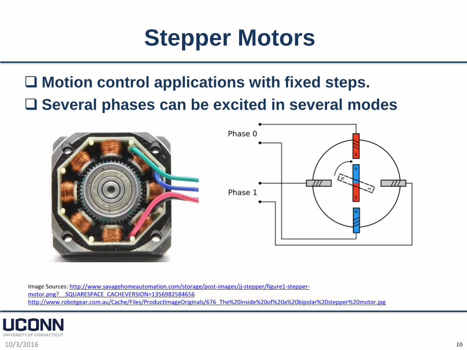
Motion control applications with fixed steps.
Several phases can be excited in several modes
Image Sources: http://www.savagehomeautomation.com/storage/post-images/jj-stepper/figure1-stepper-motor.png?__SQUARESPACE_CACHEVERSION=1356982584656http://www.robotgear.com.au/Cache/Files/ProductImageOriginals/676_The%20inside%20of%20a%20bipolar%20stepper%20motor.jpg

11
Electric Drives
10/3/2016
Speed, torque, and motion control require power
electronics to modify voltage and current signals.
Typical drives are shown in the next slides.
Control of power electronic switches is provided
by:
Microcontrollers (PIC, MSP430, Altec, etc.)
FPGAs (Xilinx, NI, etc.)
Digital Signal Processors (TMS from TI, etc.)
Analog control circuitry
12
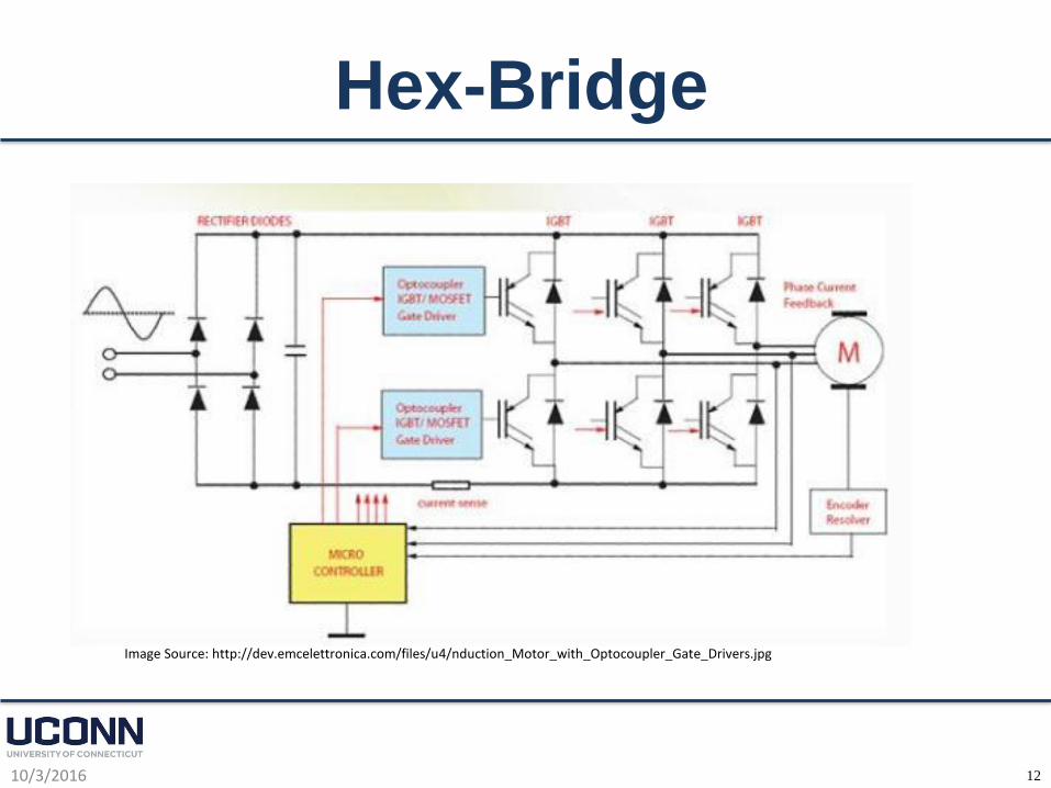
Hex-Bridge
10/3/2016
Image Source: http://dev.emcelettronica.com/files/u4/nduction_Motor_with_Optocoupler_Gate_Drivers.jpg
13
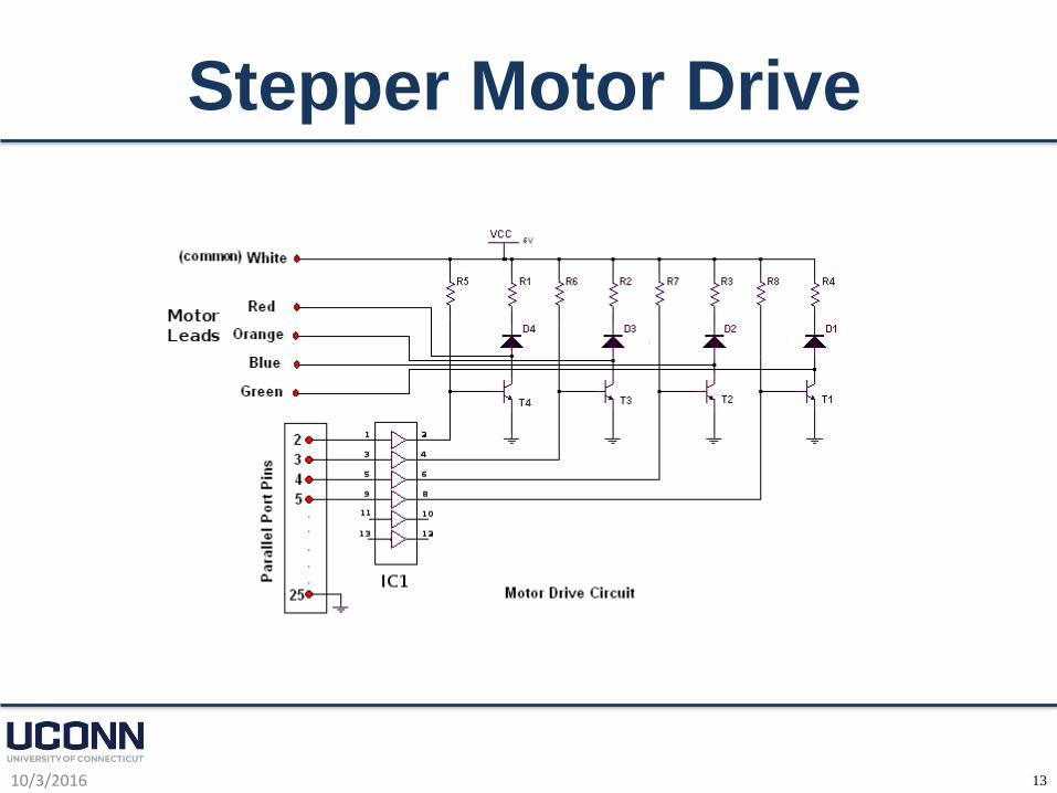
Stepper Motor Drive
10/3/2016
14
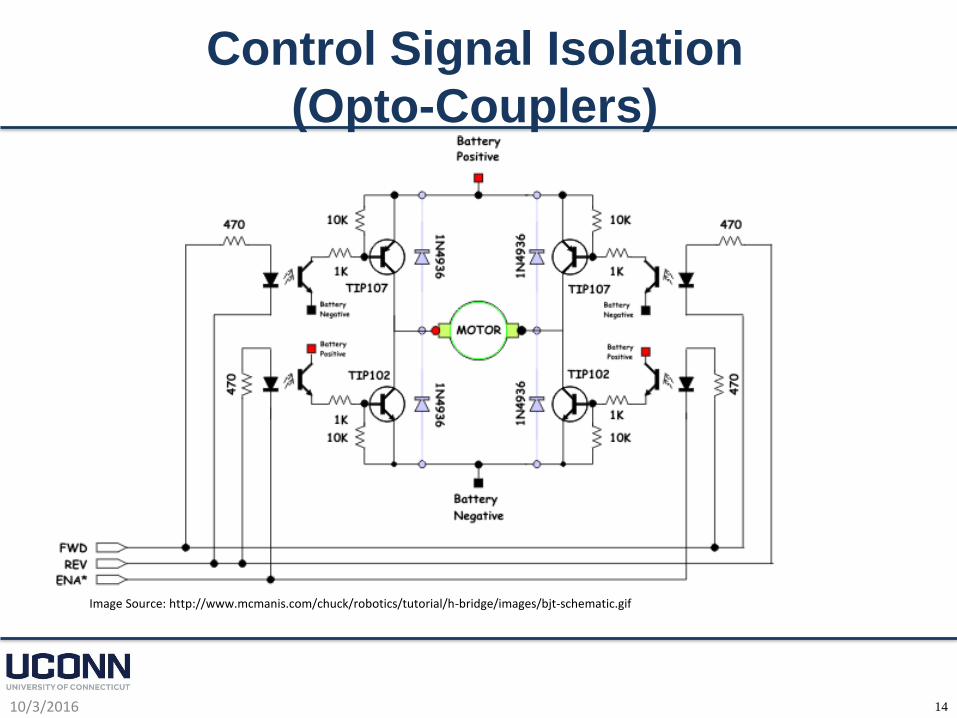
Control Signal Isolation
(Opto-Couplers)
10/3/2016
Image Source: http://www.mcmanis.com/chuck/robotics/tutorial/h-bridge/images/bjt-schematic.gif
15
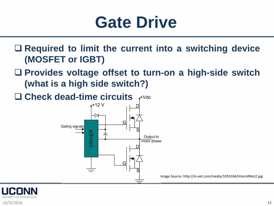
Gate Drive
10/3/2016
Required to limit the current into a switching device
(MOSFET or IGBT)
Provides voltage offset to turn-on a high-side switch
(what is a high side switch?)
Check dead-time circuits
Image Source: http://m.eet.com/media/1055164/IntersilMot2.jpg
16
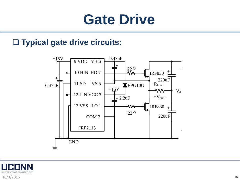
Gate Drive
10/3/2016
Typical gate drive circuits:
+15V
+15V
+
Vdc
-
0.47uF
2.2uF
EPG10G
22ΩIRF830
IRF830
220uF
220uF
RLoad
+Vout-
9 VDD VB 6
10 HIN HO 7
11 SD VS 5
12 LIN VCC 3
13 VSS LO 1
COM 2
IRF2113
0.47uF
22Ω
GND
+
+
+
+
+
17
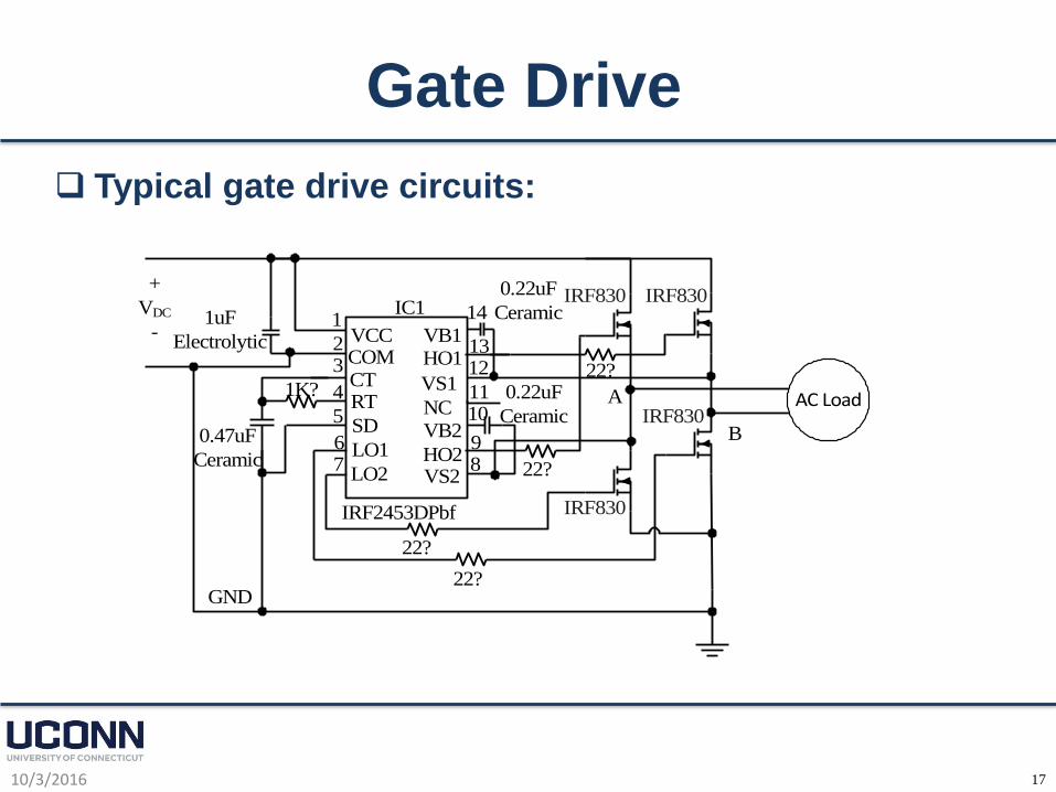
Gate Drive
10/3/2016
Typical gate drive circuits:
VCCCOMCTRT
SD
LO1
LO2
VB1HO1
HO2
VS1
VB2
VS2
NC
IRF2453DPbf
1uF
Electrolytic
0.47uF
Ceramic
0.22uF
Ceramic
0.22uF
Ceramic
1K?
IRF830 IRF830
IRF830
IRF830
IC1
GND
22?
22?
22?
22?
1
23
4
5
67 8
9
1011
1213
14
+
VDC
-
A
B
AC Load