uav concordia - auvsi suas · uav concordia . journal paper for ... in order to maximize flight...
TRANSCRIPT

2
UAV Concordia Journal Paper for the AUVSI Student UAS Competition
Abstract This document will provide to the reader a proposal in response to a bid launched by the Association for Unmanned Aerial Systems International to all international undergraduate design teams in the context of the 15th Student Unmanned Aerial Systems (UAS), aiming to put students in a simulation. The tasks involved in this simulation require a system capable of numerous advanced features including autonomous flight, navigation and automated target detection. The UAV Concordia team offers a solution to those challenges which was elaborated by undergraduate students mostly from the faculties of software, electrical and mechanical engineering. This year’s competition shall be the first attempt by the UAV Concordia team to compete on the field and thus the efforts have been focused on achieving the two primary tasks along some secondary tasks.

3
Table of Contents
1. Systems Engineering Approach ........................................................................................................................... 4
1.1. Mission Requirements Analysis of Planned Tasks ...................................................................................... 4
1.2. Design Rationale .......................................................................................................................................... 5
1.3. Expected Task Performance ......................................................................................................................... 6
1.4. Programmatic Risks and Mitigation Methods .............................................................................................. 6
1.5. Description of the UAS Design .................................................................................................................... 8
2. Design .................................................................................................................................................................. 9
2.1. Aircraft ......................................................................................................................................................... 9
2.2. Propulsion .................................................................................................................................................. 11
2.3. Avionics ..................................................................................................................................................... 11
2.4. Data Link ................................................................................................................................................... 12
2.5. Interoperability Requirements .................................................................................................................... 12
2.6. Payload Release Mechanism ...................................................................................................................... 13
2.7. Ground Control System .............................................................................................................................. 14
2.8. Data Processing .......................................................................................................................................... 14
2.9. Mission Planning ........................................................................................................................................ 15
2.10. Autonomous Target Detection ................................................................................................................... 16
3. Test and Evaluation Results ............................................................................................................................... 17
3.1. Mission Task Performance ......................................................................................................................... 17
3.2. Payload System Performance ..................................................................................................................... 19
3.3. Autopilot System Performance .................................................................................................................. 19
3.3.1. Waypoint Navigation ........................................................................................................................ 19
3.3.2. Autonomous Search Area .................................................................................................................. 19
3.3.3. Interoperability Task ......................................................................... Error! Bookmark not defined.
4. Safety Considerations ........................................................................................................................................ 20
4.1. Safety Criteria ............................................................................................................................................ 20
4.2. Safety Risk Mitigation ............................................................................................................................... 20
4.3. Design Safety Criteria ................................................................................................................................ 21
5. Conclusions ........................................................................................................................................................ 21

4
1. SYSTEMS ENGINEERING APPROACH
1.1. MISSION REQUIREMENTS ANALYSIS OF PLANNED TASKS
The development process of the UAV to be used during the competition has been carried out with special
consideration to the various tasks and objectives outlined in the competition rules. In all, our platform was arranged
in order to maximize flight time while ensuring a structural integrity of the frame, integrated image processing
capabilities and reliable signal transmission.
• All primary objectives are expected to be achieved. Several optional objectives are also considered to
be fully achievable
o Autonomous Flight Task
o Search Area Task
• Objectives that will be attempted:
o Actionable Intelligence Task
o Off-Axis Task
o Payload Drop
o Emergent Target Task
o Interoperability Task
• Objectives that will not be attempted
o Automatic Detection, Localization, and Classification (ADLC) Task
o Simulated Remote Information Center (SRIC) Task
o Sense, detect and avoid (SDA) Task

5
1.2. DESIGN RATIONALE
• Battery Configuration
o The main criterion in selecting the most appropriate battery configuration for our drone included the
following requirements;
The voltage output for the batteries must be in accordance with the 22.2V of voltage
required for the propeller motors. As such, a 6-cell lithium-polymer battery is to be used.
The energy capacity of the battery should allow for flight times of up to 22 minutes. For
that reason, a battery with a capacity of 16,000 mAh was selected.
The discharge capacity must provide a burst discharge capacity of 20C for 10 seconds,
resulting in 320 Amps. The steady-state discharge rate must be of 10C, resulting in 160
Amps.
o For the reasons listed above, the batteries used are 6S LiPo, 16,000 mAh.
• Arm Configuration
o Prior to deciding what type of arm configuration would be used for the design of the drone, research
was performed on the advantages and disadvantages of each configuration. This research effort has
led us to the conclusion that a standard six arm configuration (hexacopter) would be the most
appropriate for our needs for the following reasons:
Relative ease of construction and assembly when compared with other layouts (e.g. Y-arm
setup, matrix, etc.)
Abundance of reference information available online due to the fact that this type of
platform is commonly used.
• Image Processing System
o The system to be used for automated shape and character recognition is the CMUcam5 Pixy. It
consists of an image sensor paired with a dedicated processor used for object detection. The main
performance advantage provided with this system is the elimination of the need for post-processing
the images on a PC.

6
• Ground Control System
o The graphical user interface to be used during the competition is called Mission Planner. It is used
to communicate with the drone via radio signal, receive telemetry data and send mission updates
back to the UAV.
• Autopilot
o The autopilot used on our UAV is the Pixhawk module from 3DRobotics. This system provides our
platform with a range of possibilities. The Pixhawk module is an open source project and it is highly
versatile as it is compatible with numerous platforms and configurations. The company developing
this system, 3DRobotics, has extensive experience in developing avionics controllers and as such,
it was decided that their system would be the most appropriate for our system.
1.3. EXPECTED TASK PERFORMANCE
The current year UAV platform (Condor II) is significantly larger than any other drone previously built by the
society. This larger platform can accommodate more equipment including payload release mechanisms and imaging
sensors. Additionally, the newer platform provides sufficient space for larger capacity batteries to be installed, thus
ensuring the UAV can achieve the flight times expected for the completion of objectives.
1.4. PROGRAMMATIC RISKS AND MITIGATION METHODS
Risk Factor Description Risk Level Impact Mitigation Method
Design and Manufacturing
stage delays
Delays in the design or manufacturing phases of the project may impede on the team’s ability to present a
working system to the competition.
Medium High
Platforms used in previous years for different competitions are being maintained in a valid operating
condition so that they may be used as a backup solution.
Compliance with Competition
Rules
The UAV and all of its systems bust be in accordance with the
terms specified in the competition rules.
Low High
Analysis and reviewing of the competition rules has been performed on several meetings early in the design
process.

7
Legal Issues and Insurance
The UAV must be properly insured and must be legally
allowed to operate in the jurisdictions in which it will fly.
Low High
• A dedicated officer in our Executive Committee has been in charge of making sure the system
was in compliance with the applicable jurisdiction regulations.
• Matters of insurance have been dealt with very early in the process of planning our participation in the
competition.
Target Recognition
Software Issues
Different weather condition may alter the UAV’s ability to detect
and identify various targets essential in completing the
objectives.
High Medium
Testing will be performed prior to the competition with various cardboard or
wood cutouts to be tested with the CMUcam5 Pixy.
Flight Test Crash
Flight tests may result in a crash that could damage some of the
UAV’s most critical components.
Medium Medium
• Some of the most critical components (motors, propellers,
battery) have been ordered in quantities exceeding those required, thus providing us with spare parts.
• The drone used for the current-year competition was assembled entirely from new parts while maintaining the previous year drone as backup.
Image Processing Issues
The CMUcam5 Pixy is currently the system relied upon
to perform the shape and character recognition. Technical
issues could significantly compromise our ability to achieve several objectives
during the competition.
Medium Medium
A non-automated method for detecting shaped and characters in the images will be kept available in case the CMUcam5
Pixy fails.
In addition to the programmatic risks listed above, budget limitations also constitute uncertainty in whether the drone
design will be carried out through all of its phases in time for the competition. Unexpected expenditures along the
manufacturing stage, if significant enough, may compromise our ability to complete the UAV. In the event that it
would be foreseeable that our drone design would not be ready in time, a standard frame platform would be purchased.
The electrical and software systems designed would then be integrated to the platform.

8
1.5. DESCRIPTION OF THE UAS DESIGN
Figure 1- Complete Assembly of Condor II
Table 1- Aircraft Specifications
Frame Hub Armature Aircraft Dimensions Length 328mm Length 392mm Length (Motor to Motor) 960mm Thickness 1.5mm Diameter 25mm Height (From Rails to ground 320mm
Performance Propulsion Max Speed RPM/Volts 340KV Average Cruising Speed
.. Maximum Thrust
9KG
Max Flight Time 22 mins
Prop. Size 16X5.4CF
MTOW 8KG Battery 16Ahr, 22.22V
Total Weight at Take Off
6.5KG

9
2. DESIGN
2.1. AIRCRAFT
During the early stages of development, a set of core design aspects were taken into account. The platform to be design
was to be as light as possible, the majority of the parts on the drone had be easily removed, and the platform was to
be as efficient as possible. This platform is shown at figure 1 below. Before defining each component of the drone let
it be explicitly known that this is not our design, and is the alternative settled for due to a lack of funding. CAD models
were produced during the design phase, but not used for the manufacturing of the drone. Instead they were used to
find a store bought platform that would best suit all of our needs.
Figure 1. Original UAV Platform Designed Figure 2. Actual Platform Frame Hub
The entire assembly of the drone produced has a length of 960mm from motor to motor, a height of 320mm from the
rails of the battery tray to the ground, and a take of weight of approximately 6.5KG.
The frame hub is composed of two 328mm hexagonal plates, linked using spacers, screws, and hinges. The plates
were made of plain weave carbon fiber sheets that were 1.5mm thick. This thickness, was determined to be the optimal
thickness, while taking into account price, as well as structural soundness. Furthermore, the plates had material
removed from them in order to reduce the overall weight as well. The bottom plate of the frame hub functions as an
integrated PCB. This PCB serves as the power distribution board and was used in order to reduce the amount of clutter,
as a result reducing the chance of creating any electromagnetic interference. The spacers, and hinges were made of
aluminum in order to reduce the weight of the drone.

10
The arms have an outer diameter of 25mm, an inner diameter of 23mm, and a length of 392mm. They are composed
of plain weaved carbon fiber, and provide the drone with a rigid structure to allow for stable flight.
The arms are connected via the hinges mounted at the far edges of the platform. The arms were held in place using a
locking mechanism built into the hinges. As a result the mechanism reduced the amount of tools required to reduce
the span of the drone, in order to allow for ease of transport.
The motor mounts are constructed out of high strength ABS, with a carbon fiber plate in order to reduce the amount
of flexure, at the same time keeping the mounts as light as possible. The motor mounts are secured to the arms through
the bearing force applied by tightening the bolts.
In order to reduce the amount of air drag as well as increase the line of sight of the image processing system, a
motorized landing gear was used. It is bolted to the frame hub via four screws.
3D printed parts were designed in order to create a custom gimbal mounting system for the drone. The purchased
gimbal was not made to fit, and therefore, as mentioned a custom part was designed.
Figure 3. Final UAV Platform

11
2.2. PROPULSION
The process in choosing the propulsion system in the Condor II involved using the software such as E-Calc. The
propulsion system that was chosen to power the Condor II is comprised of six 340KV MN5208 T-Motors along with
6 AIR 40A escs’ with 16”x5.5” propellers. Many other configurations were simulated before making the decision to
equip the Condor II with the current equipment. The key factors take into account when choosing the components of
the drone were reliability, mass of the platform, and price.
Figure 4- Condor II Ecal Data
The information provided in figure 3 shows the theoretical performance of the drone with a 15% margin of error. In
figure four another alternative configuration is shown. Due to the cost of the alternative platform, the Condor II setup
was chosen. The decision to use a hexa-copter over other alternatives such as a quad copter or an octocopter was based
on the following; the lifting power, reliability and stability.
2.3. AVIONICS
The avionics systems on our platform is entirely OTS. The main part of that system is the Pixhawk module from
3DRobotics is based on the PX4 open-hardware project. This module handles drone stabilization and allows remote
control of the aircraft’s movement and acceleration through the 915MHz wireless link with the help of the associated

12
Mission Planner software. Additionally, the link is used to transmit telemetry about the drone, such as accelerometer
data, location, current consumption, battery voltage, etc. We also use the optional GPS and Compass module from
3DR to allow accurate geographical positioning.
Figure 5. Electronics Block Diagram
2.4. DATA LINK
Communications between the UAV and the ground station are maintained through three wireless links, namely an
analog video signal, a remote control (RC) link and a 915 MHz telemetry and control link. All antennas on the drone
are installed on its underside to ensure a minimal amount of physical obstructions to the signal transmission.
• Analog Video Signal
• Remote Control (RC) Link
• 915 MHz Telemetry and Control Link.
2.5. INTEROPERABILITY REQUIREMENTS
Interoperability requirements (i.e. sending telemetry data to the competition server) is accomplished using a Python
script in conjunction with Mission Planner’s exposed Python classes. Updates are sent at 12 Hz, exceeding the
minimum requirement of 10 Hz.

13
2.6. PAYLOAD RELEASE MECHANISM
The mechanism which will be used to accomplish the payload drop task for this competition is very simple yet
effective. It is inspired by the clamps children use to pick up objects from the ground. To ensure proper grip between
the clamps and the bottle, the area of the surface of contact between both components covers most of the lateral area
of the bottle; the clamps will hold the bottle in a manner that will create a deflection inwards, and the surface of the
clamps is designed for that purpose. Other mechanisms developed earlier proved to be too large or heavy for the
purpose of this competition during test flights, explaining the simplicity of the current mechanism. Below is a figure
that represents the mechanism’s concept. This picture does not put into display the final version, but most important
components are visible.
Figure 6: Representation of the payload drop mechanism
The mechanism was designed on a 3D CAD software and manufactured using a 3D printer. The advantage of using
this technique is the weight of the material. Plastic is very light yet strong enough for the needs of this competition.
The screws used to assemble the clamps on the servo however are normal metal screws.
The functioning of the mechanism is as follows. First of all, the servo will be attached to the drone for the water bottle
to be oriented facing forward, with its length parallel to the ground. The reason for this orientation is to allow a more
stable launch. Using air flow simulation, the least turbulence around the bottle was obtained using this launch
orientation.

14
The bottle is installed in the clamp and held in place by a servo that applies torque to keep the clamps closed. As the
drone approaches the drop location, the horizontal distance is constantly recalculated by the navigation system. When
the distance is equal to the pre-calculated distance at which the bottle should be dropped, the drop procedure is
initiated. The navigation system sends a signal to action the servo, causing it to open the clamps and drop the water
bottle.
2.7. GROUND CONTROL SYSTEM
• Graphical User Interface (Software)
The graphical user interface used by the ground control team is called Flight Planner. This GUI has the
main purpose of allowing the ground control team to monitor the progress of all software tasks critical in
completing competition objectives.
The graphical user interface includes the following features:
o Video Feed: A frame displays live video feed captured from the drone’s video camera.
o Event Log: A history log of all events triggered by the software is displayed for the user upon
requested. Every event registered in the log includes a mention of whether this event has been
handled or not.
o Filesystem Tree: The Filesystem tree is a tool which allows the ground team to browse through all
important files collected during flight. These files are organized and displayed in a tree structure.
In all, the Graphical User Interface allows the ground control team to monitor flight operations and
software-related objectives and also provides troubleshooting tools when faced with technical
difficulties.
2.8. DATA PROCESSING
• Shape Detection (Software)
A shape in the context of this competition is defined as a feature having the following six characteristics:

15
o Geometry
o Color
o Letter (A, B, C, D…)
o Colour of the Letter
o Location (GPS coordinates)
o Orientation (N, E, S, W)
The system used for automated shape and character recognition will be the CMUcam5 Pixy.
2.9. MISSION PLANNING
Flight operations are a set of multiple steps. The very first one consists of a briefing. The briefing is executed prior to
arriving at the flight line and will shape the rest of the flight operations, hence this briefing is directly made to the
Flight crew that will be present in the flight line and can be summed into the following:
1 2 3
.
In the mission profile description the main goals of the flight operations are listed out. This step is followed by a quick
Meteorological Aerodrome Report (METAR). Finally the flight and communication procedures are revised by the
entire crew to make sure each crew member is aware of navigation vectors as well as the communication procedures.
Mission profile:
Securing interoperability as a pre-requisite to all flight objectives. Once achieved, the following set of tasks are
attempted in the listed order:
1. Autonomous Flight Task: consisting of an automated waypoint navigation.
2. Search Area Task: Once task #1 achieved the UAS is to enter the search area and start target acquisition
Mission profile description
METAR (Weather report)
Flight and communication procedures

16
3. Both primary tasks having been achieved with minimal threshold met, Secondary tasks initiation is cleared.
The course of Action of the flight crew is determined according to weather or not the pre-requisites are met
or not. The secondary tasks are:
a. Automatic Detection, localisation and classification (ADLC)
b. Actionable Intelligence Task
c. Off-Axis Standard Target
d. Emergent Target Task
e. Air-drop Task
f. Simulated Remote Information Center (SRIC) Task
g. Interoperability Task
Flight procedures:
Figure 7. Flight Procedures
The combination of the flight procedures and mission profile yields the flight plan:
A quick reference handbook is always in reach of the crew members to quickly see the progress of the said flight
operations.
2.10. AUTONOMOUS TARGET DETECTION
The software used for the automatic detection and localization of standard targets is composed of two main layers and
layers connectors. The first layer is the Event Detector, which processes the live video feed captured by the UAV and
detects any objects relevant to target detection. Events are generated when a target is detected.

17
The second layer is the Action Event and it calls the specific image processing action required based on the type of
target detected. Different action methods will be called depending on whether the target corresponds to one of the
standard targets (shapes and letters) or is an actionable intelligence target (human).
Figure 8. Software Architecture Diagram
2.11. ANTENNA TRACKER
The Antenna tracker uses GPS location to continuously point our antennae in the
direction of the UAV. This provides the UAV with a larger range of operation with
fewer risks of losing connection to the ground control system. A Pololu “Maestro”
is used to control the two servos which determine yaw and pitch respectively. The
Maestro is controlled by Mission Planner’s antenna tracker functionality, which uses
the PixHawk’s GPS coordinates.
Figure 9. Antenna Tracker Diagram
3. TEST AND EVALUATION RESULTS
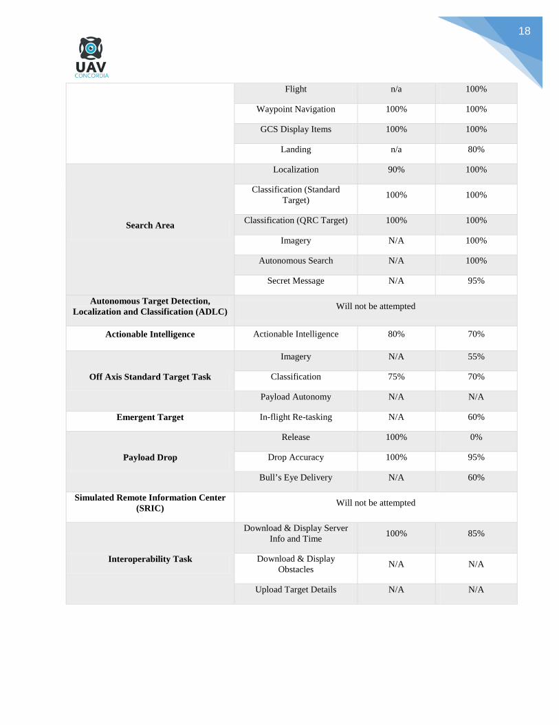
3.1. MISSION TASK PERFORMANCE
Mission Objective Subtask Threshold Achieved
Objective Achieved
Flight Time 66%(<20mins) 83.33% (< 30 min)
Autonomous Flight Takeoff n/a 90%
18
Flight n/a 100%
Waypoint Navigation 100% 100%
GCS Display Items 100% 100%
Landing n/a 80%
Search Area
Localization 90% 100%
Classification (Standard Target) 100% 100%
Classification (QRC Target) 100% 100%
Imagery N/A 100%
Autonomous Search N/A 100%
Secret Message N/A 95%
Autonomous Target Detection, Localization and Classification (ADLC) Will not be attempted
Actionable Intelligence Actionable Intelligence 80% 70%
Off Axis Standard Target Task
Imagery N/A 55%
Classification 75% 70%
Payload Autonomy N/A N/A
Emergent Target In-flight Re-tasking N/A 60%
Payload Drop
Release 100% 0%
Drop Accuracy 100% 95%
Bull’s Eye Delivery N/A 60%
Simulated Remote Information Center (SRIC) Will not be attempted
Interoperability Task
Download & Display Server Info and Time 100% 85%
Download & Display Obstacles N/A N/A
Upload Target Details N/A N/A

19
3.2. PAYLOAD SYSTEM PERFORMANCE
Several airflow simulations for the payload have been computed using Solidworks during the research stage of the
project. The main purpose of these simulations has been to determine the influence of the wind direction on the water
bottle payload. Results from the simulations have led the research team to the conclusion that the most efficient way
to reduce wind turbulence was to launch the water bottle in a vertical orientation rather than a horizontal one. The data
retrieved also helped the team in designing an optimal drop mechanism capable of accurate payload releases. Later
on, several tests on the test field have been performed to assess the reliability of the payload release mechanism.
Shown above are visual representations of the simulations computed:
Figure 9. Original UAV Platform Designed Figure 10. Actual Platform Frame Hub
3.3. AUTOPILOT SYSTEM PERFORMANCE
3.3.1. Waypoint Navigation
Navigation through each of the waypoints designated is ensured through the use of Mission Planner. The system has
been tested with the objective of reaching the desired waypoint accuracy specified in the competition terms.
3.3.2. Autonomous Search Area
One factor considered by our team to increase the efficiency of the area search was to increase the area coverage of
our system. This has led the team to consider two factors in the overall design of the system; imaging equipment with

20
optimal resolution and higher flying altitude. Those two implementations allow for a faster rate of coverage of the
search area, thereby allowing the team to accomplish several objectives such as ADLC faster.
4. SAFETY CONSIDERATIONS
Numerous test flights have been performed with the current platform during which the safety of the UAV was
evaluated. Our main focus has been to minimize the risk of any damage or injury from occurring.
4.1. SAFETY CRITERIA
Prior to the test flights, safety precautions have been taken to reduce the risks of any system malfunction. These safety
measures included:
• On-site safety inspection is performed to ensure all safety standards and requirements are met.
• Visual inspection of the structural components of the platform. The detection of visible flaws would lead to
the cancelling of the test flight in order to eliminate any chance of catastrophic mechanical failure during
flight.
• Inspection of all batteries used for any signs of damage and ensuring they are properly charged. Lithium-
polymer batteries impose a fire hazard if they are damaged or are not properly charged.
• Inspection and testing of release mechanisms for the payload systems.
4.2. SAFETY RISK MITIGATION
The risk mitigation methods developed by the team are listed in the table below:
Risk Factor Description Risk Level Impact Mitigation Method
Electrical Short-Circuit
An electrical short-circuit may potentially be a fire hazard for the
lithium-polymer batteries.
Low High
Short-circuit protection has been incorporated near the batteries, more specifically in the wire
harness connecting the battery to the power distribution PCB.
Two options are being considered: inline cartridge fuse holders or inline AGU style
thermal circuit breakers.

21
Driver Power Failure Medium Low The autopilot will bring the aircraft to land for
inspection.
Propulsion System
Malfunction (Motors)
A malfunction in one or more of the motors
compromising the flight stability of the
UAV.
Low High
Once the pilot realizes one or more motors are compromised he will put the thrust stick to off which will place the aircraft in free fall. Once the quad is close to the ground the pilot will
swiftly place the thrust to max and back to low giving it a softer landing.
Controller Battery Loss
A loss of connection to the controller may
cause unpredictable behavior of the UAV.
Medium High A built in function to land is to be
implemented if ever connection to the controller is lost.
4.3. DESIGN SAFETY CRITERIA
Prior to test flights, visual inspection was performed in order to detect flaws in any of the structural components of
the platform. As for the electrical systems, several components have been integrated in order to prevent critical
malfunctions. For instance, short-circuit protection has been integrated in the wire harness connecting the battery to
the power distribution PCB to reduce the fire hazard risk inherently associated with the Li-Po batteries.
5. CONCLUSIONS
This technical journal presents an overview of the efforts deployed by the students from the UAV Concordia team.
Throughout the last year, a great deal of learning was necessary for many of the team members in order to develop
the different systems present on our platform. The most significant tasks faced by our team included the integration
of autonomous target detection capabilities and the designing of a reliable payload drop mechanism. Safety has also
been a concern throughout the assembly and testing phases of this project as seen with the implementation of
various safety procedures. In all, the completion of all primary and secondary tasks has been our main objective and
this has guided our team’s dedication in completing the UAV.