u. s. navy rigid frame utility warehouse building · 2. frame: assemble and raise rigid fromes....
TRANSCRIPT
U. S. NAVY
RIGID FRAME UTILITY
WAREHOUSE BUILDING
ERECTIO.N INSTRUCTIONS FOR THE 40 '·0" x 100'·0" BUILDING
NAVY DEPARTM ENT BUREAU OF YARDS AN D DOCKS
BUTLER M FG. CO. GALESBURG KANSAS CITY MINNEAPOLIS

-.
,
U. S. NAV Y
RIGID FRAME UTILITY WAREHOUSE BUILDING
* ERECTION INSTRUCTIO N S
FOR THE
4 0 '·0 " x 10 0'·0" BU ILDING
* MANUFACTURED FOR
NAVY DEPARTMENT BY
8UTLER.*MfG. CO. GALfSBURG KANSAS CITY MINNEAPOUS
U. S. A.

ERECTION SEQUENCE BASIS UNIT
1a. Foundation: Set forms, pour concrete, set anchor bolts. lay bose shoes and bottom angles...... .. _____ .. ...... ___ ...... ........'.... ......... ........ ..... .____ ...... 3
1b. Jig set· up and Field Welding: Use one end frome for iig. Weld haunch and column . ... .. ........ _. __ .... ....... __ ........ .... __ ... __ .. ............ .... ___ ........... __ 6-9
2. Frame: Assemble and raise rigid fromes. Install eave struts, purlins, girts and diagonal bracing...... ... .. ... .... .... ...... ... _......... ..... .... .. . ...._.........__ .... .____ ..__ .__._ lO ~ 15
3. End Framing. Assemble end framing using channel door posts, header and girts..... ... __ .. ..... .. .__ .. ........ ...... ....... ___ ... ...... .... ... ..... .... .__.... ...... .. ... ......16-17
4. End Covering, Doors and Windows: Apply Butler corrugated sheets, louvre, hang doors, assemble and install windows...... .. .... ....._..... ._....... ... ........ .. .18-23
5. Covering: Bolt Butler corrugated shee ts on sides and roof of the building, field punching the flat between corrugations to hold sheets to grits and purlins .24-25
6. Suggestions to Erector..... ... ..... .._..... ........... ........... ...... ... ...... .. ... '.'. ". __ .. .... ... .. .. 26-27
7. Adoptions . .. .. ..... ........... ..... ................ ..... ...... ... .... .. ...... ........... .... ........ .. .. .. .28
8. Clean up: Save all extra pieces, bolts, washers and crating material not used . Sort and store for future use.
Erection Drawings Applying to Navy Utility Building (See Pocket ;n Bade Covel)
End Elevation ........... .... _ ..J -BE-2623-1
.Side Elevation and Roof Plan... ... _.. ..... ... ... .._... ............... .. ...... .. .... ......_ .7-BE-2623-2
Multiple Building Unit ... .... ....... .... . .. .. .......... .................... .... .. .. ............. .. .. ...J-BE-2623-3
Rigid Frome .......... ._._.. .__ ........ ." ... ... _... .........7-BE-2623·4
Foundation Plan (Single)_....... ._...._.... . .. ... .... .. ....... ...... ... .7-BF-2623-1
Foundation Plan (Multiple).. ...........J -BF·2623-2
list of Material .. .. .. .... ..... ... ..2-BM-2623-1, 2, 3, end 4
Schedule of CrateL .. ....... ._... J-K-4
2

-BASIC UNIT THE FOUNDATION Drawing No. 7 -BF-2623- J
Place forms for concrete, pour the concrete being sure to keep foundation square and level. If steel reinforcement and floor expansion joints are required due to local cond itions place as desired by person in charge of foundation construction.
1. Place the !" round by 8" long anchor bolts (fo r columns) and !" round by 411 long qnchor bolts (for base angle) accurately (per foundation drawing No. 7-BF-2623-1). Do this
by mea su ring along form and using these points on the forms a s center line of the anchor bolts.
Chalk line has been furn ished to line up bolts along wall.
2. The Floor: Slob is the some level as the fou ndation and con be poured in four longitudinal strips approximately la ' wide or it may be poured one bay at a time making five 20' slabs.
NOTE: Refer to section describing jig set-up and field welding as this work can be done while the foundation is being prepared.
3. lay the corner base shoes marked BP-2 and interm ediate base shoes marked BP-l
which are punched to fit over the bolts at each column. The n lay the bottom angles which are punched to fit over the bolts between columns placing the angles marked BA-3 on end walls,
BA-2 and BA-2R in the end bay along sidewall and angles marked BA-l in all intermediate
bays along sidewalls. leave these angles loose until sheeting has been placed to allow for
necessary adjustment.
3
BASIC UNIT THE FRAME (GENERAL)
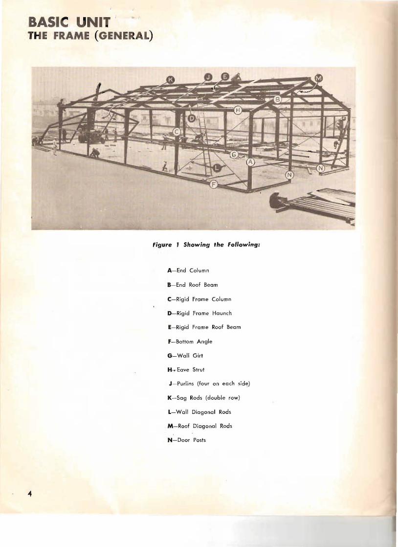
Figure I Showing the Following:
A- End Column
B- End Roof Beam
C-Rigid Frome Column
D-Rigid Frame Haunch
E- Rigid Frome Roof Beam
F-Bottom Angle
G-Woll Girl
H~Eave Strut
J - Purlins (four on each sid~)
K-Sog Rods (double row)
L-Wall Diagonal Rods
M-Roof Diagonal Rods
N-Door Posts

The building frame consists of two end and four intermediate rigid frames for a 100' long building. The end rigid frames are assembled from four sections and the intermediate rigid frames are assembled from six sections. It was decided to field weld the connection between the haunch and the column of the intermed iate rigid frame due to the shipping and handling problems of the joined sections. As described later the end rigid frame is assembled and used as a welding jig. These frames a re spaced on 20' centers and are bolted to base plate shoes at the bottom. These frames are connected by two wall girts, two eave struts and eight roof purlins.
The end boys only receive a series of diagonal rod bracing in each sidewall and in the plane of the roof. These rods are installed after the first end frame and the first intermediate rigid frame are in place and are used to square and plumb the building. It will be necessary to obtain from the crating, ti mbers to use as gin poles for the erect ion of the first end truss. After this truss is erected all remaining trusses will be erected by attaching the two erection pulleys to the last raised truss using pulleys to pull truss into vertical position.
Two sizes of bol1s only are furnish ed for the erection of the frame. The iff x H" machine bol ts are used only at the base and splice connections of the rigid frame. The 1" xl" machine bolts are used on all other connections.
5

0 :CIIB Q,. enCIt
m n -jIC: C: "' » z Z-I c ." ,-m I"'" C
~ rn I"'" C-Z Q
Assemble one ot the end trusses os detailed above. Before using jig, check distance across the bottom against distance across eaves, thus making sure columns are parallel. This will properly space the base of the columns so that all rigid homes will fit toundation ofter being welded.
Figure 2

Detail A: At the eave point the end column marked C·l bolts to the end roof beam marked RB-2 with twa splice plates marked SP- l (one on each side of the web) and with one corner bracket marked CB bolted to the inside flange.
~ -I\' --.,.
-
_ G .. . : RS- ;t ~ RP~.3 . ' . ' ___f"'::~ .,C
.- . ..~,- - S -- ..~. "~-::;, --. ... O .~ RP'Z-'~ I,
~•f
-~
Detail B: At the ridge of the building the two e nd roof beams marked RB·2 bolt togethe r using two plates marked RP-3 (one on each side af the web), one bent plate marked RP-l on the top flang e and one bracket marked RP-2 on the bottom flange.
Detail D: Bolt gid, morked DG·l ond DG·l R (with open channel toward ridge) in place using cl ips marked CA·l and CA-l R for connection to column.
DP-I
Detair E: Use clips marked CA-6 for connection ot girts !o door posts.
bp
Cp,,-7
l,.. ,,
- I
.... I:'
Detair C: Next bolt door posts marked DP-l and DP-l R in place, using clips marked CA-5 and Detail F: Assemble door header marked DH-l CA-5R for connection to roof beam. between door posts using clip marked CA-7.
7

FJ - ' -_
figure 3
Bolt rigid frame column marked
RF- l and rigid frame haunch
marked RF-2 to the jig clips having
1he diagonal cuts of the two members butted together.
Attach ten iig clips marked FJ-l
to truss allowing clips to extend
above truss thus completing the iig.
f igur e 4
Tack weld together in three or
four places and then continuously
weld web and lower flange and
inside of top flange.
figure 5
6

Weld one angle reintorcemenf marked SPA-lover this joint before removing from jia . Note this reinforcement angle is notched at one end to closely fit the lower flange and this should be continuously welded.
figure 6
Remove this assembly trom the jig, turn over and while laying flat on the ground weld the other side of the flanges so the flanges are welded continuously. It is not necessary to weld opposite side of the web. Place another reinforcement angle marked SPA-lover this joint again making sure the lower end of the reinforcement angle is welded continuously to the lower flange.
Suggestion: This some procedure can be followed using the other side at the jrg, allowing two welders to work simultaneously. Proceed likewise for remaining haunches.
Welding rod has been furnished for each building and it has been estimated On overage at
eleven rods shall be used for each haunch welded. It is assumed DC welding machines are
available in the field. The rod is for this type machine.
Touch-up paint and brush has been furnished with each building for pointing this welded connection to complete it.
While the welding is progressing, another crew can proceed with the erection af the
building by assembling the other end truss and using welded haunch members as they become
available.
9
BASIC UNIT ' ASSEMBLY AND ERECTION Drawing Nos. 7 ·8E-2623- J, 2, and 4
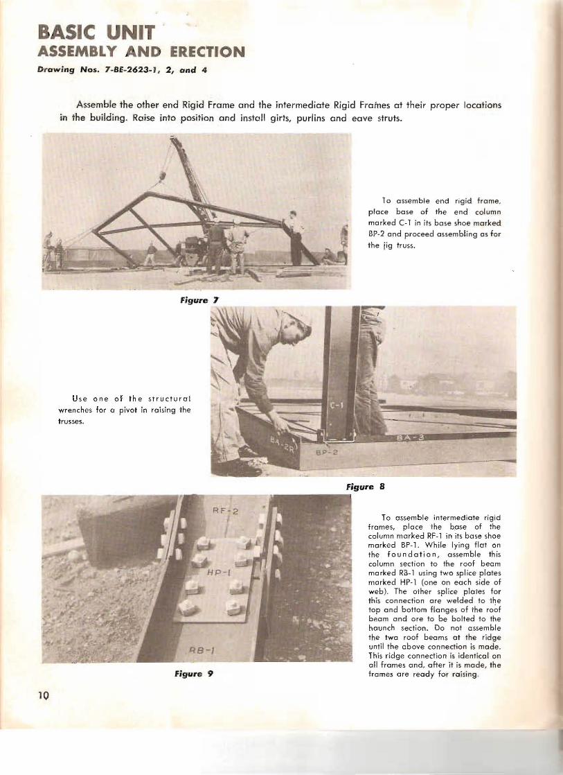
Assemble the other end Rigid Frame and the intermediate Rigid Fralnes at their proper locations in the building. Raise into position and install girts. purlins and eave struts.
figure 7
10 a ssemble end rigid frame,
place base of the end column marked (·1 in its base shoe marked Bp·2 and proceed assembling as for
the iig truss.
Use one of the structural
wrenches for a pivot in raising the
trusses.
figure B
figure 9
To assemble intermediate rigid frames, place the b.ose of the column marked RF-l in its base shoe marked BP-l. While lying flat on the foundation , assemble this column section to the roof beam marked R3-1 us.ing two splice plates marked HP-l (one on each side of web). The other splice plates for this connection are welded to the top and bottom flanges of the ro~f beam and ore to be bolted to the haunch section. Do not assemble the twa roof beams at the ridge until the above connection is mode. This ridge connection is identical on all fromes and, ofter it is made, the f.rames are ready for raising"
10
~ ~ I
~-----"
./
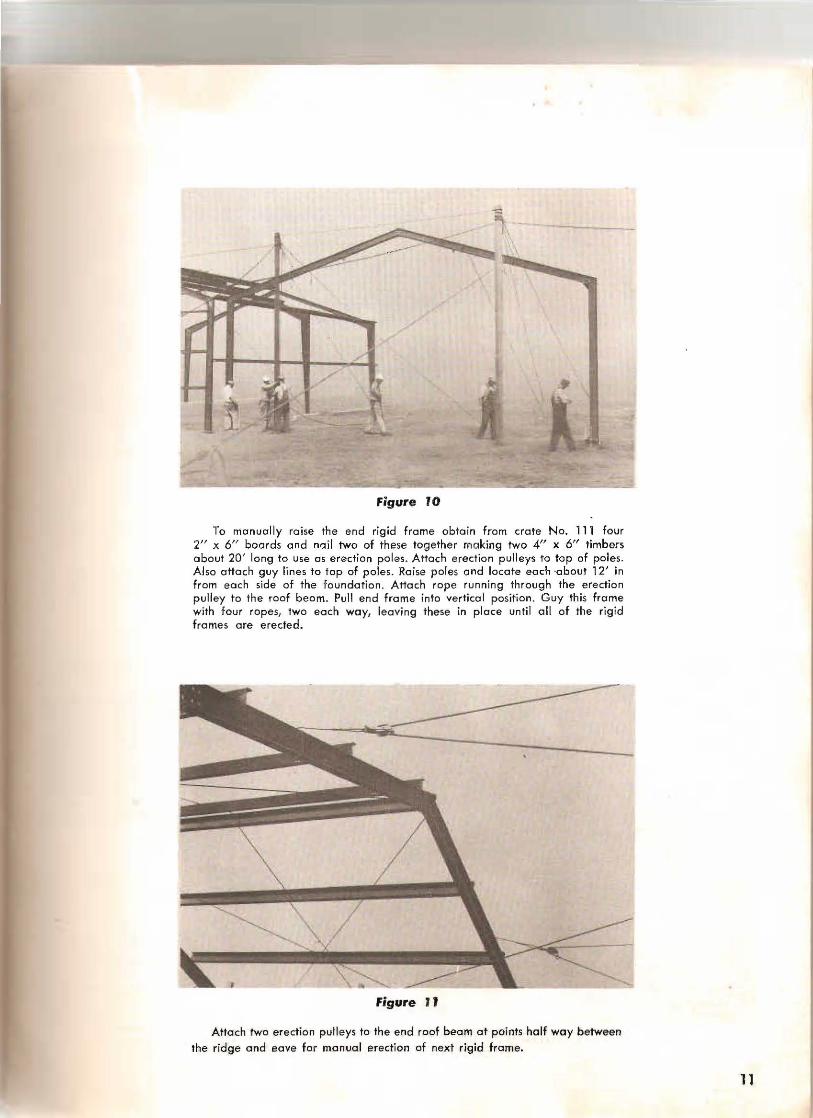
figure 10
To manually raise the end rigid frame obta in from crate No. 111 four 2" x 6" boards and nail two of these together making two 4" x 6" timbers about 20 ' long to use as erection pol es. Attach e rection pulleys to top of poles. Al so attach guy lines to top of poles. Raise poles and locate each -about 12' in from ea ch side of the foundati o n. Attach rope running through the erection pulley to the roof beam. Pull end from e into ve rtical position. Guy this frame with four ropes, two each way, lea vi ng these in place until all of the rigid frames are erected.
figure II
Attach two erection pull eys to the end roof beam at points half way between
the ridge and eave for manual erection of next rigid frame.
11
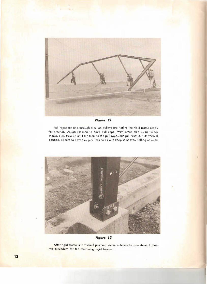
Figure 12
Pull ropes running throug h e re ction pulleys ore tied to the rigid frame reody
for erection. As sign six men to each pull rope. With othe r men using timber
shores, push truss up unti l the men on the pull ropes can pull truss into its vertical
position . Be sure to have twa guy lines on truss to keep sa me from foiling on over.
Figure 13
After rigid trame is in vertical position, secure columns to base shoes. Follow this p rocedure for the remaining rigid frames.
12

~
A Detail A-Figure 14
figure 14
Detail A-Figure J5
figure 15
After the end and the first intermediate rigid frames have been erected attach the eight
purl ins marked P-l (Detail A), the two eave struts (each being made up from two members marked E-l bolted bock to back [Deta il B]) and the two girts marked G-l. Notice that wall
girt is made of thicker steel than roof purlins. They are the some size otherwise and although they are plainly shop marked it is possible to use one in place of the other. The design specifica tions require thot the- heavie r one (marked G-l ) be used in the wall.
13
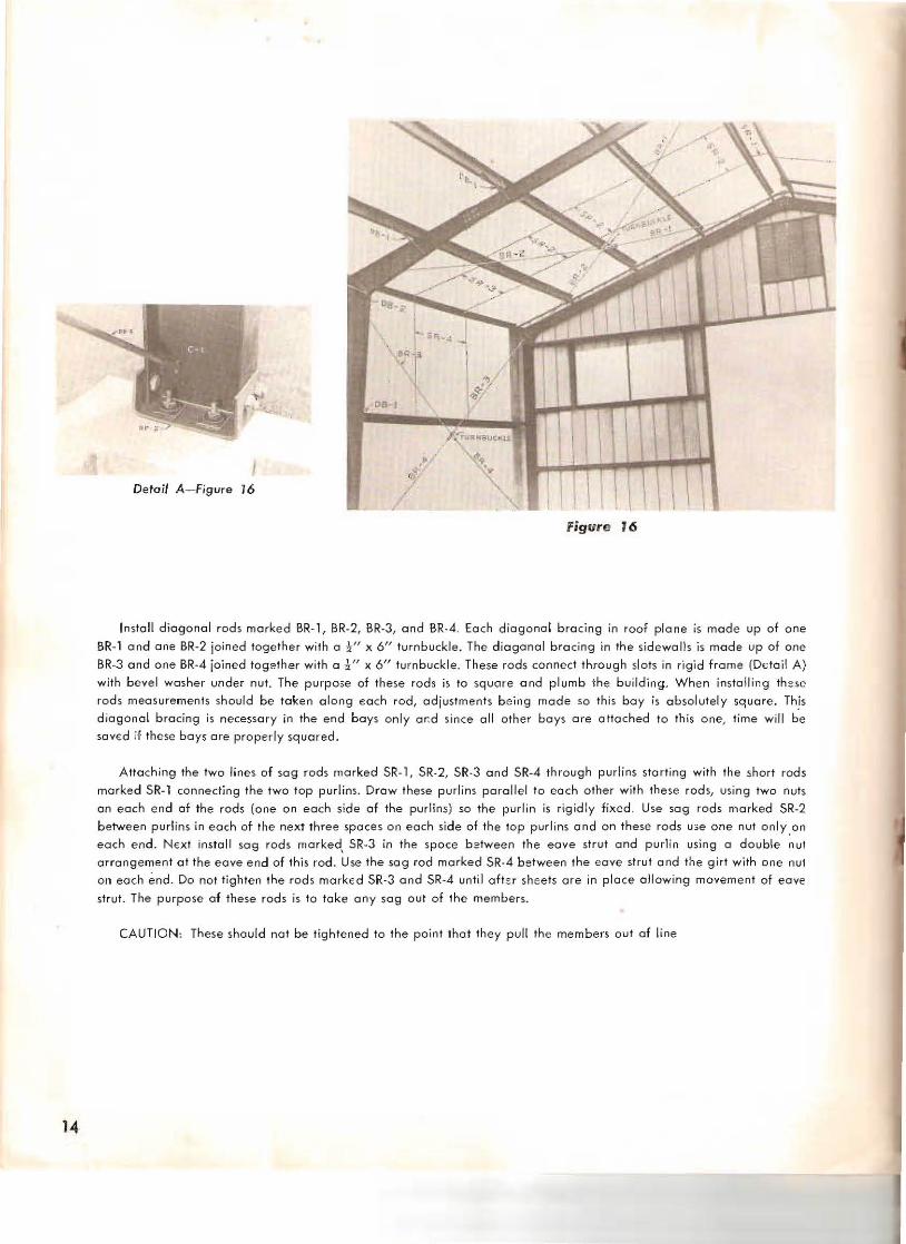
Detail A-Figure 16
Fig ure 16
In~tall diagonal rod~ marked BR-T, BR·2, BR·3, and BR·4. Each dia gonal bracing in roof plane is mode up of one
SR-1 and one BR-2 joined together with a i " x 6" turnbuckle. The diagonal bracing in the sidewalJ~ is mode up of one BR-3 and one SR-4 ioined together with a i ff x 6" turnbuckle. These rods connect throug h slots in rigi d frame (Detail A)
with bevel washer under nut. The purpose of these rods is to square and plumb the building. When installi r.g th ese
rods measurements should be token along each rod, adjustments b8ing made so this bay i~ absolutely square. Th!s diagonal bracing is necessary in the end boys only ar:d ~in ce all other boys are attached to this one, time will be saved if these bays are properly squared .
Attaching the two lines of sag rods marked SR·l , SR-2, SR·3 and SR-4 through purlins starting with the short rods
marked SR-l connecting the two top purl ins. Draw these purli ns parallel to each other with these rods, using two nuts
on each end of the rods (one on each side of the purlins) so the purlin is rigidly fixed. U~e sag rods marked SR-2 between purlins in each of the next three spaces on each side of the top purl ins and on these rods use one nut only.on
each end. Next install sag rods marked, SR-3 in the spoce b3tween the eave strut and purlin usi ng a double nut arrang ement at the eave end of this rod. Use the sag rod marked SR-4 between the eave strut and tne girt with one nut on ea ch end. Do not tighte n the rods marked SR-3 and SR-4 until after sheets are in pl ace allowing movem ent of eave
strut. The purpose of these rods is to toke any sag out of the members.
CAUTION: These should not be tightened to the point thot th ey pull the members out af line
14

figure 17
At any time after two or more boys o f the structural framework are erected, install the diagonal braces marked
08 -1 and D8-2. The DB-1 membErs ore used o n the first two rows of purl ins above the ea ve and on the girts. The D8-2
members connect to the eave struts having a notched end to allow it to be baited between the strut. These braces ore
notched to fit around the inside flan ge of the rigid frame beams and to install lay this notched portion flat against the
frame f lange and bend the brace to bolt in pla ce. Becau se of th e column taper and for interchange ability two ho[ e~
ore provided in the purl ins and girls, use the holes which will make this member toul
NOTE: No brace is to be used in the upper four rows of purlins
15
BASIC UNIT THE END FRAMING Drawing No. 7-BE-2623-1
Attach the end framing, including girts and louvre angles to the end rigid frame using angle clips. This is assuming the door posts marked DP-1 and DP-1 R, the girts marked DG-1 and DG-1 R, also door header marked DH·1, were bolted in place as described in the "basic unit" under the section "J ig Set-Up and Field Welding," before the end truss was raised.
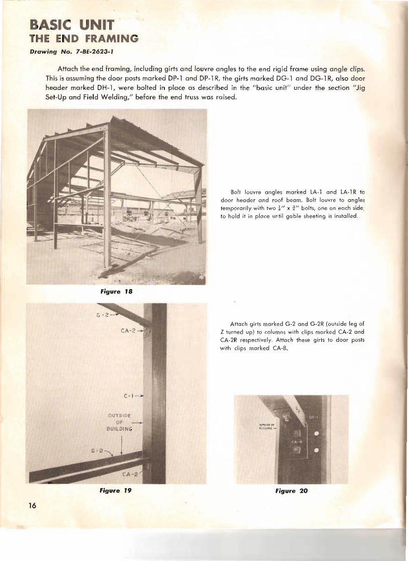
. , figure 18
(- 1-
OU1 5 10 E or _
BUIL DIN G
figure 19
Bolt louvre angles marked lA·l and lA-l R to
door header and roof beam. Bolt louvre to angles
temporarily with two ~ If X t " bolts, one on each side,
to hold it in place until gable sheeting is installed .
Attach girts marked G -2 and G-2R (outside leg of Z turned up) to columns wi th clips marked CA-2 and
CA·2R respective ly. Attach these girts 10 door posts
with clips marked (A-B.
figure 20
16

figure 21
b ~I
\
)
The window a ng les marked So l a nd S-l R connect to the girts with clips morhd (A-3. The window angles marked CW-l and CW-1R
bolt bo ck to bock and connec t to girts with four
clips (two o n each e nd) marke d CA-4.
CWo) }CW - I!'. /
5- 1
OUTSID[ OF BUILDING
figure 22
17

BASIC UNIT THE END COVERING INSTALLING DOORS AND WINDOWS Drawing No. 7-BE-2623-1
Apply sheeling, assemble Ihe doors and inslall. Assemble windows and inslall.
This buildin.9 is covered with
BUTlER corrugated sheets having a deep drawn corrugation 12/1 on center.
These corrugations are factory
punched approximately 2 ' on centers, also factory punched for end
connections.
figure 23
It is only necessary to field punch the
holes in the flat of the sheets to secure sheets to girts and purlins. Holes in girts and purlins
ore factory punched and by using the
i" x 9" x iff punch that is furnished the holes may be easily punched in the sheets
to match the holes in these member~. On the end woll th ese holes o re to be punched
after the end sheeting is completely installed.
figure 24
The top sheet should lop oYer the bottom sheet at all times to obtain a weo thertight connection in all sheeting and raofing. The end wall sheeting should be started at some pe rmanent point such as corner or door posts or building center line, so sheets can be kept straight and plumb throughout the entire end wall.
Since 011 end and side laps of sheets a re pre-punched, a certain amount of adjacent sheet ing can be bolted together as a sub-assembly and erected as 0 g roup on the end wall .
figure 25
Sub-assemble the corner sheet group using the following sheet" e5·' R, e5·2R, W·' , GW·' R, we-" ond We·2. These six sheets when a ssembled will form the corner sheet group for the right hand end corner. Use sheets marked similar but with the exception of the URN for the left hand end corner group. Attach these groups of sheets to their respective corners bolting them to th e bottom angle first and then eave strut.
18
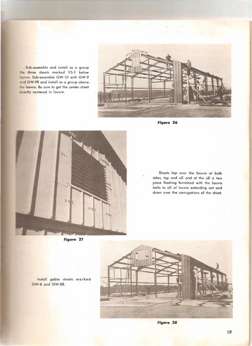
Sub-a ssemble and install as a group " 'I : three sheets marked YS- l below ·"JtJYTe . Sub-assemble GW-10 with GW-9 ...; .,d GW-9R and install os a group above . "'"Qe louvre. Be sure to get the center sheet ~.xn ctly centered in louvre.
Figure 26
Figure 27
Instal l gable sheets ma rk e d
GW-B and GW-BR.
Sheets lop over the louvre a t both sides, top a nd sill a nd at the si ll a two piece flashi ng furnished with the louvre bolts to sill of louvre extending out and down over the corruga tions of the sheet.
Figure 28
19

Bolt side louvre sheets marked SV-l and SV-1R in place. Also sub-assemble
the six gable sheets marked GW-2Rr GW-3R, GW-4R, GW-5R, GW-6R and GW-7R, attaching gable angles marked GA-l and GA-2R to the top of these
sheets haVing the top leg of the angle turned out, as the roof sheets bolt to this
leg. Raise info place 05 a unit. Sheets on
the left side of gable are marked similar
except without the " R.1f
While this work is progress ing the five
sheets marked W-1W con be assembled as a unit and installed under windows.
figure 20
80lt sheets marked SW· 1 and SW-2R in place at each side of the window
openings being sure to slip the top of this
sheet under the gable sheets. Also bolt the side door sheets marked 5D-1 Rand
SD-2R in place_
NOTE: These .sheets may be installed
before the gable sheets if desired.
figure 30
Door Assembly: To reduce cUbage the door sheets and the door fram e have been shipped knocked down. For assembling the left hond door, layout the side angles marked DA-' and DA-2R, olso the top ond bottom angles marked DA·3. These angles should be placed with the outside leg turned up so door sheets will loy inside. lay the corner brace plates DCP-l in place but do not bolt . Attach the side door shee ts marked DS-12E to their respective door angles, then attach door sheets marked D5-12 to fill the doo rs. All door sheets and angles are factory punched to make this much of the assembly. All bolts should be left loose until the door has been checked to make sure it is square. After this check is made bolts should be tightened.
Field punch holes through the sheets for the ~" x 1" bolts to hold the corner plates and the girts marked DA-4 in place. This will keep the sheets from bulging over the bolt head.
The girts marked DA-4 bolt to the inside of door. When in place punch holes in sheets in the flat between corrugations to match girt punching and bolt with stove bolts. Attach the bow type handle to the DA-~R by punching holes through the shee t. Attoch the door roll e rs to top frame angle of door.
figure 31
20

Door Erection: These doors are inside ;: ~ type. Place two track brackets on
;r-e- p iece of track and bolt these to the .:. -:.at header so this track is centered in 7 ?en~n9. Bolt the other two pieces of
'-=: : k in place using a bracket at the -:: .:te and two other brackets on each
- ~ ;e. Do not bolt the two end brackets - ::;, o::::e until after doors have been hung.
Figure 32
Hang doors and bolt the two end track brackets in place. Adiust doors for level by the top rollers. Close the doors and loca te the center door stops. Star drill hol es a nd secure to the concrete with il! expansion shields and screws. With doors in closed position locate the door guide shoe at each jamb so the doors will be held firmly against jambs. Star drill holes and secure guides to concrete with i " expansion shields.
Bolt door header tlashlng markea DF-l to slotted holes in door header and bolt the side door flashing marked DF-2 to slotted holes in door posts. Use t" )( iN slove bolts
DF-2
Figure 33
21
'It... " 15 .2'...

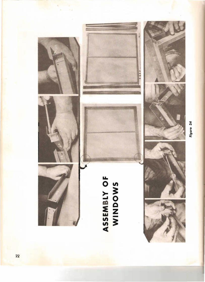
Figure 35
Afte r outside fra me is a ssembled, window is inserte d a nd hinges a t~
tached wi th se lf topping screws as
indica ted.
Stay bar is a ttached, on inside :! window unit, to clip nea r bottom :: T" vertical center bar wi th mac hine :": rews a s illustra te d.
Figure 36
Figure 37
INSTA LLATI ON O F W IN DOWS,
Place the window sa sh in ope ning having to p of window be hind wo ll shee ts
above window, and outside of side win~
dow sheets. Place the 2 type fl ashing under sill of wi ndow so it will exte nd out and down over the top of corrugations. Place sheet marked SW·3 betwee n win· dows a t time of window insfal lotion .
23
BASIC UNIT THE SIDEWALL A ND ROOF COVERING Drawing No. 7 -BE-2623-2
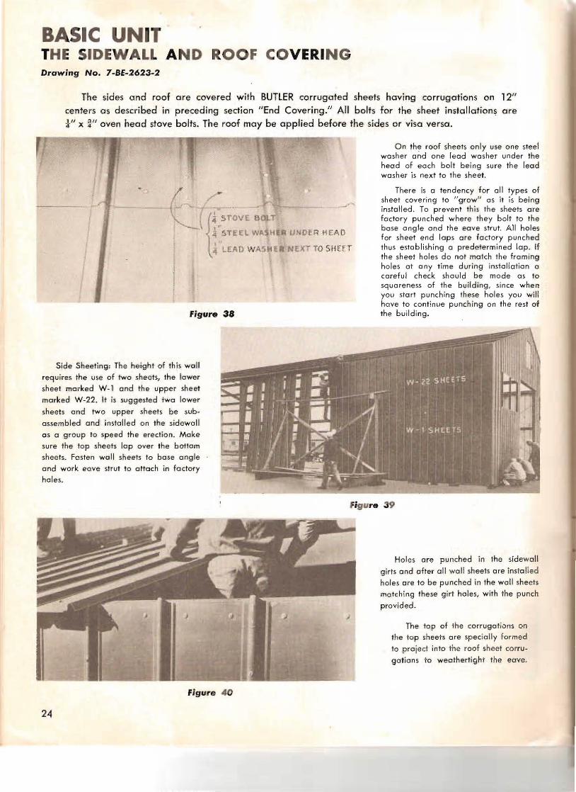
The sides and roof are covered with BUTlER corrugated sheets having corrugations on 12" centers as described in preceding section "End Covering." All bolts for the sheet installation~ are i" x !}" oven head stove bolts. The roof may be applied before the sides or visa versa.
On th~ roof sheets only use one steel washer and one lead washer under the head of e ach bolt being sure the lead washer is next to the sheet.
There is a tendency for all types of sheet covering to I/growil as it is being install ed. To prevent thi s the sheets are factory punched where they bolt to the base angle and the eave stru t. All holes
(({'r:'srOVE Elon ~ "TELL WA~H • IlNOe R HE AD for sheet e nd laps ore factory punched
, .j LEAD WASttEII NEXT TO SHEfT thus establishing a predetermined lop. If the sheet holes do not match the framing holes at any time during installation a careful check should be mode as to squoreness of the building, since when YOll start punching these hole s YO ll will have to contimJe punching on the rest of
figure 38 the building.
Side Sheeting; The height of this wall requires the use of two sheets, the lower
shee t marked W-l and the upper sheet marked W-22. It is suggested jwa lower
sheets and two upper sheets be sub
assembled and installed on the sidewall
05 a group to speed the erection. Make sure the top sheets lap over the bottom sheets. Fasten wall sheets to base angle and work eave strut to attach in factory
holes.
f igure 39
figure . 0
Holes are pu nched in the sidewall
girts and after all wall sheets are installed holes are to be punched in the wall sheets
matching these girt hales, with the punch
provided.
The top of the corrugations on the to p sheets are specially formed
to project into the roof sheet corru
gation s to weothertight the eave.
24

:.~-: Sheeting: Use lead and steel ~ !"'! ~ i all bolts in the roof. Be sure - :- .~ :op sheet over the bottom sheet.
'=. • _.., mastic with gun is furnished
· jzontal end laps of roof sheets. -Olmol weather conditions this
- eed nof be used elsewhere. Apply ~. :: fo lower roof sheet (R-22 ) being ~ ' =, ~eep bead of mastic below fac
:l'.... - , hed holes in flat of sheet be:c rrugations.
Fir/ure 42
ne roof sheets may also be sub=ue.-nbled into groups of two or more ,..= assembled as a group on the roof.
er. applying roof sheets, in order to -,.event the above explained tendency to ;row" it is suggested that as eoch com=-~fE run of roof sheets is insta lled that - e1 be bolted to purlins making sure the =e-s which are punched in the sheets, to
- ct-ch the factory punched purlin, is H :J:::Hy in the center of the roof sheet be". ~n corrugations. Proceed the length
-=- ~ ·"e building keeping sheets straight.
Flr/vre 41
The top sheets marked R-l1 have one end curved a nd to form the ridge of the building th e curved ends of the ridge sheets are bolted together. The lower or eave sheets marked R~22 have one end punched for the splice connection to the ridge sheet and the other end is punched between corrugations to bolt to the eove strut: This completes one run of sheets over the building. Bolt this one run of sheets to the eave strut centering it over the end truss and field punch holes in these roof sheets to attach them to the gable angle. Be sure to keep the gable angle parallel with the line of corrugations.
NOTE: Be sure first row at sheets ' is started square with the bUilding. :
Figure 43
25
BASIC UNIT SUGGESTIONS TO ERECTOR
This erection procedure as a whole is based on field conditions where all erection must be handled by manual lobor. If mobile equipment is available the erection con be followed olong the same general procedure but would be speeded considerably. A mobile crane with a boom about 20' long would speedily erect the rigid frames.
fOI your help approximate weights 01 the following component parts ore:
One end frome less the wall framing, approximately..... __ .. .... ... __..__ ......... __ ... l1 00 Ibs.
One intermediate rigid frame, approximately.._____ ...______.. ______ .. .. ______... ____ .. ... __ 1200 Ibs.
One purlin, approximately ..... _... __... _ ... _____........ ... ______.. ___.. _ .. _ ....... ...... ___.....__ .. 65 Ibs_
One girt, approximately ....... _________ .__ __ ....____.. _ .. ______ ..__ ___ __ _._______ ...____..______.. _____ 130 Ibs.
One assembled eave strut, approximately..__ ___ _._______ . ________. ______ ._______ .. . _______ _._ 130 lbs.
One wall sheet, approximately___ _.___ _____ ___. ________ _____ . ________._______._______ ________ ._______ 25 Ibs.
The ease of erection and alignment of this building is based on getting the end truss correctly assembled since this is used as a iig for welding the intermediate rigid frames.
Organization: While one crew is welding the rigid frames together, another crew can be laying out the foundation. If the foundation has been previously made this crew can be assembling the other end truss and proceeding with the erection of the building. As soon as the first end bay is erected and properly squared with the diagonal rod bracing, another crew can assemble and erect the complete end wall. Much sub-assembly can be carried an while the erection of certain parts is being done.
2(i

... l.":.eeting cre w consists of two men, -~ equipped with a Yankee screw
...-=:- and a lining-up punch . This man on the outside of the building.
-.-~ ~'o.nd man will work on the inside - e btlHding opposite his portne r. The ., ::;d nuts sholl be separated giving
.. -~s fo the man on t" e inside of the :.... ~4" g and t"e bolts to his portne r. To ~ gp this work a t.,ird man con keep --=. ~~ -eet i ng cre ws busy by obtaining and -=.- ....3 out sheets for each crew.
figure 44
Core should be token not to teor or re punch any factory punched sheet holes. If these do not line up wit" factory punched framing holes a check should be made on the alignme nt of the building.
There is 0 knack in breaking the me tal band on crotes that if used will save time and tempers. Insert a screwdriver under bond and turn blade so that shorp side of blade will contact ba nd and then pull screwdriver up quickl y. T.,;s will break band easily.
Tools: A list of the tools furnish ed is in ,"ematerial list. Three complete sets are furnished for eve ry five buildings and if a group of buildings are to be erected ot one location these
tools can be pooled for more conve nie nce .
SCAFFOlDING,
This shows one type of scaffold· ing used to apply roof. This is simple and may be constructed from t"e crating lumber.
Figure 45
'27
BASIC UNIT ADAPTIONS
BUildings set side by side: If desired to obtain more working area under one roof, these Butler rigid frame buildings can be set side by side. The adjacent sidewall sheets and girts need not be used giving a dear opening between buildings. It is recom mende d, in order to obtain" necessary gutter area joining the roofs of these buildings, the buildings be spaced apart 2' 1"
back to bock of adjacent columns. Core should be taken to keep this measurement-exact and for foundation pion for buildings when they are so set refer to drawing No. 7-BF-2623. This
drawing will give you information for the foundation for any number of buildings set side by side.
It will be ne<:essory to make the gutter between th ese bUildings in the field . For this we recommend the use of the sidewall sheets marked W-l. FlaHe n the two outside corrugations of these sheets and bend as shown on the upper left hand corner of drawing No. 7-BE-2623.1.
When installing use the sa me bolts as those that join the eave sheet to the eave strut. This gUHer should slope approximately i" every eight feet from the center of the bUilding out
toward each end wall. lap ends of guHer at least 6" uSing lead and steel washers on bolts to hold guner together. Also use a sufficient quantity of mastic to properly seal gutter.
To close in the 2 ' 1" space on the end wall -between columns cut and fit wall sheets around gutter thus tying the two buildings together and completely we~thering the ioint.
Buildings set end to end: Although plans are based on the erection of a 100' long building. these buildings may be erected in lengths of any multip le of 20". If buildings longer than 100'
are desired it is recommended you use the end rigid frame in its regular position but when so
used the end wall framing such as door posts, girts, etc., must remain in place a s this end frame is not designed to corry an intermediate load such as the other rigid frames can carry. If a 40' clear opening must be had between bays of this longer building it is recommended to use one of the standard intermediate rigid frames.
Buildings on timber foundation: When buildings are intended for temporary use and a concrete foundation is not to be used. this type building may be erected on a timber foundation .
In this case it is recommend ed that a timber which has been trimmed to give one flat surface be used for the foundation wall.
For the base of all columns we recommend that a timber about 8" in diameter be set into the ground vertically with the top , level with the foundation wall. This timber should set into the ground at least 4' . Under des ign load there is approximately 3500 pounds outward thrust
at each base of the rigid frame and ta prevent movement at this point we recommend thot heavy stakes be provided in additial'1 to the vertical ,imber. lag screws should be used to secure
the building col umns and the building base angle to this type foundation.
The concrete foundation plan shown in drawing No. 7-BF-2623-1 can be used for general over-all dimensions of this type foundation.
Partitions: The standard end wall as shown on drawing No. 7-BE-2623-1 can be readily
used, with slight alteration, as partitions. This partition can be located at any desired position between rigid frames . It will be neces~ory to install the 'standard gable angles directly beneath
the purlins. It will olso be necessary to notch the end wall sheeting around the purlins and girts All other ports of the end wall con be erected as described heretofore.
The inh erent strength of the Butl er Rigid Frame construction makes it possible to hang a concentrated load at any de.. ired point an on intermediote rigid frame. Where normal wind and live loads may be expected a concentrated load of not over 4000 pounds can be suspended
from rigid frame.
28
