u gbav en - solé diesel · attempt to remove the cooler cap. read the genset operator's...
TRANSCRIPT

U_GBAV_EN
Rev. 6

INTRODUCCION
2
Operator’s Manual Marine Diesel Gensets
Revision 6. 08/2018

INTRODUCTION
3 Operator’s Manual Marine Diesel Gensets
Revision 6. 08/2018
INTRODUCTION
Presentation
Dear Customer,
First, we would like to thank you for choosing a Solé Diesel product. We recommend that
you read this manual carefully before carrying out any of the operations and keep it close at
hand, near the genset, as it can be of great use in the future.
Our goal as a manufacturing company is that you enjoy our product, regardless of the
use you make of it. The equipment manufactured in Solé Diesel facilities is designed to offer the
highest performance in the most demanding operating conditions.
The images, text and information contained in this manual are based on the product’s
features at the time of publication. Solé Diesel reserves the right to modify this document without
prior notice
Abbreviations
BTDC: Before Top Dead Center
ATDC: After Top Dead Center
BBDC: Before Bottom Dead Center
ABDC: After Bottom Dead Center
API: American Petroleum Institute
ACEA: European Automobile Manufacturers’ Association
ASTM: American Society for Testing Materials
TBD: To Be Determined
Units of measurement
Measurements are based on the International System of Units (SI), and their converted
metric values are indicated in parentheses (). For metric conversion, the following rates are used
- Pressure: 1 Pa = 1,0197 · 10-5 kgf/cm2 = 1 · 10-5 bar
- Torque: 1 Nm = 0,10197 kgf·m
- Force: 1 N = 0,10197 kgf
- Power: 1 W = 1,341 · 10-3 HP
TABLE OF CONTENTS
4
Operator’s Manual Marine Diesel Gensets
Revision 6. 08/2018
TABLE OF CONTENTS
INTRODUCTION................................................................................................................................................... 1
TABLE OF CONTENTS .......................................................................................................................................... 4
SAFETY PRECAUTIONS AND INSTRUCTIONS .................................................................................................... 6
SOLÉ DIESEL WARRANTY .................................................................................................................................... 9
SECTION 1 - Genset Information ................................................................................................................... 12
1.1. Genset Identification .................................................................................................................... 12 1.2. Genset Parts Identification .......................................................................................................... 13
SECTION 2 - Transport, Handling and Storage ............................................................................................ 15
2.1. Reception ....................................................................................................................................... 15 2.2. Transporting and Handling the Packed Genset ...................................................................... 15 2.3. Transporting and Handling the Unpacked Genset ................................................................ 16 2.4. Storage of Packed and Unpacked Genset ............................................................................. 16
SECTION 3 – Installation .................................................................................................................................. 17
3.1. Angle of Installation ...................................................................................................................... 17 3.2. Genset installation ........................................................................................................................ 17
SECTION 4 - Operation.................................................................................................................................... 18
4.1. Prestart Checklist ........................................................................................................................... 18 4.2. Genset Operation at Low Temperatures .................................................................................. 18 4.3. Winterzation and Preservation .................................................................................................... 19 4.4. Maintenance during the storage .............................................................................................. 20 4.5. Restoration of Operational Conditions ..................................................................................... 20
SECTION 5 - Systems and Scheduled Maintenance ................................................................................. 21
5.1. Operating Description .................................................................................................................. 21 5.2. Periodic Maintenance Schedule ............................................................................................... 21 5.3. General ........................................................................................................................................... 23
Maintenance task. Screw tightening, fasteningt ................................................................................................ 23 Maintenance task. Valve clearance inspection ................................................................................................. 23 Maintenance task. Compression pressure inspection ........................................................................................ 24
5.4. Lubrication System ........................................................................................................................ 25 Circuit description..................................................................................................................................................... 25 Oil specifications ....................................................................................................................................................... 25 Maintenance task. Oil filter change ...................................................................................................................... 25 Maintenance task. Oil level check ........................................................................................................................ 26 Maintenance task. Oil fill / change ....................................................................................................................... 26
5.5. Fuel System ..................................................................................................................................... 27 Circuit description..................................................................................................................................................... 27 Fuel specifications .................................................................................................................................................... 27 Maintenance task. Fuel Level Inspection ............................................................................................................. 27 Maintenance task. Fuel tank clean ....................................................................................................................... 27 Maintenance task. Water separator filter purge ................................................................................................. 27 Maintenance task. Fuel filter change ................................................................................................................... 28 Maintenance task. Injection pump inspection .................................................................................................... 28 Maintenance task. Injector inspection ................................................................................................................. 28 Maintenance task. Bleeding air from the fuel system ........................................................................................ 29
5.6. Cooling System .............................................................................................................................. 29 Coolant specifications ............................................................................................................................................. 30 Maintenance task. Coolant check ....................................................................................................................... 30 Maintenance task. Coolant fill / change ............................................................................................................. 30 Maintenance task. Seawater filter inspection ..................................................................................................... 30 Maintenance task. Seawater pump impeller inspection ................................................................................... 31
5.7. Inlet and Exhaust System ............................................................................................................. 31 Exhaust circuit description ....................................................................................................................................... 31 Maintenance task. Air filter inspection .................................................................................................................. 32

TABLE OF CONTENTS
5 Operator’s Manual Marine Diesel Gensets
Revision 6. 08/2018
Maintenance task. Exhaust gas, noise and vibrations inspection .................................................................... 33 5.8. Electrical System ............................................................................................................................ 33
SCO 10 panel ............................................................................................................................................................ 33 Battery ........................................................................................................................................................................ 34 Circuit protection ...................................................................................................................................................... 34 Maintenance task. Incandescent glow plug inspection ................................................................................... 34 Maintenance task. Starter motor inspection ........................................................................................................ 34 Maintenance Task. Alternator Belt Tension Inspection ....................................................................................... 35 Maintenance task. Battery level ............................................................................................................................ 35
5.9. Alternator ........................................................................................................................................ 35 Maintenance task. Control of windings and electrical insulation .................................................................... 35 Maintenance task. Control of bearings ................................................................................................................ 36 Maintenance task. Cleaning and lubrication...................................................................................................... 36
SECTION 6 – SCO 10 PANEL ............................................................................................................................ 37
6.1. Installation ...................................................................................................................................... 37 Kit second panel SCO 10 (ref. 60974600S) ............................................................................................................ 37
6.2. Operator interface SCO 10 ......................................................................................................... 38 Genset control buttons ............................................................................................................................................ 38 Genset operator indicators ..................................................................................................................................... 39 Display and control buttons .................................................................................................................................... 39
6.3. Display Screens and Pages Structure ........................................................................................ 39 Measurement ............................................................................................................................................................ 40 Setpoint. Controller information screen ................................................................................................................ 42 Set point. Maintenance hours change ................................................................................................................. 43 History log ................................................................................................................................................................... 44
6.4. Alarm list .......................................................................................................................................... 45 6.5. Display contrast adjustment........................................................................................................ 45 6.6. Change language ........................................................................................................................ 46 6.7. Alarm Management ..................................................................................................................... 47
Breaker open and cooling (BOC) .......................................................................................................................... 47 Warning (WRN) .......................................................................................................................................................... 47 Shut Down (SD) ......................................................................................................................................................... 47 Voltage phase sequence detection .................................................................................................................... 47
SECTION 7 - Troubleshooting.......................................................................................................................... 48
SECTION 8 – Technical Specifications .......................................................................................................... 53
SECTION 9 – Tightening Torques .................................................................................................................... 57
SECTION 10 – Technical Appendices ........................................................................................................... 58
10.1. Wiring diagrams ............................................................................................................................. 59 10.2. Alternator connections ................................................................................................................ 64 10.3. Regulator connections ................................................................................................................ 67 10.4. Overall dimensions ........................................................................................................................ 69
SECTION 11 - Instructions to Replace and Remove .................................................................................. 73
SECTION 12 - Inspection prior to the delivery of propulsion engines ...................................................... 74
MAINTENANCE LOG ........................................................................................................................................ 75

SAFETY PRECAUTIONS AND INSTRUCTIONS
6
Operator’s Manual Marine Diesel Gensets
Revision 6. 08/2018
SAFETY PRECAUTIONS AND INSTRUCTIONS
Solé Diesel is concerned for your safety and your machine’s condition. Safety Precautions
and Instructions are one of the primary ways to call your attention to the potential hazards
associated with our engine operation. Follow the precautions listed throughout the manual
before and during operation and maintenance procedures for your safety, the safety of others
and the performance of your engine.
Types of Safety Precautions:
Indicates the presence of a hazard that can cause severe personal injuries, death or
substantial property damages.
Indicates the presence of a hazard that will or can cause minor personal injury or
property damages.
Communicates installation, operation and maintenance information that is safety related
but not hazard related.
Servicing the fuel system and combustible materials. A flash fire can cause severe injury
or death.
Do not smoke or permit flames or sparks near the fuel injection system, fuel line, fuel
filter, fuel pump, or other potential sources of spilled fuels or fuel vapors. Never add
fuel to the tank while the engine is running because spilled fuel may ignite on contact
with hot parts or from sparks.
Catch fuels in an approved container when removing the fuel line or fuel system. Keep
the fuel lines and connections tight and in good condition. Do not replace flexible fuel lines with
rigid lines and use flexible sections to avoid fuel line breakage caused by vibrations.
Keep the compartment and the engine clean and free of debris to minimize the risk of fire.
Servicing the air cleaner. A sudden backfire can cause severe injury or death.
Do not operate the engine with the air cleaner/silencer removed.
Combustible materials. A fire can cause severe injury or death.
Engine fuels, fuel vapours and combustible materials are flammable and explosive.
Handle these materials carefully to minimize the risk of fire or explosion. Equip the
compartment or nearby area with a fully charged fire extinguisher.
In case of fire do not open sound shield compartment and follow these instructions:
- Shut down engine(s)
- Continuously discharge entire contents of a halon or CO2 portable fire
extinguisher (or other provision) immediately.
Carbon monoxide (CO) can cause severe nausea, fainting or death.
Engine exhaust gases contains carbon monoxide gas. Carbon monoxide is an odourless,
colourless, tasteless, no irritating gas that can cause death if inhaled for even a short time.
Get fresh air and do not sit, lie down or fall asleep if anyone shows signs of carbon monoxide
poisoning:

SAFETY PRECAUTIONS AND INSTRUCTIONS
7 Operator’s Manual Marine Diesel Gensets
Revision 6. 08/2018
- Light-headedness, dizziness
- Physical fatigue, weakness in joints and muscles. Sleepiness, mental fatigue,
inability to concentrate or speak clearly, blurred vision. Stomachache,
vomiting, nausea.
Keep the area around the battery well ventilated. While the engine is running or the
battery is charging, hydrogen gas is produced which can be easily ignited.
Never allow battery fluid (battery contains sulfuric acid) to come in contact with
clothing, skin or eyes. Always wear safety gloves and protective clothing when
servicing the battery. If battery fluid contacts the eyes and/or skin, immediately flush
the affected area with a large amount of clean water and obtain prompt medical
treatment.
Before working on the engine or connected equipment, disable the engine as follows:
Set the engine controller (SVT) to OFF Mode.
(1) Disconnect the power input from battery.
(2) Disconnect the battery cables. Remove the negative (-) lead
first when disconnecting the battery. Reconnect the
negative (-) lead last when reconnecting the battery.
Follow these precautions to prevent the starting of the engine by engine controller (SVT),
remote start/stop switch, or engine start command from a remote computer.
Never remove the cooler cap if the engine is hot. Steam and hot engine coolant
will spurt out and seriously burn you. Allow the engine to cool down before you
attempt to remove the cooler cap.
Read the engine operator's manual and understand it before operation and
maintenance of the engine, to ensure that it continues operating practices and maintenance
procedures.
Hearing protection. Use to avoid hearing loss when handling the motor.
1. The installer / operator of the engine has to wear suitable CLOTHING for the workplace
and the situation; in particular, avoid loose clothes, chains, bracelets, rings and all
accessories that could become entangled with moving parts.
2. The installer / operator of the engine has to wear personal protective equipment such as
gloves, work shoes, eye and hearing protection as required by the task.
3. The area in which the operator is working has to be kept tidy and free of oil and other
liquid spillages and solid waste (metal chips, etc.).

SOLÉ DIESEL WARRANTY
8
Operator’s Manual Marine Diesel Gensets
Revision 6. 08/2018
Engine labels
If the engine does not start after several attempts to crank
may cause water entering the engine. In this situation it is
recommended:
1) Close the seacock.
2) Drain the water from the exhaust system in the
water trap.
3) Do not try to restart the engine until the cause of
the start fail is identified.
The engine and the gearbox are supplied without any fluid inside.
Consult the manual to follow the installation procedure and
commissioning as well as the fluid capacity - coolant, oil and oil of
gearbox
Moving parts. Keep hands, feet, hair, clothing and test leads away from the
belts and pulleys when the engine is running. Replace guards, screens and
covers before operating the engine.
Read the engine operator's manual and
understand it before any operation and maintenance of the
engine, to ensure that it continues operating practices and
maintenance procedures insurance.
Dangerous voltage. Operate the engine only when all guards
and electrical panels are ready.
Hot parts, coolant and steam. Stop the engine and let it cool
down before touching or removing any engine part.
Moving parts. Keep hands, feet, hair, clothing and test leads
away from the belts and pulleys when the engine is running.
Replace guards, screens and covers before operating the
engine.
Heavy material. Engine is a heavy element, use the right tools for
transportation and handling.
Do not use the motor as a step. Use it as a step can cause engine damage plus cause undesired
operation.
Connection point of the battery cables to the engine. Red cable
(positive) and black cable (negative).
Engine exhaust line installation label, above and below the waterline. See 6.7. Intake and
exhaust system.

SOLÉ DIESEL WARRANTY
9 Operator’s Manual Marine Diesel Gensets
Revision 6. 08/2018
SOLÉ DIESEL WARRANTY
Read the manual and documents delivered with each engine before carrying out any of
the operations or presenting any queries. The engine is supplied without any liquids. Ensure that
the liquids used match the specifications contained in Solé Diesel manuals.
The application of the conditions described in this document shall only be effective for
engines or generator sets that have been invoiced after January 1, 2012.
Solé diesel limited warranty
Solé Diesel guarantees that at the time of shipment all its engines and generator sets
comply with the provided specifications and do not have any manufacturing defects.
The limited warranty provided by Solé Diesel enters into force from the time of sale to the
firs end-purchaser or user of the engine or generator ser. In the event that the product is not
immediately delivered to the end-customer, the warranty shall enter into force 6 months after the
date of sale. Any limited warranty period that has not elapsed can be transferred to the following
purchaser (s).
Unless authorised otherwise by Solé Diesel, the warranty periods are applied according to
the time elapsed in months from the date of purchase or the limit of hours of operation
(whichever occurs first) listed in the following table:
Solé Diesel extended warranty
Solé Diesel an extended period of coverage for the following components: engine block,
cylinder head, crankshaft, camshaft, flywheel housing, timing gear housing, timing gear, conrod.
Limited Warranty Coverage Periods
Product Pleasure Work
Months Hours Months Hours
Propulsion Engines 24 1000 12 2000
Generator Sets 24 1000 12 1000
Extended Coverage Periods
Product Pleasure Work
Months Hours Months Hours
Propulsion Engines 36 1500 - -
Generator Sets 36 1000 - -
SOLÉ DIESEL WARRANTY
10
Operator’s Manual Marine Diesel Gensets
Revision 6. 08/2018
Restrictions
Coverage:
a) To validate the warranty is necessary fill and send the inspection prior to the delivery of
propulsion engines or genset to Solé Diesel through an official installer. See SECTION 13.
b) The warranty covers any failure of the product under normal opera- ting conditions
caused by a defect in manufacturing.
c) The warranty covers the labour costs necessary to replace and/or repair the defective
original components, according to Solé Diesel standards of excellence. The time period
covered for these operatio- ns is limited to 4 hours.
d) The warranty covers reasonable costs of travel required to carry out the necessary
operations. The travel distance is limited to 300 kilome- tres in conjunction to a travel time
of 3 hours.
Excluded from coverage:
a) If Solé Diesel products are installed and used alongside other products not designed or
manufactured by Solé Diesel that affect their operation, the warranty shall apply
exclusively to the Solé Diesel products and shall not apply if the products from another
manufacturer are inappropriate for use alongside Solé Diesel products or are the cause
of the failure or poor operation of our products.
b) The warranty doesn’t will be effective if don't filled correctly and send the inspection prior to
the delivery of propulsion engines and genset to Solé through an official installer. SECTION
13.
c) The warranty shall not apply if the revisions and maintenance services indicated in the
User and Maintenance Manuals have not been adhered to properly. In case of
implemented warranty, supporting document of the revisions and maintenance service
should be exhibited, proving the requirements outlined in the manuals have been
followed.
d) Deterioration resulting from time of storage exceeding 6 months and/or storage
conditions that do not comply with the procedures described in the User and
Maintenance Manuals.
e) Deterioration resulting from not complying with the procedure for winter storage while the
engine is not in service, as described in the User and Maintenance Manuals.
f) Faults due to negligence, lack of service, accidents, abnormal use and inadequate
service or installation.
g) Faults due to the use of components not manufactured or sold by Solé Diesel.
h) Faults due to electrical installations that do not comply with Solé Diesel design
specifications or are not expressly approved by Solé Diesel.
i) Faults due to the use of and operation with fuels, oils or lubricants that are not authorised
by Solé Diesel.
j) Faults due to water entering the cylinder(s) through the exhaust system.
k) Faults in propulsion engines due to the use of a propeller that is inadequate for the load
or application. We recommend contacting Solé Diesel to consult the choice of the
correct propeller(s).
l) Failure for general omission of the procedures described in the User and Maintenance
Manuals.
m) Components subjected to normal operating wear and tear.
n) Costs due to phone communications, loss of time or money, discomfort, launching,
grounding, removal or replacement of vessel parts or materials because the design of
the vessel makes it neces- sary to do so to access the engine, and damage and/or
accidents caused as a result of a failure.
SOLÉ DIESEL WARRANTY
11 Operator’s Manual Marine Diesel Gensets
Revision 6. 08/2018
Responsibilities
Responsibilities of the manufacturer:
The obligations of Solé Diesel are restricted to repairing the defecti- ve parts or, IF
DEEMED APPROPRIATE BY SOLÉ DIESEL, returning the amount of the purchase or replacing the
parts to prevent poor operation resulting from defective materials or faults in the manu-facture
covered by the warranty.
Solé Diesel reserves the right to modify the design of any of its products without taking on
any obligation to modify a product that has been manufactured previously.
This manual, as well as technical documentation, manuals or pamphlets may undergo
modifications without prior notice.
Responsibilities of the purchaser:
The purchaser shall be responsible for the care, operation and maintenance of the
product in compliance with the contents of the User and Maintenance Manuals. The purchaser
shall provide proof of all the maintenance services performed on the product. The costs of said
services and that of the components and liquids replaced during said services shall be at the
expense of the purchaser.
The maintenance operations described in this manual shall be performed during the
Warranty Contract Periods (Limited and Extended Coverage) by an AUTHORISED SOLÉ DIESEL
DEALER. Non-compliance with this condition shall void the warranty in all its terms. In such an
event, the materials (oil, filters, etc.) and labour involved shall be at the expense of the purchaser.
The purchaser should keep the invoice of the work performed as proof.
If the service is not covered by the warranty, the purchaser must pay for all labour
performed, the associated materials and any other expense related to the service.
All shipments of products or components sent by the purchaser for inspection and repair
shall be paid in advance by the purchaser.
After-sales service contact
Claims shall be presented during the warranty period to the nearest authorised Solé
Diesel dealer (see chart of Solé Diesel Dealers), who shall take care the service covered by the
warranty.
The purchaser must provide a proof of purchase and date of purchase by presenting the invoice
to the authorized dealer for the purchase of the product served or a copy of it. Claims under
warranty shall not be dealt with by the dealer until the date of purchase has been verified.
The following information must also be provided by the purchaser:
a) Owner’s name, address and contact telephone number.
b) Product model and serial number.
c) Number of service hours of the product.
d) Detailed description of the problem.
e) Information regarding any repair or installation performed by a service not included in
the Solé Diesel distribution network, as well as the services performed.
For an updated list of our distribution network, visit Dealers section in our web page
www.solediesel.com.
Or request this information by contacting Solé Diesel at:
e-mail: [email protected]
Phone: +34 93 775 14 00
GENSET INFORMATION
12
Operator’s Manual Marine Diesel Gensets
Revision 6. 08/2018
SECTION 1 - Genset Information
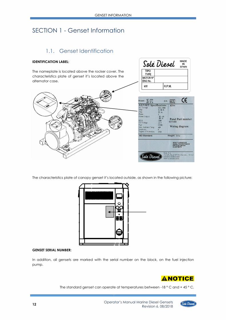
1.1. Genset Identification
IDENTIFICATION LABEL:
The nameplate is located above the rocker cover. The
characteristics plate of genset it’s located above the
alternator case.
The characteristics plate of canopy genset it’s located outside, as shown in the following picture:
GENSET SERIAL NUMBER:
In addition, all gensets are marked with the serial number on the block, on the fuel injection
pump.
The standard genset can operate at temperatures between -18 ° C and + 45 ° C.

GENSET INFORMATION
13 Operator’s Manual Marine Diesel Gensets
Revision 6. 08/2018
1.2. Genset Parts Identification
Gensets: 7GSC / 8 GSCAC / 10 GTAC / 10 GSC / 11 GTC / 12 GSAC
¹ Only for 7 GSC and 8 GSAC gensets.
PIECE ELEMENT
1 Oil filter
2 Oil level stick
3 Oil fill cap
4 Oil drain tube
5 Fuel filter
6 Drain plug
7 Fuel feed pump
8 Electric fuel feed
pump 12V
9 Nozzles
10 Air inlet elbow
11 Wet exhaust elbow
12 Relays
13 Air filter
14 Sea water pump
15 Fresh water pump
16 Heat exchanger
17 Coolant drain plug
18 Coolant fill plug
19 Starter
20 Alternator DC
21 Belt
22 CA alternator
23 Stop solenoid
24 Glow plug
25 Anti-vibration mounts
26 Regulator support box¹

TRANSPORT, HANDING AND STORAGE
14
Operator’s Manual Marine Diesel Gensets
Revision 6. 08/2018
Gensets: 14 GSC / 14 GTAC / 17 GASAC / 17 GTC / 20 GTAC
PIECE ELEMENT
1 Oil filter
2 Oil level stick
3 Oil fill cap
4 Oil drain tube
5 Fuel filter
6 Relays
7 Fuel feed pump
8 Electric fuel feed
pump 12V
9 Nozzles
10 Air inlet elbow
11 Wet exhaust elbow
12 Air filter
13 Sea water pump
14 Fresh water pump
15 Heat exchanger
16 Coolant drain plug
17 Coolant fill plug
18 Starter
19 Alternator DC
20 Belt
21 CA alternator
22 Stop solenoid
23 Glow plug
24 Anti-vibration mounts

TRANSPORT, HANDING AND STORAGE
15 Operator’s Manual Marine Diesel Gensets
Revision 6. 08/2018
SECTION 2 - Transport, Handling and Storage
2.1. Reception
When the genset is delivered make sure that the packing has not been damaged during
transport and that it has not been tampered with or that components inside the packing have
been removed (see information marked on covers, bases and cartons).
Place the packed genset as close as possible to the place of installation and remove the
packing material, checking that the goods supplied correspond to the order specifications.
If you notice damage or missing parts, inform SOLÉ DIESEL S.A. after-sales departments
and the carrier immediately and forward photographic evidence of the damage.
After inspecting the goods if you notice damage, write a reservation on the delivery
note. Have the carrier countersign the note and advise SOLÉ DIESEL S.A., preferably by mail
2.2. Transporting and Handling the Packed Genset
When lifting and transporting the genset use EXCLUSIVELY a forklift or bridge crane of
appropriate load capacity, with chains equipped with safety hooks suitable for lifting the load.
The use of any other system automatically invalidates the insurance guarantee against
possible damage to the genset.
To unpack the genset, you must follow these steps:
1. Remove the cardboard crate.
2. Lift the genset using a forklift and suitable
chains, which hook to the genset
eyebolts.
3. Transfer the genset to the intended
position of installation.
4. Remove the wooden base.
5. Begin installation operations.

TRANSPORT, HANDING AND STORAGE
16
Operator’s Manual Marine Diesel Gensets
Revision 6. 08/2018
2.3. Transporting and Handling the Unpacked Genset
When the genset is unpacked and ready for transport, use EXCLUSIVELY the appropriate
lifting eyebolts.
For gensets 8 GTC / 10 GTAC / 7
GSC / 8 GSAC
For gensets 11GTC / 14GTAC / 10
GSC / 12 GSAC / 17 GTC / 20 GTAC / 14
GSC / 17 GSAC
2.4. Storage of Packed and Unpacked Genset
If the genset is left idle for prolonged periods, the client must check the possible
conditions of conservation in relation to the place of storage.
If the genset is unused for prolonged periods and stored, observe all the relative
technical specifications.
The treatment of the genset for storage is guaranteed for 6 months after the time of delivery.
If the user decides to start the genset after a long-time period, this must be done in the
presence of an authorized technic.

INSTALLATION
17 Operator’s Manual Marine Diesel Gensets
Revision 6. 08/2018
SECTION 3 – Installation
3.1. Angle of Installation
Make sure the genset is installed on a level surface. Otherwise, the following angular
operation maximum is permitted:
Continuously Temporary
8 GTC / 10 GTAC / 7 GSC / 8 GSAC / 11 GTC / 14 GTAC /
10 GSC / 12 GSAC / 17 GTC / 20 GTAC / 14 GSC / 17 GSAC 25º 30º (Max. 30 min.)
If the genset operates in these conditions, check Section 5.4. Lubrication System.
3.2. Genset installation
Follow these steps to install the genset:
1. FIX GENSET. See 10.4 Genset Dimensions (mounting holes) and section 9 Tightening Torques.
2. CONNECT EXHAUST OUTLET. See 10.4 Genset Dimensions.
1. WET EXHAUST OUTLET
2. DRY EXHAUST OUTLET + SEAWATER OUTLET
3. CONNECT SIPHON BREAKER. (if installed) See 10.4 Genset Dimensions.
4. CONNECT SEAWATER INLET. See 10.4 Genset Dimensions.
5. CONNECT FUEL INLET. See 10.4 Genset Dimensions.
6. CONNECT LEAK COOLANT OUTLET. See 10.4 Genset Dimensions.
7. FILL WITH OIL. See 5.4 Lubrication System.
8. FILL WITH COOLANT. See 5.6 Cooling System.
9. CHECK EACH PIPE CONNECTION for oil or coolant leaks.
10. CONNECT TO EARTH. See 5.5 Fuel System.
11. PRIME THE FUEL SYSTEM. See 5.5 Fuel System.
12. CONNECT TO SCO PANEL. See Section 10.4 Genset Dimensions.
13. CONNECT TO BATTERY. Follow label battery connection into the genset.
It is necessary to install a waterlock (supplied as accessory) in the exhaust system to avoid
water ingestion (See section 6.7).

OPERATION
18
Operator’s Manual Marine Diesel Gensets
Revision 6. 08/2018
SECTION 4 - Operation
4.1. Prestart Checklist
Follow these checks and inspections to ensure the correct genset operation. In addition,
some checks require verification after unit starts.
AIR CLEANER: Check for a clean and installed air cleaner element to prevent unfiltered
air from entering the genset.
AIR INLETS: Check for clean and unobstructed air inlets.
BATTERY: Check for tight battery connections.
COOLANT LEVEL: Check the coolant level according to coolant circuit capacity.
DRIVE BELTS: Check the belt condition and tension of the coolant pump and battery
charging alternator belt.
EXHAUST SYSTEM: Check for exhaust leaks and blockages. Check the silencer and piping
condition and check for tight exhaust system connections.
Check that the exhaust outlet is unobstructed.
FUEL LEVEL: Check the fuel level and keep the tank(s) full to ensure adequate fuel supply.
OIL LEVEL: Maintain the oil level below dipstick high mark and above dipstick low mark.
OPERATING AREA: Check for obstructions that could block the flow of admission air.
SEAWATER PUMP PRIMING: Prime the seawater pump before initial startup. To prime the
pump:
- Close the seacock.
- Remove the hose from the seawater-filter outlet.
- Fill the hose and seawater pump with clean water.
- Reconnect the hose to the water filter outlet.
- Open the seacock.
Confirm seawater pump operation on startup as indicated by water discharge from the
exhaust outlet.
4.2. Genset Operation at Low Temperatures
Whenever the atmospheric temperature drops below zero, the following series of
circumstances occur:
▪ The cooling liquids may freeze.
▪ The oil becomes thicker.
▪ There is a drop in the voltage at the battery terminals.
▪ The inlet air temperature is low and the genset has difficulty in starting.
▪ The fuel loses fluidity.
To prevent the damage caused by low temperature operation, the genset should be
prepared:
1. Use special low temperature coolant or suitable anti-freezing agent concentration.
2. Close the seawater cock, when the genset is stopped. Open the seawater filter
cover and start the genset adding a mixture of freshwater and suitable anti-freezing
agent concentration (see package labels) until the seawater circuit is filled

OPERATION
19 Operator’s Manual Marine Diesel Gensets
Revision 6. 08/2018
completely. Stop the genset and replace the seawater filter cover. Before starting
the genset again, open the seawater cock.
Repeat this operation whenever the genset is used at temperatures below 0ºC.
3. Use oil with suitable quality and viscosity. SAE 15W40 is recommended. Under
extreme conditions contact with technical support.
4. Cover battery with an adequate material to protect it against the cold. Check that
the battery is fully charged.
It is also advisable to use a dielectric spray on the electrical connections.
5. When starting the genset, make sure that the glow plugs become hot enough.
6. If necessary, replace the diesel oil by a specified diesel oil type for low temperatures.
The accumulation of impurities in the fuel tank could cause faulty firing.
All gensets not in use are subject to rusting and corrosion of machined surfaces that are
not protected with a paint coating. The degree of corrosion depends on meteorological
changes and climatic conditions. The following recommendations are therefore of a general
nature but they will help prevent or reduce the risk of damage due to rusting.
4.3. Winterzation and Preservation
If the boat is not going to be used for a long period of time or during the winter, certain
tasks must be carried out to keep it in perfect operating condition. If there is no care, the inside
parts can oxidize and cause damage on the genset. When the genset is stored, steps indicated
below have to been follow:
1. Clean the outer surface of the genset.
2. Bleed the seawater circuit by filling it with fresh water. Fill the seawater circuit again
with a mixture of fresh water and anti-freezing agent.
3. Remove the impeller from the seawater pump, clean it with fresh water and store it in
place protected from moisture and sunlight.
4. Renew and refill the heat exchanger to the maximum level with a mixture of fresh
water and anti-freezing agent.
5. Renew the oil and oil filter in the genset.
6. Cover the air intake.
7. If the fuel tank is small, empty it completely and clean it; fill it up again with a mixture
of diesel and anti-corrosion additive. Solé Diesel S.A. recommends DIECYL PLUS. Add
one measure of this additive for every 25 liters of diesel. On the other hand, if the fuel
tank is large, add 1 liter of this additive for every 500 liters of diesel.
8. Clean and dry the area where the genset is installed.
9. Loosen the belts.
10. Apply dielectric spray on the electrical connection, disassemble the battery and
charge it several times during the time it is not being used.
11. Apply moisture repellent spray on the motor.

OPERATION
20
Operator’s Manual Marine Diesel Gensets
Revision 6. 08/2018
4.4. Maintenance during the storage
During the long genset storage, it has to be stored inside a ventilated area and free of
humidity.
When the genset stay stopped for 3 months or more, inside parts can be oxidize and lost
the oil film. As a result, the genset could to size up after the storage. To avoid this, the genset must
work periodically during the storage.
Realize the following steps at least once per month:
1. In case that has a battery next to the genset, check the electrolyte level and fill it.
2. Start the genset during approximately 10 seconds.
3. Stop the genset during 1 minute. Repeat this action two or three times.
4. Be sure that oil pressure of the genset increase.
5. Get the genset work during 5 or 10 minutes without load, as maintenance operation.
4.5. Restoration of Operational Conditions
When starting up the genset again after winter lay-up, certain operations must be
performed. Follow these steps:
1. Fill the fuel tank with clean diesel. The mixture of diesel oil and anti-corrosion additive
in tank for winter lay-up can be used to operate the genset.
2. Get the genset work during 5 or 10 minutes without load, as maintenance operation.
3. Check the fuel filter. If the filter is clogged, replace the filter.
4. Renew the oil in the genset.
5. Check the condition of coolant circuit’s rubber hoses.
6. Reconnect the battery and apply a layer of neutral Vaseline to the battery terminals.
7. Remove the nozzle supports and clean them. If possible, verify the setting of the
nozzles at a workshop. Then install the clean nozzles.
8. Connect the cooling and exhaust system. Open the seawater cock.
9. Verify whether there are any leaks in the fuel, coolant and oil systems.

SYSTEMS AND SCHEDULED MAINTENANCE
21 Operator’s Manual Marine Diesel Gensets
Revision 6. 08/2018
SECTION 5 - Systems and Scheduled Maintenance
5.1. Operating Description
Information of special tools required and basic safety precautions.
Disassembly:
✓ Use the correct tools and instruments. Serious injury or damage to the genset can
result from using the wrong tools and instruments.
✓ Use an overhaul stand or work bench if necessary. Also, use assembly bins to keep
the genset parts in order of removal.
✓ Lay down disassembled or cleaned parts in the order in which they were removed.
This will save you time at reassembly.
✓ Pay attention to the marks on assemblies, components and parts for positions or
directions. Put on your own marks, if necessary, to aid reassembly.
✓ Carefully check each part for faults during removal or cleaning. Signs of abnormal
wear will tell if parts or assemblies are functioning improperly.
✓ When lifting or carrying heavy parts, get someone to help you if the part is too
awkward for one person to handle. Use jacks and chain blocks when necessary.
Reassembly:
✓ Wash all genset parts, except oil seals, O-rings, rubber seals, etc. in cleaning solvent
and dry them.
✓ Use only the correct tools and instruments.
✓ Use only good quality lubricating oils and greases. Be sure to apply a coat of oil,
grease, or sealant to parts as specified.
✓ Use a torque wrench to tighten parts when specified tightening torques is required.
✓ Replace all gaskets and packing. Apply appropriate amount of adhesive or liquid
gasket when required.
✓ Increase the frequency of maintenance in harsh duty conditions (frequent stops and
starts, dusty surrounding, prolonged winter season, no-load running).
✓ Risk of burns during maintenance operations carried out when the genset is hot.
Wear suitable safety clothing.
✓ It is strictly forbidden to clean the genset with compressed air.
✓ It is strictly forbidden to perform maintenance/cleaning operations in the presence of
moving parts.
✓ Use gloves, overalls, etc. to protect the body from burns.
5.2. Periodic Maintenance Schedule
The maintenance and fault diagnostic procedures involve risks that may cause severe
injury or even death. These procedures should therefore be carried out solely by qualified
electrical and mechanical specialists. Before any maintenance and cleaning work, make sure
that there are no moving parts, that the generator housing has cooled to ambient temperature,
that the electricity generating set cannot be accidentally started up and that all procedures are
strictly observed.

SYSTEMS AND SCHEDULED MAINTENANCE
22 Operator’s Manual Marine Diesel Gensets
Revision 6. 08/2018
Intervals
Inspection Item Daily
1st 20h-
50h
Every
200h
Every
400h
Every
800h
Every
year
Every 2
years
Winter storage and
Preservation
General
Screw tightening, fastening.
I
I
Genset block.
CL
Valve clearance.
I
Exhaust gas, noise and vibrations. I
Compression pressure.
I
Lubrication system* Genset oil. I C C
C
C
Oil filter.
C C
Fuel system
Fuel level. I
Fuel tank.
CL
E/CL/I
Fuel filter.
C
Water separator filter (if
applicable). E
C
Injection pump.
I
Injector.
I
Intake system Air filter.
I
C
C
I
Cooling system Coolant. I
C
C
Salt water circuit.
I/CL
Anode I/C
Water filter. I CL CL
Sea water cock. I
Salt water pump impeller.
I/C I
I/CL
Electrical system
Incandescent glow plug.
I
Starter motor and alternator 12/24V.
I
Alternator 12/24V belt and tension.
I
I C
I
Battery level.
I I
C
* Use oil with 15W40 viscosity and no less than ACEA E5 or API CH-4/SJ quality.
.
I: Inspect, adjust or fill. E: Empty. C: Change. CL: Clean.
.

SYSTEMS AND SCHEDULED MAINTENANCE
23 Operator’s Manual Marine Diesel Gensets
Revision 6. 08/2018
5.3. General
Solé Diesel offers, for these genset models, a maintenance kit:
Maintenance task. Screw tightening, fasteningt
For details of tightening torques see Section 9 Torques.
Maintenance task. Valve clearance inspection
The rocker cover must be dismounted to check the valve clearance. This operation must
be carried out when the genset is cold.
Item Assembly standard
Valve clearance (cold setting) Inlet
0,25 mm Exhaust
Inspection
1. Insert the appropriate thickness gauge between the
rocker arm and valve cap to check the clearance.
2. Loosen the rocker nut (1).
3. Tighten or loosen adjusting screw (2) to adjust valve
clearance by checking thickness with thickness gauge
(3).
4. When you have adjusted the thickness, tighten the rocker
nut and recheck the thickness.
With piston nº 1 in the top dead centre of the compression cycle, adjust the play of the
intake and exhaust valves of cylinder nº 1. Proceed similarly as with the other cylinders. The
position of the BTDC can be confirmed with thea lining signs of the ditribution or timming cover
and the crakshaft pulley.
The adjustment of the valve play must be made after the cylinder head screws are again
tightened.(Strictly comply with the operation sequence indicated in the heading 4.1)
On board spare parts
Reference
8 GTC / 10 GTAC / 7 GSC / 8
GSAC / 11 GTC / 14 GTAC /
10 GSC / 12 GSAC / 17 GTC /
20 GTAC / 14 GSC / 17 GSAC
13840110

SYSTEMS AND SCHEDULED MAINTENANCE
24
Operator’s Manual Marine Diesel Gensets
Revision 6. 08/2018
Maintenance task. Compression pressure inspection
Start by:
1. Make sure the genset oil level, air cleaner, starting
motor and battery are well-conditioned.
2. Start the genset and allow it to warm up
thoroughly, until 50ºC or more coolant
temperature.
Measure the compression pressure on all cylinders:
1. Remove the injection nozzle from the cylinder head where the compression pressure is to
be measured.
2. Attach the compression pressure gauge.
3. Disconnect the stop solenoid connector (the fuel supply shut off) and crank the genset
by means of the starter, and read the compression pressure gauge indication when the
genset is running at specified speed.
4. If the compression pressure is lower than repair limit, check the genset parts affected.
- It is not a good practice to measure the compression pressure on only few cylinders,
and presume the compression on the remaining cylinders.
- Compression pressure varies with genset speed. Check genset speed when
measuring the compression pressure.
- The compression pressure will be slightly higher in a new or overhauled genset due to
new piston rings, valve seats, etc.
Model Genset speed Compression pressure Repair limit
8 GTC / 10 GTAC /
7GSC / 8 GSAC 250 a 280 rpm
2,84 a 3,14 MPa
(29 a 32 kgf/cm2)
2,45 MPa
25 kgf/cm2
11 GTC / 14 GTAC /
10 GSC /12 GSAC /
17 GTC / 20 GTAC /
14 GSC /17 GSAC /
290 rpm 3,14 MPa
(32 Kgf/cm2)
2,45 MPa
(25 kgf/cm2)

SYSTEMS AND SCHEDULED MAINTENANCE
25 Operator’s Manual Marine Diesel Gensets
Revision 6. 08/2018
5.4. Lubrication System
Circuit description
The lubrication circuit is forced by the trochoid gear pump, and it is composed of the following
elements.
*Including filter change (0,5l)
Oil specifications
Use oil with 15W40 viscosity (this is an all-season oil for temperatures
ranging between -15ºC and +40ºC) or select the most suitable oil viscosity for
the atmospheric temperatures on which the genset is going to be operated.
On the other hand, use oil quality no less than ACEA E5/E3 or API CH-4/SJ. Other
genset oils may affect warranty coverage, cause internal genset components
to seize and/or shorten genset life.
Never mix different types of genset oil. This may adversely affect the lubricating
properties of the genset oil.
Maintenance task. Oil filter change
The oil filter is located under inlet manifold of the engine.
Remove oil filter with a belt wrench. When fitting a fresh oil filter,
smear a small quantity of oil into the annular seal and firmly genset
and check oil is not leaking.
PIECE ELEMENT
1 Main gallery
2 Oil pump
3 Oil strainer
4 Oil pan
5 Oil filter
6 Pressure relief valve
* Oil circuit capacity (L)
8 GTC / 10 GTAC /
7 GSC / 8 GSAC 4,1
11 GTC / 14 GTAC /
10 GSC / 12 GSAC 4,2
17 GTC / 20 GTAC /
14 GSC / 17 GSAC 6,0
SYSTEMS AND SCHEDULED MAINTENANCE
26
Operator’s Manual Marine Diesel Gensets
Revision 6. 08/2018
Maintenance task. Oil level check
Check the oil level in the crankcase daily or before each start-up to ensure that
the level is between the upper (Max mark) and lower (Min mark) lines on the dipstick. To check
the oil level:
1. Remove the dipstick
2. Wipe the dipstick end
3. Reinsert inside the guide
4. Remove it again to see the oil level
If the genset is fitted inclined, the oil dipstick must be modified to avoid problems of
aspiration by the oil pump. Follow next steps to perform the modification:
1. With the engine in horizontal position, fill the oil circuit until the dipstick minimum mark
and take note of the quantity of oil used.
2. With the engine in horizontal position, fill the oil circuit until the dipstick mark
maximum and take note of the quantity of oil used.
3. With the engine inclined, fill the oil circuit with the maximum oil quantity, according
to the previous amount
Then, extract the difference between the maximum and minimum quantity, and mark the new
minimum.
Do not operate the genset if the oil level is below the Min mark or above the Max mark.
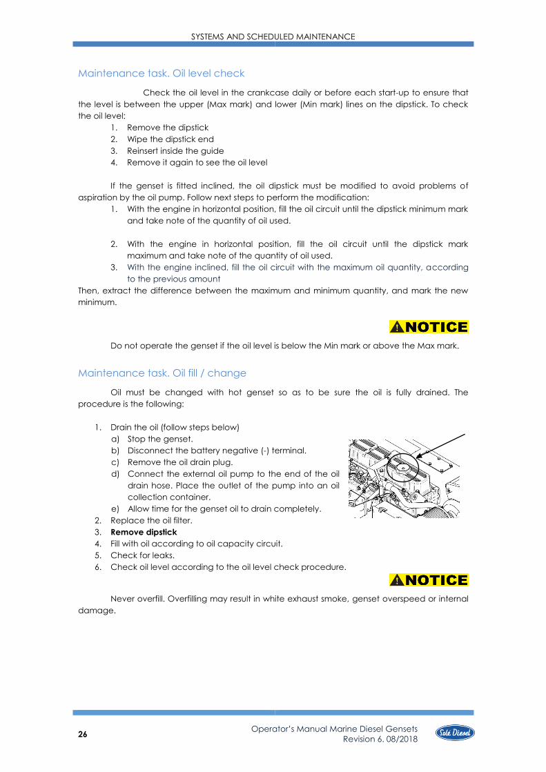
Maintenance task. Oil fill / change
Oil must be changed with hot genset so as to be sure the oil is fully drained. The
procedure is the following:
1. Drain the oil (follow steps below)
a) Stop the genset.
b) Disconnect the battery negative (-) terminal.
c) Remove the oil drain plug.
d) Connect the external oil pump to the end of the oil
drain hose. Place the outlet of the pump into an oil
collection container.
e) Allow time for the genset oil to drain completely.
2. Replace the oil filter.
3. Remove dipstick
4. Fill with oil according to oil capacity circuit.
5. Check for leaks.
6. Check oil level according to the oil level check procedure.
Never overfill. Overfilling may result in white exhaust smoke, genset overspeed or internal
damage.

SYSTEMS AND SCHEDULED MAINTENANCE
27 Operator’s Manual Marine Diesel Gensets
Revision 6. 08/2018
5.5. Fuel System
Circuit description
The fuel system is based on a fuel feed pump and an in-line mechanical injection pump.
Fuel specifications
Use ASTM diesel fuel No.2-D for the best genset performance, to prevent genset
damage. Never use kerosene, heavy diesel fuel or biodiesel. It is essential to use clean and
filtered diesel oil.
The use of diesel oil that not complies with the technical specifications may affect
warranty coverage and cause serious damage in the injection system and internal genset
components.
Maintenance task. Fuel Level Inspection
Periodically, it is necessary to check the fuel level to assure the operation of the genset.
On top of that, if fuel pump sucks air when the fuel level is lower than pump suction, it could
break.
Whenever possible, keep the fuel tank full. The temperature changes may cause
condensation of the damp air present in the tank and this water accumulates at the bottom. It
can cause an increase of corrosion or an impossibility of starting the genset if this water is aspired
by the fuel pump.
Maintenance task. Fuel tank clean
The fuel impurities could obstruct the suction pump. For this reason, drain out the content
of the fuel tank to remove condensate and any foreign material. Then, wash the tank with fuel
and refill it.
Maintenance task. Water separator filter purge
The fuel system has to have a water separator filter (supplied as accessory)
to avoid the inlet of water in the fuel circuit. According to the maintenance plan it is
necessary to purge the filter to eliminate water periodically. This is the procedure:
1. Loosen the bottom nut to eliminate water.
2. Shut it off again.
3. Check for any leakage.
PIECE ELEMENT
1 Fuel injection nozzle
2 Fuel injection pipe
3 Fuel leak-ok pipe
4 Injection pump
5 Feed pumps
6 Fuel filtre
7 Tank (supplied as accessory)
8 Fuel decanting filter (supplied as
accessory)
9 Fuel intake pipe (supplied as
accessory)

SYSTEMS AND SCHEDULED MAINTENANCE
28
Operator’s Manual Marine Diesel Gensets
Revision 6. 08/2018
Maintenance task. Fuel filter change
Procedure to change the fuel filter:
1. Close the fuel supply valve.
2. Disconnect fuel pipes from the fuel filter.
3. Remove fuel filter with a bell key.
4. Place a new fuel filter.
5. Reconnect fuel pipes from the fuel filter.
6. Open the fuel supply valve.
7. Once finished with this operation, start the genset and check for oil leaks.
Wash hands after any contact with diesel fuel.
Maintenance task. Injection pump inspection
The injection pump is adjusted at factory and should never be adjusted carelessly. Such
adjustment, whenever is required, shall be made by a SOLÉ DIESEL licensed service shop, since a
precision pump monitor and skill knowledge are required.
You must check:
- The presence of exhaust smoke color.
Procedure: quickly accelerate genset.
Criteria: no remarkably black smoke exhaust, and correct function of fuel cut-off
solenoid
- Any leaks at the body injection pump or fuel lines
Maintenance task. Injector inspection
To check the injection pressure of injectors (opening pressure)
you have to follow these steps:
1. Remove nozzle and washer.
2. Install the injection nozzle on the tester. Slowly operate the tester
handle full strokes to bleed (remove) air from the pipe and nozzle.
3. Make a slow increase in pressure by operating the tester handle
at a speed of more than one stroke per second while observing
the pressure gauge.
4. The pressure gauge reading will slowly increase and, when the
nozzle starts discharging fuel, it will go down fast. Take the gauge
reading right then as the injection pressure.
5. to adjust the injection pressure, increase or decrease
the amount of shims fitted to the nozzle holder.
6. Look at the orifice discharge pattern (shape of discharge) when
fluid begins to flow through the injection nozzle. The discharge must
be finely and uniformly atomized. Any change is an indication of a bad nozzle.
7. If the nozzle is bad, remove the tip from the nozzle and wash
needle valve and body in clean washing solution.
And if the nozzle is still bad after the tip has been washed,
replace the tip.
Injection pressure 13 MPa (140 kgf/cm2)
Washer

SYSTEMS AND SCHEDULED MAINTENANCE
29 Operator’s Manual Marine Diesel Gensets
Revision 6. 08/2018
When installing the new tip, remove synthetic resin film from the tip and slide the needle
valve in the body in clean diesel fuel to wash off inhibitor completely
8. The washer shown on figure must be replaced.
When testing the injection nozzle, keep its tip pointed away from the operator. Fuel from
the orifices in the tip of the nozzle is under high pressure and can cause injury to the operator.
Maintenance task. Bleeding air from the fuel system
On the first start-up of the engine, and if this has operated with the fuel tank empty, air
may enter the feed system, and it is necessary to purge this. To carry out the priming/purge of the
fuel system, proceed as follows:
1. Check fuel cock located at the tank delivery is open.
2. For engines equiped with Ronim-V and SMI gearboxes, then operate repeatedly (for
6 or 7 times) the lever ofthe fuel pump). If the manual pump valve is clogged,
difficult bleddingcan result. In such a case, remove the air vent bolt and inlet-side
hose from the filter and clean the valve with presssure air.
3. For engines equiped with electrical priming puma, operate the key to “ON” position.
Do not run the starter motor for more than 20 seconds at a time.
The air bledding from the injection pump and from the injectors is automatic.
Once this operations have been terminated proceed to start the engine.
When fuel overflows from the injection pipes, wipe thoroughly with a cloth. Spilled fuel is a
fire hazard.
5.6. Cooling System
The genset cooling system is based on coolant circulation controlled by centrifugal pump
with thermostatic control and heat exchanger, where the coolant is refrigerated by sea water.
Moreover, the exhaust manifold is cooled also by sea water.
Coolant circuit description
PIECE ELEMENT
1 Coolant pump
2 Heat exchanger
3 Thermostat
Seawater circuit description
PIECE ELEMENT
0 Bottom cock
1 Intake connection with water
filter
2 Water pump
3 Water / W
4 Turbocharger
5 Gear box cooler (only SMI-R”
Gearbox)
Model Coolant circuit capacity (L)
8 GTC / 10 GTAC /
7 GSC / 8 GSAC 3,5
11 GTC / 14 GTAC /
10 GSC / 12 GSAC 6,25
17 GTC / 20 GTAC /
14 GSC / 17 GSAC 8,0

SYSTEMS AND SCHEDULED MAINTENANCE
30 Operator’s Manual Marine Diesel Gensets
Revision 6. 08/2018
Coolant specifications
It is recommended use SOLÉ DIESEL 50% coolant or another coolant with similar
specifications. On the other hand, distilled water with an anti-freezing agent is also suitable. The
anti-freezing agent concentration according to operating conditions is specified in anti-freezing
agent package labels. It is advisable select the anti-freezing agent concentration based on a
temperature approx. 5ºC under the actual atmospheric temperature.
Other genset coolants may affect warranty coverage, cause an internal build-up of rust
and scale and/or shorten genset life.
Never mix different types of coolants. This may adversely affect the properties of the
genset coolant.
Maintenance task. Coolant check
Allow the genset to cool. Release pressure from the cooling system before removing the
pressure cap. To release pressure, cover the pressure cap with a thick cloth and then slowly turn
the cap counterclockwise. Remove the cap after pressure has been completely released and
the genset has cooled. Check the coolant level at the tank, the level must be approximately 3/4
full. v
Maintenance task. Coolant fill / change
1. Drain off all the coolant by opening
the two drain plugs, one in the heat
exchanger and the other in the
cylinder block.
2. Close the drain plugs.
3. Remove bleeding bolt of thermostat
holder
4. Refill to the hole in the tank cap with
coolan
Maintenance task. Seawater filter inspection
It is important to install a seawater filter (supplied as accessory) between seawater cock
and the seawater pump to avoid that any impurity might clog the seawater circuit or seawater
pump.
To clean this filter:
1. Loose the cover top, turning it.
2. Remove the filtering component and clean it.
3. Fit it again taking care that the cover is well
seated on the o-ring.
4. Start the genset to check seawater leakages.

SYSTEMS AND SCHEDULED MAINTENANCE
31 Operator’s Manual Marine Diesel Gensets
Revision 6. 08/2018
Maintenance task. Seawater pump impeller inspection
Seawater pump impeller is neoprene and cannot rotate dried. If operated without water,
the impeller can be broken. It is important therefore that a spare impeller is always available.
Impeller inspection and replacement procedure:
1. Close the seawater cock.
2. Remove the seawater pump cover plate.
3. Remove the impeller from the shaft.
4. Clean the housing.
5. Inspect the impeller for damaged, cranked, broken, missing
or flattened vanes. The impeller vanes should be straight and
flexible. If it is damaged replace with a new one.
6. Lubricate the impeller with soapy water before installation.
7. Install the impeller. During installation push and rotate the impeller in the same
direction as the genset rotation until it is thoroughly seated in the impeller housing.
8. Inspect the cover plate and gasket for corrosion and/or damage. Replace
components as necessary.
9. Lubricate the gasket with silicon grease and attach the gasket and cover plate to
the seawater pump housing.
10. Open the seacock.
11. Start the genset and check for leaks.
5.7. Inlet and Exhaust System
Exhaust circuit description
There are two possible installations of the exhaust system. You need to check the
distance between water injection point and waterline to decide which type of installation you
need. This information is specified in the following drawings.
The elements included in the drawing are essential for the correct genset operation:
- Waterlock (supplied as accessory) to prevent seawater from entering inside the
engine when it stops.
To calculate the required collector capacity, we must follow the following formula:
𝐶 = 𝜋4𝐷2 ∗ 𝐿
1000000∗ 0.5
C = collector capacity (L)
D = Inside diameter of the tube (mm)
L = Tube length (mm)
- Goose neck (supplied as accessory)
- Siphon breaker (supplied as accessory) – needed in case there is less than 150 mm
between the water injection point of wet exhaust and the waterline, or if the point of
injection is below waterline.

SYSTEMS AND SCHEDULED MAINTENANCE
32
Operator’s Manual Marine Diesel Gensets
Revision 6. 08/2018
Type 1 installation. When between water injection point of wet exhaust and waterline is
minimum 150 mm.
MA
X.
1500
mm
MIN
. 450 m
m
MIN
. 50
mm
MIN
. 150
mm
W.L.
L =
MIN
. 300
mm
L = MAX. 3000 mm
Type 2 installation. When between water injection point of wet exhaust and waterline
there is less than 150 mm or the point of injection is below waterline.
W.L.
MIN
. 4
00
mm
L = M
IN. 3
00 m
m
L = MAX. 3000 mm
MIN
. 5
0 m
m
MA
X.
15
00 m
m
MIN
. 4
50 m
m
The wet exhaust is the genset’s standard equipment. If you want dry exhaust, which is an
optional equipment, contact with our dealers
Maintenance task. Air filter inspection
Genset is provided with an intake air filter. Examine the
element and housing for damage. Replace the complete air filter if
necessary.
It is important to ensure that the combustion air is freely
supplied and freely expelled from the area.
SYSTEMS AND SCHEDULED MAINTENANCE
33 Operator’s Manual Marine Diesel Gensets
Revision 6. 08/2018
Maintenance task. Exhaust gas, noise and vibrations inspection
Inspect the exhaust system components for cranks, leaks and corrosion.
Exhaust system inspection points
1. Check the hoses for softness, cranks or dents. Replace the hoses as needed.
2. Check for corroded or broken metal parts and replace them as needed.
3. Check for loose, corroded or missing clamps. Tighten or replace the hose clamps
and/or hangers as needed.
4. Check that the exhaust outlet is unobstructed.
5. Visually inspect the exhaust system for exhaust leaks. Check for carbon or soot
residue on exhaust components. Carbon and soot residue indicates an exhaust leak.
Seal leaks as needed.
5.8. Electrical System
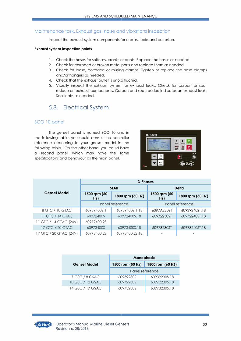
SCO 10 panel
The genset panel is named SCO 10 and in
the following table, you could consult the controller
reference according to your genset model in the
following table. On the other hand, you could have
a second panel, which may have the same
specifications and behaviour as the main panel.
Genset Model
Monophasic
1500 rpm (50 Hz) 1800 rpm (60 HZ)
Panel reference
7 GSC / 8 GSAC 60939230S 60939230S.18
10 GSC / 12 GSAC 60972230S 60972230S.18
14 GSC / 17 GSAC 60973230S 60973230S.18
Genset Model
3-Phases
STAR Delta
1500 rpm (50
Hz) 1800 rpm (60 HZ)
1500 rpm (50
Hz) 1800 rpm (60 HZ)
Panel reference Panel reference
8 GTC / 10 GTAC 60939400S.1 60939400S.1.18 6097A230ST 60939240ST.18
11 GTC / 14 GTAC 60972400S 60972400S.18 60972230ST 60972240ST.18
11 GTC / 14 GTAC (24V) 60972400.2S - - -
17 GTC / 20 GTAC 60973400S 60973400S.18 60973230ST 60973240ST.18
17 GTC / 20 GTAC (24V) 60973400.2S 60973400.2S.18 - -
SYSTEMS AND SCHEDULED MAINTENANCE
34
Operator’s Manual Marine Diesel Gensets
Revision 6. 08/2018
Battery
The minimum recommended capacity is from 60 - 80 Ah. However, this value serves as a
general reference since it relates to the maximum intensity it can offer for starting the generator
set.
The connection of the battery for a standard engine:
• Positive battery is connected to the starter.
• Negative battery is connected to the relay support.
The connection of the battery for an earth isolated engine.
• Positive battery is connected to the starter.
• Negative battery is connected to the bipolar relay.
Circuit protection
AC Breaker interrupts the genset output in the event of an overload or short
circuit. It is located in front panel as is showed in the section 10.
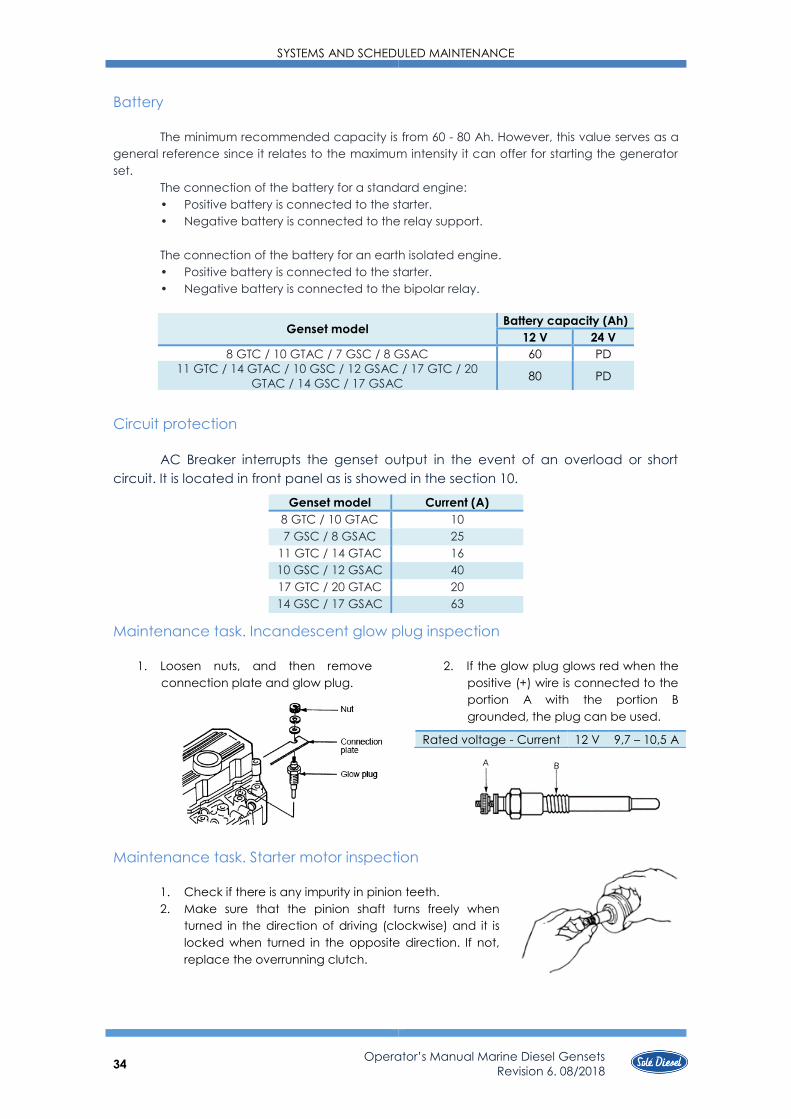
Maintenance task. Incandescent glow plug inspection
1. Loosen nuts, and then remove
connection plate and glow plug.
2. If the glow plug glows red when the
positive (+) wire is connected to the
portion A with the portion B
grounded, the plug can be used.
Maintenance task. Starter motor inspection
1. Check if there is any impurity in pinion teeth.
2. Make sure that the pinion shaft turns freely when
turned in the direction of driving (clockwise) and it is
locked when turned in the opposite direction. If not,
replace the overrunning clutch.
Genset model Battery capacity (Ah)
12 V 24 V
8 GTC / 10 GTAC / 7 GSC / 8 GSAC 60 PD
11 GTC / 14 GTAC / 10 GSC / 12 GSAC / 17 GTC / 20
GTAC / 14 GSC / 17 GSAC 80 PD
Genset model Current (A)
8 GTC / 10 GTAC 10
7 GSC / 8 GSAC 25
11 GTC / 14 GTAC 16
10 GSC / 12 GSAC 40
17 GTC / 20 GTAC 20
14 GSC / 17 GSAC 63
Rated voltage - Current 12 V 9,7 – 10,5 A
SYSTEMS AND SCHEDULED MAINTENANCE
35 Operator’s Manual Marine Diesel Gensets
Revision 6. 08/2018
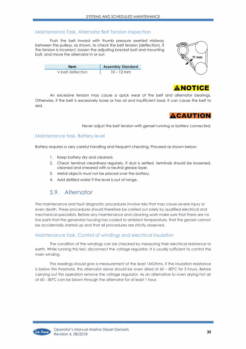
Maintenance Task. Alternator Belt Tension Inspection
Push the belt inward with thumb pressure exerted midway
between the pulleys, as shown, to check the belt tension (deflection). If
the tension is incorrect, loosen the adjusting bracket bolt and mounting
bolt, and move the alternator in or out.
An excessive tension may cause a quick wear of the belt and alternator bearings.
Otherwise, if the belt is excessively loose or has oil and insufficient load, it can cause the belt to
skid.
Never adjust the belt tension with genset running or battery connected.
Maintenance task. Battery level
Battery requires a very careful handling and frequent checking. Proceed as shown below:
1. Keep battery dry and cleaned.
2. Check terminal cleanliness regularly. If dust is settled, terminals should be loosened,
cleaned and smeared with a neutral grease layer.
3. Metal objects must not be placed over the battery.
4. Add distilled water if the level is out of range.
5.9. Alternator
The maintenance and fault diagnostic procedures involve risks that may cause severe injury or
even death. These procedures should therefore be carried out solely by qualified electrical and
mechanical specialists. Before any maintenance and cleaning work make sure that there are no
live parts that the generator housing has cooled to ambient temperature, that the genset cannot
be accidentally started up and that all procedures are strictly observed.
Maintenance task. Control of windings and electrical insulation
The condition of the windings can be checked by measuring their electrical resistance to
earth. While running this test, disconnect the voltage regulator. It is usually sufficient to control the
main winding.
The readings should give a measurement of the least 1MOhms. If the insulation resistance
is below this threshold, the alternator alone should be oven dried at 60 – 80ºC for 3 hours. Before
carrying out this operation remove the voltage regulator. As an alternative to oven drying hot air
at 60 – 80ºC can be blown through the alternator for at least 1 hour.
Item Assembly Standard
V-belt deflection 10 – 12 mm
SYSTEMS AND SCHEDULED MAINTENANCE
36
Operator’s Manual Marine Diesel Gensets
Revision 6. 08/2018
Maintenance task. Control of bearings
During maintenance control the condition of the bearing and check that no grease has
leaked: the lifespan of the bearings depends on the vibrations and axial strains they undergo
(vibrations can increase considerably with a bad alignment) and on the working conditions. So
check for any unusual signs: vibrations, unusual noises.
If undue vibrations or noises appear after long-term usage, these could be due to a worn
bearing that, if damaged, has to be replaced. No maintenance is required for the total
operating time:
A bearing lifespan is closely linked to the working conditions and environment.
Long periods of sustained vibrations can damage the bearing balls and their seat. Too
high humidity can emulsify the grease and encourage corrosion.
Intense vibrations caused by the motor or bad alignment of the components in the
genset put the bearing under stresses that will reduce its lifespan.
Maintenance task. Cleaning and lubrication
Any kind of cleaning work must be carried out with the genset shutdown and the mains
power shut off for the risk of severe hazard for persons and objects. Moreover, prior to
approaching or touching the alternator, ensure that it is at room temperature.
Make sure that the genset is shutdown and the mains power is shut off before cleaning
the outside of the genset with compressed air.
Never and for no reason whatsoever use fluids or water. Do not use compressed air to
clean internal electrical parts since this could cause short circuits or related problems.
Operating time
20.000 horas

SCO 10 PANEL
37 Operator’s Manual Marine Diesel Gensets
Revision 6. 08/2018
SECTION 6 – SCO 10 PANEL
6.1. Installation
The controller is to be mounted onto the switchboard door. Requested cutout size is
175x115mm. Use the screw holders delivered with the controller to fix the controller into the door
as described on the pictures below.
Then, it is necessary to connect male connector (engine installation wire) to female connector
(SCO 10).
Kit second panel SCO 10 (ref. 60974600S)
The first step to install the remote SCO 10 is to Connect the communication wire from
main SCO 10 to REMOTE SCO 10 as is specified in wiring diagrams. The black wire in REMOTE SCO
10 communication wire end must be connected to earth.
Finally, it is necessary to connect to battery (red wire to positive and black wire to negative).
According to the distance required between the main and remote SCO10, the following cable
lengths:
Length 12 meters 24 meters 36 meters 60 meters
Reference 60972104 60972105 60972110 60972113
REMOTE SCO 10 communication wire
end
MAIN SCO 10 communication wire
end
Connect to battery
12/24 V
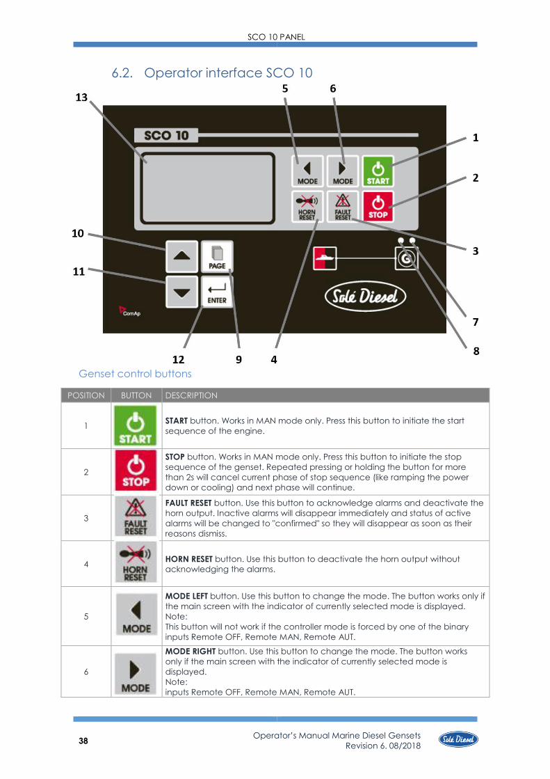
SCO 10 PANEL
38
Operator’s Manual Marine Diesel Gensets
Revision 6. 08/2018
6.2. Operator interface SCO 10
Genset control buttons
POSITION BUTTON DESCRIPTION
1
START button. Works in MAN mode only. Press this button to initiate the start
sequence of the engine.
2
STOP button. Works in MAN mode only. Press this button to initiate the stop
sequence of the genset. Repeated pressing or holding the button for more
than 2s will cancel current phase of stop sequence (like ramping the power
down or cooling) and next phase will continue.
3
FAULT RESET button. Use this button to acknowledge alarms and deactivate the
horn output. Inactive alarms will disappear immediately and status of active
alarms will be changed to "confirmed" so they will disappear as soon as their
reasons dismiss.
4
HORN RESET button. Use this button to deactivate the horn output without
acknowledging the alarms.
5
MODE LEFT button. Use this button to change the mode. The button works only if
the main screen with the indicator of currently selected mode is displayed.
Note:
This button will not work if the controller mode is forced by one of the binary
inputs Remote OFF, Remote MAN, Remote AUT.
6
MODE RIGHT button. Use this button to change the mode. The button works
only if the main screen with the indicator of currently selected mode is
displayed.
Note:
inputs Remote OFF, Remote MAN, Remote AUT.

SCO 10 PANEL
39 Operator’s Manual Marine Diesel Gensets
Revision 6. 08/2018
Genset operator indicators
POSITION DESCRIPTION
7 Genset failure. Red LED starts flashing when genset failure occurs. After FAULT RESET button is
pressed, the light steadies (if an alarm is still active) or turns off (if no alarm is active).
8
Genset voltage OK. Green LED is on if the generator voltage is present and within limits.
Note:
The limits for the generator voltage and frequency are given by setpoints in the Gener
Protect group.
Display and control buttons
POSITION BUTTON DESCRIPTION
9
PAGE button. Use this button to switch over display pages. See Display Screens
and Pages Structure section below this table for more details.
10
UP button. Use this button to move up or increase a value.
11
DOWN button. Use this button to move down or decrease a value.
12
ENTER button. Use this button to finish editing a setpoint or moving right in the
history page.
13
Graphic B/W display, 128x64 pixels
6.3. Display Screens and Pages Structure
The displayed information is structured into "pages" and "screens". Use PAGE button to switch
over the pages.
1. The Measurement page consists of screens which display measured values like voltages,
current, oil pressure etc., computed values like genset power, statistic data and the
alarm list on the last screen.
2. The Setpoints page contains all setpoints organized in groups and also a special group
for entering password.
3. The History log page shows the history log in reverse order, so the last record is displayed
first.

SCO 10 PANEL
40
Operator’s Manual Marine Diesel Gensets
Revision 6. 08/2018
• Voltage between phases and neutral.
• Voltage between different phases.
• Genset frequency.
• Electric current/phase current (if the
amperometric kit is installed).
• OIL pressure.
• Engine temperature (cooling).
• Fuel level.
• Battery voltage.
• BI1: Remote control – Start or Stop.
• BI2: Alarm / Temperature switch (shutdown).
• BI3: Emergency STOP.
• BI4: Alarm / Pressure switch.
• BI5: Sd Override.
• BI6: Exhaust gas temperature (optional kit).
Measurement
Binary Inputs –Binary signals form the genset to the control panel.
• Ready genset / No ready
• Power factor (if the amperometric
kit is installed).
• RPM
• Timer seconds of each genes
phase.
• Active power pointer (if the
amperometric kit is installed).

SCO 10 PANEL
41 Operator’s Manual Marine Diesel Gensets
Revision 6. 08/2018
• BO1: Crancking signal (start)
• BO2: Stop solenoid, f current comes or not. Fuel
Solenoid corresponds to STOP ETR
• BO3: Air Valves: corresponds to a feed pump
• BO4: Pre-heating glow plugs
• BO5: Horn (free, is not wired)
• BO6: Alarm. If the system detects an alarm
(free, is not wired)
• The left column shows the active power of
each phase and total current (if the
amperometric kit is installed).
• The middle column shows the power
factor of each phase and total current (if
the amperometric kit is installed).
• The right column shows the apparent
power of each phase and total.
Binary Outputs – Control panel orders to the genset.
If you do not understand the
description of the alarm it is
recommended to change the
language to English, the original
language. If still in doubt, contact to
factory.

SCO 10 PANEL
42
Operator’s Manual Marine Diesel Gensets
Revision 6. 08/2018
+
Setpoint. Controller information screen
If the panel is more than 5
seconds in a screen, it returns
to initial screen automatically.
In this case, you must begin all
the procedure again.
Enter
Page
Page
Page
Hold the ENTER and
PAGE button at the
same time
mismo tiempo.
Page
+ Enter

SCO 10 PANEL
43 Operator’s Manual Marine Diesel Gensets
Revision 6. 08/2018
Set point. Maintenance hours change
When the following warning appears in the Alarm list screen of SCO 10: First of all you
must carry out the maintenance tasks according to the Maintenance task table, attached in the
end. You also can consult this information in the Warranty manual. Then, you must accept the
alarm (press FAULT RESET button) and put the 200 hours to the next maintenance period, in
accordance with these instructions:
Page
Enter
+
+ Page
Page
r
+
Enter
Enter
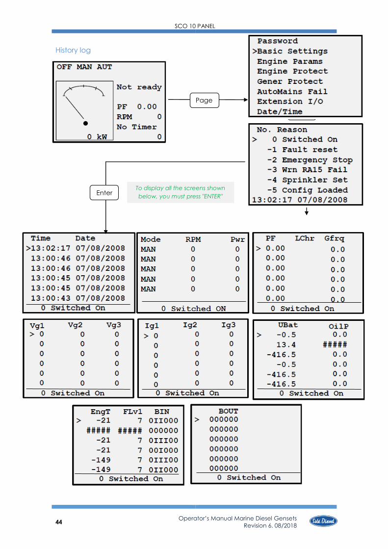
SCO 10 PANEL
44
Operator’s Manual Marine Diesel Gensets
Revision 6. 08/2018
History log
Page
Page
To display all the screens shown
below, you must press "ENTER" Enter
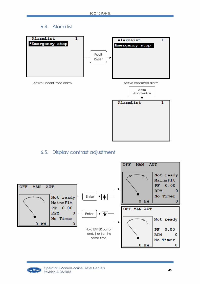
SCO 10 PANEL
45 Operator’s Manual Marine Diesel Gensets
Revision 6. 08/2018
+
+
6.4. Alarm list
6.5. Display contrast adjustment
Alarm
desactivation
Active unconfirmed alarm Active confirmed alarm
Enter
Enter
Hold ENTER button
and, ↑ or ↓at the
same time.
Fault
Reset

SCO 10 PANEL
46
Operator’s Manual Marine Diesel Gensets
Revision 6. 08/2018
6.6. Change language
You must follow these steps to change the panel language.
Hold ENTER button
and, at the same
time, press PAGE
button.
Select with ↑ o ↓
button, then press
ENTER button.
✓ The lenguage is changed correctly.
If the panel is more than 5
seconds in a screen, it returns
to initial screen automatically.
In this case, you must begin all
the procedure again.
Enter Page +
Page
Page
+
Enter

SCO 10 PANEL
47 Operator’s Manual Marine Diesel Gensets
Revision 6. 08/2018
6.7. Alarm Management
The following alarms are available:
• Breaker open and cooling (BOC)
• Warning
• Shut down
Breaker open and cooling (BOC)
When the control panel detects a problem related to the alternator. The panel stops the
genset gradually.
Warning (WRN)
Warning. No reason to stop the group. This is a warning to informative level. Normally it is
a value of a parameter that is below / above the standard value but does not exceed the limit
pre-configured to stop the engine.
Shut Down (SD)
When the Control Panel orders drastically stop the engine.
Voltage phase sequence detection
SCO 10 controller detects phase sequence on generator voltage terminals. This
protection is important after controller installation to avoid wrong voltage phase connection. The
following alarms can be detected:
Wrong phase sequence
There is a fix defined phase sequence in SCO 10 controller L1, L2, L3. When the phases are
connected in different order (e.g. L1, L3, L2 or L2, L1, L3) the following alarms are detected:
Gen CCW Rot = wrong generator phase sequence
Hint: Phase sequence detection is active when voltage in all three phases is >50VAC and all
phases angles are in the range 120° ± 20. Phase sequence alarm detection is 1 sec delayed to
avoid transient effects.

TROUBLESHOOTING
48
Operator’s Manual Marine Diesel Gensets
Revision 6. 08/2018
SECTION 7 - Troubleshooting
If a fault occurs in the genset, proceed as follows:
❖ Within the period of warranty:
• Contact to Sole Diesel Official Service. See SOLÉ DIESEL WARRANTY.
❖ Outside the period of warranty:
• Contact to Sole Diesel Official Service. See SOLÉ DIESEL WARRANTY.
• Stop the genset, determine the cause and repair it before continuing driving the
motor.

TROUBLESHOOTING
49 Operator’s Manual Marine Diesel Gensets
Revision 6. 08/2018
GENSET FAILURE PROBABLE CAUSES RECOMMENDED ACTIONS SECTION
FAILURE TO
CRANK
SCO 10 PANEL
OFF mode Move to MAN mode. 7.1
Fuse (red wire) burned out Replace the controller fuse. If the fuse blows again,
troubleshoot the controller. 5.8
ELECTRICAL SYSTEM (DC)
Battery discharged or dead Recharge or replace the battery. 5.8
Battery connections loose, corroded
or incorrect
Verify that the battery connections are correct, clean and
tight. 5.8
Faulty cranking relay/stop solenoid Check the cranking relay and the stop solenoid. If necessary,
replace. -
Faulty starter motor Replace if it is inoperative. 5.8
FAILURE TO
START
PANEL SVT Key switch Check the pin connections and check that they have voltage. -
Electronic board Check that goes voltage electronic board to micro relay. -
ELECTRICAL SYSTEM GENSET
Blown fuse Replace the controller fuse. If the fuse blows again, troubleshoot the
controller. 6.8
Battery discharged or dead Recharge or replace the battery. 6.8
Battery connections loose, corroded or
incorrect Verify that the battery connections are correct, clean and tight. 6.8
Faulty cranking relay/stop solenoid Check the cranking relay and the stop solenoid. If necessary,
replace. -
Faulty starter motor Replace if it is inoperative. 6.8
GENERAL Compression weak Check the compression. 6.3
LUBRICATION SYSTEM Oil viscosity too high Check the oil viscosity (according to technical specifications). 6.4
FUEL SYSTEM
Fuel pump faulty or clogged Check fuel pump inlet. 6.5
Fuel lines obstructed Check fuel lines. 6.5
Fuel filter clogged Replace fuel filter. 6.5
Faulty injection pump Contact with our dealer -
Air in fuel system Bleed fuel system. 6.5
Fuel injectors dirty or faulty Clean, test and/or replace the inoperative fuel injector. 6.5
Fuel injection timing out of adjustment Adjust the fuel injection timing. 6.5
Fuel tank empty or fuel valve shut off Add fuel and move the fuel valve to opened position. 6.5
INLET AND EXHAUST SYSTEM Air filter clogged Replace air filter element. 6.7
STARTS THEN
STOPS
GENERAL Governor inoperative Contact with our dealer -
FUEL SYSTEM Fuel pump faulty or clogged Check inlet of fuel pump. 6.5
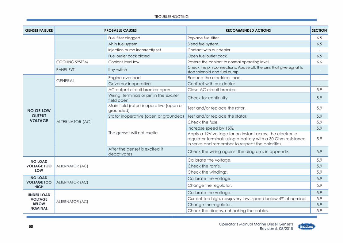
TROUBLESHOOTING
50
Operator’s Manual Marine Diesel Gensets
Revision 6. 08/2018
GENSET FAILURE PROBABLE CAUSES RECOMMENDED ACTIONS SECTION
Fuel filter clogged Replace fuel filter. 6.5
Air in fuel system Bleed fuel system. 6.5
Injection pump incorrectly set Contact with our dealer -
Fuel outlet cock closed Open fuel outlet cock. 6.5
COOLING SYSTEM Coolant level low Restore the coolant to normal operating level. 6.6
PANEL SVT Key switch Check the pin connections. Above all, the pins that give signal to
stop solenoid and fuel pump. -
NO OR LOW
OUTPUT
VOLTAGE
GENERAL Engine overload Reduce the electrical load. -
Governor inoperative Contact with our dealer -
ALTERNATOR (AC)
AC output circuit breaker open Close AC circuit breaker. 5.9
Wiring, terminals or pin in the exciter
field open Check for continuity. 5.9
Main field (rotor) inoperative (open or
grounded) Test and/or replace the rotor. 5.9
Stator inoperative (open or grounded) Test and/or replace the stator. 5.9
The genset will not excite
Check the fuse. 5.9
Increase speed by 15%. 5.9
Apply a 12V voltage for an instant across the electronic
regulator terminals using a battery with a 30 Ohm resistance
in series and remember to respect the polarities.
5.9
After the genset is excited it
deactivates Check the wiring against the diagrams in appendix. 5.9
NO LOAD
VOLTAGE TOO
LOW
ALTERNATOR (AC)
Calibrate the voltage. 5.9
Check the rpm's. 5.9
Check the windings. 5.9
NO LOAD
VOLTAGE TOO
HIGH
ALTERNATOR (AC) Calibrate the voltage. 5.9
Change the regulator. 5.9
UNDER LOAD
VOLTAGE
BELOW
NOMINAL
ALTERNATOR (AC)
Calibrate the voltage. 5.9
Current too high, cosφ very low, speed below 4% of nominal. 5.9
Change the regulator. 5.9
Check the diodes, unhooking the cables. 5.9

TROUBLESHOOTING
51 Operator’s Manual Marine Diesel Gensets
Revision 6. 08/2018
GENSET FAILURE PROBABLE CAUSES RECOMMENDED ACTIONS SECTION
UNDER LOAD
VOLTAGE
ABOVE
NOMINAL
ALTERNATOR (AC)
Calibrate the voltage. 5.9
Change the regulator. 5.9
UNSTABLE
VOLTAGE ALTERNATOR (AC)
Check for uniform rotation. 5.9
Control regulator stability by adjusting potentiometer. 5.9
BLACK SMOKE
FUEL SYSTEM
Fuel filter clogged Change fuel filter. 6.5
Fuel injectors dirty or faulty Clean, test and/or replace the inoperative fuel injector. 6.5
Injection pump incorrectly set Contact with our dealer -
INLET AND EXHAUST SYSTEM Air filter clogged Replace air filter element. 6.7
LOAD GENSET Propeller to large (not enough rpm) The power curve of the genset is not adequate. Carry out a
propulsive power study. -
BLUE SMOKE GENERAL Valve clearance incorrect Adjust the valves. 6.3
LUBRICATION SYSTEM Oil level too high Restore the oil to normal operating level. 6.4
GENSET OVER-
HEATING
GENERAL
Compression weak Check the compression. 6.3
Overload Propeller too large, replace. -
Incorrect injection time Adjust the injection time of the injection pump.
LUBRICATION SYSTEM
Faulty oil pump Contact with our dealer -
Oil viscosity too high Check oil specifications (oil used must be chosen according to
Technical Specifications). 6.4
Oil level too low Restore the oil level. Inspect the genset for oil leaks. 6.4
COOLING SYSTEM
Faulty coolant pump Check coolant pump (impeller, pump sealing). 6.6
Seawater cock clogged or restricted Clean the cock, check the seawater pump impeller for damage. 6.6
Faulty seawater pump Check seawater pump (impeller, pump sealing). 6.6
Water cooler clogged Clean the water cooler and the tube stack fitted in the heat
exchanger. 6.6
Coolant level low Restore the coolant to normal operating level. 6.6
Thermostat inoperative Replace the thermostat. 6.6
INLET AND EXHAUST SYSTEM Air filter clogged Replace air filter. 6.7
LOW OIL
PRESSURE LUBRICATION SYSTEM
Faulty oil pump Contact with our dealer -
Oil pressure relief valve sticking 6.4
Oil pressure too low Check oil level. 6.4

TROUBLESHOOTING
52
Operator’s Manual Marine Diesel Gensets
Revision 6. 08/2018
GENSET FAILURE PROBABLE CAUSES RECOMMENDED ACTIONS SECTION
Oil level too low Restore the oil level. Inspect the genset for oil leaks. 6.4
Faulty oil pressure valve Contact with our dealer -
Faulty oil pressure gauge or switch Check and/or replace oil pressure switch. 6.4
NOISY GENSET GENERAL
Compression weak Check the compression. 6.3
Overload Reduce the electrical load. 6.3
Exhaust system leak Inspect the exhaust system. Replace the inoperative exhaust system
components. 6.3
Vibration excessive Tighten all loose nuts and bolts. 6.3
Valve clearance incorrect Adjust the valves. 6.3
OIL PRESSURE
TOO HIGH LUBRICATION SYSTEM
Oil pressure relief valve sticking Contact with our dealer 6.4
Faulty oil pressure valve Contact with our dealer -
LOW POWER
GENERAL Valve clearance incorrect Contact with our dealer 6.3
FUEL SYSTEM
Fuel filter clogged Contact with our dealer 6.5
Fuel injectors dirty or faulty Contact with our dealer 6.5
Water in fuel system Contact with our dealer 6.5
Fuel injection timing out of adjustment Contact with our dealer 6.5
INLET AND EXHAUST SYSTEM
Air filter clogged Replace air filter element. 6.7
Exhaust backfires Inspect the exhaust system. Replace the inoperative exhaust system
components. 6.7
HIGH FUEL
CONSUMPTION
GENERAL
Compression weak Check the compression. 6.3
Overload Reduce the electrical load. 6.3
Governor inoperative Contact with our dealer -
FUEL SYSTEM Fuel injection timing out of adjustment Adjust the fuel injection timing. 6.5
INLET AND EXHAUST SYSTEM Air filter clogged Replace air filter. 6.7
COOLING SYSTEM Thermostat blocked at open position Replace thermostat and check the coolant state. -
BATTERY
CHARGE
DEFECTIVE
ELECTRICAL SYSTEM (DC)
Battery discharged or dead Recharge or replace the battery. 6.8
Battery connections loose, corroded or
incorrect Verify that the battery connections are correct, clean and tight. 6.8
Governor inoperative Contact with our dealer -
Alternator belt tension Check belt tension and change it if necessary. 6.8

TECHNICAL SPECIFICATIONS
53 Operator’s Manual Marine Diesel Gensets
Revision 6. 08/2018
SECTION 8 – Technical Specifications
8 GTC
10 GTAC
7GSC
8 GSAC
11 GTC
14 GTAC
DIESEL ENGINE
Ge
ne
ral In
form
atio
n
Type Water-cooled, Diesel 4-stroke cycle
Direction of rotation Anti-clokwise observing genset from flywheel side
Nª. Of cylinders – arrangement 3- in line
Allowable Exhaust Back Pressure (KPa) Max- 6,57
Timing Pushrod and rocker arm with gear driven camshaft in
crankcase
Bore (mm) 76 76 78
Stroke (mm) 70 70 92
Total displacement (c.c.) 952 952 1318
Compression ratio 23:1 23: 22:1
Ignition sequence 1-3-2
Adjusting
valve
Inlet Open 18º BTDC 18º BTDC 15º BTDC
Close 46º ABDC 46º ABDC 41º ABDC
Exhaust Open 46º BBDC 46º BBDC 54º BBDC
Close 18º ATDC 18º ATDC 10º ATDC
Inlet and exhaust valve clearance - cold
genset (mm) 0,25
RPM (rpm) 1500 (8 GTC)
1800 (10 GTAC)
1500 (7 GSC)
1800 (8 GSAC)
1500 (11 GTC)
1800 (14 GTAC)
Starting system Glow plugs
Lub
ric
atio
n S
yst
em
System description Forced lubrication by trochoid gear pump
Oil specification Use oil with 15W40 viscosity and no less than ACEA E5/E3 or
API CH-4/SJ quality
Oil pump Trochoid gear type
Oil circuit capacity (l) 4,1 4,1 4,2
Min oil pressure - hot genset (MPa) 0,098 (1,0 kg/cm2)(0,98 bar)
Oil temperature – nominal speed (ºC) 60 - 95
Oil consumption (g/kW) 2,7 2,7 2,7
Fu
el Sy
ste
m
System description
Coolant circulation controlled by centrifugal pump with
thermostatic control and heat exchanger. Cooled exhaust
manifold.
Fuel specifications ASTM diesel fuel No.2-D
Fuel injection pump In-line type
Fuel injection nozzle Throttle type
Co
olin
g S
yst
em
System description
Coolant circulation controlled by centrifugal pump with
thermostatic control and heat exchanger. Cooled exhaust
manifold.
Coolant specifications KRAFFT ACU 2300 CC 50%
Coolant pumps Centrifugal type
Sea water pump Centrifugal type
Coolant circuit capacity (l) 3,5 3,5 6,25
Thermostat valve Start opening + 76.5 ºC
End opening + 90 ºC
Coolant temperature – nominal speed
(ºC) 75 - 85

TECHNICAL SPECIFICATIONS
54 Operator’s Manual Marine Diesel Gensets
Revision 6. 08/2018
8 GTC
10 GTAC
7GSC
8 GSAC
11 GTC
14 GTAC
DIESEL ENGINE
Inle
t a
nd
Exh
au
st
Sy
ste
m
Air supply Air cleaning by means of a dry-type air filter
Exhaust System Cooled exhaust manifold
Dry exhaust manifold (optional equipment)
Ele
ctr
ica
l
Sy
ste
m Voltage – Polarity (V) 12V - ground
Alternator DC (A) 40 40 50
Starter motor (kW) 1,7 1,7 2
ALTERNATOR
Ge
ne
ral In
form
atio
n
Installation type 3-Phase 1-Phase 3-Phase
System cooler Air fresh
Type 4 poles
Protection degree IP23
Excitation system Brushless
Power Factor (cos φ) 0,8 1 0,8
Insulation system H
Voltage variation (V) ± 1
Speed variation (rpm) -5% +3%
GENSET
Ge
ne
ral In
form
atio
n
Active stand-by power (kW) 6,3 (8 GTC)
7,6 (10 GTAC)
6,6 (7 GSC)
8,0 (8 GSAC)
8,4 (11 GTC)
10,9 (14 GTAC)
Apparent stand-by power (kVA) 7,8 (8 GTC)
9,4 (10 GTAC)
6,6 (7 GSC)
8,0 (8 GSAC)
10,5 (11 GTC)
13,6 (14 GTAC)
Voltage (V)
400 / 230
(8 GTC)
480 / 277
(10 GTAC)
230 / 115
(7 GSC)
240 / 120
(8 GSAC)
400 / 230
(11 GTC)
480 / 277
(14 GTAC)
Frequency (Hz) 50 (8 GTC)
60 (10 GTAC)
50 (7 GSC)
60 (8 GSAC)
50 (11 GTC)
60 (14 GTAC)
Current Υ/Δ (A) 12 / 20 29 (7 GSC)
34 (8 GSAC) 17 / 28
Inst
alla
tio
n
Ø Int. Hose, sea water inlet (mm) 20
Ø Int. Hose, diesel fuel inlet (mm) 8
Ø Int. Hose, exhaust outlet (mm) 50
Ø Int. Hose, exhaust outlet cabin (mm) 40 40 50
Air admission displacement -max. rpm
(m3/h) 210-260 210-260 220-280
Minimum battery capacity (Ah) 60 (12V) 60 (12V) 80 (12V)
Length of battery wire (m) ≤ 1,5
Minimal section of battery wire (mm2) 60

TECHNICAL SPECIFICATIONS
55 Operator’s Manual Marine Diesel Gensets
Revision 6. 08/2018
10 GSC
12 GSAC
17 GTC
20 GTAC
14 GSC
17 GSAC
DIESEL ENGINE
Ge
ne
ral In
form
atio
n
Type Water-cooled, Diesel 4-stroke cycle
Direction of rotation Anti-clockwise observing genset from flywheel side
Nº of cylinders – arrangement 3 – in line 4 – in line 4 – in line
Allowable Exhaust Back Pressure (KPa) Max- 6,57
Timing Pushrod and rocker arm with gear driven camshaft in
crankcase
Bore (mm) 78 78 78
Stroke (mm) 92 92 92
Total displacement (c.c.) 1318 1758 1758
Compression ratio 22:1 22:1 22:1
Ignition sequence 1-3-2 1-3-4-2 1-3-4-2
Adjusting
valve
Inlet Open 15º BTDC 15º BTDC 15º BTDC
Close 41º ABDC 41º ABDC 41º ABDC
Exhaust Open 54º BBDC 54º BBDC 54º BBDC
Close 10º ATDC 10º ATDC 10º ATDC
Inlet and exhaust valve clearance - cold
genset (mm) 0,25
RPM (rpm) 1500 (10 GTC)
1800 (12 GTAC)
1500 (17 GSC)
1800 (20 GSAC)
1500 (17 GTC)
1800 (17 GTAC)
Starting system Electric-starter
Lub
ric
atio
n S
yst
em
System description Forced lubrication by trochoid gear pump
Oil specifications Use oil with 15W40 viscosity and no less than ACEA E5/E3 or API
CH-4/SJ quality
Oil pump Trochoid gear type
Oil circuit capacity (l) 4,2 6 6
Min oil pressure – hot genset (MPa) 0,098 (1,0 kg/cm2)(0,98 bar)
Oil temperature – nominal speed (ºC) 60 - 95
Oil comsuption (g/kW) 2,7 2,7 2,7
Fu
el Sy
ste
m
System description Electrical feed pump and mechanical injection pump
Fuel specifications ASTM diesel fuel Nº 2-D
Fuel injection pump In-line type
Fuel injection nozzle Throttle type
Co
olin
g S
yst
em
System description
Coolant circulation controlled by centrifugal pump with
thermostatic control and head exchanger. Cooled exhaust
manifold.
Coolant specifications KRAFFT ACU 2300 CC 50%
Coolant pump Centrifugal type
Sea water pump Centrifugal type
Coolant circuit capacity (l) 6,25 8 8
Thermostat valve
Start opening + 76.5 ºC
End opening + 90 ºC
Coolant temperature – nominal speed
(ºC) 75 - 85

TECHNICAL SPECIFICATIONS
56 Operator’s Manual Marine Diesel Gensets
Revision 6. 08/2018
10 GSC
12 GSAC
17 GTC
20 GTAC
14 GSC
17 GSAC
DIESEL ENGINE
Sis
tem
a
Inle
t a
nd
Exh
au
st
Sy
ste
m
esc
ap
e
Air supple Air cleaning by means of a dry-type air filter
Exhaust System Cooled exhaust manifold Dry exhaust manifold (optional
equipament)
Ele
ctr
ica
l
Sy
ste
m
Voltage – Polarity 12V - ground 12 / 24 (24V is optional) - ground
Alternator DC (A) 50 50 (12V) / 55 (24V)
Starter motor (kW) 2 2 2
ALTERNATOR
Ge
ne
ral In
form
atio
n
Type installation 1-Phase 3-Phase 1-Phase
System cooler Air fresh
Type 4 poles
Protection degree IP23
Excitation system Brushless
Power Factor (cos φ) 1 0,8 1
Insulation system H
Voltage variation (V) ± 1
Speed variation (rpm) -5% +3%
GENSET
Ge
ne
ral In
form
atio
n
Active stand-by power (KW/CV) 9,4 (10 GSC)
12,0 (12 GSAC)
13,2 (17 GTC)
15,6 (20 GTAC)
13,9 (14 GSC)
16,4 (17 GSAC)
Apparent stand-by power (kVA) 9,4 (10 GSC)
12,0 (12 GSAC)
16,4 (17 GTC)
19,5 (20 GTAC)
13,9 (14 GSC)
16,4 (17 GSAC)
Voltage (V)
230 / 115
(10 GSC)
240 / 120
(12 GSAC)
400 / 230
(17 GTC)
480 / 277
(20 GTAC)
230 / 115
(14 GSC)
240 / 120
(17 GSAC)
Frequency (Hz) 50 (10 GSC)
60 (12 GSAC)
50 (17 GTC)
60 (20 GTAC)
50 (14 GSC)
60 (17 GSAC)
Current Υ/Δ (A) 41 (10 GSC)
50 (12 GSAC) 24/41
61 (14 GSC)
69 (17 GSAC)
Inst
alla
tio
n
Ø Int. Hose, sea water inlet (mm) 20
Ø Int. Hose, diesel fuel inlet (mm) 8
Ø Int. Hose, exhaust outlet (mm) 50
Ø Int. Hose, exhaust outlet cabin (mm) 50
Air admission displacement-max. rpm
(m3/h) 220-280 240-300 240-300
Minimum battery capacity (Ah) 80 (12V) 80 (12V) / TBD (24V) 80 (12V) / TBD (24V)
Length ob battery wire (m) ≤ 1,5
Minimal section of battery wire (mm2) 60

TIGHTENING TORQUES
57 Operator’s Manual Marine Diesel Gensets
Revision 6. 08/2018
SECTION 9 – Tightening Torques
Important nuts and screws.
TIGHTENING VALUES THREAD 7 GTC / 10 GTAC / 7 GSC / 8 GSAC
N· m (kgf· m)
Cylinder head M10 73.5 a 83.4 (7.5 a 8.5)
Rocker arm cover M6 4.9 a 6.9 (0.5 a 0.7)
Crankshaft pulley M16 98.1 a 117.7 (10.0 a 12.0)
Main bearing caps M10 49.0 a 53.p (5.0 a 5.5)
Coupling rod caps M8 31.4 a 34.3 (3.2 a 3.5)
Flywheel M10 83.4 a 93.2 (8.5 a 9.5)
Drain plug, oil pan M18 9.0 a 58.8 (5.0 a 6.0)
Oil filter M20 10.8 a 12.7 (1.1 a 1.3)
Oil pressure relief valve M18 39.2 a 49.0 (4.0 a 5.0)
Fuel injection pipes M20 49.0 a 58.8 (5.0 a 6.0)
Glow plug M10 14.7 a 19.6 (1.5 a 2.0)
General tightening torque
M6
M8
M10
7T
7.85 a 9.80 (0.8 a 1.0)
14.7 a 21.6 (1.5 a 2.2)
29.4 a 41.2 (3.0 a 4.2)
TIGHTENING VALUES THREAD
10 GSC / 12 GSAC / 11 GTC / 14 GTAC / 14 GSC
/ 17 GSAC / 17 GTC / 20 GTAC
N· m (kgf· m)
Cylinder head M10 83.0 a 93.0 (8.5 a 9.5)
Rocker arm cover M8 9.8 a 12.8 (1.0 a 1.3)
Support shaft of rocker
arm M8 14.2 a 15.2 (1.0 a 2.0)
Crankshaft pulley M18 147.0 a 197.0 (15.0 a 20.0)
Main bearing caps M10 49.0 a 54.0 (5.0 a 5.5)
Coupling rod caps M9 32.3 a 37.3 (3.3 a 3.8)
Flywheel M12 127.0 a 138.0 (13.0 a 14.0)
Drain plug, oil pan M14 34.0 a 44.0 (3.5 a 4.5)
Oil filter M20 11 a 13 (1.1 a 1.3)
Oil pressure relief valve M22 44.0 a 54.0 (4.5 a 5.5)
Fuel injection pipes M20 49.0 a 59.0 (5.0 a 6.0)
Glow plug M10 14.7 a 19.7 (1.5 a 2.0)
Nut for starter terminal B+ M8 9.8 a 11.8 (1.0 a 1.2)
General tightening torque
M6
M8
M10
M12
M14
4T 7T
2.9 a 4.9 (0.3 a 0.5)
9.8 a 11.8 (1.0 a 1.2)
18.0 a 24.0 (1.8 a 2.5)
29.3 a 41.3 (3.0 a 4.2)
49.0 a 69.0 (5.0 a 7.0)
7.8 a 9.8 (0.8 a 1.0)
15 a 21 (1.5 a 2.2)
29.3 a 41.3 (3.0 a 4.2)
53.7 a 73.7 (5.5 a 7.5)
78.2 a 108.2 (8.0 a 11.0)

TECHNICAL APPENDICES
58 Operator’s Manual Marine Diesel Gensets
Revision 6. 08/2018
SECTION 10 – Technical Appendices
TECHNICAL APPENDICES
59 Operator’s Manual Marine Diesel Gensets
Revision 6. 08/2018
10.1. Wiring diagrams
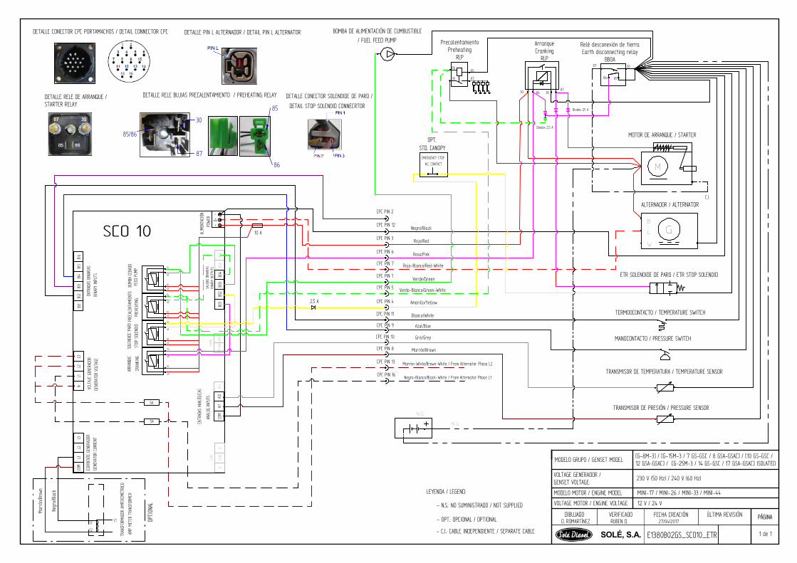
DIBUJADO VERIFICADO FECHA CREACIÓN ÚLTIMA REVISIÓN
SOLÉ, S.A.RUBEN D.D. ROMARTÍNEZ 27/04/2017
PÁGINA
1 de 1E1380B02GS_SCO10_ETR
LEYENDA / LEGEND:
- N.S.: NO SUMINISTRADO / NOT SUPPLIED
- OPT.: OPCIONAL / OPTIONAL
MODELO MOTOR / ENGINE MODEL:
VOLTAGE MOTOR / ENGINE VOLTAGE:
VOLTAGE GENERADOR /GENSET VOLTAGE:
230 V (50 Hz) / 240 V (60 Hz)
MINI-17 / MINI-26 / MINI-33 / MINI-44
12 V / 24 V
MODELO GRUPO / GENSET MODEL: [G-8M-3] / [G-15M-3 / 7 GS-GSC / 8 GSA-GSAC] / [10 GS-GSC /12 GSA-GSAC] / [G-25M-3 / 14 GS-GSC / 17 GSA-GSAC] ISOLATED
- C.I.: CABLE INDEPENDIENTE / SEPARATE CABLE
CRAN
KING
2.5 A
BI6
BI5
BI4
BI3
BI2
BI1
BINA
RY O
UTPU
TS
5A
5A
8785
8630
BINA
RY IN
PUTS
GENE
RATO
R VO
LTAG
E
N
D+
L2
-+PO
WER
RPM
ANAL
OG IN
PUTS
CAN
GENE
RATO
R CU
RREN
T
AI1
HH
COM
AI3
AI2
COM
RPM
GND
RPM
IN
COM
BO1
L2
BO6
BO5
BO4
BO3
BO2
L3L1
L3L1
STOP
SOL
ENOI
DPR
EHEA
TING
FEED
PUM
PAR
RANQ
UESO
LENO
IDE
PARO
PREC
ALEN
TAMI
ENTO
BOMB
A CE
BADO
ENTR
ADAS
BIN
ARIA
SVO
LTAJ
E GE
NERA
DOR
CORR
IENT
E GE
NERA
DOR
ENTR
ADAS
ANA
LÓGI
CAS
SALID
AS B
INAR
IAS
ALIM
ENTA
CIÓN
10 A
85/86
30
87
85
86
SCO 10
L1
Marr
ón/B
rown
Negr
o/Bl
ack
S1
S2
TRAN
SFOR
MADO
R AM
PERO
MÉTR
ICO
AMP
METE
R TR
ANSF
ORME
R
8785
8630
8785
8630
8785
8630
DETALLE RELE DE ARRANQUE /STARTER RELAY
DETALLE RELE BUJIAS PRECALENTAMIENTO / PREHEATING RELAY
DETALLE CONECTOR CPC PORTAMACHOS / DETAIL CONNECTOR CPC DETALLE PIN L ALTERNADOR / DETAIL PIN L ALTERNATOR
DETALLE CONECTOR SOLENOIDE DE PARO /
DETAIL STOP SOLENOID CONNECRTOR
CPC PIN 2
CPC PIN 12
CPC PIN 3
CPC PIN 6
CPC PIN 7
CPC PIN 1
CPC PIN 5
CPC PIN 4
CPC PIN 11
CPC PIN 9
CPC PIN 10
CPC PIN 8
CPC PIN 13
CPC PIN 16
N.S.
N.S.
M
GL
B
W
Negro/Black
Rojo/Red
Rosa/Pink
Rojo-Blanco/Red-White
Verde-Blanco/Green-White
Amarillo/Yellow
Blanco/White
Azul/Blue
Gris/Grey
Marrón/Brown
ArranqueCranking
RLP
PrecalentamientoPreheating
RLP
Relé desconexión de tierraEarth disconnecting relay
BB0A
C.I.
TRANSMISOR DE PRESIÓN / PRESSURE SENSOR
TRANSMISOR DE TEMPERATURA / TEMPERATURE SENSOR
MANOCONTACTO / PRESSURE SWITCH
TERMOOCONTACTO / TEMPERATURE SWITCH
ETR SOLENOIDE DE PARO / ETR STOP SOLENOID
EMERGENCY STOP
OPT.STD. CANOPY
N.C. CONTACT
Diodos 25 A
Diodos 2,5 A
Marrón-White/Brown-White / From Alternator Phase L2
Negro-Blanco/Black-White / From Alternator Phase L1
BOMBA DE ALIMENTACIÓN DE CUMBUSTIBLE/ FUEL FEED PUMP
Verde/Green
MOTOR DE ARRANQUE / STARTER
ALTERNADOR / ALTERNATOR
30 8586
87
87
8586
30
30
8685
87
OPTI
ONAL

DIBUJADO VERIFICADO FECHA CREACIÓN ÚLTIMA REVISIÓN
SOLÉ, S.A.RUBEN D.D. ROMARTÍNEZ 27/04/2017
PÁGINA
1 de 1E1380B02GT_SCO10_ETR
LEYENDA / LEGEND:
- N.S.: NO SUMINISTRADO / NOT SUPPLIED
- OPT.: OPCIONAL / OPTIONAL
MODELO MOTOR / ENGINE MODEL:
VOLTAGE MOTOR / ENGINE VOLTAGE:
VOLTAGE GENERADOR /GENSET VOLTAGE:
400/230 V (50 Hz) / 480/277 V (60 Hz)
MINI-17 / MINI-26 / MINI-33 / MINI-44
12 V / 24 V
MODELO GRUPO / GENSET MODEL: [G-8T-3] / [G-15T-3 / 8 GT-GTC / 10 GTA-GTAC] / [11 GT-GTC / 14GTA-GTAC] / [G-25T-3 / 17 GT-GTC / 20 GTA-GTAC] ISOLATED
- C.I.: CABLE INDEPENDIENTE / SEPARATE CABLE
85/86 30
87
85
86
DETALLE RELE DE ARRANQUE /STARTER RELAY
DETALLE RELE BUJIAS PRECALENTAMIENTO / PREHEATING RELAY
DETALLE CONECTOR CPC PORTAMACHOS / DETAIL CONNECTOR CPCDETALLE PIN L ALTERNADOR / DETALLE CONECTOR SOLENOIDE DE PARO /
DETAIL STOP SOLENOID CONNECRTOR
CPC PIN 2
CPC PIN 12
CPC PIN 3
CPC PIN 6
CPC PIN 7
CPC PIN 1
CPC PIN 5
CPC PIN 4
CPC PIN 11
CPC PIN 9
CPC PIN 10
CPC PIN 8
N.S.
N.S.
M
GL
B
W
Negro/Black
Rojo/Red
Rosa/Pink
Rojo-Blanco/Red-White
Verde-Blanco/Green-White
Amarillo/Yellow
Blanco/White
Azul/Blue
Gris/Grey
Marrón/Brown
ArranqueCranking
RLP
PrecalentamientoPreheating
RLP
Relé desconexión de tierraEarth disconnecting relay
BB0A
C.I.
TRANSMISOR DE PRESIÓN / PRESSURE SENSOR
TRANSMISOR DE TEMPERATURA / TEMPERATURE SENSOR
MANOCONTACTO / PRESSURE SWITCH
TERMOOCONTACTO / TEMPERATURE SWITCH
ETR SOLENOIDE DE PARO / ETR STOP SOLENOID
EMERGENCY STOP
OPT.STD. CANOPY
N.C. CONTACT
Diodos 25 A
Diodos 2,5 A
BOMBA DE ALIMENTACIÓN DE CUMBUSTIBLE/ FUEL FEED PUMP
Verde/Green
MOTOR DE ARRANQUE / STARTER
ALTERNADOR / ALTERNATOR
30 8586
87
87
8586
30
30
8685
87
CRAN
KING
2.5 A
BI6
BI5
BI4
BI3
BI2
BI1
BINA
RY O
UTPU
TS
5A
8785
8630
BINA
RY IN
PUTS
GENE
RATO
R VO
LTAG
E
N
D+
L2
-+PO
WER
RPM
ANAL
OG IN
PUTS
CAN
GENE
RATO
R CU
RREN
T
AI1
HH
COM
AI3
AI2
COM
RPM
GND
RPM
IN
COM
BO1
L2
BO6
BO5
BO4
BO3
BO2
L3L1
L3L1
STOP
SOL
ENOI
DPR
EHEA
TING
FEED
PUM
PAR
RANQ
UESO
LENO
IDE
PARO
PREC
ALEN
TAMI
ENTO
BOMB
A CE
BADO
ENTR
ADAS
BIN
ARIA
SVO
LTAJ
E GE
NERA
DOR
CORR
IENT
E GE
NERA
DOR
ENTR
ADAS
ANA
LÓGI
CAS
SALID
AS B
INAR
IAS
ALIM
ENTA
CIÓN
10 ASCO 10
L1
Marr
ón/B
rown
Negr
o/Bl
ack
S1
S2
TRAN
SFOR
MADO
R AM
PERO
MÉTR
ICO
AMP
METE
R TR
ANSF
ORME
R
8785
8630
8785
8630
8785
8630
5A
5A
L2S1
S2
L3S1
S2
Azul/Blue
Gris/
Grey
Marrón-White/Brown-White / From alternator Phase l2
Negro-Blanco/Black-White / From alternator Phase L1
CPC PIN 13
CPC PIN 16
Azul-White/Blue-White / From alternator Neutral-Point
Gris-Blanco/Grey-White / From alternator Phase L3
CPC PIN 14
CPC PIN 15
OPTI
ONAL
DETAIL PIN L ALTERNATOR

DIBUJADO VERIFICADO FECHA CREACIÓN ÚLTIMA REVISIÓN
SOLÉ, S.A.RUBEN D.D. ROMARTÍNEZ 21/04/2017
PÁGINA
1 de 1E1380E02GS_SCO10_ETR
LEYENDA / LEGEND:
- N.S.: NO SUMINISTRADO / NOT SUPPLIED
- OPT.: OPCIONAL / OPTIONAL
MODELO MOTOR / ENGINE MODEL:
VOLTAGE MOTOR / ENGINE VOLTAGE:
VOLTAGE GENERADOR /GENSET VOLTAGE:
230 V (50 Hz) / 240 V (60 Hz)
MINI-17 / MINI-26 / MINI-33 / MINI-44
12 V / 24 V
MODELO GRUPO / GENSET MODEL: [G-8M-3(X)] / [G-15M-3 / 7 GS-GSC / 8 GSA-GSAC] / [10 GS-GSC/ 12 GSA-GSAC] / [G-25M-3 / 14 GS-GSC / 17 GSA-GSAC]
Negro/Black
Rojo/Red
Rosa/Pink
Rojo-Blanco/Red-White
Verde/Green
Verde-Blanco/Green-White
Amarillo/Yellow
Blanco/White
Azul/Blue
Gris/Grey
Marrón/Brown
Marrón-White/Brown-White / From alternator Phase l2
Negro-Blanco/Black-White / From alternator Phase L1
TRANSMISOR DE PRESIÓN / PRESSURE SENSOR
TRANSMISOR DE TEMPERATURA / TEMPERATURE SENSOR
MANOCONTACTO / PRESSURE SWITCH
TERMOOCONTACTO / TEMPERATURE SWITCH
ETR SOLENOIDE DE PARO / ETR STOP SOLENOID
N.S.
N.S.
M
GD
B
W
NGK
PRECALENTAMIENTO / PREHEATING
30
8586
87
PARO DE EMERGENCIAEMERGENCY STOP
OPT.STD. CANOPY
N.C. CONTACT
Diodos 25 A
BOMBA DE ALIMENTACIÓN DE CUMBUSTIBLE /
FUEL FEED PUMP
CPC PIN 2
CRAN
KING
2.5 A
BI6
BI5
BI4
BI3
BI2
BI1
BINA
RY O
UTPU
TS
5A
5A
8785
8630
BINA
RY IN
PUTS
GENE
RATO
R VO
LTAG
E
N
D+
L2
-+PO
WER
RPM
ANAL
OG IN
PUTS
CAN
GENE
RATO
R CU
RREN
T
AI1
HH
COM
AI3
AI2
COM
RPM
GND
RPM
IN
COM
BO1
L2
BO6
BO5
BO4
BO3
BO2
L3L1
L3L1
STOP
SOL
ENOI
DPR
EHEA
TING
FEED
PUM
PAR
RANQ
UESO
LENO
IDE
PARO
PREC
ALEN
TAMI
ENTO
BOMB
A CE
BADO
ENTR
ADAS
BIN
ARIA
SVO
LTAJ
E GE
NERA
DOR
CORR
IENT
E GE
NERA
DOR
ENTR
ADAS
ANA
LÓGI
CAS
SALID
AS B
INAR
IAS
ALIM
ENTA
CIÓN
CPC PIN 12
CPC PIN 3
CPC PIN 6
CPC PIN 7
CPC PIN 1
CPC PIN 5
CPC PIN 4
CPC PIN 11
CPC PIN 9
CPC PIN 10
CPC PIN 8
CPC PIN 13
CPC PIN 16
10 A
85/86 30
87
85
86MOTOR DE ARRANQUE / STARTER
ALTERNADOR / ALTERNATOR
30 8586 87
ARRANQUE / CRANKINGRLP
SCO 10
L1
Marr
ón/B
rown
Negr
o/Bl
ack
S1
S2
TRAN
SFOR
MADO
R AM
PERO
MÉTR
ICO
AMP
METE
R TR
ANSF
ORME
R
8785
8630
8785
8630
8785
8630
DETALLE RELE DE ARRANQUE /STARTER RELAY
DETALLE RELE BUJIAS PRECALENTAMIENTO / PREHEATING RELAY
DETALLE CONECTOR CPC PORTAMACHOS / DETAIL CONNECTOR CPC DETALLE PIN L ALTERNADOR / DETAIL PIN L ALTERNATOR
DETALLE CONECTOR SOLENOIDE DE PARO /
DETAIL STOP SOLENOID CONNECRTOR
OPTI
ONAL

DIBUJADO VERIFICADO FECHA CREACIÓN ÚLTIMA REVISIÓN
SOLÉ, S.A.RUBEN D.D. ROMARTÍNEZ 24/04/2017
PÁGINA
1 de 1E1380E02GT_SCO10_ETR
LEYENDA / LEGEND:
- N.S.: NO SUMINISTRADO / NOT SUPPLIED
- OPT.: OPCIONAL / OPTIONAL
MODELO MOTOR / ENGINE MODEL:
VOLTAGE MOTOR / ENGINE VOLTAGE:
VOLTAGE GENERADOR /GENSET VOLTAGE:
400/230 V (50 Hz) / 480/277 V (60 Hz)
MINI-17 / MINI-26 / MINI-33 / MINI-44
12 V / 24 V
MODELO GRUPO / GENSET MODEL: [G-8T-3] / [G-15T-3 / 8 GT-GTC / 10 GTA-GTAC] / [11 GT-GTC /14 GTA-GTAC] / [G-25T-3 / 17 GT-GTC / 20 GTA-GTAC]
Negro/Black
Rojo/Red
Rosa/Pink
Rojo-Blanco/Red-White
Verde/Green
Verde-Blanco/Green-White
Amarillo/Yellow
Blanco/White
Azul/Blue
Gris/Grey
Marrón/Brown
Marrón-White/Brown-White / From alternator Phase l2
Negro-Blanco/Black-White / From alternator Phase L1
TRANSMISOR DE PRESIÓN / PRESSURE SENSOR
TRANSMISOR DE TEMPERATURA / TEMPERATURE SENSOR
MANOCONTACTO / PRESSURE SWITCH
TERMOOCONTACTO / TEMPERATURE SWITCH
ETR SOLENOIDE DE PARO / ETR STOP SOLENOID
N.S.
N.S.
M
GD
B
W
NGK
PRECALENTAMIENTO / PREHEATING
30
8586
87
PARO DE EMERGENCIAEMERGENCY STOP
OPT.STD. CANOPY
N.C. CONTACT
Diodos 25 A
BOMBA DE ALIMENTACIÓN DE CUMBUSTIBLE /
FUEL FEED PUMP
CPC PIN 2
CRAN
KING
2.5 A
BI6
BI5
BI4
BI3
BI2
BI1
BINA
RY O
UTPU
TS
5A
8785
8630
BINA
RY IN
PUTS
GENE
RATO
R VO
LTAG
E
N
D+
L2
-+PO
WER
RPM
ANAL
OG IN
PUTS
CAN
GENE
RATO
R CU
RREN
T
AI1
HH
COM
AI3
AI2
COM
RPM
GND
RPM
IN
COM
BO1
L2
BO6
BO5
BO4
BO3
BO2
L3L1
L3L1
STOP
SOL
ENOI
DPR
EHEA
TING
FEED
PUM
PAR
RANQ
UESO
LENO
IDE
PARO
PREC
ALEN
TAMI
ENTO
BOMB
A CE
BADO
ENTR
ADAS
BIN
ARIA
SVO
LTAJ
E GE
NERA
DOR
CORR
IENT
E GE
NERA
DOR
ENTR
ADAS
ANA
LÓGI
CAS
SALID
AS B
INAR
IAS
ALIM
ENTA
CIÓN
CPC PIN 12
CPC PIN 3
CPC PIN 6
CPC PIN 7
CPC PIN 1
CPC PIN 5
CPC PIN 4
CPC PIN 11
CPC PIN 9
CPC PIN 10
CPC PIN 8
CPC PIN 13
CPC PIN 16
10 A
85/86 30
87
85
86MOTOR DE ARRANQUE / STARTER
ALTERNADOR / ALTERNATOR
30 8586 87
ARRANQUE / CRANKINGRLP
SCO 10
L1
Marr
ón/B
rown
Negr
o/Bl
ack
S1
S2
TRAN
SFOR
MADO
R AM
PERO
MÉTR
ICO
AMP
METE
R TR
ANSF
ORME
R
8785
8630
8785
8630
8785
8630
DETALLE RELE DE ARRANQUE /STARTER RELAY
DETALLE RELE BUJIAS PRECALENTAMIENTO / PREHEATING RELAY
DETALLE CONECTOR CPC PORTAMACHOS / DETAIL CONNECTOR CPC DETALLE PIN L ALTERNADOR / DETAIL PIN L ALTERNATOR
DETALLE CONECTOR SOLENOIDE DE PARO /
DETAIL STOP SOLENOID CONNECRTOR
Azul-White/Blue-White / From alternator Neutral-Point
Gris-Blanco/Grey-White / From alternator Phase L3
CPC PIN 14
CPC PIN 15
5A
5A
L2S1
S2
L3S1
S2
Azul/Blue
Gris/
Grey
OPTI
ONAL
TECHNICAL APPENDICES
64 Operator’s Manual Marine Diesel Gensets
Revision 6. 08/2018
10.2. Alternator connections

COLLEGAMENTO - CONNECTIONS - CONNEXION - ANSCHLUSS - CONEXIÓN12 morsetti - 12 wires - 12 klemmen - 12 bornes - 12 bornes
82

COLLEGAMENTO - CONNECTIONS - CONNEXION - ANSCHLUSS - CONEXIÓNMONOFASE - SINGLE-PHASE - MONOPHASÉ - EINPHASIG - MONOFÁSICO
TECHNICAL APPENDICES
67 Operator’s Manual Marine Diesel Gensets
Revision 6. 08/2018
10.3. Regulator connections

TECHNICAL APPENDICES
68 Operator’s Manual Marine Diesel Gensets
Revision 6. 08/2018
TensiónV EstabilidadST
RegulacióndelasubvelocidadUF
Alimentación EstatorExcitador
BL4-U
RegulacióndelaFrecuencia
incremento de tensión
reducción de tensión
incremento del límite de de la subvelocidad
reducción de la estabilidad
incremento de la estabilidad
reducción del límite de de la subvelocidad Conexion con un controlador,
observar la polaridad:

TECHNICAL APPENDICES
69 Operator’s Manual Marine Diesel Gensets
Revision 6. 08/2018
10.4. Overall dimensions

DIBUJADO VERIFICADO GRADOPRECISIÓN FECHA CREACIÓN ÚLTIMA REVISIÓN
MATERIAL TRATAMIENTO ESCALAPRESENTACIÓNACABADO
Basto
±0.2
±0.5
±0.8
SOLÉ, S.A.
±1.2
Medio
±0.1
±0.2
±0.3
±0.5
Fin
o±0.0
5±0.1
±0.1
5±0.2
Gra
do
de
Pre
cis
ión
DIN
-7168
0 a 6
6 a 30
30 a
10
0
100
a300
Med
idas
No
min
ale
s(m
m)
8 GTC / 10 GTAC / 7 GSC / 8 GSAC GENSET
JOSE S.UBACH MEDIO ---28/09/2012
48 816 28
892
35
1.5
62
106 105
161
105.5
106.5 104.5
176.5
112
112
608
18
BATTERY CONNECTIONS
SEA WATER INLET (Ø20)
EMERGENCY STOP
GENERATOR AIR INLET
CUSTOMER PANELCONNECTION
AC BREAKER
FIRE EXTINGUISHERACCESS HOLE
AIR OUTLET
EQUIPMENT GROUNDCONNECTION
FUEL INLET (Ø8)FUEL OUTLET (Ø6)
90
380
14
6.5
90
560
605
CUSTOMER LOADLEAD ACCES
WET EXHAUSTOUTLET (Ø40)
VIEW A
VIEW DVIEW C
VIEW ESIPHON BREAK CONNECTIONS(AIR VENT SYSTEM - OPTIONAL KIT)
LEAKS COOLANTOUTLET
SEA WATER OUTLET (Ø20)(ONLY DRY EXHAUST)
4 x Ø16 MOUNTING HOLES
SIPHON BREAK CONNECTIONS(AIR VENT SYSTEM - OPTIONAL KIT)
(USE ONLY FOR A REFERENCE)
Note: Dimensions inmillimeters
VIEW B
A
E
C
D
B

DIBUJADO VERIFICADO GRADOPRECISIÓN FECHA CREACIÓN ÚLTIMA REVISIÓN
MATERIAL TRATAMIENTO ESCALAPRESENTACIÓNACABADO
Basto
±0.2
±0.5
±0.8
SOLÉ, S.A.
±1.2
Medio
±0.1
±0.2
±0.3
±0.5
Fin
o±0.0
5±0.1
±0.1
5±0.2
Gra
do
de
Pre
cis
ión
DIN
-716
8
0 a 6
6 a 30
30 a
100
100
a300
Med
idas
No
min
ale
s(m
m)
11 GTC / 14 GTAC / 10 GSC / 12 GSAC
I.BELLIDO S.UBACH MEDIO 03/10/2012
(USE ONLY FOR A REFERENCE)
Note: Dimensions in millimeters
VIEW A
11
1.5
145.5
BATTERY CONNECTIONS
SEA WATER INLET (Ø20)
EMERGENCY STOP
FUEL INLET (Ø8)
CUSTOMER PANELCONNECTION
AC BREAKERSTAR/STOP SWITCH
FIRE EXTINGUISHERACCESS HOLE
LEAKS COOLANTOUTLET (Ø8)
CUSTOMER LOADLEAD ACCESS
EQUIPMENT GROUNDCONNECTION
VIEW DVIEW C
VIEW E106 130 387.5 225 107.5
62
37
1.5
14
6.5
FUEL OUTLET (Ø8)
48 956 28
1032
161
105.5
400
400
580
8 x Ø16 MOUNTING HOLES
SEA WATER OUTLET (Ø20)(ONLY DRY EXHAUST)
E
D
B
C
A
VIEW B
4895628
1032
SIPHON BREAK CONNECTIONS(AIR VENT SYSTEM - OPTIONAL KIT)
AIR OUTLET
GENERATOR AIR INLET
18
668


INSPECTION PRIOR TO THE DELIVERY OF PROPULSION ENGINES
73 Operator’s Manual Marine Diesel Gensets
Revision 6. 08/2018
SECTION 11 - Instructions to Replace and Remove
When you decide to replace the genset, please contact SOLÉ DIESELS.A.; will provide
relevant instructions regarding the laws in force at the time. When disposing of the whole or parts
of this genset, meets LAWS IN FORCE IN THE COUNTRY OF INSTALLATION.
For more information about the materials they are made of the individual components of
the generator, contact SOLÉ DIESEL S.A.

INSTRUCTIONS TO REPLACE AND REMOVE
74 Operator’s Manual Marine Diesel Gensets
Revision 6. 08/2018
mmmmmmYES SÍNO NO
V/x
V/x
Water, oil and fuel leaks in the engine.
Type of electrical installation: Total power consumption:
Angle of the generator set (boat moored):
belowaboveIs the wet exhaust elbow above or below the floating line?Maximum angle of the generator set (navigation conditions)
Verify the control panel:indications and alamar operation.
Bledd the fresh waater cooling system.
Verification of Generator Set Nº-Load Operation NotesOil pressure
Airtight water cock
Electrical installation connections.Engine oil levelCoolant level and concentration.Control panel operation.Transmission belts and belt tension.
Verifications Pior to Start-Up NotesCorrect engine alignment.
Has an exhaust collector been installed? Has an air trap been installed?
Int. Diameter of sea water intake to the pump mmInt. Diameter of exhaust hose (if applicable):Int. Diameter of diesel intake:Int. Diameter of diesel return intake
Echaust, Cooling and Fuel Line Information
INSPECIONS PRIOR TO THE DELIVERY OF GENERATOR SETSInstaller / Marina information
Owner's Information
Generator Set Information
Installation Information
Generator set model:Generator set serial number: Alternator serial nº. (if applicable):
Machine chamber operating temperature:
Installation Date:E-mail:
Email:
Installer Company:Contact Tel. no.:
Name and surnames:Contact Tel. no.:
V/x
V/x
Verify the electrical power and voltage of the generator set at full load.
Engine output and alternator operation at variable loat.Engine temperature and oil pressure.
Verification of Generator Set Operations with Load Notes
Review of the generator set instructions manual.Study the generator set control panel functions.
Information for the Ownre Observaciones
Delivery of the instructions manual and generator set-related documents.
Report the maintenace schedule indicated in the manuals.Report the first revision date.

MAINTENANCE LOG
75 Operator’s Manual Marine Diesel Gensets
Revision 6. 08/2018
MAINTENANCE LOG
DATE HOURS DESCRIPTION SERVICE NAME

INSTRUCTIONS TO REPLACE AND REMOVE
76 Operator’s Manual Marine Diesel Gensets
Revision 6. 08/2018
DATE HOURS DESCRIPTION SERVICE NAME

MAINTENANCE LOG
77 Operator’s Manual Marine Diesel Gensets
Revision 6. 08/2018

INSTRUCTIONS TO REPLACE AND REMOVE
78 Operator’s Manual Marine Diesel Gensets
Revision 6. 08/2018
U_ GBAV_EN
Rev. 6