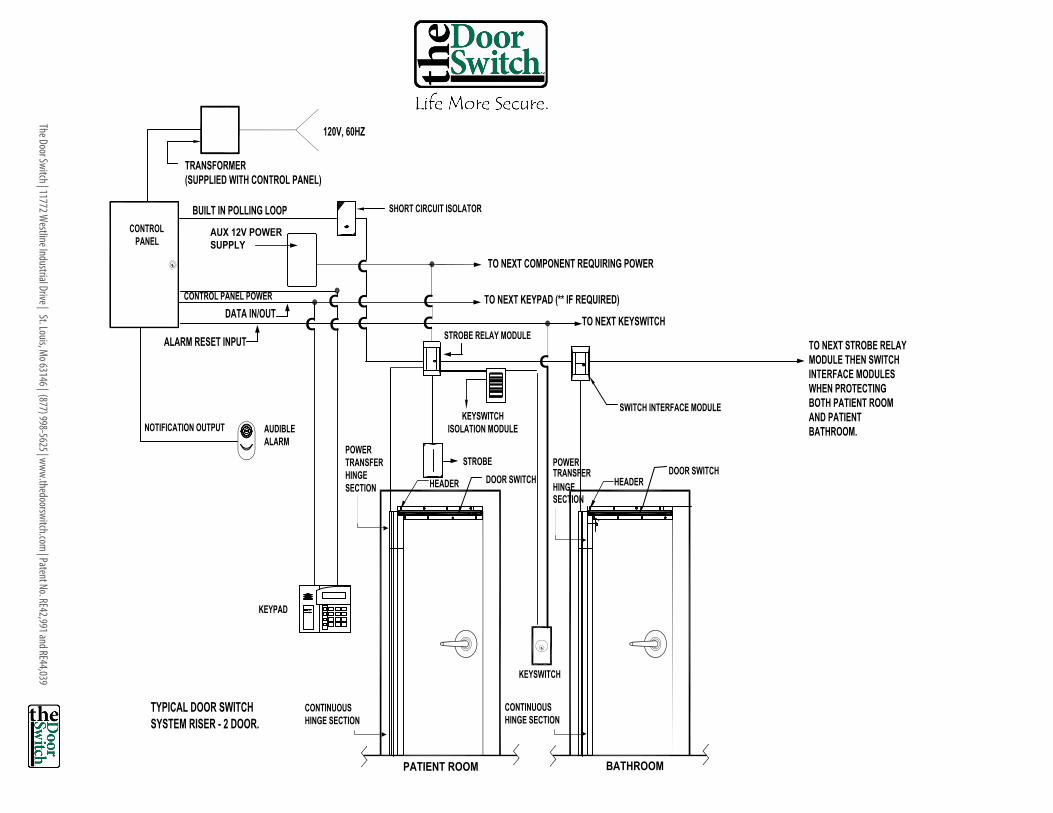
typical door switch system riser
TRANSCRIPT
The Door Switch | 11772 Westline Industrial Drive | St. Louis, M
o 63146 | (877) 998-5625 | www.thedoorswitch.com | Patent No. RE42,991 and RE44,039
CONTINUOUS HINGE SECTION
PATIENT ROOM BATHROOM
POWERTRANSFERHINGESECTION
DOOR SWITCH
SWITCH INTERFACE MODULE
TO NEXT COMPONENT REQUIRING POWER
TO NEXT KEYPAD (** IF REQUIRED)
STROBE RELAY MODULE
STROBE
SHORT CIRCUIT ISOLATOR
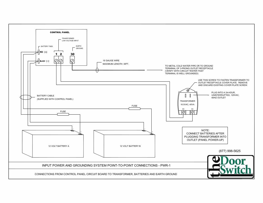
TRANSFORMER(SUPPLIED WITH CONTROL PANEL)
TYPICAL DOOR SWITCH SYSTEM RISER - 2 DOOR.
KEYPAD
KEYSWITCH
AUDIBLEALARM
CONTROL PANEL
BUILT IN POLLING LOOP
NOTIFICATION OUTPUTKEYSWITCH
ISOLATION MODULE
TO NEXT KEYSWITCH DATA IN/OUT
ALARM RESET INPUT
120V, 60HZ
TO NEXT STROBE RELAY MODULE THEN SWITCH INTERFACE MODULES WHEN PROTECTING BOTH PATIENT ROOM AND PATIENT BATHROOM.
C
C
CCC
C
C
AUX 12V POWER SUPPLY
CONTINUOUS HINGE SECTION
POWERTRANSFERHINGESECTION
CCCONTROL PANEL POWER
DOOR SWITCHHEADER HEADER


— 6
9 —
VIS
TA
-12
8B
PT
Su
mm
ary
of C
on
ne
ctio
ns
Dia
gra
m
V128BPT-SOC-V1
+ +-
N.C. N.C.
N.O.
2k EOLR (note 1)
2k EOLR (note 1)
+ -
+ -
+ -BELL
SIREN
NO
CO
NN
EC
TIO
N
TRANSFORMER 16.5VAC, 40VA
ADEMCO No.1361 (IN CANADA
USE No. 1361CN) or 1361X10 IF X-10 DEVICES WILL BE USED
Connect to 24hr. 120VAC, 60 Hz Outlet
Red Blk Grn Yel
REMOTE KEYPAD 6160
(Addressable keypad) only
+ +-N.C. N.C.
2k EOLR (note 1)
2k EOLR (note 1)
+ +-
N.C.
+ +-
N.C.N.C.
2k EOLR (note 1,4)
TIP
(B
RO
WN
)R
ING
(G
RA
Y)
TIP
(G
RE
EN
)R
ING
(R
ED
)
Handset Incoming Phone Line
Telephone connections using Ademco No. 620 RJ31X direct connect
cord.
EARTH GROUND Connect to good earth ground to maintain im- munity to transients. See Instructions for proper grounding.
SMOKE
4190SN
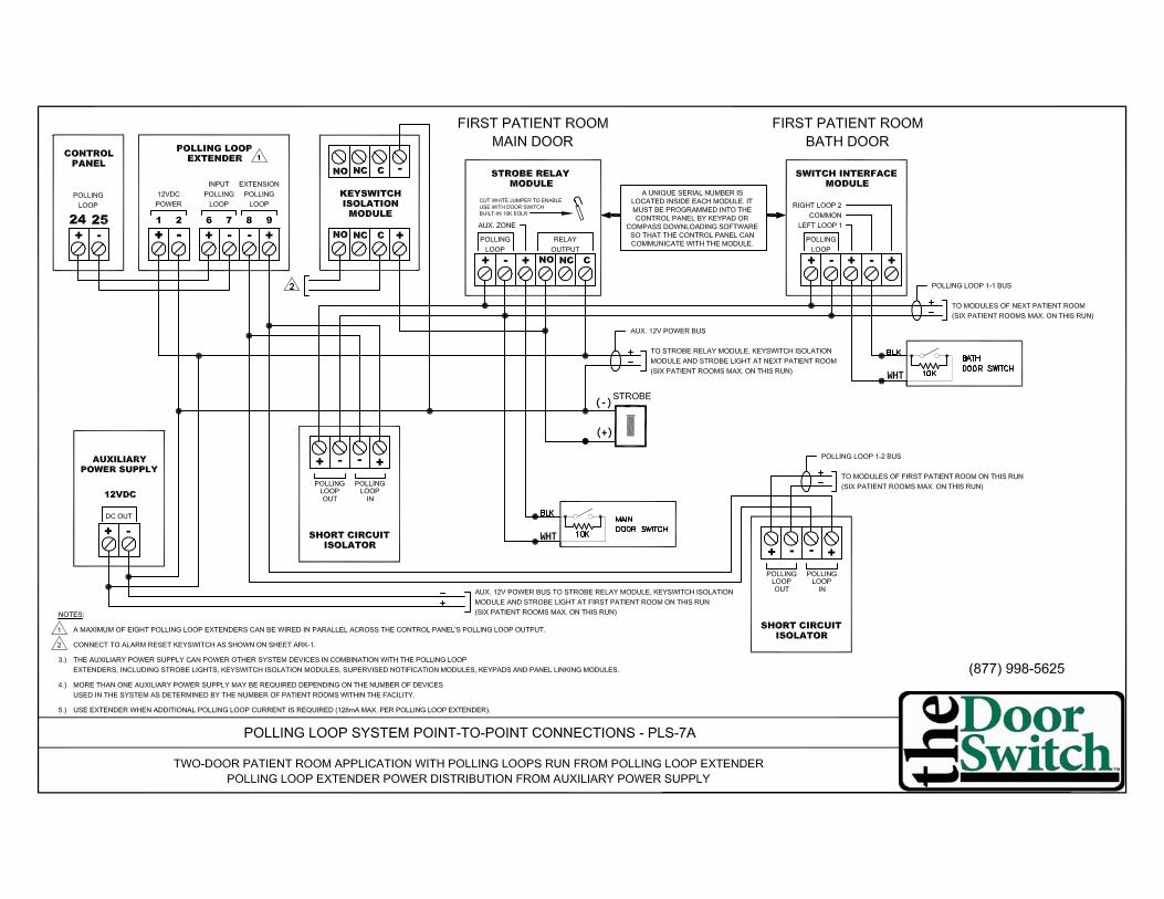
Polling loop rating: 128mA max. See Installation
and Setup Guide for maximum number of devices
supported and maximum wire run length
Zone resistance (Excluding EOLR):
ZONE 1,8: 100 OHMS MAXIMUM
ALL OTHER ZONES: 300 OHMS MAXIMUM
ZONE 1
ZONE 2 ZONE 3 ZONE 4 ZONE 5 ZONE 6 ZONE 7 ZONE 8 ZONE 9
2-W
IRE
SM
OK
E
DE
TE
CT
OR
LO
OP
(A
lso
su
pp
ort
s N
O/N
C B
urg
co
nta
cts
)
PO
LL
ING
LO
OP
Da
ta in
Da
ta o
ut
1 2 3 4 5 6 7 8 9 10 11 12 13 14 15 16 17 18 19 20 21 22 23 24 25 26 27 28 29 30
NOTE: THE AC TRANSFORMER SHOULD NOT BE PLUGGED INTO A SWITCHED OUTLET. WHEN POWERING UP THE PANEL, PLUG THE TRANSFORMER IN BEFORE CONNECTING THE BATTERY.
See Installation Instructions for max # of keypads
and for max wire run length.
ALARM SOUNDER OUTPUT 10VDC - 13.8VDC
AUXILIARY POWER OUTPUT 9.6VDC - 13.8VDC, 750mA maximum Note: Include current drawn by keypads and polling loop devices when making auxiliary power calculations.
+ -
1 2 3 4 5 6 7 8 9
1. Not Used 2. Ground- 3. Out 1 4. Ground- 5. Out 2 6. Ground- 7. Out 3 8. Ground 9. Out 4
Optional programming: Out 1: Smoke Detector Reset Out 2: Armed LED Out 4: Ready LEDRatings for Out 1: Active: 10VDC-13.8VDC through 4k OHMS Not Active: 100 OHMS to ground Ratings for out 2-4: Active: 10VDC-13.8VDC through 5k OHMS Not Active: 1k OHMS to ground
N.C.
N.O.
N.O. N.O.
2k EOLR (note 1,2)
N.O. N.O.
N.O.
N.C.
N.O.
2k EOLR (note 1)
2k EOLR (note 1,3)
N.C.
+ -
J7
1 2 3 4 5 6 7 8 9
J8
MAKE CONNECTIONS USING No. 4142TR CABLE
Fire Usage
Burg. Usage
CONNECTION OF THE FIRE ALARM SIGNAL TO
A FIRE ALARM HEADQUARTERS OR A CENTRAL
STATION SHALL BE PERMITTED ONLY WITH THE
APPROVAL OF THE LOCAL AUTHORITY HAVING
JURISDICTION. THE BURGLAR ALARM SIGNAL
SHALL NOT BE CONNECTED TO A POLICE
EMERGENCY NUMBER.
1. In 2 2. Ground 3. In 3 (1361X10 sync) 4. Not Used 5. Ground 6. Out 5 (1361X10 data) 7. Out 6 8. Ground 9. Ground
Red Jumper (note 1)
DOC LOAD NO.: 5
J7 Header J8 Header
5193SD SMOKE
WARNING: TO PREVENT RISK OF ELECTRICAL SHOCK, DISCONNECT TELCO JACK BEFORE
SERVICING THIS PANEL.
THIS EQUIPMENT SHOULD BE INSTALLED IN ACCORDANCE WITH THE NATIONAL FIRE PROTECTION ASSOCIATION'S STANDARD 72 (NATIONAL FIRE PROTECTION ASSOC., BATTERY MARCH PARK. QUINCY, MA. 02169). PRINTED INFORMATION DESCRIBING PROPER INSTALLATION, OPERATION, TESTING, MAINTENANCE, EVACUATION PLANNING AND REPAIR SERVICE IS TO BE PROVIDED WITH THIS EQUIPMENT.
WEEKLY TESTING IS REQUIRED TO ENSURE PROPER OPERATION OF THIS SYSTEM.
Zone response time:
ZONES 1: 350mSec-500mSec
COMPLIES WITH FCC RULES, PART 68 FCC REGISTRATION NO. AC398U-68192-AL-E RINGER EQUIVALENCE: 0.7B
THIS DEVICE COMPLIES WITH PART 15 OF FCC RULES. OPERATION IS SUBJECT TO THE FOLLOWING TWO CONDITIONS: (1) THIS DEVICE MAY NOT CAUSE HARMFUL INTERFERENCE, AND (2) THIS DEVICE MUST ACCEPT ANY INTERFERENCE RECEIVED, INCLUDING INTERFERENCE THAT MAY CAUSE UNDESIRED OPERATION.
Notes For UL Household
Fire Installations:
1. Use 12VDC, 14AH battery
2. Maximum auxiliary current,
including polling loop 300mA
3. Combined alarm and auxiliary
power output and polling loop
current must be limited to
750mA for UL985 Household
Fire Installations.
Blue Jumper (note 5)
VISTA-128BPT SUMMARY OF CONNECTIONS
4208U
(Refer to Installation and Setup Guide for information concerning
Direct Wire Downloading and printer connections.)
RE
D (
+)
BL
K (
-)B
LK
(-)
BATTERY TABS
ALL CIRCUITS ARE POWER LIMITED EXCEPT THE OUPUT OF THE BACKUP BATTERIES.SEE INSTALLATION INSTRUCTIONS 800-06903 REV. A. DATED 6/10
FOR DRY, INDOOR USE ONLY
ZONE INPUT SPECIFICATIONS
ZONE 8ZONES 2-7 EOLR CONFIG.
Maximum Loop Current (shorted loop): 7.4mA Maximum Loop Voltage (open loop): 13.3VDC Loop Short: 0V - 1.5V - 300 ohms total resistance) Loop Normal: 4.2 - 6.8V, 1.2k - 2.6k Loop Open: 7.2V - 13.3V, 3k -
Maximum Loop I: 9mA Maximum Loop V: 13.3VDC Loop Short: 0 - 2.2V - (0 - 300 ohms) Loop Normal: 5 - 9V (0.9k - 3.4k) Loop Open: 10V - 13.3V, 3.8k -
ZONE 9
Maximum Loop I: 4mA Maximum Loop V: 13.3V Loop Short: NA Loop Normal: 0 - 1.5V (0 ohms - 400 ohms) Loop Open: 5.3V, 2.2k -
MAKE CONNECTIONS FROM J9 USING NO. VT-SERCBL CABLE TO 9-PIN FEMALE NULL MODEM.
J9
TXD
RXD
RTS/DTR
CTS/DSR
GND
TB4
Connect to 12VDC, 4AH
or 12VDC, 7AH
GEL CELL BATTERY
CHARGING VOLTAGE 13.65VDC
See
Installation and Set up Guide for required capacity
NOTE
In UL Installations battery capacity for emergency stand by is at least 24 hours
Replace
every 3 years
** RESIDENTIAL FIRE AND RESIDENTIAL BURGLARY CONTROL UNIT WITH DACT
* With Model COM-UL Commercial Enclosure.
** With Model RES-UL Residential Enclosure.NOTES:
1. Zone 1 may be selected for EOLR supervised or normally closed (no EOLR) operation via cut jumper. (Cut red jumper for normally closed operation. Do not cut for Fire Usage). Zones 2-8 may be selected for either operation via program field *41. Zone 1 supports 2-wire smoke detectors.
See Installation and Setup Guide for recommended type and maximum number of detectors supported. Zone 7 may be used for remote keyswitch arming/disarming. See Installation and Setup Guide for wiring instructions.
2. 3.
Cut blue jumper to disable supervision of alarm sounder output. Leave jumper intact to supervise output. (See Installation and Setup Guide for Programming and Wiring Instructions). Canadian installation must comply with CAN/ULC-S302, CAN/ULC-S301 and CSA C22.1. The use of Recognized limited-energy cable for connections to the initiating devices, indicating devices, and supplementary devices for those units having their energy limited to a maximum of 100 volt-amperes is required.
4.
5. 6.
* RESIDENTIAL FIRE AND COMMERCIAL AND RESIDENTIAL BURGLARY, LOCAL AND POLICE STATION, MERCANTILE SAFE AND VAULT, CENTRAL STATION CONTROL UNIT WITH DACT
J9 CONNECTOR NOT EVALUATED
BY UL
USE LIMITED-ENERGY CABLE FOR ALL CONNECTIONS


WHT
WHT
(-)
(+)

(-)
(+)
WHT

(-)
(+)
WHT
WHT

(-)
(+)
WHT

(-)
(+)
WHT
WHT

(-)
(+)
WHT
(-)
(+)
WHT
WHT

(-)
(+)
WHT