types 1010, 1017 and 1220 hydraulic pressure gauges with
TRANSCRIPT

• 41⁄2˝ full-size Bourdon tube• Patented Duratube™ with as welded tube
construction controls stress for longer life• “ Round Cap Tip” construction lowers
stresses for longer life• Micrometer adjustable pointer.• Exclusive Teflon coated 400 series stain-
less steel rotary movement for longer life• PLUS!™ Performance Option:
- Liquid-filled performance in a dry gauge- Fights vibration and pulsations without
liquid-filled headaches - Order as option XLL
• Epoxy-coated system for superior corrosion resistanceType 1010, 1017 and 1220 Ashcroft®
pressure gauges are designed for use onhydraulic presses, pumps and systemsusing hydraulic fluid, Ashcroft generalservice gauge Types 1010, 1017 and 1220with the XTR variation meet the needs ofmany hydraulic applications. Equippedwith a slotted link and throttle screw, thesegauges are available with either a psirange or a psi range with a correspondingtons-on-ram scale. Use the nomograph onthe reverse page to help determine theappropriate tons-on-ram scale.
PRODUCT SPECIFICATIONSModel Number: 1010, 1017 and 1220Accuracy: 1⁄2% full scale (Grade 2A,
ASME B40.100)Ranges: Vacuum – 100,000 psi*Dial Size: 41⁄2˝, 6˝, 81⁄2˝ diameter Case Material: Black, aluminum, solid frontWeather Protection: Dry Case: IP54 Liquid filled or
hermetically sealed case: IP65Ring:
41⁄2˝ & 6˝ Dial: Threaded reinforced black polypropylene
81⁄2˝ Dial: Hinged, aluminum, blackepoxy coated
Window: GlassDial: Aluminum, white background,
black pressure scaleBourdon Tube C510 Phos. bronze/brass (A)(1)
and Socket: 316L SS/Steel (R)(2)
316L SS/316L SS (S)(2)
K Monel/ Monel (P)(2)
Inconel 718 (WW)(2)(3)
Pointer: Micrometer adjustableMovement: Rotary, 400 SS, Teflon® coated
pinion gear and segmentConn. Size: 1⁄4˝, 1⁄2˝ NPT, 1⁄4˝ high pressure
for gauges 20,000 psi andabove
Conn. Location: Lower or back
PRODUCT OPTIONSFill: L-Glycerin-Standard
XGV-Silicone -OptionalXGX-Halocarbon-Optional
PLUS!™
Performance: XLLHermeticallySealed, IP65: HFlush MountingRing: X56Receiver Gauge: XPRShatter ProofGlass Window: XSGAcrylic Window: XPDRed Set Hand: XSHMax. Pointer: XEP(1) Joints silver brazed, (2) Joints welded, (3) See Bulletin DU-5 1379 HP
Types 1010, 1017 and 1220 Hydraulic PressureGauges With PLUS!™ Performance Option
Ashcroft Inc., 250 East Main Street, Stratford, CT 06614 USATel: 203-378-8281 • Fax: 203-385-0408email: [email protected] • www.ashcroft.com
All specifications are subject to change without notice. All sales subject to standard terms and conditions. © Ashcroft Inc. 2015 03/15
Pressure – psi
Range Figure Minor interval Graduation
0/60 5 10/100 10 10/160 20 20/250 50 50/400 50 50/600 50 50/800 100 100/1000 100 100/1600 200 20
STANDARD RANGE TABLE**
BULLETIN HG-1 1010-1017-1220
TEMPERATURE LIMITSAmbient Process Storage
Dry –20/200°F(1) –20/250°F(1) –40/250°F(–29/93°C) (–29/121°C) (–40/121°C)
LF 20/150°F 20/200°F 0/150°F(glycerin) (7/66°C) (7/93°C) (–18/66°C)
–40/150°F –40/200°F –40/150°F(silicone) (–40/66°C) (–40/93°C) (–40/66°C)–40/150°F –40/200°F –40/150°F(halocarbon) (–40/66°C) (–40/93°C) (–40/66°C)
Note: Other than discoloration of the dial and hardening of thegasketing that may occur as ambient or process temperaturesexceeds 150°F, non-liquid-filled gauges with standard glass win-dows, can withstand continuous operating temperatures up to250°F (121°C). Liquid-filled gauges can withstand 200°F (93°C)but glycerin fill and acrylic window will tend to yellow. Accuracyat temperatures above or below the reference ambient tempera-ture of 68°F (20°C) will be affected by approximately .4% per25°F. Gauges with welded joints will withstand 750°F (450°F(232°C) with silver brazed joints) for short times without rupture,although other parts of the gauge will be destroyed and calibra-tion will be lost. For continuous use and for process or ambienttemperatures above 250°F (121°C), a diaphragm seal or capillaryor siphon is recommended.
(1) Available for temperatures below –20°F, see ProductInformation page ASH/PI-21B for details.
Ash Bul HG-1 1010-1017-1220_layout 3/4/15 9:18 PM Page 1
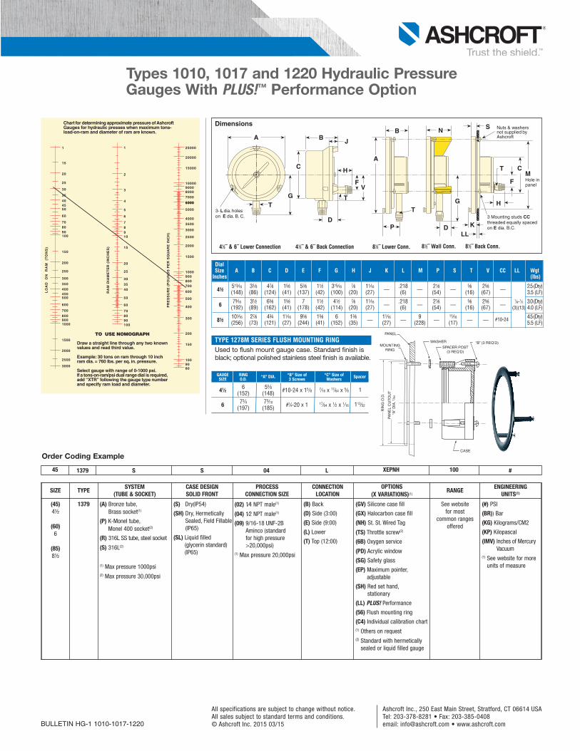
GAUGE RING “B” Size of “C” Size ofSIZE O.D. “A” DIA. 3 Screws Washers Spacer
41⁄2 6 55⁄8 #10-24 x 15/8 7⁄16 x 17⁄64 x 5⁄8 1(152) (148)
6 73⁄4 73⁄10 17⁄64 x 1⁄2 x 1⁄16 113⁄32(197) (185) #1⁄4-20 x 1
Types 1010, 1017 and 1220 Hydraulic PressureGauges With PLUS!™ Performance Option
Ashcroft Inc., 250 East Main Street, Stratford, CT 06614 USATel: 203-378-8281 • Fax: 203-385-0408email: [email protected] • www.ashcroft.com
All specifications are subject to change without notice. All sales subject to standard terms and conditions. © Ashcroft Inc. 2015 03/15
DialSize A B C D E F G H J K L M P S T V CC LL Wgt
Inches (lbs)
41⁄2513⁄16 33⁄8 47⁄8 15⁄8 53⁄8 11⁄2 315⁄16 7⁄8 11⁄16
—.218
—21⁄8
—5⁄8 25⁄8
—2.5 (Dry)
(148) (86) (124) (41) (137) (42) (100) (20) (27) (6) (54) (16) (67) 3.5 (LF)
679⁄16 31⁄2 65⁄8 15⁄8 7 11⁄2 41⁄2 7⁄8 11⁄16
—.218
—21⁄8
—5⁄8 25⁄8
—1⁄8-1⁄2i 3.0 (Dry)
(192) (89) (162) (41) (178) (42) (114) (20) (27) (6) (54) (16) (67) (3)(13)i4.0 (LF)
81⁄2101⁄16 27⁄8 43⁄4 11⁄16 95⁄8 15⁄8 6 13⁄8
—11⁄16
—9
—11⁄16
— — #10-24ii ii 4.5 (Dry)
(256) (73) (121) (27) (244) (41) (152) (35) (27) (228) (17) 5.5 (LF)
BULLETIN HG-1 1010-1017-1220
Dimensions
41⁄2˝ & 6˝ Lower Connection 41⁄2˝ & 6˝ Back Connection 81⁄2˝ Back Conn.81⁄2˝ Wall Conn.81⁄2˝ Lower Conn.
H
T
A
GT
C
V
B J
D
F
3- L dia. holes on E dia. B. C.
D
A
T
B
G
N
MHole inpanel
Nuts & washersnot supplied byAshcroft
C
S
T
F
H
LLK
3 Mounting studs CC threaded equally spaced on E dia. B.C. P
45 1379 S S 04 L XEPNH 100 #
Order Coding Example
SIZE TYPESYSTEM
(TUBE & SOCKET)CASE DESIGNSOLID FRONT
PROCESSCONNECTION SIZE
CONNECTIONLOCATION
OPTIONS (X VARIATIONS)(1)
RANGEENGINEERING
UNITS(1)
(45)4½
(60)6
(85)8½
1379 (A) Bronze tube, Brass socket(1)
(P) K-Monel tube, Monel 400 socket(2)
(R) 316L SS tube, steel socket
(S) 316L(2)
(1) Max pressure 1000psi(2) Max pressure 30,000psi
(S) Dry(IP54)
(SH) Dry, HermeticallySealed, Field Fillable(IP65)
(SL) Liquid filled (glycerin standard)(IP65)
(02) 1⁄4 NPT male(1)
(04) 1⁄2 NPT male(1)
(09) 9/16-18 UNF-2BAminco (standard for high pressure>20,000psi)
(1) Max pressure 20,000psi
(B) Back
(D) Side (3:00)
(E) Side (9:00)
(L) Lower
(T) Top (12:00)
(GV) Silicone case fill
(GX) Halocarbon case fill
(NH) St. St. Wired Tag
(TS) Throttle screw(2)
(6B) Oxygen service
(PD) Acrylic window
(SG) Safety glass
(EP) Maximum pointer,adjustable
(SH) Red set hand, stationary
(LL) PLUS! Performance
(56) Flush mounting ring
(C4) Individual calibration chart(1) Others on request(2) Standard with hermetically
sealed or liquid filled gauge
See website for most
common rangesoffered
(#) PSI
(BR)) Bar
(KG) Kilograms/CM2
(KP) Kilopascal
(IMV) Inches of MercuryVacuum
(1) See website for moreunits of measure
TYPE 1278M SERIES FLUSH MOUNTING RINGUsed to flush mount gauge case. Standard finish isblack; optional polished stainless steel finish is available.
PAN
EL
CU
TOU
T“A
” DIA
. 1/6
4
RIN
G O
.D.
WASHER
SPACER POST(3 REQ’D)
“B” (3 REQ’D)
PANEL
CASE
MOUNTINGRING
RA
MD
IAM
ET
ER
(IN
CH
ES
)
1
2
3
4
5
6
78
Chart for determining approximate pressure ofAshcroftGauges for hydraulic presses when maximum tons-load-on-ram and diameter of ram are known.
910
15
20
25
30
35
40
50
60
708090100
1
15
20
25
30
35
404550
60
708090100
150
200
250
300
350
400450500
600
700
8009001000
1500
2000
2500
3000
LO
AD
ON
RA
M(T
ON
S)
TO USE NOMOGRAPH
Draw a straight line through any two knownvalues and read third value.
Example: 30 tons on ram through 10 inchram dia. = 760 lbs. per sq. in. pressure.
Select gauge with range of 0-1000 psi.If a tons-on-ram/psi dual range dial is required,add “XTR” following the gauge type numberand specify ram load and diameter.
25000
20000
15000
1000090008000
7000
60006000
5000
4000
3500
3000
2500
2000
1500
1000900800700
600
500
400
300
200
150
1009080
PR
ES
SU
RE
(P
OU
ND
S P
ER
SQ
UA
RE
IN
CH
)
Ash Bul HG-1 1010-1017-1220_layout 3/4/15 9:18 PM Page 2