type tec, transformer electronic control system · type tec, transformer electronic control system...
TRANSCRIPT

Type TEC, Transformer Electronic Control System Product manual TEC Monitor
1ZSC 954003-012 en, Rev. 3, 2004-11-05

2
This document must not be copied without our written permission, and the contents thereof must not be imparted to a third party nor be used for any
unauthorized purpose. Contravention will be prosecuted.
3
Contents
1 Technical manual.....................................................................................5 1.1 TEC concept ..............................................................................................5 1.2 Functions in TEC.......................................................................................5 1.2.1 Transformer top and bottom oil temperature.............................................5 1.2.2 Transformer core yoke temperature...........................................................5 1.2.3 Current measurement .................................................................................6 1.2.4 Voltage measurement.................................................................................6 1.2.5 Transformer load........................................................................................6 1.2.6 Hot-spot calculation...................................................................................6 1.2.7 Service prediction cooling equipment .......................................................6 1.2.8 Ageing........................................................................................................6 1.2.9 Transformer temperature balance ..............................................................6 1.2.10 Tap-changer temperature balance..............................................................6 1.2.11 Hydrogen equivalent detection ..................................................................7 1.2.12 Moisture in transformer oil detection ........................................................7 1.2.13 Tap-changer contact wear ..........................................................................7 1.2.14 Tap-changer position .................................................................................7 1.2.15 Cabinet conditions .....................................................................................7 1.2.16 Loading forecasts.......................................................................................7 1.2.16.1 Hot-spot forecast........................................................................................7 1.2.16.2 Overload capacity ......................................................................................7 1.2.17 Event log ....................................................................................................7 1.2.18 Documentation...........................................................................................8 1.2.19 Tap-changer service videos........................................................................8 1.3 TEC Monitor web software .......................................................................8
2 Installation manual ................................................................................11 2.1 Fiber optic ................................................................................................11 2.2 PC.............................................................................................................11 2.3 Installation of software in the TEC Monitor ...........................................12 2.4 Software requirements for remote PC .....................................................13
3 Operation manual ..................................................................................13 3.1 Open TEC Monitor web ..........................................................................13 3.2 Station interface main screen...................................................................14 3.2.1 Transformer information overview..........................................................14 3.2.1.1 Tool tip.....................................................................................................14 3.2.2 Navigation and quick buttons ..................................................................14 3.2.3 View.........................................................................................................15 3.2.4 Transformer overview..............................................................................15 3.2.5 Cooling.....................................................................................................15 3.2.6 Transformer temperatures........................................................................18 3.2.7 Transformer load......................................................................................19 3.2.8 Tap-changer contact wear ........................................................................20 3.2.9 Tap-changer temperature .........................................................................23 3.2.10 Hydrogen Gas ..........................................................................................25 3.2.10.1 Hydrogen guidelines ................................................................................26

4
3.2.11 Moisture in oil..........................................................................................27 3.2.12 TEC cabinet condition .............................................................................27 3.2.12.1 Accumulated conditions...........................................................................28 3.2.13 Sensor failure ...........................................................................................29 3.2.13.1 Current sensor ..........................................................................................30 3.2.13.2 Other 4-20 mA sensors ............................................................................30 3.2.13.3 Pt100 ........................................................................................................30 3.2.14 Event log ..................................................................................................30 3.2.14.1 To acknowledge and reset Alarm/Warning/Trip .....................................31 3.2.15 Forecasts ..................................................................................................33 3.2.15.1 Hot-spot calculation .................................................................................35 3.2.16 24 h Hot-spot forecast ..............................................................................36 3.2.17 Documentation .........................................................................................38 3.2.18 Video........................................................................................................40
4 Maintenance and service manual .........................................................41 4.1 TEC Maintenance Program......................................................................41 4.1.1 Settings.....................................................................................................41 4.1.2 Database...................................................................................................41 4.1.3 Sensor.......................................................................................................42 4.1.4 Tap-changer .............................................................................................42 4.1.5 Set document path....................................................................................43 4.1.6 Video settings...........................................................................................44 4.1.7 Select language ........................................................................................44 4.1.8 Delete all alarms and warnings ................................................................45 4.1.9 Delete all collected data from TEC database...........................................45 4.1.10 Backup the database to CD-RW ..............................................................45 4.1.11 Restore the TEC database ........................................................................45 4.1.12 Scaling 4-20 mA sensors..........................................................................46 4.1.13 Set contact service date............................................................................46 4.1.14 Set contact exchange date ........................................................................47 4.1.15 Start and Stop services .............................................................................47 4.1.16 Position name...........................................................................................48 4.2 Guide for troubleshooting the TEC-system .............................................49 4.2.1 Station PC ................................................................................................49 4.2.2 TEC cabinet .............................................................................................50
5 Contact list ..............................................................................................51

5
1 Technical manual
1.1 TEC concept The general TEC concept is shown in Fig. 1. The TEC cabinet and the TEC related software to the PC are included as standard. The PC station interface is called TEC Monitor. It is possible to use a TEC without connection to a station PC, but much of the functionality will then be lost.
Fig 1. The TEC concept.
Fiber optic cable
• The connections between the TECs and the TEC server are made via optic cables.
TEC Monitor server
• Processor > 1.8 GHz, 512 Mbyte RAM and 40 GB
• Operating system: Windows XP
• Fiber optic to serial converter
• For remote access of the PC, a modem or broadband connection is needed.
1.2 Functions in TEC The following functionality is available in TEC version 1.02:
1.2.1 Transformer top and bottom oil temperature The transformer top and bottom oil temperature will be measured. The values will be shown in TEC Monitor. Historical values can also be displayed in TEC Monitor.
1.2.2 Transformer core yoke temperature The core yoke temperature can be measured. The values will be shown in TEC Monitor. Historical values can also be displayed in TEC Monitor.
TEC CABINET
Fibre Optic Bus
ON CABINET
ALARM
WARNING
NORMAL
DisplayON CABINET
ALARM
WARNING
NORMAL
Display
TEC PC in station
Sensors
Motor boardMotor board
AC to
24V DC
TRANSFORMER CABINET

6
1.2.3 Current measurement The current from transformer CTs are used to calculate the current in the windings and bushings. The accuracy of the current measurement is approx. 3 % of full load.
1.2.4 Voltage measurement The voltage on the high voltage side can be displayed. The values will be shown in TEC Monitor. Historical values can also be displayed in TEC Monitor.
1.2.5 Transformer load The load in the transformer will be calculated from the current in the windings. The winding with highest ratio between measured value and rated value is used for showing the load in the transformer.
1.2.6 Hot-spot calculation The winding hot-spot will be calculated to fulfill IEC. The values will be shown in TEC Monitor. Historical values can also be displayed in TEC Monitor.
1.2.7 Service prediction cooling equipment The time each cooling group has been in operation is calculated and displayed in the station interface. It can be used to predict when service is needed. A log is also available to see when action has been taken on the cooling equipment.
1.2.8 Ageing The ageing due to heat at the winding hot-spot can be calculated for both normal craft paper (according to IEC) and thermally upgraded paper (according to IEEE). The accumulated and actual ageing will be shown in TEC Monitor.
1.2.9 Transformer temperature balance The transformer temperature balance function will keep track on the temperature in the transformer and compare with the theoretically calculated temperature. The default setting is that, if the average transformer temperature becomes more than 15 ºC higher than expected for 24 h, there will be an alarm. The function can indicate a cooling problem at lower load conditions before the problem gives a warning due to high top oil temperature. The calculated temperatures shall be used as references to the actual temperatures over a longer time.
1.2.10 Tap-changer temperature balance This function calculates if there is excessive heat generation in the tap-changer. At normal conditions there is a known balance between the theoretical calculated losses in the tap-changer and the heat transferred from the tap-changer to its surroundings. The default setting is that, if the average temperature in the tap-changer is more then 15 ºC above the calculated value for 24 h there will be an alarm.

7
1.2.11 Hydrogen equivalent detection This function will receive a signal from a hydrogen detector, which is a gas-in-oil detector that is sensitive to H2, CO, C2H2 and C2H4. The resulting value is an H2 equivalent ranging from 0 – 2000 ppm.
1.2.12 Moisture in transformer oil detection This function will receive a signal from a moisture sensor and recalculate it to the ppm value of moisture in the oil. The requested levels for warning and alarm regarding maximum moisture content in the oil can be entered in to order data sheet. This value is then used to generate a configuration file that is included with the shipped system.
1.2.13 Tap-changer contact wear The contact wear function will keep track of the wear on each contact at operations, and calculate how much material has been worn off. From that information it will calculate operations and time to next service/contact exchange. As those events are approaching there will be warnings, and if actions are not taken in due time there will be alarms. This function shall be used to predict and remind when overhaul and contact exchange are needed.
1.2.14 Tap-changer position This function keeps track of the tap-changer position.
1.2.15 Cabinet conditions This function reads the temperature and the relative humidity on the processor board in the cabinet. The readings will be available both for the present time and also as a histogram showing the frequency of different temperature and humidity. The values will be stored in TEC Monitor. Historical values can also be displayed in a histogram in TEC Monitor.
1.2.16 Loading forecasts There are two different possibilities to forecast the loading in TEC Monitor. Actual values from the TEC and pre-loaded transformer data are used for these calculations.
1.2.16.1 Hot-spot forecast
By only filling in 2 loading ratios over the next 10 hours, the predicted hot-spot can be calculated over that period.
1.2.16.2 Overload capacity
A prediction of the maximum allowed load under the existing ambient conditions is displayed in the main interface. At this loading the top oil and hot-spot temperature should not exceed preset values in the order data sheet. (See also the Appendix.)
1.2.17 Event log In the event log all alarms and warnings are collected. After notification and when action has been taken, the alarm and warning signals can be switched off.

8
1.2.18 Documentation All documentation for the transformer and its components, including TEC, can be placed here.
1.2.19 Tap-changer service videos Films about maintenance of tap-changers are available here.
1.3 TEC Monitor web software The software is loaded to the PC at delivery. It consists of three major parts:
• An OPC server that administrates data.
• A database that stores service data. As long as the server is switched on, the database will store 2 years of measured data. After that, all data will be deleted and a new 2- year period starts. Data for 20 years will be stored in the year table in the database, which means that the average value for one day will be the stored data over long term. Data on accumulated ageing and time to next tap-changer service will remain correct, but to save the basic service history it is necessary to take regular back-ups of the database (see Software maintenance / Back-up of database).
• The user interface as described in PC interface.
1. Top oil temperature
The transformer tank top oil temperature is displayed here. If the sensor fails, the top-oil is calculated based on the bottom oil temperature.
2. Hot-spot temperature The calculated hottest spot temperatures in the transformer windings are displayed here. The hot-spot temperatures are displayed in order from top: High-voltage winding, Low-voltage winding. The hot-spot temperature is calculated according to IEC 60354 (1991-09) at OF cooling; the top oil can be warmer than

9
the hot-spot at low loads. The hot-spot temperature is calculated without delay (winding time constant=0), thus coolers will start earlier at a rapid load increase.
3. Bottom oil temperature The transformer tank bottom oil temperature is displayed here. If the sensor fails, the bottom oil is calculated based on the top-oil temperature.
4. Current on High Voltage The current in the high voltage bushing is displayed here. If a sensor fails, the calculated hot-spot of that winding will be too low. The accuracy of the current measurement is approx. 3 % of full load.
5. Current Low Voltage The current in the low voltage bushing is displayed here. If a sensor fails, the calculated hot-spot of that winding will be too low. The accuracy of the current measurement is approx. 3 % of full load.
6. Ambient air temperature The ambient air temperature at the transformer is displayed here. Two sensors are used, one located in the sun and one in shadow. Calculations are primarily based upon the temperature in the shadow. If the shadowed sensor fails, the value from the sun sensor will be displayed and used in calculations. If the sun sensor fails, an abnormal value will be displayed but that does not influence any calculations.
7. Time to service The estimated time to service due to contact wear and the device that needs the service action are displayed here. The estimation assumes that the tap-changer will be operated equally often and at the same load in the future as in the service history.
8. Ageing The thermal ageing at the hot-spot of the winding is displayed here. The calculation is based on the hot-spot temperature in the hottest winding. The ageing is calculated according to:
• IEC 60076-7 for non-thermally upgraded paper.
• The expected service life shall only be used for reference purposes:
• IEC 150 000 h = 17.1 year
“Ageing in years” is the calculated ageing in the winding since TEC started the measurements. At "Relative Now", the ageing rate is displayed in % of the ageing rate at 98 ºC (IEC).
• The Relative (ageing) Now is named:
“Relative ageing rate” by IEC
• If the hot-spot temperature of the hottest winding cannot be calculated, e.g. because of a current transformer failure, the second hottest winding will be used for the ageing calculation.
9. Tap-changer position and temperature The tap-changer position and tap-changer oil temperature are displayed here. If a sensor fails, no value will be displayed. If the transformer is equipped with more than one tap-changer, the temperature of the hottest tap-changer is displayed. UC and UB tap-changers are normally located at the transformer cover. At normal service conditions the temperature of the tap-changer should not be more than 10-15 °C above the transformer top oil temperature. For tap-changers in industrial applications, the temperature can be up to 25 °C above the top oil temperature. Sometimes the UC tap-changer is assembled in a separate compartment on the transformer tank wall. In these cases the temperature of the tap-changer can be

10
lower, especially if there is no oil connection between the transformer and the compartment. UZ tap-changers are assembled on the transformer tank wall. At normal service conditions the temperature of the tap-changer should be below the transformer top oil temperature. Under some transformer start-up procedures the UZ tap-changer can be warmer than the transformer for some hours. The temperature of a tap-changer in an industrial application can be above the top oil temperature.
10. Hydrogen gas detector The hydrogen equivalent in the transformer tank is displayed here. This symbol is displayed when a hydrogen gas detector is installed. The value is displayed in ppm (parts per million). Both the absolute value and the increase rate (see View / Hydrogen Gas) give important information. If the sensor fails, no value will be displayed.
11. Cooling The status of the cooler groups is displayed here. A blue fan symbol represents an active cooler group; an orange fan symbol represents a non-activated cooler group.
12. Overload capacity
Predictions of the highest allowed load without the top oil and hot-spot temperature exceeding preset values in the order data sheet.
13. Moisture in oil detection
The moisture in the transformer oil is displayed here.
14. Last update The time when this site was last updated is displayed here.
15. Load The highest load is displayed here.
16. Core yoke The temperature on the core yoke is displayed here.
17. Celcius or Fahrenheit Changes the temperature scale displayed in TEC Monitor.
18. Log out Log out current user.
11
2 Installation manual
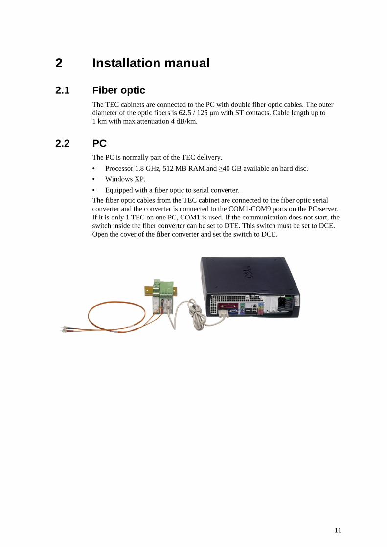
2.1 Fiber optic The TEC cabinets are connected to the PC with double fiber optic cables. The outer diameter of the optic fibers is 62.5 / 125 µm with ST contacts. Cable length up to 1 km with max attenuation 4 dB/km.
2.2 PC The PC is normally part of the TEC delivery.
• Processor 1.8 GHz, 512 MB RAM and ≥40 GB available on hard disc.
• Windows XP.
• Equipped with a fiber optic to serial converter.
The fiber optic cables from the TEC cabinet are connected to the fiber optic serial converter and the converter is connected to the COM1-COM9 ports on the PC/server. If it is only 1 TEC on one PC, COM1 is used. If the communication does not start, the switch inside the fiber converter can be set to DTE. This switch must be set to DCE. Open the cover of the fiber converter and set the switch to DCE.

12
2.3 Installation of software in the TEC Monitor The software structure in the TEC is shown below. This manual describes the software in the TEC Monitor. The OPC server, the TEC service, the database and the OPC client work independently from the TEC Monitor.
Fig. 2: The software layout
All software on the TEC Monitor in the station is loaded at the delivery. The software consists of:
• OPC server that communicates with the TECs and holding data
• TEC client that updates the database
• OPC client that updates the user interface with the latest data from the transformer
• Database where the measured data for every 5 minutes are stored. The database will store 2 years of measured data. After 2 years the oldest data will be overwritten by new data. We recommend taking regular back-ups of the database.
• TEC Monitor interface which is the web application that is described in this manual
• Anti-virus program that protects the PC from viruses.
• Firewall program to stop unauthorized contacts with the computer.
A back-up media, containing the complete installation is delivered together with the TEC Monitor for recovery purpose.

13
2.4 Software requirements for remote PC To view the TEC Monitor web site with full functionality, the following softwares is required:
• Microsoft Internet Explorer 6.0 or higher
• Java plug-in 1.3.1 or higher
• Adobe Acrobat Reader 5.0 or higher
• Windows media player 7.0 or higher
3 Operation manual
3.1 Open TEC Monitor web • Start Internet Explorer.
• Type http://localhost in the address field and press enter. This is only on the PC in station. If the PC is connected to a local network, it will be a IP-address to type in the address field.
• If log in is required, enter user name and password for “TEC Monitor user” or “TEC Maintenance user”.

14
3.2 Station interface main screen
3.2.1 Transformer information overview The start screen shows the actual status of the transformer. The displayed values in the frames are:
1. The transformer tank top oil temperature
2. The calculated hot-spot temperatures in the transformer windings
3. The transformer tank bottom oil temperature
4. The current (and voltage) in the high voltage bushing
5. The current in the low voltage bushing
6. Ambient air temperature in the sun and in the shadow
7. The estimated time to service due to contact wear
8. The thermal ageing at the hot-spot of the winding
9. “Ageing in years” is the calculated ageing in the winding since TEC was started
10. “Relative Now”, the ageing rate is displayed in % of the ageing rate at 98 ºC (IEC normal paper) or 110 ºC (IEEE thermally upgraded paper)
11. The tap-changer position and tap-changer oil temperature
12. The hydrogen equivalent in the transformer tank (parts per million)
13. The status of the cooler groups is displayed here by symbols. A blue fan symbol represents an active cooler group; an orange fan symbol represents a non-activated cooler group.
Right clicking on any relevant object of the transformer (bushing, tap-changer, cooler group) will display the relevant information for the device in a pop-up window. For more detailed information, please refer to the chapter describing each screen.
History diagrams are available by clicking on the corresponding symbols in the status-bar displayed in the main window of the TEC PC application.
Context sensitive help information is provided when moving the cursor over any of the displayed symbols.
3.2.1.1 Tool tip
Moving the cursor over the displayed values will show context sensitive help information.
3.2.2 Navigation and quick buttons Lower levels with panels showing more detailed information are reached with the quick buttons or with the drop-down menus. The quick button at the top represents the top level. This button is displayed at the lower levels and is used to return to the top level. The quick buttons have the same functions as the indicated drop-down menus.

15
Information on the panels under the Cooling button is therefore given in View / Cooling etc.
The status light of the top-level button is always the same as the most serious of the other lights. Any sensor failure, true overheating or other deviation from normal service will cause a yellow or red status light and a remark in the event log. A flashing light indicates that the event has not been acknowledged in the event log. Press the button with a warning or alarm light and a short message is displayed on the screen:
Normal
Warning
Alarm or Trip
3.2.3 View View menu.
3.2.4 Transformer overview
Return to top level. This command is available at all panels via the menu bar.
3.2.5 Cooling
Use the cooler button to show the cooler window.

16
View service log All entered dates can be viewed with the [Service log] button. Can only be accessed if logged on as “TEC Maintenance user” in TEC Monitor.

17
Set service date Use the [Set Service Date] button to enter date into the [Last service] field.
Status
Shows the condition of the cooler group. If the indicator shows yellow or red, the cooling system is reduced (see event log).
Time in operation since last service
Shows how many hours the cooler group has been in operation since the last service.
Last service
Shows the date of the last service of the cooler group.
Leaving the screen
Press the button with the transformer symbol in the upper left corner or a drop down menu.

18
3.2.6 Transformer temperatures
Use the transformer temperature button to display the temperature of the transformer.
Click in the radio-button in the frame Time to view the interval in the graph.
Day Day, displays every 5-minutes reading
Week Week, displays every 30 minutes from the average of the 5-minutes readings
4-Week 4-Week, displays every 2 hours from the average of the 30-minutes readings
Year Year, displays every day calculated from the average of the 2-hour readings
In this frame, check or uncheck the values to be shown in the graph.
Top Oil Top oil temperature on transformer
Bottom Oil Bottom oil temperature on transformer
Ambient Ambient temperature in shadow
Hotspot Hot-spot temperature in winding
Top oil reference temperature
Top oil reference temperature calculated in transformer balance
Bottom oil reference temperature
Bottom oil reference temperature calculated in transformer balance.
Load Load ratio is shown in the graph using the right axes (Y2). Load ratio is the calculated load on the transformer.

19
Peak load Peak load is shown in the graph using the right axes (Y2). Peak load display the highest load value during the time.
Alarm situation
At alarm situations, the cooling button is blinking red. When pressing the button, the following message appears on the screen:
Leaving the screen
Press the button with the transformer symbol in the upper left corner or a drop down menu.
3.2.7 Transformer load Use the View menu and View ! Transformer load to open the transformer load window, which displays the load and temperature conditions in the transformer.

20
The accumulated load of the transformer is shown in this diagram. The load is accumulated since the time the transformer was put into service or since a backup of the database was taken and the database was emptied on data.
The present load is sampled every 5 minutes and added to the diagram.
The maximum measured load within the 5 minutes interval is used for peak load information. The actual load on the transformer is sampled every second.
The “Peak load” and the “Average load” are presented in the diagram as how frequent they are at the different load ratios. The total frequency for the “Peak load” is 100 % for load ratios between 0 and 200 %. The same is also valid for the “Average load”.
Leaving the screen
Press the button with the transformer symbol in the upper left corner or a drop down menu.
3.2.8 Tap-changer contact wear
The contact wear calculation is made at each operation with the actual load current. The wear is calculated on each contact in the tap-changer. In some cases approximations are made.
The contact wear function should be seen as a reminder and prediction for when overhaul and contact exchange are needed. For tap-changers that are not operated frequently, the time between overhauls will be the limiting factor. In these cases the risk of moisture in the oil will be the reason for overhaul.
Tap-changers that are operated so frequently that the amount of operation will be the limiting factor, can also take advantage of the contact wear functionality. TEC can then be used to prolong the time between overhaul and contact exchange when the actual contact wear is used. Note that when the counter on the tap-changer motor-drive mechanism reaches 500 000 operations, the contacts must be exchanged to secure the functionality of the contact springs.
The calculations do not take in account the power flow direction in the tap-changer. This will have no practical influence, but the contact wear on transition contacts in the UZ and UB can be affected.
Operations
In TEC, operations means the operations performed between non-idle contacts (contacts of different potential). This value can differ from the value on the mechanical counter on the tap-changer that counts the amount of mechanical operations.
Use the tap-changer contact wear button to show the window, which displays the number of tap-changer operations, time to service and time to contact exchange. It also shows the wear on each of the tap-changer contacts.

21
UZ/UBB
The upper half of the screen shows the frame “critical contact”. As this is the contact with the most wear, the next service or contact exchange is due when this contact has reached the specified limit for service or exchange of contacts.
Operations made Total number of operations performed since the tap-changer was taken into service. This value can differ from the value on the mechanical counter on the tap-changer that counts the amount of mechanical operations. Note that from mechanical (springs etc.) point of view, the contacts must be exchanged after 500 000 operations whether the contacts are worn out or not
Total wear Amount of contact wear in gram, considering the actual load at each operation.
Operations left Assuming the future load will be similar to the service history. The calculation is based upon the contact wear, assuming that the oil quality is maintained according to the tap-changer maintenance manual.
Estimated time Based upon contact wear, assuming that the future frequency of tap-changer operations will be similar to the service history. Regular inspections of oil quality, internal cleaning or mechanical wear according to the tap-changer service manual are not included.

22
UC
The upper half of the screen shows the frame “critical contact”. As this is the contact with the most wear, the next service or contact exchange is due when this contact has reached the specified limit for service or exchange of contacts.
Operations made Total number of operations performed since the tap-changer was taken into service. This value can differ from the value on the mechanical counter on the tap-changer that counts the amount of mechanical operations. Note that from mechanical (springs etc.) point of view, the contacts must be exchanged after 500 000 operations whether the contacts are worn out or not
Total wear Amount of contact wear in gram, considering the actual load at each operation.
Operations left Assuming the future load will be similar to the service history. The calculation is based upon the contact wear, assuming that the oil quality is maintained according to the tap-changer maintenance manual.
Estimated time Based upon contact wear, assuming that the future frequency of tap-changer operations will be similar to the service history. Regular inspections of oil quality, internal cleaning or mechanical wear according to the tap-changer service manual are not included.

23
Warning situation
At warning situations, the tap-changer contact wear button is blinking yellow. When pressing the button, the following message appears on the screen:
3.2.9 Tap-changer temperature
Use the tap-changer temperature button to display the temperature and load history of the transformer.
This panel is handled in the same way as Transformer temperatures.
Temperature reference (°C)
The calculated tap-changer temperature is given as a reference for the measured tap-changer temperatures. The reference temperature takes the heating from tap-changer operations in account.

24
Warning situation
At warning situations, the tap-changer temperature button is blinking yellow. When pressing the button, the following message appears on the screen:
Alarm situation
At alarm situations, the tap-changer temperature button is blinking red. The reason could be that the tap-changer temperature balance indicates an overheating. The limit set here is when the measured tap-changer temperature exceeds the tap-changer temperature reference with 15 ºC for 24 h. When pressing the red blinking button, the following message appears on the screen:

25
3.2.10 Hydrogen Gas
Use the Hydrogen gas button to display the temperature and load history of the transformer.
This panel is handled in the same way as Transformer temperatures.
Please refer to the user manual of the hydrogen detector in use in the actual installation for more detailed information about the gas detection.
Load ratio Load ratio is shown in the graph using the right axes (Y2). Load ratio is the calculated load on the transformer.
Peak load Peak load is shown in the graph using the right axes (Y2). Peak load display the highest load value during the time.
Actual trends are also calculated in this panel.
ppm/hour shows the increase now compared with for 1 hour ago.
ppm/day shows the increase now compared with for 1 day ago (24hours).
ppm/week shows the increase now compared with for 1 week ago (7 x 24 hours).
The warning and alarm levels are set at delivery, see Ordering data.

26
Warning situation
At warning situations, the hydrogen button is blinking yellow. When pressing the button, the following message appears on the screen:
Alarm situation
At alarm situations, the hydrogen button is blinking red. When pressing the button, the following message appears on the screen:
Leaving the screen
Press the button with the transformer symbol in the upper left corner or a drop down menu.
3.2.10.1 Hydrogen guidelines
The hydrogen equivalent includes the content of H2 (hydrogen) and fraction of the other hydro carbonates, such as C2H2, C2H4, and so on. It also consists of parts of the CO (carbon monoxide) in the transformer oil. For more details, refer to the manual for the hydrogen detector installed on the transformer.
The setting of warning and alarm levels of the hydrogen content is made according to the recommendations from the supplier of the hydrogen detector, if nothing else is agreed on.
In most of the cases, the important information is the increase in the hydrogen equivalent and not the absolute read out.

27
3.2.11 Moisture in oil
Use the moisture button to display the moisture in the transformer tank oil. This panel is handled in the same way as Transformer temperatures. Please refer to the user manual of the moisture sensor used in the actual installation for more detailed information about moisture detection.
Moisture (ppm) Moisture content is showing in the graph using the right axes (Y2).
Top Oil Top oil temperature on transformer
Bottom Oil Bottom oil temperature on transformer
Ambient Ambient temperature in shadow
Leaving the screen
Press the button with the transformer symbol in the upper left corner or a drop down menu.
3.2.12 TEC cabinet condition
Use the cabinet condition button to display the temperature and load history of the transformer.

28
3.2.12.1 Accumulated conditions
The histogram contains the accumulated temperature and relative moisture readings, and is updated every day. The values are taken once an hour, giving 24 new values for both temperature and relative moisture each day.
Temperature readings
Each hour, a temperature value is saved. Every day the new 24 values are added to the histogram. In the histogram, the temperatures are split up in groups. The groups are 10 °C wide, with the lowest value displayed. This means that –40 °C represents the interval –40 °C to –30 °C, and 20 °C represents 20 °C to 30 °C.

29
Relative humidity
Each hour, one humidity reading is saved. Every day the new 24 values are added to the histogram. In the histogram the humidity are split up in groups. The groups are 10 % wide, with the lowest value displayed. This means that 0 % relative humidity represents the interval 0 % to < 10 %, and 50 % represent 50 % to < 60 %.
If a sensor or electronic device fails, the status lights at the bottom of the panel turn yellow / red and the name of the failing sensor / device is displayed. The failure is also recorded in the Event Log.
3.2.13 Sensor failure If a sensor fails, an alarm or warning will appear; which one depends on which sensor is failing.
Alarm situation
At alarm situations, the cabinet button is blinking red. When pressing the button, the following message appears on the screen.
Example on Alarm/Warnings on sensors.

30
3.2.13.1 Current sensor
If a current sensor signal is under 3 mA, the last valid value is kept and after some seconds a warning is generated. If both HV and LV sensors are lost, an alarm is also generated.
In a two-winding transformer, the “lost” current is calculated for the failing sensor. For other types, or if both sensors are faulty, the current is set to 0 (which influence other functions, like hot-spot and load).
3.2.13.2 Other 4-20 mA sensors
If the signal is under 3 mA a warning is generated.
3.2.13.3 Pt100
If the temperatures are outside –50 or 150 °C, the last valid temperature is kept. If the temperature is outside the limits for about one minute, a warning is generated. If both top and bottom-oil temperature sensors have failed, an alarm is generated.
The top/bottom temperatures can be calculated from the other sensor, if the sensor reading the temperatures has failed. For the sun/shadow temperature, a failing sensor is replaced with the other one. If both sensors are faulty, their last values are used.
3.2.14 Event log
Use the event log button to open the event log window.
Events indicated by the status lights (described in Top Level / Navigation and quick buttons) are recorded in the event log. Acknowledge or reset events can only be done if logged on to TEC Monitor web as “TEC Maintenance user”.
Columns
Handle time The time is set when the event comes to the station computer.
Event type Shows if the event is an Alarm, Warning or Trip.
Description Describes the Alarm/Warning/Trip with a short text. The text can be changed in the database.
Function Describes which event group the Alarm/Warning/Trip belongs to.
Acknowledge at This column shows the time when the Alarm/Warning/Trip was acknowledged.

31
Signer This column shows the initials of the person who signed the Alarm/Warning/Trip. Measure taken at This column shows the initials of the person who signed the Alarm/Warning/Trip.
Signature In this column the person who signed the event can type in a short description about what he/she has done to correct the Alarm/Warning/Trip.
3.2.14.1 To acknowledge and reset Alarm/Warning/Trip
Acknowledge an Alarm/Warning
1. Start to choose which Alarm/Warning/Trip in the list, do that by click on [Select].
2. The [Handle time] shows the events with the latest event first and in descending order.
3. Select the checkbox [Acknowledge].
4. Type in the initials in the [Signature] field.
5. Click on [Apply].
When the user acknowledged an Alarm/Warning/Trip it will not send anything to TEC, it just noted in the database that the user has acknowledged the event. The light will stop blinking, and light with a steady red or yellow light.
Measure taken
1. Start to choose which Alarm/Warning/Trip in the list by clicking [Select]. To sign in that the Measure taken is complete, it is necessary to check the [Measure taken] checkbox.
2. Select the checkbox [Measure taken].
3. Type in the initials in the [Signature] field.
4. Type a short description of what has been done in the [Measure taken] field.
5. Click on [Apply].

32
When this is done, alarms will be clear in TEC. But if the TEC still has the Alarm/Warning/Trip on the transformer, the Alarms and Warnings will come up directly again. The steady red or yellow light will go out and become green again.
Wait until the Internet Explorer progress-bar is finished.
A message box shows which Alarm/Warning/Trip has been reset.
If other Alarms/Warnings/Trips are reset at the same time, a message box will come up and the user can fill in the action taken.
Fill in a description for what action has been taken in the [Action] message box.
Click [Yes] if there shall be text in the event log.
If [No] is clicked, no text will be registered for this reset, but the Alarm/Warning/Trip will still be reset in the TEC.

33
3.2.15 Forecasts Hot-spot calculation: Where a forecast is calculated in two steps during 10 hours.
Guide for load and temperatures
Maximum current and hot-spot temperatures, according to IEC 60354 (1991-09). Types of loading Limits for medium power
transformers
Limits for large power transformers
(See NOTE)
Normal cyclic loading
Load K (Current (p.u.)) 1.5 1.3
Winding hot-spot temperature and metallic parts in contact with cellulose insulation material, (°C)
140 120
Top-oil temperature (°C) 105 105
Long-time emergency loading
Load K (Current (p.u.)) 1.5 1.3
Hot-spot temperature and metallic parts in contact with cellulose insulation material, (°C)
140 130
Top-oil temperature (°C) 115 115
Short-time emergency loading
Load K (Current (p.u.)) 1.8 1.5
Hot-spot temperature and metallic parts in contact with cellulose insulation material, (°C)
160 160
Top-oil temperature (°C) 115 115
NOTE: The temperature and current limits are not intended to be valid simultaneously. The current may be limited to a lower value than shown in order to meet the temperature limitation requirement. Conversely, the temperature may be limited to a lower value than shown in order to meet the current limitation requirement.

34
For power transformers with 65 ºC rise, according to IEEE PC57.91-1995. Type of loading Suggested maximum
limits of loading
Normal life expectancy loading
Insulated conductor hot-spot temperature (°C) 120 1)
Other metallic hot-spot temperature (in contact and not in contact with insulation) °C
140
Top-oil temperature (°C) 105
Planned loading beyond nameplate rating
Insulated conductor hot-spot temperature (°C) 130
Other metallic hot-spot temperature (in contact and not in contact with insulation) °C
150
Top-oil temperature (°C) 110
Long-Time Emergency Loading
Insulated conductor hot-spot temperature (°C) 140
Other metallic hot-spot temperature (in contact and not in contact with insulation) °C
160
Top-oil temperature (°C) 110
Short-Time Emergency Loading
Insulated conductor hot-spot temperature (°C) 180
Other metallic hot-spot temperature (in contact and not in contact with insulation) °C
200
Top-oil temperature (°C) 110
110 °C on a continuous 24 hour basis.
Caution!
When hot-spot temperatures reach temperatures above 140-160 ºC, it should be noted that gas bubbles might develop, which could jeopardize the dielectrical strength of the transformer. (If there is moisture in the oil the risk for bubble formation increases and the limits could even be lower.)
Observe that there could be restrictions for components on the transformers at high loads or temperatures.

35
3.2.15.1 Hot-spot calculation
In data
1. The start values for the [Top oil] top oil temperature in the transformer and the [Ambient] ambient temperature are taken from the transformer. In case of calculations with other values they can be filled in instead of the measured values.
2. Adjust the value for [Max Hot-spot first step] Max hot-spot first step if necessary
3. Click [Cooling capacity] reduced cooling if the cooling capacity is below 100 %.
4. To execute the calculation, two additional values are needed:
• [First Step]First step is the preferred load until it reaches the [Max hot-spot first step] temperature.
• [Second step] Second step is the preferred load after it has reached [Max hot-spot first step] Max hot-spot first step.
5. All transformer specific data are taken from the database.
Please note that if the first step loading is so high that the Max. hot-spot temperature immediately will be exceeded, the following text will appear in a text box:
NOTE! The Max. hot-spot temperature was reached within 6 minutes for the first
step load. The second step load is shown in the graph.
The graph displayed is only from the second load step.

36
Result
Click [Draw diagram] and a graph for the hot-spot temperature will be shown. If the first step of loading exceeds the [Max hot-spot first step] value, the hot-spot temperature beginning at this point is calculated based on the [Second step].
The ageing due to heat in the hot-spot will also be calculated over the calculated time. The calculation is made according to IEC for normal craft paper in the winding and according to IEEE when thermally upgraded paper is used.
Reduced cooling
It is also possible to do the same calculation with reduced cooling capacity. The cooling capacity used is then filled in and calculations are made based on the user settings. It should be noted that the cooling from the tank is also included in the 100 %. For radiator-cooled transformers, the ONAN condition is also included in the 100 %. For a transformer rated ONAF 50 MVA and ONAN 30 MVA approximately 60 % of the cooling remains even if the cooler groups have stopped working.
Calculation method
The following formulas have been used in calculation:
Increasing step:
Decreasing step:
Leaving the screen
Press the button with the transformer symbol in the upper left corner to return to the main screen.
3.2.16 24 h Hot-spot forecast Calculates a hot-spot and top oil forecast over a 24 hour period. During that time, the load and the ambient temperature could be changed in steps of one hour.
( )+⋅
∆−
+
⋅+⋅∆⋅+∆+= tfR
KR
X start
x
orstartoah 1,0
2
,
0
1
1100 θθθθθ
( )+⋅
+
⋅+⋅∆−∆+
+
⋅+⋅∆⋅+= tfR
KR
XR
KR
X
x
orstart
x
orah 1
2
,0
2 00
1
1100
1
1100 θθθθθ
{ } ( )tfKHggKHg ww yrstartsh
yr 2, ⋅−∆++ −
{ } ( )tfgKHgg startshy
rstartshw
2,, ⋅∆−+∆+ −−

37
In data
Actual values are shown for top-oil, ambient and load ratio.
To make a calculation, ambient temperature and load for each hour should be filled in.
Use the this frame to set data for each hour:
Choose hour and fill in load and top oil and click on [Set] to use the value.
To set reduced cooling change the value up in the right corner.
The transformer specific data is taken from the stored values in the database.
Is not recommended to use higher hot-spot temperatures than 160 °C = 320 °F

38
Result
After pressing the [Draw diagram] button, a graph over the calculated hot-spot and top
oil temperature is shown.
The ageing due to heat in the hot-spot is calculated over the calculated time. The calculation is made according to IEC for normal craft paper in the winding and according to IEEE when thermally upgraded paper is used.
Reduced cooling
It is also possible to do the same calculation with reduced cooling capacity. The cooling capacity used is user adjustable and calculations are made based on the given user setting. It should be noted that the cooling from the tank is also included in the 100 %. For radiator-cooled transformers the ONAN condition is also included in the 100 %. For a transformer rated ONAF 50 MVA and ONAN 30 MVA approximately 60 % of the cooling remains even if the cooler groups have stopped working.
3.2.17 Documentation The documentation can be opened via the menu bar or with a right click on the object in the Top level panel.
To move in the documents click on the item when a pointing finger appears. To return to the pdf document index, press on the symbol shown below:
If the symbol does not exist, return by pressing the button with the transformer symbol or one of the TEC 1, TEC 2… buttons.
The [Protection and Sensor Setting] panel is for information and cannot be edited. It is identical to page 2 of the Ordering data sheet of the order specific TEC unit.

39
An open digital sensor contact indicates a correct function of warning, alarm and trip devices. A closed function contact indicates that this device is running, see Electronic boards/Digital input. Re-calibration of 4 - 20 mA sensors is described in Settings/Sensors.

40
3.2.18 Video Choose the instruction video button in the video menu.
An instruction video starts.
Use the play, pause and stop buttons to operate the player.
Leaving the screen
Press the button with the transformer symbol in the upper left corner to return to the main screen.

41
4 Maintenance and service manual
4.1 TEC Maintenance Program Logon as TEC Maintenance user on the computer and then open the program TEC Maintenance.
The program has following features:
4.1.1 Settings • Set document path.
Use this tool to bind to the documents and the menu in the web-interface • Set video path
Use this tool to bind to the videos and the menu in the web-interface • Select language
Use this tool to choose language in the web-interface.
4.1.2 Database • Delete all alarms and warnings
This command deletes all alarms and warnings in the database. That means that all history in the database will be lost.
• Delete all collected data from TEC This command delete all collected data in the database. That means that all history in the database will be lost. It is recommended that a backup be done before this action.
• Backup the database to CD-RW This command take a backup of the whole database. Use a CD/RW disc to do this. Place a CD/RW disc into the CD-holder before running the backup-command. The command does not delete anything from the database.
• ABB recommends a backup to be made at least every year. The data in the database will be overwritten every second year.
42
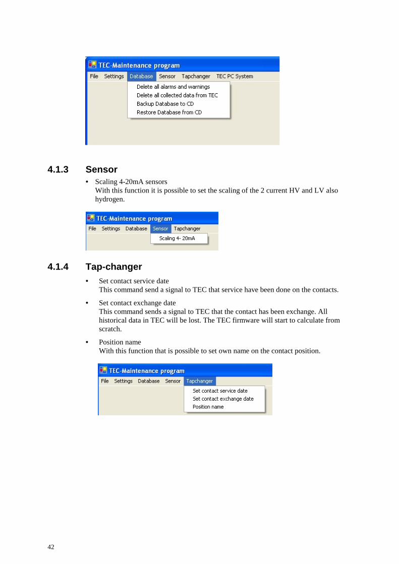
4.1.3 Sensor • Scaling 4-20mA sensors
With this function it is possible to set the scaling of the 2 current HV and LV also hydrogen.
4.1.4 Tap-changer • Set contact service date
This command send a signal to TEC that service have been done on the contacts.
• Set contact exchange date This command sends a signal to TEC that the contact has been exchange. All historical data in TEC will be lost. The TEC firmware will start to calculate from scratch.
• Position name With this function that is possible to set own name on the contact position.

43
4.1.5 Set document path Open by click in the menu on Set document path.
• Choose which TEC the document belongs to. • Choose which object the document belongs to (transformer, tap-changer, bushing
etc.). • Choose what kind of document it is. (The structure is organized by level 0
IndustrialIT). • Browse and choose the document that will be bound to the menu in the web-
interface.

44
4.1.6 Video settings Open by click in the menu on Set video path.
• Choose which TEC the video belongs to. • Choose which object the video belongs to. (tap-changer). • Choose what kind of video it is. (The structure is organized by level 0 IndustrialIT). • Browse and choose the video that will be bound to the menu in the web interface.
4.1.7 Select language • Copy the new XML-file into this path “C:\inetpub\wwwroot\tecwebsolution\NLS”
• Open by clicking Select language.
• Browse and select the new XML-file. • Click on Apply. • Restart the PC, the web interface must load the XML-file.

45
4.1.8 Delete all alarms and warnings This command deletes all alarms and warnings in the database. All historic alarms and warnings will be lost. It is not possible to undo this action.
If successful, a message box will appear.
4.1.9 Delete all collected data from TEC database This command deletes all collected data in the database. It is not possible to undo this action.
If successful, a message box will appear.
4.1.10 Backup the database to CD-RW This command takes a backup of the whole database. Use a CD/RW disc to do this. Place a CD/RW disc into the CD-holder before running the backup-command. This command does not delete anything in the database.
When performing the backup a black command-window appears. Follow the directions given by the program. Restart the TEC Maintenance program when the backup is completed.
4.1.11 Restore the TEC database This command will restore the TEC database from a CD/RW disc. Place the CD/RW disc into the CD-holder before running the restore-command.
When performing the backup a black command-window appears. Follow the directions given by the program. Restart the TEC Maintenance program when the backup is completed.

46
4.1.12 Scaling 4-20 mA sensors Open the scaling window by click in the menu Sensors. • Choose which TEC the scaling will be done at. • Click on OK. Now the current scaling is loaded from TEC. This can take a while. • When the scaling values appear then it is possible to change the scaling parameters
by click on [Edit].
• Click on Apply to set the new values.
Warning
When changing the scaling on HV and LV current measurement, be observant of if TEC has trip-signal on hot-spot since this can trip the transformer.
4.1.13 Set contact service date • Choose which TEC that the tap-changer belongs to.
• Click OK
When this command is executed the time to service in TEC is set to zero.

47
4.1.14 Set contact exchange date • Choose which TEC that the tap-changer belongs to.
• Click OK.
When this command is executed the time to service and time to exchange in TEC are set to zero.
4.1.15 Start and Stop services To avoid restart the PC, stop the services and start them again.

48
4.1.16 Position name This tool gives the possibilities to set own names on the contact positions. We recommend 3-4 characters.
• Choose which TEC the new position-name will be set on. • Click on Load.
The column Position is the static names. Write the own names in the right column. • Click on Apply when finished.

4.2 Guide for troubleshooting the TEC-system
4.2.1 Station PC 1. Open TEC Monitor, view Transformer temperature and look at last timestamp in
the database. (TEC Monitor saves values to the database every 5 minutes.)
2. Restart the PC and wait for 5 minutes. Check that the new values are stored according to step 1.
• If there still are no new values in the database, there is a communication failure between TEC and the station interface (station PC).
• If you already have new values in the database, the service that updates the database has stopped.
3. Check communication equipment (green RS 232/fiber converter box). There are tree LEDs (lights)
• VCC = green, indicates if you have power (24 V)
• TX = green, indicates communication from PC to TEC (blinks very seldom)
• RX = yellow, indicates communication from TEC to PC
VCC should constantly be green when the power is turned on. If it is not green, check the 24 V supply.
RX not blinking indicates that the TEC is not communicating.
If VCC is green and RX blinking, it must be a problem with the connection cable (Nullmodem-cable between PC and green box) or with the station PC. Check that the fiber cable is correctly connected at both ends.

50
4.2.2 TEC cabinet
1. Is the display working? Push the button. Is the display working now?
• YES. Compare the display temperature with the transformer sensor temperature.
• NO. Go to next step.
2. Open the cabinet and check the LEDs (lights) on TC120. Green or red?
a. Green. The program is running.
b. The LEDs are pending between red and green (5 second intervals). See step d.
c. Red. The program has stalled. Go to next step.
d. If both of the LEDs are black, the power supply TC110 is malfunctioning. Check the power supply to TC110. At least one of the two power supplies should work. (110 V and 240 V).
3. The program has stalled and needs to be restarted. Unplug the two cables (marked with red rings below) on the TC110 power supply and wait for 10 seconds.
Reconnect the two cables and TEC is now restarted. The LEDs on TC120 are red during initialization and then turn green when the application is started. If the LEDs do not turn green, the application has stalled.
4. If the green and red LEDs are still flashing after power reset, there is an application or hardware malfunction, and the system board TC120 needs to be changed.

51
5 Contact list In case of problems with TEC, contact the transformer manufacturer or:
ABB Power Technologies AB
Components
SE-771 80 LUDVIKA, Sweden
Phone +46 240 78 20 00
Fax +46 240 121 57
E-mail: [email protected]