type - armatec com · item component remarks type 4623 type 4622 type 4624 1 base / inlet body...
TRANSCRIPT
07/01LWN 481.01-E
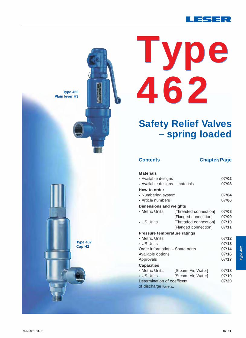
Type 462 Safety Relief Valves – spring loaded
Contents Chapter/Page
Materials • Available designs 07/02 • Available designs – materials 07/03
How to order
• Numbering system 07/04 • Article numbers 07/06
Dimensions and weights • Metric Units [Threaded connection] 07/08 [Flanged connection] 07/09 • US Units [Threaded connection] 07/10 [Flanged connection] 07/11
Pressure temperature ratings • Metric Units 07/12 • US Units 07/13 Order information – Spare parts 07/14 Available options 07/16 Approvals 07/17
Capacities • Metric Units [Steam, Air, Water] 07/18 • US Units [Steam, Air, Water] 07/19 Determination of coefficent 07/20 of discharge Kdr /αw
Type 462
Type 462Cap H2
Type 462Plain lever H3
Typ
e 46
2
07/06 LWN 481.01-E
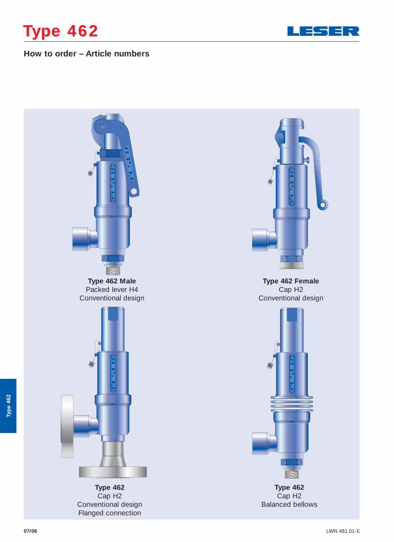
Type 462 MalePacked lever H4
Conventional design
Type 462 FemaleCap H2
Conventional design
Type 462 Cap H2
Conventional designFlanged connection
Type 462 Cap H2
Balanced bellows
How to order – Article numbers
Type 462Type 462
Typ
e 46
2

07/07LWN 481.01-E
Article numbers
O-ring material NBR “N” J30
CR “K” J21
EPDM “D” J22
FKM “L” J23
FFKM “C” J20
Actual Orifi ce diameter d0 [mm] 9 13 17,5
Actual Orifi ce area A0 [mm2] 63,9 133 241
Actual Orifi ce diameter d0 [inch] 0,354 0,512 0,689
Actual Orifi ce area A0 [inch2] 0,099 0,206 0,374 Outlet chamber casted
Inlet body 1.4104 H2 Art.-No. 4623. 2902 2912 2922
Outlet body 0.7043 H3 Art.-No. 4623. 2903 2913 2923
Bonnet 0.7043 H4 Art.-No. 4623. 2904 2914 2924
p [barg]S/G/L
0,5 – 250 0,5 – 180 0,5 – 92,5
p [psig] 7,3 – 3626 7,3 – 2911 7,3 – 1342 Outlet chamber deep-drawn
Inlet body 1.4404 H2 Art.-No. 4622. 3772 3782 3792
Outlet body 1.4404 H3 Art.-No. 4622. 3773 3783 3793
Bonnet 1.0460 H4 Art.-No. 4622. 3774 3784 3794
p [barg]S/G/L
0,5 – 250 0,5 – 180 0,5 – 92,5
p [psig] 7,3 – 3626 7,3 – 2611 7,3 – 1342 Outlet chamber deep-drawn
All body andtrim parts
1.4404 H2 Art.-No. 4624. 2952 2962 2972
H4 Art.-No. 4624. 2954 2964 2974
p [barg]S/G/L
0,5 – 250 0,5 – 180 0,5 – 92,5
p [psig] 7,3 – 3626 7,3 – 2611 7,3 – 1342
How to order – Article numbers
Type 462Type 462
For selection of inlet and outlet connection please refer to page 09/06 – 09/07.
Typ
e 46
2
07/02 LWN 481.01-E
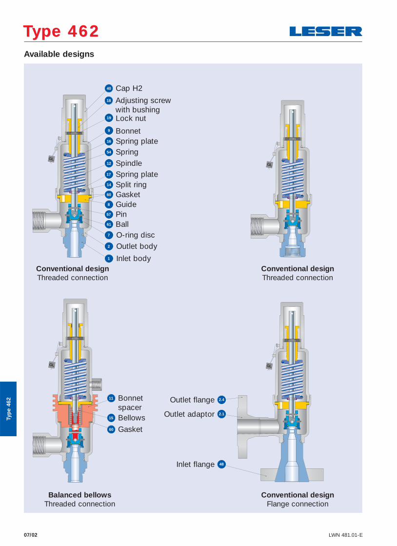
Type 462Type 462Available designs
18 Adjusting screw with bushing
40 Cap H2
19 Lock nut
12 Spindle
54 Spring
8 Guide
61 Ball
1 Inlet body
9 Bonnet
17 Spring plate14 Split ring60 Gasket
57 Pin
2 Outlet body
7 O-ring disc
16 Spring plate
11 Bonnetspacer
60 Gasket
15 Bellows Outlet adaptor 2.1
Outlet flange 2.4
Inlet flange 48
Typ
e 46
2
Balanced bellowsThreaded connection
Conventional designFlange connection
Conventional designThreaded connection
Conventional designThreaded connection
07/03LWN 481.01-E
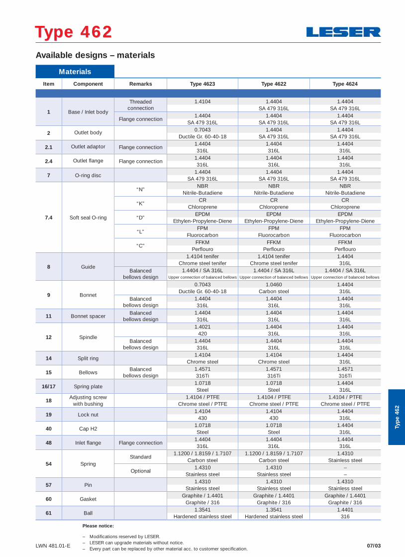
Materials
Item Component Remarks Type 4623 Type 4622 Type 4624
1 Base / Inlet body
Threadedconnection
1.4104 1.4404 1.4404 SA 479 316L SA 479 316L
Flange connection1.4404 1.4404 1.4404
SA 479 316L SA 479 316L SA 479 316L
2 Outlet body 0.7043 1.4404 1.4404Ductile Gr. 60-40-18 SA 479 316L SA 479 316L
2.1 Outlet adaptor Flange connection1.4404 1.4404 1.4404316L 316L 316L
2.4 Outlet fl ange Flange connection1.4404 1.4404 1.4404316L 316L 316L
7 O-ring disc1.4404 1.4404 1.4404
SA 479 316L SA 479 316L SA 479 316L
7.4 Soft seal O-ring
“N”NBR NBR NBR
Nitrile-Butadiene Nitrile-Butadiene Nitrile-Butadiene
“K”CR CR CR
Chloroprene Chloroprene Chloroprene
“D”EPDM EPDM EPDM
Ethylen-Propylene-Diene Ethylen-Propylene-Diene Ethylen-Propylene-Diene
“L”FPM FPM FPM
Fluorocarbon Fluorocarbon Fluorocarbon
“C”FFKM FFKM FFKM
Perfl ouro Perfl ouro Perfl ouro
8 Guide
1.4104 tenifer 1.4104 tenifer 1.4404Chrome steel tenifer Chrome steel tenifer 316L
Balanced bellows design
1.4404 / SA 316L 1.4404 / SA 316L 1.4404 / SA 316LUpper connection of balanced bellows Upper connection of balanced bellows Upper connection of balanced bellows
9 Bonnet
0.7043 1.0460 1.4404Ductile Gr. 60-40-18 Carbon steel 316L
Balanced bellows design
1.4404 1.4404 1.4404316L 316L 316L
11 Bonnet spacerBalanced
bellows design1.4404 1.4404 1.4404316L 316L 316L
12 Spindle
1.4021 1.4404 1.4404420 316L 316L
Balanced bellows design
1.4404 1.4404 1.4404316L 316L 316L
14 Split ring1.4104 1.4104 1.4404
Chrome steel Chrome steel 316L
15 BellowsBalanced
bellows design1.4571 1.4571 1.4571316Ti 316Ti 316Ti
16/17 Spring plate1.0718 1.0718 1.4404Steel Steel 316L
18Adjusting screw
with bushing1.4104 / PTFE 1.4104 / PTFE 1.4104 / PTFE
Chrome steel / PTFE Chrome steel / PTFE Chrome steel / PTFE
19 Lock nut1.4104 1.4104 1.4404
430 430 316L
40 Cap H21.0718 1.0718 1.4404Steel Steel 316L
48 Inlet fl ange Flange connection1.4404 1.4404 1.4404316L 316L 316L
54 SpringStandard
1.1200 / 1.8159 / 1.7107 1.1200 / 1.8159 / 1.7107 1.4310Carbon steel Carbon steel Stainless steel
Optional1.4310 1.4310 –
Stainless steel Stainless steel –
57 Pin1.4310 1.4310 1.4310
Stainless steel Stainless steel Stainless steel
60 GasketGraphite / 1.4401 Graphite / 1.4401 Graphite / 1.4401
Graphite / 316 Graphite / 316 Graphite / 316
61 Ball1.3541 1.3541 1.4401
Hardened stainless steel Hardened stainless steel 316
Available designs – materials
Type 462Type 462
Typ
e 46
2
Please notice:
– Modifications reserved by LESER.– LESER can upgrade materials without notice.– Every part can be replaced by other material acc. to customer specification.
07/08 LWN 481.01-E
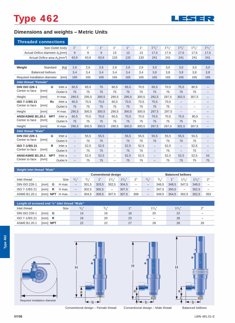
Dimensions and weights – Metric Units
Type 462Type 462
Conventional design – Female thread Conventional design – Male thread
c
Balanced bellows
cRequired installation diameter
Typ
e 46
2
Height inlet thread “Male”
Conventional design Balanced bellows
Inlet thread Size 1/2" 3/4" 1" 11/4" 11/2" 2" 1/2" 3/4" 1" 11/4" 11/2" 2"
DIN ISO 228-1 [mm] G H max. – 301,5 303,5 302,5 304,5 – – 346,5 348,5 347,5 349,5 –
ISO 7-1/BS 21 [mm] R H max. – 302,5 305,5 – 307,5 – – 347,5 350,5 – 352,5 –
ASME B1.20.1 [mm] NPT H max. – 304,5 309,5 307,5 307,5 308 – 349,5 354,5 352,5 352,5 353
Length of screwed end “c” inlet thread “Male”
Inlet thread Size 1/2" 3/4" 1" 11/4" 11/2" 2"
DIN ISO 228-1 [mm] G 14 16 18 20 22 –
ISO 7-1/BS 21 [mm] R 19 20 23 – 28 –
ASME B1.20.1 [mm] NPT 22 22 27 28 28 28
Threaded connections
Size Outlet body 1" 1" 1" 1" 1" 1" 11/2" 11/2" 11/2" 11/2" 11/2"
Actual Orifice diameter d0 [mm] 9 9 9 13 13 13 17,5 17,5 17,5 17,5 17,5
Actual Orifi ce area A0 [mm2] 63,6 63,6 63,6 133 133 133 241 241 241 241 241
Weight Standard [kg] 2,6 2,6 2,6 2,6 2,6 2,6 3,0 3,0 3,0 3,0 3,0
Balanced bellows 3,4 3,4 3,4 3,4 3,4 3,4 3,8 3,8 3,8 3,8 3,8
Required installation diameter [mm] 165 165 165 165 165 165 165 165 165 165 165
Inlet thread “Female”
DIN ISO 228-1 G Inlet a 60,5 65,5 70 60,5 65,5 70,5 65,5 70,5 75,5 80,5 –Center to face [mm] Outlet b 75 75 75 75 75 75 75 75 75 75 –
Height [mm] H max. 290,5 295,5 300,5 290,5 295,5 300,5 292,5 297,5 302,5 307,5 –
ISO 7-1/BS 21 Rc Inlet a 60,5 70,5 70,5 60,5 70,5 70,5 70,5 70,5 – – –Center to face [mm] Outlet b 75 75 75 75 75 75 75 75 – – –
Height [mm] H max. 290,5 300,5 300,5 290,5 300,5 300,5 297,5 297,5 – – –
ANSI/ASME B1.20.1 NPT Inlet a 60,5 70,5 70,5 60,5 70,5 70,5 70,5 70,5 75,5 80,5 –Center to face [mm] Outlet b 75 75 75 75 75 75 75 75 75 75 –
Height [mm] H max. 290,5 300,5 300,5 290,5 300,5 300,5 297,5 297,5 302,5 307,5 –
Inlet thread “Male”
DIN ISO 228-1 G Inlet a – 55,5 55,5 – 55,5 55,5 55,5 55,5 55,5 55,5 –Center to face [mm] Outlet b – 75 75 – 75 75 75 75 75 75 –
ISO 7-1/BS 21 R Inlet a – 52,5 52,5 – 52,5 52,5 – 52,5 – 52,5 –Center to face [mm] Outlet b – 75 75 – 75 75 – 75 – 75 –
ANSI/ASME B1.20.1 NPT Inlet a – 52,5 52,5 – 52,5 52,5 – 52,5 52,5 52,5 53Center to face [mm] Outlet b – 75 75 – 75 75 – 75 75 75 75
07/09LWN 481.01-E
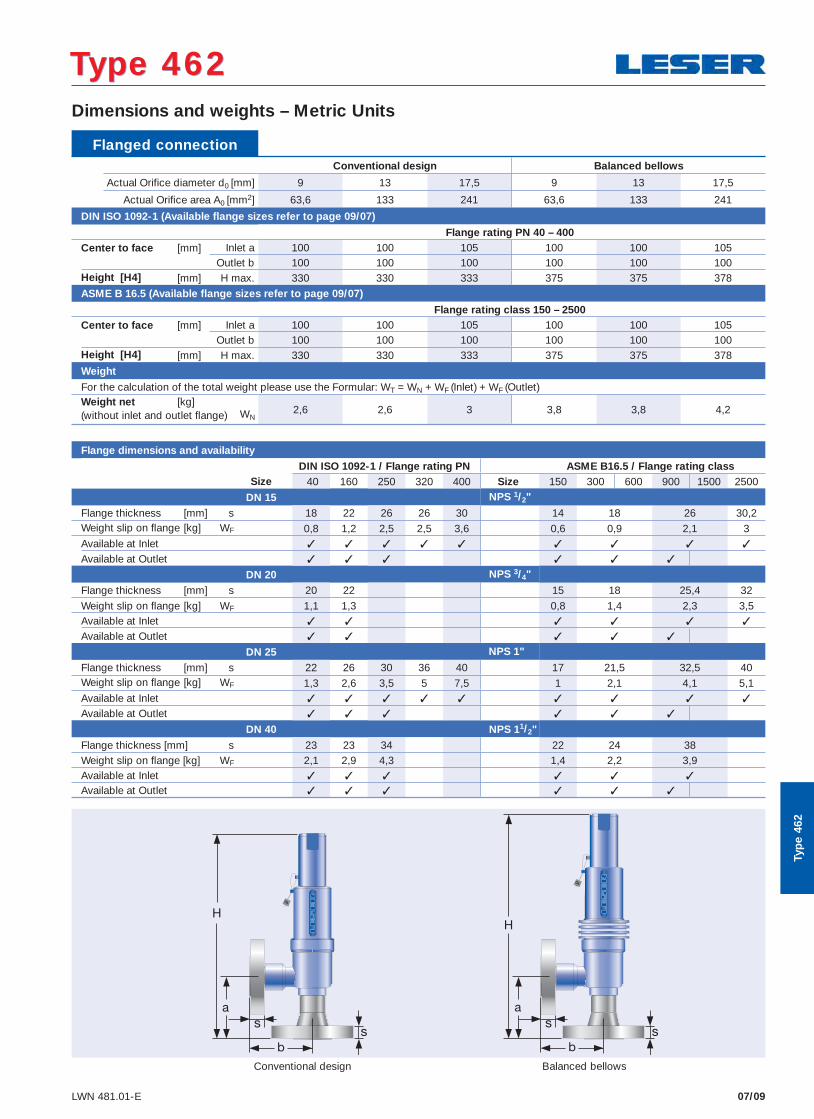
Flanged connection Conventional design Balanced bellows Actual Orifice diameter d0 [mm] 9 13 17,5 9 13 17,5
Actual Orifi ce area A0 [mm2] 63,6 133 241 63,6 133 241
DIN ISO 1092-1 (Available fl ange sizes refer to page 09/07)
Flange rating PN 40 – 400Center to face [mm] Inlet a 100 100 105 100 100 105
Outlet b 100 100 100 100 100 100Height [H4] [mm] H max. 330 330 333 375 375 378ASME B 16.5 (Available fl ange sizes refer to page 09/07)
Flange rating class 150 – 2500Center to face [mm] Inlet a 100 100 105 100 100 105
Outlet b 100 100 100 100 100 100Height [H4] [mm] H max. 330 330 333 375 375 378
Weight
For the calculation of the total weight please use the Formular: WT = WN + WF (Inlet) + WF (Outlet)Weight net [kg]
2,6 2,6 3 3,8 3,8 4,2(without inlet and outlet fl ange) WN
Flange dimensions and availability DIN ISO 1092-1 / Flange rating PN ASME B16.5 / Flange rating class
Size 40 160 250 320 400 Size 150 300 600 900 1500 2500
DN 15 NPS 1/2"
Flange thickness [mm] s 18 22 26 26 30 14 18 26 30,2Weight slip on fl ange [kg] WF 0,8 1,2 2,5 2,5 3,6 0,6 0,9 2,1 3Available at Inlet ✓ ✓ ✓ ✓ ✓ ✓ ✓ ✓ ✓
Available at Outlet ✓ ✓ ✓ ✓ ✓ ✓
DN 20 NPS 3/4"
Flange thickness [mm] s 20 22 15 18 25,4 32
Weight slip on fl ange [kg] WF 1,1 1,3 0,8 1,4 2,3 3,5Available at Inlet ✓ ✓ ✓ ✓ ✓ ✓
Available at Outlet ✓ ✓ ✓ ✓ ✓
DN 25 NPS 1"
Flange thickness [mm] s 22 26 30 36 40 17 21,5 32,5 40Weight slip on fl ange [kg] WF 1,3 2,6 3,5 5 7,5 1 2,1 4,1 5,1Available at Inlet ✓ ✓ ✓ ✓ ✓ ✓ ✓ ✓ ✓
Available at Outlet ✓ ✓ ✓ ✓ ✓ ✓
DN 40 NPS 11/2"
Flange thickness [mm] s 23 23 34 22 24 38Weight slip on fl ange [kg] WF 2,1 2,9 4,3 1,4 2,2 3,9 Available at Inlet ✓ ✓ ✓ ✓ ✓ ✓
Available at Outlet ✓ ✓ ✓ ✓ ✓ ✓
Dimensions and weights – Metric Units
Type 462Type 462
Typ
e 46
2
Balanced bellowsConventional design
07/12 LWN 481.01-E
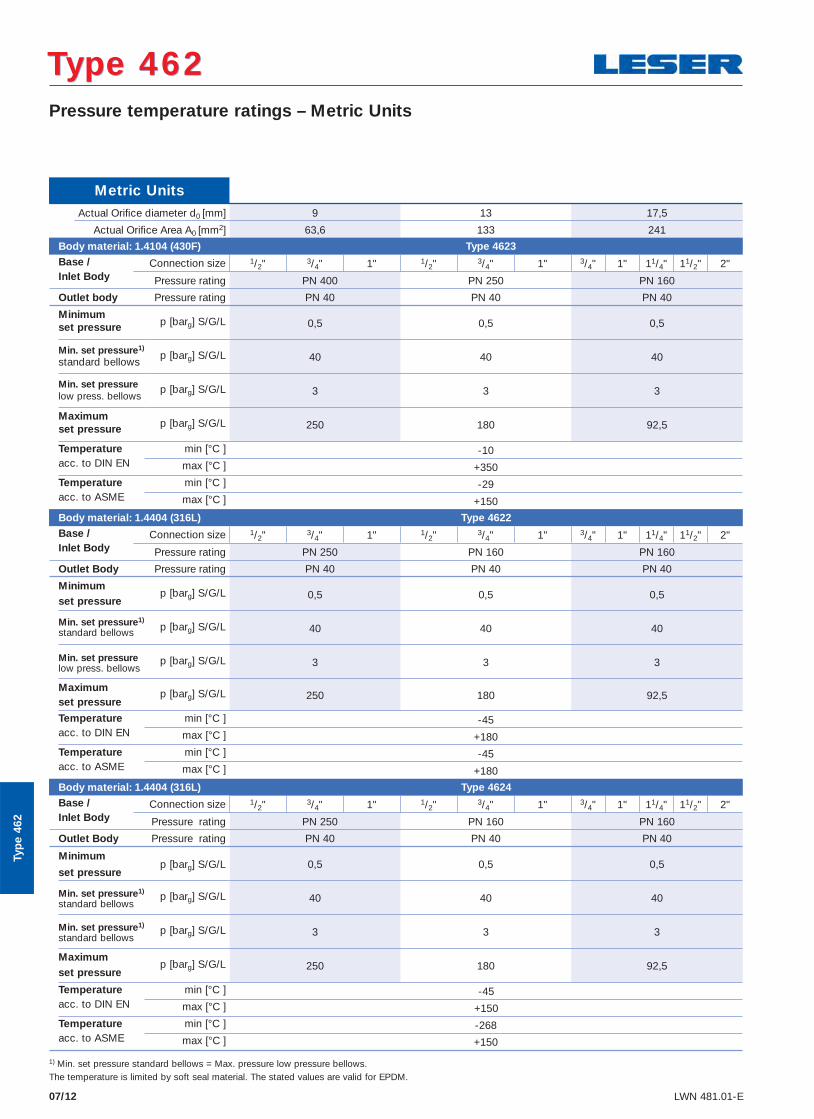
Metric Units Actual Orifi ce diameter d0 [mm] 9 13 17,5
Actual Orifi ce Area A0 [mm2] 63,6 133 241 Body material: 1.4104 (430F) Type 4623
Base / Connection size 1/2" 3/4" 1" 1/2" 3/4" 1" 3/4" 1" 11/4" 11/2" 2" Inlet Body Pressure rating PN 400 PN 250 PN 160
Outlet body Pressure rating PN 40 PN 40 PN 40
Minimump [barg] S/G/L 0,5 0,5 0,5 set pressure
Min. set pressure1) standard bellows
p [barg] S/G/L 40 40 40
Min. set pressure low press. bellows
p [barg] S/G/L 3 3 3
Maximum p [barg] S/G/L 250 180 92,5set pressure
Temperature min [°C ] -10acc. to DIN EN max [°C ] +350
Temperature min [°C ] -29acc. to ASME max [°C ] +150
Body material: 1.4404 (316L) Type 4622Base / Connection size 1/2" 3/4" 1" 1/2" 3/4" 1" 3/4" 1" 11/4" 11/2" 2"Inlet Body Pressure rating PN 250 PN 160 PN 160
Outlet Body Pressure rating PN 40 PN 40 PN 40
Minimump [barg] S/G/L 0,5 0,5 0,5
set pressure
Min. set pressure1) standard bellows p [barg] S/G/L 40 40 40
Min. set pressure low press. bellows
p [barg] S/G/L 3 3 3
Maximum p [barg] S/G/L 250 180 92,5
set pressure
Temperature min [°C ] -45acc. to DIN EN max [°C ] +180Temperature min [°C ] -45acc. to ASME max [°C ] +180
Body material: 1.4404 (316L) Type 4624Base / Connection size 1/2" 3/4" 1" 1/2" 3/4" 1" 3/4" 1" 11/4" 11/2" 2"Inlet Body Pressure rating PN 250 PN 160 PN 160
Outlet Body Pressure rating PN 40 PN 40 PN 40
Minimump [barg] S/G/L 0,5 0,5 0,5
set pressure
Min. set pressure1) standard bellows
p [barg] S/G/L 40 40 40
Min. set pressure1) standard bellows
p [barg] S/G/L 3 3 3
Maximum p [barg] S/G/L 250 180 92,5
set pressure
Temperature min [°C ] -45acc. to DIN EN max [°C ] +150Temperature min [°C ] -268acc. to ASME max [°C ] +150
Pressure temperature ratings – Metric Units
Type 462Type 462
Typ
e 46
2
1) Min. set pressure standard bellows = Max. pressure low pressure bellows.The temperature is limited by soft seal material. The stated values are valid for EPDM.
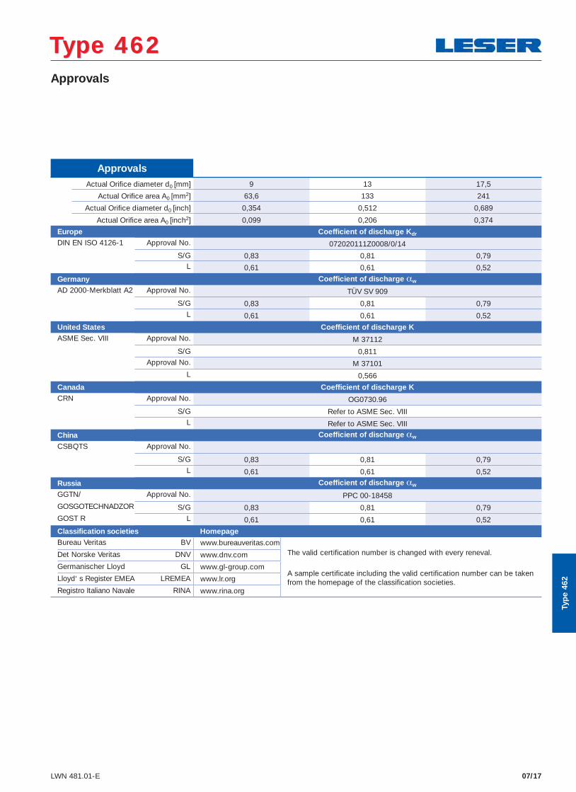
Approvals Actual Orifi ce diameter d0 [mm] 9 13 17,5
Actual Orifi ce area A0 [mm2] 63,6 133 241
Actual Orifi ce diameter d0 [inch] 0,354 0,512 0,689
Actual Orifi ce area A0 [inch2] 0,099 0,206 0,374 Europe Coefficient of discharge Kdr
DIN EN ISO 4126-1 Approval No. 072020111Z0008/0/14
S/G 0,83 0,81 0,79L 0,61 0,61 0,52
Germany Coefficient of discharge αw
AD 2000-Merkblatt A2 Approval No. TÜV SV 909
S/G 0,83 0,81 0,79L 0,61 0,61 0,52
United States Coefficient of discharge KASME Sec. VIII Approval No. M 37112
S/G 0,811Approval No. M 37101
L 0,566 Canada Coefficient of discharge K
CRN Approval No. OG0730.96
S/G Refer to ASME Sec. VIIIL Refer to ASME Sec. VIII
China Coefficient of discharge αw
CSBQTS Approval No.
S/G 0,83 0,81 0,79L 0,61 0,61 0,52
Russia Coefficient of discharge αw
GGTN/ Approval No. PPC 00-18458GOSGOTECHNADZOR S/G 0,83 0,81 0,79GOST R L 0,61 0,61 0,52
Classification societies Homepage
Bureau Veritas BV www.bureauveritas.comThe valid certification number is changed with every reneval.
A sample certificate including the valid certification number can be taken from the homepage of the classification societies.
Det Norske Veritas DNV www.dnv.com
Germanischer Lloyd GL www.gl-group.com
Lloyd‘ s Register EMEA LREMEA www.lr.org
Registro Italiano Navale RINA www.rina.org
07/17LWN 481.01-E
Approvals
Type 462Type 462
Typ
e 46
2
07/18 LWN 481.01-E
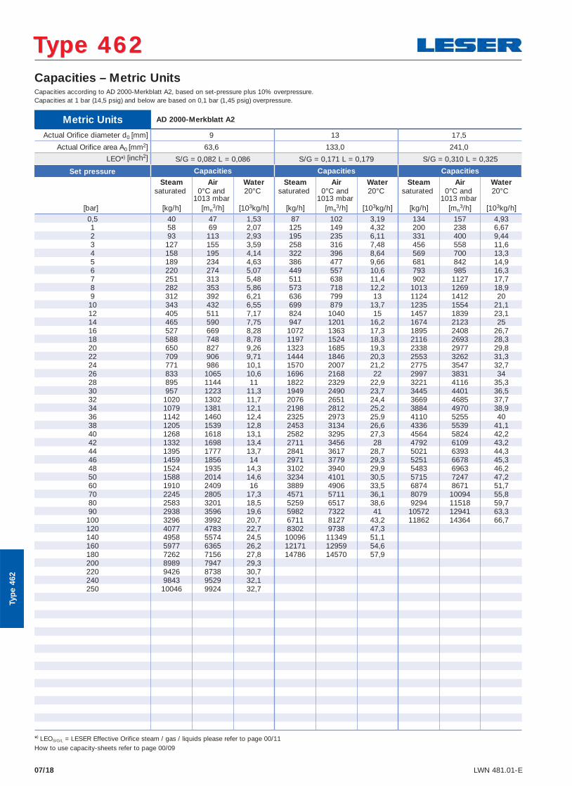
Capacities – Metric Units
Metric Units AD 2000-Merkblatt A2
Actual Orifice diameter d0 [mm] 9 13 17,5
Actual Orifice area A0 [mm2] 63,6 133,0 241,0
LEO*) [inch2] S/G = 0,082 L = 0,086 S/G = 0,171 L = 0,179 S/G = 0,310 L = 0,325
Capacities according to AD 2000-Merkblatt A2, based on set-pressure plus 10% overpressure.Capacities at 1 bar (14,5 psig) and below are based on 0,1 bar (1,45 psig) overpressure.
Set pressure Capacities Capacities Capacities
Steam Air Water Steam Air Water Steam Air Watersaturated 0°C and
1013 mbar20°C saturated 0°C and
1013 mbar20°C saturated 0°C and
1013 mbar20°C
[bar] [kg/h] [mn3/h] [103kg/h] [kg/h] [mn
3/h] [103kg/h] [kg/h] [mn3/h] [103kg/h]
0,5 40 47 1,53 87 102 3,19 134 157 4,93 1 58 69 2,07 125 149 4,32 200 238 6,67 2 93 113 2,93 195 235 6,11 331 400 9,44 3 127 155 3,59 258 316 7,48 456 558 11,6 4 158 195 4,14 322 396 8,64 569 700 13,3 5 189 234 4,63 386 477 9,66 681 842 14,9 6 220 274 5,07 449 557 10,6 793 985 16,3 7 251 313 5,48 511 638 11,4 902 1127 17,7 8 282 353 5,86 573 718 12,2 1013 1269 18,9 9 312 392 6,21 636 799 13 1124 1412 20 10 343 432 6,55 699 879 13,7 1235 1554 21,1 12 405 511 7,17 824 1040 15 1457 1839 23,1 14 465 590 7,75 947 1201 16,2 1674 2123 25 16 527 669 8,28 1072 1363 17,3 1895 2408 26,7 18 588 748 8,78 1197 1524 18,3 2116 2693 28,3 20 650 827 9,26 1323 1685 19,3 2338 2977 29,8 22 709 906 9,71 1444 1846 20,3 2553 3262 31,3 24 771 986 10,1 1570 2007 21,2 2775 3547 32,7 26 833 1065 10,6 1696 2168 22 2997 3831 34 28 895 1144 11 1822 2329 22,9 3221 4116 35,3 30 957 1223 11,3 1949 2490 23,7 3445 4401 36,5 32 1020 1302 11,7 2076 2651 24,4 3669 4685 37,7 34 1079 1381 12,1 2198 2812 25,2 3884 4970 38,9 36 1142 1460 12,4 2325 2973 25,9 4110 5255 40 38 1205 1539 12,8 2453 3134 26,6 4336 5539 41,1 40 1268 1618 13,1 2582 3295 27,3 4564 5824 42,2 42 1332 1698 13,4 2711 3456 28 4792 6109 43,2 44 1395 1777 13,7 2841 3617 28,7 5021 6393 44,3 46 1459 1856 14 2971 3779 29,3 5251 6678 45,3 48 1524 1935 14,3 3102 3940 29,9 5483 6963 46,2 50 1588 2014 14,6 3234 4101 30,5 5715 7247 47,2 60 1910 2409 16 3889 4906 33,5 6874 8671 51,7 70 2245 2805 17,3 4571 5711 36,1 8079 10094 55,8 80 2583 3201 18,5 5259 6517 38,6 9294 11518 59,7 90 2938 3596 19,6 5982 7322 41 10572 12941 63,3 100 3296 3992 20,7 6711 8127 43,2 11862 14364 66,7 120 4077 4783 22,7 8302 9738 47,3 140 4958 5574 24,5 10096 11349 51,1 160 5977 6365 26,2 12171 12959 54,6 180 7262 7156 27,8 14786 14570 57,9 200 8989 7947 29,3 220 9426 8738 30,7 240 9843 9529 32,1 250 10046 9924 32,7
Type 462Type 462
*) LEOS/G/L = LESER Effective Orifice steam / gas / liquids please refer to page 00/11How to use capacity-sheets refer to page 00/09
Typ
e 46
2
07/19 LWN 481.01-E
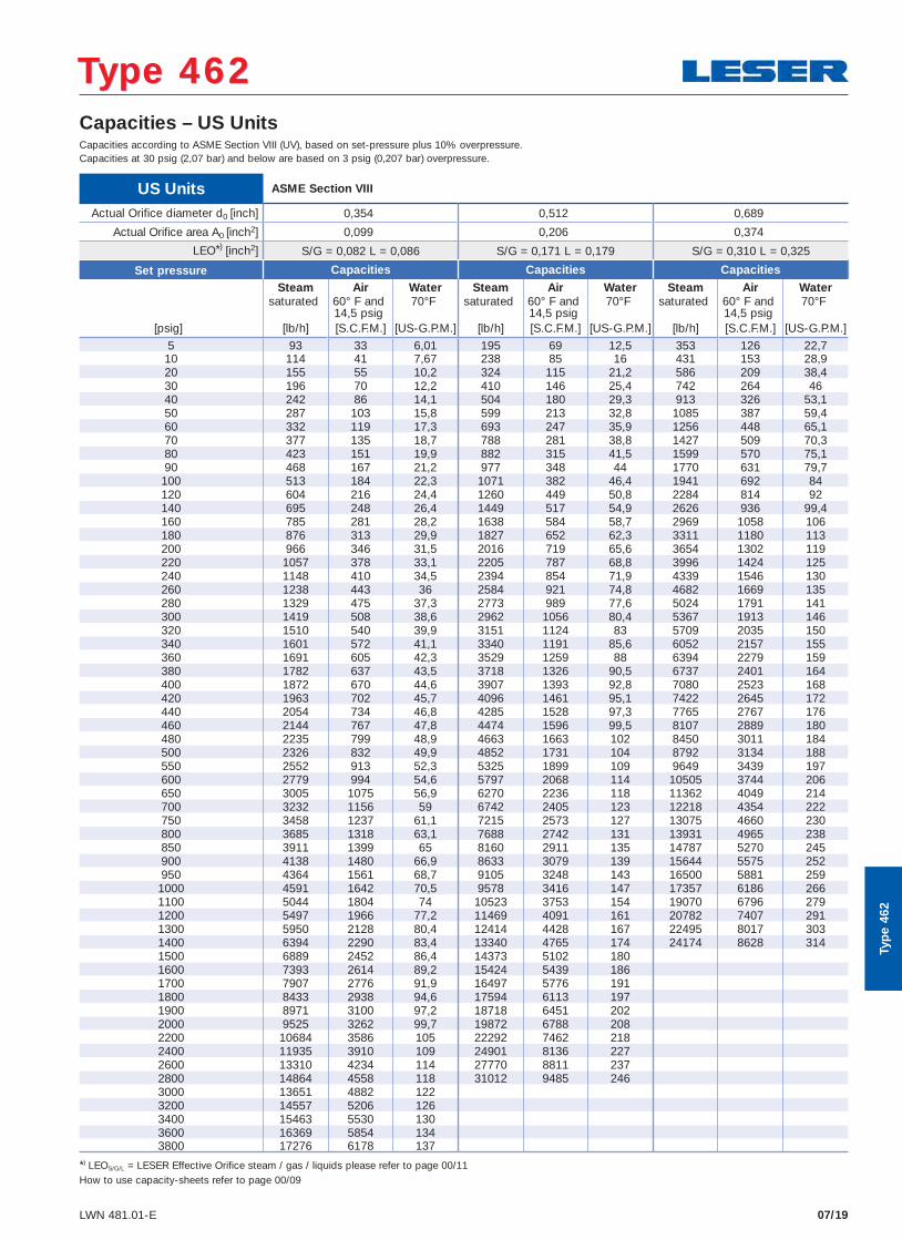
Capacities – US Units
US Units ASME Section VIII
Actual Orifice diameter d0 [inch] 0,354 0,512 0,689
Actual Orifice area A0 [inch2] 0,099 0,206 0,374
LEO*) [inch2] S/G = 0,082 L = 0,086 S/G = 0,171 L = 0,179 S/G = 0,310 L = 0,325
Capacities according to ASME Section VIII (UV), based on set-pressure plus 10% overpressure.Capacities at 30 psig (2,07 bar) and below are based on 3 psig (0,207 bar) overpressure.
Set pressure Capacities Capacities Capacities
Steam Air Water Steam Air Water Steam Air Watersaturated 60° F and
14,5 psig70°F saturated 60° F and
14,5 psig70°F saturated 60° F and
14,5 psig70°F
[psig] [lb/h] [S.C.F.M.] [US-G.P.M.] [lb/h] [S.C.F.M.] [US-G.P.M.] [lb/h] [S.C.F.M.] [US-G.P.M.]
5 93 33 6,01 195 69 12,5 353 126 22,7 10 114 41 7,67 238 85 16 431 153 28,9 20 155 55 10,2 324 115 21,2 586 209 38,4 30 196 70 12,2 410 146 25,4 742 264 46 40 242 86 14,1 504 180 29,3 913 326 53,1 50 287 103 15,8 599 213 32,8 1085 387 59,4 60 332 119 17,3 693 247 35,9 1256 448 65,1 70 377 135 18,7 788 281 38,8 1427 509 70,3 80 423 151 19,9 882 315 41,5 1599 570 75,1 90 468 167 21,2 977 348 44 1770 631 79,7 100 513 184 22,3 1071 382 46,4 1941 692 84 120 604 216 24,4 1260 449 50,8 2284 814 92 140 695 248 26,4 1449 517 54,9 2626 936 99,4 160 785 281 28,2 1638 584 58,7 2969 1058 106 180 876 313 29,9 1827 652 62,3 3311 1180 113 200 966 346 31,5 2016 719 65,6 3654 1302 119 220 1057 378 33,1 2205 787 68,8 3996 1424 125 240 1148 410 34,5 2394 854 71,9 4339 1546 130 260 1238 443 36 2584 921 74,8 4682 1669 135 280 1329 475 37,3 2773 989 77,6 5024 1791 141 300 1419 508 38,6 2962 1056 80,4 5367 1913 146 320 1510 540 39,9 3151 1124 83 5709 2035 150 340 1601 572 41,1 3340 1191 85,6 6052 2157 155 360 1691 605 42,3 3529 1259 88 6394 2279 159 380 1782 637 43,5 3718 1326 90,5 6737 2401 164 400 1872 670 44,6 3907 1393 92,8 7080 2523 168 420 1963 702 45,7 4096 1461 95,1 7422 2645 172 440 2054 734 46,8 4285 1528 97,3 7765 2767 176 460 2144 767 47,8 4474 1596 99,5 8107 2889 180 480 2235 799 48,9 4663 1663 102 8450 3011 184 500 2326 832 49,9 4852 1731 104 8792 3134 188 550 2552 913 52,3 5325 1899 109 9649 3439 197 600 2779 994 54,6 5797 2068 114 10505 3744 206 650 3005 1075 56,9 6270 2236 118 11362 4049 214 700 3232 1156 59 6742 2405 123 12218 4354 222 750 3458 1237 61,1 7215 2573 127 13075 4660 230 800 3685 1318 63,1 7688 2742 131 13931 4965 238 850 3911 1399 65 8160 2911 135 14787 5270 245 900 4138 1480 66,9 8633 3079 139 15644 5575 252 950 4364 1561 68,7 9105 3248 143 16500 5881 259 1000 4591 1642 70,5 9578 3416 147 17357 6186 266 1100 5044 1804 74 10523 3753 154 19070 6796 279 1200 5497 1966 77,2 11469 4091 161 20782 7407 291 1300 5950 2128 80,4 12414 4428 167 22495 8017 303 1400 6394 2290 83,4 13340 4765 174 24174 8628 314 1500 6889 2452 86,4 14373 5102 180 1600 7393 2614 89,2 15424 5439 186 1700 7907 2776 91,9 16497 5776 191 1800 8433 2938 94,6 17594 6113 197 1900 8971 3100 97,2 18718 6451 202 2000 9525 3262 99,7 19872 6788 208 2200 10684 3586 105 22292 7462 218 2400 11935 3910 109 24901 8136 227 2600 13310 4234 114 27770 8811 237 2800 14864 4558 118 31012 9485 246 3000 13651 4882 122 3200 14557 5206 126 3400 15463 5530 130 3600 16369 5854 134 3800 17276 6178 137
Type 462Type 462
*) LEOS/G/L = LESER Effective Orifice steam / gas / liquids please refer to page 00/11How to use capacity-sheets refer to page 00/09
Typ
e 46
2
07/16 LWN 481.01-E
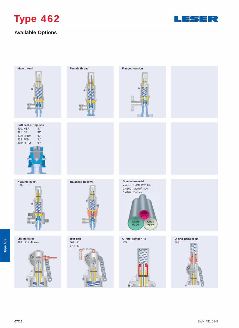
Available Options
Type 462Type 462
Typ
e 46
2
Heating jacket H29
Soft seal o-ring disc J30: NBR “N” J21: CR “K” J22: EPDM “D” J23: FKM “L” J20: FFKM “C”
Lift indicator J93: Lift indicator
Test gag J69: H4 J70: H2
O-ring-damper H2 J65
O-ring-damper H4 J66
Male thread Female thread Flanged version
Balanced bellows Special material 2.4610 Hastelloy® C4 2.4360 Monel® 400 1.4462 Duplex
CodeYYYY
CodeXXXX
CodeZZZZ
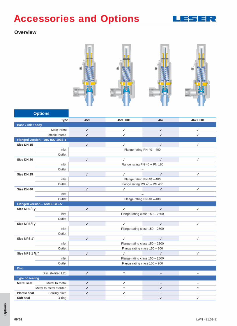
Overview
Accessories and OptionsAccessories and Options
09/02 LWN 481.01-E
OptionsType 459 459 HDD 462 462 HDD
Base / Inlet body
Male thread ✓ ✓ ✓ ✓
Female thread ✓ ✓ ✓ ✓
Flanged version – DIN ISO 1092-1
Size DN 15 ✓ ✓ ✓ ✓
Inlet Flange rating PN 40 – 400
Outlet –
Size DN 20 ✓ ✓ ✓ ✓
Inlet Flange rating PN 40 + PN 160
Outlet –
Size DN 25 ✓ ✓ ✓ ✓
Inlet Flange rating PN 40 – 400
Outlet Flange rating PN 40 – PN 400
Size DN 40 ✓ ✓ ✓ ✓
Inlet –
Outlet Flange rating PN 40 – 400
Flanged version – ASME B16.5
Size NPS 1/2" ✓ ✓ ✓ ✓
Inlet Flange rating class 150 – 2500
Outlet –
Size NPS 3/4" ✓ ✓ ✓ ✓
Inlet Flange rating class 150 – 2500
Outlet –
Size NPS 1" ✓ ✓ ✓ ✓
Inlet Flange rating class 150 – 2500
Outlet Flange rating class 150 – 900
Size NPS 1 1/2" ✓ ✓ ✓ ✓
Inlet Flange rating class 150 – 2500
Outlet Flange rating class 150 – 900
Disc
Disc stellited L25 ✓ * – –
Type of sealing
Metal seat Metal to metal ✓ ✓ – –
Metal to metal stellited ✓ * ✓ *Plastic seat Sealing plate ✓ ✓ – –
Soft seal O-ring – – ✓ ✓
Op
tio
ns

Accessories and OptionsAccessories and Options
09/03LWN 481.01-E
Overview
OptionsType 459 459 HDD 462 462 HDD
Caps and levers
H2 ✓ ✓ ✓ ✓
H3 ✓ – ✓ –
H4 ✓ ✓ ✓ ✓
Heating jacket
Outlet body ✓ ✓ ✓ ✓
Bonnet spacer ✓ ✓ ✓ ✓
Test gag
H2 ✓ ✓ ✓ ✓
H4 – – – –
Bellows
Stainless steel ✓ ✓ ✓ ✓
low pressure ✓ ✓ ✓ ✓
Hasteloy or spec. mat. ✓ ✓ ✓ ✓
High temp. equipment – ✓ – ✓
Elastomer ✓ – ✓ –
Lift indicator
Lifting device H4 ✓ ✓ ✓ ✓
Lift stopper
Bush ✓ ✓ except d0 6 mm ✓ ✓
Gag ✓ ✓ ✓ ✓
O-ring damper
H2 ✓ – ✓ –
H4 ✓ – ✓ –
Op
tio
ns
BLOCKEDRemove
after testing
Plain lever H3
Packed lever H4
Accessories and OptionsAccessories and Options
09/04 LWN 481.01-E
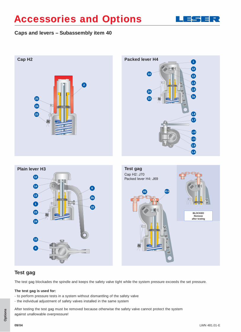
Caps and levers – Subassembly item 40
Cap H21
12
13
1.5
1.6
3a23
24
14
1.8
1.7
1.10
1.9
1.4
1.11
1
12
133b
23
24
146
22
10
4
Op
tio
ns
Test gag Cap H2: J70 Packed lever H4: J69
93.593
Test gag
The test gag blockades the spindle and keeps the safety valve tight while the system pressure exceeds the set pressure.
The test gag is used for: - to perform pressure tests in a system without dismantling of the safety valve- the individual adjustment of safety valves installed in the same system
After testing the test gag must be removed because otherwise the safety valve cannot protect the system against unallowable overpressure!
24
23
2
25
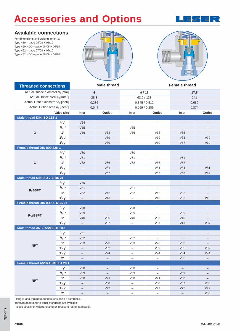
Available connections
Threaded connectionsActual Orifi ce diameter d0 [mm] 6 9 / 13 17,5
Actual Orifi ce area A0 [mm2] 28,3 63,9 / 133 241Actual Orifi ce diameter d0 [inch] 0,236 0,345 / 0,512 0,689
Actual Orifi ce area A0 [inch2] 0,044 0,099 / 0,206 0,374
Valve size Inlet Outlet Inlet Outlet Inlet Outlet
Male thread DIN ISO 228-1
G
1/2" V54 – – – – –3/4 " V55 – V55 – – –
1" V56 V68 V56 V68 V65 –
11/4" – V79 – V79 V83 V79
11/2" – V69 – V69 V57 V69
Female thread DIN ISO 228-1
G
1/2" V50 – V50 – – –3/4 " V51 – V51 – V51 –
1" V52 V66 V52 V66 V52 –
11/4" – V81 – V81 V84 V81
11/2" – V67 – V67 V53 V67
Male thread DIN ISO 7-1/BS 21
R/BSPT
1/2" V30 – – – – –3/4 " V31 – V31 – – –
1" V32 V42 V32 V42 V32 –
11/2" – V43 – V43 V33 V43
Female thread DIN ISO 7-1/BS 21
Rc/BSPT
1/2" V38 – V38 – – –3/4 " V39 – V39 – V39 –
1" V40 V36 V40 V36 V40 –
11/2" – V37 – V37 V41 V37
Male thread ANSI/ASME B1.20.1
NPT
1/2" V61 – – – – –3/4 " V62 – V62 – – –
1" V63 V73 V63 V73 V63 –
11/4" – V82 – V82 V85 V82
11/2" – V74 – V74 V64 V74
2" – – – – V86 –
Female thread ANSI/ASME B1.20.1
NPT
1/2" V58 – V58 – – –3/4 " V59 – V59 – V59 –
1" V60 V71 V60 V71 V60 –
11/4" – V80 – V80 V87 V80
11/2" – V72 – V72 V75 V72
2" – – – – – V88
Male thread Female thread
Accessories and OptionsAccessories and Options
09/06 LWN 481.01-E
Op
tio
ns
Flanged and threaded connections can be combined.Threads according to other standards are available.Please specify in writing (diameter, pressure rating, standard).
For dimensions and weights refer to:Type 459 – page 05/08 + 05/10Type 459 HDD – page 06/08 + 06/10Type 462 – page 07/08 + 07/10Type 462 HDD – page 08/08 + 08/10
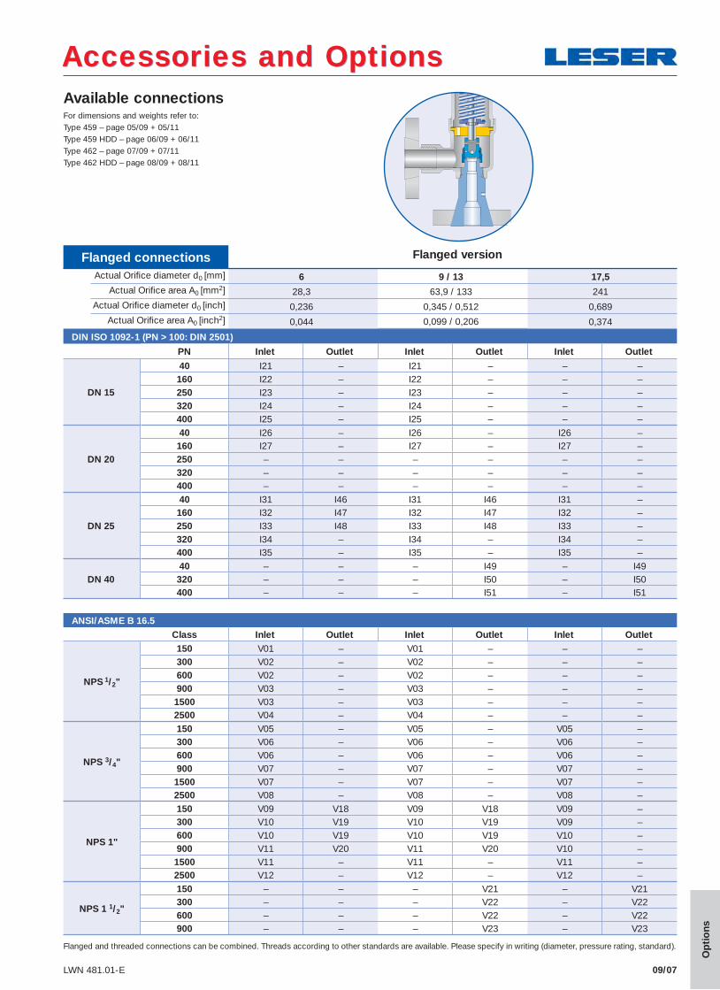
Available connections
Flanged connectionsActual Orifi ce diameter d0 [mm] 6 9 / 13 17,5
Actual Orifi ce area A0 [mm2] 28,3 63,9 / 133 241Actual Orifi ce diameter d0 [inch] 0,236 0,345 / 0,512 0,689
Actual Orifi ce area A0 [inch2] 0,044 0,099 / 0,206 0,374
DIN ISO 1092-1 (PN > 100: DIN 2501)
PN Inlet Outlet Inlet Outlet Inlet Outlet
DN 15
40 I21 – I21 – – –160 I22 – I22 – – –250 I23 – I23 – – –320 I24 – I24 – – –400 I25 – I25 – – –
DN 20
40 I26 – I26 – I26 –160 I27 – I27 – I27 –250 – – – – – –320 – – – – – –400 – – – – – –
DN 25
40 I31 I46 I31 I46 I31 –160 I32 I47 I32 I47 I32 –250 I33 I48 I33 I48 I33 –320 I34 – I34 – I34 –400 I35 – I35 – I35 –
DN 4040 – – – I49 – I49320 – – – I50 – I50400 – – – I51 – I51
ANSI/ASME B 16.5Class Inlet Outlet Inlet Outlet Inlet Outlet
NPS 1/2"
150 V01 – V01 – – –300 V02 – V02 – – –600 V02 – V02 – – –900 V03 – V03 – – –1500 V03 – V03 – – –2500 V04 – V04 – – –
NPS 3/4"
150 V05 – V05 – V05 –300 V06 – V06 – V06 –600 V06 – V06 – V06 –900 V07 – V07 – V07 –1500 V07 – V07 – V07 –2500 V08 – V08 – V08 –
NPS 1"
150 V09 V18 V09 V18 V09 –300 V10 V19 V10 V19 V09 –600 V10 V19 V10 V19 V10 –900 V11 V20 V11 V20 V10 –1500 V11 – V11 – V11 –2500 V12 – V12 – V12 –
NPS 1 1/2"
150 – – – V21 – V21300 – – – V22 – V22600 – – – V22 – V22900 – – – V23 – V23
Flanged version
Accessories and OptionsAccessories and Options
09/07LWN 481.01-E
Op
tio
ns
Flanged and threaded connections can be combined. Threads according to other standards are available. Please specify in writing (diameter, pressure rating, standard).
For dimensions and weights refer to:Type 459 – page 05/09 + 05/11Type 459 HDD – page 06/09 + 06/11Type 462 – page 07/09 + 07/11Type 462 HDD – page 08/09 + 08/11
Accessories and OptionsAccessories and Options
09/09LWN 481.01-E
Op
tio
ns
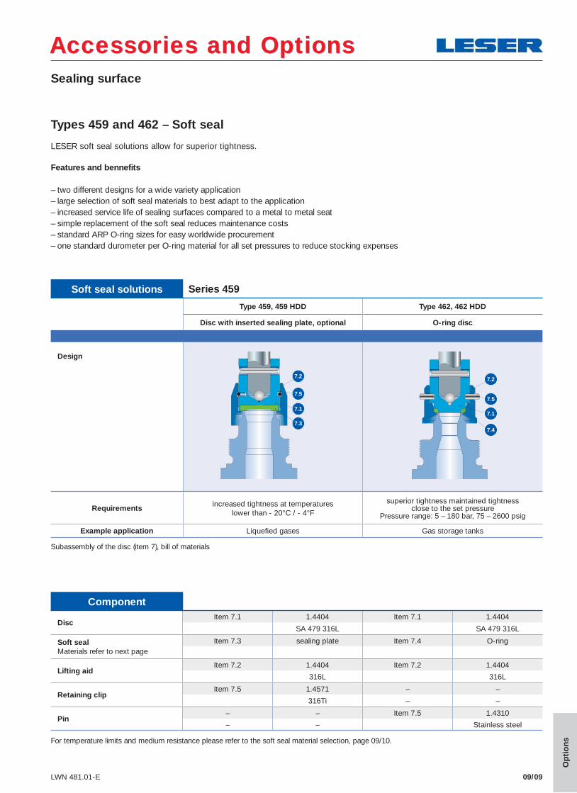
Types 459 and 462 – Soft seal
LESER soft seal solutions allow for superior tightness.
Features and bennefits
– two different designs for a wide variety application – large selection of soft seal materials to best adapt to the application – increased service life of sealing surfaces compared to a metal to metal seat – simple replacement of the soft seal reduces maintenance costs – standard ARP O-ring sizes for easy worldwide procurement – one standard durometer per O-ring material for all set pressures to reduce stocking expenses
Subassembly of the disc (item 7), bill of materials
DiscItem 7.1 1.4404 Item 7.1 1.4404
SA 479 316L SA 479 316L
Soft sealMaterials refer to next page
Item 7.3 sealing plate Item 7.4 O-ring
Lifting aidItem 7.2 1.4404 Item 7.2 1.4404
316L 316L
Retaining clipItem 7.5 1.4571 – –
316Ti – –
Pin– – Item 7.5 1.4310
– – Stainless steel
Component
Type 459, 459 HDD Type 462, 462 HDD
Disc with inserted sealing plate, optional O-ring disc
Design
Requirements increased tightness at temperatures lower than - 20°C / - 4°F
superior tightness maintained tightness close to the set pressure
Pressure range: 5 – 180 bar, 75 – 2600 psig
Example application Liquefi ed gases Gas storage tanks
Soft seal solutions Series 459
7.2
7.5
7.1
7.3
7.2
7.5
7.1
7.4
For temperature limits and medium resistance please refer to the soft seal material selection, page 09/10.
Sealing surface
09/10 LWN 480.01-E
Accessories and OptionsAccessories and Options
Op
tio
ns
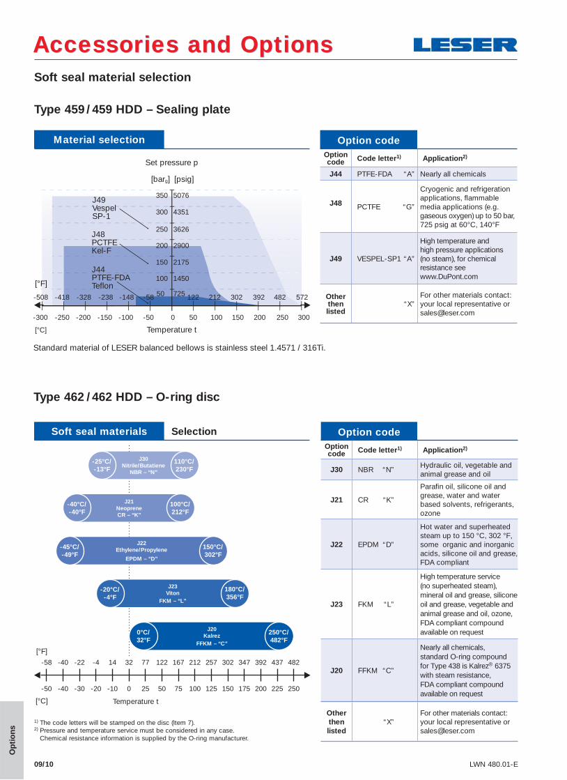
Soft seal material selection
Type 459 /459 HDD – Sealing plate
J20Kalrez
FFKM – “C”
0°C/ 32°F
250°C/ 482°F
J23Viton
FKM – “L”
-20°C/ -4°F
180°C/ 356°F
J22Ethylene/Propylene
EPDM – “D”
-45°C/ -49°F
150°C/ 302°F
Temperature t
J21NeopreneCR – “K”
-40°C/ -40°F
100°C/ 212°F
1) The code letters will be stamped on the disc (Item 7).2) Pressure and temperature service must be considered in any case.
Chemical resistance information is supplied by the O-ring manufacturer.
-58 -40 -22 -4 14 32 77 122 167 212 257 302 347 392 437 482
-50 -40 -30 -20 -10 0 25 50 75 100 125 150 175 200 225 250
[°F]
[°C]
Standard material of LESER balanced bellows is stainless steel 1.4571 / 316Ti.
Option codeOption code Code letter1) Application2)
J44 PTFE-FDA “A” Nearly all chemicals
J48 PCTFE “G”
Cryogenic and refrigeration applications, fl ammable media applications (e.g. gaseous oxygen) up to 50 bar, 725 psig at 60°C, 140°F
J49 VESPEL-SP1 “A”
High temperature and high pressure applications (no steam), for chemical resistance see www.DuPont.com
Otherthen listed
“X”For other materials contact: your local representative or [email protected]
Material selection
5076
4351
3626
2900
2175
1450
725
350
300
250
200
150
100
Temperature t
[°F]
Set pressure p
[barg] [psig]
J44PTFE-FDATeflon
J48PCTFE Kel-F
J49Vespel SP-1
[°C]
-50 0-100-150-200-250-300 50 100 150 200 250 300
50-58-148-238-328 122 212 302 392 482 572-418-508
J30Nitrile/Butatiene
NBR – “N”
-25°C/ -13°F
110°C/ 230°F
Type 462 /462 HDD – O-ring disc
Option codeOption code Code letter1) Application2)
J30 NBR “N”Hydraulic oil, vegetable and animal grease and oil
J21 CR “K”
Parafi n oil, silicone oil and grease, water and water based solvents, refrigerants, ozone
J22 EPDM “D”
Hot water and superheated steam up to 150 °C, 302 °F, some organic and inorganic acids, silicone oil and grease, FDA compliant
J23 FKM “L”
High temperature service (no superheated steam), mineral oil and grease, silicone oil and grease, vegetable and animal grease and oil, ozone, FDA compliant compound available on request
J20 FFKM “C”
Nearly all chemicals, standard O-ring compound for Type 438 is Kalrez® 6375 with steam resistance, FDA compliant compound available on request
Other then listed
“X”For other materials contact:your local representative or [email protected]
Soft seal materials Selection