t.y. diploma : sem. v vidyalankar(ii) pvam protected virtual address mode (iii) v86 virtual 8086...
TRANSCRIPT

1013/TY/Pre_Pap/Comp/AMP_Soln 130
Vidyalankar T.Y. Diploma : Sem. V
[CO] Advanced Microprocessor
Prelim Question Paper Solution
(i) 80486 Microprocessor Features : It is available as 168 pin pingrid array(PGA) It operates on +5V DC power supply source It has 32 bit External Address Bus 232 4 GB physical Memory Address
3 pace. It supports 64 KB input output address 3pace. Supports virtual memory Management by segmentation (mandatory) +
Paging (optional Has virtual address space of 64. Supports protection and Space of 64. Has 32 bit External Data Bus. Floating Point Support 80486 SX External coprocessor 804875 80486 DX, DX2, and D X4
Built in coprocessor called FPU(Floating point unit). Has Internal ON-chip 8KB cache Memory (with the help of 82495 cache
controller) Very Powerful Instruction set Operates in 3 Different modes. (i) REAL 8086 Compatibility (ii) PVAM Protected virtual address mode (iii) V86 virtual 8086 mode.
(ii) Interrupts
NMI : It is a high priority high level triggered non-maskable hardware interrupt. It branches to interrupt type.
INTR (Interrupt) : It is a low priority high level triggered Hardware interrupt. It can be disabled. 80286 generates interrupt acknowledge cycles in response to INTR if decided to reservice after completing current instruction.
(iii) Virtual 8086 Mode Operations
V 86 Mode is entered by setting VM Bit in E flags Register to 1. Resetting the Bit to 0 takes processor back to protected mode.
V 86 Mode has been provided for executing the native 8086 code programs (Real mode Programs) from within the protected mode environment.
Characteristics of V 86 i) Segment Address Translation is like real mode. Only 20 bit Address are
generated. ii) Segment level protection is off.
1. (a)
1. (a)
1. (a) Vidyala
nkar

Prelim Question Paper Solution
1013/TY/Pre_Pap/Comp/AMP_Soln 131
iii) Only 1MB memory space is accessible. iv) Paging is still ON and page level protection is also in place. v) Multitasking is supported. Paging in V – 86 Mode Linear address is 20 bit in size. Only 220 1MB space is accessible. But the 1MB may from 256 pages in a page table. Each page is of 4 KB.
256 Page of 4KB = 1 MB access.
(iv) Features of Pentium 1) It is available as 273 pin Pin Grid Array (PGA) 2) It operates on +5V DC supply voltage/33V DC core and 5V DC input
output voltage for Pentium MMX. 3) It is a 32-Bit Microprocessor or(32 Bit ALU, 32 Bit internal Registers, 32
Bit Data Paths) 4) It has 64 Bit External Data Bus. 5) It has 32 Bit Addresses 232 = 4GB Physical memory Address space. 6) It has input output space of 64K input output ports. 7) The virtual memory support is through segmentation (mandatory) and
paging (optional) 64 Virtual space. 8) Supports Multitasking, Protection. 9) It is a superscalar processor with 2 Integer pipelines and 1 FPU. 10) Supports address pipelining. 11) Supports Testability through IEEE 1149.1 12) Has 2 internal cache memories (i) 8 KB 2 way set associative code cache (ii) 8 KB 2 way set associative data cache 13) Supports External cache memory upto 256 KB. 14) Has Branch prediction logic for predicting Brunches. 15) Has 4 Modes of operation (i) REAL (ii) PVAM (iii) V 86 (iv) SMM System Management Mode
Table Index Offset
31 8 12 0
Linear Address
8 255
Physical Address
1. (a)
Vidyala
nkar

Vidyalankar : T.Y. Diploma AMP
1013/TY/Pre_Pap/Comp/AMP_Soln 132
(i) Superscalar Execution
t1 t2 t3 t4 t5 t6 t7
I1 PFU D1U D2U EXU WBU U I2 PFV D1V D2V EXV WBV V I3 PFU D1U D2U EXU WBU U I4 PFV D1V D2V EXV WBV V I5 PFU D1U D2U EXV WBV U I6 PFV D1V D2V EXV WBV V
In Pentium processor, there are 2 integer pipelines. They are capable of executing instructions simultaneously as shown in the pipeline stage diagram for superscalar execution in Pentium, we can observe that at a time 2 instructions are being processes. When first 2 instructions I1 and I2 move on to decode 1 (D1), next 2 instructions I3 and I4 are prefetched simultaneously and when I1 and I2 move on to Decode 2 (D2), I3 and I4 get decoded in D1 simultaneously and at the same time I5 and I6 are fetched. If the instructions are pairable, they go down the U and V pipeline to get simultaneously executed. If the instructions are not pairable only 1 instruction is executed in U pipe and Pentium tries for subsequent instruction pairing. As the Pentium is capable of executing instructions simultaneously in more than one pipeline (U and V), if is called as the superscalar architecture processor. Such execution is called as superscalar exaction of instructions. Branch Predictions in Pentium Back 20000008 :
2000037 : INZ Back
Branch
No Branch
1. (b)
Vidyala
nkar

Prelim Question Paper Solution
1013/TY/Pre_Pap/Comp/AMP_Soln 133
Branch Target Buffer (BTB) Source Address Target Address State Bit
20000037 20000008 ST
Branch prediction logic of Pentium logic of Pentium operates with a special cache of branch addresses that keeps track of 64 most recently taken branches. The branch table that keeps this information is called as 'Branch Target Buffer (BTB). It stores the source address (the address at which branch instruction appears). Target address (the address to which the branch would take place) and the branch history state bits. The branches are predated to be taken or not taken in D1 stage of pipeline. If the current state is ST (strongly taken) or WT (Weakly Taken), the branch is predicted to be taken. If the current state is WNT (Weakly Not Taken) or SNT (Strongly Not Taken) the branch is predicted not to be taken. If the branch is predicted not to be taken, prefetching continues in the same buffer source address onwards. If the branch is predicted to be taken the perfected buffer is switched and prefetching is done on target address onwards.
In the execution stage (Ex), the branch is actually and if the branch is actually not taken, the state bits are downgraded. If the prediction is correct, pipeline runs smoothly. If the prediction is wrong, U pipeline incurs 3 clocks and V pipeline insures 4 clocks penalty. Branch predication logic enhances the performance of Pentium as it minimizes the pipeline problem. Floating Point Exceptions All the Floating point exceptions are handled through INT16 i.e. numerical errors. In Pentium, these exceptions can be enabled by setting CRO bit 5 numerical errors to 1. If this bit is 0, floating point exceptions are disabled.
The floating point Exceptions are the errors encountered by the floating point unit of Pentium following floating point Exceptions are generated.
i) Floating point Divide by 0 Exception: It occurs when FPU encounters Divide by 0 condition.
ii) Floating point overflow: This error is encountered when FPU has overflow condition i.e. the number grows bigger than its storage capacity.
ST WT WNT SNT
Downgrade if Branch is Not taken (Ex)
Upgrade if Branch is taken (Ex)
(D1) Predict Branch Predict no branch (D1)
Vidyala
nkar

Vidyalankar : T.Y. Diploma AMP
1013/TY/Pre_Pap/Comp/AMP_Soln 134
iii) Floating point underflow : This error is encountered when FPU has underflow condition i.e. the number is too small to be stored or expressed.
iv) Normalised Result : The FPU encounters a de-normalised number. v) Non Exact Operand : The result of floating point operation could not be
stored with complete precision because the no of significant digits on the fraction where more De than the available space, a result stored.
(ii) All the DOS function calls are executed via INT21H. The actual function number
needs to be specified in the AH register. All the other parameter are setup (these parameter vary from function to function) and then INT21H is executed.
The MS-DOS Function calls can be classified into following 7 groups : 1) Console input output or character oriented Functions They are : Function 1(AH = 01H) Read a character from Keyboard Function 2 (AH = 02H) Write a character to display Function 3 (AH = 03H) Read a character from serial port. Function 4 (AH = 04H) Write a character to serial port Function 5 (AH = 05H) Write a character to printer. Function 6 (AH = 06H) Direct console input and output. Function 7 (AH = 07H) Direct console input.
2) Disk Drive Functions Function ODH (AH = ODH) Reset drive Function OEH (AH = OEH) Set Default drive Function 19H (H = (19H) Get Default Drive Function 1CH (AH = 1CH) Get Drive Data Function 1FH (AH = 1FH) Get Disk parameter block. Function 36H (AH = 1FH) Get Disk Free space.
3) Data and Time Functions Function 2A (AH = 2AH) Get Date Function 20 (AH = 2BH) Set Date Function 20 (AH = 2CH) Get Time Function 2D (AH = 2DH) Set Time
4) Memory Management Functions Function 48(AH = 48H) Allocate Memory Function 49(AH = 49H) Deallocate Memory Function 4AH(AH = 4AH) Modify Memory Allocation.
5) Process Control Function Function 4CH (AH = ACH) Terminate program Function 31H (AH = 31H) Terminate and stay resident. Function 40H (AH = 40H) Execute the program.
6) File Input output Functions Function 3DH (AH = 3DH) Open File Function 3CH (AH = 3CH) Create new file Function 3EH (AH = 3EH) Close file
1. (b)
Vidyala
nkar

Prelim Question Paper Solution
1013/TY/Pre_Pap/Comp/AMP_Soln 135
Function 3FH (AH = 3FH) Function 3FH (AH = 3EH) write to a file Function 4EH (AH = 4EH) Find from a file (Search first) Function 4FH (AH = 4FH) Find. File (Search next) Function 41H Delete file
7) Miscellaneous Functions Function 39H Create Directory Function 3AH Remove Directory Function 3BH Change Directories Function 47H Get Current Directory Function 33H Get MSDOS version. Layer 4 (Bottom Layer) BIOS Function Calls BIOS function calls provides lowest level interface as they deal directly with the hardware. BIOS provides following services through BIOS function calls. 1) INT 05H Print screen service The current text screen is printed.
2) INT 10H Video services Function 0 Set Video display mode Function 1 Set the shape of cursor Function 2 Set Cursor position at (x, y) Function 3 Get cursor position and shape Function 6 Clear the display. Function OF Get Video mode.
3) INT 11H Equipment Determination Service When INT 11H is executed, the BIOS function returns to AX register, the equipment determination which includes installed floppy drive, installed co-processor, initial video mode, number of disk drives, number of serial ports, game port and parallel port.
4) INT 12H Memory sizing This function rectums the size of available memory.
5) INT 13H Disk Services Function 0 Reset Disk Drive Function 1 Read Disk Status Function 2 Read a sector Function 3 Write a sector Function 4 Verify a sector Function OD Reset Hard disk controller.
6) INT 14H Serial input output services Function 0 Initialize serial post Function 1 Transmit a character on serial port Function 2 Receive a characters on serial pest. Function 3 Get Serial Post status
Vidyala
nkar

Vidyalankar : T.Y. Diploma AMP
1013/TY/Pre_Pap/Comp/AMP_Soln 136
7) INT 16H Keyboard services Function 0 Read Key pressed Function 1 check if key is pressed. Function 2 Rectum shift key status 8) INT 17H Printer Services Function 0 Print a character Function 1 Initialize a printer Function 2 Get Printer status 9) INT 19H Reboot the system The computer system is rebooted by this BIOS function call. 10) INT 1AH RTC (Real Time clock) services Function 0 Read RTC Function 1 Set RTC
X 86 is family of processors compatible to 8086 Microprocessor (such as 8088,
80286, 80386, 804868 Microprocessor (Such as 8088, 80286, 80386, 80486, Pentium, PII, Piii, P4 etc.)
The interrupts in X86 have standardized and each processor model is 100% backward compatible.
IVT Contains 256 interrupt vector entries. Each interrupt vector entry is 4 Bytes in size & stores the 16 Bit values to be loaded in CS and TP to start Interrupt service Routine (ISR).
2. (a)
X86 Interrupts
Hardware Interrupts
Software interrupts caused by the software interrupt instructions.
INT n INT 3 INT 0 Interrupts caused by
change in the status on the Hardware interrupt pinie. They are triggered externally by user
NMI INTR
Exceptions caused by some exceptional or error condition/Event on the processor i.e. They are triggered internally by the processor logics. Vidyala
nkar

Prelim Question Paper Solution
1013/TY/Pre_Pap/Comp/AMP_Soln 137
Interrupt Vector Table (IVT) in the X86 Memory
Interrupt Vector Table (IVT) The IVT is situated at the bottommost 1 KB portion of the memory map of X86 processor. The IVT is of 1024 bytes. It contains 256 interrupt vector entries (corresponding to Interrupt vectors 0 255). Each entry contains 4 bytes which are stored with the CS and IP values corresponding to the beginning of Interrupt service Routine (ISR). Interrupts and Exceptions Interrupts are caused by externally triggered events such as high level voltage detected on NMI or INTR pin. Therefore they are user driven or said to be triggered by the user.
Exceptions are certain events occurring internally on the processor that needs attention or servicing. They refer to certain error conditions or exceptional events. Therefore they are said to be triggered internally by the processor.
CSH
CSL
IPH
IPL
CSH
CSL
IPH
IPL
CSH
CSL
IPH
IPL
CSH
CSL
IPH
IPL
Interrupt Vector
2
Interrupt Vector
1
Interrupt Vector
0
00000H
00003H
00004H
00007H
00008H
003FCH
003FFH
0000BH
Vidyala
nkar

Vidyalankar : T.Y. Diploma AMP
1013/TY/Pre_Pap/Comp/AMP_Soln 138
Interrupt vector 0 corresponds to an exception which I caused by Divide by 0 condition encountered in the ALU of X86 processor. INT 0 is automatically called. Interrupt vector 1 is a debug exception that would be caused after the execution of each instruction int eh program. Therefore the program is said to be single stepping. The single stepping is enabled by setting Trap flag = 1. If TF = 0 single stepping exception (INTI) is not performed. Interrupt vector 2 is Hardware interrupt NMI NMI is high level triggered high priority non maskable interrupt. Interrupt Vector 3 is breakpoint. This is also a debug exception. Breakpoints can be introduced for debugging by inserting INT3 breakpoint instruction in the user programs. Interrupt Vector 4 is caused by overflow. Whenever ALU detects an overflow condition it sets Overflow flag (OF) INT4 or overflow exception can be called by executing INTO instruction. Interrupt Vectors 5 31 are reserved by Intel and few of them have been used in the protected mode operations and in the higher order X 86 processors. Interrupt vectors 32 255 are available to the user and user can define if the way, user wants.
Protection in 80386
Memory Protection Memory Protection
IOPL CPL
Segment level Protection
Page level Protection
Page protection checking
Using U/S & R/W bits in PDE & PTE
Restricting Loading of the
segment
Restricting Adressable
Domain
Privilege level Checking
Limit Checking
S.B.A + S.L S.B.A + offset
Max[CPL, RPL] DPL
Type checking
Using S, E, ED, C, R, W Bits in Descriptor
Protection in 80386 2. (b)
Vidyala
nkar

Prelim Question Paper Solution
1013/TY/Pre_Pap/Comp/AMP_Soln 139
Port is controlled through Input output permissions bitmap in the static set of TSS (Task State Segment). Protection in 80386 can be principally classified as : Memory protection and input output protection. 1) Memory Protection: The memory protection in 80386 protected virtual
address mode is given by different mechanisms implemented in the memory management Unit (MMU). It can be sub classified as segment level protection and sublevel protection. (a) Segment level protection: The segment level protection is provided by
restricting the loading of the segment and by restricting the addressable domain of an application. In restricting loading of the segment the protection check is carried out which privilege level checking (Max CPL, RPL DPL) and type checking which ensures that proper descriptor is getting loaded in the corresponding segment. In restricting addressable domain, limit checking is carried out in which the access through offset is ensured to be within the limit (segment base address + segment limit segment base address + offset).
(b) Page Level Protection : Page level is provided by U/S and R/W bits in the paging mechanism. It ensures that supervisor pages are not being accessed by the user.
2) I/O Protection : The Input Output protection checking is 80386 is carried out
in 2 stages: The access to input output is granted only if IOPL CPL. i.e. the application
is having sufficient high current privilege level. Secondly access to individual.
Architecture of 80386 Internal Block Diagram
2. (c)
Vidyala
nkar

Vidyalankar : T.Y. Diploma AMP
1013/TY/Pre_Pap/Comp/AMP_Soln 140
BIU Bus Interface Unit PFU Prefetcher Unit IU Instruction Unit EU Execution Unit MMU Memory Management unit SU Segmentation unit PU Paging Unit Pin description of 80369 Clock Generate Interface Signal i) CLK2 : 2 Phase clock as received from 82384 clock generator. ii) RESET : Active high RESET synchronous to the clock. It is received form
82384 clock generator. 80386 starts operations in real mode and the first instruction is executed from 20 bit addressed memory location FFFFOH.
iii) READY : Active low READY signal used to interface with slower memory and Input output devices. It does so by introducing wait states in the bus cycle of 80386.
Architecture of 80386 The internal block diagram of 80386 shows 5 functional units as follows: i) BUS Interface Unit (BIU) The BIU consists of following 4 different logical blocks.
(a) Request Prioritizes : This block performs the function of resolving by priority the incoming requests to 80386. It receives HOLD and DMA requests from other bus masters. It receives interrupt requests from input output device and it also receives co-processor requests. Therefore this block connects to bus arbitration signal interrupts and co-processor signals.
(b) Address Drivers : Internally it receives the physical address from the MMU over the PA bus. Externally it generates 30 address lines A2 A31 and 4 byte enabled signals 3 0BE BE as the system address bus.
(c) Pipeline /Bus Control : This logical block processes address pipelining
signals ADS and NA . It also samples bus sizing signals 16BS and
signal READY . It issues bus cycle definition signals
0M / I , B / C and W / R .
(d) Data Transceivers : They connect to system data D31 D0 externally on the internal side it connects to ALU through a dedicated ALU data bus. It also connects to page fetch and code fetch.
ii) Prefetcher Unit (PFU) The Prefetcher unit consists of a prefetcher logic which loads the instruction
from memory into the 16 bytes of perfected instructions. The code queue is connected to the instruction unit for the purpose of forwarding the instructions.
Vidyala
nkar
Prelim Question Paper Solution
1013/TY/Pre_Pap/Comp/AMP_Soln 141
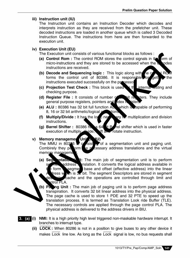
iii) Instruction unit (IU) The Instruction unit contains an Instruction Decoder which decodes and
interprets instruction as they are received from the prefetcher unit. These decoded instructions are loaded in another queue which is called 3 Decoded Instruction Queue. The instructions from here are then forwarded to the execution unit.
iv) Execution Unit (EU) The Execution unit consists of various functional blocks as follows :
(a) Control Rom : The control ROM stores the control signals in the form of micro-instructions and they are stored to be accessed when the decodes instructions are received.
(b) Decode and Sequencing logic : This logic along with the control ROM forms the control unit of 80386. It is responsible for getting the instructions executed successfully on the processor.
(c) Projection Test Check : This block is used for the internal testing and checking purpose.
(d) Register File : It consists of number of 32 bit registers. They include general purpose registers, pointers and index registers.
(e) ALU : 80386 has 32 bit full function ALU which is capable of performing 8, 16 or 32 bit arithmetic/logical operations.
(f) Multiply/Divide : It has the logic necessary for multiplication and division instructions.
(g) Barrel Shifter : 80386 has a 64 bit Barrel shifter which is used in faster execution of multiply, divide, shift and rotate instruction.
v) Memory management Unit (MMU) The MMU in 80386 is consisting of a segmentation unit and paging unit.
Combirely they perform the necessary address translations and the virtual memory management.
(a) Segmentation Unit: The main job of segmentation unit is to perform segment address translation. It converts the logical address available in the form of segment base and offset (effective address) into the linear Address which is 32 bit. The segment Descriptors are stored in segment descriptor cache and the operations are controlled through limit and control PLA.
(b) Paging Unit : The main job of paging unit is to perform page address transpiration. It converts 32 bit linear address into the physical address. The page cache is used to store 1 PDE and 32 PTE to speed up the translation process. It is termed as Translation Look ride Buffer (TLE). The necessary controls are applied through the page control PLA. The physical address is delivered to the address drivers in BIU.
(i) NMI: It is a high priority high level triggered non-maskable hardware interrupt. It
branches to interrupt type. (ii) LOCK : When 80286 is not in a position to give buses to any other device it
makes Lock line low. As long as the Lock signal is low, no bus requests shall
3. (a)
Vidyala
nkar

Vidyalankar : T.Y. Diploma AMP
1013/TY/Pre_Pap/Comp/AMP_Soln 142
be granted and 80286 shall remain in control of the buses. Lock situation is encountered during execution of lock prefix instructions during transition to Interrupt Service Routine (ISR) and during transitions of task switching.
(iii) HOLD: Whenever a device wants to request for the buses it is done by making HOLD line high. 80286 completes the current machine cycle and relinquishes the buses and indicates so to the bus requesting device by making HLDA signal high. Whenever buses are no more required by the requesting device it makes HOLD signal low. 80286 takes control of the buses and makes HLDA low.
MS – DOS : i) First operating system was developed by Microsoft for IBM PC compatible
systems. ii) Developed and Deployed in 1981, it is one of the oldest operating System
(OS) for Home/Personal computers. iii) MS – DOS is Texual mode command line interpxeter Driven operating
system. iv) MS DOS is not a highly modular or structured operating system. v) It performs the following fundamental or functions. (a) Hardware Control (b) Memory Management (c) Input and peripheral Resource Management (d) User Interface through (CLI) command line Interpreter. (e) OS utilities for managing Hardware components. (f) Disk and file Management. Structure of MS DOS Although not every structured OS, MS DOS provides a 4 layer structure.
User Interface Command line Interpreter
MS DOS utilities
Memory resident programs
DOS Device Drivers DOS function calls INT21H
BIOS Device Drivers BIOS function calls (INTOH – INT21H)
Hardware Resources
3. (b)
Vidyala
nkar

Prelim Question Paper Solution
1013/TY/Pre_Pap/Comp/AMP_Soln 143
i) Top layer of MS DOS consists of user Interface. It is Typically provided through
(a) Command line Interpreter (Through DOS file COMMAND.COM). (b) MS DOS utilities Different utilities for managing Hardware such as
FORMAT, FDISK, CHKDSK etc.
ii) Second layer of MS DOS consists of Memory Resident code (Through 2 Memory Resident files MSDOS.sys and IO.sys)- which performs basic kernel functions as
(a) Memory Management (b) Input output Hardware Resource Management iii) Third layer of MSDOS consists of MS DOS OS function calls. All the
MSDOS function calls are executed through interrupt 21H. Due to this fact, INT21H is called as DOS function called interrupt. Large number of OS calls are provided in interrupt 21H functions. The function no is typically specified in AH register.
These functions are used for performing following different operations : (a) Control IO : Character orienting functions operating on keyboard display
as console input and output. (b) Disk Drive functions : Performing various operations on floppy disk and
hard disk drives. (c) Date and Time functions : Processing system data and time. (d) Memory Management Functions : Processing memory allocation deal
location and management of virtual memory. (e) Process control function : Such as execute, terminate and stay resident
programs. (f) File input output functions : Such as open, close, read and write files.
iv) Miscellaneous DOS functions : This is the bottom layer of MS-DOS
programs. The BIOS consists of POST (Power on self Test) and BIOS function calls. The BIOS function call services are through following interrupts INT 5H print screen, INT 10H video services, INT 11H equipment determination, INT 12H memory sizing, INT 13H Disk services and INT 14H serial input output services, INT 15H miscellaneous services, INT 16H keyboard services, INT 17H Painter services, INT 19H Reboot the system and INT 1AH RTC services (Read time clock).
Vidyala
nkar

Vidyalankar : T.Y. Diploma AMP
1013/TY/Pre_Pap/Comp/AMP_Soln 144
Register Organisation of 80386 (Real Mode)
Interrupt Descriptor Table
Response to Interrupts in PVAM In protected mode, the X86 processors responds to the interrupts in a different way as compared to the same in Real mode. The sequence of steps of interrupt response in protected mode is as follows:
3. (c)
8 Byte IDT Entry
8 Byte IDT Entry
8 Byte IDT Entry
8 Byte IDT Entry
2
1
0 IDTR
IDT Base Address
IDT Limit
IDT Entries
255
Total size of IDT 256 × 8 = 2048 2KB
3. (d)
Vidyala
nkar

Prelim Question Paper Solution
1013/TY/Pre_Pap/Comp/AMP_Soln 145
Step 1: The Interrupt is decided to be serviced after the current instruction is completely executed.
Step 2: The E flags register is pushed on the top of the stack and stack pointer is decremented by 4. (for 80286 flag register is pushed and SP is decremented by 2)
Step 3: The IF and TF flags are then reset to stop any further recognition of interrupts as well as debug stops.
Step 4: The CS is pushed on top of the stack SP is decremented by 2, then EIP is pushed on top of the stack and SP is further is decremented by 4 (For 80286, IP is pushed and SP is decremented further by 2)
Step 5: The Interrupt vector value is captured (a) For Software interrupts it is in the instruction INT n itself. (b) For NMT, it is 2 (c) For INTR, it is received on D0 D7 from the device in the 2nd Interrupt
acknowledge cycle. Step 6: n is multiplied by 8 and referred to the Interrupt Descriptor table. It is
pointed by the Interrupt Descriptor table register (IDTR). Step 7: The IDT entry contains 8 bytes and it points to Interrupt gate, trap gate or
task gate descriptor. Step 8: The gate mechanism loads the necessary descriptor completes the
control transfer loading new (S and EIP values. (For 80286 IP). This starts the Interrupt service Routine (ISR).
U and V Pipelines Pentium is a superscalar processor and capable of executing 2 integer instruction simultaneously. It is carried out on 2 pipelines which are called as U and V pipeline U is a complete pipeline. It has its own address generation access to register files, a full function ALU and barrel shifter U pipeline can execute all the instructions in the instruction set of Pentium. The V pipeline is having address generation, registers access and ALU. V pipeline can execute only simple instructions. It cannot execute multiplication division etc. due to absence of barrel shifter. If the instructions are pairable 2 instructions are simultaneously executed over U and V pipelines. If they are not pairable only 1 instruction is executed and it is executed on U pipeline only. The register file contains all standard register such as general purpose registers. index registers and pointers. Both U and V ALU's are 32 bit and can perform ALU operations on 8, 16 and 32 Bit operands. Both the pipelines are connected to Data cache and can access it simultaneously. (i) Hardware interrupts and Software interrupt
Hardware interrupts Software interrupt 1) Interrupts caused by change in
the status on the Hardware interrupts pinie.
Software interrupts caused by the software interrupt instructions.
2) NMI, INTR INT n, INT 3, INT 0 3) They are triggered externally by
user. They are produced when certain conditions occur.
4) They are human controlled and hence could be avoided.
They are M/C generated and cannot be stopped.
3. (e)
4. (a) Vidyala
nkar

Vidyalankar : T.Y. Diploma AMP
1013/TY/Pre_Pap/Comp/AMP_Soln 146
(ii) Superscalar Execution
t1 t2 t3 t4 t5 t6 t7
I1 PFU D1U D2U EXU WBU U I2 PFV D1V D2V EXV WBV V I3 PFU D1U D2U EXU WBU U I4 PFV D1V D2V EXV WBV V I5 PFU D1U D2U EXV WBV U I6 PFV D1V D2V EXV WBV V
In Pentium processor, there are 2 integer pipelines. They are capable of executing instructions simultaneously as shown in the pipeline stage diagram for superscalar execution in Pentium, we can observe that at a time 2 instructions are being processes. When first 2 instructions I1 and I2 move on to decode 1 (D1), next 2 instructions I3 and I4 are prefetched simultaneously and when I1 and I2 move on to Decode 2 (D2), I3 and I4 get decoded in D1 simultaneously and at the same time I5 and I6 are fetched. If the instructions are pairable, they go down the U and V pipeline to get simultaneously executed. If the instructions are not pairable only 1 instruction is executed in U pipe and Pentium tries for subsequent instruction pairing. As the Pentium is capable of executing instructions simultaneously in more than one pipeline (U and V), if is called as the superscalar architecture processor. Such execution is called as superscalar exaction of instructions. Floating Point Pipeline of Pentium The Floating point pipeline of Pentium have 8 stages. The stages are : PF Prefetch D1 Decode stage 1 D2 Decode stage 2 EX Execute load operands X1 FP Execution stage 2 WF Write FP operands (Round/Normalize) ER Error Reporting
Pentium Superscalar
The 8 stages in Floating point pipeline can be explained as : 1) Prefetch (PF): In this stage, the operands are prefetched from the code
cache into the prefetch buffers. This stage is common with U and V integer pipelines.
2) Decode Stage 1 (D1) : This stage decodes the instruction performs instruction pairing check and branch predictions. This stage is also common with U and V integer pipelines.
3) Decode stage 2(D2) : In this stage, the floating point unit generates the control signals for execution. It also generates operand addresses.
4. (a)
Vidyala
nkar

Prelim Question Paper Solution
1013/TY/Pre_Pap/Comp/AMP_Soln 147
4) Execute (EX) : In this stage, FPU loads the data operands necessary for execution.
5) Execute stage 1(X1) : In this stage, FPU execution begins. For addition, subtraction Mantisa shifting is carried out. For multiplication and Derision, the mantisa is multiplied or divided. For Floating point data transfers, the transfers are executed.
6) Float point Execute stage 2 (X2) : For floating point mantisa addition and superscalar is carried out. For floating point multiple and dir exponent address and is carried out. For Data transfers, this stage is bypass.
7) WF (Write Floating Operands) : In this stage, the results are normalised. If necessary rounding off.
8) ER(Error Reporting) : In this stage, floating point errors and exceptions are reported as numerical errors.
(iii) Task Switching
In multitasking environment, task switching is necessary. The task switch is required to be undertaken due to i) New task comes in ii) Running task terminates and goes out iii) Running task is being task becomes ready. iv) Higher slice of currently running task expires. Task Switch
PF
D1
D2 D2 D2
EX
X1
X2
WF
ER
WB
EX
WB
EX
Outgoing Task Incoming Task
TS = 0 TS = 1 (CLTS)
T S S
T S S
TR
4. (a)
Vidyala
nkar

Vidyalankar : T.Y. Diploma AMP
1013/TY/Pre_Pap/Comp/AMP_Soln 148
Format of Task State Segment
In multitasking environment, task switching is required to be carried out by the OS. 80286 provides help for the task switching mechanism by implementing the task switch with the help of task register (TR). As the task switching is being carried out. Following sequence of events take place. i) The task register is pointing to the task state segment of currently
executing task. The context of this outgoing task is saved to its task state segment which includes an image of all processor registers. Simultaneously 80286 automatically sets TS bit = 1 at the beginning of this state.
ii) OS loads the task register selector either directly or indirectly through a task gate. TR descriptor also gets loaded subject to the protection checking. Now TR points to the tasked segment of incoming task.
iv) The context of incoming task is loaded from its taskted segment as the new context is loaded LDT, CS and IP also gets loaded. OS resets TS bit to 0.
v) As CS and IP of incoming task are loaded the task starts executing on 80286 processor.
During the process of task switching, no interrupts are recognised or serviced. Also LOCK remains low and buses are locked No DMA request would be entertained.
Task switching can be carried out directly by loading TR with the TSS descriptor of the incoming task. Such task switching is called as direct task switching. This type of task switching is used within the privilege level. The task switching can also be carried out indirectly by.
Pointing to a task gate descriptor which in turn loads TR with the TSS descriptor of the incoming task. Such task switching is called indirect task switching. Such task switching is done across the privilege level.
Format of TSS (Task state segment) Task state segment consists of a static set and a dynamic set. The static state is written by OS and never modified by the processor. The dynamic state consists of the processor register image and it is read as well as written by the processor.
Dynamic set
Static set
Vidyala
nkar

Prelim Question Paper Solution
1013/TY/Pre_Pap/Comp/AMP_Soln 149
(iv) Non System Segment Registers
CS Index TI RPL 32 bit
Segment limit 32 bit segment Base Address 9 Access Right Bits
SS Index TI RPL 32 bit
Segment limit 32 bit segment Base Address
DS Index TI RPL 32 bit
Segment limit 32 bit segment Base Address
ES Index TI RPL 32 bit
Segment limit 32 bit segment Base Address
FS Index TI RPL 32 bit
Segment limit 32 bit segment Base Address
GS Index TI RPL 32 bit
Segment limit 32 bit segment Base Address
System Segment Registers
DTR Index TI RPL 32 bit
Segment limit 32 bit segment Base Address
TR Index TI RPL 32 bit
Segment limit 32 bit segment Base Address
System Address Registers
GDTR 32 bit Base Address 16 Bit limit IDTR 32 bit Base Address 16 Bit limit
For of Non-System segment Descriptor
Segment Base Address (15 0)
Segment Limit (15 0)
Segment Base
Address (31-24)
G D O A V L
Segment Limit
(19-16) P DPL S E
C R A
Segment Base
Address (2316)
E D
W
Format of system Segment Descriptor
Segment Base Address (15 0)
Segment Limit (15 0)
Segment Base
Address (31-24)
G D O A V L
Segment Limit
(19-16) P
S=
O
Segment Base Address (2316) DPL TYPG
(i) Separate code and data cache Pentium has two separate 8 k byte caches for code and data as the
superscalar design and branch predication demand more bandwidth than a united cache.
The Pentium has introduced separate 8 k byte caches for code and data. From the fundamental principles of cache operation. To support the super scalar organization it required mode band with that
a united cache could not provide.
0 15 Descriptors
0 15 32 32 9
0 47
4. (a)
4. (b)
15 16 31
63 47 48
0
32
Vidyala
nkar

Vidyalankar : T.Y. Diploma AMP
1013/TY/Pre_Pap/Comp/AMP_Soln 150
Moreover to efficiently execute the branch predication, separate caches are more meaningful employed.
FloatingPoint pipeline The floatingpoint pipeline of Pentium consists of eight stages. They are prefetch, first, first decode second decode, operand fetch, first
execute, second execute, write float and error reporting. The eightstage pipeline in FPU allows a single cycle throughput. For
most of the basic floatingpoint instruction such a floating adds, subtract, multiply and compare.
The stages and their functions are given below. PF: Prefetch D1: Instruction decode D2: Address generation
Ex: Memory and register read, floating point data converted into memory format, memory write.
X1: Floating point execute, stage one memory data converted int floating point format, write operand to floating point register file.
X2: Floating point execute stage two. WF: Round floating point result and write to floating point register file bypass 2. ER: Error reporting, update status word.
(ii) Virtual Memory Management in 80386
Logical or Virtual Address
Selector Offset
Segment address
Linear address
Is PG = 1 in
CRO
Page Address Translation
Physical
15 0 31 0
N
Y
31 0
Segmentation (SU)
+ = MMU (Memory Management unit
(PU) Paging
4. (b) 4. (b) 4. (b)
Vidyala
nkar

Prelim Question Paper Solution
1013/TY/Pre_Pap/Comp/AMP_Soln 151
Page Address Translation in 80386
Format of PDE (Page Directory Entry)
Format of PTE (Page Table Entry)
Virtual Memory Management in 80386 80386 Provides virtual memory management in 2 stages. It is done through compulsory segmentation + optional paging. In segmentation, the logical or virtual address consisting of 16 bit segment selector and 32 bit offset is converted into 32 bit linear address by way of segment address translation. If the PG bit = 0, then this 32 bit linear address becomes 32 bit physical address. If the PG bit =1 (paging is enabled), then the linear address is translated into 32 bit physical address by way of page address translation. Combinely segmentation and paging carry out the complete virtual memory management. Segment unit and the paging unit are said to be part of the memory management unit (MMU).
PDBR
+ +
+
DIR INDEX
PAGE INDEX
OFSET
PDE PTE
1029 1023 4075
Physical
3 2 2 1 1 0
3 0 3 0 7 0 Page Directory
Page Directory
Page
Page Base AVL D A US
RW
P
12 N 1 9 8 7 6 5 4 3 2 1 0
Address Access
Page Base Table Address AVL A US
RW
P
12 N 10 9 8 7 6 5 4 3 2 1 0
Address Access
Vidyala
nkar

Vidyalankar : T.Y. Diploma AMP
1013/TY/Pre_Pap/Comp/AMP_Soln 152
Format of system segment Descriptor The diagram shows different types of descriptors supported by 80386. The system segment descriptors supported by 80386 are specified through the type field in the descriptor format. Types 0 7 are same as in 80286 they indicate 80286 compatible 16 bit protected mode operations. Types 8 F are there counterparts operated in 80386 compatible 32 bit protected mode. [Note : With the exception that the LDT and Task gate Descriptors are common to both 80286 and 80386] Segment Address Translation in 80386 PVAM
The Segment Address translation in 80386 protected mode is used to convert logical address into the Linear address. The logical address is provided in 2 components. It consists of 16 bit segment selector and 32 bit offset. The segment selector contains 2 bits requested privilege level, a table indicator bit and 13 bit of index. The selector is used to select 1 out of 16 K descriptors loaded to select 1 out of 16 K descriptors laded in the descriptor tables in physical memory (8 K in global description table + 8K in Local Descriptor Table). The selector point to specific 8 byte descriptor entry which contains segment base address segment limit and access layer. Subject to protection segments are loaded and 32 bit segment base address is added to 32 bit offset (subject to the limit checking) to generate a 32 bit linear address. Therefore the segment address translation translates logical or virtual address into the 32 bit linear address. It also provides the protection at segment level by privilege level checking, type checking and limit checking. The Virtual Memory Management and the operation is carried out in segmentation unit (SU) of 80386.
Segment Base Address
Logical Address
Segment Selector Offset 15 0 31 0
0 31
Linear address
8 Byte Descriptor Entry
Descriptor Table (LDI/GDT) LDTR/GDTR
5. (a)
Vidyala
nkar

Prelim Question Paper Solution
1013/TY/Pre_Pap/Comp/AMP_Soln 153
80386 has three control register structure of microprocessor 80386 a) CRO It is also known as the machine status word.
31 . . . . . . . . . . . . . 4 3 2 1 0 PG 0 0 0 0 0 0 0 0 0 0 0 0 0 R TS EM MP PE
PG (Paging Enable) : It is set to enable on chip paging unit. R (Reserved bit) : It is reserved by Intel
TS (Task Switched) : It is automatically set whenever a task switch operation is performed.
EM (Emulate Coprocessor) : It is set when coprocessor S/W is present. MP (Monitor Processor) : It is set when coprocessor 80387 is present. PE (Protection Enable) : It is set when 80386 enters into protected mode.
b) CR1 It is reserved for use in future Intel processors.
c) CR2 It holds 32-bit linear address that caused last page fault defected.
31 0 Page Fault Linear Address Register
d) CR3 It contains the physical base address of the page directory table.
31 12 11 0
Page Directory Base Add r 0 0 0 0 0 0 0 0 0 0 0 0 The 8 stages in Floating point pipeline can be explained as : i) Prefetch (PF): In this stage, the operands are prefetched from the code
cache into the prefetch buffers. This stage is common with U and V integer pipelines.
ii) Decode Stage 1 (D1) : This stage decodes the instruction performs instruction pairing check and branch predictions. This stage is also common with U and V integer pipelines.
iii) Decode stage 2(D2) : In this stage, the floating point unit generates the control signals for execution. It also generates operand addresses.
iv) Execute (EX) : In this stage, FPU loads the data operands necessary for execution.
v) Execute stage 1(X1) : In this stage, FPU execution begins. For addition, subtraction Mantisa shifting is carried out. For multiplication and Derision, the mantisa is multiplied or divided. For Floating point data transfers, the transfers are executed.
vi) Float point Execute stage 2 (X2) : For floating point mantisa addition and superscalar is carried out. For floating point multiple and dir exponent address and is carried out. For Data transfers, this stage is bypass.
vii) WF (Write Floating Operands) : In this stage, the results are normalised. If necessary rounding off.
viii) ER(Error Reporting) : In this stage, floating point errors and exceptions are reported as numerical errors.
5. (b)
5. (c)
Vidyala
nkar

Vidyalankar : T.Y. Diploma AMP
1013/TY/Pre_Pap/Comp/AMP_Soln 154
Pipeline in 80286 80286 has a 3 staged pipeline which consists of i) Fetch : In fetch stage, the instructions are fetches by the prefetcher and
loaded into the 6 byte prefetch queue.
ii) Decode : In this stage, the instructions are taken from the 6 byte prefetched queue. They are decoded and they are loaded into the 3 Decoded instruction Queue.
iii) Execute : In this stage, instructions are takes from the 3 decoded instruction queue one by one and they are executed. DVC to the 3 staged pipeline, 80286 allows the instructions to the executed faster and the performance of 80286 processor is higher due to this 3 staged pipeline.
Types of Descriptors
Format of System Segment Descriptor
Segment Address Translation in Protected mode of 80286 struts with the supply of logical address specified in 2 components. A 16 bit segment selector value and a 16 bit offset. The 16 bit segment selector consists of a 13 bit index. It is multiplied by 8 and the generated value is added to the 24 bit base address
6. (a)
Types of Descriptors
Conventional Segment System Segment Descriptors Non-System Segment
Descriptors
Code (CS)
Stack (SS)
Data (DS, ES)
LDT Descriptor
(LDTR)
Task state Segment (TSS) Descriptor(TR)
Gate Descriptors
E = 0
ED = 0 ED = 1 E = 0 E = 1
(2) (1, 3)
S = 1 S = 0
Call gate (4) Interrupt (6)
Gate Trap gate (7) Task gate (5)
Segment Base Address (15 0)
Segment Limit (15 0)
Not Used Segment base
Address (2316)
P DPL O TYPE A
31 16 15 0
63 32 48 47
8 bit Access Layer
+4
0
Descriptor Privilege Level
6. (b)
Vidyala
nkar

Prelim Question Paper Solution
1013/TY/Pre_Pap/Comp/AMP_Soln 155
provided by either the Local Descriptor Table Register (LDTR) or Global Descriptor Table Register (GDTR). The TI bit (Table Indicator) specify the descriptor table to be used. It TI bit is 0 GDTR is used. If TI bit is 1, LDTR is used. LDTR accesses Global Descriptor Table (LDT) and GDTR access Global Descriptor Table (GDT) is the memory of system. These 2 descriptor tables contain descriptor entries. The Global Descriptor Table (GDT) is global and common to all the renouncing applications whereas local Descriptor Table is private and separate for each running application. Both these tables can contain a maximum of 8K descriptor entries. Each Descriptor entry is of 8 bytes. The index value from the selector effectively selects LDT and GDT and that descriptor entry is checked for the protection. It the protection check passes, the selectors and descriptor of the respective segment register are loaded. The segment is now available for use and the physical address will be generated by adding 16 bit offset to the 24 bit segment base address subject to the limit checking. The physical address generated is of 24 bit. In this way segment address translation is performed to generate 24 bit physical address given the logical address.
Segment Address Translation in 80286 PVAM Memory map of 80286
IVT
1 MB
Real mode
Rese
16 MB PVAM FFFFFH
FFFFOH
003FFH 0000OH
6. (c)
Vidyala
nkar

Vidyalankar : T.Y. Diploma AMP
1013/TY/Pre_Pap/Comp/AMP_Soln 156
The memory map of 80286 is of 16 MB. The highest address location is FFFFFFH. However in Real mode as the address translation generates only 20 bit addresses being compatible to 8086, the memory that is accessible in the Real mode is only 1 MB. In Protected mode, full 24 bit segment base address is provided and therefore it is possible to generate full 24 bit addresses. As a result of this softwares operating in protected mode of 80286 are able to take advantage of access to complete 16 MB memory address space.
Page Address Translation in 80386 The diagram shows paging mechanism in 80386. Paging is done through 2 level paging mechanisms. The 32 bit linear address is differentiated into 3 logical components. Least significant 12 bits are called offset. Middle 10 bit bits are called table index and most significant 10 bits are called Directory index. The Directory index is used to select 1 page directory entry out of possible 1024 entries stored in a page directory. The page directory is situated in the memory and its base address is given by page Directory Base Register (PDBR) which is contained in CR3. The selected page directory entry contains base address of the page table and the page table may be there in the physical memory or may not be there. If page table is not there in the physical memory, 80386 generates page fault (INT 14). The virtual memory manages handles the page fault. It accesses the address which created page fault in CR2. (Page Fault linear
Logical Address
Segment selector Offset +
Physical Address
24 Bit S.B.A
8 Bit A. L
16 Bit S.L
15 0 15 0
47 0
28 0 16 24
24
T I RPL Index
15 0
Protection Check
+
16 48
24
24
24 Bit SRA
''
23 0
TI = 1
TI = 0
LDTR
GDTR
8 Byte Descriptor
Entry
LDT or GDT in
the physical memory
Seg. limit seg. Base
Access Layer
Selector Descriptor
6. (d) Vidyala
nkar

Prelim Question Paper Solution
1013/TY/Pre_Pap/Comp/AMP_Soln 157
Address Register) brings the necessary page in physical memory and makes corresponding P bit 1. The table index is used to select 1 page table entry out of possible 1024 entries in the page table. The page table entry (PTE) contains page base address. The required page may or may not be there in the physical memory. Similar page fault mechanism is used and once the page is available in physical memory 121 bit offset is used to access the information at the physical address. In 80386, page directory page table and page are all of 4 KB in size. They are also aligned 4kB. The memory is viewed as containing 4 KB pages. Such 1024 pages access through a page table accessing total 4MB memory and such 1024 pages tables pointed through a page directory accessing a total of 4GB memory. Therefore linear address maps onto 4GB of physical space and this linear address can be generated form 1 out of given 16 K descriptors at the segment level. Therefore the total virtual address space of 80386 is 16 K descriptors each on of which generating a 32 bit linear address that maps onto 4GB physical space. Therefore 16K 4GB = 64TB. 80386 supports total of 64 of virtual address space. Branch Predictions in Pentium Back 20000008 :
2000037 : INZ Back
Branch Target Buffer (BTB)
Source Address Target Address State Bit 20000037 20000008 ST
Branch
No Branch
6. (e)
Vidyala
nkar

Vidyalankar : T.Y. Diploma AMP
1013/TY/Pre_Pap/Comp/AMP_Soln 158
Branch prediction logic of Pentium logic of Pentium operates with a special cache of branch addresses that keeps track of 64 most recently taken branches. The branch table that keeps this information is called as Branch Target Buffer (BTB). It stores the source address (the address at which branch instruction appears). Target address (the address to which the branch would take place) and the branch history state bits. The branches are predated to be taken or not taken in D1 stage of pipeline. If the current state is ST (strongly taken) or WT (Weakly Taken), the branch is predicted to be taken. If the current state is WNT (Weakly Not Taken) or SNT (Strongly Not Taken) the branch is predicted not to be taken. If the branch is predicted not to be taken, prefetching continues in the same buffer source address onwards. If the branch is predicted to be taken the perfected buffer is switched and prefetching is done on target address onwards. In the execution stage (Ex), the branch is actually and if the branch is actually not taken, the state bits are downgraded. If the prediction is correct, pipeline runs smoothly. If the prediction is wrong, U pipeline incurs 3 clocks and V pipeline insures 4 clocks penalty. Branch predication logic enhances the performance of Pentium as it minimizes the pipeline problem.
ST WT WNT SNT
Downgrade if Branch is Not taken (Ex)
Upgrade if Branch is taken (Ex)
(D1) Predict Branch Predict no branch (D1)
Vidyala
nkar