txs25-4 evaluation kit user guide
TRANSCRIPT

1
®
User’s Guide: TXS25-4 Evaluation KitAN1435.0Application Note February 25, 2009
Complete Amplifier Evaluation System• TXS25-4: 4-Channel Digital Amplifier
• Single Power Supply (+25V) Operation
• Internally Generated Negative Rail High-voltage Supply (-25V)
• Internally Generated and Regulated Low-voltage Supplies (+5V/+3.3V/1.8V)
• D2Audio Canvas II™ Installation CD-ROM (includes USB Driver and D2Audio Canvas II User’s Guide)
• Detachable Digital/Analog Audio/Control I/O and Power Assembly Boards
• “SCAMP III” Header Pins on Digital/Analog Audio/Control I/O Board Enables In-system Firmware Upgradeability
• Optical (TOSLINK) and Coax Digital S/PDIF Inputs that Accept an IEC60958 Compliant Interconnect Carrying Linear PCM with an Fs of 32kHz~192kHz
• Optical (TOSLINK) Digital S/PDIF Output
• 4 Channels of Analog Audio Inputs Using High-Performance 4-Channel Analog-to-Digital Converter (ADC)
• 2 I2S/Left-Justified Digital Audio Input Headers
• 2 I2S/Left-Justified Digital Audio Output Headers
• Rotary Knob Connected to GPIO Lines Enables Simple Master Volume Control for Channels 1 and 2
• Subwoofer Analog Audio Output (Passive Filtered PWM Line Level Output)
• High-Quality Speaker Banana-Jack Connectors
D2Audio Canvas II™GUI Simplifies System Design• Intuitive, “Point-and-click” Audio-Centric User Interface
Simplifies Evaluation of All Audio Processing Configurations
• Configuration for Stereo, Dual Zone, Stereo Bi-Amp or Powered 2.1 Systems Takes Less than a Minute
Selectable DSP Processing Functions• Input Selection (Analog, S/PDIF, I2S/Left-Justified)
• 4 Independent Channels of Audio Processing- Tone Control- Matrix Mixing- Programmable Crossover with Butterworth,
Linkwitz/Riley, Bessel Filter Types- 5-Band and 3-Band Parametric EQ- Master Volume Control- Loudness Contour- Individual Channel Time Delay- Per Channel Dynamic Range Compression/Limiting- Independent Channel Level Controls - Enables
Independent Level Control for Amplified Channels 1, 2, 3 and 4 Outputs as well as Digital Audio Outputs
D2Audio SoundSuite™ Immersive Processing• Mono2Stereo™
• WideSound™
• DeepBass™
• AudioAlign™
The TXS25-4 Evaluation Kit is a complete amplifier evaluation system for the TXS25-4 digital amplifier module. Audio system designers can quickly evaluate all of the features and functions of the TXS25-4 design with this system.
This system offers the ultimate in configurations, digital/analog I/O and power supply connection. It offers headers for all digital audio inputs and outputs so that the system designer can quickly and easily “wire-wrap” into the board. This enables any I2S/Left-Justified digital audio source to be delivered from any digital audio source such as an HDMI™ receiver or a Media Networking Processor and input into the TXS25-4 amplifier with minimum effort. A header is also offered for the control communication bus (2-wire interface), which enables fast connection of a system microcontroller for rapid prototyping.
The D2Audio Canvas GUI software simplifies system design with an intuitive, audio-centric user interface with “point-and-click” options on a Windows™ PC. Organized processing blocks are included for audio input selection, Tone Control, Crossovers, Parametric Equalizers, Adjustable Time Delay, Signal Limiter/Compressor, Volume Control, Loudness Contour, and Independent Level Control.
CAUTION: These devices are sensitive to electrostatic discharge; follow proper IC Handling Procedures.1-888-INTERSIL or 1-888-468-3774 | Intersil (and design) is a registered trademark of Intersil Americas Inc.
Copyright Intersil Americas Inc. 2009. All Rights ReservedAll other trademarks mentioned are the property of their respective owners.

Application Note 1435
TXS25-4 Evaluation Kit• Complete Evaluation Platform for TXS25-4
• 4 Channels of Amplified Speaker Outputs
• 4 Channels of Analog Inputs
• 4 Channels of Digital Audio Inputs(1 S/PDIF and 2 x I2S/Left-Justified Inputs)
• 4 Channels of Digital Audio Inputs (1 S/PDIF and 2 x I2S/Left-Justified Outputs)
• All necessary voltages are generated from single +25V power source reducing cost and complexity of the system power supply
• Internally Regulated Low-voltage supplies (+5V/+3.3V/1.8V)
• Master Volume Knob (Channels 1 and 2)
2 AN1435.0February 25, 2009

Application Note 1435
Getting Started
OverviewThe TXS25-4 Amplifier evaluation kit consists of 3 boards. These boards, shown in Figure 1, consist of the main amplifier board, an input board, and an output board. Each of these 3 boards are shown in detail in Figures 2, 3, and 4. Ribbon cables (supplied) interconnect the 3 boards.
The system can be configured either through software (refer also to D2Audio Canvas II Software Configuration Documentation found on the D2Audio Canvas II Software CD) or configured by hardware settings (see “Input Source Options” on page 17).
Platform ConfigurationsThe TXS25-4 Amplifier kit may be configured as a stereo amplifier with a single or multiple inputs, and is also capable of providing a summed and low-pass filtered output which can then be sent to an external powered subwoofer. The flexible signal processing flow and extensive digital audio inputs and outputs of the TXS25-4 also allows for processed output to be connected (as on this evaluation platform) to an external DAC to enable post-processed Line-Level Outputs or Headphone Outputs.
WARNINGThis symbol is used to warn operators that uninsulated “dangerous voltages” are present within this equipment that may impose risk of electrical shock
FIGURE 1. TSX25-4 AMPLIFIER BOARDS
3 AN1435.0February 25, 2009

Application Note 1435
FIGURE 2. DIGITAL/ANALOG AUDIO/CONTROL I/O BOARD - TOP VIEW
4 AN1435.0February 25, 2009

Application Note 1435
FIGURE 3. TXS25-4 AMPLIFIER BOARD - TOP VIEW
5 AN1435.0February 25, 2009

Application Note 1435
FIGURE 4. AMPLIFIER OUTPUT BOARD - TOP VIEW
6 AN1435.0February 25, 2009

Application Note 1435
Connection Diagram
D2-814xx IC
CHANNEL 4OUT
CHANNEL 1OUT
RESETS/PDIF
OPTICAL INUSB
MC
LKT
SC
LKT
LRC
KT
SD
OU
T0S
DO
UT1
COAX S/PDIFStatus LED
OPTICAL S/PDIFStatus LED
STATUS LEDs:Load CompleteLoad ActiveI2C ActiveUSB Active
+
-
COAX
OPT
SCLK
0LR
CK0
SDIN
0
S/PDIFOPTICAL OUT
MASTERVOLUME
ERRORLED
CHANNEL 3 PWM SUBWOOFER
OUT
AUDIOIN1
AUDIOIN2
S/PDIF COAX IN
Amplifier Output Board
+25V+25VG
ND
GN
D
J2
J5
+
-
+
-
CHANNEL 2OUT
CHANNEL 3OUT
+
-
1357911131517192123252729
24681012141618202224262830
AUDIOIN3
AUDIOIN4
123456789101112
SCLK
1LR
CK1
SDIN
1
J8
J7
1357911131517192123252729
24681012141618202224262830
123456789101112
J6
nRE
SET
BO
OT_E
EnE
RR
OR
GP
IO0
GP
IO1
PS
SYN
C
J4
+5V+3.3V
+1.8G
ND
J19
J27
J28
Digital/Analog Audio/Control I/O Board
TXS25-4 Amplifier Board
J3
J9
US
B
AIN
1
AIN2
AIN
3
AIN
4
Sub O
ut
S/P
DIF
CO
AX
INS
/PD
IFO
PTIN
S/PDIF
CO
AXO
UT
J28: +25 VDCPower Supply
Connection
FIGURE 5. TXS25-4 AMPLIFIER PLATFORM CONNECTION AND JUMPER DIAGRAM
7 AN1435.0February 25, 2009
Application Note 1435
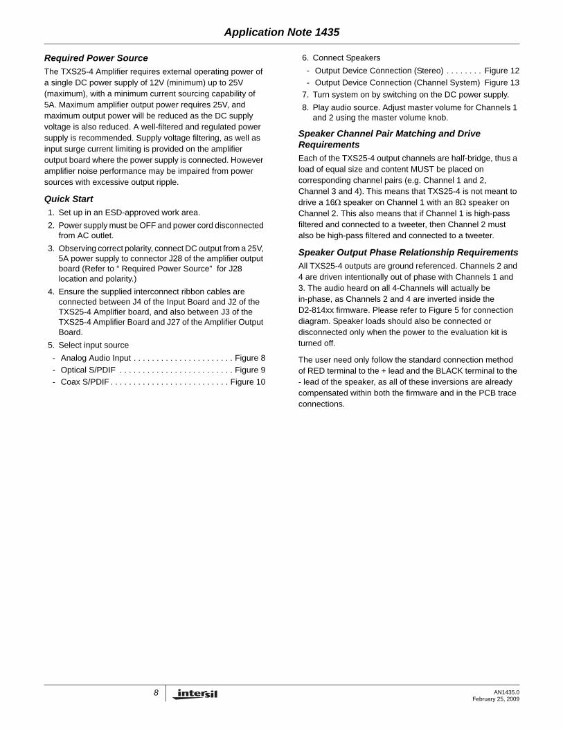
Required Power SourceThe TXS25-4 Amplifier requires external operating power of a single DC power supply of 12V (minimum) up to 25V (maximum), with a minimum current sourcing capability of 5A. Maximum amplifier output power requires 25V, and maximum output power will be reduced as the DC supply voltage is also reduced. A well-filtered and regulated power supply is recommended. Supply voltage filtering, as well as input surge current limiting is provided on the amplifier output board where the power supply is connected. However amplifier noise performance may be impaired from power sources with excessive output ripple.
Quick Start1. Set up in an ESD-approved work area.2. Power supply must be OFF and power cord disconnected
from AC outlet.3. Observing correct polarity, connect DC output from a 25V,
5A power supply to connector J28 of the amplifier output board (Refer to “ Required Power Source” for J28 location and polarity.)
4. Ensure the supplied interconnect ribbon cables are connected between J4 of the Input Board and J2 of the TXS25-4 Amplifier board, and also between J3 of the TXS25-4 Amplifier Board and J27 of the Amplifier Output Board.
5. Select input source- Analog Audio Input . . . . . . . . . . . . . . . . . . . . . . Figure 8- Optical S/PDIF . . . . . . . . . . . . . . . . . . . . . . . . . Figure 9- Coax S/PDIF . . . . . . . . . . . . . . . . . . . . . . . . . . Figure 10
6. Connect Speakers- Output Device Connection (Stereo) . . . . . . . . Figure 12- Output Device Connection (Channel System) Figure 13
7. Turn system on by switching on the DC power supply.8. Play audio source. Adjust master volume for Channels 1
and 2 using the master volume knob.
Speaker Channel Pair Matching and Drive RequirementsEach of the TXS25-4 output channels are half-bridge, thus a load of equal size and content MUST be placed on corresponding channel pairs (e.g. Channel 1 and 2, Channel 3 and 4). This means that TXS25-4 is not meant to drive a 16Ω speaker on Channel 1 with an 8Ω speaker on Channel 2. This also means that if Channel 1 is high-pass filtered and connected to a tweeter, then Channel 2 must also be high-pass filtered and connected to a tweeter.
Speaker Output Phase Relationship RequirementsAll TXS25-4 outputs are ground referenced. Channels 2 and 4 are driven intentionally out of phase with Channels 1 and 3. The audio heard on all 4-Channels will actually be in-phase, as Channels 2 and 4 are inverted inside the D2-814xx firmware. Please refer to Figure 5 for connection diagram. Speaker loads should also be connected or disconnected only when the power to the evaluation kit is turned off.
The user need only follow the standard connection method of RED terminal to the + lead and the BLACK terminal to the - lead of the speaker, as all of these inversions are already compensated within both the firmware and in the PCB trace connections.
8 AN1435.0February 25, 2009

Application Note 1435
Required SpeakerConnectionsTXS25-4 Amplifier Module
Channel 1+-
+-
Channel 3
-+ Channel 4
Channel 2-+
Note: Channels 2, 4 are 180 degrees out of phase vs. Channels 1, 3.The above speaker connections are necessary to have all channels in phase.
Speaker Out 1+: J3/1
Speaker Out 3+: J3/9
Speaker Out 2-: J3/4
Speaker Out 4-: J3/12
FIGURE 6. REQUIRED LOUDSPEAKER CONNECTIONS
9 AN1435.0February 25, 2009

10A
N1435.0
February 25, 2009
2Speaker 1 PWM Output (+/-)
SDOUT0 (Left Subframe)
Speaker 2 PWM Output (+/-)
SDOUT0 (Right Subframe)
Speaker 3 PWM Output (+/-)
Speaker 4 PWM Output (+/-)
SDOUT1 (Left Subframe)
SDOUT1 (Right Subframe)
2
2
2
3-Band Parametric EQ
3-Band Parametric EQ
Application N
ote 1435
MatrixMixer
SPDIFRX
SDIN0
SDIN1
D2Audio SoundSuite
Mono2Stereo WideSound DeepBass AudioAlignINPUT
SELECT
CompressorLoudness
MasterVolume
Channel Attenuation
CompressorLoudness Channel Attenuation
CompressorLoudness Channel Attenuation
CompressorLoudness Channel Attenuation
CompressorLoudness Channel Attenuation
Channel Attenuation
Channel Attenuation
Channel Attenuation
Time DelayLP Filter
Time DelayLP Filter
Time DelayLP Filter
Time DelayLP Filter
Time DelayLP Filter
HP Filter
HP Filter
HP Filter
HP Filter
5-Band Parametric EQ
Tone Control
Tone Control
Tone Control
5-Band Parametric EQ
Router
StereoRouter
FIGURE 7. TXS25-4 SIGNAL FLOW DIAGRAM

Application Note 1435
DAE-1D2-814xx IC
MC
LKTS
CLK
TLR
CKT
SD
OU
T0S
DO
UT1
COAX
OPT
SCLK0
LRC
K0
SDIN
0
MASTERVOLUME
Amplifier Output Board
+25V+25VG
ND
GN
D
J2
J5
+
-+
-
1357911131517192123252729
24681012141618202224262830
123456789101112
SCLK1
LRC
K1
SDIN
1
J8
J7
1357911131517192123252729
24681012141618202224262830
123456789101112
J6nR
ESET
BOO
T_EEnER
RO
RG
PIO0
GPIO
1PSSYN
C
J4
+5V+3.3V
+1.8G
ND
J19
J27
J28
Digital/Analog Audio/Control I/O Board
TXS25-4 Amplifier Board
J3
J9
AnalogInputs
L R L R
Sub O
ut
AIN
1
AIN
2
AIN
3
AIN
4
S/PD
IFC
OA
XIN
S/PD
IFO
PTIN
S/P
DIF
OP
TO
UT
US
B
+
-+
-
FIGURE 8. STEP 5: ANALOG INPUT
11 AN1435.0February 25, 2009

Application Note 1435
MC
LKT
SC
LKT
LRC
KT
SD
OU
T0S
DO
UT1
COAX
OPT
SC
LK0
LRC
K0
SD
IN0
+25V+25VG
ND
GN
D
J2
J5
+
-+
-
1357911131517192123252729
24681012141618202224262830
123456789101112
SC
LK1
LRC
K1
SD
IN1
J8
J7
1357911131517192123252729
24681012141618202224262830
123456789101112
J6
nRE
SE
TB
OO
T_E
EnE
RR
OR
GP
IO0
GP
IO1
PS
SY
NC
J4
+5V+3.3V
+1.8G
ND
J19
J27
J28
J3
J9OPTICAL S/PDIF
Status LED
S/PDIFOptical Input
COAX
OPTICAL
OPTICAL S/PDIF INPUTJUMPER
DAE-1D2-814xx IC
MASTERVOLUME
Amplifier Output Board
Digital/Analog Audio/Control I/O Board
TXS25-4 Amplifier Board
Sub Out
AIN1
AIN2
AIN3
AIN4
S/PD
IFC
OAX
IN
S/PD
IFO
PTIN
S/PD
IFO
PT
OU
T
USB
+
-+
-
FIGURE 9. STEP 5: OPTICAL (TOSLINK) S/PDIF INPUT
12 AN1435.0February 25, 2009

Application Note 1435
MC
LKTSC
LKTLR
CK
TSD
OU
T0SD
OU
T1
COAX
OPT
SCLK0
LRC
K0
SDIN
0+25V+25VG
ND
GN
D
J2
J5
+
-+
-
1357911131517192123252729
24681012141618202224262830
123456789101112
SCLK1
LRC
K1
SDIN
1
J8
J7
1357911131517192123252729
24681012141618202224262830
123456789101112
J6
nRE
SET
BOO
T_EE
nER
RO
RG
PIO
0G
PIO
1PS
SYN
C
J4
+5V+3.3V
+1.8G
ND
J19
J27
J28
J3
J9
COAX S/PDIFStatus LED
S/PDIFCOAX Input
COAX
OPTICAL
COAX S/PDIF INPUTJUMPER
DAE-1D2-814xx IC
MASTERVOLUME
Amplifier Output Board
Digital/Analog Audio/Control I/O Board
TXS25-4 Amplifier Board
Sub Out
AIN1
AIN2
AIN3
AIN4
S/PDIFCO
AXIN
S/PDIF
OPTIN
S/PDIFO
PTO
UT
USB
+
-+
-
FIGURE 10. STEP 5: COAXIAL S/PDIF INPUT
13 AN1435.0February 25, 2009

Application Note 1435
MC
LKTS
CLKT
LRC
KTS
DO
UT0
SD
OU
T1
COAX
OPT
SCLK0
LRC
K0
SDIN
0+25V+25VG
ND
GN
D
J2
J5
+
-+
-
1357911131517192123252729
24681012141618202224262830
123456789101112
SCLK1
LRC
K1
SDIN
1
J8
J7
1357911131517192123252729
24681012141618202224262830
123456789101112
J6
nRE
SETBO
OT_EE
nERR
OR
GPIO
0G
PIO1
PSSY
NC
J4
+5V+3.3V
+1.8G
ND
J19
J27
J28
J3
J9
CHANNEL 3 OUT(Left)
CHANNEL 4 OUT(Right)
CHANNEL 1 OUT(Left)
CHANNEL 2 OUT(Right)
Subwoofers Tweeters
DAE-1D2-814xx IC
MASTERVOLUME
Amplifier Output Board
Digital/Analog Audio/Control I/O Board
TXS25-4 Amplifier Board
Sub O
ut
AIN1
AIN2
AIN3
AIN4
S/PDIF
CO
AXIN
S/PDIF
OP
TIN
S/PDIF
OP
TO
UT
US
B
+
-+
-
FIGURE 11. STEP 6: OUTPUT DEVICE CONNECTION FOR A STEREO/BI-AMP SYSTEM
14 AN1435.0February 25, 2009

Application Note 1435
MC
LKT
SC
LKT
LRC
KT
SD
OU
T0
SD
OU
T1
+
-
COAX
OPT
SCLK0
LRC
K0
SDIN
0+25V+25VG
ND
GN
D
J2
J5
+
-+
-
+
-
1357911131517192123252729
24681012141618202224262830
123456789101112
SCLK1
LRC
K1
SDIN
1
J8
J7
1357911131517192123252729
24681012141618202224262830
123456789101112
J6
nRE
SE
TB
OO
T_E
EnER
RO
RG
PIO
0G
PIO
1P
SS
YN
C
J4
+5V+3.3V
+1.8G
ND
J19
J27
J28
J3
J9
CHANNEL 3 OUT(Left)
CHANNEL 4 OUT(Right)
CHANNEL 1 OUT(Left)
CHANNEL 2 OUT(Right)
Subwoofer
Full-RangeSpeakersBridge-
TiedLoad
DAE-1D2-814xx IC
MASTERVOLUME
Amplifier Output Board
Digital/Analog Audio/Control I/O Board
TXS25-4 Amplifier Board
Sub O
ut
AIN1
AIN2
AIN3
AIN4
S/PDIF
CO
AXIN
S/PD
IFO
PTIN
S/PD
IFO
PTO
UT
USB
FIGURE 12. STEP 6: OUTPUT DEVICE CONNECTION FOR A 2.1 CHANNEL SYSTEM
15 AN1435.0February 25, 2009

Application Note 1435
MC
LKT
SC
LKT
LRC
KT
SD
OU
T0S
DO
UT1
COAX
OPT
SCLK
0LR
CK
0SD
IN0
+25V+25VG
ND
GN
DJ2
J5
+
-+
-
1357911131517192123252729
24681012141618202224262830
123456789101112
SCLK
1LR
CK
1SD
IN1
J8
J7
1357911131517192123252729
24681012141618202224262830
123456789101112
J6
nRE
SE
TB
OO
T_EE
nER
RO
RG
PIO
0G
PIO
1P
SSY
NC
J4
+5V+3.3V
+1.8G
ND
J19
J27
J28
J3
J9
CHANNEL 4 OUT(Center)
CHANNEL 1 OUT(Left)
CHANNEL 2 OUT(Right)
Full-RangeSpeakers
PoweredSubwoofer
CHANNEL 3 PWMLINE-LEVEL
SUBWOOFEROUT
+
-+
-
DAE-1D2-814xx IC
MASTERVOLUME
Amplifier Output Board
Digital/Analog Audio/Control I/O Board
TXS25-4 Amplifier Board
Sub Out
AIN
1
AIN
2
AIN
3
AIN
4
S/P
DIF
CO
AX
IN
S/P
DIF
OPTIN
S/PD
IFO
PT
OU
T
USB
Full-RangeSpeaker
FIGURE 13. STEP 6: OUTPUT DEVICE CONNECTION FOR A 3.1 CHANNEL SYSTEM
16 AN1435.0February 25, 2009

Application Note 1435
Input Source OptionsThe TXS25-4 amplifier design contains 4 audio input channels. Several audio input source connections are available on the evaluation kit for these inputs.
Selecting an Audio Input Type (S/PDIF, I2S/LJ or Analog)The default (which includes after a reset or power cycle) settings for the TXS25-4 firmware select the S/PDIF input. The selection of the audio input can only be changed using the Input Select Window inside the D2Audio Canvas II user interface GUI.
Selecting Between I2S/Left-Justified Header Input and Analog InputIn order to use the Analog Inputs, the user must select the “I2S” input. Additionally they must make sure that J18 is jumpered. By jumpering both the top and bottom J18 jumpers, both I2S streams from the 4 Channel ADC are sent to both the SAI0 input (labeled I2S0 on the board) and the SAI1 input (labeled I2S1 on the board). In order to use the I2S/Left-Justified input headers for both SAI0 and SAI1 input, the user must select the same “I2S” input in the D2Audio Canvas II menu in addition to making sure that J18 is NOT jumpered. Figure 14 shows how the board needs to be configured to route both I2S streams from the 4-Channel ADC to both the SAI0 input (labeled I2S0 on the board) and the SAI1 input (labeled I2S1 on the board). If the user wants to send I2S or Left-Justified data into the SAI0 or SAI1 input ports, they are free to “wire-wrap” into the input headers located at J5 and J8. If they choose to do this, they must remove both jumpers from J18.
Selecting Between Coaxial and Optical S/PDIF InputJ19 can be jumpered between Coax and Opt during operation with out a need for a board reset in order to select Coaxial or Optical S/PDIF input. Figure 15 shows how to
select the Optical S/PDIF input. The user must still select the S/PDIF input mode.
When the S/PDIF input mode is selected (SPDIFRX), the COAX/OPT jumper (J19) determines which S/PDIF interface will be used.
Default ConfigurationTable 3 highlights the SPDIF I/O board jumper configuration for the default factory setting for the TXS25-4 evaluation platform. NOTE: The jumpers are stored on the ground pins for this configuration. If N/A is listed in the Default Jumper Setting column then a jumper is not provided nor should the associated header ever be shorted.
TABLE 1. EVALUATION KIT SOURCE OPTIONS
INPUT CHANNEL
AVAILABLE DIGITAL SOURCE
CONNECTIONS ON EVALUATION KIT
AVAILABLE ANALOG SOURCE
CONNECTIONS ON EVALUATION KIT
Channels 1 thru 4 Coax S/PDIF receiverOptical S/PDIF receiver I2S/Left-Justified input headers
Direct connection to 4 Channel ADC, which is connected to the I2S/Left-Justified
EN ADC TO I2S0J18
EN ADC TO I2S1
FIGURE 14. ROUTING I2S DATA FROM THE 4-CHANNEL ADC TO THE SAI0 AND SAI1 INPUTS
TABLE 2. J13 - S/PDIF INPUT SELECTION OPTIONS
S/PDIF INPUT SELECTION COAX OPT
COAX/OPT When S/PDIF input mode is enabled the Coax S/PDIF connector is selected
When S/PDIF input mode is enabled the Optical S/PDIF connector is selected
NOTE: These jumpers are not only read at power-up and after a reset to the amplifier design, but also during run time. Changes to the jumpers at any time will cause the settings to have an immediate effect and do not require a reset of the amplifier design to take effect.
FIGURE 15. SELECTING BETWEEN COAXIAL AND OPTICAL S/PDIF INPUT
17 AN1435.0February 25, 2009

Application Note 1435
.
Master Volume ControlEach time the board is reset or powered up, the master volume will revert back to the default setting as stored in the EEPROM within the amplifier design. These settings can be saved to different levels by using D2Audio Canvas II software with the “Save Settings to EEPROM” command. When shipped from the factory, these value are -20dB. While the board is powered up, the master volume for only Channels 1 and 2 may be adjusted by turning the Master Volume Control knob located on the input board. Adjusting the Master Volume knob will adjust the Master Volume slider inside the D2Audio Canvas II GUI, provided that polling has been enabled within the D2Audio Canvas II program.
TABLE 3. DEFAULT DIGITAL/ANALOG AUDIO/CONTROL I/O BOARD FACTORY JUMPER SELECTION
JUMPER NUMBER DESCRIPTIONDEFAULT JUMPER
SETTINGADDITIONAL
INFORMATION
MCI Header N/A 2-Wire Communication Header
J7 I2S/Left-Justified Output Header
N/A Serial Audio Output 0, Serial Audio Output 1, associated LRCLKT, SCLKT, MCLKT. Connected to on board DAC
J5 I2S/Left-Justified Input Header N/A Serial Audio Input 0 (SAI0)
J8 I2S/Left-Justified Input Header N/A Serial Audio Input 1 (SAI1)
J6 Control Header N/A Refer to TXS25-4 Data Sheet for more information.
J19 SPDIF Input Select Header Jumper pins 1 to 2 S/PDIF (SPDIFRX) Coax Input selected
1357911131517192123252729
24681012141618202224262830
MASTERVOLUME
Digital/Analog Audio/Control I/O Board
Sub O
ut
AIN
1
AIN
2
AIN
3
AIN
4
S/PDIF
CO
AX
IN
S/PDIF
OP
TIN
S/PD
IFO
PT
OU
T
US
B
FIGURE 16. MASTER VOLUME CONTROL KNOB
18 AN1435.0February 25, 2009

Application Note 1435
Optional I2S/Left-Justified ConnectionThe TXS25-4 evaluation board may be connected to external I2S (or Left-Justified) audio sources. Three pins on jumpers J8 and J5 are available for I2S (or Left-Justified) connections (see Tables 4 and 5). The user must remove both jumpers on J18 in order to avoid clock and data contention from that being sent by the 4 channel ADC. The interface is a 3.3V signaling level with the I2S data format selected. Sample rates from 32kHz up to 192kHz are accepted. In addition, the TXS25-4 evaluation board is capable of driving up to 4-Channels of post-processed 24-bit PCM data on jumper J7 (see Table 6). MCLKT = 256Fs. SCLKT = 64Fs. LRCKT = Fs. Fs for data on SDOUT0 and SDOUT1 is fixed at 48kHz regardless of audio input Fs.
Advanced Configuration with D2Audio Canvas II SoftwareAll amplifier settings can be changed through the 2-wire control interface within the amplifier design. The D2Audio Canvas II software supplied with the evaluation kit provides a graphical interface and USB connection to a PC to adjust these settings on the evaluation kit. See the “D2Audio Canvas II Users Guide” for further details.
Hardware vs Software ConfigurationThe D2Audio Canvas II software can be used to configure the TXS25-4 to select between I2S/Left-Justified inputs SAI0, which is connected to an ADC on this evaluation kit vs I2S/Left-Justified SAI1 which is available for designers to wire-wrap in an external digital audio device to the amplifier design. SAI0 and SPDIFRX can be accepted by the amplifier design simultaneously. The user is responsible for configuring the routing/mixing/processing of these two audio inputs using the D2Audio Canvas II GUI. With only 2 channels of audio physically connected to the board, this audio can be sent to all output channels using the Matrix Mixer and Routers, accessible through the D2Audio Canvas II software.
All settings, including master volume, are stored in an EEPROM within the amplifier design and are loaded upon reset or power-up. After power-up, the D2Audio Canvas II software can be used to change these settings and can update the EEPROM with a new set of defaults if desired. The only exception to this is the input selection settings which will always default back to the settings defined by the firmware.
Note the following:
Once the D2Audio Canvas II software is running, the Master Volume Control knob may still be used, however the Master Volume Control knob should not be adjusted when any D2Audio Canvas II hardware communication is taking place such as:
TABLE 4. J5 - I2S/LEFT-JUSTIFIED (SAI0) INPUT HEADER PINS
SIGNALFUNCTION
(I2S CHANNEL 0)
LRCLK0 3.3V Serial Audio Data Left/Right Frame Clock
SCLK0 3.3V Serial Audio Data Shift Clock
SDIN0 3.3V Serial Audio Data
TABLE 5. J8 - I2S/LEFT-JUSTIFIED (SAI1) INPUT HEADER PINS
SIGNALFUNCTION
(I2S CHANNEL 1)
LRCLK1 3.3V Serial Audio Data Left/Right Frame Clock
SCLK1 3.3V Serial Audio Data Shift Clock
SDIN1 3.3V Serial Audio Data
SC
LK1
LRC
K1
SD
IN1
J5J8
MC
LKT
SC
LKT
LRC
KT
SD
OU
T0S
DO
UT1
J7
SC
LK0
LRC
K0
SD
IN0
FIGURE 17. OPTIONAL I2S/LEFT-JUSTIFIED CONNECTIONS
TABLE 6. J7 - I2S/LEFT-JUSTIFIED (SAO0, SAO1) OUTPUT HEADER PINS
FUNCTION SELECTION FUNCTION
SDOUT1 I2S Channel 1 - Serial Audio Data Output
SDOUT0 I2S Channel 0 - Serial Audio Data Output
LRCKT I2S Serial Audio Data Left/Right Frame Clock Output
SCLKT I2S Serial Audio Data Clock Output
MCLKT I2S Master Clock Output
19 AN1435.0February 25, 2009

Application Note 1435
• Changing any D2Audio Canvas II controls including sliders, text fields, buttons, etc.
• Initial all-data transmit or receive performed during launch of D2Audio Canvas II and the associated “Connect to Module” process
• An all-data transmit or receive as triggered by the D2Audio Canvas II menu File->Transmit or File->Receive selections
• The D2Audio Canvas II menu Tools->Save Settings to EEPROM or Tools->Module Firmware Status selections
Alternatively, the designer can use the D2Audio Canvas II software to adjust the master volume, but just not at the same time as when the Master Volume Control knob is used.
Testing MethodologyThe following sections detail the testing methodology for obtaining optimal test results using an Audio Precision System Two.
AES17 Filter RequirementThe test and measurement of a class-D audio amplifier requires additional considerations beyond that of a class-AB or class-A linear design. All Intersil amplifier products use noise-shaping techniques which provide extremely good noise and distortion performance within the audio band
(20Hz to 20kHz) in exchange for increased out-of-band noise (>20kHz). Each amplifier design contains a low-pass audio output filter, which attenuates this out-of-band noise present in the amplified signal.
Despite the presence of this filter, a small amount of out-of-band noise is still present in the amplifier output. When a standard 8Ω speaker is connected to the amplifier, this out-of-band noise has no effect on performance. However, the high-frequency nature of the out-of-band noise can exceed the maximum slew rate of the Audio Precision analog inputs, which can create erroneous measurements. In order to properly interface the Audio Precision test equipment to a class-D audio amplifier, the AES17 filter option must be installed and enabled. The response of the AES17 20kHz filter is shown in Figure 18.
It is important to note that the AES17 filter does not artificially improve the test results of a class-D amplifier to make them appear similar to those of a traditional class-AB or class-A amplifier. The filter is only present to reduce the high slew rate content of the amplifier output so that the Audio Precision may perform a proper test.1
1.For further information, see the white paperMeasuring Switch-mode Power Amplifiers, by Bruce Hofer, AudioPrecision, 2003, available at www.audioprecision.com.
FIGURE 18. AES17 FILTER PASSBAND AND STOPBAND RESPONSE, WITH 20kHZ SETTING
20 AN1435.0February 25, 2009

Application Note 1435
AUX-0025 FilterIn addition to the AES17 filter, Audio Precision has an AUX-0025 filter product for measuring class-D amplifiers that either have no output filter, or an output filter with a limited rolloff. However, the AUX-0025 filter is NOT necessary when testing Intersil products, as all Intersil amplifier designs contain an output filter with steep low-pass rolloff.
Testing SetupFor proper amplifier characterization, the following conditions should be met:
• Measurements should be taken with only one amplifier channel driven.
• An 8Ω resistive load should be used on the output of the channel under test, with the Audio Precision input connected in parallel and set for high impedance (100kΩ). Tests should not be run on a channel without an 8Ω load connected.
The software settings in the amplifier design should be set for “flat” response with 0dB of gain. Verify each of the following settings before proceeding with a test: (Refer to the D2Audio Canvas II operation manual for setting “flat response”).
• The master volume of the amplifier must be set to 0dB.
• Each individual channel volume of the amplifier must be set to -6dB.
• All Equalizers, Tone Controls, Compression and Adjustable Time Delay should set to flat (0dB) or disabled.
Either analog or digital inputs may be used for testing. However, it is recommended that digital input sources (either I2S, Left-Justified or S/PDIF) be used for testing, as this will result in the most accurate measurement.
TXS25-4 EVALUATION BOARD OUTPUT POWER NOTESThe TXS25-4 is a reference and evaluation board, and therefore does not include heatsinking capability for extended high power use. Its heatsinking, simply through the copper pads on the pc board, was designed for a maximum of 1/8th continuous power on all channels in an open-air ambient of +25°C. Do not run high power sine waves continuously unless you have added additional heatsinking to the TXS25-4, as without additional heatsinking capability for output devices, generate excessive heat will be generated.
TESTING WITH DIGITAL INPUTS (RECOMMENDED SETUP)All Intersil amplifier designs are digital by nature, and therefore will perform best when used with a digital input source. For proper test results, 24-bits of resolution or more are required. For this reason, a CD player cannot be used as a digital source, as it only provides 16-bit resolution.
When using the digital outputs of the Audio Precision, the following settings should be made:
• The TXS25-4 amplifier must be configured for the appropriate digital input (see “Input Source Options” on page 17)
• Data resolution should be 24 bits in the AP Digital Generator
• Pre-emphasis should be off in the AP Digital Generator
• Volts/FS reference should be set to 1V
Either S/PDIF or I2S/Left-Justified interfaces can be used. Specific settings for each interface are provided in the following:
S/PDIF Source SetupIn addition to the general digital configuration above, the following settings should be made in order to use the Audio Precision S/PDIF output:
• Either the optical or BNC electrical output can be used from the Audio Precision. Select the appropriate output in
FIGURE 19. AUDIO PRECISION AES17 20kHZ FILTER SELECTION
21 AN1435.0February 25, 2009

Application Note 1435
the Digital I/O panel. Also select the appropriate position for the S/PDIF Input Select Jumper on the TXS25-4 board.
• Set the sample rate to 48kHz in the Digital I/O panel (though any values from 32kHz to 192kHz are acceptable).
• Set the output voltage to 5VP-P in the Digital I/O panel
I2S Source SetupThe I2S/Left-Justified inputs on the TXS25-4 board can be connected to the output of an Audio Precision PSIA:
• Select the “PSIA” output in the Digital I/O panel.
• Select 3.3V CMOS as the output logic level in the PSIA Transmitter panel.
• Press the “I2S” button in the PSIA Transmitter panel to format the data for I2S.
• Press the “Outputs ON” button in the PSIA Transmitter panel to enable the PSIA output. Note that this button must be on in addition to the “Outputs ON” button in the Digital Generator panel in order for the PSIA output to function.
FIGURE 20. AUDIO PRECISION S/PDIF OUTPUT CONFIGURATION
22 AN1435.0February 25, 2009

Application Note 1435
TESTING WITH ANALOG INPUTSAnalog-to-digital converters are present on the TXS25-4 amplifier design. These can provide a secondary input source to the amplifier design. However, it is suggested that digital inputs be used for testing if at all possible, since analog input performance will be slightly less than that measured with the digital input.
When using the analog outputs of the Audio Precision, the following settings should be made:
• The dBr Reference Voltage should be set to 2V in the Analog Generator Panel if using the analog inputs of the amplifier design.
• The dBr Reference Voltage should be set to 1V in the Analog Generator Panel if using the external high-performance ADCs.
• The Watts reference should be set to 8Ω in the Analog Generator Panel
• Z-Out should be set to 20Ω in the Analog Generator Panel.
• Configuration should be set for Unbal-Float in the Analog Generator Panel. Unbal-GND may yield better results.
FIGURE 21. AUDIO PRECISION I2S OUTPUT CONFIGURATION
23 AN1435.0February 25, 2009

Application Note 1435
Typical Basic MeasurementsThe following measurements in Table 7 can be made by using the Analog Analyzer panels in the Audio Precision software. The measurements in Table 8 were made using a digital input source.
TXS25-4 Evaluation Platform HardwarePower SuppliesThe TXS25-4 amplifier design operates from a single +25V, 5A DC power supply. This external power supply connects to header J28 of the amplifier output board, where DC power filtering is also provided. All other operating voltages are internally generated from this 25V source. The TXS25-4 amplifier board internally generates -25V for the FETs. (This is a half-bridge design.) The first switching stage takes the +25V primary input supply voltage and generates the required -25V, under the control of the D2-814xx IC. The +25V is also sent to a DC/DC circuit which regulates down to +5V; the second stage regulates +5V down to +3.3V and +1.8V for the control input functions using parallel linear regulators. The low voltage regulation provides proper power sequencing in addition to low power dissipation (high efficiency).
Remote Input BoardThe TXS25-4 evaluation PCB allows the Digital/Analog Audio/Control I/O Board and Amplifier Output sections of the board to be separated from the TXS25-4 amplifier board. The ribbon cables may be extended by replacing the provided ribbon cables. This allows the Digital/Analog Audio/Control I/O Board section to be mounted remotely from the TXS25-4 and output boards as well as allowing for easier design-in for prototyping. Extension of the ribbon cable may result in degradation of the digital audio input signal (I2S/LJ (from headers or 4-Channel ADC) or S/PDIF) signal integrity. Extension should be limited to six inches or less.TABLE 7. TXS25-4 BASIC MEASUREMENTS, RATED
POWER, 8Ω LOAD (-0.5DBFS INPUT)
MEASUREMENT DESCRIPTIONTYPICAL RESULT UNITS
Output voltage on speaker terminals 31 VRMS
Total Harmonic Distortion + Noise Percentage (THD+N) 20Hz to 20kHz
<0.2 %
Signal to Noise+Distortion Ratio (Total Harmonic Distortion + Noise Amplitude relative to full scale output (31VRMS))
>-105 dBr
NOTE:1. These results are preliminary, based on Rev 1 of the TXS25-4
Evaluation Kit.
TABLE 8. TXS25-4 BASIC MEASUREMENTS, 1W POWER, 8Ω LOAD (-21DBFS INPUT) @ 1kHz
MEASUREMENT DESCRIPTIONTYPICAL RESULT UNITS
Output voltage on speaker terminals 2.8 VRMS
Total Harmonic Distortion + Noise Percentage (THD+N) 20Hz to 20kHz
<.05 %
NOTE:2. These results are preliminary, based on Rev 1 of the TXS25-4
Evaluation Kit.
FIGURE 22. AUDIO PRECISION ANALOG OUTPUT CONFIGURATION
24 AN1435.0February 25, 2009

Application Note 1435
USB InterfaceA USB interface is provided on the TXS25-4 evaluation platform to provide communications between the TXS25-4 amplifier design and an external PC based system. The USB interface provides a means of upgrading the amplifier design system parameters, input sources, and DSP firmware. The D2Audio Canvas II utility provided with the TXS25-4 evaluation platform utilizes this interface. Refer to the D2Audio Canvas II Users Guide for USB driver installation and instructions.
DETACHED TXS25-4AMPLIFIER BOARD
DETACHED DIGITAL/ANALOG AUDIO/CONTROL I/O BOARD
RIBBON CABLE
DETACHED AMPLIFIEROUTPUT BOARD
RIBBON CABLE
FIGURE 23. DIGITAL/ANALOG AUDIO/CONTROL I/O BOARD, AMPLIFIER BOARD, AND OUTPUT BOARD
25 AN1435.0February 25, 2009

26A
N1435.0
February 25, 2009
5-4 Reference
D2Audio7600 B Capital Of TeSuite 130Austin, TX 78731
5-4 Reference
D2Audio7600 B Capital Of TeSuite 130Austin, TX 78731
5-4 Reference
D2Audio7600 B Capital Of TeSuite 130Austin, TX 78731
OPTIONALBreakaway Output Board
Application N
ote 1435
Hardware SchematicsBlock DiagramD
C
B
A
+5V
+3.3V
PWM2L
-25V
nPWM_ERR3
PWM2H
PUMPHI
PWM4L
nPWM_ERR4
nPWM_ERR_PUMP
PWM3H
PWM1L
nPWM_ERR2
SYNC_2670
PUMPLO
PWM3L
PWM1H
+25V
nPWM_ERR1
PWM4H
TitleTXS2
TitleTXS2
TitleTXS2
This schematic contains sections for both the TXS 25-4 AMPLIFIER DESIGN and it’s evaluation components. The design of the amplifier and evaluation kit includes a single PCB that can be broken into 3 pieces: Input, Amplifier, Output & Power Supply Connections.
Schematic Page 1 Overview
2-5 Core Amplifier (some sections may be marked optional)
6-10 Optional for Eval Kit
OPTIONALOutput Power Stages
PWM1H
nPWM_ERR1
PWM2H
nPWM_ERR2
PWM2L
PWM1L
+3.3V
PWM3H
nPWM_ERR3
PWM4H
nPWM_ERR4
PWM4L
PWM3L
+5V
PUMPHI
nPWM_ERR_PUMP
PUMPLO
+25V
-25V
SYNC_2670
Breakaway Input BoardDSP, Input Header & V-Regs
nPWM_ERR1
nPWM_ERR2
PWM1H
PWM1L
PWM2H
PWM2L
-25V
+25V
PWM3H
PWM3L
PWM4H
PWM4L
PUMPLO
PUMPHI
nPWM_ERR_PUMP
nPWM_ERR3
nPWM_ERR4
+3.3V
+5V
SYNC_2670

27A
N1435.0
February 25, 2009
1
1
D
C
B
A
SYS4
SYS1
nTRST
nTR
ST
nRESET
SYS3
SYS2
SYS0
+1.8V
+3.3V
+3.3V
+3.3V
+3.3V
PWMVDD
+3.3V
Title
Size Document Number Rev
Date: Sheet of
0070-C00085-000 02R1
TXS25-4 Reference
D2Audio
C
2 10Monday, January 30, 2006
7600 B Capital Of Texas HWY NSuite 130Austin, TX 78731
System Enginering
DSP
Title
Size Document Number Rev
Date: Sheet of
0070-C00085-000 02R1
TXS25-4 Reference
D2Audio
C
2 10Monday, January 30, 2006
7600 B Capital Of Texas HWY NSuite 130Austin, TX 78731
System Enginering
DSP
Title
Size Document Number Rev
Date: Sheet of
0070-C00085-000 02R1
TXS25-4 Reference
D2Audio
C
2 10Monday, January 30, 2006
7600 B Capital Of Texas HWY NSuite 130Austin, TX 78731
System Enginering
DSP
/I2C
System Test Port
OptionalTantalum
(same footprint)
OptionalTantalum
(same footprint)
OptionalTantalum
(same footprint)
e Protection
Optional Temp Sensor
TP1TP1
+ C24NS6.3VDC
+ C24NS6.3VDC
C82NS0603
C82NS0603
R10
1000603
R10
1000603
R410K0603
R410K0603
+ C30NS6.3VDC
+ C30NS6.3VDC
R210K0603
R210K0603
R85
NS0603
R85
NS0603
TP2TP2
+ C1922uF6.3VDC
+ C1922uF6.3VDC
+ C35NS6.3VDC
+ C35NS6.3VDC
TP4TP4
R310K0603
R310K0603
TP3TP3
L2
600-Ohm@100MHz
0805
L2
600-Ohm@100MHz
0805C230.1uF0603
C230.1uF0603
R810K0603
R810K0603
VCCV
OSHST
GND
TEMP
U5
NS
VCCV
OSHST
GND
TEMP
U5
NS1
2
3 4
5
D3
EP05Q04
D3
EP05Q04
21
R510K0603
R510K0603
+C3722uF
6.3VDC
+C3722uF
6.3VDC
+C2922uF
6.3VDC
+C2922uF
6.3VDC
R110K0603
R110K0603
TP8TP8TP6TP6
C410.1uF0603
C410.1uF0603
TP5TP5
TP7TP7
21
Application N
ote 1435
Reference Schematic
Hardware Schematics (Continued)
5
5
4
4
3
3
2
2
D
C
B
A
SPD
IFR
X
XSD
IN0
XSC
LK0
XLR
CK0
BOO
T_EE
/I2C
SDA
SCL
GPI
O0
GPI
O1
nER
RO
R
SPDIFTX
XSD
IN1
XSC
LK1
XLR
CK1
MCLKT
SCLKT
SDOUT0
SDOUT1
LRCKT
SCLKT
LRCKTSDOUT0 SDOUT1
PSSYNC
+3.3V+1.8V
SDASCL
SPDIFTX
+5V
GND
nRESET
BOOT_EE/I2C
GPIO0 PWM3L
SPDIFRXXLRCK0XSCLK0
MCLKT
XSDIN0
XLRCK1XSCLK1XSDIN1
GPIO1
PWM3H
nERROR
PUMPLO
TIO
-0
PWM1H
PWM4L
XLRCK0
nPWM_ERR2
SYS0
PWM4H
nPWM_ERR1
GPIO0
PWM1L
XSCLK1
SPDIFRX
SDA
XLRCK1
XT
ALO
PWM2H
BOOT_EE/I2C
nRED_LED
PWM3HXSDIN0
XSDIN1
XSCLK0
OSCVDD
nBO
OT
_EE
/I2C
PWMVDD
EESCL
XT
ALI
nRAIL_OVER
SYS3
SYS4
PWM2L
nRESET
PWM3L
EESDASY
S2
nGRN_LED
nTR
ST
GPIO1
EEWP
nERRORSY
S1
SCL
PSSYNC
nRS
TO
UT
PUMPHI
nPWM_ERR_PUMP
nPWM_ERR3
nPWM_ERR4
SYNC_2670
CONFIG0CONFIG1CONFIG2CONFIG3
CO
NFI
G0
CO
NFI
G1
CO
NFI
G2
CO
NFI
G3
nPWM_ERR1
nPWM_ERR2
PWM1HPWM1L
PWM2HPWM2L
-25V
+25V
PWM3HPWM3L
PWM4HPWM4L
PUMPLO
PUMPHI
nPWM_ERR_PUMP
nPWM_ERR3
nPWM_ERR4
+3.3V+5V
SYNC_2670
+1.8V
+1.8V
+3.3V
+1.8V
+3.3V
+1.8V
+3.3V
OSCGND
+1.8
V
+1.8V
+3.3V
+3.3V
+3.3
V
+1.8
V
OSCGND
+1.8
V
+3.3
V
+3.3V
+3.3V
+1.8
V
+3.3V
+1.8V
+3.3
V
+3.3V
+5V
+3.3V
+5V
+1.8V
+5V
+3.3V+3.3V+3.3V+3.3V
+3.3V
+1.8V
0 1 1 1
0
D2-81412-LR Boot Modes
2-wire ROM on GPIO6,7
2-wire slave, addr = 1000 100x 11 1 0 0
1
nBOOT_EEBOOT_EE/I2CIRQ [D:A]
0
Boot Source
OptionalTantalum
(same footprint)
OptionalTantalum
(same footprint)
OptionalTantalum
(same footprint)
MMBT2222
E
C
B
Rail Over-Voltag
GPIO0 = I2C Address SelectGPIO1 = Standby/Sleep
Optional
Local Power Supplies
Operating Mode Configuration
Stuff Bulks If No Local Reg's
C210.1uF0603
C210.1uF0603
R61M0603
R61M0603
C220.1uF0603
C220.1uF0603
C1
0.1uF0603
C1
0.1uF0603
R198NS0603
R198NS0603
C360.1uF0603
C360.1uF0603
Y124.576MHZY124.576MHZ
R72
33.20603
R72
33.20603
C1718pF0603
C1718pF0603
D1EP05Q04
D1EP05Q04
21
R251K0603
R251K0603
C830.1uF0603
C830.1uF0603
R81
33.20603
R81
33.20603
R24
33.20603
R24
33.20603
R9
10K0603
R9
10K0603
C11
0.1uF0603
C11
0.1uF0603
R33
1K0603
R33
1K0603
+ C4100uF6.3V
+ C4100uF6.3V
R2710K0603
R2710K0603
D2
EP05Q04
D2
EP05Q04
2 1
+ C6100uF6.3V
+ C6100uF6.3V
C40
0.1uF0603
C40
0.1uF0603
R2610K0603
R2610K0603
R7833.20603R7833.20603
R19310K0603
R19310K0603
R1910K0603
R1910K0603
+C2622uF
6.3VDC
+C2622uF
6.3VDC
R23
33.20603
R23
33.20603
C130.1uF0603
C130.1uF0603
C280.1uF0603
C280.1uF0603
R324.75K0603
R324.75K0603
R82
33.20603
R82
33.20603
C340.1uF0603
C340.1uF0603
C310.1uF0603
C310.1uF0603
C70.1uF0603
C70.1uF0603
R1410K0603
R1410K0603
C47
0.1uF0603
C47
0.1uF0603
Y2NSY2NS
J2
HDR 15X2
TSW
-115
-06-
T-D
-LL
J2
HDR 15X2
TSW
-115
-06-
T-D
-LL
24681012141618202224262830
13579
11131517192123252729
R19610K0603
R19610K0603
C450.1uF0603
C450.1uF0603
C90.1uF0603
C90.1uF0603
R1610K0603
R1610K0603
U3
D2-81412-LRU3
D2-81412-LR
SPDIFTX1SPDIFRX2TXD3RXD4SCLK5RVDD6
SCKR08SDIN09LRCKR010CVDD11CGND12SCKR113SDIN114LRCKR115MCLK16SCKT17SDO18LRCLKT19STD020SCK021SRD022SC0023SC0124SC0225GPIO026
CGND28 CVDD27
GPIO129RVDD30RGND31GPIO232GPIO333GPIO434GPIO535GPIO636
RGND7
GP
IO7
37X
GP
IO15
38X
GP
IO14
39X
GP
IO10
40X
GP
IO9
41X
GP
IO8
42X
GP
IO7
43C
VD
D44
CG
ND
45X
GP
IO6
46R
VD
D47
RG
ND
48X
GP
IO5
49X
GP
IO4
50X
GP
IO3
51X
GP
IO2
52X
GP
IO1
53X
GP
IO0
54X
GP
IO12
55X
GP
IO11
56X
GP
IO13
57TE
ST
58C
VD
D59
CG
ND
60B
MS
061
BM
S1
62R
VD
D63
RG
ND
64B
MS
265
BM
S3
66C
TRL0
67C
TRL1
68C
TRL2
69N
C70
NC
71C
TRL3
72
N/C 73OTSEL 74PROTECTC3 75PROTECTB3 76PROTECTA3 77PROTECTC2 78PROTECTB2 79PROTECTA2 80CVDD 81CGND 82RVDD 83RGND 84PROTECTC1 85PROTECTB1 86PROTECTA1 87PROTECTC0 88PROTECTB0 89PROTECTA0 90CVDD 91CGND 92PWMGND 93PWML3 94PWMH3 95PWMVDD 96PWMGND 97PWML2 98PWMH2 99PWMVDD 100PWMGND 101PWML1 102PWMH1 103PWMVDD 104PWMGND 105PWML0 106PWMH0 107PWMVDD 108OS
CO
UT
109
PLL
GN
D11
0P
LLV
DD
111
NC
112
NC
113
OS
CV
DD
114
XTA
LI11
5X
TALO
116
OS
CG
ND
117
PLL
AG
ND
118
PLL
AV
DD
119
nTR
ST
120
SY
S1
121
CV
DD
122
CG
ND
123
SY
S0
124
SY
S2
125
SY
S4
126
SY
S3
127
RV
DD
128
RG
ND
129
SC
1213
0S
C11
131
SC
1013
2S
TD1
133
SC
K1
134
SR
D1
135
CV
DD
136
CG
ND
137
nRS
TOU
T13
8nR
ES
ET
139
TIO
014
0TI
O1
141
TIO
214
2S
DA
143
SC
L14
4
R3510K0603
R3510K0603
R36
10K0603
R36
10K0603
R733.20603
R733.20603
+ C5100uF6.3V
+ C5100uF6.3V
VINVOUTTAB
GNDU7
LM1117MPX-1.8V
VINVOUTTAB
GNDU7
LM1117MPX-1.8V3 4
2
1
C12
0.1uF0603
C12
0.1uF0603
R7410K0603
R7410K0603
R197NS0603
R197NS0603
R19510K0603
R19510K0603
R22
0-Ohm0805
R22
0-Ohm0805
R2010K0603
R2010K0603
R1110K0603
R1110K0603
R7733.20603R7733.20603
R341620603
R341620603
L1
600-Ohm@100MHz
0805
L1
600-Ohm@100MHz
0805
R1210K0603
R1210K0603
+ C33NS6.3VDC
+ C33NS6.3VDC
R8033.20603R8033.20603
LED2
GRN LEDLED0603
LED2
GRN LEDLED0603
21
+ C15NS6.3VDC
+ C15NS6.3VDC
R2810K0603
R2810K0603
LED1
RED LEDLED0603
LED1
RED LEDLED0603
21
U2
AT24C512
U2
AT24C512
A01A12A23GND4
VCC 8WP 7SCL 6SDA 5
R1510K0603
R1510K0603
R2110K0603
R2110K0603
Q3MMBT2222ASOT-23
Q3MMBT2222ASOT-23
R7310K0603
R7310K0603
C3
0.1uF0603
C3
0.1uF0603
+ C196NS6.3V
+ C196NS6.3V
R7510K0603
R7510K0603
C80.1uF0603
C80.1uF0603
R199NS0603
R199NS0603
VINVOUTTAB
GNDU6
LM1117MPX-3.3V
VINVOUTTAB
GNDU6
LM1117MPX-3.3V3 4
2
1
C250.1uF0603
C250.1uF0603
+ C198NS6.3V
+ C198NS6.3V
C200.1uF0603
C200.1uF0603
C1818pF0603
C1818pF0603
R1710K0603
R1710K0603
+ C1422uF6.3VDC
+ C1422uF6.3VDC
R1310K0603
R1310K0603
R200NS0603
R200NS0603
C390.1uF0603
C390.1uF0603
C43
0.1uF0603
C43
0.1uF0603
R86
33.20603
R86
33.20603
C380.1uF0603
C380.1uF0603
C1970.1uF0603
C1970.1uF0603
R19410K0603
R19410K0603
+C3222uF
6.3VDC
+C3222uF
6.3VDC
R7933.20603R7933.20603
C840.1uF0603
C840.1uF0603
R7610K0603
R7610K0603
C1990.1uF0603
C1990.1uF0603
C44
0.1uF0603
C44
0.1uF0603
Q4MMBT2222ASOT-23
Q4MMBT2222ASOT-23
Q1MMBT2222A
SOT-23
Q1MMBT2222A
SOT-23
C46
0.1uF0603
C46
0.1uF0603
D16BZX84C39
SOT-23+39V
D16BZX84C39
SOT-23+39V
1 2
3
C16
0.1uF0603
C16
0.1uF0603
D4EP05Q04
D4EP05Q04
C2
0.1uF0603
C2
0.1uF0603
R1810K0603
R1810K0603
+ C27NS6.3VDC
+ C27NS6.3VDC

28A
N1435.0
February 25, 2009
1
1
D
C
B
A
RR1
RR2
Title
Size Document Number Rev
Date: Sheet of
0070-C00085-000 02R1
TXS25-4 Reference
D2Audio
C
3 10Monday, January 30, 2006
7600 B Capital Of Texas HWY NSuite 130Austin, TX 78731
System Engineering
Power Stages 1-2
Title
Size Document Number Rev
Date: Sheet of
0070-C00085-000 02R1
TXS25-4 Reference
D2Audio
C
3 10Monday, January 30, 2006
7600 B Capital Of Texas HWY NSuite 130Austin, TX 78731
System Engineering
Power Stages 1-2
Title
Size Document Number Rev
Date: Sheet of
0070-C00085-000 02R1
TXS25-4 Reference
D2Audio
C
3 10Monday, January 30, 2006
7600 B Capital Of Texas HWY NSuite 130Austin, TX 78731
System Engineering
Power Stages 1-2
Application N
ote 1435
Power Stages 1-2
Hardware Schematics (Continued)
5
5
4
4
3
3
2
2
D
C
B
A
DRAIN2
DRAIN1
+5V
+25V
-25V
+3.3V
OUT1+
OUT2-
PWM1H
nPWM_E
PWM2H
nPWM_E
PWM2L
PWM1L
+3.3V
+3.3V
PWR_GND
PWR_GND
PWR_GND
+5V
+3.3V
-25V
+25V+25V
+25V
-25V
-25V
+5V +5V
-25V
OUT1+
OUT2-
+5V
+3.3V
+25V
Kelvin Connections
Kelvin ConnectionsC52
0.68uFX7R50V
C520.68uF
X7R50V
R70
0-Ohm0805
R70
0-Ohm0805
R5810K0603
R5810K0603
Q11FMMT493ASOT-23
Q11FMMT493ASOT-23
Q5ZXMP6A17GSOT-223
Q5ZXMP6A17GSOT-223
1
32 4
C800.1uF0603
C800.1uF0603
C810.1uF0603
C810.1uF0603
C562200pF0805
C562200pF0805
R56
0.151210
R56
0.151210
R666810603
R666810603
C732200pF0805
C732200pF0805
R471K0603
R471K0603
R5510K0603
R5510K0603
U3C74VHC125
U3C74VHC125
9 8
10
U4A
74VHC04
U4A
74VHC04
1 2
C74
0.1uF0805
C74
0.1uF0805
C700.033uF
50VDCX7R
C700.033uF
50VDCX7R
C690.68uF
X7R50V
C690.68uF
X7R50V
R3910K0603
R3910K0603
C60100pF
0603
C60100pF
0603
Q8ZXMN6A11GSOT-223
Q8ZXMN6A11GSOT-2231
23
4
R42
0.151210
R42
0.151210
R48820
0603
R48820
0603
D10EP05Q04
D10EP05Q04
21
R65
2K0603
R65
2K0603
U4F
74VHC04
U4F
74VHC04
9 8
C720.1uF0805
C720.1uF0805
Q14FMMT593-PNP
SOT-23
Q14FMMT593-PNP
SOT-23
U3B
74VHC125
U3B
74VHC125
5 6
4
C54.47uF
Film50 VDC
C54.47uF
Film50 VDC
C67
0.1uF0805
C67
0.1uF0805
Q16FMMT493ASOT-23
Q16FMMT493ASOT-23
R71
0-ohm0805
R71
0-ohm0805
R68
0-Ohm0805
R68
0-Ohm0805
C59100pF0603
C59100pF0603
R504.99K0603
R504.99K0603
Q12ZXMP6A17GSOT-223
Q12ZXMP6A17GSOT-223
1
32 4
U4B
74VHC04
U4B
74VHC04
3 4
C481uF0805
C481uF0805
C641uF0805
C641uF0805
C50
0.1uF0805
C50
0.1uF0805
D9EP05Q04D9EP05Q04
21
U3D74VHC125
U3D74VHC125
12 11
13
C76100pF0603
C76100pF0603
L3
33uHDO3340P-333
L3
33uHDO3340P-333
R601K0603
R601K0603
D13EP05Q04
D13EP05Q04
21
Q10FMMT593-PNP
SOT-23
Q10FMMT593-PNP
SOT-23
C530.033uF
50VDCX7R
C530.033uF
50VDCX7R
R59
1000603
R59
1000603
U4C
74VHC04
U4C
74VHC04
5 6
R4510K0603
R4510K0603
R628200603
R628200603
U3E74VHC125
U3E74VHC125
147
Q13ZXMN6A11GSOT-223
Q13ZXMN6A11GSOT-2231
23
4
C61100pF0603
C61100pF0603
C79
.47uF1206X7R
C79
.47uF1206X7R
R51
1000603
R51
1000603
C77100pF
0603
C77100pF
0603R63
4.99K0603
R634.99K0603
D14EP05Q04D14EP05Q04
21
C71.47uF
Film50 VDC
C71.47uF
Film50 VDC
R498200603
R498200603
C550.1uF0805
C550.1uF0805
U4E
74VHC04
U4E
74VHC04
11 10
L4
33uHDO3340P-333
L4
33uHDO3340P-333
D5EP05Q04
D5EP05Q04
21
C57
0.1uF0805
C57
0.1uF0805
R61820
0603
R61820
0603
R64
1000603
R64
1000603
R52
2K0603
R52
2K0603
R536810603
R536810603
U4D
74VHC04
U4D
74VHC04
13 12
U4G
74VHC04
U4G
74VHC04
714
C78100pF0603
C78100pF0603
Q9FMMT593-PNP
SOT-23
Q9FMMT593-PNP
SOT-23
R46
1000603
R46
1000603
R69
0-Ohm0805
R69
0-Ohm0805
Q15FMMT593-PNP
SOT-23
Q15FMMT593-PNP
SOT-23
U3A74VHC125
U3A74VHC125
2 3
1
C49
.47uF1206X7R
C49
.47uF1206X7R
D8EP05Q04
D8EP05Q04
21

29A
N1435.0
February 25, 2009
1
1
D
C
B
A
R3
R4
Title
Size Document Number Rev
Date: Sheet of
0070-C00085-000 02R1
TXS25-4 Reference
D2Audio
C
4 10Monday, January 30, 2006
7600 B Capital Of Texas HWY NSuite 130Austin, TX 78731
System Engineering
Power Stages 3-4
Title
Size Document Number Rev
Date: Sheet of
0070-C00085-000 02R1
TXS25-4 Reference
D2Audio
C
4 10Monday, January 30, 2006
7600 B Capital Of Texas HWY NSuite 130Austin, TX 78731
System Engineering
Power Stages 3-4
Title
Size Document Number Rev
Date: Sheet of
0070-C00085-000 02R1
TXS25-4 Reference
D2Audio
C
4 10Monday, January 30, 2006
7600 B Capital Of Texas HWY NSuite 130Austin, TX 78731
System Engineering
Power Stages 3-4
Application N
ote 1435
Power Stages 3-4
Hardware Schematics (Continued)
5
5
4
4
3
3
2
2
D
C
B
A
DRAIN4
DRAIN3 OUT3+
OUT4-
+25V
-25V
+3.3V
+5V
+3.3V
PWM3H
nPWM_ER
+3.3V
PWM4H
nPWM_ER
PWM4L
PWM3L
+3.3V
+3.3V
PWR_GND
PWR_GND
PWR_GND
+25V
+25V
-25V
-25V
+3.3V
-25V
+25V
+5V +5V
+5V
OUT3+
OUT4-
-25V
+3.3V
+25V
+5V
Kelvin Connections
Kelvin Connections
U9D74VHC125
U9D74VHC125
12 11
13
D18EP05Q04
D18EP05Q04
21
R107820
0603
R107820
0603
R8710K0603
R8710K0603
C86
0.1uF0805
C86
0.1uF0805
C900.1uF0805
C900.1uF0805
U8E
74VHC04
U8E
74VHC04
11 10
R97
2K0603
R97
2K0603
C107100pF0603
C107100pF0603
R110
1000603
R110
1000603
Q19FMMT593-PNP
SOT-23
Q19FMMT593-PNP
SOT-23
C912200pF0805
C912200pF0805
R100
0-Ohm0805
R100
0-Ohm0805
L5
33uHDO3340P-333
L5
33uHDO3340P-333
D21EP05Q04
D21EP05Q04
21
R91
1000603
R91
1000603
D19EP05Q04D19EP05Q04
21
R986810603
R986810603
Q20FMMT593-PNP
SOT-23
Q20FMMT593-PNP
SOT-23
R10410K0603
R10410K0603
C971uF0805
C971uF0805
U8D
74VHC04
U8D
74VHC04
13 12
C94100pF
0603
C94100pF
0603
R1061K0603
R1061K0603
C880.033uF
50VDCX7R
C880.033uF
50VDCX7R
R103
0.151210
R103
0.151210
Q21FMMT493ASOT-23
Q21FMMT493ASOT-23
R1126810603
R1126810603
U9E74VHC125
U9E74VHC125
147
Q18ZXMN6A11GSOT-223
Q18ZXMN6A11GSOT-2231
23
4
D20EP05Q04
D20EP05Q04
21
R101
0-Ohm0805
R101
0-Ohm0805
C89.47uF
Film50 VDC
C89.47uF
Film50 VDC
U8C
74VHC04
U8C
74VHC04
5 6
C110
.47uF1206X7R
C110
.47uF1206X7R
R88
0.151210
R88
0.151210
U8F
74VHC04
U8F
74VHC04
9 8
Q24FMMT593-PNP
SOT-23
Q24FMMT593-PNP
SOT-23
R105
1000603
R105
1000603
R1088200603
R1088200603
C106
0.1uF0805
C106
0.1uF0805
R111
2K0603
R111
2K0603
U8A
74VHC04
U8A
74VHC04
1 2
U9B
74VHC125
U9B
74VHC125
5 6
4C95100pF0603
C95100pF0603
R921K0603
R921K0603
C960.1uF0603
C960.1uF0603
R96
1000603
R96
1000603
R93820
0603
R93820
0603
C1040.1uF0805
C1040.1uF0805
R9010K0603
R9010K0603
C100
0.1uF0805
C100
0.1uF0805
C1020.033uF
50VDCX7R
C1020.033uF
50VDCX7R
C980.1uF0603
C980.1uF0603
Q17ZXMP6A17GSOT-223
Q17ZXMP6A17GSOT-223
1
32 4
Q23ZXMN6A11GSOT-223
Q23ZXMN6A11GSOT-2231
23
4 C1052200pF0805
C1052200pF0805
U9C74VHC125
U9C74VHC125
9 8
10
R89
0-ohm0805
R89
0-ohm0805
C1010.68uF
X7R50V
C1010.68uF
X7R50V
R948200603
R948200603
R10210K0603
R10210K0603
C85
.47uF1206X7R
C85
.47uF1206X7R
U8G
74VHC04
U8G
74VHC04
714
Q25FMMT593-PNP
SOT-23
Q25FMMT593-PNP
SOT-23
U9A74VHC125
U9A74VHC125
2 3
1
Q26FMMT493ASOT-23
Q26FMMT493ASOT-23
C109100pF0603
C109100pF0603
L6
33uHDO3340P-333
L6
33uHDO3340P-333
C103.47uF
Film50 VDC
C103.47uF
Film50 VDC
D22EP05Q04D22EP05Q04
21
C108100pF
0603
C108100pF
0603
U8B
74VHC04
U8B
74VHC04
3 4
C991uF0805
C991uF0805
R1094.99K0603
R1094.99K0603
R99
0-Ohm0805
R99
0-Ohm0805
Q22ZXMP6A17GSOT-223
Q22ZXMP6A17GSOT-223
1
32 4
R954.99K0603
R954.99K0603
D17EP05Q04
D17EP05Q04
21
C870.68uF
X7R50V
C870.68uF
X7R50V
C93100pF0603
C93100pF0603
C92
0.1uF0805
C92
0.1uF0805

30A
N1435.0
February 25, 2009
1
1
D
C
B
A
OUT3+
+25V
-25V
OUT1+
25V
5V
OUT2-
OUT4-
nPWM_ERR_PUMP
+25V
-25V
PWR_GND
OUT3+
OUT1+
OUT2-
OUT4-
Title
Size Document Number Rev
Date: Sheet of
0070-C00085-000 02R1
TXS25-4 Reference
D2Audio
C
5 10Monday, January 30, 2006
7600 B Capital Of Texas HWY NSuite 130Austin, TX 78731
System Engineering
Pump, Output Header, +5V SMPS
Title
Size Document Number Rev
Date: Sheet of
0070-C00085-000 02R1
TXS25-4 Reference
D2Audio
C
5 10Monday, January 30, 2006
7600 B Capital Of Texas HWY NSuite 130Austin, TX 78731
System Engineering
Pump, Output Header, +5V SMPS
Title
Size Document Number Rev
Date: Sheet of
0070-C00085-000 02R1
TXS25-4 Reference
D2Audio
C
5 10Monday, January 30, 2006
7600 B Capital Of Texas HWY NSuite 130Austin, TX 78731
System Engineering
Pump, Output Header, +5V SMPS
Speaker Out 1+Speaker Out 1-Speaker Out 2+Speaker Out 2-+V Input+V InputPWRGNDPWRGNDSpeaker Out 3+Speaker Out 3-Speaker Out 4+Speaker Out 4-
Output Header
J3
HDR12X1
TSW
-112
-06-
T-S-
LL
J3
HDR12X1
TSW
-112
-06-
T-S-
LL
123456789
101112
135000uF25V SERIES
135000uF25V SERIES
C1270.1uF0805
C1270.1uF0805
C1380.1uF0805
C1380.1uF0805
C122100pF0603
C122100pF0603
126000uF25V SERIES
126000uF25V SERIES
Application N
ote 1435
Pump, Output Header, +5V SMPS
Hardware Schematics (Continued)
5
5
4
4
3
3
2
2
D
C
B
A
PUMPHI
PUMPLO
+5V
+25V
-25V
+3.3V
+
-2
SYNC_2670
SWITCH
DRAIN-PUMP
SWGND
PUMPHI
PUMPLO
+3.3V
+5V
SYNC_2670
+3.3V
PWR_GND
+5V
+5V
+3.3V
-25V
+25V
+25V
-25V
PWR_GND
+25V
+5V
+5V
+25V
-25V
Kelvin Connections
This is the source of -25V
7 - On/Off6 - Feedback5 - Sync Input4 - GND3 - BootStrap2 - Input1 - Switch Output
LM26
70TO
-263
8 - Tab = GND
Vout = Vfb ( 1 + R2 / R1 )
R1 = 1k, Vfb = 1.21V
R2 = R1 ( Vout / Vfb - 1 )
Vout = +5V : R2 = 3.13K
Vout = +6.4V : R2 = 4.29K
Anti-Pump / Negative Rail Source
Optional +5V Switching Regulator
C1120.1uF0603
C1120.1uF0603
C1204700pF0805
C1204700pF0805
D25EP05Q04D25EP05Q04
21
C114
0.1uF0805
C114
0.1uF0805
R1211K0603
R1211K0603
C1250.1uF0805
C1250.1uF0805
C1940.1uF0805
C1940.1uF0805
C1181uF0805
C1181uF0805
D23EP05Q04
D23EP05Q04
21
C1150.68uF
X7R50V
C1150.68uF
X7R50V
C111
.47uF1206X7R
C111
.47uF1206X7R
R1301K0603
R1301K0603
C1170.1uF0603
C1170.1uF0603
Q28
Si7414DN
POWERPAK-1212
Q28
Si7414DN
POWERPAK-12124
521 3
C1160.033uF
50VDCX7R
C1160.033uF
50VDCX7R
R122820
0603
R122820
0603
Q30FMMT593-PNP
SOT-23
Q30FMMT593-PNP
SOT-23
R11910K0603
R11910K0603
GNDGNDTAB
SWITCH
FDBK
BOOTSTRAP
VIN
ON/OFF
SYNC
U12
LM2670S-ADJ
GNDGNDTAB
SWITCH
FDBK
BOOTSTRAP
VIN
ON/OFF
SYNC
U12
LM2670S-ADJ
12
3
4
5
67
8
+C1
PW
+C1
PW
R128
4.53K0603
R128
4.53K0603
VCC
GND N/C
U10NC7SZ04VCC
GND N/C
U10NC7SZ04
2
3
4
5
1
R113
0-Ohm0805
R113
0-Ohm0805
Q31FMMT493ASOT-23
Q31FMMT493ASOT-23
R117
0.0471210
R117
0.0471210
C124
0.01uF0603
C124
0.01uF0603
R1244.99K
0603
R1244.99K
0603
Q27Si7415DNPOWERPAK-1212
Q27Si7415DNPOWERPAK-1212
4
521 3
+C1931000uF
25VPW SERIES
+C1931000uF
25VPW SERIES
D29SS36D29SS36
R129
16.2K0603
R129
16.2K0603
C1920.1uF0805
C1920.1uF0805
R115
0-Ohm0805
R115
0-Ohm0805
GND
VCC
U11
NC7SZ125
GND
VCC
U11
NC7SZ1252
3
4
5
1
L7
NSDO3340P-333
L7
NSDO3340P-333
R131NS0603
R131NS0603
R125
1000603
R125
1000603
L8
22uH10%
L8
22uH10%
R11410K0603
R11410K0603
C1360.1uF0603
C1360.1uF0603
C130100pF
0603
C130100pF
0603
L11
15.65uHAttwood2
L11
15.65uHAttwood2
C1131uF0805
C1131uF0805
R116
0-Ohm0805
R116
0-Ohm0805
+C1911000uF
25VPW SERIES
+C1911000uF
25VPW SERIES
C119
0.1uF0805
C119
0.1uF0805
R1276810603
R1276810603
C123
.47uF1206X7R
C123
.47uF1206X7R
D24EP05Q04
D24EP05Q04
21
+C1
PW
+C1
PW
+C131100uF6.3VDCTANT
+C131100uF6.3VDCTANT
R126
2K0603
R126
2K0603
R132
0-Ohm0805
R132
0-Ohm0805

31A
N1435.0
February 25, 2009
1
1
D
C
B
A
B-SDA
B-BOOT_EE/I2C
B-SCL
B-nRESET
B-nRESET
B-XSDIN0
B-XSCLK0
B-XLRCK0
B-ADC_MCLK
B-SPDIFRX
B-SPDIFTX
+3.3VB
+5VB
+1.8VB
B-XSCLK1
B-XLRCK1
B-XSDIN1
B-SDA
B-SCL
B-nRESET
B-BOOT_EE/I2C
B-nRESET
ADC_MCLK
B-XSCLK0
B-XLRCK0
B-XSDIN0
B-SPDIFRX
B-SPDIFTX
+1.8VB
+3.3VB
+5VB
B-XSCLK1
B-XLRCK1
B-XSDIN1
Document Number Rev
Sheet of
0070-C00085-000 02R1
XS25-4 Reference
D2Audio
6 10Monday, January 30, 2006
7600 B Capital Of Texas HWY NSuite 130Austin, TX 78731
System Engineering
Breakaway - Headers & Sub OutDocument Number Rev
Sheet of
0070-C00085-000 02R1
XS25-4 Reference
D2Audio
6 10Monday, January 30, 2006
7600 B Capital Of Texas HWY NSuite 130Austin, TX 78731
System Engineering
Breakaway - Headers & Sub OutDocument Number Rev
Sheet of
0070-C00085-000 02R1
XS25-4 Reference
D2Audio
6 10Monday, January 30, 2006
7600 B Capital Of Texas HWY NSuite 130Austin, TX 78731
System Engineering
Breakaway - Headers & Sub Out
To/From USB & Reset Page
To/From ADC Page
To/From SPDIF Page
Global Power Rails
Application N
ote 1435
Breakway - Headers and Sub-Out
Hardware Schematics (Continued)
5
5
4
4
3
3
2
2
D
C
B
A
B-GPIO0 B-PWM3L
B-SCLKT
B-LRCKTB-SDOUT0 B-SDOUT1
B-PSSYNC
+3.3VB+1.8VB
B-SDAB-SCL
B-SPDIFTX
+5VB
GNDB
B-SPDIFRXB-XSDIN0
B-XSCLK0B-XLRCK0
B-MCLKT
B-nRESET
B-BOOT_EE/I2C
B-XLRCK1B-XSCLK1B-XSDIN1
B-GPIO1
B-PWM3H
B-nERROR
+3.3VB+1.8VB
+5VB
B-SDOUT1
B-SCLKT
B-SDOUT0B-LRCKT
B-MCLKT-H
B-MCLKT-H
B-ADC_MCLK
B-MCLKT
B-nERROR
B-XSCLK0B-XLRCK0B-XSDIN0
B-XSCLK1B-XLRCK1B-XSDIN1
B-nRESET
B-GPIO1B-PSSYNC
B-BOOT_EE/I2CB-nERRORB-GPIO0
B-PWM3L
B-PWM3H
AGND
+5VB+3.3VB+1.8VB
+3.3VB
GNDB GNDB
GNDB
GNDB
GNDB
GNDB
GNDB
GNDB
Title
Size
Date:
T
B
Title
Size
Date:
T
B
Title
Size
Date:
T
B
Interconnect Header
Power Header
I2S Input Headers
I2S Output HeaderMisc Signal Header
Subwoofer Low Pass Filter and Output Jack
Ground Loop Test Points
+C14222uF6.3VDC
+C14222uF6.3VDC
R13910K0603
R13910K0603
R136
33.20603
R136
33.20603
J6
HDR6X2
J6
HDR6X21 23 45 67 89 10
11 12
+
C148
22uF6.3VDC
+
C148
22uF6.3VDC
R13810K0603
R13810K0603
C1440.1uF0603
C1440.1uF0603
C1460.1uF0603
C1460.1uF0603
J5
HDR 3X2
J5
HDR 3X2
13
642
5
J4
HDR 15X2
TSW
-115
-06-
T-D-
LL
J4
HDR 15X2
TSW
-115
-06-
T-D-
LL
24681012141618202224262830
13579
11131517192123252729
J9
HDR 4X1
J9
HDR 4X1
1234
C1470.1uF0603
C1470.1uF0603
+C14122uF6.3VDC
+C14122uF6.3VDC
J10J101
2
R133
33.20603
R133
33.20603
+C13922uF6.3VDC
+C13922uF6.3VDCC143
0.1uF0603
C1430.1uF0603
L10
330uH1210
L10
330uH1210
J8
HDR 3X2
J8
HDR 3X2
13
642
5
LED3
RED LEDLED0603
LED3
RED LEDLED0603
2 1
R134
33.20603
R134
33.20603
TP9TP9
+
C145
22uF6.3VDC
+
C145
22uF6.3VDC
C1400.1uF0603
C1400.1uF0603
R141
33.20603
R141
33.20603
R13710K0603
R13710K0603
L9
330uH1210
L9
330uH1210TP10TP10
J7
HDR 5X2
J7
HDR 5X2
246810
13579
R135
1000603
R135
1000603
R14010K0603
R14010K0603

32A
N1435.0
February 25, 2009
1
1
D
C
B
A
-BOOT_EE/I2C B-BOOT_EE/I2C
Document Number Rev
Sheet of
0070-C00085-000 02R1
XS25-4 Reference
D2Audio
7 10Monday, January 30, 2006
7600 B Capital Of Texas HWY NSuite 130Austin, TX 78731
System Engineering
Breakaway - USB & ResetDocument Number Rev
Sheet of
0070-C00085-000 02R1
XS25-4 Reference
D2Audio
7 10Monday, January 30, 2006
7600 B Capital Of Texas HWY NSuite 130Austin, TX 78731
System Engineering
Breakaway - USB & ResetDocument Number Rev
Sheet of
0070-C00085-000 02R1
XS25-4 Reference
D2Audio
7 10Monday, January 30, 2006
7600 B Capital Of Texas HWY NSuite 130Austin, TX 78731
System Engineering
Breakaway - USB & Reset
Application N
ote 1435
Breakway - USB and Reset
Hardware Schematics (Continued)
5
5
4
4
3
3
2
2
D
C
B
A
nATMEL_RST
USB_D+USB_D-
B
USB_VREF
B-SDA
ATMEL_RST_CTRL
nBOOTMODE_BUFFER_EN
USB_LED3USB_LED2USB_LED1
USB_LED0USB_PLLF
B-SCL
VOL1
VOL0
UNBUFF_BOOT_I2C/EE
B-nRESET
+3.3VB
+3.3VB
+3.3VB
+3.3VB
+3.3VB
+3.3VB
+3.3VB
+3.3VB
+3.3VB
GNDB
GNDB
GNDB
GNDB
GNDB
GNDB
GNDB
GNDB
GNDB
GNDB
GNDB
+3.3VB
B-SDAB-SCL
B-nRESET
Title
Size
Date:
T
B
Title
Size
Date:
T
B
Title
Size
Date:
T
B
USBInput
Reset
Jumper toRe-ProgramAtmelFlash
Optional if Q6not needed.
I2CActive
USBActive
LoadActive
LoadComplete
I2CHeader
SystemResetSwitch
MasterVolume
Y316MHZY316MHZ
R14410K0603
R14410K0603
R1484.75K0603
R1484.75K0603
R153
10K0603
R153
10K0603
R14310K0603
R14310K0603
R155NS0603
R155NS0603
R1474.75K0603
R1474.75K0603
R146
220603
R146
220603
R1541000603
R1541000603
LED7GRN LED
LED0603
LED7GRN LED
LED0603
21
U16
DS12
33AZ
U16
DS12
33AZ Vc
c3
GND
1
GND
4
nRESET 2
R15210K0603
R15210K0603
R1511000603
R1511000603
C152
18pF0603
C152
18pF0603
R14510K0603
R14510K0603
LED6GRN LED
LED0603
LED6GRN LED
LED0603
21
R150
220603
R150
220603
C151
18pF0603
C151
18pF0603
J11
HDR1X2
J11
HDR1X2
1
2
J12
USB-B Conn
J12
USB-B Conn
PWR 1D- 2D+ 3
GND 4CASE 5CASE 6
J13
HDR2X2
J13
HDR2X2
24
13
C1550.01uF0603
C1550.01uF0603
LED5GRN LED
LED0603
LED5GRN LED
LED0603
21
C1532200pF
NPO0805
C1532200pF
NPO0805
SW2SW2
12
LED4GRN LED
LED0603
LED4GRN LED
LED0603
21
Q32MMBT2907ASOT23
Q32MMBT2907ASOT23
1
23
C1540.01uF0603
C1540.01uF0603
GND
VCC
OE
U14
NC7SZ125
GND
VCC
OE
U14
NC7SZ1252
3
4
5
1
SW1
2-BIT ENCODER
SW1
2-BIT ENCODER
A 1
COM 2
B 3
Case 4
Case 5
U15
AT89C5131A
U15
AT89C5131A
MISO/P1.5 1SCK/P1.6 2MOSI/P1.7 3
P4.0/SCL 4P4.1/SDA 5
XTALO6
XTALI7
VDD8
AVSS9RxDP3.0 10
PLLF11
D-12D+13
VREF14
TxD/P3.1 15INT0/P3.2 16LED0/P3.3 17T0/P3.4 18LED1/P3.5 19LED2/P3.6 20LED3/P3.7 21
VSS22
RST23
P1.0 24SS/P1.1 25P1.2 26P1.3 27P1.4 28
Q33MMBT2907ASOT23
Q33MMBT2907ASOT23
1
23
C1490.1uF0603
C1490.1uF0603
R149
1.5K 0603
R149
1.5K 0603
R14210K0603
R14210K0603
LED8RED LED
LED0603
LED8RED LED
LED0603
21
R156
4.75K0603
R156
4.75K0603
C150
0.1uF0603
C150
0.1uF0603

33A
N1435.0
February 25, 2009
1
1
D
C
B
A
B-nRESET
+5VB
B-XLRCK1
B-XSDIN1
B-XSCLK1
B-nRESET
Document Number Rev
Sheet of
0070-C00085-000 02R1
XS25-4 Reference
D2Audio
8 10Monday, January 30, 2006
7600 B Capital Of Texas HWY NSuite 130Austin, TX 78731
System Engineering
Breakaway - ADCDocument Number Rev
Sheet of
0070-C00085-000 02R1
XS25-4 Reference
D2Audio
8 10Monday, January 30, 2006
7600 B Capital Of Texas HWY NSuite 130Austin, TX 78731
System Engineering
Breakaway - ADCDocument Number Rev
Sheet of
0070-C00085-000 02R1
XS25-4 Reference
D2Audio
8 10Monday, January 30, 2006
7600 B Capital Of Texas HWY NSuite 130Austin, TX 78731
System Engineering
Breakaway - ADC
5FDC
5FDC
D30
EP05Q04
D30
EP05Q04
2 1
Application N
ote 1435
Breakway - ADC
Hardware Schematics (Continued)
5
5
4
4
3
3
2
2
D
C
B
A
AIN4+
AIN1-
ADC_SCLK
ADC_LRCK
ADC_SDAT0
B-XSCLK0
B-XLRCK0
B-XSDIN0
nEN_ADC_I2S0
nEN_ADC_I2S0
nEN_ADC_I2S0
ADC_SCLK
ADC_LRCK
ADC_SDAT1
B-XSCLK1
B-XLRCK1
B-XSDIN1
nEN_ADC_I2S1
nEN_ADC_I2S1
nEN_ADC_I2S1
ADC_OVFLW
AIN1+
AIN4-AIN4+
ADC_SCLK
AIN2+
AIN2-
ADC_AVDD
AIN3+
ADC_LRCK
ADC_SDAT1
AIN1+
AIN3-
ADC_MCLK
ADC_SDAT0
CKS
AIN2+
DIF
ADC_RESETADC_VCOM
AIN3+
AIN1-
nEN_ADC_I2S0nEN_ADC_I2S1
AIN2-
AIN3-
AIN4-
AGND
AGND
AGND
AGND
+3.3VB
+3.3VB
+3.3VB
+3.3VB
+3.3VB
+3.3VB
+3.3VB
AGND
+5VB
GNDB
AGND
+3.3VB
+5VB
+5VB
+3.3VB +5VB
GNDB
GNDB
GNDBGNDB
GNDB
GNDB
GNDB
GNDB
GNDB
B-XSCLK0
B-XLRCK0
B-XSDIN0
ADC_MCLK
+3.3VB +5VB
Title
Size
Date:
T
B
Title
Size
Date:
T
B
Title
Size
Date:
T
B
AIN3
AIN1
AIN2
AIN4
ADCOVFLW
J15J15
1
2
C1800.1uF0603
C1800.1uF0603
+
C172
22uF6.3VDC
+
C172
22uF6.3VDC
+C156
22uF6.3VDC
+C156
22uF6.3VDC
R17610K0603
R17610K0603
U17
AK5384
U17
AK5384
LIN2+1LIN2-2RIN2+3RIN2-4TEST5VCOM6AVSS7AVDD8DIF9TDM110TDM011TDMIN12MCLK13OVF14
LIN1+ 28LIN1- 27
RIN1+ 26RIN1- 25
M/S 24CKS 23PDN 22
DVSS 21DVDD 20TVDD 19
SDTO1 18SDTO2 17
SCLK 16LRCLK 15
C1620.1uF0603
C1620.1uF0603
C17033pF0603
C17033pF0603
R157
0-ohm0603
R157
0-ohm0603
R16410K0603
R16410K0603
R177
33.20603
R177
33.20603
R166
1000603
R166
1000603
C1670.1uF0603
C1670.1uF0603
C1742700pF
NPO0805
C1742700pF
NPO0805
R171
33.20603
R171
33.20603
J16J16
1
2
C1660.1uF0603
C1660.1uF0603
R16547.50603
R16547.50603
GND
VCC
U23NC7SZ125
GND
VCC
U23NC7SZ125
2
3
4
5
1
+C163
22uF6.3VDC
+C163
22uF6.3VDC
GND
VCC
U21NC7SZ125
GND
VCC
U21NC7SZ125
2
3
4
5
1
+C15822uF6.3VDC
+C15822uF6.3VDC
GND
VCC
U20NC7SZ125
GND
VCC
U20NC7SZ125
2
3
4
5
1
+
C168
22uF6.3VDC
+
C168
22uF6.3VDC
R16810K0603
R16810K0603
R162
100603
R162
100603
C1810.1uF0603
C1810.1uF0603
C1590.1uF0603
C1590.1uF0603
C1790.1uF0603
C1790.1uF0603
+C1622u6.3V
+C1622u6.3V
R167100
0603
R167100
0603
R178
33.20603
R178
33.20603
GND
VCC
U19NC7SZ125
GND
VCC
U19NC7SZ125
2
3
4
5
1
+C169
22uF6.3VDC
+C169
22uF6.3VDC
R170
33.20603
R170
33.20603
R16110K0603
R16110K0603
R169
1000603
R169
1000603
R17510K0603
R17510K0603
R15910K0603
R15910K0603
C1760.1uF0603
C1760.1uF0603
J17J17
1
2
LED9RED LEDLED0603
LED9RED LEDLED0603
21
C1780.1uF0603
C1780.1uF0603
C1642700pF
NPO0805
C1642700pF
NPO0805
+
C160
22uF6.3VDC
+
C160
22uF6.3VDC
C1572700pF
NPO0805
C1572700pF
NPO0805
R17210K0603
R17210K0603
+
C177
22uF6.3VDC
+
C177
22uF6.3VDC
R158
1000603
R158
1000603
GND
VCC
U18NC7SZ125
GND
VCC
U18NC7SZ125
2
3
4
5
1
R16010K0603
R16010K0603
C1712700pF
NPO0805
C1712700pF
NPO0805
GND
VCC
U22NC7SZ125
GND
VCC
U22NC7SZ125
2
3
4
5
1
+C173
22uF6.3VDC
+C173
22uF6.3VDC
R173
33.20603
R173
33.20603
+
C16122uF
6.3VDC
+
C16122uF
6.3VDC
R19210K0603
R19210K0603
R163
1000603
R163
1000603
J14J14
12
C1750.1uF0603
C1750.1uF0603
J18
HDR2X2
J18
HDR2X224
13
R174
33.20603
R174
33.20603

34A
N1435.0
February 25, 2009
1
Title
Size Document Number
Date: Sheet of
0070-C00085-000
TXS25-4 Reference
D2Audio
B
9Monday, January 30, 2006
7600 B Capital Of Texas HSuite 130Austin, TX 78731
System
Breakaway - SPDIF I-O
Title
Size Document Number
Date: Sheet of
0070-C00085-000
TXS25-4 Reference
D2Audio
B
9Monday, January 30, 2006
7600 B Capital Of Texas HSuite 130Austin, TX 78731
System
Breakaway - SPDIF I-O
Title
Size Document Number
Date: Sheet of
0070-C00085-000
TXS25-4 Reference
D2Audio
B
9Monday, January 30, 2006
7600 B Capital Of Texas HSuite 130Austin, TX 78731
System
Breakaway - SPDIF I-O
Application N
ote 1435
Breakway - SPDIF I-O
Hardware Schematics (Continued)
5 4 3 2
B-SPDIFRX
COAX/OPTICAL
B-SPDIFTX
+5VB
+3.3VB
+3.3VB
+3.3VB
+3.3VB
+3.3VB
+3.3VB
+3.3VB
+3.3VB
+5VB
+5VB
GNDB
GNDB
GNDB
GNDB
GNDB
GNDB
GNDB
GNDB
GNDB
GNDB
GNDB
GNDB
B-SPDIFRX
B-SPDIFTX
+5VB
+3.3VB
OpticalSPDIFEnabled
CoaxialSPDIFEnabled
SPDIFInputSelector
SPDIFCoaxInput
SPDIFOpticalInput
SPDIFSub/DownmixOut
T1T1
1 6
3 4
R182
4.75K0603
R182
4.75K0603
GND
VCC
U27NC7SZ126
GND
VCC
U27NC7SZ126
2
35 1
4
Q34MMBT2222ASOT-23
Q34MMBT2222ASOT-23
Q35MMBT2907ASOT23
Q35MMBT2907ASOT23
R186
10K0603
R186
10K0603
LED11GRN LEDLED0603
LED11GRN LEDLED0603
21
C1850.1uF0603
C1850.1uF0603
R1881000603
R1881000603
J20J20
1
2
R18910K0603
R18910K0603
C1870.1uF0603
C1870.1uF0603
R179
1000603
R179
1000603
R187
NS0603
R187
NS0603
LED10GRN LEDLED0603
LED10GRN LEDLED0603
21
R1811K0603
R1811K0603
R1801000603
R1801000603
R183
4.75K0603
R183
4.75K0603
IN
VCC
I-LIM
GND
Optical TX
U28
TOTX173
IN
VCC
I-LIM
GND
Optical TX
U28
TOTX173
1
2
3
4
5 6
R184750603
R184750603
OUT
VCC
GND
GND
Optical RX
U24
TORX173
OUT
VCC
GND
GND
Optical RX
U24
TORX173
4
3
2
1
6 5
C1820.1uF0603
C1820.1uF0603
R191
8.06K0603
R191
8.06K0603
R1850-ohm0603
R1850-ohm0603
C184
0.01uF0603
C184
0.01uF0603
C1830.1uF0603
C1830.1uF0603
GND
VCC
U25
NC7SZ125
GND
VCC
U25
NC7SZ1252
3
4
5
1
J19
HDR 3X1
J19
HDR 3X1
123
R19010K0603
R19010K0603
C1860.1uF0603
C1860.1uF0603
VCC
GND N/C
U26NC7SZ04VCC
GND N/C
U26NC7SZ04
2
3
4
5
1

35A
N1435.0
February 25, 2009
1
Document Number Rev
: Sheet of
0070-C00085-000 02R1
TXS25-4 Reference
D2Audio
10 10Monday, January 30, 2006
7600 B Capital Of Texas HWY NSuite 130Austin, TX 78731
System Engineering
Breakaway Output BoardDocument Number Rev
: Sheet of
0070-C00085-000 02R1
TXS25-4 Reference
D2Audio
10 10Monday, January 30, 2006
7600 B Capital Of Texas HWY NSuite 130Austin, TX 78731
System Engineering
Breakaway Output BoardDocument Number Rev
: Sheet of
0070-C00085-000 02R1
TXS25-4 Reference
D2Audio
10 10Monday, January 30, 2006
7600 B Capital Of Texas HWY NSuite 130Austin, TX 78731
System Engineering
Breakaway Output Board
Application N
ote 1435
Breakway Output Board
Hardware Schematics (Continued)
5 4 3 2
B-OUT2+
B-OUT4-
B-OUT2-
B-OUT3-B-OUT4+B-OUT4-
B-HV+
B-OUT4+
B-OUT3-
B-OUT2-
B-OUT2+B-OUT1-
B-OUT1-
B-OUT1+
B-OUT1+
B-PWRGNDB-OUT3+
B-OUT3+
B-OUT1+
B-OUT2+
B-OUT3+
B-OUT4-
B-OUT1-
B-OUT2-B-HV+
B-PWRGND
B-OUT3-
B-OUT4+
Title
Size
Date
B
Title
Size
Date
B
Title
Size
Date
B
RetrofitOption
RetrofitOption
RetrofitOption
RetrofitOption
+25VGND
J42Red
J42Red
21
C1950.1uF0805
C1950.1uF0805
J43Black
J43Black
22
11
J34
NS
J34
NS
1 2
J40Red
J40Red
21
+C1884700uF35VPW SERIES
+C1884700uF35VPW SERIES
J36Red
J36Red
21
J41Black
J41Black
22
11
J28
HDR4X1
J28
HDR4X1
1234
C1900.1uF0805
C1900.1uF0805
J38Red
J38Red
21
J37Black
J37Black
22
11
J39Black
J39Black
22
11
+C1894700uF35VPW SERIES
+C1894700uF35VPW SERIES
J27
HDR12X1
TSW
-112
-06-
T-S-
LL
J27
HDR12X1
TSW
-112
-06-
T-S-
LL
123456789101112
J26
NS
J26
NS
1 2
J31
NS
J31
NS
1 2
J23
NS
J23
NS
1 2

Application Note 1435
Intersil Corporation reserves the right to make changes in circuit design, software and/or specifications at any time without notice. Accordingly, the reader is cautioned toverify that the Application Note or Technical Brief is current before proceeding.
For information regarding Intersil Corporation and its products, see www.intersil.com
Revisions02/6/06 Revision 0.0.1 - First Internal Release.
Leveraged existing TXS25-2 evaluation document and updated with basic TXS25-4 information including signal flow, connection diagrams, jumper configurations, schematics, and images.
02/14/06 Revision 0.0.2 - Second Internal Release.
• Moved Master Volume in “ Required Power Source”
• Updated 8/4 ohm text and ground referencing text on page 7
• Updated “TABLE 3. DEFAULT DIGITAL/ANALOG AUDIO/CONTROL I/O BOARD FACTORY JUMPER SELECTION” values
• Added continuous sine wave note in See “Testing Setup” on page 21.
• Added 32-192kHz range in See “Testing with Digital Inputs (Recommended Setup)” on page 21. and See “Testing with Analog Inputs” on page 23.
• Updated full scale output text in Table 7 on page 24
Replaced mentions of “module” with “amplifier design”
02/15/06 Revision 1.0.0 - First Public Release.
• Updated verbiage on page 7 to improve clarity.
• Updated “ ”
• Updated verbiage and added additional graphics to page 16 in order to describe exactly how to select an analog input, S/PDIF input or I2S/Left-Justified input.
09/30/08 Revision 1.0.2 (revision 1.0.1 not released)
• Updated Intersil and D2Audio name references.
• Updated and revised photos to better represent platform
• Added updates to power supply references.
• Rewording and text additions throughout for clarity.
• Update to signal flow diagram to include D2Audio SoundSuite
10/14/08 Revision 1.0.3 (revision 1.0.1 not released)
• Conversion from book file to Frame
D2™, D2A™, D2Audio™, D2Audio 360°Sound™, D2Audio AccuMatrix™, D2Audio Acoustical Speaker Detect™, D2Audio AFRC (Automatic Frequency Response Compensation)™, D2Audio ARMC (Automatic Room Mode Correction)™, D2Audio Audio Canvas™, D2Audio AudioAlign™, D2Audio Canvas™, D2Audio Canvas 2.0™, D2Audio Canvas II™, D2Audio ClearVoice™, D2Audio DeepBass™, D2Audio DigitalEQ™, D2Audio Electrical Speaker Detect™, D2Audio HILO™, D2Audio LEO (Listenting Environment Optimization)™, D2Audio LEOxpc™, D2Audio Load Monitor™, D2Audio Mono2Stereo™, D2Audio Multi-Crossover Digital Bass Management™, D2Audio MultiMix™, D2Audio Multi-Mix™, D2Audio Page-In™, D2Audio Sound Pressure Normalization™, D2Audio SoundSuite™, D2Audio Speaker Detect™, D2Audio Speaker Distance™, D2Audio Speaker EQ (SPEQ)™, D2Audio Speaker Fingerprint™, D2Audio Speaker Impedance™, D2Audio Speaker Polarity™, D2Audio WideSound™, Digital Audio Engine™ and DAE-3™ are trademarks of D2Audio Corporation.
Audistry™ by Dolby, Dolby Headphone™, Dolby Pro Logic II, Dolby Pro Logic II/IIx™, Dolby Pro Logic II™, Dolby Virtual Speaker™, and Surround EX™ are trademarks of Dolby Laboratories Licensing Corporation. Audyssey 2EQ™, Audyssey EQ™, Audyssey MultEQ Pro™, Audyssey MultEQ XT™ and Audyssey MultEQ™ are trademarkss of Audyssey Laboratories, Inc. BBE™ is a trademark of BBE Sound, Inc. DTS Neo:6™ is a trademark of Digital Theater Systems, Inc. Logic 7™ is a trademark of Harman International Industries, Incorporated. Microsoft™, Windows™ XP, Windows™ 2000 are trademarks of Microsoft Corporation. SRS Definition™, SRS Dialog Clarity™, SRS FOCUS™, SRS Headphone 360™, SRS TruBass™, SRS TruSurround HD™, SRS TruSurround HD4™, SRS TruSurround XT HD/HD4™, SRS TruSurround XT™, SRS TruSurround™, SRS WOW HD™ and SRS WOW™ are trademarks of SRS Labratories, Inc. THX Adaptive De-Correlation™, THX Advanced Speaker Array (ASA)™, THX Bass Management with Bass Peak Limiter™, THX Boundary Gain Compensation (BGC)™, THX Cinema Re-EQ™, THX™ Ultra2™ and THX™ Select™ are trademarks of THX Ltd.
36 AN1435.0February 25, 2009