twr-rf module - reference manual - farnell element14 · twr-rf module reference manual page 4 1...
TRANSCRIPT

Freescale Semiconductor Inc.
TWR-RF Module Reference Manual
Rev. 4.0

TWR-RF Module Reference Manual Page 2
Table of Contents 1 TWR-RF Overview ................................................................................................................................... 4
1.1 Contents .................................................................................................................................................................................. 4 1.2 Features .................................................................................................................................................................................. 5 1.3 Reference Documents ....................................................................................................................................................... 6
2 Hardware Description ........................................................................................................................... 6 2.1 System Power ....................................................................................................................................................................... 6 2.2 MRB J4 & J5 Sockets .......................................................................................................................................................... 7 2.3 GPIO Customer Access ...................................................................................................................................................... 9 2.4 Buttons and Leds ............................................................................................................................................................. 10 2.5 USB ......................................................................................................................................................................................... 10
3 Tower Elevator Connections ............................................................................................................ 11
4 Schematics .............................................................................................................................................. 18 4.1 Schematic Rev B4 ............................................................................................................................................................. 19 4.2 Schematic Rev C................................................................................................................................................................ 22

TWR-RF Module Reference Manual Page 3
List of Figures
Figure 1. Freescale Tower System Overview .............................................................................................. 4
Figure 2. TWR-RF Module (Top Side) .......................................................................................................... 5
Figure 3. TWR Elevator Block Diagram ....................................................................................................... 6
Figure 4. J1 2X20 Pin out ........................................................................................................................... 10
Figure 5. Schematic Revision Identification .............................................................................................. 18
Figure 6. Schematic Revision History ........................................................................................................ 18
List of Tables
Table 1. J4 2x10 Socket ............................................................................................................................... 7
Table 2. J5 2x9 Socket ................................................................................................................................. 7
Table 3. J6 3x12 Header .............................................................................................................................. 9
Table 4. TWR-RF Primary Connector Pin out ............................................................................................ 11
Revision History
Revision Date Changes
0.0 Jul,2011 Draft for TWR-RF REV A
1.0 Sep, 2011 TWR-RF REV B
2.0 Feb, 2012 Changes to support Feb 8 release
3.0 Jun, 2012 TWR-RF REV C
4.0 Feb, 2014 Changes to reflect new MRB products

TWR-RF Module Reference Manual Page 4
1 TWR-RF Overview
The TWR-RF is a Tower Controller Module compatible with the Freescale Tower System. It can function as a stand-alone, low-cost platform for the evaluation of Freescale’s wireless mounted on the appropriate Modular Reference Board (MRB). The TWR-RF module works with the Tower Elevator Modules (TWR-ELEV) and can also be combined with other Freescale Tower peripheral modules to create development platforms for a wide variety of applications. Figure 1 provides an overview of the Freescale Tower System.
Figure 1. Freescale Tower System Overview
1.1 Contents The TWR-RF module includes:
TWR-RF board assembly only (The different available MRBs are available separately)

TWR-RF Module Reference Manual Page 5
1.2 Features Figure 2 shows the TWR-RF module with some key features called out. The following list summarizes TWR-RF Module features:
Standard sockets 100 mils spacing J5 and J4 (2X9 and 2x10) to connect any of Freescale’s line of product-specific Modular Reference Board (MRB)
Standard header 100 mils spacing J1 (2x20) to enable signalling path to TWR primary and secondary connectors.
Standard header 100 mils spacing J6 (3x12) to enable signalling to onboard HW and USB interface or to TWR system Hardware
On-board regulator to supply power to the MRB
Four (4) user-controllable LEDs
Four (4) user pushbutton switches
USB Mini-B connector
Figure 2. TWR-RF Module (Top Side)

TWR-RF Module Reference Manual Page 6
1.3 Reference Documents See the documents that can be found in the documentation section of freescale.com/802154 or freescale.com/tower for more information on the Freescale 802.15.4 and sub 1 GHZ product family Tower System, and MCU Modules.
2 Hardware Description
The TWR-RF module is a motherboard for use with any of Freescale’s line of product-specific MBR boards to enable their use in the Tower system.
Figure 3. TWR Elevator Block Diagram
2.1 System Power In stand-alone operation, the main power source for the TWR-RF module is derived from the 5.0V input from either the USB Mini-B connector, J2, or from External supply 2-pin header, J7. A low-dropout regulator provides a 3.3V supply from the 5.0V input voltage. Refer to sheet 5 of the TWR-RF schematics for more details. When installed into a Tower System, the TWR-RF module can be powered from either an on-board source or from another source in the assembled Tower System. Use J9 and J8 to enable/disable both the on-board and off-board sources available.
TWR-RF Module Reference Manual Page 7
The 3.3V power supplied to the MCU is routed through jumper J9. The jumper shunt can be removed to allow for either of the following:
1) Alternate supply voltages to be injected. 2) The measurement of power consumed.
.
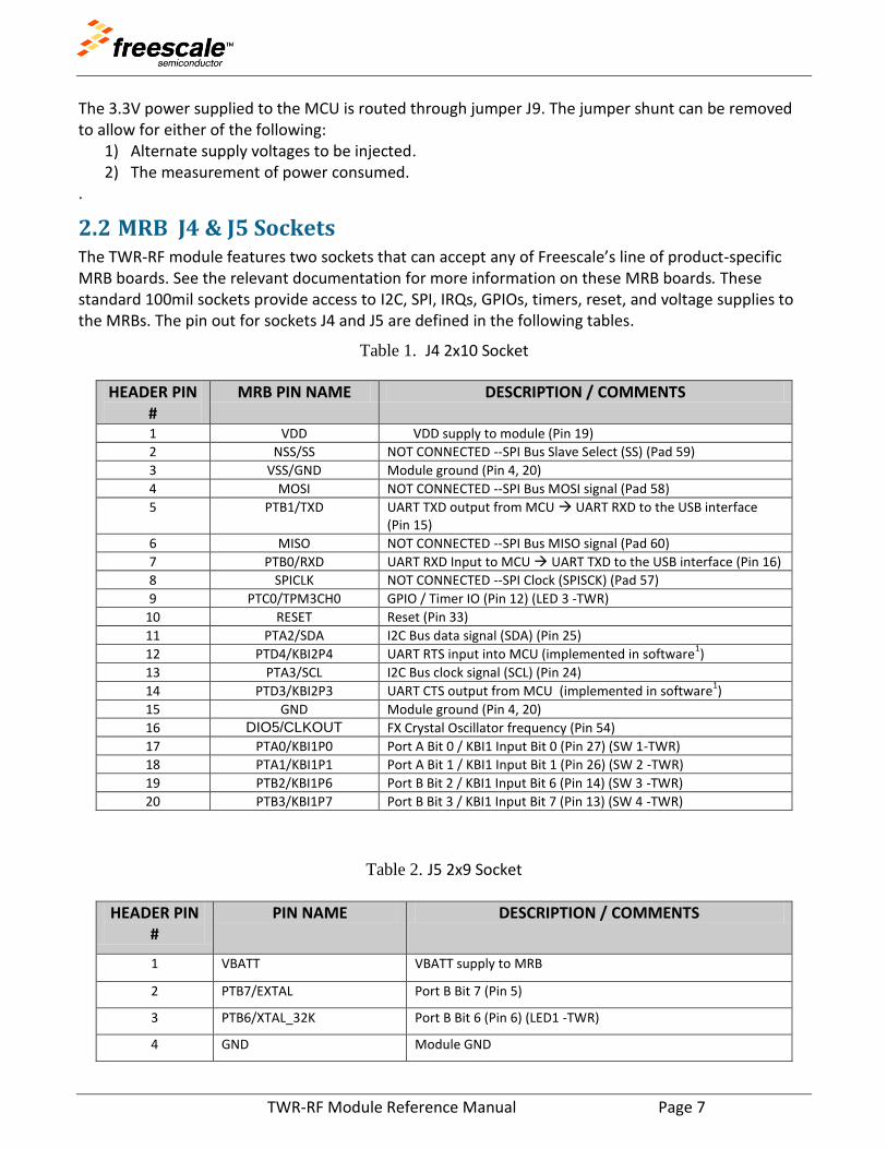
2.2 MRB J4 & J5 Sockets The TWR-RF module features two sockets that can accept any of Freescale’s line of product-specific MRB boards. See the relevant documentation for more information on these MRB boards. These standard 100mil sockets provide access to I2C, SPI, IRQs, GPIOs, timers, reset, and voltage supplies to the MRBs. The pin out for sockets J4 and J5 are defined in the following tables.
Table 1. J4 2x10 Socket
HEADER PIN #
MRB PIN NAME DESCRIPTION / COMMENTS
1 VDD VDD supply to module (Pin 19)
2 NSS/SS NOT CONNECTED --SPI Bus Slave Select (SS) (Pad 59)
3 VSS/GND Module ground (Pin 4, 20)
4 MOSI NOT CONNECTED --SPI Bus MOSI signal (Pad 58)
5 PTB1/TXD UART TXD output from MCU UART RXD to the USB interface (Pin 15)
6 MISO NOT CONNECTED --SPI Bus MISO signal (Pad 60)
7 PTB0/RXD UART RXD Input to MCU UART TXD to the USB interface (Pin 16)
8 SPICLK NOT CONNECTED --SPI Clock (SPISCK) (Pad 57)
9 PTC0/TPM3CH0 GPIO / Timer IO (Pin 12) (LED 3 -TWR)
10 RESET Reset (Pin 33)
11 PTA2/SDA I2C Bus data signal (SDA) (Pin 25)
12 PTD4/KBI2P4 UART RTS input into MCU (implemented in software1)
13 PTA3/SCL I2C Bus clock signal (SCL) (Pin 24)
14 PTD3/KBI2P3 UART CTS output from MCU (implemented in software1)
15 GND Module ground (Pin 4, 20)
16 DIO5/CLKOUT FX Crystal Oscillator frequency (Pin 54)
17 PTA0/KBI1P0 Port A Bit 0 / KBI1 Input Bit 0 (Pin 27) (SW 1-TWR)
18 PTA1/KBI1P1 Port A Bit 1 / KBI1 Input Bit 1 (Pin 26) (SW 2 -TWR)
19 PTB2/KBI1P6 Port B Bit 2 / KBI1 Input Bit 6 (Pin 14) (SW 3 -TWR)
20 PTB3/KBI1P7 Port B Bit 3 / KBI1 Input Bit 7 (Pin 13) (SW 4 -TWR)
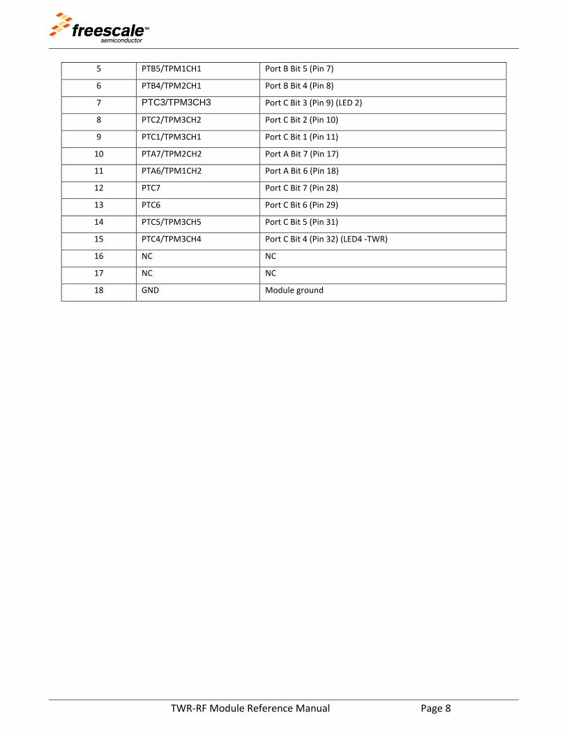
Table 2. J5 2x9 Socket
HEADER PIN #
PIN NAME DESCRIPTION / COMMENTS
1 VBATT VBATT supply to MRB
2 PTB7/EXTAL Port B Bit 7 (Pin 5)
3 PTB6/XTAL_32K Port B Bit 6 (Pin 6) (LED1 -TWR)
4 GND Module GND
TWR-RF Module Reference Manual Page 8
5 PTB5/TPM1CH1 Port B Bit 5 (Pin 7)
6 PTB4/TPM2CH1 Port B Bit 4 (Pin 8)
7 PTC3/TPM3CH3 Port C Bit 3 (Pin 9) (LED 2)
8 PTC2/TPM3CH2 Port C Bit 2 (Pin 10)
9 PTC1/TPM3CH1 Port C Bit 1 (Pin 11)
10 PTA7/TPM2CH2 Port A Bit 7 (Pin 17)
11 PTA6/TPM1CH2 Port A Bit 6 (Pin 18)
12 PTC7 Port C Bit 7 (Pin 28)
13 PTC6 Port C Bit 6 (Pin 29)
14 PTC5/TPM3CH5 Port C Bit 5 (Pin 31)
15 PTC4/TPM3CH4 Port C Bit 4 (Pin 32) (LED4 -TWR)
16 NC NC
17 NC NC
18 GND Module ground

TWR-RF Module Reference Manual Page 9
2.3 GPIO Customer Access The TWR-RF provides a standard 100mil 3x12 header to allow routing to the ON board hardware or to the lateral Tower system connectors. Jumpers may be installed for normal operation to use the on-board hardware. See the following table for connector J6 signal connections.
Table 3. J6 3x12 Header
HEADER PIN #
PIN NAME
DESCRIPTION / COMMENTS
1 UART_TXD_RF_TWR On board TXD from USB-UART transceiver IC
2 PTB1/TXD MRB UART TXD
3 UART_TXD_TWR UART TXD Tower Primary / Secondary Conn (A42)
4 UART_RXD_RF_TWR On board RXD from USB-UART transceiver IC
5 PTB0/RXD MRB UART RXD
6 UART_RXD_TWR UART RXD Tower Primary / Secondary Conn (A41)
7 UART_CTS_RF_TWR On board CTS from USB-UART transceiver IC
8 PTD3/KBI2P3 MRB UART CTS
9 UART_ CTS_TWR UART CTS Tower Primary / Secondary Conn (A9)
10 UART_RTS_RF_TWR On board RTS from USB-UART transceiver IC
11 PTD4/KBI2P4 MRB UART RTS
12 UART_ RTS _TWR UART RTS Tower Primary / Secondary Conn (B21)
13 SW1_RF_TWR On board SW1
14 PTA0/KBI1P0 MRB J4-17
15 SW1_TWR Tower Primary / Secondary Conn (A45)
16 SW2_RF_TWR On board SW2
17 PTA1/KBI1P1 MRB J4-18
18 SW2_TWR Tower Primary / Secondary Conn (A46)
19 SW3_RF_TWR On board SW3
20 PTB2/KBI1P6 MRB J4-19
21 SW3_TWR Tower Primary / Secondary Conn (A47)
22 SW4_RF_TWR On board SW4
23 PTB3/KBI1P7 MRB J4-20
24 SW4_TWR Tower Primary / Secondary Conn (A48)
25 LED1_RF_TWR On board LED1
26 PTB6/XTAL_32K MRB J6- 3
27 LED1_TWR Tower Primary / Secondary Conn (A50)
28 LED2_RF_TWR On board LED2
29 PTC3/TPM3CH3 MRB J5-7
TWR-RF Module Reference Manual Page 10
30 LED2_TWR Tower Primary / Secondary Conn (A51)
31 LED3_RF_TWR On board LED3
32 PTC0/TPM3CH0 MRB J4-9
33 LED3_TWR Tower Primary / Secondary Conn (A52)
34 LED4_RF_TWR On board LED4
35 PTC4/TPM3CH4 MRB J5-15
36 LED4_TWR Tower Primary / Secondary Conn (A53)
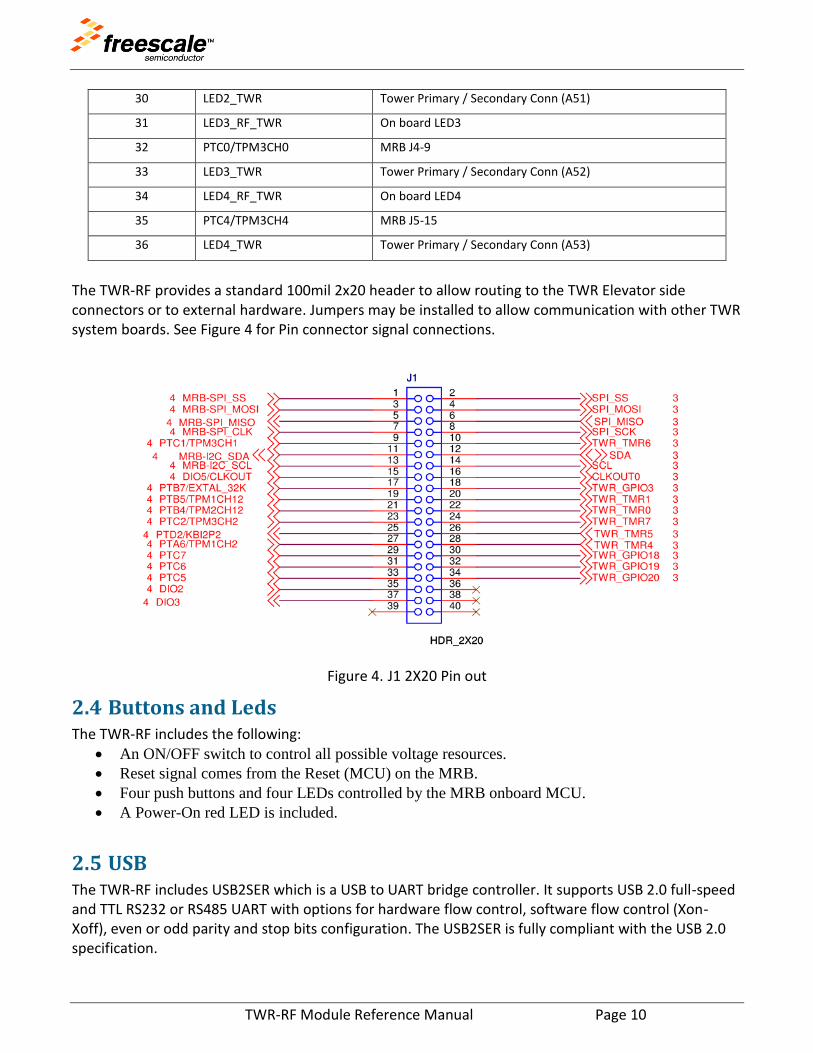
The TWR-RF provides a standard 100mil 2x20 header to allow routing to the TWR Elevator side connectors or to external hardware. Jumpers may be installed to allow communication with other TWR system boards. See Figure 4 for Pin connector signal connections.
Figure 4. J1 2X20 Pin out
2.4 Buttons and Leds The TWR-RF includes the following:
An ON/OFF switch to control all possible voltage resources.
Reset signal comes from the Reset (MCU) on the MRB.
Four push buttons and four LEDs controlled by the MRB onboard MCU.
A Power-On red LED is included.
2.5 USB The TWR-RF includes USB2SER which is a USB to UART bridge controller. It supports USB 2.0 full-speed and TTL RS232 or RS485 UART with options for hardware flow control, software flow control (Xon-Xoff), even or odd parity and stop bits configuration. The USB2SER is fully compliant with the USB 2.0 specification.

TWR-RF Module Reference Manual Page 11
3 Tower Elevator Connections
The TWR-RF features two expansion card-edge connectors that interface to the Primary and Secondary Elevator boards in a Tower system. The following tables Table 4 provide the pin outs for the Primary and Secondary Connectors.
Table 4. TWR-RF Primary Connector Pin out TWR Primary
Connector
Side B Side A
Pin # Name Group Usage Used Jmp Pin # Name Group Usage Used Jmp
B1 5V Power 5.0V Power X X A1 5V Power 5.0V Power
X X
B2 GND Power Ground X A2 GND Power Ground X
B3 3.3V Power 3.3V Power X X A3 3.3V Power 3.3V Power
X X
B4 ELE_PS_SENSE Power Elevator Power Sense
A4 3.3V Power 3.3V Power
X X
B5 GND Power Ground X A5 GND Power Ground X
B6 GND Power Ground X A6 GND Power Ground X
B7 SPI1_CLK / SDHC1_CLK
SPI 1 / SDHC1
SPI_SCK (J4-8)
X X A7 SCL0 I2C 0 SCL (J4-13)
X X
B8 SPI1_CS1 / SDHC1_CS1
SPI 1 / SDHC1
SPI_SS (J4-2) X X A8 SDA0 I2C 0 SDA (J4-11)
X X
B9 SPI1_CS0 / SDHC1_CS0
SPI 1 / SDHC1
SPI_SS (J4-2) X X A9 GPIO9 / CTS1
GPIO/ UART
UART CTS (J6 -9)
X X
B10 SPI1_MOSI / SDHC1_CMD
SPI 1 / SDHC1
SPI_MOSI (J4-4)
X X A10 GPIO8 /
SDHC_D2
GPIO/ SDHC1
B11 SPI1_MISO / SDHC1_D0
SPI 1 / SDHC1
SPI_MISO (J4-6)
X X A11 GPIO7 /
SD_WP_DET
GPIO/ SD / SDHC1
Mechanical Key
B12 ETH_COL Ethernet A12 ETH_CRS
Ethernet
B13 ETH_RXER Ethernet A13 ETH_MDC
Ethernet
B14 ETH_TXCLK Ethernet A14 ETH_MDIO
Ethernet
B15 ETH_TXEN Ethernet A15 ETH_RXCLK
Ethernet
B16 ETH_TXER Ethernet A16 ETH_RXDV
Ethernet
B17 ETH_TXD3 Ethernet A17 ETH_RXD3
Ethernet
B18 ETH_TXD2 Ethernet A18 ETH_RXD2
Ethernet
B19 ETH_TXD1 Ethernet A19 ETH_RXD1
Ethernet

TWR-RF Module Reference Manual Page 12
B20 ETH_TXD0 Ethernet A20 ETH_RXD0
Ethernet
B21 GPIO1 / RTS1 GPIO/ UART
UART_RTS (J6- 12)
X X A21 SSI_MCLK
SSI
B22 GPIO2 / SDHC1_D1
GPIO/ SDHC1
X X A22 SSI_BCLK
SSI
B23 GPIO3 GPIO J1-18 X X A23 SSI_FS SSI
B24 CLKIN0 Clock A24 SSI_RXD
SSI
B25 CLKOUT1 Clock A25 SSI_TXD
SSI
B26 GND Power Ground X A26 GND Power Ground X
B27 AN7 ADC A27 AN3 ADC
B28 AN6 ADC A28 AN2 ADC
B29 AN5 ADC A29 AN1 ADC
B30 AN4 ADC A30 AN0 ADC
B31 GND Power Ground X A31 GND Power Ground X
B32 DAC1 DAC A32 DAC0 DAC
B33 TMR3 Timer A33 TMR1 Timer J1-20 X X
B34 TMR2 Timer A34 TMR0 Timer J1-22 X X
B35 GPIO4 GPIO A35 GPIO6 GPIO
B36 3.3V Power 3.3V Power X A36 3.3V Power 3.3V Power
X
B37 PWM7 PWM A37 PWM3 PWM
B38 PWM6 PWM A38 PWM2 PWM
B39 PWM5 PWM A39 PWM1 PWM
B40 PWM4 PWM A40 PWM0 PWM
B41 CANRX CAN A41 RXD0 UART 0
B42 CANTX CAN A42 TXD0 UART 0
B43 1WIRE 1-Wire A43 RXD1 UART 1 J6 -6 X X
B44 SPI0_MISO SPI 0 A44 TXD1 UART 1 J6-3 X X
B45 SPI0_MOSI SPI 0 A45 VSSA
B46 SPI0_CS0 SPI 0 A46 VDDA
B47 SPI0_CS1 SPI 0 A47 VREFA1
B48 SPI0_CLK SPI 0 A48 VREFA1
B49 GND Power Ground X A49 GND Power Ground X
B50 SCL1 I2C 1 A50 GPIO14
GPIO LED 3 (J6-27)
X X
B51 SDA1 I2C 1 A51 GPIO15
GPIO LED 3 (J6-30)
X X
B52 GPIO5 / SD_CARD_DET
GPIO/ SD / SDHC1
A52 GPIO16
GPIO LED 3 (J6-33)
X X
B53 USB0_DP_PDOWN
USB 0 A53 GPIO17
GPIO LED 3 (J6-36)
X X
B54 USB0_DM_PDOWN
USB 0 A54 USB0_DM
USB 0

TWR-RF Module Reference Manual Page 13
B55 IRQ_H Interrupt A55 USB0_DP
USB 0
B56 IRQ_G Interrupt A56 USB0_ID
USB 0
B57 IRQ_F Interrupt A57 USB0_VBUS
USB 0
B58 IRQ_E Interrupt A58 TMR7 Timer J1-24 X X
B59 IRQ_D Interrupt A59 TMR6 Timer J1-10 X X
B60 IRQ_C Interrupt A60 TMR5 Timer J1-26 X X
B61 IRQ_B Interrupt A61 TMR4 Timer J1-28 X X
B62 IRQ_A Interrupt A62 RSTIN_b
Reset RSTb (J4-10)
X
B63 EBI_ALE/EBI_CS1_b
EBI A63 RSTOUT_b
Reset
B64 EBI_CS0_b EBI A64 CLKOUT0
Clock J1-16 X X
B65 GND Power Ground X A65 GND Power Ground X
B66 EBI_AD15 EBI A66 EBI_AD14
EBI
B67 EBI_AD16 EBI A67 EBI_AD13
EBI
B68 EBI_AD17 EBI A68 EBI_AD12
EBI
B69 EBI_AD18 EBI A69 EBI_AD11
EBI
B70 EBI_AD19 EBI A70 EBI_AD10
EBI
B71 EBI_R/W_b EBI A71 EBI_AD9
EBI
B72 EBI_OE_b EBI A72 EBI_AD8
EBI
B73 EBI_D7 EBI A73 EBI_AD7
EBI
B74 EBI_D6 EBI A74 EBI_AD6
EBI
B75 EBI_D5 EBI A75 EBI_AD5
EBI
B76 EBI_D4 EBI A76 EBI_AD4
EBI
B77 EBI_D3 EBI A77 EBI_AD3
EBI
B78 EBI_D2 EBI A78 EBI_AD2
EBI
B79 FB_D1 Flexbus A79 FB_AD1
Flexbus
B80 FB_D0 Flexbus A80 FB_AD0
Flexbus
B81 GND Power Ground X A81 GND Power Ground X
B82 3.3V Power 3.3V Power X A82 3.3V Power 3.3V Power
X

TWR-RF Module Reference Manual Page 14
TWR-802154
Secondary Connector
Side B Side A
Pin # Name Group Usage Used Jmp Pin # Name Group Usage Used Jmp
D1 5V Power 5.0V Power X X C1 5V Power 5.0V Power
X X
D2 GND Power Ground X C2 GND Power Ground X
D3 3.3V Power 3.3V Power X X C3 3.3V Power 3.3V Power
X X
D4 ELE_PS_SENSE Power Elevator Power Sense
C4 3.3V Power 3.3V Power
X X
D5 GND Power Ground X C5 GND Power Ground X
D6 GND Power Ground X C6 GND Power Ground X
D7 SPI2_CLK SPI 2 C7 SCL2 I2C 2
D8 SPI2_CS1 SPI 2 C8 SDA2 I2C 2
D9 SPI2_CS0 SPI 2 C9 GPIO25
GPIO SW 1 (J6-16)
X X
D10 SPI2_MOSI SPI 2 C10 USB_STOP
ULPI
D11 SPI2_MISO SPI 2 C11 USB_CLK
ULPI
Mechanical Key
D12 ETH_COL Ethernet C12 GPIO26
GPIO SW 2 (J6-18)
X X
D13 ETH_RXER Ethernet C13 ETH_MDC
Ethernet
D14 ETH_TXCLK Ethernet C14 ETH_MDIO
Ethernet
D15 ETH_TXEN Ethernet C15 ETH_RXCLK
Ethernet
D16 GPIO18 GPIO J1-30 X X C16 ETH_RXDV
Ethernet
D17 GPIO19 GPIO J1-32 X X C17 GPIO27
GPIO
D18 GPIO20 GPIO J1-34 X X C18 GPIO28
GPIO
D19 ETH_TXD1 Ethernet C19 ETH_RXD1
Ethernet
D20 ETH_TXD0 Ethernet C20 ETH_RXD0
Ethernet
D21 ULPI_NEXT/USB1_DM
ULPI / USB 1
C21 ULPI_DATA0/USB3_
DM
ULPI / USB 3
D22 ULPI_DIR/USB1_DP
ULPI / USB 1
C22 ULPI_DATA1/USB3_
DP
ULPI / USB 3

TWR-RF Module Reference Manual Page 15
D23 UPLI_DATA5/USB2_DM
ULPI / USB 2
C23 ULPI_DATA2/USB4_
DM
ULPI / USB 4
D24 ULPI_DATA6/USB2_DP
ULPI / USB 2
C24 ULPI_DATA3/USB4_
DP
ULPI / USB 4
D25 ULPI_DATA7 ULPI C25 ULPI_DATA4
ULPI
D26 GND Power Ground X C26 GND Power Ground X
D27 LCD_HSYNC / LCD24
Display C27 AN11 ADC
D28 LCD_VSYNC / LCD25
Display C28 AN10 ADC
D29 AN13 ADC C29 AN9 ADC
D30 AN12 ADC C30 AN8 ADC
D31 GND Power Ground X C31 GND Power Ground X
D32 LCD_CLK / LCD26
Display C32 GPIO29
GPIO SW 3 (J6-21)
X X
D33 TMR11 Timer C33 TMR9 Timer
D34 TMR10 Timer C34 TMR8 Timer
D35 GPIO21 GPIO C35 GPIO30
GPIO SW 4 (J6-24)
X X
D36 3.3V Power 3.3V Power X X C36 3.3V Power 3.3V Power
X X
D37 PWM15 PWM C37 PWM11
PWM
D38 PWM14 PWM C38 PWM10
PWM
D39 PWM13 PWM C39 PWM9 PWM
D40 PWM12 PWM C40 PWM8 PWM
D41 CANRX1 CAN C41 RXD2 / TSI0
UART 2 / TSI
D42 CANTX1 CAN C42 TXD2 / TSI1
UART 2 / TSI
D43 GPIO22 GPIO C43 RTS2 / TSI2
UART 2 / TSI
D44 LCD_OE / LCD27
Display C44 CTS2 / TSI3
UART 2 / TSI
D45 LCD_D0 / LCD0 Display C45 RXD3 / TSI4
UART 3 / TSI
D46 LCD_D1 / LCD1 Display C46 TXD3 / TSI5
UART 3 / TSI
D47 LCD_D2 / LCD2 Display C47 RTS3 / TSI6
UART 3 / TSI
D48 LCD_D3 / LCD3 Display C48 CTS3 / TSI7
UART 3 / TSI
D49 GND Power Ground X C49 GND Power Ground X
D50 GPIO23 GPIO C50 LCD_D4 /
Display

TWR-RF Module Reference Manual Page 16
LCD4
D51 GPIO24 GPIO C51 LCD_D5 /
LCD5
Display
D52 LCD_D12 / LCD12
Display C52 LCD_D6 /
LCD6
Display
D53 LCD_D13 / LCD13
Display C53 LCD_D7 /
LCD7
Display
D54 LCD_D14 / LCD14
Display C54 LCD_D8 /
LCD8
Display
D55 IRQ_P/SPI2_CS2
Interrupt / SPI 2
C55 LCD_D9 /
LCD9
Display
D56 IRQ_O/SPI2_CS3
Interrupt / SPI 2
C56 LCD_D10 /
LCD10
Display
D57 IRQ_N Interrupt C57 LCD_D11 /
LCD11
Display
D58 IRQ_M Interrupt C58 TMR16 Timer
D59 IRQ_L Interrupt C59 TMR15 Timer
D60 IRQ_K Interrupt C60 TMR14 Timer
D61 IRQ_J Interrupt C61 TMR13 Timer
D62 IRQ_I Interrupt C62 LCD_D15 /
LCD15
Display
D63 LCD_D18 / LCD18
Display C63 LCD_D16 /
LCD16
Display
D64 LCD_D19 / LCD19
Display C64 LCD_D17 /
LCD17
Display
D65 GND Power Ground X C65 GND Power Ground X
D66 EBI_AD20 / LCD42
External Bus
Interface / Display
C66 EBI_BE3 /
LCD28
External Bus
Interface / Display
D67 EBI_AD21 / LCD43
External Bus
Interface / Display
C67 EBI_BE2 /
LCD29
External Bus
Interface / Display
D68 EBI_AD22 / LCD44
External Bus
Interface / Display
C68 EBI_BE1 /
LCD30
External Bus
Interface / Display
D69 EBI_AD23 / LCD45
External Bus
Interface / Display
C69 EBI_BE0 /
LCD31
External Bus
Interface / Display

TWR-RF Module Reference Manual Page 17
D70 EBI_AD24 / LCD46
External Bus
Interface / Display
C70 EBI_TSIZE0 / LCD32
External Bus
Interface / Display
D71 EBI_AD25 / LCD47
External Bus
Interface / Display
C71 EBI_TSIZE1 / LCD33
External Bus
Interface / Display
D72 EBI_AD26 / LCD48
External Bus
Interface / Display
C72 EBI_TS /
LCD34
External Bus
Interface / Display
D73 EBI_AD27 / LCD49
External Bus
Interface / Display
C73 EBI_TBST /
LCD35
External Bus
Interface / Display
D74 EBI_AD28 / LCD50
External Bus
Interface / Display
C74 TB_TA /
LCD36
External Bus
Interface / Display
D75 EBI_AD29 / LCD51
External Bus
Interface / Display
C75 EBI_CS4 /
LCD37
External Bus
Interface / Display
D76 EBI_AD30 / LCD52
External Bus
Interface / Display
C76 EBI_CS3 /
LCD38
External Bus
Interface / Display
D77 EBI_AD31 / LCD53
External Bus
Interface / Display
C77 EBI_CS2 /
LCD39
External Bus
Interface / Display
D78 LCD_D20 / LCD20
Display C78 EBI_CS1 /
LCD40
External Bus
Interface / Display
D79 LCD_D21 / LCD21
Display C79 GPIO31 /
LCD41
GPIO
D80 LCD_D22 / LCD22
Display C80 LCD_D23 /
LCD23
Display
D81 GND Power Ground X C81 GND Power Ground X
D82 3.3V Power 3.3V Power X X C82 3.3V Power 3.3V Power
X X
TWR-RF Module Reference Manual Page 18
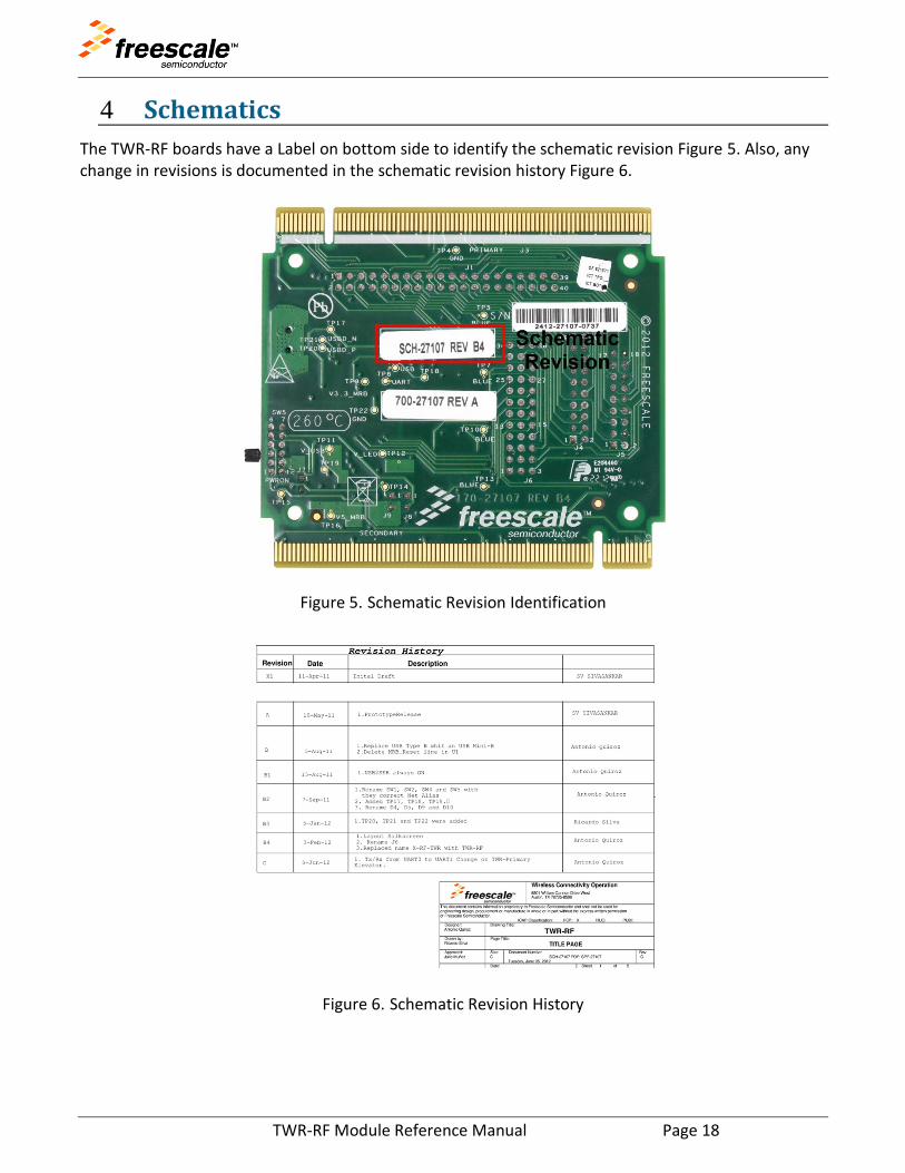
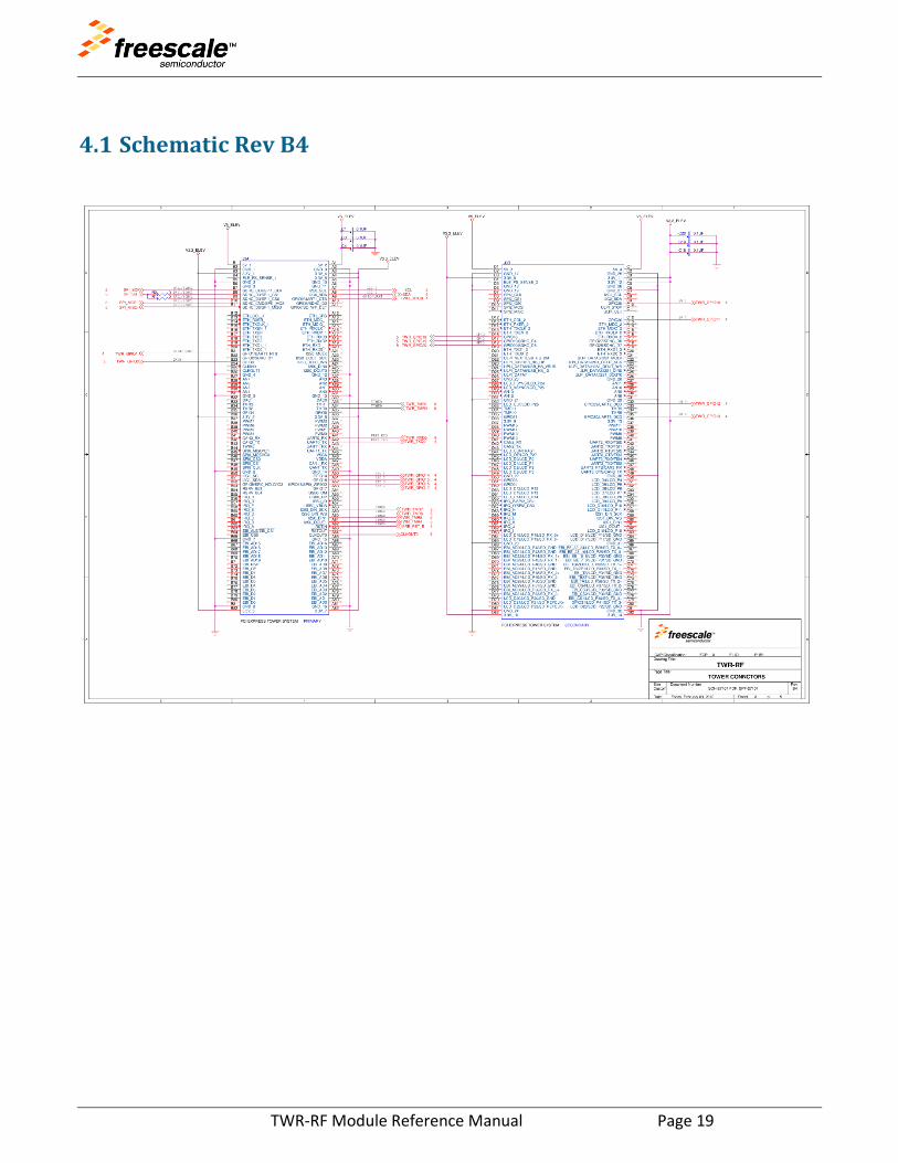
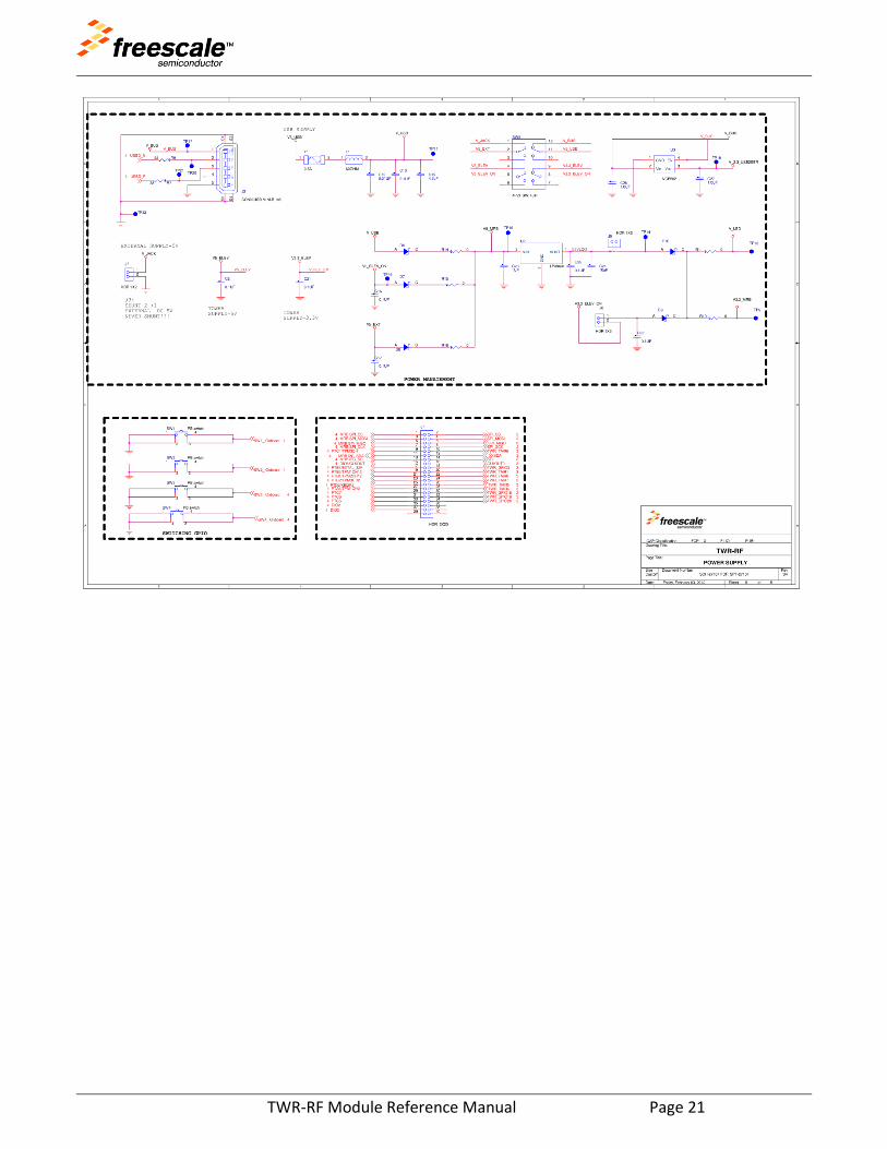
4 Schematics
The TWR-RF boards have a Label on bottom side to identify the schematic revision Figure 5. Also, any change in revisions is documented in the schematic revision history Figure 6.
Figure 5. Schematic Revision Identification
Figure 6. Schematic Revision History
TWR-RF Module Reference Manual Page 19
4.1 Schematic Rev B4

TWR-RF Module Reference Manual Page 20
TWR-RF Module Reference Manual Page 21

TWR-RF Module Reference Manual Page 22
4.2 Schematic Rev C

TWR-RF Module Reference Manual Page 23

TWR-RF Module Reference Manual Page 24

Document Number: TWRRFRMRev. 4.002/2014
Information in this document is provided solely to enable system and software
implementers to use Freescale products. There are no express or implied copyright
licenses granted hereunder to design or fabricate any integrated circuits based on the
information in this document.
Freescale reserves the right to make changes without further notice to any products
herein. Freescale makes no warranty, representation, or guarantee regarding the
suitability of its products for any particular purpose, nor does Freescale assume any
liability arising out of the application or use of any product or circuit, and specifically
disclaims any and all liability, including without limitation consequential or incidental
damages. “Typical” parameters that may be provided in Freescale data sheets and/or
specifications can and do vary in different applications, and actual performance may
vary over time. All operating parameters, including “typicals,” must be validated for each
customer application by customer’s technical experts. Freescale does not convey any
license under its patent rights nor the rights of others. Freescale sells products pursuant
to standard terms and conditions of sale, which can be found at the following address:
freescale.com/SalesTermsandConditions.
How to Reach Us:
Home Page: freescale.com
Web Support: freescale.com/support
Freescale and the Freescale logo are trademarks of Freescale Semiconductor, Inc.,
Reg. U.S. Pat. & Tm. Off. Toweris a trademark of Freescale Semiconductor, Inc. All
other product or service names are the property of their respective owners.
© 2014 Freescale Semiconductor, Inc.