two-stage competition cheater - holley
TRANSCRIPT

Multiple-Carburetor Competition Cheater Kit Number: 02010NOS
Two-Stage Competition Cheater Kit Numbers: 02201NOS and 02202NOS
OWNER’S MANUAL P/N A5052-1-SNOS
NOTICE: Installation of Nitrous Oxide Systems Inc. products signifies that you have read this document and have agreed to
the terms stated within.
It is the purchaser’s responsibility to follow all installation instruction guidelines and safety procedures supplied with the product as it is received by the purchaser to determine the compatibility of the product with the vehicle or the device the purchaser intends to install the product on. Nitrous Oxide Systems Inc. assumes no responsibility for damages occurring from accident, misuse, abuse, improper installation, improper operation, lack of reasonable care, or all previously stated reasons resulting from incompatibility with other manufacturers’ products. Nitrous Oxide Systems Inc. assumes no responsibility or liability for damages incurred by the use of products manufactured or sold by Nitrous Oxide Systems Inc. on vehicles used for competition or racing. Nitrous Oxide Systems Inc. neither recommends nor condones the use of products manufactured or sold by Nitrous Oxide Systems Inc. on vehicles, which may be driven on public roads or highways, and assumes no responsibility for damages incurred by such use. NOS nitrous oxide is legal for use in most states when used in accordance with state and local traffic laws. NOS does not recommend or condone the use of its products in illegal racing activities. NOS has not pursued California Air Research Board (CARB) exemptions for these kits, hence, they are not legal for use on pollution-controlled vehicles in California. A correctly installed NOS nitrous system should not alter the emission control performance of your vehicle under standard EPA test cycle conditions. NOTICE: The NOS Multiple-Carburetor and Two Stage Competition Cheater system kit is not intended for use on hatchback
type vehicles without the use of NOS part numbers 16160NOS (External Aluminum Blow-Down Tube) and 16169NOS (Racer Safety Pressure Relief Cap).
2
HAZARDS DEFINED
This manual presents step-by-step instructions that describe the process of installing your NOS Nitrous Oxide Injection System. These procedures provide a framework for installation and operation of this kit. Parts are referenced by name and number to avoid confusion. Within the instructions, you are advised of potential hazards, pitfalls, and problems to avoid. The following examples explain the various hazard levels: WARNING! Failure to comply with instructions may result in injury or death. CAUTION! Failure to comply with instructions may result in damage to equipment.
NOTE: This information is important, needs to be emphasized, and is set apart from the rest of the text.
HINT: These special instructions provide a handy work tip.
NITROUS OXIDE INJECTION SYSTEM SAFETY TIPS
WARNINGS Do not attempt to start the engine if the nitrous has been injected while the engine was not running. Disconnect the coil wire and turn the engine over with the throttle wide open for several revolutions before attempting to start. Failure to do so can result in extreme engine damage. Never permit oil, grease, or any other readily combustible substances to come in contact with cylinders, valves, solenoids, hoses, and fittings. Oil and certain gases (such as oxygen and nitrous oxide) may combine to produce a highly flammable condition. Never interchange nitrous and fuel solenoids. Failure to follow these simple instructions can result in extreme engine damage and/or personal injury. Never drop or violently strike the bottle. Doing so may result in an explosive bottle failure. Never change pressure settings of the safety relief valve on the nitrous bottle valve. Increasing the safety relief valve pressure settings may create an explosive bottle hazard. Identify the gas content by the NOS label on the bottle before using. If the bottle is not identified to show the gas contained, return the bottle to the supplier. Do not deface or remove any markings, which are on the nitrous bottle. Nitrous bottle valves should always be closed when the system is not being used. Notify the supplier of any condition, which might have permitted any foreign matter to enter the valve or bottle. Keep the valves closed on all empty bottles to prevent accidental contamination. After storage, open the nitrous bottle valve for an instant to clear the opening of any possible dust or dirt. It is important that all threads on the valves and solenoids are properly mated. Never force connections that do not fit properly. CONGRATULATIONS on purchasing your NOS Nitrous Oxide Injection System. Your system is composed of the highest quality
components available. It should provide many miles of trouble-free performance when used correctly. If you have any questions regarding the performance of your system, call NOS Technical Service at 1-866-464-6553.
3
TABLE OF CONTENTS WHAT IS NITROUS OXIDE? ..................................................................................................................................................................... 4 Do’s and Don’ts of Nitrous Oxide ............................................................................................................................................................... 4 Chapter 1 Introduction to your NOS Nitrous Oxide Kit .............................................................................................................................. 4
1.1 General Information ......................................................................................................................................................................... 4 1.1.1 Multiple-Carburetor Competition Cheater System ..................................................................................................................... 5
1.2 Competition Cheater System Requirements .................................................................................................................................... 5 1.3 Kit Components ............................................................................................................................................................................... 6
Chapter 2 Kit Installation—Bottle Mounting for all Kits ............................................................................................................................ 10 2.1 Bottle Mounting Instructions ........................................................................................................................................................... 10
2.1.1 Street Vehicles ........................................................................................................................................................................ 10 2.1.2 Racing Vehicles ....................................................................................................................................................................... 10
2.2 Bottle Orientation ........................................................................................................................................................................... 10 2.3 Bottle Installation............................................................................................................................................................................ 11
Chapter 3 Kit Installation—Multiple-Carburetor Competition Cheater System......................................................................................... 11 3.1 Injector Plate Mounting ................................................................................................................................................................... 11 3.2 Solenoid Mounting ......................................................................................................................................................................... 12
3.2.1 Nitrous Solenoid Installation .................................................................................................................................................... 12 3.2.2 Fuel Solenoid Installation ........................................................................................................................................................ 13
3.3 Nitrous Feed Line Mounting ........................................................................................................................................................... 13 3.4 Auxiliary Fuel Line Installation ....................................................................................................................................................... 14 3.5 Electrical System ........................................................................................................................................................................... 14
Chapter 4 Kit Installation—Two-Stage Competition Cheater System ...................................................................................................... 15 4.1 Injector Plate Mounting .................................................................................................................................................................. 15 4.2 Solenoid Mounting ......................................................................................................................................................................... 15
4.2.1 Nitrous Solenoid Installation (First Stage) ............................................................................................................................... 15 4.2.2 Fuel Solenoid Installation (First Stage) .................................................................................................................................... 16 4.2.3 Nitrous Solenoid Installation (Second Stage) .......................................................................................................................... 17 4.2.4 Fuel Solenoid Installation (Second Stage) .............................................................................................................................. 18
4.3 Nitrous Feed Line Mounting ........................................................................................................................................................... 19 4.4 Auxiliary Fuel Line Installation ....................................................................................................................................................... 19 4.5 Electrical System Installation ......................................................................................................................................................... 19 4.6 Electrical System Checkout ........................................................................................................................................................... 21
Chapter 5 Preparing for Operation .......................................................................................................................................................... 21 5.1 Checkout Procedure—Multiple-Carburetor Competition Cheater System ..................................................................................... 21 5.2 Checkout Procedure—Two-Stage Competition Cheater System ................................................................................................... 21
Chapter 6 Tuning Suggestions ................................................................................................................................................................. 22 6.1 Tuning Suggestions—Multiple-Carburetor Competition Cheater System ...................................................................................... 22 6.2 Tuning Suggestions—Two-Stage Competition Cheater Systems .................................................................................................. 22
Chapter 7 Advanced Tuning for Maximum Power ................................................................................................................................... 23 7.1 Optimum Nitrous/Fuel Jetting ........................................................................................................................................................ 23
7.1.1 Determining Optimum Nitrous/Fuel Jetting .............................................................................................................................. 23 7.1.2 Determining Optimum Ignition Timing ..................................................................................................................................... 24
Chapter 8 Routine Maintenance .............................................................................................................................................................. 26 8.1 Nitrous Solenoid Filter .................................................................................................................................................................... 26 8.2 Nitrous Solenoid Plunger ............................................................................................................................................................... 26
8.2.1 General Information ................................................................................................................................................................. 26 8.2.2 Nitrous Solenoid Plunger Disassembly and Inspection ........................................................................................................... 26
Appendix A Troubleshooting Guide ......................................................................................................................................................... 28 Nitrous Oxide Accessories ....................................................................................................................................................................... 30
4
WHAT IS NITROUS OXIDE?
NITROUS OXIDE… …Is a cryogenic gas composed of nitrogen and oxygen molecules …Is 36% oxygen by weight …Is non-flammable by itself …Is stored as a compressed liquid …Exists in two grades—U.S.P. and Nitrous Plus: U.S.P. is medical grade nitrous oxide; its common use is dental and veterinary anesthesia. It is also commonly used as a
propellant in canned whipped cream. U.S.P. is not available to the public. Nitrous Plus differs from U.S.P. in that it contains trace amounts of sulphur dioxide added to prevent substance abuse. Nitrous
Plus is intended for automotive applications and is available for sale to the public
In automotive applications, Nitrous Plus and fuel are injected into the engine’s intake manifold, which produces the following results: Lowers engine intake air temperature, producing a dense inlet charge. Increases the oxygen content of the inlet charge (air is only 22 percent oxygen by weight). Increases the rate at which combustion occurs in the engine’s cylinders.
Do’s and Don’ts of Nitrous Oxide
DO’S Read all instructions before attempting to install your NOS nitrous system. Make sure your fuel delivery system is adequate for the nitrous jetting you have chosen. Inadequate fuel pressure or flow will
result in engine damage. Use 14 gauge (minimum) wire when installing electrical system components. Use high-quality connections at all electrical joints. Use PTFE-based paste on pipe style fittings.
Make sure your engine and related components (ignition, carburetor, and driveline) are in proper working condition. If nitrous is accidentally injected into the engine when it is not running, remove the engine coil wire, open the throttle, and
crank the engine 10 to 15 seconds before starting. Failure to do so can result in an explosive engine failure. Use your NOS nitrous system at wide-open throttle only and at engine speeds above 2500 RPM. Install a proper engine to chassis ground. Failure to do so may result in an explosive failure of the main nitrous supply
line.
Use a high-quality fuel, as suggested in Chapter 3, Baseline Tuning Suggestions.
DON’TS Engage your nitrous system with the engine off. Severe engine damage can occur. Modify NOS nitrous systems (if you need a non-stock item, call NOS Technical Service for assistance). Overtighten AN type fittings. Use PTFE Tape on any pipe threads. Pieces of PTFE tape can break loose and become lodged in nitrous or fuel solenoids or
solenoid filters. Debris lodged in a nitrous or fuel solenoid can cause catastrophic engine failure. Use sealant of any kind on AN type fittings. Inhale nitrous oxide. Death due to suffocation can occur. Allow nitrous oxide to come in contact with skin. Severe frostbite can occur.
Use octane boosters that contain methanol. Fuel solenoid failure may occur, producing severe engine damage.
Chapter 1 Introduction to your NOS Nitrous Oxide Kit
1.1 General Information NOS Multiple-Carburetor Competition Cheater Systems and Two-Stage Competition Cheater Systems are intended for use on modified domestic V-8 engines of at least 350 cubic inch displacement. Horsepower and torque increases will vary with engine displacement and modifications. Approximate power increase estimates can be made, based on the mass flow of nitrous oxide into the engine. The Multiple-Carburetor Competition Cheater System and the Two-Stage Competition Cheater System are described below. Typically, the standard #10 (10 lb.) bottle of nitrous will supply 1 1/2 to 2 minutes of operation at wide-open throttle. A full #10 bottle will weigh 25 lbs. For best performance, the bottle should be refilled when it weighs 17 to 18 lbs.
5
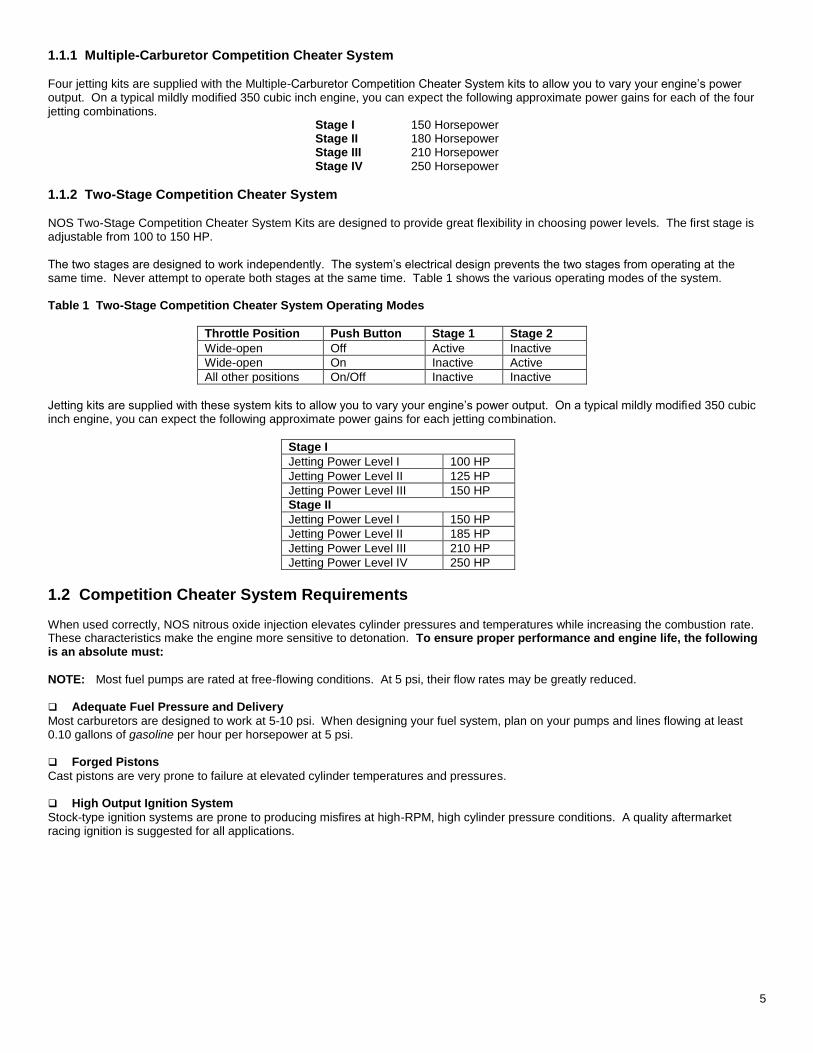
1.1.1 Multiple-Carburetor Competition Cheater System Four jetting kits are supplied with the Multiple-Carburetor Competition Cheater System kits to allow you to vary your engine’s power output. On a typical mildly modified 350 cubic inch engine, you can expect the following approximate power gains for each of the four jetting combinations.
Stage I 150 Horsepower Stage II 180 Horsepower Stage III 210 Horsepower Stage IV 250 Horsepower
1.1.2 Two-Stage Competition Cheater System NOS Two-Stage Competition Cheater System Kits are designed to provide great flexibility in choosing power levels. The first stage is adjustable from 100 to 150 HP. The two stages are designed to work independently. The system’s electrical design prevents the two stages from operating at the same time. Never attempt to operate both stages at the same time. Table 1 shows the various operating modes of the system. Table 1 Two-Stage Competition Cheater System Operating Modes
Throttle Position Push Button Stage 1 Stage 2
Wide-open Off Active Inactive
Wide-open On Inactive Active
All other positions On/Off Inactive Inactive
Jetting kits are supplied with these system kits to allow you to vary your engine’s power output. On a typical mildly modified 350 cubic inch engine, you can expect the following approximate power gains for each jetting combination.
Stage I
Jetting Power Level I 100 HP
Jetting Power Level II 125 HP
Jetting Power Level III 150 HP
Stage II
Jetting Power Level I 150 HP
Jetting Power Level II 185 HP
Jetting Power Level III 210 HP
Jetting Power Level IV 250 HP
1.2 Competition Cheater System Requirements When used correctly, NOS nitrous oxide injection elevates cylinder pressures and temperatures while increasing the combustion rate. These characteristics make the engine more sensitive to detonation. To ensure proper performance and engine life, the following is an absolute must: NOTE: Most fuel pumps are rated at free-flowing conditions. At 5 psi, their flow rates may be greatly reduced. Adequate Fuel Pressure and Delivery
Most carburetors are designed to work at 5-10 psi. When designing your fuel system, plan on your pumps and lines flowing at least 0.10 gallons of gasoline per hour per horsepower at 5 psi. Forged Pistons
Cast pistons are very prone to failure at elevated cylinder temperatures and pressures. High Output Ignition System
Stock-type ignition systems are prone to producing misfires at high-RPM, high cylinder pressure conditions. A quality aftermarket racing ignition is suggested for all applications.
6
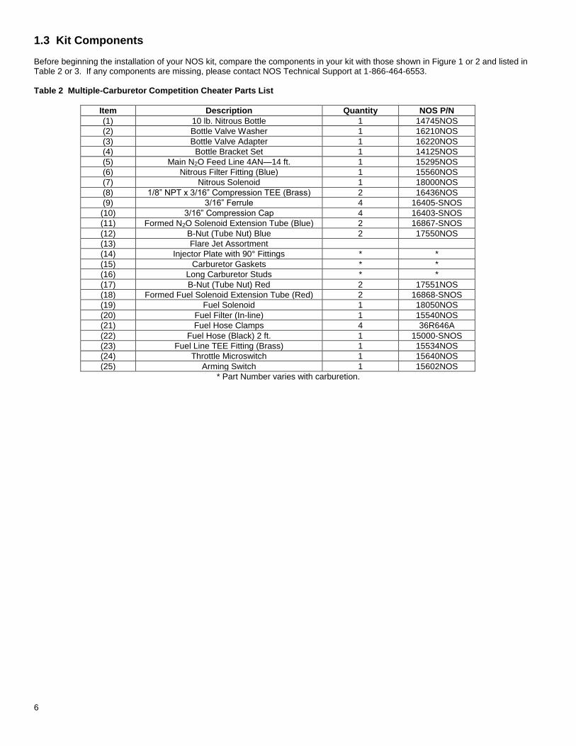
1.3 Kit Components
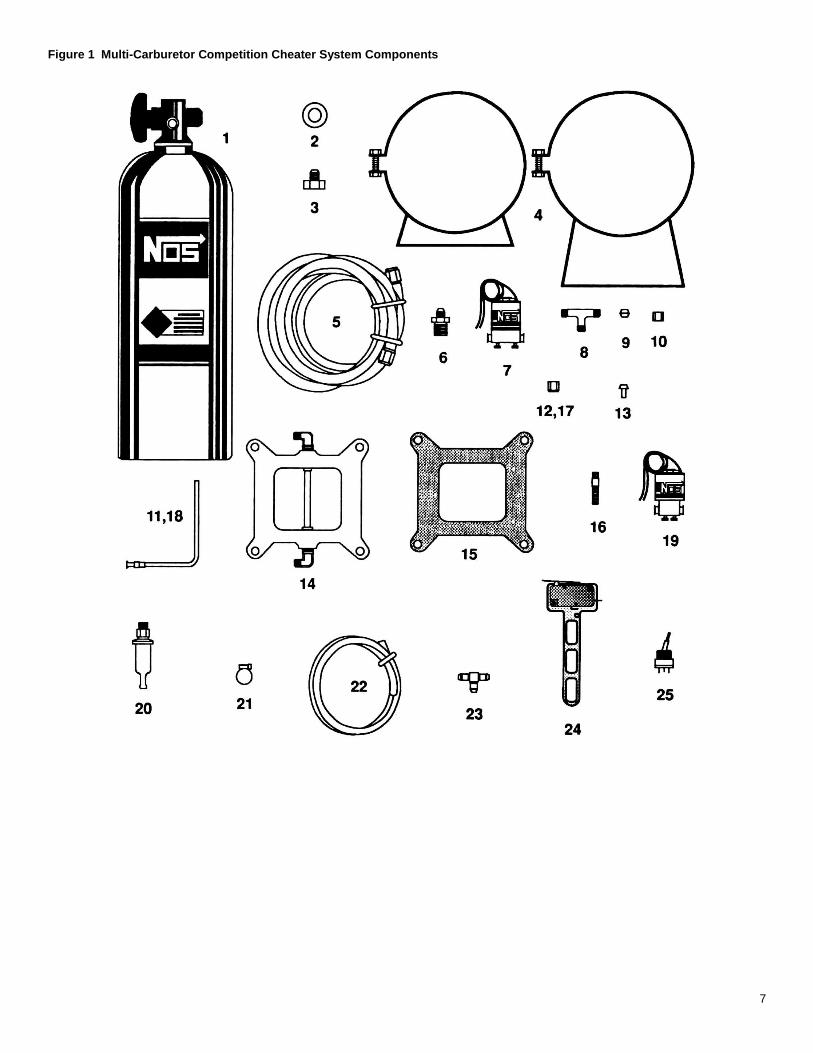
Before beginning the installation of your NOS kit, compare the components in your kit with those shown in Figure 1 or 2 and listed in Table 2 or 3. If any components are missing, please contact NOS Technical Support at 1-866-464-6553. Table 2 Multiple-Carburetor Competition Cheater Parts List
Item Description Quantity NOS P/N
(1) 10 lb. Nitrous Bottle 1 14745NOS
(2) Bottle Valve Washer 1 16210NOS
(3) Bottle Valve Adapter 1 16220NOS
(4) Bottle Bracket Set 1 14125NOS
(5) Main N2O Feed Line 4AN—14 ft. 1 15295NOS
(6) Nitrous Filter Fitting (Blue) 1 15560NOS
(7) Nitrous Solenoid 1 18000NOS
(8) 1/8” NPT x 3/16” Compression TEE (Brass) 2 16436NOS
(9) 3/16” Ferrule 4 16405-SNOS
(10) 3/16” Compression Cap 4 16403-SNOS
(11) Formed N2O Solenoid Extension Tube (Blue) 2 16867-SNOS
(12) B-Nut (Tube Nut) Blue 2 17550NOS
(13) Flare Jet Assortment
(14) Injector Plate with 90° Fittings * *
(15) Carburetor Gaskets * *
(16) Long Carburetor Studs * *
(17) B-Nut (Tube Nut) Red 2 17551NOS
(18) Formed Fuel Solenoid Extension Tube (Red) 2 16868-SNOS
(19) Fuel Solenoid 1 18050NOS
(20) Fuel Filter (In-line) 1 15540NOS
(21) Fuel Hose Clamps 4 36R646A
(22) Fuel Hose (Black) 2 ft. 1 15000-SNOS
(23) Fuel Line TEE Fitting (Brass) 1 15534NOS
(24) Throttle Microswitch 1 15640NOS
(25) Arming Switch 1 15602NOS
* Part Number varies with carburetion.
7
Figure 1 Multi-Carburetor Competition Cheater System Components
8
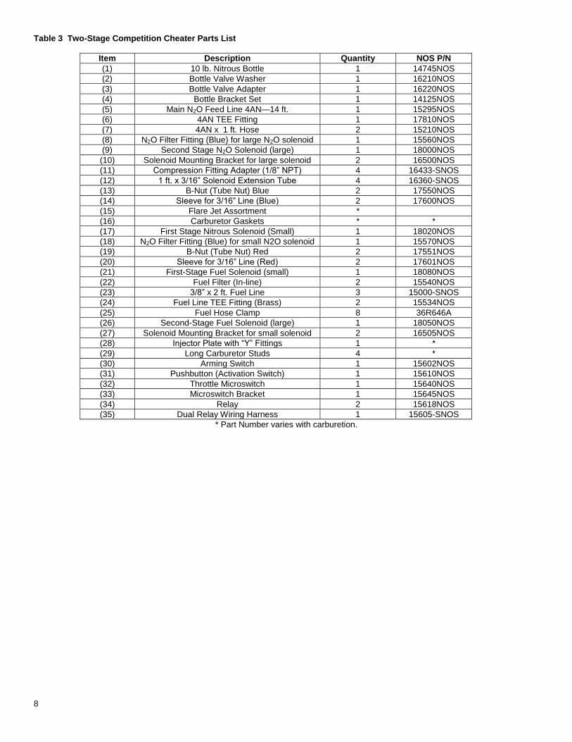
Table 3 Two-Stage Competition Cheater Parts List
Item Description Quantity NOS P/N
(1) 10 lb. Nitrous Bottle 1 14745NOS
(2) Bottle Valve Washer 1 16210NOS
(3) Bottle Valve Adapter 1 16220NOS
(4) Bottle Bracket Set 1 14125NOS
(5) Main N2O Feed Line 4AN—14 ft. 1 15295NOS
(6) 4AN TEE Fitting 1 17810NOS
(7) 4AN x 1 ft. Hose 2 15210NOS
(8) N2O Filter Fitting (Blue) for large N2O solenoid 1 15560NOS
(9) Second Stage N2O Solenoid (large) 1 18000NOS
(10) Solenoid Mounting Bracket for large solenoid 2 16500NOS
(11) Compression Fitting Adapter (1/8” NPT) 4 16433-SNOS
(12) 1 ft. x 3/16” Solenoid Extension Tube 4 16360-SNOS
(13) B-Nut (Tube Nut) Blue 2 17550NOS
(14) Sleeve for 3/16” Line (Blue) 2 17600NOS
(15) Flare Jet Assortment *
(16) Carburetor Gaskets * *
(17) First Stage Nitrous Solenoid (Small) 1 18020NOS
(18) N2O Filter Fitting (Blue) for small N2O solenoid 1 15570NOS
(19) B-Nut (Tube Nut) Red 2 17551NOS
(20) Sleeve for 3/16” Line (Red) 2 17601NOS
(21) First-Stage Fuel Solenoid (small) 1 18080NOS
(22) Fuel Filter (In-line) 2 15540NOS
(23) 3/8” x 2 ft. Fuel Line 3 15000-SNOS
(24) Fuel Line TEE Fitting (Brass) 2 15534NOS
(25) Fuel Hose Clamp 8 36R646A
(26) Second-Stage Fuel Solenoid (large) 1 18050NOS
(27) Solenoid Mounting Bracket for small solenoid 2 16505NOS
(28) Injector Plate with “Y” Fittings 1 *
(29) Long Carburetor Studs 4 *
(30) Arming Switch 1 15602NOS
(31) Pushbutton (Activation Switch) 1 15610NOS
(32) Throttle Microswitch 1 15640NOS
(33) Microswitch Bracket 1 15645NOS
(34) Relay 2 15618NOS
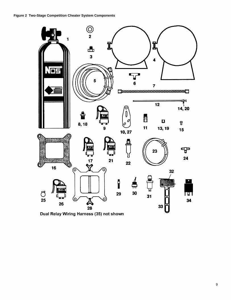
(35) Dual Relay Wiring Harness 1 15605-SNOS
* Part Number varies with carburetion.
9
Figure 2 Two-Stage Competition Cheater System Components
10
Chapter 2 Kit Installation—Bottle Mounting for all Kits
2.1 Bottle Mounting Instructions NOTE: Disconnect the battery ground before beginning installation.
2.1.1 Street Vehicles Accurate calibration of your NOS nitrous system depends on the bottle remaining at a stable temperature. Mount the bottle away from heat sources, such as the engine compartment or exhaust system, and away from windows, where the bottle is exposed to direct sunlight. NOS recommends that the bottle be environmentally separated from the driver’s compartment. Because hatchback-type vehicles generally do not have a firewall between the trunk area and the driver’s compartment, the safety pressure relief cap should be replaced with P/N 16169NOS and P/N 16160NOS should be added. P/N 16160NOS is an aluminum blow-down tube (an –8 neoprene-lined braided hose can be substituted). The blow-down tube should be routed to the exterior of the vehicle (preferably under the vehicle). This procedure will prevent filling the driver’s compartment with a cloud of nitrous oxide if the safety pressure relief cap should happen to rupture for any reason.
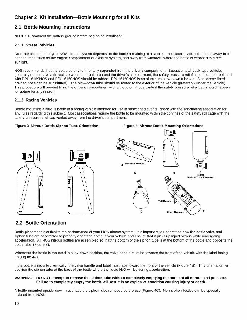
2.1.2 Racing Vehicles Before mounting a nitrous bottle in a racing vehicle intended for use in sanctioned events, check with the sanctioning association for any rules regarding this subject. Most associations require the bottle to be mounted within the confines of the safety roll cage with the safety pressure relief cap vented away from the driver’s compartment. Figure 3 Nitrous Bottle Siphon Tube Orientation Figure 4 Nitrous Bottle Mounting Orientations
2.2 Bottle Orientation
Bottle placement is critical to the performance of your NOS nitrous system. It is important to understand how the bottle valve and siphon tube are assembled to properly orient the bottle in your vehicle and ensure that it picks up liquid nitrous while undergoing acceleration. All NOS nitrous bottles are assembled so that the bottom of the siphon tube is at the bottom of the bottle and opposite the bottle label (Figure 3). Whenever the bottle is mounted in a lay-down position, the valve handle must be towards the front of the vehicle with the label facing up (Figure 4A). If the bottle is mounted vertically, the valve handle and label must face toward the front of the vehicle (Figure 4B). This orientation will position the siphon tube at the back of the bottle where the liquid N2O will be during acceleration. WARNING! DO NOT attempt to remove the siphon tube without completely emptying the bottle of all nitrous and pressure.
Failure to completely empty the bottle will result in an explosive condition causing injury or death.
A bottle mounted upside-down must have the siphon tube removed before use (Figure 4C). Non-siphon bottles can be specially ordered from NOS.
11
If the bottle must be mounted parallel to the axles of the vehicle (sideways), the valve handle and label must be angled at approximately 45° toward the front of the vehicle (Figure 4D). This orientation will position the siphon tube toward the rear of the bottle. NOTE: When using a bottle with a siphon tube, the tall bracket should be at the valve end of the bottle and the short bracket at the
bottom (Figure 4E). The most efficient mounting is the lay-down position (Figure 4A) with the valve handle toward the front of the vehicle. This position allows the greatest amount of liquid to be used before the siphon tube begins to pick up gaseous nitrous oxide.
2.3 Bottle Installation
After you have determined the location and orientation of the nitrous bottle, use the following procedure to install the bottle: NOTE: Numbers in parentheses ( ) refer to the parts list/assembly drawing number for the component. Figure 5 shows the
installation assembly for the Multiple-Carburetor Competition Cheater System. Figure 8 shows the installation assembly for the Two-Stage Competition Cheater System.
1. Install the bottle nut adapter (2) and washer (3) on the nitrous bottle (1), and tighten securely. 2. Loosely install the bottle mounting brackets (4) on the nitrous bottle. 3. Locate the bottle assembly in the desired mounting location, ensuring that the location will provide easy access to the bottle valve,
hose connection, and bracket clamp bolts to facilitate bottle changing. 4. Use the assembled bottle/bracket/blow-down tube unit as a pattern to mark for hole drilling. Drill four 5/16” holes for the bottle
bracket bolts, a 1/2” hole for the blow-down tube, and an 11/16” hole for the nitrous supply line. 5. Mount the brackets securely to the surface (recommended minimum of 5/16” bolts or No. 12 sheet metal screws).
6. Tighten the bracket clamps on the bottle.
Chapter 3 Kit Installation—Multiple-Carburetor Competition Cheater System NOTE: This chapter contains installation instructions for the Multi-Carburetor Competition Cheater. If you are installing the Two-Stage
Competition Cheater System, skip to Chapter 4.
3.1 Injector Plate Mounting
Use the following procedure to install the injector plate (14). Refer to Figure 5 for an illustration of part installation. 1. Remove the carburetor inlet ducting and air cleaner. 2. Disconnect the throttle linkage from the carburetor. 3. Disconnect the fuel line from the carburetor. 4. Remove the carburetor. 5. Remove the stock carburetor studs. 6. Install the extended carburetor studs (16). 7. Install the injector plate (14) and gaskets (15) on the intake manifold with the NOS label facing up. 8. Install the carburetor. 9. Connect the throttle linkage. 10. Repeat steps 1 through 9 for additional carburetors.
12
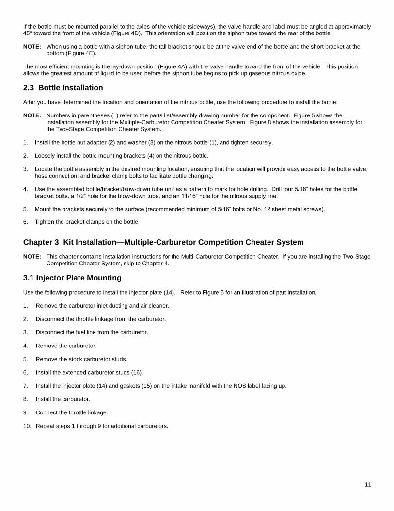
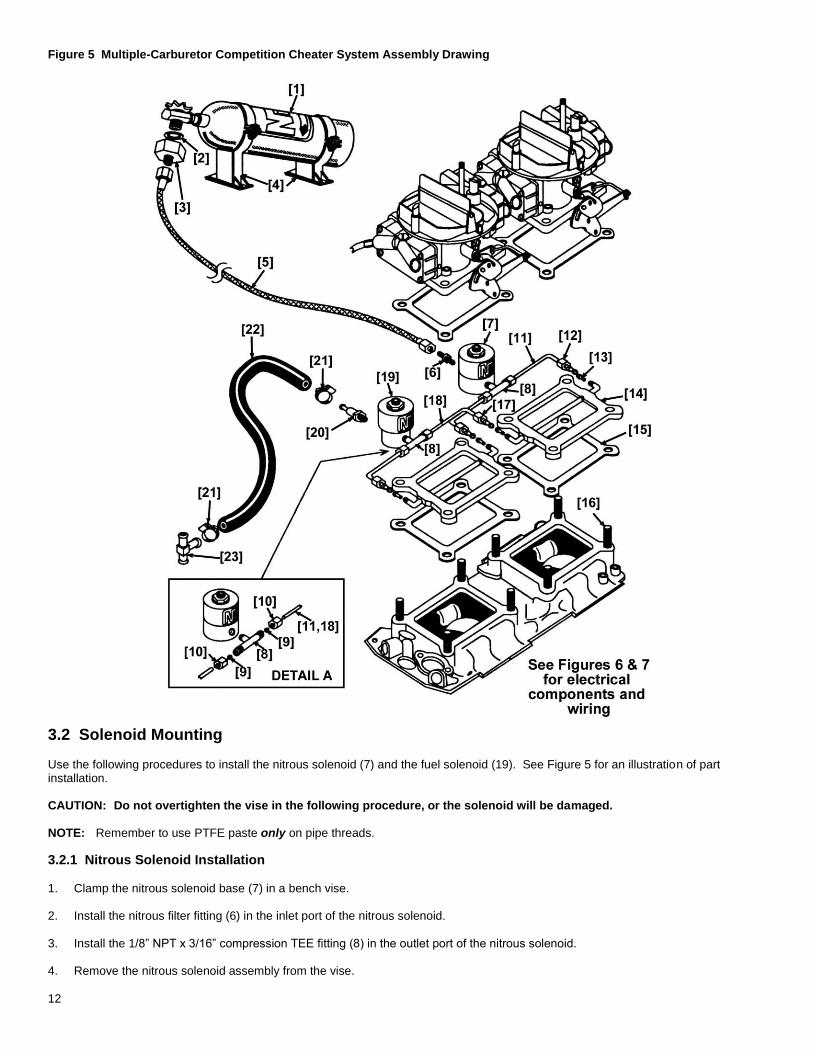
Figure 5 Multiple-Carburetor Competition Cheater System Assembly Drawing
3.2 Solenoid Mounting Use the following procedures to install the nitrous solenoid (7) and the fuel solenoid (19). See Figure 5 for an illustration of part installation. CAUTION: Do not overtighten the vise in the following procedure, or the solenoid will be damaged. NOTE: Remember to use PTFE paste only on pipe threads.
3.2.1 Nitrous Solenoid Installation 1. Clamp the nitrous solenoid base (7) in a bench vise. 2. Install the nitrous filter fitting (6) in the inlet port of the nitrous solenoid. 3. Install the 1/8” NPT x 3/16” compression TEE fitting (8) in the outlet port of the nitrous solenoid. 4. Remove the nitrous solenoid assembly from the vise.
13
5. Install the proper nitrous jet (13) in the blue 90° fitting on the injector plates (See Section 1.1.1), with the beveled edge out. 6. Connect the blue B-Nut (12) on the flared end of the formed nitrous (blue) extension tube (11) to the blue 90° fitting on the injector
plate. 7. Slide the 3/16” compression cap (10) over the open end of the formed nitrous extension tube (11). 8. Place the ferrule (9) in the open end of the formed nitrous extension tube (11). 9. Connect the open end of the formed nitrous extension tube (11) to the nitrous solenoid assembly by tightening the 3/16”
compression cap (10) onto the compression TEE fitting (8), (Detail A, Figure 5). CAUTION! Extension tubes may need to be shortened, depending on application. To shorten the extension tube, place the
solenoid in the desired location, measure the tube to the centerline of the fitting, and cut the tube. Ensure that the tube is free of debris.
10. Repeat steps 6 and 7 for each carburetor nitrous connection.
3.2.2 Fuel Solenoid Installation
CAUTION: Do not overtighten the vise in the following procedure, or the solenoid will be damaged. NOTE: Remember to use PTFE paste only on pipe threads.
1. Clamp the fuel solenoid base (19) in a bench vise. 2. Install the in-line filter (20) in the inlet port of the fuel solenoid. 3. Install the 1/8” NPT x 3/16” compression TEE fitting (8) in the outlet port of the fuel solenoid. 4. Remove the fuel solenoid assembly form the vise. 5. Install the proper fuel jet (13) in the red 90° fitting on the injector plates (See Section 1.1.1), with the beveled edge out. 6. Connect the red B-Nut (17) on the flared end of the formed fuel (red) extension tube (18) to the red 90° fitting on the injector plate. 7. Slide the 3/16” compression cap (10) over the open end of the formed fuel extension tube (18). 8. Place the ferrule (9) in the open end of the formed fuel extension tube (18). 9. Connect the open end of the formed fuel extension tube (18) to the fuel solenoid assembly by tightening the 3/16” compression
cap (10) onto the compression TEE fitting (8), (Detail A, Figure 5). CAUTION! Extension tubes may need to be shortened, depending on application. To shorten the extension tube, place the
solenoid in the desired location, measure the tube to the centerline of the fitting, and cut the tube. Ensure that the tube is free of debris.
10. Repeat steps 6 and 7 for an additional injector plate.
3.3 Nitrous Feed Line Mounting HINT: Most late-model vehicles have access plugs in the trunk floor, which are convenient for line routing. Following the fuel lines
along the underbody, and entering the engine bay through the front fender well between the plastic inner fender and the body, usually works well.
1. Determine the route for your nitrous feed line to follow. Ensure that the path is clear of exhaust system, suspension, steering, wheels, electrical lines and components, and tires.
2. Feed the main nitrous supply line (5) along the proposed route.
3. If it is necessary to support the nitrous supply line under the vehicle, use 1/2” Tinnerman clamps or nylon tie-wraps to support the line securely.
4. Attach the nitrous supply line to the nitrous bottle valve adapter (3). WARNING: Nitrous oxide is dangerous to humans if inhaled or comes in contact with the skin. Always point the nitrous line
opening away from people when purging the line.
14
5. Purge the nitrous supply line. A. Wrap the end of the nitrous line with a rag and hold securely. B. Point the opening away from people.
C. Briefly open the bottle valve. 6. Attach the nitrous supply line to the nitrous filter fitting (6) on the solenoid (7) inlet port.
3.4 Auxiliary Fuel Line Installation Under most operating conditions, it is suggested that a separate 3/8” fuel line and pump be dedicated to the nitrous system. If you choose to use a single-line fuel system to feed both the engine and the nitrous system, follow these instructions, but remember—at higher power levels, this fuel system may be inadequate. To install the supplied auxiliary fuel line hose (22): 1. Choose the location where the primary fuel line is to be tapped. 2. Cut and deburr the primary fuel line. 3. Install the brass fuel line TEE fitting (23) in the primary fuel line and secure both sides with hose clamps (21). 4. Connect one end of the auxiliary fuel line (22) to the base of the brass TEE fitting (23) with a hose clamp (21). 5. Connect the open end of the auxiliary fuel line to the fuel filter (20) in the inlet port of the fuel solenoid (19) with a hose clamp (21).
3.5 Electrical System
Refer to Figures 6 and 7 and the procedures in this section for the electrical system installation.
WARNING! Death or injury may occur from working on a charged electrical system.
1. Disconnect the car battery at the ground cable (if not already done).
WARNING! Binding or dragging of the throttle linkage will create a potentially dangerous stuck-throttle condition. Ensure that the microswitch does not interfere with normal throttle linkage operation.
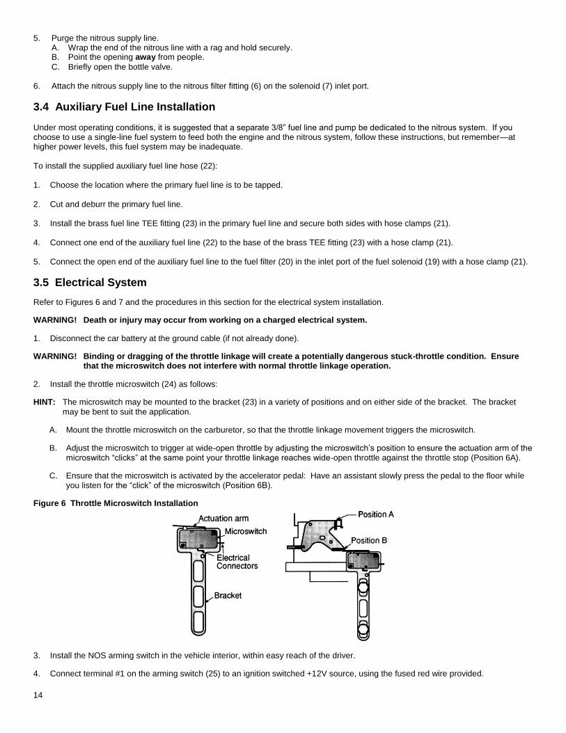
2. Install the throttle microswitch (24) as follows:
HINT: The microswitch may be mounted to the bracket (23) in a variety of positions and on either side of the bracket. The bracket
may be bent to suit the application.
A. Mount the throttle microswitch on the carburetor, so that the throttle linkage movement triggers the microswitch.
B. Adjust the microswitch to trigger at wide-open throttle by adjusting the microswitch’s position to ensure the actuation arm of the microswitch “clicks” at the same point your throttle linkage reaches wide-open throttle against the throttle stop (Position 6A).
C. Ensure that the microswitch is activated by the accelerator pedal: Have an assistant slowly press the pedal to the floor while you listen for the “click” of the microswitch (Position 6B).
Figure 6 Throttle Microswitch Installation
3. Install the NOS arming switch in the vehicle interior, within easy reach of the driver.
4. Connect terminal #1 on the arming switch (25) to an ignition switched +12V source, using the fused red wire provided.
15
NOTE: When selecting an ignition switched +12V source, ensure that your source is capable of handling the amperage of the fuse
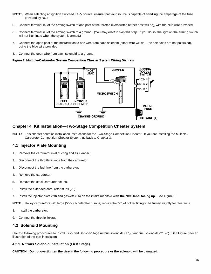
provided by NOS. 5. Connect terminal #2 of the arming switch to one post of the throttle microswitch (either post will do), with the blue wire provided. 6. Connect terminal #3 of the arming switch to a ground. (You may elect to skip this step. If you do so, the light on the arming switch
will not illuminate when the system is armed.) 7. Connect the open post of the microswitch to one wire from each solenoid (either wire will do—the solenoids are not polarized),
using the blue wire provided. 8. Connect the open wire from each solenoid to a ground.
Figure 7 Multiple-Carburetor System Competition Cheater System Wiring Diagram
Chapter 4 Kit Installation—Two-Stage Competition Cheater System NOTE: This chapter contains installation instructions for the Two-Stage Competition Cheater. If you are installing the Multiple-
Carburetor Competition Cheater System, go back to Chapter 3.
4.1 Injector Plate Mounting 1. Remove the carburetor inlet ducting and air cleaner. 2. Disconnect the throttle linkage from the carburetor. 3. Disconnect the fuel line from the carburetor. 4. Remove the carburetor. 5. Remove the stock carburetor studs. 6. Install the extended carburetor studs (29). 7. Install the injector plate (28) and gaskets (16) on the intake manifold with the NOS label facing up. See Figure 8.
NOTE: Holley carburetors with large (50cc) accelerator pumps, require the “Y” jet holder fitting to be turned slightly for clearance.
8. Install the carburetor. 9. Connect the throttle linkage.
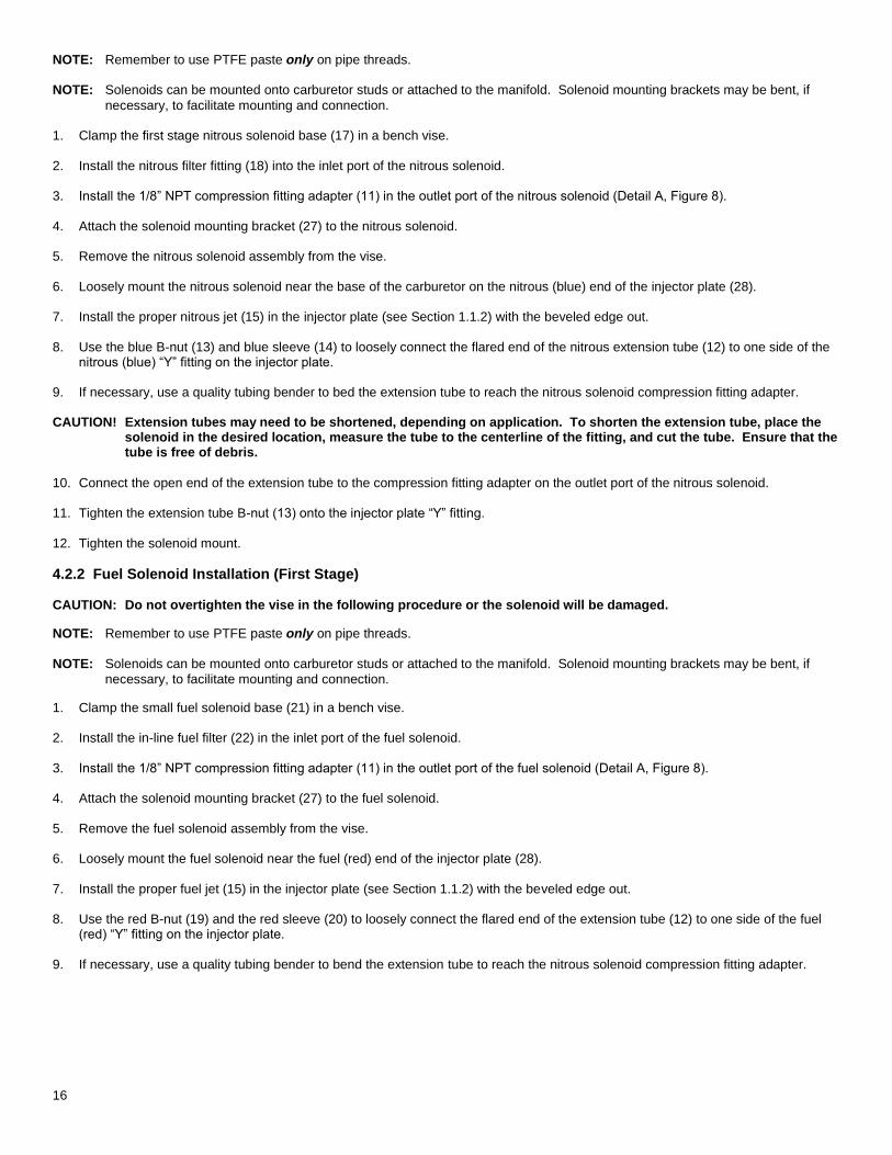
4.2 Solenoid Mounting Use the following procedures to install First- and Second-Stage nitrous solenoids (17,9) and fuel solenoids (21,26). See Figure 8 for an illustration of the part installation.
4.2.1 Nitrous Solenoid Installation (First Stage) CAUTION: Do not overtighten the vise in the following procedure or the solenoid will be damaged.
16
NOTE: Remember to use PTFE paste only on pipe threads.
NOTE: Solenoids can be mounted onto carburetor studs or attached to the manifold. Solenoid mounting brackets may be bent, if
necessary, to facilitate mounting and connection. 1. Clamp the first stage nitrous solenoid base (17) in a bench vise. 2. Install the nitrous filter fitting (18) into the inlet port of the nitrous solenoid. 3. Install the 1/8” NPT compression fitting adapter (11) in the outlet port of the nitrous solenoid (Detail A, Figure 8). 4. Attach the solenoid mounting bracket (27) to the nitrous solenoid. 5. Remove the nitrous solenoid assembly from the vise. 6. Loosely mount the nitrous solenoid near the base of the carburetor on the nitrous (blue) end of the injector plate (28). 7. Install the proper nitrous jet (15) in the injector plate (see Section 1.1.2) with the beveled edge out. 8. Use the blue B-nut (13) and blue sleeve (14) to loosely connect the flared end of the nitrous extension tube (12) to one side of the
nitrous (blue) “Y” fitting on the injector plate. 9. If necessary, use a quality tubing bender to bed the extension tube to reach the nitrous solenoid compression fitting adapter. CAUTION! Extension tubes may need to be shortened, depending on application. To shorten the extension tube, place the
solenoid in the desired location, measure the tube to the centerline of the fitting, and cut the tube. Ensure that the tube is free of debris.
10. Connect the open end of the extension tube to the compression fitting adapter on the outlet port of the nitrous solenoid. 11. Tighten the extension tube B-nut (13) onto the injector plate “Y” fitting. 12. Tighten the solenoid mount.
4.2.2 Fuel Solenoid Installation (First Stage) CAUTION: Do not overtighten the vise in the following procedure or the solenoid will be damaged.
NOTE: Remember to use PTFE paste only on pipe threads.
NOTE: Solenoids can be mounted onto carburetor studs or attached to the manifold. Solenoid mounting brackets may be bent, if
necessary, to facilitate mounting and connection.
1. Clamp the small fuel solenoid base (21) in a bench vise. 2. Install the in-line fuel filter (22) in the inlet port of the fuel solenoid. 3. Install the 1/8” NPT compression fitting adapter (11) in the outlet port of the fuel solenoid (Detail A, Figure 8). 4. Attach the solenoid mounting bracket (27) to the fuel solenoid. 5. Remove the fuel solenoid assembly from the vise. 6. Loosely mount the fuel solenoid near the fuel (red) end of the injector plate (28). 7. Install the proper fuel jet (15) in the injector plate (see Section 1.1.2) with the beveled edge out. 8. Use the red B-nut (19) and the red sleeve (20) to loosely connect the flared end of the extension tube (12) to one side of the fuel
(red) “Y” fitting on the injector plate. 9. If necessary, use a quality tubing bender to bend the extension tube to reach the nitrous solenoid compression fitting adapter.
17
Figure 8 Two-Stage Competition Cheater System Assembly Drawing
CAUTION! Extension tubes may need to be shortened, depending on application. To shorten the extension tube, place the solenoid in the desired location, measure the tube to the centerline of the fitting, and cut the tube. Ensure that the tube is free of debris.
10. Connect the open end of the extension tube to the compression fitting adapter on the outlet port of the fuel solenoid. 11. Tighten the extension tube B-nut (19) onto the injector plate “Y” fitting. 12. Tighten the solenoid mount.
4.2.3 Nitrous Solenoid Installation (Second Stage) CAUTION: Do not overtighten the vise in the following procedure or the solenoid will be damaged.
NOTE: Remember to use PTFE paste only on pipe threads.
NOTE: Solenoids can be mounted onto carburetor studs or attached to the manifold. Solenoid mounting brackets may be bent, if
necessary, to facilitate mounting and connection. 1. Clamp the large nitrous solenoid base (9) in a bench vise.
18
2. Install the nitrous filter (8) into the inlet port of the nitrous solenoid. 3. Install the 1/8” NPT compression fitting adapter (11) in the outlet port of the nitrous solenoid (Detail A, Figure 8). 4. Attach the solenoid mounting bracket (10) to the nitrous solenoid. 5. Remove the nitrous solenoid assembly from the vise. 6. Loosely mount the nitrous solenoid near the base of the carburetor on the nitrous (blue) end of the injector plate (28). 7. Install the proper nitrous jet (15) in the injector plate “Y” fitting (see Section 1.1.2) with the beveled edge out. 8. Use the blue B-nut (13) and the blue sleeve (14) to loosely connect the flared end of the nitrous extension tube (12) to one side of
the nitrous (blue) “Y” fitting on the injector plate. 9. If necessary, use a quality tubing bender to bend the extension tube to reach the nitrous solenoid compression fitting adapter. CAUTION! Extension tubes may need to be shortened, depending on application. To shorten the extension tube, place the
solenoid in the desired location, measure the tube to the centerline of the fitting, and cut the tube. Ensure that the tube is free of debris.
10. Connect the open end of the extension tube to the compression fitting adapter on the outlet port of the nitrous solenoid. 11. Tighten the extension tube B-nut (13) onto the injector plate “Y” fitting. 12. Tighten the solenoid mount.
4.2.4 Fuel Solenoid Installation (Second Stage) CAUTION: Do not overtighten the vise in the following procedure or the solenoid will be damaged. NOTE: Remember to use PTFE paste only on pipe threads.
NOTE: Solenoids can be mounted onto carburetor studs or attached to the manifold. Solenoid mounting brackets may be bent, if
necessary, to facilitate mounting and connection. 1. Clamp the large fuel solenoid base (26) in a bench vise. 2. Install the in-line fuel filter (22) in the inlet port of the fuel solenoid. 3. Install the 1/8” NPT compression fitting adapter (11) in the outlet port of the fuel solenoid (Detail A, Figure 8). 4. Attach the solenoid mounting bracket (10) to the fuel solenoid. 5. Remove the fuel solenoid assembly from the vise. 6. Loosely mount the fuel solenoid near the fuel (red) end of the injector plate (28). 7. Install the proper fuel jet (15) in the injector plate (see Section 1.1.2) with the beveled edge out. 8. Use the red B-nut (19) and the red sleeve (20) to loosely connect the flared end of the extension tube (12) to one side of the fuel
(red) “Y” fitting on the injector plate. 9. If necessary, use a quality tubing bender to bend the extension tube to reach the nitrous solenoid compression fitting adapter. CAUTION! Extension tubes may need to be shortened, depending on application. To shorten the extension tube, place the
solenoid in the desired location, measure the tube to the centerline of the fitting, and cut the tube. Ensure that the tube is free of debris.
10. Connect the open end of the extension tube to the compression fitting adapter on the outlet port of the fuel solenoid. 11. Tighten the extension tube B-nut (19) onto the injector plate “Y” fitting. 12. Tighten the solenoid mount.
19
4.3 Nitrous Feed Line Mounting HINT: Most late-model vehicles have access plugs in the trunk floor, which are convenient for line routing. Following the fuel lines
along the underbody, and entering the engine bay through the front fender well between the plastic inner fender and the body, usually works well.
1. Determine the route for your nitrous feed line to follow. Ensure that the path is clear of exhaust system, suspension, steering, wheels, electrical lines and components, and tires.
2. Feed the main nitrous supply line (5) along the proposed route. 3. If it is necessary to support the nitrous supply line under the vehicle, use 1/2” Tinnerman clamps or nylon tie-wraps to support the
line securely. 4. Attach the nitrous supply line to the nitrous bottle valve adapter (3). WARNING: Nitrous oxide is dangerous to humans if inhaled or comes in contact with the skin. Always point the nitrous line
opening away from people when purging the line.
5. Purge the nitrous supply line.
A. Wrap the end of the nitrous line with a rag and hold securely. B. Point the opening away from people.
C. Briefly open the bottle valve. 6. Attach the nitrous supply line to the base of the 4AN TEE fitting (6). 7. Connect one end of each 1 ft. x 4AN supply line (7) to the open ports of the 4AN TEE fitting (6). 8. Connect the open end of one 4AN supply line (7) to the nitrous filter fitting (18) on the inlet port of the first-stage (small) nitrous
solenoid (17). 9. Connect the open end of the remaining 4AN supply line (7) to the inlet port of the second-stage nitrous solenoid (9). 10. Ensure that all connections are snug.
4.4 Auxiliary Fuel Line Installation Under most operating conditions, it is suggested that a separate 3/8” fuel line and pump be dedicated to the nitrous system. If you choose to use a single-line fuel system to feed both the engine and the nitrous system, follow these instructions, but remember—at higher power levels, this fuel system may be inadequate. To install the supplied auxiliary fuel line (23): 1. Choose the location where the primary fuel line is to be tapped. 2. Cut and deburr the primary fuel line. 3. Install the brass fuel line TEE fitting (24) in the primary fuel line and secure both sides with hose clamps (25). 4. Connect one end of a 3/8” x 2 ft. fuel line (23) to the base of the first brass fuel line TEE fitting (24) with a hose clamp (25). 5. Connect the open end of this 3/8” x 2 ft. fuel line (23) to the base of the second brass fuel line TEE fitting (24) with a hose clamp
(25). 6. Connect one end of each 3/8” x 2 ft. fuel lines (23) to the open ports of the second fuel line TEE fitting (24) with a hose clamp (25). 7. Connect the open end of one 3/8” x 2 ft. fuel line (23) to the fuel filter (22) on the inlet port of the designated first-stage fuel solenoid
(21) with a hose clamp (25). 8. Connect the open end of the remaining 3/8” x 2 ft. fuel line (23) to the fuel filter (22) on the inlet port of the designated second-
stage fuel solenoid (26) with a hose clamp (25).
4.5 Electrical System Installation Refer to Figure 9 and the procedures in this section for the electrical system installation.
WARNING! Death or injury may occur from working on a charged electrical system.
20
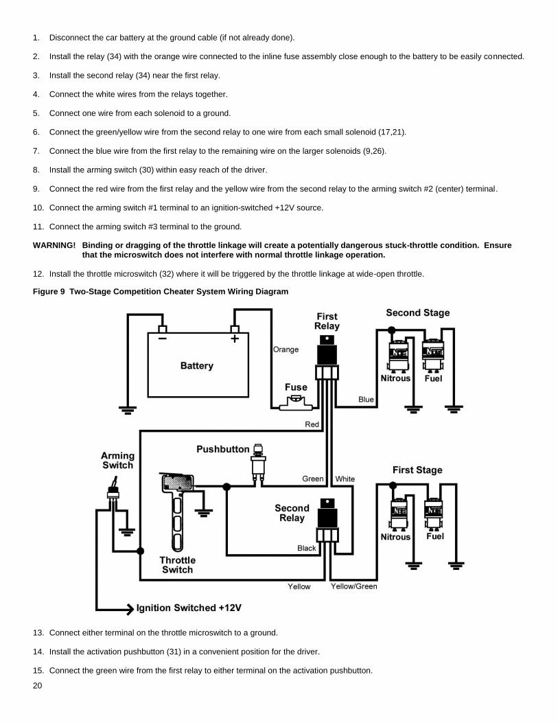
1. Disconnect the car battery at the ground cable (if not already done). 2. Install the relay (34) with the orange wire connected to the inline fuse assembly close enough to the battery to be easily connected. 3. Install the second relay (34) near the first relay. 4. Connect the white wires from the relays together. 5. Connect one wire from each solenoid to a ground. 6. Connect the green/yellow wire from the second relay to one wire from each small solenoid (17,21). 7. Connect the blue wire from the first relay to the remaining wire on the larger solenoids (9,26). 8. Install the arming switch (30) within easy reach of the driver. 9. Connect the red wire from the first relay and the yellow wire from the second relay to the arming switch #2 (center) terminal. 10. Connect the arming switch #1 terminal to an ignition-switched +12V source. 11. Connect the arming switch #3 terminal to the ground. WARNING! Binding or dragging of the throttle linkage will create a potentially dangerous stuck-throttle condition. Ensure
that the microswitch does not interfere with normal throttle linkage operation.
12. Install the throttle microswitch (32) where it will be triggered by the throttle linkage at wide-open throttle.
Figure 9 Two-Stage Competition Cheater System Wiring Diagram
13. Connect either terminal on the throttle microswitch to a ground. 14. Install the activation pushbutton (31) in a convenient position for the driver. 15. Connect the green wire from the first relay to either terminal on the activation pushbutton.
21
16. Connect the remaining activation pushbutton terminal and the black wire from the second relay to the open terminal on the throttle
microswitch. 17. Connect the open lead from the in-line fuse assembly to the battery positive (+) terminal. 18. Reconnect the battery. HINT: If the arming switch has been connected to a +12V ignition-switched source, nothing will work if the key is off, regardless of the
arming switch position. Neither system can operate if the arming switch is off.
4.6 Electrical System Checkout 1. Ensure that the nitrous bottle valve is closed and the fuel pump(s) is off. 2. Turn the arming switch off. 3. Press and hold the throttle full open. The first-stage solenoids should click. 4. Press and hold the activation pushbutton. The second-stage solenoids should click. 5. Release the activation pushbutton. The first-stage solenoid should click again. 6. Release the throttle.
Chapter 5 Preparing for Operation
5.1 Checkout Procedure—Multiple-Carburetor Competition Cheater System After you have completed the installation of your NOS Multiple-Carburetor Competition Cheater System kit, perform the following checkout procedure before operating your vehicle. NOTE: Before performing steps 1-4, make sure that the nitrous bottle valve is closed and the main nitrous supply line is empty.
1. Close the N2O bottle valve. Empty the main N2O feed line. 2. Turn on the fuel pump.
3. Check all the fuel lines and fittings for leaks.
4. Start the engine. 5. Turn the arming switch on. 6. Set the engine speed at 2000 rpm.
7. Briefly depress the activation arm on the microswitch. The engine speed should decrease if the fuel delivery system is performing properly. If it is not, refer to Appendix A, Troubleshooting Guide.
8. Open the nitrous bottle valve.
NOTE: There should be no change in the engine idle speed. If the idle speed changes, refer to Appendix A, Troubleshooting Guide.
9. Inspect the nitrous lines and fittings for leaks.
10. ENJOY!
5.2 Checkout Procedure—Two-Stage Competition Cheater System After you have completed the installation of your NOS Multiple-Carburetor Competition Cheater System kit, perform the following checkout procedure before operating your vehicle. NOTE: Before performing steps 1-4, make sure that the nitrous bottle valve is closed and the main nitrous supply line is empty.
1. Turn on the fuel pump.
22
2. Check all the fuel lines and fittings for leaks. 3. Start the engine. 4. Turn the arming switch on. 5. First-Stage check: With the N2O bottle valve closed and the N2O main feed line empty:
A. Set the engine speed at 2000 rpm. B. Have an assistant briefly activate (press and release) the microswitch. C. The engine speed should decrease, if the fuel delivery system is performing properly. D. If the engine speed does not decrease, refer to Appendix A, Troubleshooting Guide.
6. Second-Stage check: With the N2O bottle valve closed and the N2O main feed line empty:
A. Disconnect the yellow/green wire from the small fuel solenoid (21). B. Set the engine speed at 2000 rpm. C. Have an assistant briefly activate (press and release) the microswitch. D. Briefly activate the pushbutton. E. The engine speed should decrease, if the fuel delivery system is performing properly. F. If the engine speed does not decrease, refer to Appendix A, Troubleshooting Guide. G. Connect the yellow/green wire to the small fuel solenoid (21).
7. Open the nitrous bottle valve. 8. Inspect the nitrous lines and fittings for leaks. 9. ENJOY!
Chapter 6 Tuning Suggestions
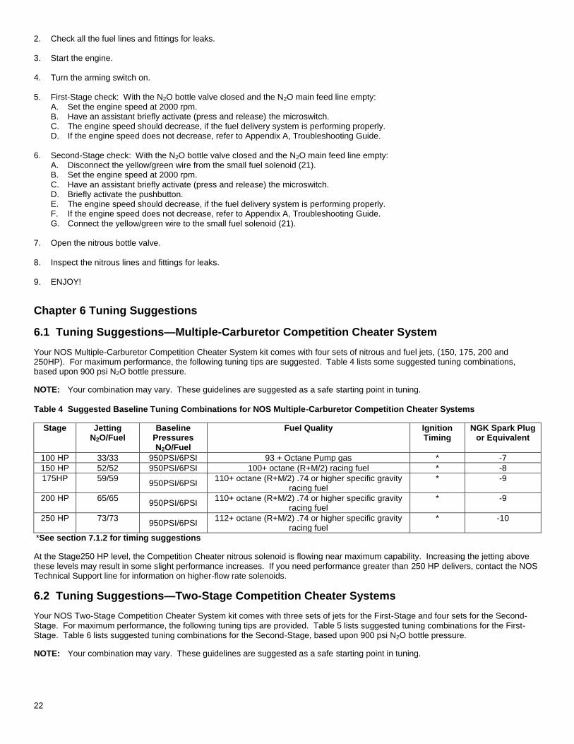
6.1 Tuning Suggestions—Multiple-Carburetor Competition Cheater System
Your NOS Multiple-Carburetor Competition Cheater System kit comes with four sets of nitrous and fuel jets, (150, 175, 200 and 250HP). For maximum performance, the following tuning tips are suggested. Table 4 lists some suggested tuning combinations, based upon 900 psi N2O bottle pressure.
NOTE: Your combination may vary. These guidelines are suggested as a safe starting point in tuning. Table 4 Suggested Baseline Tuning Combinations for NOS Multiple-Carburetor Competition Cheater Systems
Stage Jetting N2O/Fuel
Baseline Pressures N2O/Fuel
Fuel Quality Ignition Timing
NGK Spark Plug or Equivalent
100 HP 33/33 950PSI/6PSI 93 + Octane Pump gas * -7
150 HP 52/52 950PSI/6PSI 100+ octane (R+M/2) racing fuel * -8
175HP 59/59 950PSI/6PSI
110+ octane (R+M/2) .74 or higher specific gravity racing fuel
* -9
200 HP 65/65 950PSI/6PSI
110+ octane (R+M/2) .74 or higher specific gravity racing fuel
* -9
250 HP 73/73 950PSI/6PSI
112+ octane (R+M/2) .74 or higher specific gravity racing fuel
* -10
*See section 7.1.2 for timing suggestions
At the Stage250 HP level, the Competition Cheater nitrous solenoid is flowing near maximum capability. Increasing the jetting above these levels may result in some slight performance increases. If you need performance greater than 250 HP delivers, contact the NOS Technical Support line for information on higher-flow rate solenoids.
6.2 Tuning Suggestions—Two-Stage Competition Cheater Systems
Your NOS Two-Stage Competition Cheater System kit comes with three sets of jets for the First-Stage and four sets for the Second-Stage. For maximum performance, the following tuning tips are provided. Table 5 lists suggested tuning combinations for the First-Stage. Table 6 lists suggested tuning combinations for the Second-Stage, based upon 900 psi N2O bottle pressure.
NOTE: Your combination may vary. These guidelines are suggested as a safe starting point in tuning.
23
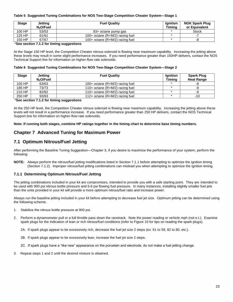
Table 5 Suggested Tuning Combinations for NOS Two-Stage Competition Cheater System—Stage 1
Stage Jetting N2O/Fuel
Fuel Quality Ignition Timing
NGK Spark Plug or Equivalent
100 HP 53/53 93+ octane pump gas * Stock
125 HP 61/61 100+ octane (R+M/2) racing fuel * -7
150 HP 67/67 100+ octane (R+M/2) racing fuel * -8
*See section 7.1.2 for timing suggestions
At the Stage 150 HP level, the Competition Cheater nitrous solenoid is flowing near maximum capability. Increasing the jetting above these levels may result in some slight performance increases. If you need performance greater than 150HP delivers, contact the NOS Technical Support line for information on higher-flow rate solenoids. Table 6 Suggested Tuning Combinations for NOS Two-Stage Competition Cheater System—Stage 2
Stage Jetting N2O/Fuel
Fuel Quality Ignition Timing
Spark Plug Heat Range
150 HP 63/63 100+ octane (R+M/2) racing fuel * -8
185 HP 73/73 110+ octane (R+M/2) racing fuel * -9
210 HP 82/82 110+ octane (R+M/2) racing fuel * -9
250 HP 93/93 112+ octane (R+M/2) racing fuel * -10
*See section 7.1.2 for timing suggestions
At the 250 HP level, the Competition Cheater nitrous solenoid is flowing near maximum capability. Increasing the jetting above these levels will not result in a performance increase. If you need performance greater than 250 HP delivers, contact the NOS Technical Support line for information on higher-flow rate solenoids. Note: If running both stages, combine HP ratings together in the timing chart to determine base timing numbers.
Chapter 7 Advanced Tuning for Maximum Power
7.1 Optimum Nitrous/Fuel Jetting After performing the Baseline Tuning Suggestion—Chapter 3, if you desire to maximize the performance of your system, perform the following: NOTE: Always perform the nitrous/fuel jetting modifications listed in Section 7.1.1 before attempting to optimize the ignition timing
(Section 7.1.2). Improper nitrous/fuel jetting combinations can mislead you when attempting to optimize the ignition timing.
7.1.1 Determining Optimum Nitrous/Fuel Jetting The jetting combinations included in your kit are compromises, intended to provide you with a safe starting point. They are intended to be used with 900 psi nitrous bottle pressure and 5-6 psi flowing fuel pressure. In many instances, installing slightly smaller fuel jets than the units provided in your kit will provide a more optimum nitrous/fuel ratio and increase power. Always run the baseline jetting included in your kit before attempting to decrease fuel jet size. Optimum jetting can be determined using the following scheme. 1. Stabilize the nitrous bottle pressure at 900 psi. 2. Perform a dynamometer pull or a full throttle pass down the racetrack. Note the power reading or vehicle mph (not e.t.). Examine
spark plugs for the indication of lean or rich nitrous/fuel conditions (refer to Figure 10 for tips on reading the spark plugs).
2A. If spark plugs appear to be excessively rich, decrease the fuel jet size 2 steps (ex. 61 to 59, 82 to 80, etc;).
2B. If spark plugs appear to be excessively lean, increase the fuel jet size 2 steps. 2C. If spark plugs have a “like new” appearance on the porcelain and electrode, do not make a fuel jetting change.
3. Repeat steps 1 and 2 until the desired mixture is obtained.
24
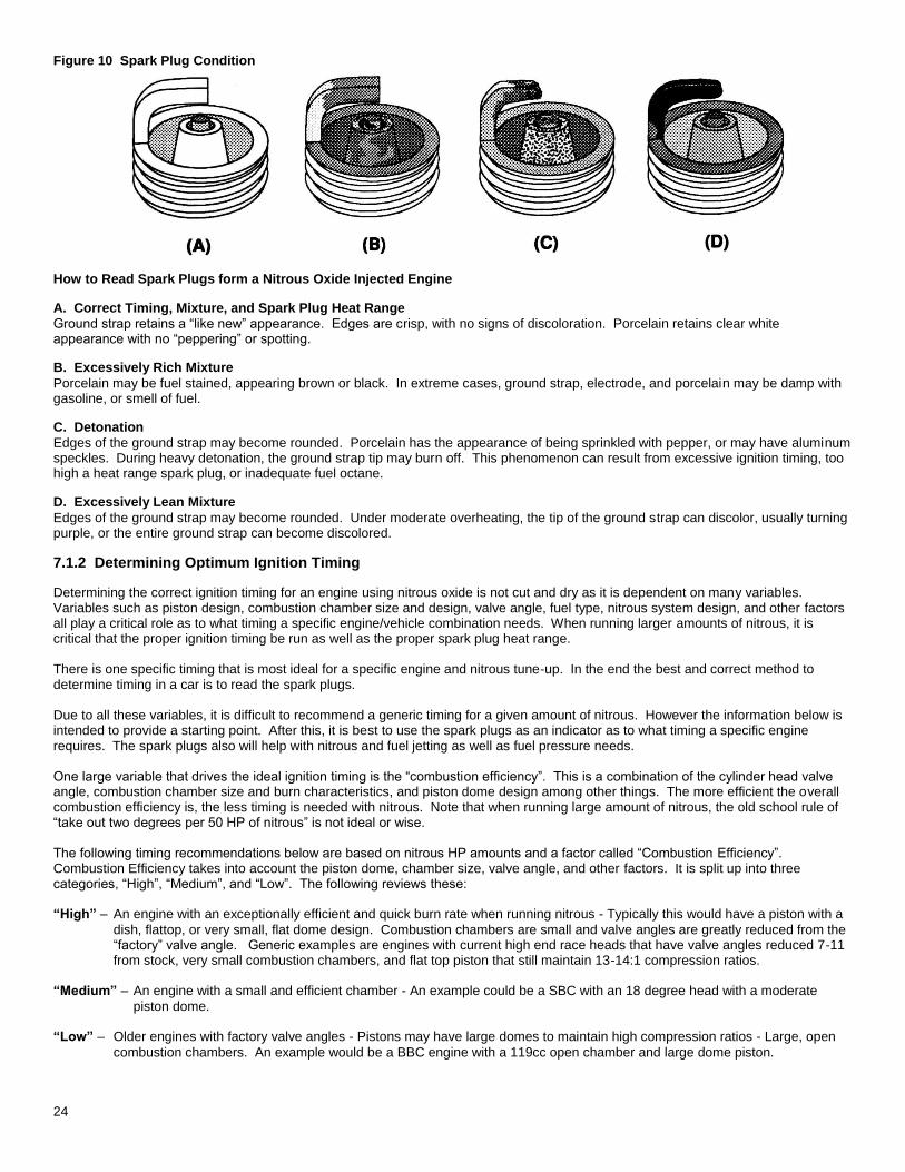
Figure 10 Spark Plug Condition
How to Read Spark Plugs form a Nitrous Oxide Injected Engine
A. Correct Timing, Mixture, and Spark Plug Heat Range
Ground strap retains a “like new” appearance. Edges are crisp, with no signs of discoloration. Porcelain retains clear white appearance with no “peppering” or spotting.
B. Excessively Rich Mixture
Porcelain may be fuel stained, appearing brown or black. In extreme cases, ground strap, electrode, and porcelain may be damp with gasoline, or smell of fuel.
C. Detonation
Edges of the ground strap may become rounded. Porcelain has the appearance of being sprinkled with pepper, or may have aluminum speckles. During heavy detonation, the ground strap tip may burn off. This phenomenon can result from excessive ignition timing, too high a heat range spark plug, or inadequate fuel octane.
D. Excessively Lean Mixture
Edges of the ground strap may become rounded. Under moderate overheating, the tip of the ground strap can discolor, usually turning purple, or the entire ground strap can become discolored.
7.1.2 Determining Optimum Ignition Timing
Determining the correct ignition timing for an engine using nitrous oxide is not cut and dry as it is dependent on many variables. Variables such as piston design, combustion chamber size and design, valve angle, fuel type, nitrous system design, and other factors all play a critical role as to what timing a specific engine/vehicle combination needs. When running larger amounts of nitrous, it is critical that the proper ignition timing be run as well as the proper spark plug heat range. There is one specific timing that is most ideal for a specific engine and nitrous tune-up. In the end the best and correct method to determine timing in a car is to read the spark plugs. Due to all these variables, it is difficult to recommend a generic timing for a given amount of nitrous. However the information below is intended to provide a starting point. After this, it is best to use the spark plugs as an indicator as to what timing a specific engine requires. The spark plugs also will help with nitrous and fuel jetting as well as fuel pressure needs. One large variable that drives the ideal ignition timing is the “combustion efficiency”. This is a combination of the cylinder head valve angle, combustion chamber size and burn characteristics, and piston dome design among other things. The more efficient the overall combustion efficiency is, the less timing is needed with nitrous. Note that when running large amount of nitrous, the old school rule of “take out two degrees per 50 HP of nitrous” is not ideal or wise. The following timing recommendations below are based on nitrous HP amounts and a factor called “Combustion Efficiency”. Combustion Efficiency takes into account the piston dome, chamber size, valve angle, and other factors. It is split up into three categories, “High”, “Medium”, and “Low”. The following reviews these: “High” – An engine with an exceptionally efficient and quick burn rate when running nitrous - Typically this would have a piston with a
dish, flattop, or very small, flat dome design. Combustion chambers are small and valve angles are greatly reduced from the “factory” valve angle. Generic examples are engines with current high end race heads that have valve angles reduced 7-11 from stock, very small combustion chambers, and flat top piston that still maintain 13-14:1 compression ratios.
“Medium” – An engine with a small and efficient chamber - An example could be a SBC with an 18 degree head with a moderate
piston dome. “Low” – Older engines with factory valve angles - Pistons may have large domes to maintain high compression ratios - Large, open
combustion chambers. An example would be a BBC engine with a 119cc open chamber and large dome piston.
25
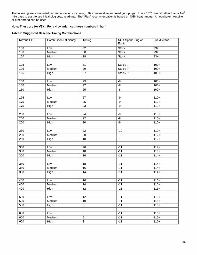
The following are some initial recommendations for timing. Be conservative and read your plugs. Run a 1/8th
mile hit rather than a 1/4th
mile pass to start to see initial plug strap readings. The “Plug” recommendation is based on NGK heat ranges. An equivalent Autolite or other brand can be used. Note: These are for V8’s. For a 4 cylinder, cut these numbers in half.
Table 7 Suggested Baseline Timing Combinations
Nitrous HP Combustion Efficiency Timing NGK Spark Plug or Equiv.
Fuel/Octane
100 Low 32 Stock 93+
100 Medium 30 Stock 93+
100 High 28 Stock 93+
125 Low 31 Stock/-7 100+
125 Medium 29 Stock/-7 100+
125 High 27 Stock/-7 100+
150 Low 29 -8 100+
150 Medium 27 -8 100+
150 High 25 -8 100+
175 Low 27 -9 110+
175 Medium 25 -9 110+
175 High 23 -9 110+
200 Low 24 -9 110+
200 Medium 22 -9 110+
200 High 20 -9 110+
250 Low 22 -10 112+
250 Medium 20 -10 112+
250 High 18 -10 112+
300 Low 20 -11 114+
300 Medium 18 -11 114+
300 High 16 -11 114+
350 Low 18 -11 114+
350 Medium 16 -11 114+
350 High 14 -11 114+
400 Low 16 -11 116+
400 Medium 14 -11 116+
400 High 12 -11 116+
500 Low 12 -11 116+
500 Medium 10 -11 116+
500 High 8 -11 116+
600 Low 8 -11 116+
600 Medium 6 -11 116+
600 High 2 -11 116+
26
Chapter 8 Routine Maintenance
8.1 Nitrous Solenoid Filter
When nitrous bottles are refilled they can become contaminated with debris, if the refiller does not have an adequate filter in his transfer pump mechanism. Contaminants in the bottle will eventually become lodged in the nitrous solenoid filter fitting. You should periodically (after every 20-30 pounds of nitrous usage) examine the mesh in the nitrous filter for debris. To clean the filter, follow the following steps: 1. Close the valve on the nitrous bottle. 2. Empty the main nitrous feed line. 3. Disconnect the main nitrous feed line from the nitrous solenoid. 4. Remove the nitrous filter fitting from the nitrous solenoid. 5. Remove all PTFE paste debris from the solenoid inlet port threads and from the nitrous solenoid filter pipe threads.
6. Examine the mesh in the nitrous filter fitting for contaminants. Blow out debris with compressed air, if necessary. 7. Apply fresh PTFE paste to the nitrous filter pipe threads. Reinstall the filter in the nitrous solenoid. 8. Reconnect the main nitrous supply line to the nitrous solenoid.
8.2 Nitrous Solenoid Plunger 8.2.1 General Information The seals used in NOS nitrous solenoid plungers are constructed from materials that are designed to be used with nitrous oxide. When kept free from fuel contaminants or from over-pressurization, they should provide trouble free performance. You should periodically (after every 20-30 pounds of nitrous usage) examine the seal in the nitrous solenoid plunger. Due to the Competition Cheater System kit being a wet manifold style nitrous kit, the nitrous solenoid plunger will get exposed to fuel vapors. This is unavoidable. Fluctuations in the intake manifold pressure due to opening and closing of the throttle induce flow into the out of the NOS injector plate spray bars (fuel and nitrous), when the NOS system is not in use. Long term exposure of the nitrous solenoid plunger seal to the fuel vapors will result in swelling of the plunger seal. This will reduce the nitrous flow (causing an excessively rich nitrous/fuel condition and a loss of power). The seals used in NOS nitrous solenoid plungers are designed to work at pressures up to 1100 psi. Exposing the plunger to excessive pressure (whether the vehicle is sitting or in-use) can result in the seal in the plunger swelling or in extreme cases disintegrating. NOTE: The seals are designed so that if they fail due to over-pressurization, they will not leak, the valve will just fail to flow nitrous
oxide. Swelling of the nitrous solenoid plunger seal will reduce nitrous flow (causing an excessively rich nitrous/fuel condition and a loss of power).
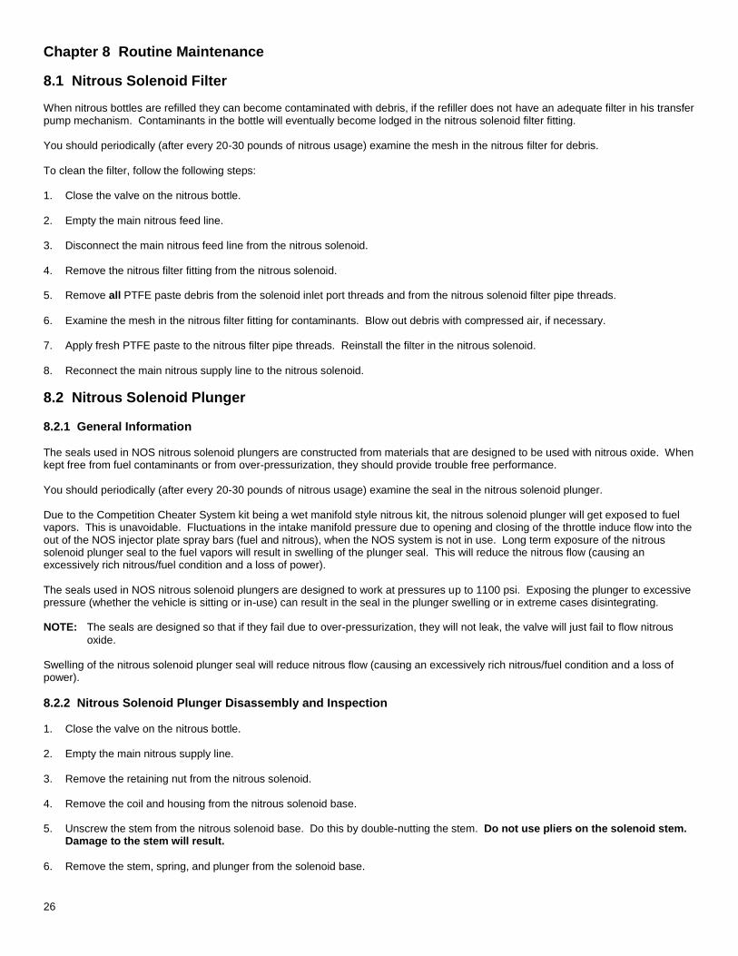
8.2.2 Nitrous Solenoid Plunger Disassembly and Inspection 1. Close the valve on the nitrous bottle. 2. Empty the main nitrous supply line. 3. Remove the retaining nut from the nitrous solenoid. 4. Remove the coil and housing from the nitrous solenoid base. 5. Unscrew the stem from the nitrous solenoid base. Do this by double-nutting the stem. Do not use pliers on the solenoid stem.
Damage to the stem will result.
6. Remove the stem, spring, and plunger from the solenoid base.
27
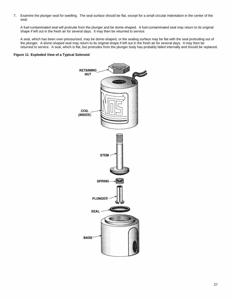
7. Examine the plunger seal for swelling. The seal surface should be flat, except for a small circular indentation in the center of the seal;
A fuel-contaminated seal will protrude from the plunger and be dome-shaped. A fuel-contaminated seal may return to its original shape if left out in the fresh air for several days. It may then be returned to service.
A seal, which has been over-pressurized, may be dome-shaped, or the sealing surface may be flat with the seal protruding out of the plunger. A dome-shaped seal may return to its original shape if left out in the fresh air for several days. It may then be returned to service. A seal, which is flat, but protrudes from the plunger body has probably failed internally and should be replaced.
Figure 11 Exploded View of a Typical Solenoid
28
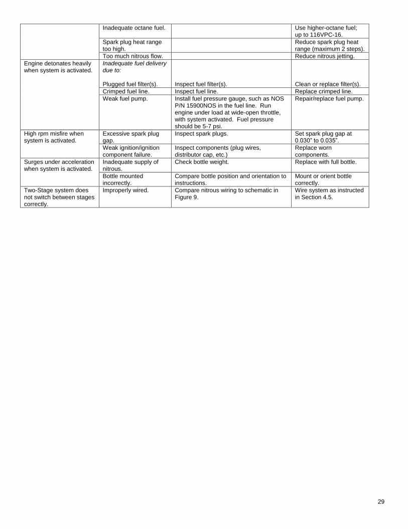
Appendix A Troubleshooting Guide
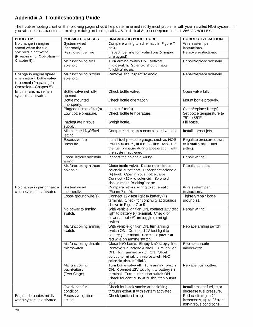
The troubleshooting chart on the following pages should help determine and rectify most problems with your installed NOS system. If you still need assistance determining or fixing problems, call NOS Technical Support Department at 1-866-GOHOLLEY.
PROBLEM POSSIBLE CAUSES DIAGNOSTIC PROCEDURE CORRECTIVE ACTION
No change in engine speed when the fuel solenoid is activated (Preparing for Operation—Chapter 5).
System wired incorrectly.
Compare wiring to schematic in Figure 7 or 9.
Wire system per instructions.
Restricted fuel line. Inspect fuel line for restrictions (crimped or plugged).
Remove restrictions.
Malfunctioning fuel solenoid.
Turn arming switch ON. Activate microswitch. Solenoid should make “clicking” noise.
Repair/replace solenoid.
Change in engine speed when nitrous bottle valve is opened (Preparing for Operation—Chapter 5).
Malfunctioning nitrous solenoid.
Remove and inspect solenoid. Repair/replace solenoid.
Engine runs rich when system is activated.
Bottle valve not fully opened.
Check bottle valve. Open valve fully.
Bottle mounted improperly.
Check bottle orientation. Mount bottle properly.
Plugged nitrous filter(s). Inspect filter(s). Clean/replace filter(s).
Low bottle pressure. Check bottle temperature. Set bottle temperature to 75° to 85°F.
Inadequate nitrous supply.
Weigh bottle. Fill bottle.
Mismatched N2O/fuel jetting.
Compare jetting to recommended values. Install correct jets.
Excessive fuel pressure.
Install fuel pressure gauge, such as NOS P/N 15900NOS, in the fuel line. Measure the fuel pressure during acceleration, with the system activated.
Regulate pressure down, or install smaller fuel jetting.
Loose nitrous solenoid wiring.
Inspect the solenoid wiring. Repair wiring.
Malfunctioning nitrous solenoid.
Close bottle valve. Disconnect nitrous solenoid outlet port. Disconnect solenoid (+) lead. Open nitrous bottle valve. Connect +12V to solenoid. Solenoid should make “clicking” noise.
Rebuild solenoid.
No change in performance when system is activated.
System wired incorrectly.
Compare nitrous wiring to schematic (Figure 7 or 9).
Wire system per instructions.
Loose ground wire(s). Connect 12V test light to battery (+) terminal. Check for continuity at grounds shown in Figure 7 or 9.
Tighten/repair loose ground(s).
No power to arming switch.
With vehicle ignition ON, connect 12V test light to battery (-) terminal. Check for power at pole #1 on toggle (arming) switch.
Repair wiring.
Malfunctioning arming switch.
With vehicle ignition ON, turn arming switch ON. Connect 12V test light to battery (-) terminal. Check for power at red wire on arming switch.
Replace arming switch.
Malfunctioning throttle microswitch.
Close N2O bottle. Empty N2O supply line. Remove fuel solenoid shell. Turn ignition ON. Turn arming switch ON. Short across terminals on microswitch, N2O solenoid should “click”.
Replace throttle microswitch.
Malfunctioning pushbutton. (Two-Stage)
Turn bottle valve off. Turn arming switch ON. Connect 12V test light to battery (-) terminal. Turn pushbutton switch ON. Check for continuity at pushbutton output pole.
Replace pushbutton.
Overly rich fuel condition.
Check for black smoke or backfiring through exhaust with system activated.
Install smaller fuel jet or decrease fuel pressure.
Engine detonates mildly when system is activated.
Excessive ignition timing.
Check ignition timing. Reduce timing in 2° increments, up to 8° from non-nitrous conditions.
29
Inadequate octane fuel. Use higher-octane fuel; up to 116VPC-16.
Spark plug heat range too high.
Reduce spark plug heat range (maximum 2 steps).
Too much nitrous flow. Reduce nitrous jetting.
Engine detonates heavily when system is activated.
Inadequate fuel delivery due to: Plugged fuel filter(s).
Inspect fuel filter(s).
Clean or replace filter(s).
Crimped fuel line. Inspect fuel line. Replace crimped line.
Weak fuel pump. Install fuel pressure gauge, such as NOS P/N 15900NOS in the fuel line. Run engine under load at wide-open throttle, with system activated. Fuel pressure should be 5-7 psi.
Repair/replace fuel pump.
High rpm misfire when system is activated.
Excessive spark plug gap.
Inspect spark plugs. Set spark plug gap at 0.030” to 0.035”.
Weak ignition/ignition component failure.
Inspect components (plug wires, distributor cap, etc.)
Replace worn components.
Surges under acceleration when system is activated.
Inadequate supply of nitrous.
Check bottle weight. Replace with full bottle.
Bottle mounted incorrectly.
Compare bottle position and orientation to instructions.
Mount or orient bottle correctly.
Two-Stage system does not switch between stages correctly.
Improperly wired. Compare nitrous wiring to schematic in Figure 9.
Wire system as instructed in Section 4.5.
30
Nitrous Oxide Accessories
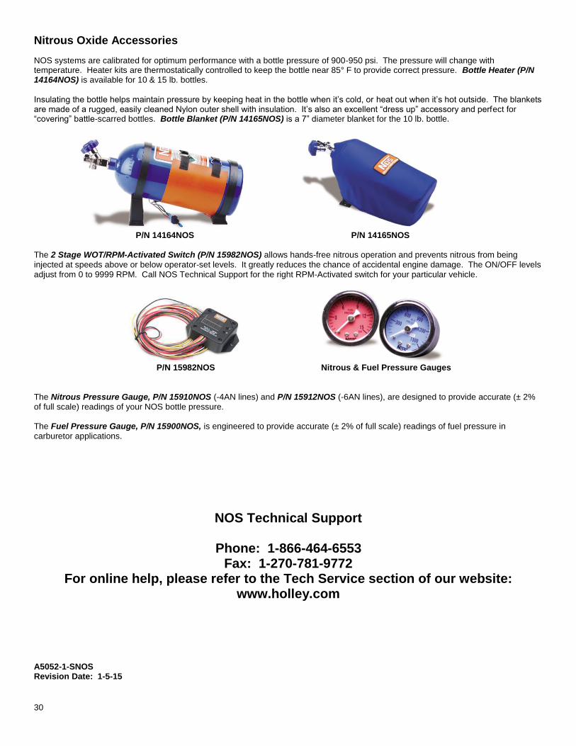
NOS systems are calibrated for optimum performance with a bottle pressure of 900-950 psi. The pressure will change with temperature. Heater kits are thermostatically controlled to keep the bottle near 85° F to provide correct pressure. Bottle Heater (P/N 14164NOS) is available for 10 & 15 lb. bottles. Insulating the bottle helps maintain pressure by keeping heat in the bottle when it’s cold, or heat out when it’s hot outside. The blankets are made of a rugged, easily cleaned Nylon outer shell with insulation. It’s also an excellent “dress up” accessory and perfect for “covering” battle-scarred bottles. Bottle Blanket (P/N 14165NOS) is a 7” diameter blanket for the 10 lb. bottle.
P/N 14164NOS P/N 14165NOS
The 2 Stage WOT/RPM-Activated Switch (P/N 15982NOS) allows hands-free nitrous operation and prevents nitrous from being injected at speeds above or below operator-set levels. It greatly reduces the chance of accidental engine damage. The ON/OFF levels adjust from 0 to 9999 RPM. Call NOS Technical Support for the right RPM-Activated switch for your particular vehicle.
P/N 15982NOS Nitrous & Fuel Pressure Gauges
The Nitrous Pressure Gauge, P/N 15910NOS (-4AN lines) and P/N 15912NOS (-6AN lines), are designed to provide accurate (± 2% of full scale) readings of your NOS bottle pressure. The Fuel Pressure Gauge, P/N 15900NOS, is engineered to provide accurate (± 2% of full scale) readings of fuel pressure in carburetor applications.
NOS Technical Support
Phone: 1-866-464-6553 Fax: 1-270-781-9772
For online help, please refer to the Tech Service section of our website: www.holley.com
A5052-1-SNOS Revision Date: 1-5-15