two lens electron column user’s guideuhv.cheme.cmu.edu/manuals/2leug_b.book.pdf · operating the...
TRANSCRIPT

Two Lens Electron ColumnUser’s Guide
PN 18484-BX

Trademark AcknowledgmentsFEI and the FEI logo are trademarks of FEI Company.
FrameMaker is a registered trademark of Adobe Systems Incorporated.Other product and company names mentioned herein may be the trademarks of their respective owners.
Production AcknowledgmentsThis guide was produced using FrameMaker® document publishing software
and the Book Antiqua and Arial families of typefaces.
Principal ContributorsKristi O’GormanKathy Spencer
Technical Publications TeamJudy Lane Green
Susan “Dash” GilpinAndy KubrinRoger HoldenErin SunaharaWyn Bowler
email: [email protected]
Copyright © 2001 by FEI Company
Printer: Revolution Publishing
P N 1 8 4 8 4 - B X � 1 0 / 2 6 / 0 1
Two Lens Electron ColumnUser’s Guide
Chapter 1 System OverviewIntroduction . . . . . . . . . . . . . . . . . . . . . . . . . . . . . . . . . . . . . . . . . . . . . . . . . 1-1
Chapter 2 Safety and HandlingFocusing Column . . . . . . . . . . . . . . . . . . . . . . . . . . . . . . . . . . . . . . . . . . . . 2-1Terms and Symbols . . . . . . . . . . . . . . . . . . . . . . . . . . . . . . . . . . . . . . . . . . . 2-3Operation, Maintenance, and Service . . . . . . . . . . . . . . . . . . . . . . . . . . . . 2-4Voltages . . . . . . . . . . . . . . . . . . . . . . . . . . . . . . . . . . . . . . . . . . . . . . . . . . . . . 2-5Chemicals . . . . . . . . . . . . . . . . . . . . . . . . . . . . . . . . . . . . . . . . . . . . . . . . . . . 2-7Miscellaneous Precautions . . . . . . . . . . . . . . . . . . . . . . . . . . . . . . . . . . . . . 2-8
Chapter 3 Hardware and TheoryOverview . . . . . . . . . . . . . . . . . . . . . . . . . . . . . . . . . . . . . . . . . . . . . . . . . . . 3-1External Column Features . . . . . . . . . . . . . . . . . . . . . . . . . . . . . . . . . . . . . 3-2Internal Column Features . . . . . . . . . . . . . . . . . . . . . . . . . . . . . . . . . . . . . 3-4Electronics . . . . . . . . . . . . . . . . . . . . . . . . . . . . . . . . . . . . . . . . . . . . . . . . . . 3-13
Chapter 4 Scanning System InstallationOverview . . . . . . . . . . . . . . . . . . . . . . . . . . . . . . . . . . . . . . . . . . . . . . . . . . . 4-1Preinstallation Preparation . . . . . . . . . . . . . . . . . . . . . . . . . . . . . . . . . . . . . 4-2Installing the Focusing Column. . . . . . . . . . . . . . . . . . . . . . . . . . . . . . . . . 4-3Installing the Ion Getter Pump. . . . . . . . . . . . . . . . . . . . . . . . . . . . . . . . . . 4-4Grounding Protocol . . . . . . . . . . . . . . . . . . . . . . . . . . . . . . . . . . . . . . . . . . . 4-5Installing the High Voltage Power Supply . . . . . . . . . . . . . . . . . . . . . . . 4-6Installing the Digital Deflection Controller . . . . . . . . . . . . . . . . . . . . . . . 4-8Installing a Picoammeter . . . . . . . . . . . . . . . . . . . . . . . . . . . . . . . . . . . . . . 4-8Connecting AC Power. . . . . . . . . . . . . . . . . . . . . . . . . . . . . . . . . . . . . . . . . 4-9Final Preparation . . . . . . . . . . . . . . . . . . . . . . . . . . . . . . . . . . . . . . . . . . . . 4-10
Chapter 5 Column OperationOverview . . . . . . . . . . . . . . . . . . . . . . . . . . . . . . . . . . . . . . . . . . . . . . . . . . . 5-1Column Startup Checklist . . . . . . . . . . . . . . . . . . . . . . . . . . . . . . . . . . . . . 5-2Operating the Thermal Field Emitter . . . . . . . . . . . . . . . . . . . . . . . . . . . . 5-2High Voltage Conditioning . . . . . . . . . . . . . . . . . . . . . . . . . . . . . . . . . . . . 5-5Initial Turn On . . . . . . . . . . . . . . . . . . . . . . . . . . . . . . . . . . . . . . . . . . . . . . . 5-8Aligning the Column. . . . . . . . . . . . . . . . . . . . . . . . . . . . . . . . . . . . . . . . . 5-10Changing Aperture Size . . . . . . . . . . . . . . . . . . . . . . . . . . . . . . . . . . . . . . 5-20Tips for Column Operation . . . . . . . . . . . . . . . . . . . . . . . . . . . . . . . . . . . 5-21Full Power Down . . . . . . . . . . . . . . . . . . . . . . . . . . . . . . . . . . . . . . . . . . . 5-22Operating Parameters . . . . . . . . . . . . . . . . . . . . . . . . . . . . . . . . . . . . . . . . 5-23
P N 1 8 4 8 4 - B X � 1 0 / 2 6 / 0 1
Chapter 6 User MaintenanceOverview . . . . . . . . . . . . . . . . . . . . . . . . . . . . . . . . . . . . . . . . . . . . . . . . . . . 6-1Preparing for Maintenance . . . . . . . . . . . . . . . . . . . . . . . . . . . . . . . . . . . . 6-1Gasket and O-Ring Replacement. . . . . . . . . . . . . . . . . . . . . . . . . . . . . . . . 6-3TFE Replacement . . . . . . . . . . . . . . . . . . . . . . . . . . . . . . . . . . . . . . . . . . . . 6-5Replacing the CIV O-Ring . . . . . . . . . . . . . . . . . . . . . . . . . . . . . . . . . . . . 6-12
Chapter 7 TroubleshootingOverview . . . . . . . . . . . . . . . . . . . . . . . . . . . . . . . . . . . . . . . . . . . . . . . . . . . 7-1Electronics . . . . . . . . . . . . . . . . . . . . . . . . . . . . . . . . . . . . . . . . . . . . . . . . . . 7-1Image . . . . . . . . . . . . . . . . . . . . . . . . . . . . . . . . . . . . . . . . . . . . . . . . . . . . . . 7-2Vacuum . . . . . . . . . . . . . . . . . . . . . . . . . . . . . . . . . . . . . . . . . . . . . . . . . . . . . 7-5
Appendix ATechnical Articles . . . . . . . . . . . . . . . . . . . . . . . . . . . . . . . . . . . . . . . . . . . A-1
Glossary
Index

1-1P N 1 8 4 8 4 - B X � 1 0 / 2 6 / 0 1
1System Overview
Introduction
Two Lens Electron ColumnFEI's™ Two Lens Electron (2LE) Column is designed for use in an ultra-high vacuum (UHV) environment and for providing bolt-on scanning electron microscope (SEM) capabilities to an existing system.
The 2LE column achieves high-resolution imaging capability, maximum current density, and efficient maintenance:
� The FEI thermal field emitter (TFE) provides a favorable alternative to a cold-field (CF) emitter for high brightness, high resolution applications. The FEI TFE is a high brightness, low work function electron source using a single-crystal, zirconium oxide coated tungsten (ZrO/W) emitter with <100> orientation.
� Precise alignment specifications are maintained by the automatically variable aperture (AVA) which automatically adjusts the effective beam defining aperture to vary the beam current and with the beam blanking aperture arrive at the effective aperture size desired.
� Resolves features as small as 20 nm by using high spatial resolution imaging and analysis at typical imaging conditions (1 nA probe current, 25 mm working distance, 25 kV beam voltage).
� Adjustable probe current for most analytical applications.
� High current densities for beam diameters < 20 nm.
� Sample changing without affecting the vacuum of the source region and TFE replacement without affecting the vacuum of the sample chamber because the column isolation valve (CIV) option separates one from the other.
1-2P N 1 8 4 8 4 - B X � 1 0 / 2 6 / 0 1
System Overview � Introduction
General Column OperationThe 2LE column uses asymmetric three-element lenses designed to cope with chromatic beam spread.
Because of the chromatic limitation of the optics, the minimum beam diameter increases with the beam defining aperture (BDA) diameter. The beam current is proportional to the square of the aperture diameter.
The 2LE focusing column lens configuration provides an overall optical system unit magnification for a 6 nA beam. The working distance can be relatively large ( > 25 mm) and still maintain good performance.
To achieve high spatial resolution, the 2LE optical column is designed to minimize chromatic aberration in the lenses. Because of the very high current density at the surface of the TFE and the temperature at which the emitter is operating, the electron beam has an energy spread of 0.5 eV
Refer to “Appendix A” on page A-1 for articles about the theory behind the 2LE column lenses.
P N 1 8 4 8 4 - B X
Chapter 2 Safety and Handling
Focusing Column . . . . . . . . . . . . . . . . . 2-1Safety Messages. . . . . . . . . . . . . . . . . . . 2-1Handling . . . . . . . . . . . . . . . . . . . . . . . . . 2-1Clean Environment . . . . . . . . . . . . . . . . . 2-1Storage . . . . . . . . . . . . . . . . . . . . . . . . . . 2-2Maximum Vacuum Pressure . . . . . . . . . . 2-2Column Electronics . . . . . . . . . . . . . . . . . 2-2
Terms and Symbols . . . . . . . . . . . . . . . 2-3
Operation, Maintenance, and Service . . . . . . . . . . . . . . . . . . . . . 2-4
Trained Personnel . . . . . . . . . . . . . . . . . . 2-4
Voltages . . . . . . . . . . . . . . . . . . . . . . . . . 2-5Interlocks. . . . . . . . . . . . . . . . . . . . . . . . . 2-5High Voltage Power Supply. . . . . . . . . . . 2-5Line Voltage . . . . . . . . . . . . . . . . . . . . . . 2-6Cords/Cables . . . . . . . . . . . . . . . . . . . . . 2-6Ground . . . . . . . . . . . . . . . . . . . . . . . . . . 2-7Cover/Panels. . . . . . . . . . . . . . . . . . . . . . 2-7Fuses . . . . . . . . . . . . . . . . . . . . . . . . . . . 2-7
Chemicals . . . . . . . . . . . . . . . . . . . . . . . 2-7Material Safety Data Sheets . . . . . . . . . . 2-7Solvents . . . . . . . . . . . . . . . . . . . . . . . . . 2-7Nitrogen. . . . . . . . . . . . . . . . . . . . . . . . . . 2-7
Miscellaneous Precautions . . . . . . . . . 2-8Do Not Service Alone . . . . . . . . . . . . . . . 2-8Environment . . . . . . . . . . . . . . . . . . . . . . 2-8Electric Fans . . . . . . . . . . . . . . . . . . . . . . 2-8High Voltage Power Supply Ventilation . . 2-8Corrosion. . . . . . . . . . . . . . . . . . . . . . . . . 2-8


2-1P N 1 8 4 8 4 - B X ��1 0 / 2 6 / 0 1
2Safety and Handling
Focusing ColumnDo not install or operate the focusing column or perform any maintenance until you have a thorough understanding of this manual.
To maintain high performance, follow maintenance procedures carefully. During maintenance procedures, if you do not know how to proceed, contact FEI Beam Tech Customer Service at (503) 726-2800.
Safety MessagesPay close attention to the NOTE, CAUTION, WARNING, and DANGER messages. These messages provide important information for operation and maintenance.
HandlingBecause the focusing column is heavy, always do the following:
� Before moving the column, prepare a clean surface to set the column on.
� Use two people to transport the column to avoid jarring and bumping.
� Only set the column on its source end if the protective cover is in place. A protective cover is provided for the 5-pin, high-voltage (HV) feedthrough on the source end of the column.
Clean EnvironmentAlways keep the focusing column clean:
� Performance is degraded if dust particles are on any portion of the focusing column that is exposed to a vacuum, especially the optical components and insulators.
� Always wear Class 100 powder-free gloves when handling internal components.
� Expose internal parts of the focusing column to room air in either a clean room, under a laminar flow hood, or both.
NO
TE A note emphasizes
information requiring special attention.
CA
UT
ION A caution message
appears when special handling is necessary to prevent product damage.
WA
RN
ING
!
A warning message appears when special handling is necessary to prevent personal injury or death.
DA
NG
ER
!
A danger message identifies an immediate personal risk of injury or death and gives appropriate precautions.
HAZARD DESCRIPTION
2-2P N 1 8 4 8 4 - B X ��1 0 / 2 6 / 0 1
Safety and Handling � Focusing Column
Storage
Off the SystemIf you store the focusing column off the system, keep the column in a clean, cool, dry atmosphere with a low-particulate desiccant.
Off the VacuumDuring prolonged periods off the vacuum, pump the focusing column to a rough vacuum with an oil-free pump (or backfill with dry, filtered nitrogen) and place it in a dust-free container.
Maximum Vacuum PressureNever operate the focusing column with pressure > 5 x 10⁻⁹ torr.
Column ElectronicsAlways verify that all connections are correct and secure before turning on the system.
2-31 0 / 2 6 / 0 1 ��P N 1 8 4 8 4 - B X
Safety and Handling � Terms and Symbols
Terms and SymbolsTerms marked on equipment may identify potential hazards:
� CAUTION indicates a hazard not immediately present, or a potential hazard to the equipment itself.
� DANGER indicates an immediately accessible hazard. Proceed only with extreme care.
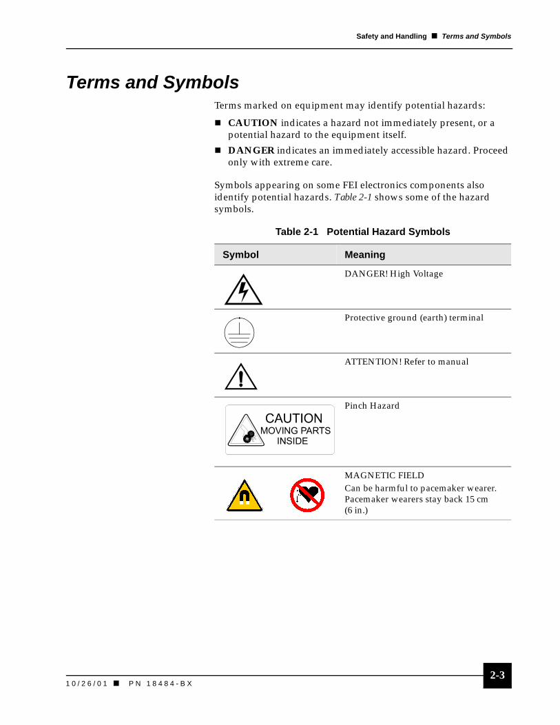
Symbols appearing on some FEI electronics components also identify potential hazards. Table 2-1 shows some of the hazard symbols.
Table 2-1 Potential Hazard Symbols
Symbol Meaning
DANGER! High Voltage
Protective ground (earth) terminal
ATTENTION! Refer to manual
Pinch Hazard
MAGNETIC FIELDCan be harmful to pacemaker wearer. Pacemaker wearers stay back 15 cm (6 in.)

2-4P N 1 8 4 8 4 - B X ��1 0 / 2 6 / 0 1
Safety and Handling � Operation, Maintenance, and Service
Operation, Maintenance, and ServiceEach phase of column operation and maintenance requires a unique set of knowledge and skills.
Trained PersonnelAllow only trained personnel to perform maintenance procedures. There may be additional safety and handling issues not mentioned in this manual. Contact FEI Beam Tech Customer Service at (503) 726-2800 for information about FEI training.
� Always observe appropriate safety practices in dealing with electronic circuitry.
� Read and understand the safety precautions in this chapter and throughout the manual.
� Observe industry-approved safety methods and procedures.
If you have any doubt regarding approved safety procedures, contact safety personnel at your company, FEI Beam Tech Customer Service at (503) 726-2800, or representatives of your state, territory or province, or federal government.
Table 2-2 Training Requirements
Function Training Required
Operation All focusing column operators should receive training on the focusing column and system operating procedures. In addition, all operators should read and understand the Digital Deflection System User’s Guide, Digital High Voltage Power Supply User’s Guide, and this user’s guide.
Maintenance Maintenance includes routine maintenance and installation of the focusing column. Only persons specifically trained in these operations should perform them. Consult FEI for training requirements.
Service Service includes repair and replacement of damaged or defective components. Only trained technical service personnel who are familiar with shock hazards and safety precautions should perform service operations.

2-51 0 / 2 6 / 0 1 ��P N 1 8 4 8 4 - B X
Safety and Handling � Voltages
VoltagesAccording to the American National Standards Institute (ANSI) guidelines, a shock hazard exists when voltage levels are present that are 30 V rms or 42.4 V peak.
Follow these recommendations:
� Operators and service personnel must be trained on potential safety hazards and safe techniques. No person should perform any operations without prior training.
� Operators must observe all warnings and cautions encountered on the system and in the manuals.
� Use extreme caution whenever a shock hazard is present.
As a good safety precaution, before measuring an unknown circuit, always expect a hazardous voltage.
Interlocks
Interlocks for FEI Components FEI components include safety interlocks to minimize high voltage hazards and provide protection for system users of FEI components.
Overriding InterlocksAfter completing a procedure that includes overriding an interlock, always reset (or reconnect) and test the interlock before proceeding. Cover interlocks reset automatically when the covers are replaced. Refer to “Trips and Interlocks” on page 7-2.
High Voltage Power SupplyBefore servicing equipment, wait 30 seconds after turning off the high voltage power supply (HVPS) to ensure all high voltage points are at ground potential. The power supply takes up to 30 seconds for high voltage to decay to 0 volts after being turned off. However, the status in the LED display area will register zero volts immediately.
WA
RN
ING
!
FEI components may have potentially lethal voltages (up to 30 kV).
WA
RN
ING
!
Overriding interlocks is very dangerous and should never be done by untrained personnel.
See also
Digital High Voltage Power Supply User’s Guide, PN 95721

2-6P N 1 8 4 8 4 - B X ��1 0 / 2 6 / 0 1
Safety and Handling � Voltages
Line VoltageBefore performing service or maintenance, completely disconnect the unit from line voltage by disconnecting the AC plug from the AC power source.
Line voltage (120 to 240 V AC) may be present in various locations within the system, even when the system or instrument is turned off.
Cords/CablesNever connect or disconnect any cables or connections while power is applied to the system or components. Doing so is potentially hazardous to service personnel and could cause damage to the system or its components.
AC CordsOnly plug the unit AC cords into an approved power source. Only use power cords that are in good condition. When replacing an AC cord, use one rated to at least the rating of the replaced AC cord.
Miscellaneous CablesCheck cables periodically for possible wear, cracks, or breaks. If any defects are found, replace with FEI-approved cables.
Mains PowerThe system mains power should only be plugged into the approved power receptacle, as identified by system documentation.
Test LeadsIf you are a trained service person, performing service on the system, remember the following:
� Inspect test leads for wear, cracks, and breaks before each use.
Replace any test leads showing such defects with test leads meeting the requirements called for by the manufacturer of the test instrument.
� Do not touch the test leads or the instrument while power is applied to a circuit under test.

2-71 0 / 2 6 / 0 1 ��P N 1 8 4 8 4 - B X
Safety and Handling � Chemicals
GroundThe 2LE column and FEI electrical components must be grounded to operate safely.
� Do not use an ungrounded power source.
� Do not disconnect the grounding of any component.
In the event of loss of a ground connection, all accessible conductive parts (including knobs and controls that may appear insulated) can render an electric shock.
Cover/PanelsOnly operate or plug in any electrical unit if the protective covers and panels are installed.
Only qualified persons aware of the electrical hazards should perform maintenance or service operations.
FusesOnly trained service personnel should replace fuses. Replace fuses only with fuses of the same type, voltage rating, and current rating.
Chemicals
Material Safety Data SheetsBefore using or handling any chemical, obtain and read the Material Safety Data Sheet (MSDS) to become aware of hazards and how to avoid them.
SolventsBefore using any solvents, obtain and read the MSDS relating to the substance and remember the following:
� Avoid hazards listed on the MSDS.
� Use all solvents carefully and in sparing quantities.
� Avoid spillage, skin contact, eye contact, and vapor inhalation.
NitrogenNitrogen may be used to vent the system. Nitrogen is not poisonous, but it is a potential asphyxiant.
DA
NG
ER
!
Electrical shock may occur upon the loss of a protective ground system.
ELECTRICAL HAZARD
WA
RN
ING
!
Special handling is required when replacing fuses.
WA
RN
ING
! Read the applicable MSDS prior to using or handling any chemical.Avoid all spillage, body and eye contact, and vapor inhalation when working with chemicals.
WA
RN
ING
!
Nitrogen is a potential asphyxiant. Exercise care when handling.
2-8P N 1 8 4 8 4 - B X ��1 0 / 2 6 / 0 1
Safety and Handling � Miscellaneous Precautions
Miscellaneous Precautions
Do Not Service AloneOnly perform internal service or adjustments if you are a trained service person and another person capable of rendering first aid or resuscitation is in the immediate vicinity
EnvironmentAlways ensure a safe environment when performing service or maintenance. Keep your hands dry and stand on a dry, insulated surface capable of insulating you from the accessed voltages.
Electric FansSome instruments in the system may be air-cooled, remember the following:
� Do not block the air flow to or from the fans. Periodic filter maintenance may be required to prevent overheating.
� Do not operate fans with the protective covers or filters removed.
� Keep fingers, loose clothing, etc. away from fans.
High Voltage Power Supply VentilationMake sure all ventilation openings on the HVPS top and bottom covers remain unobstructed. If the local temperature approaches or exceeds 40°C (104°F) it is advisable to install a fan to blow forced air upwards through the ventilation grills.
CorrosionSome FEI components are painted, plated, or otherwise treated to resist corrosion.
Observe the following precautions:
� Handle and store all components properly to prevent corrosion.
� Keep components normally operated under vacuum (such as the focusing column) evacuated whenever possible. If such components will not be used, store in a dust-free environment.
� If such components are not under vacuum for an extended period, backfill with clean, dry nitrogen if possible.

P N 1 8 4 8 4 - B X
Chapter 3 Hardware and Theory
Overview . . . . . . . . . . . . . . . . . . . . . . . . 3-1Two Lens Electron
Column Subsystems . . . . . . . . . . . . . . 3-1
External Column Features . . . . . . . . . . 3-2Column Vacuum Chamber
and Feedthroughs . . . . . . . . . . . . . . . . 3-2Magnetic Shields. . . . . . . . . . . . . . . . . . . 3-3
Internal Column Features. . . . . . . . . . . 3-4Column Optical Design . . . . . . . . . . . . . . 3-4
Electronics. . . . . . . . . . . . . . . . . . . . . . 3-13High Voltage Power Supply
and Manual User Interface. . . . . . . . . 3-13Digital Deflection Controller. . . . . . . . . . 3-13

3-1P N 1 8 4 8 4 - B X ��1 0 / 2 6 / 0 1
3Hardware and Theory
Overview
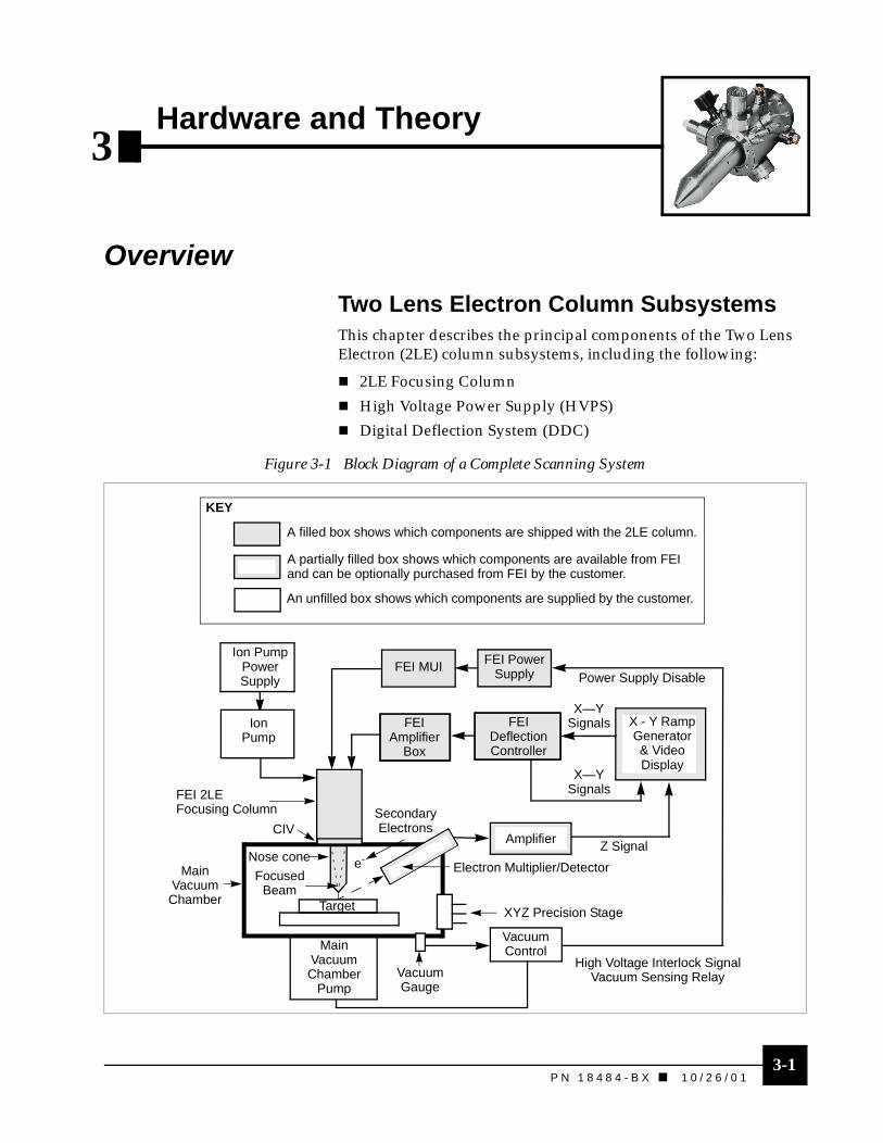
Two Lens Electron Column SubsystemsThis chapter describes the principal components of the Two Lens Electron (2LE) column subsystems, including the following:
� 2LE Focusing Column
� High Voltage Power Supply (HVPS)
� Digital Deflection System (DDC)
Figure 3-1 Block Diagram of a Complete Scanning System
Ion PumpPowerSupply
Ion Pump
FEI Power Supply
FEIAmplifier
Box
FEIDeflectionController
X - Y RampGenerator& Video Display
Amplifier
VacuumControlMain
VacuumChamber
Pump
Nose cone
FocusedBeam
SecondaryElectrons
e-
VacuumGauge
XYZ Precision Stage
MainVacuumChamber Target
FEI 2LE Focusing Column
CIV
X—YSignals
Z Signal
X—YSignals
Power Supply Disable
High Voltage Interlock SignalVacuum Sensing Relay
KEY
A filled box shows which components are shipped with the 2LE column.
An unfilled box shows which components are supplied by the customer.
A partially filled box shows which components are available from FEI and can be optionally purchased from FEI by the customer.
Electron Multiplier/Detector
FEI MUI

3-2P N 1 8 4 8 4 - B X ��1 0 / 2 6 / 0 1
Hardware and Theory � External Column Features
External Column Features
Column Vacuum Chamber and FeedthroughsStarting at the top of the 2LE column vacuum chamber, while facing the chamber window, observe the following:
� 5-pin high voltage (HV) feedthrough connecting to the chamber by a 4.62-in. Conflat flange
� Emitter source alignment knobs align the emitter assembly to Lens 1
� Chamber window
� Ion getter pump connection flange
� 20-pin feedthrough for beam steering and deflection
� HV feedthrough for Lens 2
� Bayonet Neil-Concelman (BNC) connector feedthrough for the Faraday cup beam current measurement
� 4.5-in. Conflat flange mounts the column to the chamber on your system
Figure 3-2 Column Vacuum Chamber, Chamber Window View
Chamber Window
Emitter SourceAlignment Knobs
BNC Feedthrough
20-pin Feedthrough
Ion Getter Pump connection flange
5-pin High Voltage Feedthrough
High Voltage Feedthrough for Lens 2
4.5-in. Conflat flange
4.26 in. Conflat Flange

3-31 0 / 2 6 / 0 1 ��P N 1 8 4 8 4 - B X
Hardware and Theory � External Column Features
Starting at the top of the column vacuum system, while facing the CIV view, observe the following:
� Lens 2 grounding cable
� Ion getter pump elbow (recommended)
� Ion getter pump connection flange
� HV feedthrough for Lens 2
� 20-pin feedthrough
� Column isolation valve (CIV)
� Compressed air line to CIV
Magnetic ShieldsA magnetic shield surrounds the chamber body to shield the column beam from stray magnetic fields. A second magnetic shield, below the mounting flange, surrounds Lens 2, including the steering, deflection, and beam current measuring systems. It shields the beam traveling through the lower column.
Figure 3-3 Column Vacuum Chamber, CIV view
Lens 2 Grounding Cable
Ion Getter Pump connection flange
Lens 2 HV feedthrough
Column Isolation Valve
Compressed Air Line
20-pin DeflectionFeedthrough
Ion Getter PumpElbow (recommended)
NO
TE
The lower shield beneath the mounting flange is not a vacuum seal. Therefore, the Lens 2 section of the column will be exposed to your system’s chamber environment.
3-4P N 1 8 4 8 4 - B X ��1 0 / 2 6 / 0 1
Hardware and Theory � Internal Column Features
Internal Column Features
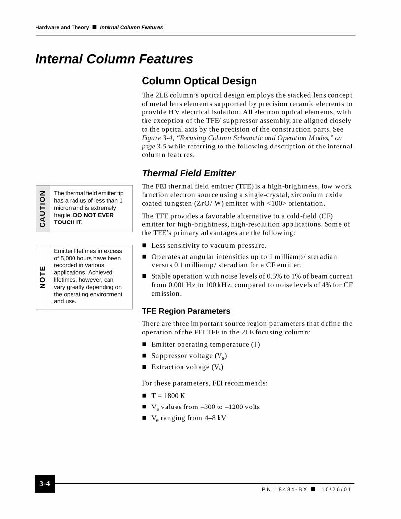
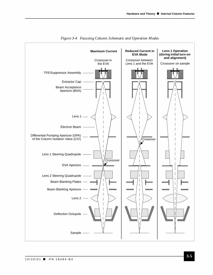
Column Optical DesignThe 2LE column’s optical design employs the stacked lens concept of metal lens elements supported by precision ceramic elements to provide HV electrical isolation. All electron optical elements, with the exception of the TFE/suppressor assembly, are aligned closely to the optical axis by the precision of the construction parts. See Figure 3-4, “Focusing Column Schematic and Operation Modes,” on page 3-5 while referring to the following description of the internal column features.
Thermal Field Emitter The FEI thermal field emitter (TFE) is a high-brightness, low work function electron source using a single-crystal, zirconium oxide coated tungsten (ZrO/W) emitter with <100> orientation.
The TFE provides a favorable alternative to a cold-field (CF) emitter for high-brightness, high-resolution applications. Some of the TFE’s primary advantages are the following:
� Less sensitivity to vacuum pressure.
� Operates at angular intensities up to 1 milliamp/steradian versus 0.1 milliamp/steradian for a CF emitter.
� Stable operation with noise levels of 0.5% to 1% of beam current from 0.001 Hz to 100 kHz, compared to noise levels of 4% for CF emission.
TFE Region Parameters
There are three important source region parameters that define the operation of the FEI TFE in the 2LE focusing column:
� Emitter operating temperature (T)
� Suppressor voltage (Vs)
� Extraction voltage (Ve)
For these parameters, FEI recommends:
� T = 1800 K
� Vs values from –300 to –1200 volts
� Ve ranging from 4–8 kV
CA
UT
ION The thermal field emitter tip
has a radius of less than 1 micron and is extremely fragile. DO NOT EVER TOUCH IT.
NO
TE
Emitter lifetimes in excess of 5,000 hours have been recorded in various applications. Achieved lifetimes, however, can vary greatly depending on the operating environment and use.
3-51 0 / 2 6 / 0 1 ��P N 1 8 4 8 4 - B X
Hardware and Theory � Internal Column Features
Figure 3-4 Focusing Column Schematic and Operation Modes
TFE/Suppressor Assembly
Extractor Cap
Beam AcceptanceAperture (BAA)
Lens 1
Lens 1 Steering Quadrupole
EVA Aperture
Lens 2 Steering Quadrupole
Beam Blanking Plates
Lens 2
Deflection Octupole
Sample
Beam Blanking Aperture
Differential Pumping Aperture (DPA)of the Column Isolation Valve (CIV)
Crossover between Lens 1 and the EVA Crossover on sample
Crossover in the EVA
Crossover
Lens 1 Operation(during initial turn-on
and alignment)
Reduced Current in EVA Mode
Maximum Current
Electron Beam
Crossover

3-6P N 1 8 4 8 4 - B X ��1 0 / 2 6 / 0 1
Hardware and Theory � Internal Column Features
Effects of Oxygen or Nitrogen on the TFE
Oxygen Poisoning
Oxygen acts as a poison to the low work function properties of the TFE. High partial pressures of oxygen in your system can first depress and, if they persist or become too high, then cut off emission from the source. Source poisoning from oxygen is generally a reversible process.
To reverse oxygen poisoning:
Leave the extraction voltage and heating current unchanged and wait for the good vacuum and heating to take effect. The source will return to normal emission when pumping has decreased the local pressure to levels that will allow the source to desorb the oxygen that poisoned it.
Nitrogen or Air Poisoning
Occasionally, after a source has been exposed to air or nitrogen, or has been shut off for a long period of time, the TFE will not restart due to the formation of zirconium nitride on the surface.
To remove the zirconium nitride:
1. Temporarily heating, for 5 to 10 minutes at 1900 K in the presence of normal extraction voltages, will usually restore the emission.
2. Reduce the source temperature to 1800 K after the temporary heating at 1900 K.

3-71 0 / 2 6 / 0 1 ��P N 1 8 4 8 4 - B X
Hardware and Theory � Internal Column Features
TFE/Suppressor AssemblyThe TFE/suppressor assembly mounts inside the column chamber near the 5-pin feedthrough. The suppressor serves two functions:
� It shields the TFE from the high electric field generated by the extraction electrode, limiting the total emission current.
� It allows fine control of the emission current by voltage applied to the suppressor. The suppressor voltage is used to vary the field on the TFE while maintaining constant extractor voltage.
Extractor AssemblyThe extractor assembly is the extraction electrode for the TFE. See Figure 3-4 on page 3-5.
This assembly consists of the following main components:
� Cylindrical extractor cap
The extractor cap mounts by three screws to the extractor body. This attachment allows for easy extractor cap removal for maintenance.
� Beam acceptance aperture (BAA)
The BAA mounts below the extractor cap in the extractor body.
� Extractor body
The extractor body serves as the first element of Lens 1.
Figure 3-5 TFE/Suppressor Assembly (Cross Section)
Filament Pins
Ceramic Base
Outgassing Holes
TFE
Suppressor
3-8P N 1 8 4 8 4 - B X ��1 0 / 2 6 / 0 1
Hardware and Theory � Internal Column Features
Lens 1 and Lens 2Two asymmetric, three-element, electrostatic lenses focus the emitted electrons into a beam and determine the beam parameters.
Lens 1 is located after the extractor assembly and Lens 2 is located after the Lens 1 steering quadrupole. See Figure 3-4 on page 3-5.
Quadrupole Steering PlatesTwo sets of quadrupole plates control the X and Y direction positioning of the beam. The first set of parallel plates are followed by a second set of parallel plates orthogonal to the first.
Manual TFE positioning aligns the TFE to the optical axis of Lens 1 and the BDA. The first quadrupole adjusts the beam position so the beam travels through the center of the BDA. The second quadrupole then aligns the beam from the BDA’s optical axis to the optical axis of Lens 2. This alignment is achieved by wobbling Lens 2 and adjusting the beam centering controls on the digital deflection controller (DDC).
Electronically Variable ApertureThis aperture is referred to as an electronically variable aperture (EVA) because the effective aperture position (crossover position) is changed by varying the Lens 1 focus voltage. Using Lens 1 to change the crossover position allows you to easily change the electron probe diameter and beam current.
When varying the Lens 1 voltage, consider the following conditions:
� Always operate the column with the crossover above the BDA.
� Operation with the crossover between the BDA and Lens 2 should not be attempted because it provides sub-optimal imaging performance.
See also
Digital Deflection Controller User’s Guide, PN 95721, Tutorial
NO
TE
Varying the Lens 1 voltage to change the crossover position can be compared to the act of applying a weight to a vertical rope. Increasing the mass of the weight moves it down the rope. n As the Lens 1 voltage is increased, the crossover position moves
down the column between Lens 1 and Lens 2 to obtain the desired effective aperture acceptance half angle (beam current).
n Increasing the Lens 1 voltage weakens the lens by bringing the lens voltage closer to the extraction voltage.
3-91 0 / 2 6 / 0 1 ��P N 1 8 4 8 4 - B X
Hardware and Theory � Internal Column Features
Beam Defining Aperture
The BDA is installed between the Lens 1 and the Lens 2 steering quadrupoles. See Figure 3-4 on page 3-5.
In the 2LE column, the crossover position of the beam works in conjunction with the BDA to define the beam size. When adjusting beam crossover position, consider the following conditions:
� The crossover position can be moved above the aperture by changing Lens 1 voltage to obtain the desired effective aperture acceptance half angle (beam current).
� The angle at which the crossover impinges upon the physical BDA determines the effective BDA.
Column Isolation Valve The 2LE column is equipped with a gate valve, called an integral column isolation valve (CIV), that is located after Lens 1 near the Conflat mounting flange.
When the CIV is closed, a vacuum seal isolates the vacuum levels of the electron source (Lens 1 region) from the sample chamber (Lens 2 region).
Also, when the CIV is closed, it allows for the replacement of the TFE/suppressor assembly while the sample chamber is at vacuum or while bringing the sample chamber to higher pressure while the TFE region remains at vacuum, for example, during sample change.
Differential Pumping Aperture
The differential pumping aperture (DPA), located in the CIV, allows passage of the electron beam while restricting conduction. Pumping of the source region is via an ion getter pump (IGP) mounted on the side of the column.
TFE operation requires a vacuum of less than 5 x 10⁻⁹ torr and differential pumping evacuates the chamber to ensure the source region remains at proper operating pressure.
The column maintains a pressure difference of one to two orders of magnitude between the column chamber and sample sides of the DPA. This is true under normal high-vacuum conditions of 1 x 10⁻⁷ torr to 1 x 10 -9 torr in the main chamber (conditions when the CIV can be open) pressure regions, where ion pumps can operate.
3-10P N 1 8 4 8 4 - B X ��1 0 / 2 6 / 0 1
Hardware and Theory � Internal Column Features
The range of pressure differential depends on the DPA diameter and the relative pumping speeds of the column and user chamber pumps. The differential pressure increases as the DPA diameter decreases. FEI recommends using at least a 20 l/s diode or triode ion pump.
Beam Blanking AssemblyThe beam blanking assembly, located between the Lens 2 steering quadrupoles and Lens 2, provides beam blanking in the focusing column. See Figure 3-4 on page 3-5.
The beam blanking assembly consists of the following components:
� Blanking plates
� Beam blanking aperture (Faraday cup in the blanking aperture plate)
� BNC connector for measuring blanked current (normally grounded)
Beam Blanking System
The electron beam traveling through the column passes through an opening known as the blanking aperture. Beam blanking diverts the beam away from the aperture and into the Faraday cup which surrounds the aperture and is used to measure the current. The DDC applies a charge to parallel blanking plates near the aperture to divert the beam.
When the deflected beam strikes the blanking aperture plate the following conditions occur:
� The beam current (measured at the blanking aperture plate) can be monitored.
� The beam current monitoring BNC connector, on the side of the focusing column or on the DDC, provides electrical connection to the blanking aperture plate.
� The BNC connector provides grounding for the aperture only when it is shorted or connected to a meter.
Blanking requires a total blanking voltage of approximately 160 V plate–to–plate (for a 25 kV beam).
� The DDC provides plate–to–plate voltage of 292 V.
� The minimum blanking time is less than 100 nanoseconds using an external trigger.
See also
Digital Deflection System User’s Guide,PN 95721, User Interface
NO
TE Beam blanking current is
important during alignment and general operation
3-111 0 / 2 6 / 0 1 ��P N 1 8 4 8 4 - B X
Hardware and Theory � Internal Column Features
Purpose of the Faraday Cup
The beam current is the best indicator of the selected aperture because the HVPS meters are accurate to only 1 percent, and the aperture is highly dependent on the exact values of the beam voltage, extractor voltage, and Lens 1 voltage.
Deflection Octupole The deflection octupole, located below the Lens 2 assembly, provides scan and shift (fine field of view movement) as well as beam astigmatism correction.
The octupole construction includes eight metal sectors in precisely machined dielectric tube elements. The magnification electronics generate eight appropriate deflection voltages (derived from X and Y electrical inputs) provided to the octupole.
Two types of electrical fields are superimposed on the octupole element. Note the distinction between octupole (referring to the physical deflector with eight poles or plates) and dipole or quadrupole fields (referring to electrostatic fields generated by the deflector).
There are two types of fields:
� Scan and Shift (X and Y dipole fields)
� Stigmator (0 and 45° quadrupole fields)
3-12P N 1 8 4 8 4 - B X ��1 0 / 2 6 / 0 1
Hardware and Theory � Internal Column Features
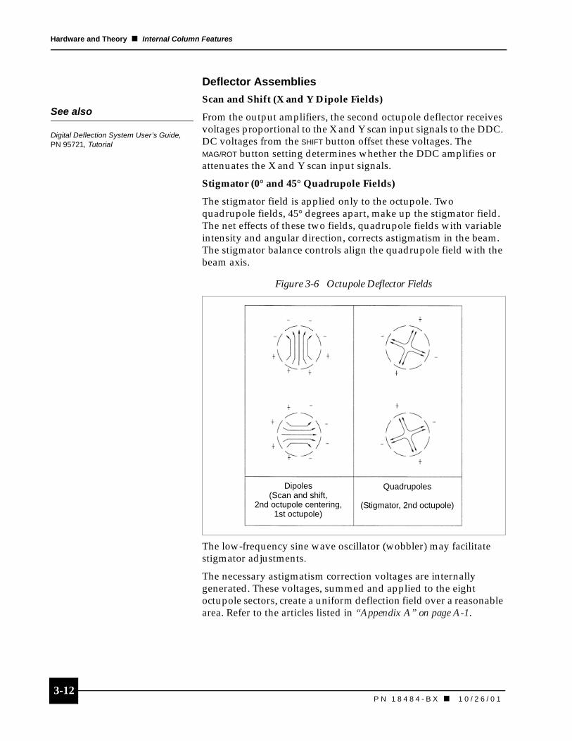
Deflector Assemblies
Scan and Shift (X and Y Dipole Fields)
From the output amplifiers, the second octupole deflector receives voltages proportional to the X and Y scan input signals to the DDC. DC voltages from the SHIFT button offset these voltages. The MAG/ROT button setting determines whether the DDC amplifies or attenuates the X and Y scan input signals.
Stigmator (0° and 45° Quadrupole Fields)
The stigmator field is applied only to the octupole. Two quadrupole fields, 45° degrees apart, make up the stigmator field. The net effects of these two fields, quadrupole fields with variable intensity and angular direction, corrects astigmatism in the beam. The stigmator balance controls align the quadrupole field with the beam axis.
The low-frequency sine wave oscillator (wobbler) may facilitate stigmator adjustments.
The necessary astigmatism correction voltages are internally generated. These voltages, summed and applied to the eight octupole sectors, create a uniform deflection field over a reasonable area. Refer to the articles listed in “Appendix A” on page A-1.
Figure 3-6 Octupole Deflector Fields
See also
Digital Deflection System User’s Guide,PN 95721, Tutorial
Dipoles(Scan and shift,
2nd octupole centering, 1st octupole)
Quadrupoles
(Stigmator, 2nd octupole)
3-131 0 / 2 6 / 0 1 ��P N 1 8 4 8 4 - B X
Hardware and Theory � Electronics
ElectronicsThe electronics consist of these three systems:
� High voltage power supply (HVPS)
� manual user interface (MUI)
� Digital deflection controller (DDC) system
Refer to these system’s user’s manuals for specific instructions on operating the electronics.
High Voltage Power Supply and Manual User InterfaceThe HVPS provides the voltages and currents necessary to turn on and focus the column. All power supply adjustments are made on the MUI or from a computer running appropriate software.
The HVPS powers and the MUI adjusts the following systems:
� Source heating
� Source operation
� Beam voltage and lens voltage
� Lens wobbler
Digital Deflection ControllerThe DDC consists of a controller and postamplifier. The controller connects to the postamplifier via a 15-foot, 20-pin cable. The postamplifier connects to the column via a 4-foot, 20-pin cable.
The DDC regulates the following:
� Magnification and magnification tracking
� Deflection and scanning
� Stigmation correction
� Alignment
� Image rotation
� Scan modes
WA
RN
ING
! Turn off mains power and disconnect the mains socket before attempting to remove any covers or disconnect HV cables or fiber-optic connections.
See also
Digital High Voltage Power Supply User’s Guide, PN 19946
See also
Digital Deflection System User’s Guide,PN 95721

P N 1 8 4 8 4 - B X
Chapter 4 Scanning System Installation
Overview . . . . . . . . . . . . . . . . . . . . . . . . 4-1Handling and Care of the Column. . . . . . 4-1
Preinstallation Preparation . . . . . . . . . 4-2Necessary Equipment . . . . . . . . . . . . . . . 4-2
Installing the Focusing Column. . . . . . 4-3
Installing the Ion Getter Pump . . . . . . . 4-4Preventing Direct Path Pumping . . . . . . . 4-4
Grounding Protocol . . . . . . . . . . . . . . . 4-5Eliminating Ground Loops. . . . . . . . . . . . 4-5
Installing the High Voltage Power Supply . . . . . . . 4-6
Before You Begin . . . . . . . . . . . . . . . . . . 4-6
Installing the Digital Deflection Controller . . . . . . . 4-8
Installing a Picoammeter . . . . . . . . . . . 4-8
Connecting AC Power . . . . . . . . . . . . . 4-9Power Connection Checklist . . . . . . . . . . 4-9
Final Preparation. . . . . . . . . . . . . . . . . 4-10Baking the Column . . . . . . . . . . . . . . . . 4-10Preparation After Bakeout . . . . . . . . . . . 4-12

4-1P N 1 8 4 8 4 - B X � 1 0 / 2 6 / 0 1
4Scanning System Installation
Overview
Handling and Care of the ColumnBefore you begin installation, read these recommendations on the handling, care, and installation of the 2LE column for your vacuum system:
� The 2LE column shield cannot bear any weight. Never use the shield to support or pick up the column. Do not remove the shield, unless directed to do so by FEI Beam Tech Customer Service; it protects extremely delicate optical components.
� Only expose the internal parts of the column in a clean room under a laminar flow hood.
� Wear Class 100 powder-free gloves when handling internal components.
� Store the focusing column in a cool, dry atmosphere with desiccant when it is not under a vacuum.
� During prolonged periods off the vacuum, pump the column to a rough vacuum with an oil-free pump and cover it with the shipping container.
� Never operate the focusing column at a pressure > 5 x 10⁻⁹ torr.
� Never turn on the high voltage (HV) portion of the high voltage power supply (HVPS) without first connecting the HV cables and checking the vacuum.
� Do not position the column so that weight is bearing on the ceramic 5-pin HV feedthrough unless you have installed the protective cap provided with the column.
� Use isopropanol to prepare surfaces for vacuum seal.
CA
UT
ION Failure to follow these
recommendations may result in damage to the focusing column or poor performance.
4-2P N 1 8 4 8 4 - B X � 1 0 / 2 6 / 0 1
Scanning System Installation � Preinstallation Preparation
Preinstallation Preparation
Necessary EquipmentBefore you begin installation, you need the following items from the tool kit supplied with the focusing column:
� 1/4 x 5/16 box end wrench
� 5/16-24 hex nut (8)
� 5/16-24 stud (8)
� 5/16 washer (8)
� 2.75-in. oxygen free high conductivity (OFHC) copper gasket (2)
� 4.5-in. OFHC copper gasket (2)
� 4.625-in. OFHC copper gasket (2)
� Braycote (vacuum grease)
You will also need to supply the following items:
� Dry, filtered nitrogen
� Pair of Class 100 powder-free latex rubber gloves
� Aluminum foil to wrap the column. Household type is fine.
� Laminar flow hood is optional but highly recommended.
� Isopropanol
� Ion pump (for the upper portion of the column)
You will also need an assistant to help remove the column from the box and to bolt the column onto the vacuum system.
4-3P N 1 8 4 8 4 - B X ��1 0 / 2 6 / 0 1
Scanning System Installation � Installing the Focusing Column
Installing the Focusing Column 1. Prepare the sealing surfaces:
� Access the 4.5-in. Conflat flange column sealing surface of your specimen chamber. See Figure 3-2, “Column Vacuum Chamber, Chamber Window View,” on page 3-2.
� Inspect the specimen chamber flange sealing surfaces and remove any particles using a lint-free cloth.
� Clean the Conflat flange sealing surfaces with isopropanol.
� Use a new 4.5-in. ultra-high vacuum (UHV) copper gasket when installing the column on your specimen chamber.
2. With an assistant:
� Remove the column from its packaging. Be careful not to get dust or packaging material onto the column.
� Transport the column to the specimen chamber work site and carefully place it either on its side or vertically on its source end.
3. Under a laminar flow bench or in a clean room, remove the shipping cap on the vacuum connection end.
� If you have trouble removing the cap, gently rock the shipping cap back and forth until the seal is broken.
� Save the shipping cap for future use.
4. Place the nose cone of the focusing column into the specimen chamber’s 4.5-in. mounting flange.
5. With an assistant holding the column, bolt the focusing column to your system:
� Hand-tighten the mounting bolts until snug.
� Using the 1/4 x 5/16 box end wrench, in a circular sequence around the flange, tighten the bolts in 1/4 turn increments until the flanges have metal-to-metal contact.
NO
TE
Prior to shipment, the column was backfilled with dry nitrogen. When you loosen the cap, nitrogen flows out to help keep dust and other contaminants out of the column.
NO
TE
Save the packaging.Otherwise, it will cost approximately $500 for new crating should you need to return the column to FEI.
4-4P N 1 8 4 8 4 - B X � 1 0 / 2 6 / 0 1
Scanning System Installation � Installing the Ion Getter Pump
Installing the Ion Getter PumpThe ion getter pump (IGP) must meet the following requirements:
� Have a capacity of 20 or more liters per second.
� Connect to the focusing column via the 2.75-in. pumping port flange.
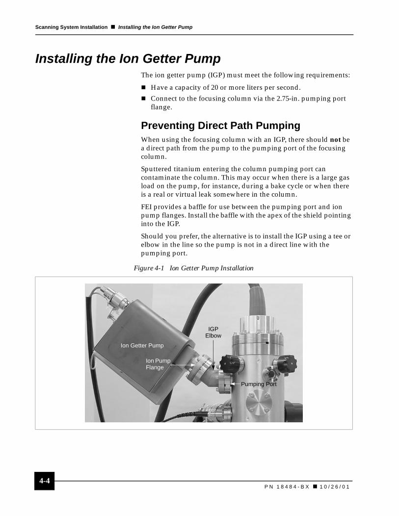
Preventing Direct Path PumpingWhen using the focusing column with an IGP, there should not be a direct path from the pump to the pumping port of the focusing column.
Sputtered titanium entering the column pumping port can contaminate the column. This may occur when there is a large gas load on the pump, for instance, during a bake cycle or when there is a real or virtual leak somewhere in the column.
FEI provides a baffle for use between the pumping port and ion pump flanges. Install the baffle with the apex of the shield pointing into the IGP.
Should you prefer, the alternative is to install the IGP using a tee or elbow in the line so the pump is not in a direct line with the pumping port.
Figure 4-1 Ion Getter Pump Installation
IGPElbow
Pumping Port
Ion Pump Flange
Ion Getter Pump

4-5P N 1 8 4 8 4 - B X ��1 0 / 2 6 / 0 1
Scanning System Installation � Grounding Protocol
Grounding Protocol
Eliminating Ground LoopsTo achieve optimum 2LE column performance and eliminate or minimize ground loops in the system: plug all electrical equipment into the same power line circuit, preferably into a common outlet strip.
One electronics rack should be used to house all equipment. Each piece of electronic equipment provided by FEI has a ground lug that should be connected to an unpainted surface of the electronics rack.
The best common ground reference point is not always easy to locate. It may take a little experimentation to find the correct reference point for your particular environment. Begin by using the vacuum system as the reference point.
Ideally, the grounding system should emulate a tree trunk and its branches. Think of the reference point as the trunk and the individual pieces of electrical equipment as the branches. All equipment should be grounded to the common reference point (the trunk).
4-6P N 1 8 4 8 4 - B X � 1 0 / 2 6 / 0 1
Scanning System Installation � Installing the High Voltage Power Supply
Installing the High Voltage Power Supply
Before You BeginObtain from FEI and read the Digital High Voltage Power Supply User’s Guide, PN 19946.
� Before you install the HVPS, it is recommended that you install a vacuum sensing relay. Refer to the Digital High Voltage Power Supply User’s Guide for instruction about installing the relay.
� Ensure that the correct and the same voltage settings are selected on the HVPS and manual user interface (MUI). If they are not, the electronics will be damaged during operation.
1. Install the HVPS into a 19-in. equipment rack. Use at least four rack mount screws.
� Ground the HVPS to the rack.
� Do not connect the HVPS to the AC power line at this time.
2. Remove the protective shipping cap from the 5-pin HV flange on the top of the column. Set the screws aside for attaching the HVPS cable.
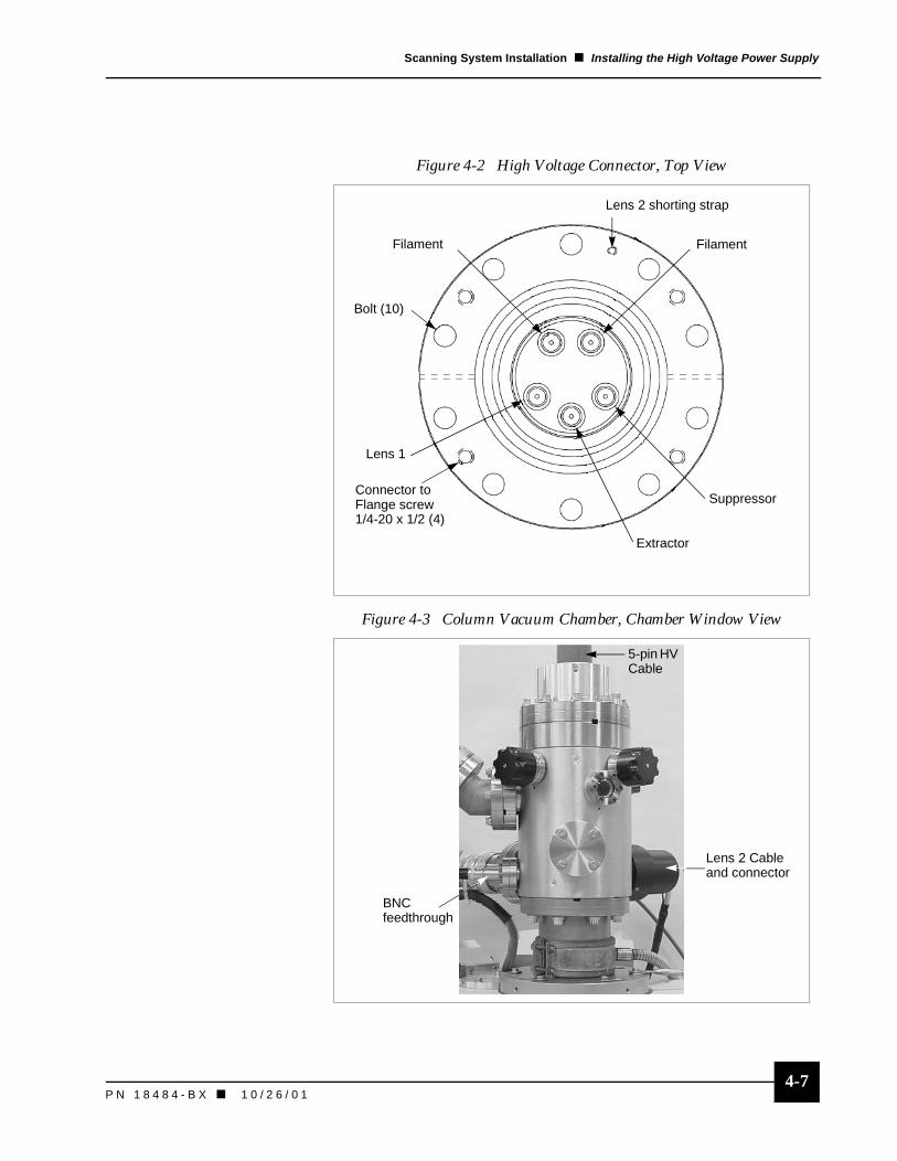
For steps 3 through 7, refer to Figure 4-2, “High Voltage Connector, Top View,” on page 4-7.
3. Attach the 5-pin column HV cable to the 5-pin HV feedthrough at the top of the chamber. Match the orientation of the connector and the feedthrough.
4. Use the four 1/4-20 x 1/2 screws to fasten the connector to the flange.
5. Inspect the Lens 2 cable from the HVPS and remove any particulates from the cable socket.
6. Insert the Lens 2 cable socket into the HV feedthrough receptacle. Screw the black protective cover onto the threaded ceramic feedthough.
7. Screw the Lens 2 shorting strap to the flange of the column.
WA
RN
ING
! This unit is capable of generating lethal voltages. Never plug unit in or turn unit on until you have connected all high voltage cables and grounded all components.
See also
Digital High Voltage Power Supply User’s Guide, PN 19946
NO
TE
Note the asymmetry of the pin configuration of the HV connectors. The two filament pins are separated from the Lens 1 pin, extractor pin, and suppressor pin.
4-7P N 1 8 4 8 4 - B X ��1 0 / 2 6 / 0 1
Scanning System Installation � Installing the High Voltage Power Supply
Figure 4-2 High Voltage Connector, Top View
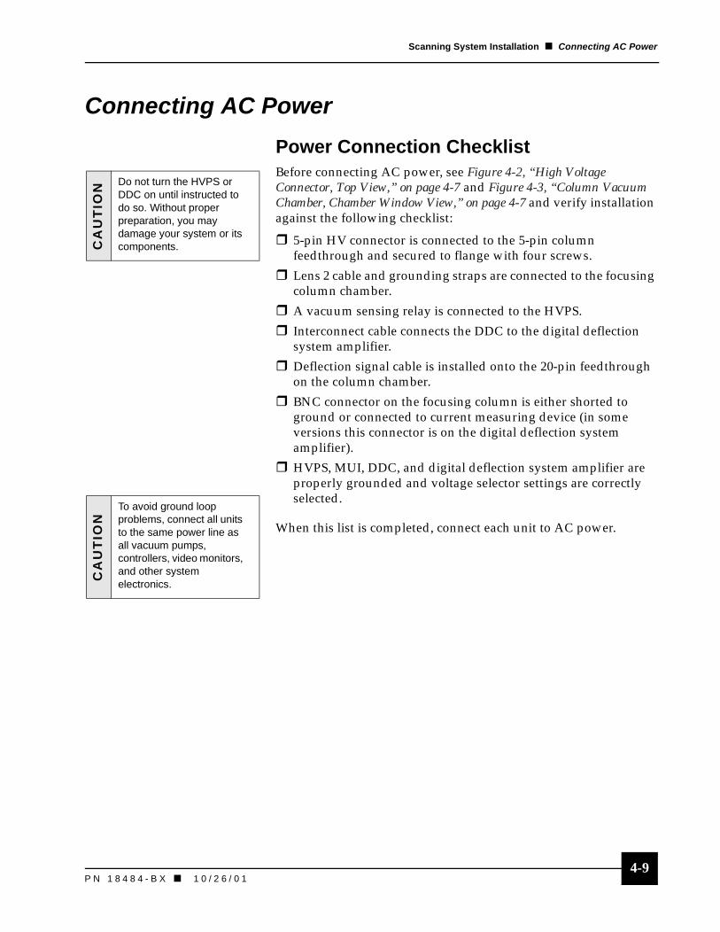
Figure 4-3 Column Vacuum Chamber, Chamber Window View
Connector to Flange screw1/4-20 x 1/2 (4)
FilamentFilament
Bolt (10)
Suppressor
Extractor
Lens 1
Lens 2 shorting strap
5-pin HV Cable
BNC feedthrough
Lens 2 Cable and connector

4-8P N 1 8 4 8 4 - B X � 1 0 / 2 6 / 0 1
Scanning System Installation � Installing the Digital Deflection Controller
Installing the Digital Deflection ControllerBefore you begin, obtain and read FEI’s Digital Deflection System User’s Guide, PN 95721.
To install the DDC:
1. Mount the DDC into a 19-in. rack. Use at least two rack mount screws.
2. Ensure the DDC is grounded to the equipment rack.
3. Connect all appropriate connections.
4. Remove the multipin shorting connector attached to the multipin feedthrough on the column.
5. Connect the free end of the 4-foot deflection signal cable from the digital deflection system amplifier to the 20-pin feedthrough on the column.
6. Set the voltage selector switch on the back of the DDC to the appropriate value for your system.
Installing a PicoammeterIf you install a picoammeter, connect the picoammeter to the Bayonet Neil-Concelman (BNC) connector feedthrough on the column chamber body.
Figure 4-4 Picoammeter Feedthrough
See also
Digital Deflection Controller, 3-13Digital Deflection System User’s Guide,
PN 95721
BNC Feedthrough
PicoammeterCable
4-9P N 1 8 4 8 4 - B X ��1 0 / 2 6 / 0 1
Scanning System Installation � Connecting AC Power
Connecting AC Power
Power Connection ChecklistBefore connecting AC power, see Figure 4-2, “High Voltage Connector, Top View,” on page 4-7 and Figure 4-3, “Column Vacuum Chamber, Chamber Window View,” on page 4-7 and verify installation against the following checklist:
� 5-pin HV connector is connected to the 5-pin column feedthrough and secured to flange with four screws.
� Lens 2 cable and grounding straps are connected to the focusing column chamber.
� A vacuum sensing relay is connected to the HVPS.
� Interconnect cable connects the DDC to the digital deflection system amplifier.
� Deflection signal cable is installed onto the 20-pin feedthrough on the column chamber.
� BNC connector on the focusing column is either shorted to ground or connected to current measuring device (in some versions this connector is on the digital deflection system amplifier).
� HVPS, MUI, DDC, and digital deflection system amplifier are properly grounded and voltage selector settings are correctly selected.
When this list is completed, connect each unit to AC power.
CA
UT
ION Do not turn the HVPS or
DDC on until instructed to do so. Without proper preparation, you may damage your system or its components.
CA
UT
ION
To avoid ground loop problems, connect all units to the same power line as all vacuum pumps, controllers, video monitors, and other system electronics.
4-10P N 1 8 4 8 4 - B X � 1 0 / 2 6 / 0 1
Scanning System Installation � Final Preparation
Final Preparation
Baking the ColumnThis column is not kept under vacuum when shipped. Therefore, you will need to bake the column when preparing it for use. Also, you must rebake the column under the following conditions:
� After normal TFE changes.
� Anytime the emitter/Lens 1 region has been exposed to air.
Bakeout Precautions� Always apply temperature uniformly to the body of the
chamber.
� CIV valve should remain locked-open and unwrapped during bakeout.
� Do not exceed 185°C during bakeout.
� Do not attempt to quickly heat or cool the chamber as temperature nonuniformities can be dangerous to the optical structure of the column.
� Ensure that the electron column is the last item to cool during system bakeout.
Column Bakeout 1. Verify that the CIV is in the
locked-open position to prevent IGP interlock circuitry from closing the valve during bakeout. Refer to “Operating the CIV” on page 5-7.
2. Unscrew and remove the plastic hose fitting from the body of the CIV. High temperatures can damage this piece.C
AU
TIO
N Apply compressed air only in the range of 45 to 80 psi and do not apply more than 80 psi.
4-11P N 1 8 4 8 4 - B X ��1 0 / 2 6 / 0 1
Scanning System Installation � Final Preparation
Heating and Evacuating the Column1. Remove the following electrical connections from the column:
� 5-pin HV connectors
� Lens 2 connector and grounding strap
� BNC connector
� 20-pin deflection cable
2. Install band heaters or heat tape and thermocouples and remember the following:
� The column must have a uniform distribution of heat.
� There must be at least one thermocouple. Three are recommended.
3. The entire column must be covered with at least six layers of aluminum foil or a heat blanket.
4. Evacuate the column using the roughing pump attached to your system. This process could take several hours because the Lens 1 region of the column is evacuated through the differential pumping aperture (DPA). The time depends on your chamber and roughing capabilities.
5. When the pressure in the column is < 5 x 10⁻⁵ torr, turn on the ion pump controller to start the ion pump.
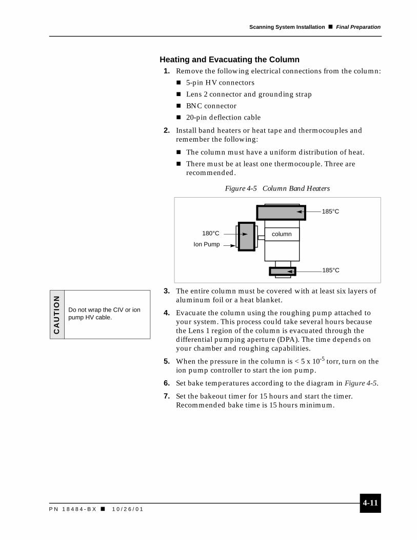
6. Set bake temperatures according to the diagram in Figure 4-5.
7. Set the bakeout timer for 15 hours and start the timer. Recommended bake time is 15 hours minimum.
Figure 4-5 Column Band Heaters
185°C
185°C
180°C column
Ion Pump
CA
UT
ION
Do not wrap the CIV or ion pump HV cable.
4-12P N 1 8 4 8 4 - B X � 1 0 / 2 6 / 0 1
Scanning System Installation � Final Preparation
After Bakeout 1. When bakeout is complete, carefully unwrap the foil from the
ion pump on the column and allow it to cool. A large fan is very helpful to speed up cooling.
2. Once the pump has cooled slightly, unwrap the rest of the column to allow the column to cool faster.
3. Close off the roughing source and remove the aluminum foil.
4. Remove the heat sources and thermocouples.
Once the column is completely cooled, pressure in the column should be < 3.5 x 10⁻⁹ torr.
5. Reinstall the CIV plastic hose fitting.
If pressure is too high, verify that all the hardware is tight. Some fittings can loosen during the high-temperature bake. It may be necessary to do another bake.
Preparation After Bakeout
Cable Connections Before proceeding, verify and correct all cable and component connections made during installation.
Column Vacuum LevelIf the location of the vacuum gauge is some distance from the source and/or connected to the source area by a path with a low conductance, the true pressure in the vicinity of the source will not be known. Therefore, if the base pressure of the system is not much lower than the desired level of 5 x 10⁻⁹ torr, the pressure near the source may well be above the needed 5 x 10⁻⁹ torr minimum.
For safe and stable operation of the source, do not continue with the process until the pressure in the immediate vicinity of the TFE tip is < 5 x 10⁻⁹torr. On your DDC, it is sufficient to measure the vacuum pressure using the ion pump current as an indicator.
Picoammeter InstallationYou may choose to attach a picoammeter to measure the blanking current and/or stage current.
See also
Two Lens Electron Column Subsystems, 3-1
Digital High Voltage Power Supply User’s Guide, PN 19946
CA
UT
ION Attempted operation when
the pressure near the source may be above the needed 5 x 10⁻⁹ torr minimum may lead to catastrophic source failure.
See also
Installing a Picoammeter, 4-8
P N 1 8 4 8 4 - B X
Chapter 5 Column Operation
Overview . . . . . . . . . . . . . . . . . . . . . . . . 5-1Before Turning On the Column . . . . . . . . 5-1Interlocks. . . . . . . . . . . . . . . . . . . . . . . . . 5-1
Column Startup Checklist . . . . . . . . . . 5-2
Operating the Thermal Field Emitter . . . . . . . . . . . . . 5-2
Source Heating . . . . . . . . . . . . . . . . . . . . 5-2Suppressor Voltage. . . . . . . . . . . . . . . . . 5-3Extraction Current . . . . . . . . . . . . . . . . . . 5-4Maintaining TFE Microgeometry . . . . . . . 5-4
High Voltage Conditioning . . . . . . . . . . 5-5Overview . . . . . . . . . . . . . . . . . . . . . . . . . 5-5Beam Voltage Conditioning. . . . . . . . . . . 5-5Lens 2 Voltage Conditioning . . . . . . . . . . 5-6
Initial Turn On . . . . . . . . . . . . . . . . . . . . 5-8Turning On the Column . . . . . . . . . . . . . . 5-8
Aligning the Column . . . . . . . . . . . . . . 5-10Overview . . . . . . . . . . . . . . . . . . . . . . . . 5-10Background . . . . . . . . . . . . . . . . . . . . . . 5-11Column Alignment Checklist . . . . . . . . . 5-14Coarse Alignment Procedures . . . . . . . 5-15Fine Alignment: Lens 1 . . . . . . . . . . . . . 5-17Fine Alignment: Lens 2 . . . . . . . . . . . . . 5-19
Changing Aperture Size . . . . . . . . . . . 5-20
Tips for Column Operation. . . . . . . . . 5-21Beam Diameter
and Working Distance . . . . . . . . . . . . 5-21Beam Diameter and Beam Voltage. . . . 5-21Beam Diameter and Beam Current . . . . 5-21Field of View . . . . . . . . . . . . . . . . . . . . . 5-21Shorting the Blanking Aperture . . . . . . . 5-22Extractor Current. . . . . . . . . . . . . . . . . . 5-22Adjust Video Controls . . . . . . . . . . . . . . 5-22
Full Power Down . . . . . . . . . . . . . . . . . 5-22
Operating Parameters. . . . . . . . . . . . . 5-23


5-1P N 1 8 4 8 4 - B X � 1 0 / 2 6 / 0 1
5Column Operation
Overview
Before Turning On the ColumnThis chapter assumes you have followed all instructions from “Scanning System Installation” on page 4-1 and are familiar with the hardware. If problems occur, refer to “Troubleshooting” on page 7-1.
InterlocksThe 2LE column electronics have interlock circuitry to protect the operator and equipment from hazardous voltages. Refer to the Digital High Voltage Power Supply User’s Guide, PN 19946 for information regarding interlocks.
High Voltage Power Supply InterlocksWhen operating the High Voltage Power Supply (HVPS), remember the following:
� Interlock circuitry disables the HVPS in case of overpressure conditions within the column.
� Internal interlock circuitry ensures that the high voltage turns on only when beam voltage is set to 0 kV.
� If the interlock trips during powerup, confirm the interlock conditions. If necessary, inspect electrical connections.
� If the high voltage turns off during operation, inspect the interlock conditions to determine the cause of the problem. Correct the condition, then restart.
Column Isolation Valve Controller InterlocksThe column isolation valve (CIV) controller must be interlocked so the CIV closes in the event of a specimen chamber overpressure.
Refer to the Digital High Voltage Power Supply User’s Guide for instructions on setting up the interlocks.
CA
UT
ION
Do not operate the column until the pressure is< 5 x 10⁻⁹ torr.
See also
Interlocks, 2-5Trips and Interlocks, 7-2Digital High Voltage Power Supply User’s
Guide, PN 19946
5-2P N 1 8 4 8 4 - B X � 1 0 / 2 6 / 0 1
Column Operation � Column Startup Checklist
Column Startup ChecklistWhen your column is installed, you are ready to follow a series of procedures that lead to a stable, fully operational mode.
The following checklist shows the sequence of these procedures:
� Operating the Thermal Field Emitter, 5-2
� High Voltage Conditioning, 5-5
� Initial Turn On, 5-8
� Aligning the Column, 5-10
� Changing Aperture Size, 5-20
� Tips for Column Operation, 5-21
� Full Power Down, 5-22
Operating the Thermal Field EmitterThe thermal field emitter (TFE) source is not difficult to use; once it is placed in operation, it is stable and fairly rugged. However, due to its unique properties, care should be exercised during the initial turn-on procedure and during subsequent operation to avoid permanent damage. This is particularly true when the TFE is turned on for the first time.
Source HeatingFor a TFE to operate properly, the tip needs to be heated to 1800° ± 50 K. This is done by passing a heating current through the filament structure of the TFE. If the source is heated to < 1650 K, its operation will become unstable.
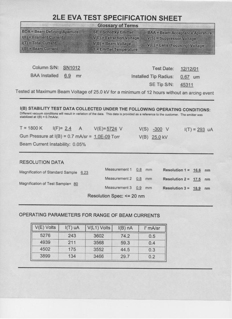
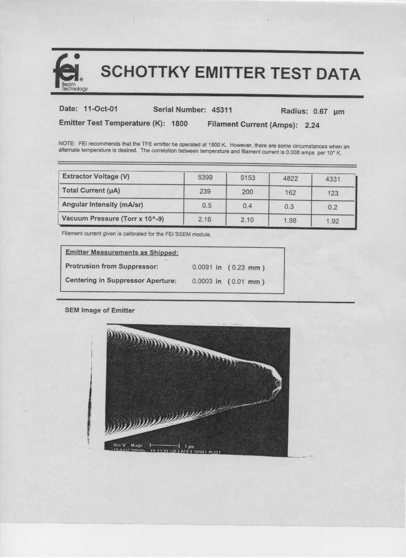
TFE Calibration SheetThis Schottky Emitter Test Data calibration sheet is only supplied when you replace your TFE source. The calibration sheet is only a guide because it is quite unlikely that your operating environment for the TFE will be characterized by the same heat conductance paths as FEI’s test fixture.
This data sheet provides both a beam current/extraction voltage (I/V) table and a heating current calibration generated from measurements taken in the FEI source test fixture.
The primary purpose of these test measurements is to verify that the source has demonstrated a typical set of emission current vs. extraction voltage characteristics and heating requirements at FEI’s test facilities.
See also
Thermal Field Emitter, 3-4
CA
UT
ION If the source is heated
above approximately 1950 K it will be irreversibly damaged due to complete zirconium evaporation.
5-3P N 1 8 4 8 4 - B X � 1 0 / 2 6 / 0 1
Column Operation � Operating the Thermal Field Emitter
When you replace the TFE source, it is recommended that you add 80 mA to the data sheet value to approximate the heating current value you need for operation at 1800 K.
If you order several sources of the same radius, each may have a somewhat different heating current value for 1800 K.
Measuring the TemperatureThe 2LE column is equipped with a window that allows observation of the source. A micro-optical pyrometer is recommended to verify the TFE temperature. See Figure 3-2, “Column Vacuum Chamber, Chamber Window View,” on page 3-2.
Typical disappearing filament pyrometers have temperature scales calibrated in Celsius or Kelvin for a black body TFE. The emissivity of tungsten and the transmission through a 2–5 mm thick Pyrex window combine to cause an 1800 K TFE temperature to indicate 1400°CBR or 1673 K on the black body pyrometer scale.
When measuring the TFE temperature, consider the following:
� A typical guideline for pyrometer temperature adjustment is 80 mA per 100 K.
� Do not heat the TFE to any temperature > 15 minutes without the presence of normal operating extraction voltages. Heating for > 15 minutes will disturb the source microgeometry and emission pattern. Refer to “Maintaining TFE Microgeometry” on page 5-4.
Suppressor Voltage
SettingsDuring startup, it is recommended to set the suppressor voltage to –300 V with respect to the tip potential. The primary function of this voltage is to suppress the emission from the shank of the thermal field source.
Fine Tuning the Sample CurrentChanging the suppressor voltage does not affect the optics of the column. Therefore, changing the suppressor voltage can be used to fine-tune the sample current.
See also
TFE/Suppressor Assembly, 3-7

5-4P N 1 8 4 8 4 - B X � 1 0 / 2 6 / 0 1
Column Operation � Operating the Thermal Field Emitter
Extraction CurrentThe primary factor affecting the way current is initially drawn from the source is the need to maintain a vacuum of at least 5 x 10⁻⁹ torr in the immediate vicinity of the tip. As the emission current is raised, the pressure in the region of the source will be increased due to electron-stimulated desorbtion of gases present on surfaces near the source.
Maintaining TFE MicrogeometryIf the source is operated with a combination of surface tension and electrostatic forces that are substantially different from those with which FEI established an equilibrium endform, the source will undergo a change in the endform’s microstructure to balance the new set of forces. This behavior can be recognized as a periodic fluctuation in emission current. A stable source does not show a periodic fluctuation.
If the source equilibrium endform has been disturbed, you can re-establish the proper equilibrium by doing the following:
1. Raise the source temperature to 1850 K and place the desired extraction voltage on the source. The increased source temperature increases the mobility of the tungsten atoms and, under the unbalanced forces, the source will change its endform dimensions until it reaches a point of equilibrium.
2. This process may take from 1–7 days, depending on various factors.
3. After emission has stabilized, return the source temperature to 1800 K.
5-5P N 1 8 4 8 4 - B X � 1 0 / 2 6 / 0 1
Column Operation � High Voltage Conditioning
High Voltage Conditioning
OverviewHigh voltage (HV) conditioning of the 2LE column is necessary after:
� The column has first been installed.
� A new TFE is installed.
� The TFE/Lens 1 region of the column has been exposed to atmosphere.
Beam Voltage Conditioning1. Verify that the TFE is turned off by either looking through the
chamber window to see that the TFE is not glowing, or by looking at the HVPS and seeing that there is no filament current reading.
If the TFE is off, go to step 2.
If the TFE is still running, on the HVPS’s manual user interface (MUI), adjust these settings as follows:
� Select the FILAMENT button. Decrease the filament current to 0 A over a 1 minute period.
� Select EXTRACTOR. Decrease the extractor voltage to 0 V.
� Select BEAM. Decrease the beam voltage to 0 V.
� Select LENS 1. Decrease the Lens 1 voltage to 0 V.
� Select LENS 2. Decrease the Lens 2 voltage to 0 V.
� Select SUPPRESSOR. Increase the suppressor voltage to 0 V.
� Select and hold FIL ENABLE until its LED turns off.
� Select and hold EHT ENABLE until its LED turns off.
2. Close the CIV.
Verify that the CIV is closed by feeling that the locking pin stays locked in the down position. Refer to “Operating the CIV” on page 5-7.
3. Install a Bayonet Neil-Concelman (BNC) connector shorting cap on the blanking BNC feedthrough. See Figure 3-2, “Column Vacuum Chamber, Chamber Window View,” on page 3-2.
4. Install the 20-pin shorting connector, shipped with the column, onto the deflection feedthrough. Use the alligator clip to ground the 20-pin connector to the column. See Figure 3-3, “Column Vacuum Chamber, CIV view,” on page 3-3.
See also
High Voltage Power Supply User’s Guide, PN 19946, Manual User Interface
NO
TE
The HVPS’s MUI contains an eight-switch keypad and a LED display screen. The keypad switches are used along with the SET and ADJUST knob to program output voltages for filament current, extractor, beam, suppressor, Lens 1, and Lens 2.To use the keypad, push one of the switches for one second to make it active. A > cursor appears in the left-hand column of the LED display screen. Then use the SET or ADJUST knob to adjust the setting.
5-6P N 1 8 4 8 4 - B X � 1 0 / 2 6 / 0 1
Column Operation � High Voltage Conditioning
5. On the HVPS’s MUI, select and hold EHT ENABLE until it illuminates green.
6. Select BEAM. Using the SET knob, adjust the beam voltage to 10 kV and wait 2 minutes.
7. Increase the beam voltage until 20 kV is reached. Do this in 5 kV increments, at a rate of 1 kV/minute, and wait 1 minute between each 5 kV increment.
8. Wait 5 minutes.
9. Increase the beam voltage until 30 kV is reached. Do this in 2 kV increments, wait 2 minutes between each increment.
10. Wait 15 minutes with no arcs. If there is an arc, reset the time and wait an additional 15 minutes. In instances of repeated arcing, call FEI Beam Tech Customer Service at (503) 726-2800.
11. Decrease the beam voltage to 0 V in 5 kV per minute increments.
Lens 2 Voltage Conditioning1. Select LENS 2. Using the ADJUST knob, adjust Lens 2 to 10 kV,
wait 2 minutes.
2. Increase Lens 2 voltage until 20 kV is reached. Do this in 5 kV increments, at a rate of 1 kV/minute, and wait 1 minute between each 5 kV increment.
3. Wait 2 minutes.
4. Increase Lens 2 voltage to 22 kV.
5. Wait 10 minutes, with no arcs. If there is an arc, reset your time and try again. For instances of repeated arcing, call FEI Beam Tech Customer Service at (503) 726-2800.
6. Decrease Lens 2 voltage to 0 V in 1 kV increments.
7. Select and hold EHT ENABLE until its LED turns off.
8. Remove the BNC shorting cap and reconnect the blanking cable.
9. Remove the 20-pin shorting connector and reconnect the 20-pin deflection cable.
10. Open the CIV. Refer to “Operating the CIV” on page 5-7.
See also
High Voltage Power Supply User’s Guide, PN 19946, Manual User Interface
CA
UT
ION Do not lock-open the CIV.
This could damage the column if a pressure burst occurs.

5-7P N 1 8 4 8 4 - B X � 1 0 / 2 6 / 0 1
Column Operation � High Voltage Conditioning
Operating the CIVThe CIV is actuated by applying compressed air to the CIV actuator body. Refer to Figure 5-1.
Compressed air is used to actuate the CIV into three positions:
� Unlocked-open: Locking pin is in the down position and moves up and down freely when pressed with your finger.
� Locked-open: Locking pin stays in the up position, flush with the actuator body.
� Closed: Locking pin stays in the down position and will not move freely when pressed with your finger. It will move slightly, but not with a free range of motion.
To operate the CIV, apply compressed air in the range of 45–80 psi into the red air intake opening.
To close or unlock-open the CIV: apply the compressed air into the red air intake until the CIV toggles into the closed or unlocked-open position.
To lock-open the CIV:
1. Apply compressed air into the red air intake while lifting the locking pin flush with the actuator body.
2. Release the compressed air while holding the pin up. If the pin remains up, the CIV is locked-open.
Figure 5-1 Column Isolation Valve
NO
TE
During bakeout, the locking pin should be in the locked-open position to prevent the IGP interlock circuitry from closing the CIV during bakeout.
CA
UT
ION Do not apply more than
80 psi to the CIV actuator. High pressure can damage its internal components.
Locking Pin (down position)
Red Air Intake

5-8P N 1 8 4 8 4 - B X � 1 0 / 2 6 / 0 1
Column Operation � Initial Turn On
Initial Turn On
Turning On the ColumnOn the HVPS’s MUI, do the following:
1. Press and hold EHT ENABLE until its green LED illuminates.
2. Press and hold FIL ENABLE until its green LED illuminates.
3. Select SUPPRESSOR. Using the SET knob, adjust the suppressor
voltage to –300 V.
4. Select LENS 1. Using the SET knob, adjust the Lens 1 voltage to 600 V.
5. Select BEAM. Using the SET knob, adjust the beam voltage to 4 kV.
Figure 5-2 Source Turn On Procedure as a Function of Time
See also
High Voltage Power Supply User’s Guide, PN 19946, Manual User Interface
µA
0 V-300 V
1900°K1800°K
Suppressor Voltage
ExtractionCurrent
FilamentTemperature
100–550 µA
0 .5 hr. 1 hr. 1.5 hr.

5-9P N 1 8 4 8 4 - B X � 1 0 / 2 6 / 0 1
Column Operation � Initial Turn On
Setting the Filament CurrentFor a new 2LE column, use the stated value on the column test data sheet shipped with the column.
If you are replacing the TFE, use the Schottky Emitter Test Data sheet shipped with the new source and add 80 mA.
To set the filament current:
1. On the HVPS’s MUI, select FILAMENT. Slowly adjust the SET knob to turn up the filament current while watching the column ion getter pump (IGP) pressure gauge.
At about 1.7–2.0 A of current there will be a burst of pressure. This is normal.
2. Continue watching the pressure gauge as you turn the filament current to the appropriate value. As you continue to increase the filament current, the tip will continue to outgas.
Setting Extractor Voltage1. On the HVPS’s MUI, select EXTRACTOR. Slowly adjust the SET
knob to turn up the extractor voltage to 1 kV.
2. Increase the extractor voltage to 2.5 kV in 500 V/minute steps. Wait 1 minute between each voltage step.
3. Increase the extractor voltage to 4.0 kV in 200 V/minute steps. Wait 1 minute between each voltage step.
4. Allow the column to outgas for 1 hour. This assures that during the alignment process there will be no pressure bursts which could arc the TFE.
CA
UT
ION
Watch the pressure carefully. Do not allow the pressure to rise above 5 x 10⁻⁹ torr. If needed, stop and wait for the pressure to recover before continuing.

5-10P N 1 8 4 8 4 - B X � 1 0 / 2 6 / 0 1
Column Operation � Aligning the Column
Aligning the Column
OverviewColumn alignment is necessary after the following conditions occur:
� The column has first been installed.
� If you are experiencing poor column performance.
� A new TFE has been installed.
� A column bakeout.
Column alignment procedures consist of mechanical or electrical beam adjustments that correct for asymmetries in and among the lens elements that can adversely affect the beam. The alignment is accomplished by mechanically aligning the TFE to the column apertures and then fine tuning the alignment using electrical adjustments of the lens voltages and deflection controls.
The goals of column alignment are the following:
� Maximum beam transmission with minimum beam aberrations for image clarity.
� Minimize image motion when column parameters are changed during operation.
Advanced alignment procedures can be adopted for purposes specific to individual needs. The one given here will adequately serve most applications.

5-11P N 1 8 4 8 4 - B X � 1 0 / 2 6 / 0 1
Column Operation � Aligning the Column
BackgroundFor proper optical performance of the column, the TFE must be aligned with the column optical axis and apertures. However, the system must display an indication of a transmitted beam current (an image) before an effective alignment of the column can be conducted. The combination of mechanical positioning of the TFE and correct adjustment of the Lens 1 voltage helps you obtain the image.
TFE PositioningFour source positioner knobs adjust the TFE position along two perpendicular planes across the extraction aperture.
The TFE is adjusted in two perpendicular planes by using these four TFE positioner knobs:
� One pair of opposing knobs are used for each axis.
� You must simultaneously operate both opposing screws for effective TFE motion. Use firm, even pressure and simultaneously turn both opposing knobs either toward or away from you the same amount (one knob in, the other out).
Figure 5-3 Source Positioner Knobs
A pair of opposing source positioner knobs
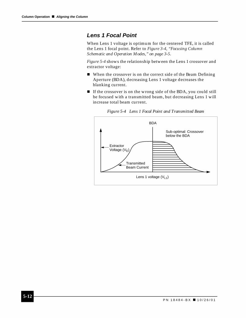
5-12P N 1 8 4 8 4 - B X � 1 0 / 2 6 / 0 1
Column Operation � Aligning the Column
Lens 1 Focal PointWhen Lens 1 voltage is optimum for the centered TFE, it is called the Lens 1 focal point. Refer to Figure 3-4, “Focusing Column Schematic and Operation Modes,” on page 3-5.
Figure 5-4 shows the relationship between the Lens 1 crossover and extractor voltage:
� When the crossover is on the correct side of the Beam Defining Aperture (BDA), decreasing Lens 1 voltage decreases the blanking current.
� If the crossover is on the wrong side of the BDA, you could still be focused with a transmitted beam, but decreasing Lens 1 will increase total beam current.
Figure 5-4 Lens 1 Focal Point and Transmitted Beam
BDA
Sub-optimal: Crossover below the BDA
TransmittedBeam Current
Lens 1 voltage (VL1)
ExtractorVoltage (VE)
5-13P N 1 8 4 8 4 - B X � 1 0 / 2 6 / 0 1
Column Operation � Aligning the Column
Lens Wobbling and Beam Motion Wobbling Lens 1 and Lens 2 voltages changes their focal lengths which changes beam alignment. Changing the focal length will indicate if the beam is off-center or in the center of the lens.
When the beam passes through the center of the lenses, off-axis aberrations and the final spot size are minimized.
Wobbling indicates the following:
� If the beam passes off-axis through the lens, changing the focal length moves the image laterally.
� If the beam passes through the center of the lens, changing the focal length causes the image to go in and out of focus, but the image does not move.
Aligning an Off-Axis Beam
The wobbling technique of varying the lens voltage provides a convenient method of viewing an off-axis beam as an apparent image motion.
To align an off-axis beam with Lens 1 and Lens 2:
1. Adjust the TFE tip position while wobbling Lens 1 to align the TFE to Lens 1.
2. Adjust the steering quadrupoles while wobbling Lens 2 to align the beam to pass through the center of Lens 2.
The beam is properly aligned into a given lens element when there is no lateral translation of the image when that lens voltage is wobbled.
See also
Digital Deflection Controller User’s Guide, PN 95721, Tutorial
5-14P N 1 8 4 8 4 - B X � 1 0 / 2 6 / 0 1
Column Operation � Aligning the Column
Balancing the Stigmating Octupole to the BeamAs you adjust the STIG X and STIG Y controls on the digital deflection controller (DDC), the image of a small spherical object will become elliptical on either side of the correct stigmation setting.
During stigmation adjustment, you want to set the controls between the two points where the sphere becomes elliptical in perpendicular directions. It may be necessary to correct stigmation with each different beam current, i.e., Lens 1 voltage setting.
When you are doing the alignment procedures, remember this information:
� The image “wobbles” if the field is not centered on the beam.
� Astigmatism appears as an off-axis “smearing.”
Column Alignment ChecklistThis checklist shows the sequence of procedures for column alignment and where they are located.
� Coarse Alignment Procedures, 5-15
� Fine Alignment: Lens 1, 5-17
� Fine Alignment: Lens 2, 5-19
Procedures described on the following pages assume the column has been turned on following the procedures of “Initial Turn On” on page 5-8.
See also
Deflection Octupole, 3-11Digital Deflection System User’s Guide,
PN 95721, Tutorial

5-15P N 1 8 4 8 4 - B X � 1 0 / 2 6 / 0 1
Column Operation � Aligning the Column
Coarse Alignment ProceduresPerform coarse alignment for the following conditions:
� A new TFE was just installed.
� The TFE position was changed since the last alignment to the extent that there is no transmitted beam current.
� Initial installation has been completed.
Otherwise, go to “Fine Alignment: Lens 1” on page 5-17.
Finding the BeamThe goal of this part of the course alignment procedures is to find the point of maximum brightness. Do not attempt to achieve image clarity at this time. By finding the point of maximum brightness at each step, the sample will gradually come into focus.
1. Verify that all video detection is turned on and functioning.
2. On the DDC, turn up the contrast until “noise” appears on the raster screen.
3. Turn an opposing pair of source positioner knobs until you see an “image” appear on the screen. Refer to “TFE Positioning” on page 5-11. You are seeking the area of maximum brightness.
� The image usually consists of the screen going from “noise” to bright white. It could also appear as more, brighter noise.
� During this process you will need to reduce the contrast on the raster screen so the image does not saturate the screen.
4. Repeat Step 3 with the second opposing pair of source positioner knobs and achieve maximum brightness for the direction of this set of knobs. Adjust contrast down if image becomes too bright.
5. Switch back to the original set of knobs (from step 3) and verify this location is still the point of maximum brightness.
Continue switching back and forth between directions (between positioner knob sets) and reducing contrast until the point of maximum brightness has been achieved with both sets of positioner knobs.
CA
UT
ION
DO NOT screw the source positioner screws in too far. Torque required to turn the screws increases toward the screw limits. Use this torque as a guide to prevent possible damage to the column.

5-16P N 1 8 4 8 4 - B X � 1 0 / 2 6 / 0 1
Column Operation � Aligning the Column
Focusing the ImageIt is important to be patient! Do not attempt to focus until the point of maximum brightness is achieved for each step of “Finding the Beam” on page 5-15. If maximum brightness is not achieved, the column will be out of alignment and resolution and beam current will be compromised.
To focus the image:
1. On the HVPS’s MUI, select LENS 1. Using the SET knob, slowly turn up the Lens 1 voltage until the image begins to darken.
Initially you should see the image on the raster screen get brighter. The image will reach a point of maximum brightness and then start to darken. Reduce the contrast if the image saturates the screen.
2. Go back to the source positioner knobs on the column and repeat “Finding the Beam” on page 5-15, steps 3–5, and step 1 of Focusing the Image until you achieve focus on your sample. This could take several iterations.
5-17P N 1 8 4 8 4 - B X � 1 0 / 2 6 / 0 1
Column Operation � Aligning the Column
Fine Alignment: Lens 1To center the beam through Lens 1 and achieve 100 nA beam current:
1. Verify that you are focused on your sample. If the image is not focused, adjust Lens 1 voltage on the MUI until a clear image has been achieved.
2. Initially you should see the image on the raster screen get brighter. Using the DDC, set the magnification as high as possible without compromising image detail.
3. Engage the Lens 1 wobble function on the HVPS’s MUI by pressing and holding LENS 1 until its green LED is illuminated.
4. Using the source positioner knobs, (one direction and then the other direction) minimize the wobble of the image that appears on the raster screen.
Lens 1 is aligned when the image moves in and out of focus and does not translate laterally when Lens 1 is wobbled.
You may not be able to completely get rid of the wobble; try to minimize it as best as possible.
5. On the HVPS’s MUI, select BEAM. Using the SET knob, increase beam voltage to 10 kV in 2 kV/minute increments.
While increasing the beam voltages, it will be necessary to adjust Lens 1 voltage to keep the focus on the sample. This will prevent the image from being lost.
6. If the image is lost, reduce the Lens 1 voltage until the image is found and then repeat the “Coarse Alignment Procedures” on page 5-15 followed by the procedures for “Fine Alignment: Lens 1” on page 5-17.
5-18P N 1 8 4 8 4 - B X � 1 0 / 2 6 / 0 1
Column Operation � Aligning the Column
Obtain the Blanking CurrentUse the extractor voltage and Lens 1 voltage to obtain a blanking current of 100 nA.
1. Blank the beam. On the DDC, select BLANK. When it is illuminated, the beam has been blanked and the DDC’s Beam message displays “Blanked.”
2. On the HVPS’s MUI, select EXTRACTOR. Using the SET knob, increase the extractor voltage until the blanked current peaks. Initially this will be somewhere below 100 nA.
3. On the HVPS’s MUI, select LENS 1. Using the SET knob, adjust the Lens 1 voltage until the blanked current peaks.
When adjusting the Lens 1 voltage, you will see that the blanked current increases, goes through a flat plateau where the current remains unchanged, and then starts to decrease. See Figure 5-4, “Lens 1 Focal Point and Transmitted Beam,” on page 5-12.
4. Repeat steps 1 and 2 for adjusting the extractor voltage and Lens 1 voltage until 100 nA of blanked current is achieved.
The goal is to keep the Lens 1 voltage adjusted so the blanking current remains in the plateau. Therefore, if it is adjusted properly, small changes in Lens 1 should have no impact on the blanking current.
5. Unblank the beam. On the DDC, select BLANK. When it is not illuminated, the beam has been unblanked and the Beam message displays “On.”
6. Verify the alignment of the column using the “Coarse Alignment Procedures” on page 5-15 and “Fine Alignment: Lens 1” on page 5-17. Once alignment has been achieved it will be necessary to ensure that the blanking current is still maximized at 100 nA.
7. Increase the beam voltage to 25 kV. Again, it will be necessary to adjust the Lens 1 voltage to keep the image in focus.
8. Verify that the column is still aligned and that maximum blanking current is still 100 nA. Adjust as necessary.
See also
Digital Deflection System User’s Guide,PN 95721
High Voltage Power Supply User’s Guide,PN 19946, Manual User Interface
NO
TE
Adjustments made to the TFE alignment can change the blanked current. Similarly, adjustments made to the extractor voltage can change the alignment. There is a fine line where the two are balanced.
5-19P N 1 8 4 8 4 - B X � 1 0 / 2 6 / 0 1
Column Operation � Aligning the Column
Fine Alignment: Lens 2To center the beam through Lens 2:
1. Blank the beam. Refer to step 1 in “Obtain the Blanking Current” on page 5-18.
2. On the HVPS’s MUI, select LENS 1. Using the SET knob, reduce Lens 1 until the blanking current is at 1 nA. The crossover should now be above the BDA.
3. Unblank the beam. Refer to step 5 in “Obtain the Blanking Current” on page 5-18.
4. On the HVPS’s MUI, select LENS 2. Using the ADJUST knob, increase Lens 2 voltage until you are able to focus on the sample.
5. set magnification (minimum of 1000 X) to focus on a part of the sample that has some detail.
6. Turn on Lens 2 wobble. On the HVPS’s MUI, press and hold LENS 2 until its illuminated green.
7. Minimize the image shift by adjusting the X and Y on the DDC with the following procedure:
� On the DDC, press ADJUST.
� Press TOGGLE until Quad 2 is highlighted.
� Adjust the Quad 2X and Quad 2Y by turning the upper knob and lower knob, respectively.
Lens 2 is aligned when the image moves in and out of focus and does not translate laterally when Lens 2 is wobbled.
8. On the HVPS’s MUI, turn off the Lens 2 wobble by pressing and holding LENS 2 until its LED turns off.
9. Adjust Lens 2 voltage until focus is achieved.
10. Set the magnification to 3,000 X and refocus Lens 2.
11. Adjust Stig X and Stig Y to optimize image sharpness:
� On the DDC, press STIG.
� Adjust Stig X and Stig Y by turning the upper and lower knobs respectively.
12. Refocus Lens 2.
See also
Digital Deflection System User’s Guide,PN 95721
See also
High Voltage Power Supply User’s Guide, PN 19946, Manual User Interface
5-20P N 1 8 4 8 4 - B X � 1 0 / 2 6 / 0 1
Column Operation � Changing Aperture Size
Changing Aperture SizeThe effective aperture, determined by Lens 1, is the half-angle of the solid cone referred back to the source. Since the Lens 1 voltage affects the crossover position, it directly controls the effective aperture. In this arrangement, changes in the effective aperture cause changes to the delivered current. When changing the aperture size consider the following:
� The crossover position within the column is controlled by the Lens 1 voltage.
� The beam transmission through the BDA is dependent upon the crossover location.
� The current delivered to the target is that current which is transmitted through the BDA.
� The delivered target current is controlled by the Lens 1 voltage.
Changing Aperture SizeTo change the aperture size, use Table 5-1 on page 5-23 as an approximate guide for lens voltage adjustments and then perform the following procedures:
1. Blank the beam. Refer to step 1 in “Obtain the Blanking Current” on page 5-18.
2. Adjust the extractor voltage and Lens 1 voltage to obtain the beam current value you desire. Use Table 5-1 as an approximate guide.
On the HVPS’s MUI, select EXTRACTOR for the extractor voltage or select LENS 1 for the Lens 1 voltage. Adjust either with the SET knob.
3. Unblank the beam. Refer to step 5 in “Obtain the Blanking Current” on page 5-18.
4. Focus the image using the LENS 2 control.
5. Correct astigmatism if required. Refer to step 11 of “Fine Alignment: Lens 2” on page 5-19.
6. Construct a table of settings for later reference.
The correct extractor and lens voltage settings for your environment should be determined experimentally.
See also
Electronically Variable Aperture, 3-8
See also
Digital Deflection System User’s Guide,PN 95721
See also
High Voltage Power Supply User’s Guide,PN 19946, Manual User Interface

5-21P N 1 8 4 8 4 - B X � 1 0 / 2 6 / 0 1
Column Operation � Tips for Column Operation
Tips for Column Operation
Beam Diameter and Working Distance The beam diameter increases slowly as the working distance increases. When the working distance increases from 15 to 75 mm, the beam size increases only slightly This allows excellent performance results even at large working distances.
Beam Diameter and Beam VoltageThe beam diameter increases as the beam voltage decreases. Although the focusing column operates over a wide range of beam voltages, the beam voltage significantly affects the beam size. The best performance occurs at the highest beam voltage available.
For optimum resolution, operate the column at the highest beam voltage allowable at the smallest possible working distance.
Beam Diameter and Beam CurrentThe column magnification in conjunction with the effective beam defining aperture (BDA) determines the beam diameter and beam current at a constant working distance. The high chromatic spread of the TFE (and resulting column design) provide a beam diameter that increases when the BDA diameter increases.
Unfortunately, the beam current also decreases as the BDA diameter decreases. The beam current is directly proportional to the square of the aperture diameter.
Smaller effective aperture diameters are necessary for the best image resolution. Larger effective apertures are necessary for higher beam currents. You must decide which of these factors is most important to determine the aperture size (this is usually a compromise).
Field of ViewThe maximum field of view decreases with the increasing beam voltage. The electronics provide a magnification tracking feature to keep the field of view a constant size at a given magnification as the beam voltage changes. Disabling the beam magnification feature permits larger fields of view at voltages < 25 kV.
See also
High Voltage Power Supply Manual User’s Guide, PN 19946
Digital Deflection System User’s Guide, PN 95721
See also
Digital Deflection System User’s Guide,PN 95721
5-22P N 1 8 4 8 4 - B X � 1 0 / 2 6 / 0 1
Column Operation � Full Power Down
Shorting the Blanking Aperture To keep the blanking aperture from charging during operation, keep a picoammeter connected to the blanking aperture BNC or install the shorting connector.
Extractor CurrentPeriodically check the extractor current. Try to maintain the same extractor current and extractor voltage as that used during alignment. Use the controls on the HVPS’s MUI to adjust the suppressor voltage to maintain extractor current and extractor voltage values that maintain the same Lens 1 voltages.
Adjust Video ControlsAdjust the controls on your video screen to achieve the best image (desired brightness, best resolution).
Full Power DownOnce the source is operating at the desired emission level and temperature, we recommend the source not be turned off but left constantly operating. This will keep various column components free of adsorbed gases and the TFE’s emission current stable while maintaining the vacuum in the focusing column.
Perform the following full power down procedures when venting or performing maintenance on the TFE/Lens 1 area of the column:
1. On the HVPS’s MUI, select FILAMENT. Decrease the filament current to 0 A over a one minute period.
2. Select EXTRACTOR. Decrease its voltage to 0 V.
3. Select BEAM. Decrease its voltage to 0 V.
4. Select LENS 1. Decrease its voltage to 0 V.
5. Select LENS 2. Decrease its voltage to 0 V.
6. Select SUPPRESSOR. Increase its voltage to 0 V.
7. Select and hold FIL ENABLE until its LED turns off.
8. Select and hold EHT ENABLE until its LED turns off.
9. Turn off the HVPS and its MUI.
10. Turn off the other electronics.
See also
Installing a Picoammeter, 4-8
See also
High Voltage Power Supply User’s Guide,PN 19946

5-23P N 1 8 4 8 4 - B X � 1 0 / 2 6 / 0 1
Column Operation � Operating Parameters
Operating ParametersParameters listed here are offered as an approximate guide only. Values for your column may vary from this table.
1. This assumes an extractor voltage of 6.0 kV and a working distance of 25mm.
Table 5-1 Column Operating Parameters1
Beam Voltage (kV)
Beam Half Angle (mr)
Beam Current IBEAM (nA)
Lens 1 Voltage VL1 (kV)
Lens 2 Voltage VL2 (kV)
25 0.5 0.39 2.074 13.224
1.0 1.57 2.828 13.364
2.0 6.28 3.295 13.553
4.0 25.1 3.555 13.760
8.0 100 3.694 13.945
10 0.5 0.39 1.354 5.286
1.0 1.57 1.694 5.344
2.0 6.28 1.884 5.420
4.0 25.1 1.987 5.505
8.0 100 2.040 5.579
5 0.5 0.39 1.128 2.642
1.0 1.57 1.339 2.672
2.0 6.28 1.449 2.709
4.0 25.1 1.509 2.751
8.0 100 1.54 2.789
1 0.5 0.39 1.028 0.530
1.0 1.57 1.143 0.536
2.0 6.28 1.208 0.544
4.0 25.1 1.244 0.552
8.0 100 1.263 0.559

P N 1 8 4 8 4 - B X
Chapter 6 User Maintenance
Overview . . . . . . . . . . . . . . . . . . . . . . . . 6-1
Preparing for Maintenance. . . . . . . . . . 6-1Training . . . . . . . . . . . . . . . . . . . . . . . . . . 6-1Tools and Supplies . . . . . . . . . . . . . . . . . 6-1Preparing the Column . . . . . . . . . . . . . . . 6-2
Gasket and O-Ring Replacement . . . . 6-3Replacing Copper Gaskets . . . . . . . . . . . 6-3Replacing and Maintaining O-Rings . . . . 6-4
TFE Replacement . . . . . . . . . . . . . . . . . 6-5Preparation . . . . . . . . . . . . . . . . . . . . . . . 6-5Disconnecting Electronics Cables. . . . . . 6-5Removing the 5-Pin
HV Feedthrough Flange . . . . . . . . . . . . 6-6Removing the
TFE/Suppressor Assembly . . . . . . . . . 6-7Replacing the
TFE/Suppressor Assembly . . . . . . . . . 6-8
Replacing the CIV O-Ring. . . . . . . . . . 6-12Preparation . . . . . . . . . . . . . . . . . . . . . . 6-12Removing the CIV . . . . . . . . . . . . . . . . . 6-12Replacing the O-ring . . . . . . . . . . . . . . . 6-12Replacing the CIV . . . . . . . . . . . . . . . . . 6-13Evacuating the System . . . . . . . . . . . . . 6-13

6-1P N 1 8 4 8 4 - B X � 1 0 / 2 6 / 0 1
6User Maintenance
OverviewThere are four column components that you can replace:
� Copper gaskets
� O-rings
� Thermal field emitter (TFE)
� Column isolation valve (CIV)
Call FEI Beam Tech Customer Service at (503) 726-2800 for maintenance of all other components of the column.
Preparing for Maintenance
Training Only trained personnel should perform maintenance procedures on the 2LE column. Failure to follow these recommendations may result in damage to the column or its components, or may cause degraded performance.
Tools and Supplies
Supplied by UserBefore you begin maintenance, you will need to supply the following items:
� Dry, filtered nitrogen
� Pair of Class 100 powder-free latex rubber gloves
� Aluminum foil (to wrap the column; household type is fine)
� Laminar flow hood (optional, highly recommended)
� Isopropanol
You will also need an assistant to help remove the column from the system.

6-2P N 1 8 4 8 4 - B X � 1 0 / 2 6 / 0 1
User Maintenance � Preparing for Maintenance
Supplied by FEIYou will find the following items in the tool kit supplied with the focusing column:
� 5/64 Allen wrench
� 9/64 Allen wrench
� 1/4 x 5/16 box end wrench
� 8/32 x 1/2 screws (6)
� 5/16-24 hex nut (8)
� 5/16-24 stud (8)
� 5/16 washer (8)
� 1.33-in. oxygen free high conductivity (OFHC) copper gasket (5)
� 2.75-in. copper OFHC gasket (2)
� 4.5-in. copper OFHC gasket (2)
� 4.625-in. copper OFHC gasket (2)
� Braycote (vacuum grease)
� O-ring, 2-010 Viton for CIV (5)
� Pogo pins (5)
Preparing the ColumnTo prepare the 2LE column for user maintenance:
1. Perform the procedure for “Full Power Down” on page 5-22 to turn off the appropriate electronics.
2. Allow half an hour for the TFE to cool down.
3. Vent the focusing column.
4. Remove the high voltage (HV) cable connectors from the column.
5. Using dry, filtered nitrogen, blow all dust particles off the focusing column, source flange, ion pump, specimen chamber, hoses and cables, and miscellaneous components in the immediate vicinity.
6. If the column is to be removed from the vacuum system, ensure that nothing inside the specimen chamber will inhibit the column from moving freely out of its mounting on the chamber.
6-3P N 1 8 4 8 4 - B X � 1 0 / 2 6 / 0 1
User Maintenance � Gasket and O-Ring Replacement
Gasket and O-Ring Replacement
Replacing Copper GasketsCopper gaskets provide vacuum sealing for many of the flanges on the focusing column.
When a copper gasket is installed, it is crushed between two flange surfaces. As it is crushed, it expands and this expansion creates a seal. However, this makes the gasket difficult to remove.
Removing a Copper GasketEach flange that accepts a 4.5-in. or the larger 4.625-in. Conflat copper gasket includes a relief used for gasket removal.
Insert the end of a slotted screwdriver or similar tool in the relief to pry up the old gasket. Never push inward to loosen the gasket.
Installing a Copper GasketAlways install a new copper gasket.
1. Inspect the flange surfaces. If there appears to be contaminants on the mating surfaces, clean the flanges using a lint-free cloth dipped in isopropanol.
2. Set the gasket onto the flange.
3. Before installing the mating flange, ensure the gasket lies flat and is centered.
4. Install the mating flange and tighten securely.
NO
TE A new copper gasket must
be used any time a flange is resealed.
CA
UT
ION
Removing gaskets incorrectly may damage the vacuum sealing knife edge on the Conflat flange. If such damage occurs, return the focusing column to FEI for flange replacement.
6-4P N 1 8 4 8 4 - B X � 1 0 / 2 6 / 0 1
User Maintenance � Gasket and O-Ring Replacement
Replacing and Maintaining O-Rings
O-rings are bands of elastic material used in various column flange locations to form seals between two surfaces.
Inspecting an O-RingInspect an O-ring to see if it is scratched, torn, or has contaminant particles on its surface. If contaminants cannot be cleaned off, replace these O-rings, because air may leak in through the seal and the necessary high vacuum may not be attainable.
Cleaning an O-RingO-rings are only reusable if they remain in like-new condition. If an O-ring has lint, dust, oil, or other contaminants on its surface that can be cleaned off, wet a lint-free cloth with isopropanol, then gently wipe off the contaminants.
Lubricating an O-RingNever apply vacuum grease or other lubricants to any O-ring. If lubrication is necessary to help seat an O-ring, use small amounts of deionized water; the deionized water will later be baked from the system.
6-5P N 1 8 4 8 4 - B X � 1 0 / 2 6 / 0 1
User Maintenance � TFE Replacement
TFE Replacement
PreparationGenerally, the TFE may be replaced without removing the focusing column from the user’s vacuum system.
Before starting the TFE replacement procedures, perform “Full Power Down” on page 5-22.
TFE Replacement Checklist� Disconnecting Electronics Cables, 6-5
� Removing the 5-Pin HV Feedthrough Flange, 6-6
� Removing the TFE/Suppressor Assembly, 6-7
� Replacing the TFE/Suppressor Assembly, 6-8
� Reinstalling the 5-Pin HV Feedthrough Flange, 6-10
� Evacuating the System, 6-11
Disconnecting Electronics CablesRefer to Figure 3-2, “Column Vacuum Chamber, Chamber Window View,” on page 3-2 and Figure 3-3, “Column Vacuum Chamber, CIV view,” on page 3-3 for the following procedures:
1. Turn off the power to the high voltage power supply (HVPS), manual user interface (MUI), and the digital deflection controller (DDC).
2. Remove the four screws holding the 5-pin cable connector and support bracket to the flange.
3. Remove the 5-pin connector and cable straight out from the 5-pin feedthrough.
4. Carefully wrap the 5-pin connector in aluminum foil to keep it free of contaminants. Place it in a secure location.
5. Release the Lens 2 HV cable ground lead that is attached by a screw to the source flange.
6. Remove the Lens 2 HV cable by unscrewing the black protective cover from the ceramic feedthrough and pulling out the cable. Place the Lens 2 HV cable in a secure location.
7. Disconnect the 20 multipin connector attached to the 20-pin deflection feedthrough on the column by unscrewing the outer ring and pulling out the connector.
CA
UT
ION The TFE tip protrudes from
the top of the suppressor:n Do not touch the tip. n Wear Class 100 clean
room gloves during TFE replacement.
CA
UT
ION
Do not touch the ends of the connectors (the portions that slip inside the HV feedthrough) as any dirt, oils, or other contaminants on the connector may cause high voltage breakdown.
6-6P N 1 8 4 8 4 - B X � 1 0 / 2 6 / 0 1
User Maintenance � TFE Replacement
Removing the 5-Pin HV Feedthrough FlangeRefer to Figure 4-3, “Column Vacuum Chamber, Chamber Window View,” on page 4-7 for these procedures:
1. Unbolt the 4.625-in. Conflat flange connected to the 5-pin HV feedthrough flange, using the 1/4 x 5/16 box end wrench.
2. Loosen the flange. The feedthrough flange may be difficult to loosen after the bolts are taken off. If this is the case, pry the flanges apart using a slotted screwdriver inserted into the recessed hole in the focusing column flange.
3. Remove the flange. Put on cleanroom gloves and grasp the feedthrough flange. Lift the flange straight up and off the focusing column.
Be careful to clear the pogo pins inside the column as the feedthrough is raised.
4. Carefully set the feedthrough on a flat, clean surface where it will be safe from damage during other operations.
5. Remove the copper gasket. Refer to “Gasket and O-Ring Replacement” on page 6-3.
6. Cover the vacuum side surface of the feedthrough with clean aluminum foil.

6-7P N 1 8 4 8 4 - B X � 1 0 / 2 6 / 0 1
User Maintenance � TFE Replacement
Removing the TFE/Suppressor AssemblyLook into the top of the column. The two wide arms that look like paddles are the suppressor clamps. The two long, thin arms are the TFE filament contacts.
1. Remove the five pogo pins by pulling them straight out of the receptacle.
2. See Figure 6-1. Using the 5/64 Allen wrench supplied with the tool kit, loosen (but do not remove) the suppressor clamp and filament contact screws just enough to allow the suppressor clamps to swing away from the suppressor assembly and the filament contacts to swing away from the TFE filament posts. See Figure 6-2, “TFE/Suppressor Assembly (during replacement),” on page 6-8.
3. Firmly grasp the filament posts with a pair of needle nose pliers or strong forceps and lift the TFE/suppressor assembly straight out of the insertion socket.
Figure 6-1 TFE/Suppressor Assembly before Removal
Pogo Pins
Suppressor Clamps
Filament Contacts
Wire Lead
Pogo Pins
Conflat Flange
Suppressor Clamps
Filament Contacts
Pogo Pins
CA
UT
ION The TFE tip is quite fragile.
Do not allow the tip to contact any surface or it will be destroyed.

6-8P N 1 8 4 8 4 - B X � 1 0 / 2 6 / 0 1
User Maintenance � TFE Replacement
4. Place the TFE/suppressor assembly in a safe location for the next operation.
Replacing the TFE/Suppressor AssemblyWhen first shipped from FEI, the TFE is preinstalled in the suppressor assembly and shipped in a plastic container with its unique Schottky Test Data Sheet.
Each data sheet contains the filament current data for operating the source at 1800 K at FEI’s test center. It is recommended that you add 80 mA to the data sheet value to approximate the heating current value you need for operation at 1800 K.
Unpacking the TFE/suppressor Assembly1. To open the TFE/suppressor assembly shipping container, set
its black base on a clean flat surface (the FEI logo should be facing upward).
2. Hold the black base down firmly and slowly twist off the clear top.
3. Loosen the two clamping screws on the black base to release the TFE/suppressor assembly.
4. Wearing cleanroom gloves, lift the TFE/suppressor assembly straight up from the base. The tip of the TFE protrudes from the hole on the top of the suppressor.
Figure 6-2 TFE/Suppressor Assembly (during replacement)
Filament Posts
FilamentContacts
Wire Lead
Suppressor Clamps
Suppressor Clamps
FilamentContacts
NO
TE
Refer to “TFE Calibration Sheet” on page 5-2 for information about adding 80 mA to the data sheet heating current value to operate at 1800 K.The filament current needed to heat the cathode to 1800 K will be different for each source, so it is important to keep this data sheet with the column for reference during the start up procedure.
CA
UT
ION
Do not jerk the container while opening it or the TFE may be damaged.
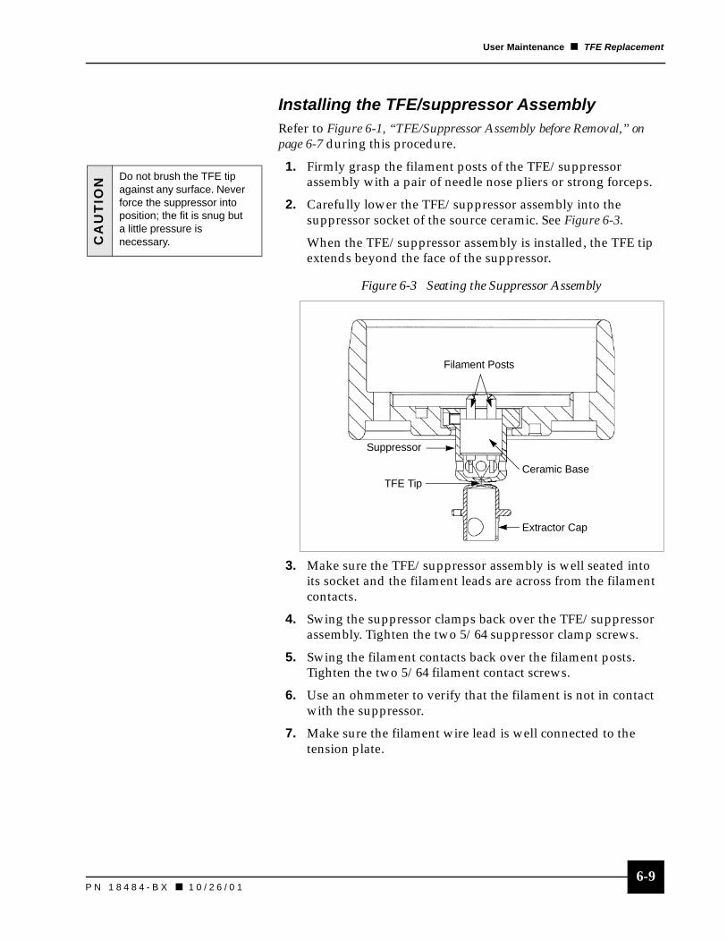
6-9P N 1 8 4 8 4 - B X � 1 0 / 2 6 / 0 1
User Maintenance � TFE Replacement
Installing the TFE/suppressor AssemblyRefer to Figure 6-1, “TFE/Suppressor Assembly before Removal,” on page 6-7 during this procedure.
1. Firmly grasp the filament posts of the TFE/suppressor assembly with a pair of needle nose pliers or strong forceps.
2. Carefully lower the TFE/suppressor assembly into the suppressor socket of the source ceramic. See Figure 6-3.
When the TFE/suppressor assembly is installed, the TFE tip extends beyond the face of the suppressor.
3. Make sure the TFE/suppressor assembly is well seated into its socket and the filament leads are across from the filament contacts.
4. Swing the suppressor clamps back over the TFE/suppressor assembly. Tighten the two 5/64 suppressor clamp screws.
5. Swing the filament contacts back over the filament posts. Tighten the two 5/64 filament contact screws.
6. Use an ohmmeter to verify that the filament is not in contact with the suppressor.
7. Make sure the filament wire lead is well connected to the tension plate.
Figure 6-3 Seating the Suppressor Assembly
CA
UT
ION Do not brush the TFE tip
against any surface. Never force the suppressor into position; the fit is snug but a little pressure is necessary.
Filament Posts
Suppressor
Ceramic Base
Extractor Cap
TFE Tip
6-10P N 1 8 4 8 4 - B X � 1 0 / 2 6 / 0 1
User Maintenance � TFE Replacement
8. Replace all pogo pins by inserting them straight down into the receptacle.
Gently exercise the pogo pin inner spring to verify that it is not damaged. It should have full range of travel and not stick. If damaged, replace with a new pogo pin.
9. Use an ohmmeter to verify that the filament contacts are making contact with the filament posts.
10. If the filament contacts are not making good contact, swing the filament contacts away from the posts, press down to bend contacts, and swing back over posts. Tighten and use an ohmmeter to verify.
Reinstalling the 5-Pin HV Feedthrough Flange1. Clean the 4.625-in. Conflat flange knife edge so it is free of
grease and lint.
2. Install a new copper gasket onto the 4.625-in. flange of the chamber.
3. Remove the aluminum foil covering the 5-pin feedthrough flange.
4. Clean the specimen chamber vacuum sealing surface and the flange sealing surface with a lint-free cloth and isopropanol.
5. Note the asymmetry of the pin configuration of the high voltage connectors in Figure 6-4. The two filament pins are separated from the Lens 1 pin, extractor pin, and suppressor pin.
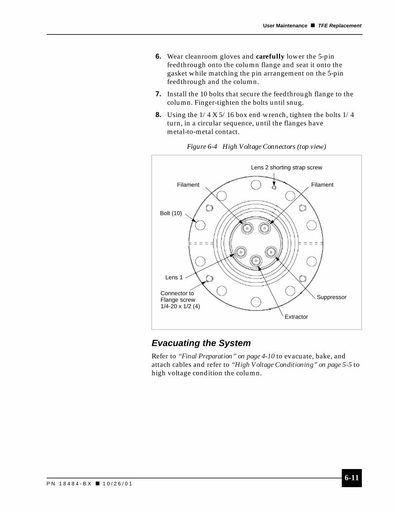
6-11P N 1 8 4 8 4 - B X � 1 0 / 2 6 / 0 1
User Maintenance � TFE Replacement
6. Wear cleanroom gloves and carefully lower the 5-pin feedthrough onto the column flange and seat it onto the gasket while matching the pin arrangement on the 5-pin feedthrough and the column.
7. Install the 10 bolts that secure the feedthrough flange to the column. Finger-tighten the bolts until snug.
8. Using the 1/4 X 5/16 box end wrench, tighten the bolts 1/4 turn, in a circular sequence, until the flanges have metal-to-metal contact.
Evacuating the SystemRefer to “Final Preparation” on page 4-10 to evacuate, bake, and attach cables and refer to “High Voltage Conditioning” on page 5-5 to high voltage condition the column.
Figure 6-4 High Voltage Connectors (top view)
Connector to Flange screw1/4-20 x 1/2 (4)
FilamentFilament
Bolt (10)
Suppressor
Extractor
Lens 1
Lens 2 shorting strap screw
6-12P N 1 8 4 8 4 - B X � 1 0 / 2 6 / 0 1
User Maintenance � Replacing the CIV O-Ring
Replacing the CIV O-RingThis procedure may be performed while the column remains on your vacuum system. Before replacing the CIV O-ring, perform the “Full Power Down” on page 5-22.
Preparation1. Vent the column and vacuum system to standard atmosphere.
2. Disconnect the pressurized air line that feeds the CIV actuator.
Removing the CIV1. Using the 9/64 right-angle Allen wrench, remove the six
screws of the mini-Conflat flange of the CIV actuator mechanism.
2. Gently slide out the CIV actuator and its actuation arm. Move them straight out until the entire CIV assembly has cleared the mounting flange.
3. Remove the copper gasket from the mini-flange. Refer to “Gasket and O-Ring Replacement” on page 6-3.
Replacing the O-Ring1. The sealing O-ring is visible on the end of the actuator arm.
� Remove the O-ring. Be careful to not damage the end of the actuator arm. Do not try to reuse this particular O-ring. You have to destroy it to remove it.
� Remove any particulates with clean pressurized air and clean the end of the actuator arm with isopropanol.
2. Seat the new O-ring onto the arm and place a new copper gasket onto the mini-flange.
CA
UT
ION
Take care when removing the actuator arm from the chamber. There are four lubricating pads that have been glued to the arm of the CIV that may fall off if the CIV is not removed carefully.n If the pads fall off, they
will need to be reglued.
n Contact FEI to order the correct glue.

6-13P N 1 8 4 8 4 - B X � 1 0 / 2 6 / 0 1
User Maintenance � Replacing the CIV O-Ring
Replacing the CIV1. Carefully insert the actuator arm through the access port and
into the internal CIV body.
2. Install the six screws of the mini-Conflat flange. Tighten in a circular sequence, making sure to obtain metal to metal contact.
3. Reconnect the pressurized air line.
Evacuating the SystemRefer to “Final Preparation” on page 4-10 to evacuate, bake, and attach cables and refer to “High Voltage Conditioning” on page 5-5 to high voltage condition the column.
CA
UT
ION
Make sure the plastic sliding pads remain in place and that the orientation is such that the pointed end of the arm is on the side opposite the source end of the column.

P N 1 8 4 8 4 - B X
Chapter 7 Troubleshooting
Overview . . . . . . . . . . . . . . . . . . . . . . . . 7-1
Electronics. . . . . . . . . . . . . . . . . . . . . . . 7-1Column Electronics . . . . . . . . . . . . . . . . . 7-1Trips and Interlocks . . . . . . . . . . . . . . . . . 7-2
Image . . . . . . . . . . . . . . . . . . . . . . . . . . . 7-2Hot Shotting . . . . . . . . . . . . . . . . . . . . . . 7-4
Vacuum . . . . . . . . . . . . . . . . . . . . . . . . . 7-5


7-1P N 1 8 4 8 4 - B X � 1 0 / 2 6 / 0 1
7Troubleshooting
OverviewThis chapter provides a guide for troubleshooting problems with the focusing column. Possible problems with the column fall into three categories:
� Electronics
� Image
� Vacuum
Electronics
Column Electronics
Table 7-1 Column Electronics Troubleshooting
Problem Action
Power won’t turn on. Inspect the AC cords for secure installation. Reseat if necessary.
Inspect the AC cords for fraying/damage. Replace if necessary.
Inspect the fuse on the unit. Replace if needed.
High voltage (HV) on. high voltage power supply (HVPS) shut off during operation.
Inspect the vacuum to see if vacuum interlock is connected. If it is not connected, reconnect it.
Inspect fiber optic connection to the HVPS’s MUI. Replace if damaged.
HVPS will not turn on. The HVPS’s power switch is not on. Turn on the power switch.
The vacuum interlock condition is not satisfied.
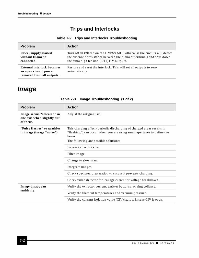
7-2P N 1 8 4 8 4 - B X � 1 0 / 2 6 / 0 1
Troubleshooting � Image
Trips and Interlocks
Image
Table 7-2 Trips and Interlocks Troubleshooting
Problem Action
Power supply started without filament connected.
Turn off FIL ENABLE on the HVPS’s MUI; otherwise the circuits will detect the absence of resistance between the filament terminals and shut down the extra high tension (EHT) HV outputs.
External interlock becomes an open circuit, power removed from all outputs.
Restore and reset the interlock. This will set all outputs to zero automatically.
Table 7-3 Image Troubleshooting (1 of 2)
Problem Action
Image seems “smeared” in one axis when slightly out of focus.
Adjust the astigmatism.
“Pulse flashes” or sparkles in image (image “noise”).
This charging effect (periodic discharging of charged areas results in “flashing”) can occur when you are using small apertures to define the beam. The following are possible solutions:
Increase aperture size.
Filter image.
Change to slow scan.
Integrate images.
Check specimen preparation to ensure it prevents charging.
Check video detector for leakage current or voltage breakdown.
Image disappears suddenly.
Verify the extractor current, emitter build up, or ring collapse.
Verify the filament temperatures and vacuum pressure.
Verify the column isolation valve (CIV) status. Ensure CIV is open.

7-3P N 1 8 4 8 4 - B X � 1 0 / 2 6 / 0 1
Troubleshooting � Image
Image lacks sharpness. Adjust the focus.
Install a shorting plug on all beam current monitoring Bayonet Neil-Concelman (BNC) connectors.
Increase beam voltage.
Decrease working distance.
Adjust astigmatism.
Align lenses and TFE.
Inspect the specimen preparation to ensure it prevents charging.
Inspect the specimen mounting. A loose mount may cause specimen vibration.
Inspect the specimen for contamination.
Decrease beam current.
Verify the extractor current.
Examine the TFE; the emitter may be arced.
Image is distorted. Inspect to ensure proper specimen preparation and grounding to reduce charging.
Inspect the specimen mounting. A loose mount may cause specimen vibration.
Test grounding for electrical interference in the system.
Brightness is low or unstable.
Verify the filament current.
Perform alignment procedure.
Change the TFE.
Try hot shotting the emitter. Refer to “Hot Shotting” on page 7-4.
Image position drifts. Ensure that the specimen is grounded.
Check temperature stability of the room.
Ensure that the specimen and stage are not charging.
The beam will drift if electric fields near the sample change with time. Inspect the secondary electron detector or stage bias for voltage drift.
Table 7-3 Image Troubleshooting (2 of 2)
Problem Action

7-4P N 1 8 4 8 4 - B X � 1 0 / 2 6 / 0 1
Troubleshooting � Image
Hot ShottingUse this procedure when you suspect the emitter has become contaminated.
1. Record these current operating settings:
� Extractor
� Suppressor
� Filament current
� Beam voltage
2. Increase the filament current by 0.040 A.
3. Observe the beam current for 15 minutes. If the emitter is contaminated, the beam current will rise.
4. Turn the filament current back to the original value and wait for the beam current to stabilize.
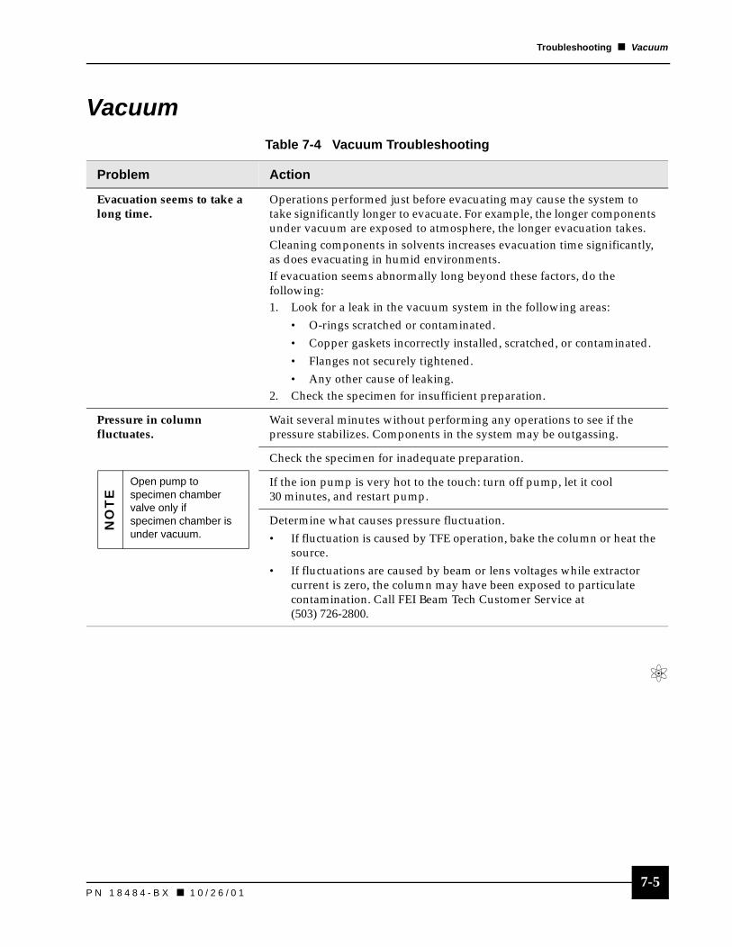
7-5P N 1 8 4 8 4 - B X � 1 0 / 2 6 / 0 1
Troubleshooting � Vacuum
VacuumTable 7-4 Vacuum Troubleshooting
Problem Action
Evacuation seems to take a long time.
Operations performed just before evacuating may cause the system to take significantly longer to evacuate. For example, the longer components under vacuum are exposed to atmosphere, the longer evacuation takes. Cleaning components in solvents increases evacuation time significantly, as does evacuating in humid environments.If evacuation seems abnormally long beyond these factors, do the following:1. Look for a leak in the vacuum system in the following areas:
• O-rings scratched or contaminated.• Copper gaskets incorrectly installed, scratched, or contaminated.• Flanges not securely tightened.• Any other cause of leaking.
2. Check the specimen for insufficient preparation.
Pressure in column fluctuates.
Wait several minutes without performing any operations to see if the pressure stabilizes. Components in the system may be outgassing.
Check the specimen for inadequate preparation.
If the ion pump is very hot to the touch: turn off pump, let it cool 30 minutes, and restart pump.
Determine what causes pressure fluctuation.• If fluctuation is caused by TFE operation, bake the column or heat the
source.• If fluctuations are caused by beam or lens voltages while extractor
current is zero, the column may have been exposed to particulate contamination. Call FEI Beam Tech Customer Service at (503) 726-2800.
NO
TE
Open pump to specimen chamber valve only if specimen chamber is under vacuum.


A-1P N 1 8 4 8 4 - B X � 1 0 / 2 6 / 0 1
Appendix A
Technical ArticlesThe following articles provide in depth background information on the Thermal Field Emitter (TFE) and the Two Lens Electron Column. These articles are recommended for those users who would like additional information on these subjects. Call FEI Beamtech/Marketing at (503) 844-2520 or e-mail us at: [email protected] to order copies of these articles.
Orloff, J. and Swanson, L. W. April 1979. “An Asymmetric Electrostatic Lens for Field-Emission Microprobe Applications.” Reprinted from Journal of Applied Physics: 2494-2501.
Swanson, L. W. Rev. January 1989. “A Comparison of Schottky and Cold Field Emission Cathodes.”
Tuggle, D. W. and Swanson, L. W. January/February 1985. “Emission Characteristics of the ZRO/W Thermal Field Electron Source.” Reprinted from Journal of Vacuum Science and Technology B: 220-223.

G-1P N 1 8 4 8 4 - B X
Glossary
Aabsorption: the penetration of substances into the bulk of a solid or liquid. See adsorption, desorbtion.
adsorption: the surface retention of solid, liquid, or gas molecules, atoms, or ions by a solid or liquid. See absorption, desorbtion.
Automatically Variable Aperture (AVA): automatically adjusts the effective Beam Defining Aperture to vary the beam current and arrive at the effective aperture size desired.
BBeam Acceptance Aperture (BAA): accepts the central portion of the electron beam for subsequent focusing in the Beam Defining Aperture (BDA).
beam blanking: refers to sweeping the beam into a Faraday cup for measuring rather than allowing it to hit the sample surface. On the electron column, beam blanking redirects the electron beam away from the sample, but is not measured. When a beam is blanked, you can’t image.
beam current: the amount of electron current striking the specimen; current measured from blanking aperture Faraday cup.
Beam Defining Aperture (BDA): limits the beam current to define the size of the beam; a physical aperture located in the optical path of the column. See effective aperture.
beam diameter: column parameters. Also known as spot size.
beam voltage: accelerating voltage of the electrons.
black body: an ideal body which would absorb all incident radiation and reflect none.
blanking aperture: an opening in the column that enables beam diversion.
BNC connector (Bayonet Neil-Concelman): a small device for connecting coaxial cable.

G-2 P N 1 8 4 8 4 - B X
Glossary � C
Ccathode: Schottky emission source; see Thermal Field Emitter (TFE).
chromatic aberration: phenomena caused by electrons of different energy levels passing through the lenses where off-axis slower electrons tend to focus at a shorter focal point.
CIV: see Column Isolation Valve.
column: See electron focusing column.
column isolation valve (CIV): when closed, isolates the vacuum levels of the source/Lens 1 region from the Lens 2/specimen chamber area. When open, the beam passes through the differential pumping aperture (DPA) in the valve and enters the lower half of the column and specimen chamber.
Ddesorbtion: the process of removing a sorbed substance by the reverse of adsorption or absorption. See absorption, adsorption.
Differential Pumping Aperture (DPA): in combination with the ion pump, ensures adequate vacuum in the focusing column.
Eearth: see ground.
effective aperture: determined by Lens 1; the half-angle of the solid cone referred back to the source.
electron focusing column: the electrostatic lenses that focus the electron beam.
Electronically Variable Aperture (EVA): electronically adjusts the effective BDA to vary the beam current and arrive at the effective aperture size desired.
emissivity: the ratio of the radiation emitted by a surface to the radiation emitted by a perfect black body radiator at the same temperature. Also known as thermal emissivity.
emission current: the electron beam current emitted from the source.
emitter: a substance or electrode that emits particles; see Thermal Field Emitter (TFE).
extractor current: the amount of current removed from total emission current by the extractor cap. For practical purposes, this is the same as the term emission current.

G-3P N 1 8 4 8 4 - B X
Glossary � F
extractor voltage: The voltage applied to the extractor electrode in the electron or ion gun. Application of the extractor voltage results in emission of particles from the source. An increase in extractor voltage will increase emission current.
FFaraday cup: a device used to collect particles of beam current for subsequent measurement.
field of view: the area of the specimen visible on the video monitor; varies with magnification levels.
focusing column: See electron focusing column.
Gground (noun): a conducting path between an electric circuit or equipment and the earth; also known as earth.
ground (verb): to connect electrical equipment to the earth or to some conducting body that serves in place of the earth.
Hhigh tension (HT): synonym for high voltage; anything over 30 volts.
high voltage (HV): anything over 30 volts.
High Voltage Power Supply: supplies the focusing column with source heating, source extraction and suppression voltages, beam voltage and focusing voltages.
IIGP (Ion Getter Pump): ultra high vacuum pump that maintains the source emission chamber at low enough pressure to prevent oxidation of the source due to its operation at high temperature; an entrapment pump. This type produces vacuum by ionizing gas molecules and accelerating them towards titanium plates, in which they become implanted.
LLED: Light Emitting Diode
lens align: adjustment of the final lens of the electron beam for aperture alignment.
G-4 P N 1 8 4 8 4 - B X
Glossary � M
MMUI (Manual User Interface): a hardware device that allows you to use knobs and buttons for some functions.
MSDS (Material Safety Data Sheet): a form from the manufacturer that supplies chemical product composition, hazards, and other safety information.
0octupole deflector: physical deflectors with 8 poles or plates each that deflect and correct stigmation of the electron beam while it passes through the end of the column.
optical column: the metal structure containing the source and the electron focusing elements. See electron focusing column.
Qquadrupole: physical deflector with 4 poles or plates each that center the beam while it passes through the column.
Rraster scan: a left-to-right, top-to-bottom (X,Y) movement of the beam. This series of lines is shifted slightly from one axis to the other. A raster, while appearing continuous, consists of as many as one million individual locations (pixels) that the beam visits.
roughing pump: A positive displacement pump used for rough pumping of the specimen chamber, electron column, and ion column and electron column and ion column during initial pumpdown. The roughing pump produces vacuum by means of displacement of trapped volumes of gas, typically by sliding vanes or intermeshing rotating lobes.
Ssecondary electrons: particles leaving the specimen surface after the electron beam strikes it.
source: See Thermal Field Emitter (TFE).
specimen: also known as sample, the item to be imaged.
spherical (geometric) aberration: beam perturbations caused by the non-ideal shape of the lens fields and elements.
sputter rate: removal rate for material under the electron beam or deposition rate for metal deposition.
stigmation: the act of removing any astigmatism (shape irregularities) from the beam.
G-5P N 1 8 4 8 4 - B X
Glossary � T
stigmator: adjusts the shape of the beam by applying voltages to plates in the octupole of the focusing column.
suppressor: an electric field that provides control of total extracted current without affecting the beam energy.
TThermal Field Emitter (TFE): electron source using a zirconium oxide coated tungsten (ZrO/W) emitter.
Wwobbler: slowly changes the amplitude, around a preset level, of Lens 1 or Lens 2 voltage to allow for proper beam alignment.
working distance: the distance from the nose cone of the focusing column to the specimen surface; standard working distance is 25 mm.


I-1P N 1 8 4 8 4 - B X � 1 0 / 2 6 / 0 1
Index
AAC power, connection checklist 4-9alignment
background 5-11center of the lens 5-13checklist 5-14column 5-10 – 5-19course alignment 5-15 – 5-16fine alignment
Lens 1 5-17 – 5-18Lens 2 5-19
focusing the beam 5-16goals 5-10Lens 1 crossover 5-12maximum brightness 5-15off-axis beam 5-13overview 5-10positioner knobs 5-11stigmating octupole 5-14TFE positioning 5-11wobbling Lens 1 and Lens 2 5-13
aperturechanging size 5-20effective aperture 5-20
automatically variable aperture (AVA)defined G-1function 1-1
Bbakeout 4-10 – 4-12band heaters 4-11Bayonet Neil-Concelman (BNC)
beam current monitoring connector 3-10blanking the beam 3-10
beamcrossover position 3-9current 5-21
during alignment 5-17diameter 5-21voltage 5-21
beam acceptance aperture (BAA) 3-7beam blanking
assembly 3-10 – 3-11defined G-1during alignment 5-18Faraday Cup 3-11
beam defining aperture (BDA) 3-9blanking aperture
defined G-1keep from charging 5-22
blanking the beam, see beam blanking
BNC, see Bayonet Neil-Concelman (BNC)
Ccable safety, see safety, cords/cablecaution
5-pin HV feedthrough 4-1AC power 4-9bakeout wrapping 4-11CIV
compressed air 4-10high pressure damage 5-7locked-open 5-6removing 6-12
column exposure 4-1column shield 4-1course alignment 5-15gasket replacement 6-3ground loops 4-9handling 4-1installation 4-1installing the TFE/suppressor assembly 6-9operating pressure 5-1O-ring replacement, CIV 6-13performance care 4-1power on 4-1preparing sealing surfaces 4-1pressure burst 5-6storing 4-1TFE
cable connectors 6-5damage 6-8fragility 3-4heat damage 5-2tip 6-5, 6-7
turn on pressure 5-9chemicals 2-7CIV, see column isolation valvecolumn
alignment, see alignmentaperture size, see aperturebakeout, see bakeoutchemicals 2-7cords/cables, see safety, cords/cableenvironment 2-1, 2-8evacuating, see bakeoutexternal features 3-2general operation 1-2ground, see groundhandling 2-1heating, see bakeouthigh voltage conditioning, see high voltage

I-2I-2P N 1 8 4 8 4 - B X � 1 0 / 2 6 / 0 1
Index � D-H
conditioninginstallation, see installationinterlocks 2-5, 5-1internal design 3-4maintenance, see maintenanceoperating parameters 5-23operating tips 5-21 – 5-22operation overview 5-1power down 5-22preinstallation tools and items 4-2sealing surface preparation 4-3shield 4-1startup checklist 5-2storage 2-2subsystems 3-1technical articles A-1training requirements, see trainingturn on, see turn onvacuum chamber 3-2 – 3-3vacuum level 4-12
column isolation valve (CIV)defined G-2differential pumping aperture (DPA) 3-9interlocks 5-1location 3-9operating
closed 5-7locked-open 5-7unlocked-open 5-7
cord safety, see safety, cords/cablecorrosion precautions 2-8
Ddifferential pumping aperture (DPA) 3-9Digital Deflection Controller (DDC)
function 3-13ground 4-8installation 4-8
DPA, see differential pumping aperture
Eearth, see groundelectronically variable aperture (EVA) 3-8electronics 3-13emission current
affects on pressure 5-4calibration 5-2defined G-2during power down 5-22fluctuations 5-4limited by suppressor assembly 3-7
evacuating the column 4-11external features, see column 3-2extractor
assembly 3-7current 5-22current, defined G-2voltage, defined G-3
FFaraday Cup 3-11field of view 5-21fuse, see safety
Ggloves, see safetyground
caution 4-9defined G-3ground loops 4-5hazard symbol 2-3protocol 4-5safety 2-7
Hhazard symbols
Attention 2-3Caution 2-3Danger 2-3Magnetic Field 2-3Protective ground 2-3
high tension (HT)defined G-3troubleshooting 7-2
high voltageconditioning
beam voltage 5-5Lens 2 voltage 5-6operating the CIV 5-7overview 5-5
defined G-3warning symbol 2-3
High Voltage Power Supply (HVPS)connector orientation 4-7function 3-13ground 4-6installation 4-6 – 4-7interlocks 3-13, 5-1safety 2-5shorting strap 4-6ventilation 2-8
I-3P N 1 8 4 8 4 - B X � 1 0 / 2 6 / 0 1
Index � I-S
IIGP (Ion Getter Pump)
connection flange, examples 3-2, 3-3defined G-3installation 4-4interlock circuitry 4-10, 5-7pumping of the source 3-9setting the filament current 5-9
installationbakeout 4-10column 4-3Digital Deflection Controller (DDC), see Digital
Deflection Controller (DDC)final preparation 4-10 – 4-12grounding 4-5High Voltage Power Supply (HVPS), see High
Voltage Power Supply (HVPS)ion vacuum pump, see IGPpicoammeter, see picoammeterpower connection checklist 4-9tools 4-2
interlocks see safetyHigh Voltage Power Supply, see
High Voltage Power Supply (HVPS)internal feature, see columnIon Getter Pump (IGP), see IGP
Llens assemblies 3-8
Mmagnetic shield 3-3maintenance
by the user 6-1 – 6-13CIV O-ring replacement 6-12FEI Beam Tech Customer Service 6-1O-ring 6-4overview 6-1preparation 6-1 – 6-2replacing copper gaskets 6-3TFE replacement 6-5 – 6-11
checklist 6-5disconnecting cables 6-5preparation 6-5removing the high voltage flange 6-6removing the TFE/suppressor
assembly 6-7 – 6-8replacing the TFE/suppressor
assembly 6-8 – 6-11tools and supplies 6-1 – 6-2
training 6-1MSDS (Material Safety Data Sheet)
chemical safety 2-7defined G-4
MUI (Manual User Interface)defined G-4for the HVPS 3-13
NNitrogen, see safety
Ooctupole, stigmating 3-11 – 3-12
Ppicoammeter
installation 4-8measuring blanking current 4-12
power down 5-22power, see safetypreinstallation, see columnpyrometer, temperature adjustment 5-3
Qquadrupole location 3-8
Ssafety
chemicals 2-7column electronics 2-4cords/cables 2-6corrosion 2-8cover panels 2-7environment 2-1fans, electric 2-8fuses 2-7gloves 2-1grounding 2-7handling 2-1High Voltage Power Supply (HVPS) 2-5interlocks 2-5line voltage 2-6main power 2-6maximum vacuum pressure 2-2Nitrogen 2-7symbols 2-3terms 2-3test leads 2-6voltage hazard 2-5voltage levels 2-5
Schottky Emitter Test Data calibration sheet, see

I-4I-4P N 1 8 4 8 4 - B X � 1 0 / 2 6 / 0 1
Index � T-W
thermal field emitter (TFE), calibration sheetsealing surface preparation 4-3shift X and Y 3-12startup checklist, see columnstigmation
adjustment 5-14defined G-4regulated by the DDC 3-13
stigmator field 3-12suppressor, see TFE/suppressor assembly
Ttechnical articles A-1test leads, see safetyTFE, see thermal field emitterTFE/suppressor assembly
emission current 3-7replacement, see maintenancevoltage 3-4
thermal field emitter (TFE)alignment, see alignmentCaution message, fragile 3-4endform equilibrium 5-4extraction current 5-4heating 5-2 – 5-3
calibration sheet 5-2current setting 5-3measuring temperature 5-3operating temperature 5-2
installation vacuum level 4-12maintaining equilibrium 5-4operating variables 3-4positioner knobs 5-11replacement, see maintenancesource region parameters 3-4suppressor voltage 5-3technical articles A-1
tool kit 4-2training requirements
for maintaining 2-4for operating 2-4for servicing 2-4
troubleshooting 7-1 – 7-5electronics 7-1 – 7-2hot shotting 7-4image 7-2 – 7-3vacuum 7-5
turn oncolumn procedures 5-8out gassing 5-9pressure burst 5-9
pressure rise 5-9Schottky Emitter Test Data sheet 5-9setting the extractor voltage 5-9setting the filament current 5-9TFE current 5-9
Vventilation 2-8video controls 5-22voltage hazard, see safety 2-5voltage, see safety 2-6
Wwarning
high voltage 4-6High Voltage Power Supply (HVPS) 3-13, 4-6lethal voltages 2-5Nitrogen asphyxiation 2-7overriding interlocks 2-5
wobble, Lens 1 5-17working distance 5-21