twin compressor compact heat pump t n installation and ... · commissioning’ service, offered...
TRANSCRIPT

Twin Compressor Compact Heat Pump Manual Version 13.25 Page 1 of 42
Twin Compressor Compact Heat Pump
Installation and Commissioning Manual
W
arra
nty
Fa
ult
Fin
din
g C
om
mis
sio
nin
g In
stal
lati
on
el
ectr
ical
In
stal
lati
on
m
ech
anic
al
Inst
alla
tio
n
sch
emat
ics
Inst
alla
tio
n
Gen
era
l pro
du
ct
info
rmat
ion
Sa
fety
info
rmat
ion
In
tro
du
ctio
n
Hea
t P
um
p
sett
ings
sh
eet
Copyright ©2016 Kensa Heat Pumps Ltd
Manual
Twin Compressor Compact Heat Pump Manual Version 13.25 Page 2 of 42
Contents Page
Section Description Page
1....................... Introduction .................................................................................. 4
2....................... Safety Information ........................................................................ 5
2.1........................... Access ...................................................................................................................... 5
2.2........................... Lighting .................................................................................................................... 5
2.3........................... Tools and consumables ........................................................................................... 5
2.4........................... Handling ................................................................................................................... 5
2.5........................... Residual hazards ...................................................................................................... 5
2.6........................... Freezing ................................................................................................................... 5
2.7........................... Disposal/decommissioning ...................................................................................... 5
3....................... General product information ........................................................ 6
3.1........................... Equipment delivery and handling ............................................................................ 6
3.2........................... Kensa Compact technical data ................................................................................. 7
4....................... Installation.................................................................................... 8
4.1........................... The Golden Rules of installing a heat pump ............................................................ 8
4.2 .......................... Underfloor heating schematics ............................................................................... 8
4.2.1........................ Underfloor with a single manifold. Space heating only ........................................... 9
4.2.2........................ Underfloor with multiple manifolds. Space heating only ........................................ 9
4.3........................... Radiators. Space heating only ................................................................................. 10
4.4........................... Domestic Hot Water - Schematic ............................................................................ 10
4.4.1........................ Type of DHW tank ................................................................................................... 11
4.4.2........................ DHW tank size ......................................................................................................... 11
4.4.3........................ Immersion heater .................................................................................................... 11
4.4.4........................ Three Port Diverting Valve ...................................................................................... 11
4.4.5........................ Tank Thermostat ...................................................................................................... 11
4.4.6........................ DHW Timeclock ....................................................................................................... 11
4.4.7........................ Secondary Returns................................................................................................... 11
4.5........................... Mechanical Installation ........................................................................................... 14
4.5.1........................ Locating the Heat Pump .......................................................................................... 14
4.5.2........................ Recommended Clearances ...................................................................................... 14
4.5.3........................ Installation of the heat pump .................................................................................. 15
4.5.4........................ Meter Installations................................................................................................... 17
4.5.4.1..................... Meter Ready Installations........................................................................................ 17
4.6........................... Electrical Installation ............................................................................................... 20
4.6.1........................ Single Phase ............................................................................................................. 21
4.6.1.1..................... Single Underfloor Control Unit ................................................................................ 21
4.6.1.2 .................... Multiple Underfloor Control Units .......................................................................... 22
4.6.1.3..................... Radiator with Thermostat ....................................................................................... 22
Safety in
form
ation
G
ene
ral pro
du
ct in
form
ation
In
stallation
In
stallation
sch
ematics
Installatio
n
mech
anical
Installatio
n
electrical C
om
missio
nin
g Fau
lt Find
ing
Warran
ty
Heat P
um
p
settings sh
eet
Intro
du
ction

Twin Compressor Compact Heat Pump Manual Version 13.25 Page 3 of 42
Contents Page
Section Description Page
4.6.2........................ Three Phase Power Supplies .................................................................................. 23
4.6.3........................ DHW time clock and 3 way diverting valve wiring ................................................. 23
4.6.4........................ Weather Compensation (Optional) ........................................................................ 24
5....................... Commissioning ............................................................................. 27
5.1........................... Purging the slinkies of air ....................................................................................... 27
5.1.1........................ Purging procedure for multiple slinkies ................................................................. 27
5.1.2........................ Adding antifreeze for multiple slinkies ................................................................... 29
5.1.3........................ Pressurizing the system .......................................................................................... 30
5.1.3.1..................... Pressure Testing in accordance to BS805 Section 11.3.3.4 30
5.1.4........................ Testing of antifreeze concentration ....................................................................... 32
5.1.5........................ Heating distribution and load side purging ............................................................ 33
5.1.6........................ Reassembling the heat pump ................................................................................. 33
5.2........................... Heat pump operation ............................................................................................. 34
5.3........................... Turning the heat pump on for the first time .......................................................... 34
5.4........................... Altering the flow temperature from the heat pump .............................................. 35
5.4.1........................ To read flow temperatures and refrigerant pressures ........................................... 36
5.4.2........................ To change the heat pump return flow temperatures ............................................ 36
6....................... Fault finding ................................................................................. 38
7....................... Warranty...................................................................................... 39
7.1........................... Terms and Conditions............................................................................................. 39
7.1.1........................ Persons covered by the Warranty........................................................................... 39
7.1.2........................ Validity period of the Warranty.............................................................................. 39
7.1.3........................ Scope....................................................................................................................... 39
7.1.4........................ General exceptions ................................................................................................. 39
7.1.5........................ Care of Duty ............................................................................................................ 40
7.1.6........................ In the event of Damage .......................................................................................... 40
7.1.7........................ Replacement Parts.................................................................................................. 40
8....................... Heat pump settings sheet ............................................................. 44
W
arra
nty
Fa
ult
Fin
din
g C
om
mis
sio
nin
g In
stal
lati
on
el
ectr
ical
In
stal
lati
on
m
ech
anic
al
Inst
alla
tio
n
sch
emat
ics
Inst
alla
tio
n
Gen
era
l pro
du
ct
info
rmat
ion
Sa
fety
info
rmat
ion
In
tro
du
ctio
n
Hea
t P
um
p
sett
ings
sh
eet

Twin Compressor Compact Heat Pump Manual Version 13.25 Page 4 of 42
1. Introduction—a message from the Managing Director Kensa Heat Pumps has been manufacturing ground source heat pumps since 1999. In the early days, it was difficult to find contractors willing to consider the technology. As a consequence, Kensa made considerable efforts to simplify the installation process to allow any competent plumber to perform the work. The company is now reaping its rewards as heat pumps become mainstream heating appliances. The purpose of this manual is to guide you through the installation process. It is
expected that all the required information has been provided to allow you to connect the heat pump. Critical instructions, aimed at ensuring you do not experience any difficulties, are highlighted on the ‘Golden Rules’ in the installation section. Please note you will need to speak to the Technical Support Team on 01392 367080 to receive the ‘online commissioning’ service, offered free-of-charge. Opening hours are 8.00am to 5.00pm . Finally, please feel free to contact Kensa should you have any questions, wish to consider ground source heat pumps for any future projects or even just to share your experiences of using a ground source heat pump with us.
Simon Lomax Managing director Kensa Heat Pumps Ltd
For further information on ground source heat pumps and their application, please refer to www.kensaheatpumps.com
Safety in
form
ation
G
ene
ral pro
du
ct in
form
ation
In
stallation
In
stallation
sch
ematics
Installatio
n
mech
anical
Installatio
n
electrical C
om
missio
nin
g Fau
lt Find
ing
Warran
ty
Heat P
um
p
settings sh
eet
Intro
du
ction
Twin Compressor Compact Heat Pump Manual Version 13.25 Page 5 of 42
2. Safety information
Safe operation of this unit can only be guaranteed if it is properly installed and commissioned in compliance with the manufacturer’s requirements. General installation and safety instructions for pipeline and plant construction, as well as the proper use of tools and safety equipment must also be complied with. Manufacturer:- Kensa Heat Pumps Mount Wellington Chacewater Truro Cornwall TR4 8RJ Tel 01872 862140 www.kensaheatpumps.com The product is designed and constructed to withstand the forces encountered during normal use. Use of the product for any other purpose, or failure to install the product in accordance with these Installation and Commissioning Instructions, could damage the product, will invalidate the warranty, and may cause injury or fatality to personnel.
2.1 Access Ensure safe access before attempting to work on the product. Arrange suitable lifting gear if required.
2.2 Lighting Ensure adequate lighting, particularly where detailed or intricate work is required.
2.3 Tools and consumables Before starting work ensure that you have suitable tools and / or consumables available.
2.4 Handling Manual handling of large and /or heavy products may present a risk of injury. Lifting, pushing, pulling, carrying or supporting a load by bodily force can cause injury particularly to the back. You are advised to assess the risks taking into account the task, the individual, the load and the working environment and use the appropriate handling method depending on the circumstances of the work being done.
2.5 Residual hazards Many products are not self-draining. Take due care when dismantling or removing the product from an installation.
2.6 Freezing Provision must be made to protect products which are not self-draining against frost damage in environments where they may be exposed to temperatures below freezing point.
2.7 Disposal/Decommissioning Kensa offer a life time decommissioning service for this product. This is available on a return to base basis (carriage at users’ cost). Disposal of any antifreeze water mix should follow the disposal instructions as laid out on the COSH Safety Data Sheet available on request.
W
arra
nty
Fa
ult
Fin
din
g C
om
mis
sio
nin
g In
stal
lati
on
el
ectr
ical
In
stal
lati
on
m
ech
anic
al
Inst
alla
tio
n
sch
emat
ics
Inst
alla
tio
n
Gen
era
l pro
du
ct
info
rmat
ion
Sa
fety
info
rmat
ion
In
tro
du
ctio
n
Hea
t P
um
p
sett
ings
sh
eet

Twin Compressor Compact Heat Pump Manual Version 13.25 Page 6 of 42
3. General Product Information This manual explains how to install and commission a Kensa ground source heat pump. The Kensa Compact Twin Compressor Heat Pump is designed to provide a low cost renewable heat source for a buildings heating system. In addition, and if required, the Kensa Compact can also provide domestic hot water. Heat pumps can provide lower running costs and will generate significantly lower carbon emissions compared with traditional fossil fuels. The Kensa Compact Twin Compressor Heat Pump is designed for straightforward installation and requires no specialist training to install. However the installation must conform to all relevant construction and electrical codes and comply with the requirements of the Microgeneration Certification Scheme (MCS) MIS3005 ’Requirements for Contractors undertaking the Supply, Design, Installation, Set to Work Commissioning and Handover of Microgeneration Heat Pump Systems’
3.1 Equipment delivery and handling. Factory shipment Prior to shipment, the Kensa Compact Twin Compressor Heat Pump is tested, calibrated and inspected to ensure proper operation. Receipt of shipment Each pallet should be inspected at the time of delivery for possible external damage. Any visible damage should be recorded immediately on the carrier’s copy of the delivery slip. Each pallet should be unpacked carefully and its contents checked for damage. If it is found that some items have been damaged or are missing, notify Kensa immediately and provide full details. In addition, damage must be reported to the carrier with a request for their on-site inspection of the damaged item and its shipping pallet. Storage If a Kensa Heat Pump is to be stored prior to installation, the environmental storage conditions should be at a temperature between 0°C and 70°C (32°F and 158°F), and between 10% and 80% relative humidity (non-condensing).
Fig 1. The internals of a heat pump
Compressor
Controller
Condenser Heat Exchanger Evaporator
Heat Exchanger
Ground Array Water Pump
Heating Distribution Water Pump
Pressure Gauges
Safety in
form
ation
G
ene
ral pro
du
ct in
form
ation
In
stallation
In
stallation
sch
ematics
Installatio
n
mech
anical
Installatio
n
electrical C
om
missio
nin
g Fau
lt Find
ing
Warran
ty
Heat P
um
p
settings sh
eet
Intro
du
ction
MCBs
Controller

Twin Compressor Compact Heat Pump Manual Version 13.25 Page 7 of 42
3.2
Ke
nsa
Co
mp
act
Tech
nic
al D
eta
ils—
Tw
in C
om
pre
sso
r
Ther
mal
O
utp
ut
Po
wer
su
pp
ly
rati
ng
Max
ru
nn
ing
Cu
rren
t
Typ
ical
ru
nn
ing
curr
ent
Typ
ical
st
arti
ng
cu
rren
t
Po
wer
in
pu
t*
No
min
al d
ry
wei
ght
Co
mp
ress
ors
D
imen
sio
ns
Co
nn
ecti
on
siz
e
Rec
om
men
ded
m
inim
um
hea
t tr
ansf
er a
rea
in
DH
W t
ank
(no
t su
pp
lied
)
kW
Am
ps
Am
ps
Am
ps
Am
ps
kW
Kg
Nu
mb
er
HxW
xD
mm
OD
m
2
Sin
gle
Ph
ase—
23
0 V
olt
s A
C 5
0 H
z
16
5
0
44
2
7 (
32
) 4
4
5.2
(6
.6)
16
7
Twin
9
00
x90
0x5
70
5
0
1.6
20
6
3
53
2
8 (
35
) 4
4
5.8
(7
.6)
17
0
Twin
9
00
x90
0x5
70
5
0
2.0
24
6
3
65
3
5 (
44
) 4
8
7.2
(9
.2)
18
0
Twin
9
00
x90
0x5
70
5
0
2.4
Thre
e P
has
e— 4
00
Vo
lts
AC
50
Hz
20
2
5
19
1
2 (
14
) 5
5
5.2
(7
.4)
17
0
Twin
9
00
x90
0x5
70
5
0
2.0
24
3
2
24
1
5 (
18
) 6
8
6.9
(9
.0)
18
0
Twin
9
00
x90
0x5
70
5
0
2.4
30
3
2
27
1
8 (
21
) 7
9
8.1
(1
0.6
)
18
5
Twin
9
00
x90
0x5
70
5
0
3.0
The
figu
res
abo
ve a
re b
ased
on
a r
atin
g to
BS
EN1
45
11
, 0 d
eg C
fro
m t
he
gro
un
d, 3
5 d
eg C
flo
w t
o u
nd
erfl
oo
r. T
he
figu
res
in p
aren
thes
es
are
val
ue
s o
bta
ined
to
B
S EN
14
51
1, 0
deg
C f
rom
th
e g
rou
nd
, 50
deg
C f
low
to
rad
iato
rs.
*I
ncl
ud
es t
he
po
wer
co
nsu
mp
tio
n o
f b
oth
inb
uilt
wat
er p
um
ps.
For
clar
ific
atio
n o
f st
arti
ng
curr
ents
an
d d
etai
ls o
n h
ow
th
ese
figu
res
are
calc
ula
ted
ple
ase
co
nta
ct K
ensa
.
W
arra
nty
Fa
ult
Fin
din
g C
om
mis
sio
nin
g In
stal
lati
on
el
ectr
ical
In
stal
lati
on
m
ech
anic
al
Inst
alla
tio
n
sch
emat
ics
Inst
alla
tio
n
Gen
era
l pro
du
ct
info
rmat
ion
Sa
fety
info
rmat
ion
In
tro
du
ctio
n
Hea
t P
um
p
sett
ings
sh
eet
Twin Compressor Compact Heat Pump Manual Version 13.25 Page 8 of 42
4. Installation Note: Before actioning any installation observe the 'Safety information' in Section 1. It is essential that the following installation guidelines are followed carefully. The installation must conform to all relevant construction and electrical codes and comply with the requirements of the Microgeneration Certification Scheme (MCS) MIS3005 ’Requirements for Contractors undertaking the Supply, Design, Installation, Set to Work Commissioning and Handover of Microgeneration Heat Pump Systems’ Any electrical work required to install or maintain this appliance should be carried out by a suitably qualified electrician in accordance with current IEE regulations. Any plumbing work should be carried out to local water authority and WRC regulations.
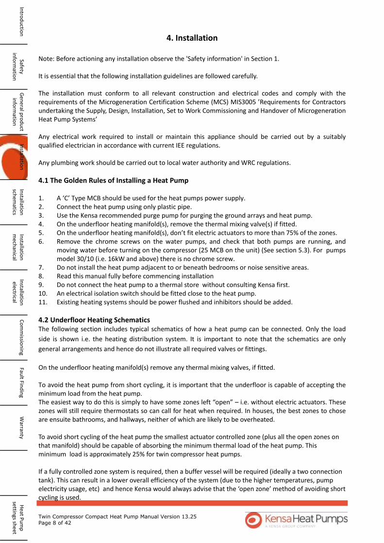
4.1 The Golden Rules of Installing a Heat Pump 1. A ‘C’ Type MCB should be used for the heat pumps power supply. 2. Connect the heat pump using only plastic pipe. 3. Use the Kensa recommended purge pump for purging the ground arrays and heat pump. 4. On the underfloor heating manifold(s), remove the thermal mixing valve(s) if fitted. 5. On the underfloor heating manifold(s), don’t fit electric actuators to more than 75% of the zones. 6. Remove the chrome screws on the water pumps, and check that both pumps are running, and
moving water before turning on the compressor (25 MCB on the unit) (See section 5.3). For pumps model 30/10 (i.e. 16kW and above) there is no chrome screw.
7. Do not install the heat pump adjacent to or beneath bedrooms or noise sensitive areas. 8. Read this manual fully before commencing installation 9. Do not connect the heat pump to a thermal store without consulting Kensa first. 10. An electrical isolation switch should be fitted close to the heat pump. 11. Existing heating systems should be power flushed and inhibitors should be added.
4.2 Underfloor Heating Schematics
The following section includes typical schematics of how a heat pump can be connected. Only the load
side is shown i.e. the heating distribution system. It is important to note that the schematics are only
general arrangements and hence do not illustrate all required valves or fittings.
On the underfloor heating manifold(s) remove any thermal mixing valves, if fitted. To avoid the heat pump from short cycling, it is important that the underfloor is capable of accepting the minimum load from the heat pump. The easiest way to do this is simply to have some zones left “open” – i.e. without electric actuators. These zones will still require thermostats so can call for heat when required. In houses, the best zones to chose are ensuite bathrooms, and hallways, neither of which are likely to be overheated. To avoid short cycling of the heat pump the smallest actuator controlled zone (plus all the open zones on that manifold) should be capable of absorbing the minimum thermal load of the heat pump. This minimum load is approximately 25% for twin compressor heat pumps. If a fully controlled zone system is required, then a buffer vessel will be required (ideally a two connection tank). This can result in a lower overall efficiency of the system (due to the higher temperatures, pump electricity usage, etc) and hence Kensa would always advise that the ‘open zone’ method of avoiding short cycling is used.
Safety in
form
ation
G
ene
ral pro
du
ct in
form
ation
In
stallation
In
stallation
sch
ematics
Installatio
n
mech
anical
Installatio
n
electrical C
om
missio
nin
g Fau
lt Find
ing
Warran
ty
Heat P
um
p
settings sh
eet
Intro
du
ction

Twin Compressor Compact Heat Pump Manual Version 13.25 Page 9 of 42
4.2.1 Underfloor with a single manifold. Space heating only
W
arra
nty
Fa
ult
Fin
din
g C
om
mis
sio
nin
g In
stal
lati
on
el
ectr
ical
In
stal
lati
on
m
ech
anic
al
Inst
alla
tio
n
sch
emat
ics
Inst
alla
tio
n
Gen
era
l pro
du
ct
info
rmat
ion
Sa
fety
info
rmat
ion
In
tro
du
ctio
n
Hea
t P
um
p
sett
ings
sh
eet
4.2.2 Underfloor with a multiple manifolds. Space heating only
Fig 2 Heat Pump with Underfloor and a Single Manifold Schematic
Kensa Supply
Kensa Supply
Fig 3 Heat Pump with Underfloor and a Multiple Manifolds Schematic

Twin Compressor Compact Heat Pump Manual Version 13.25 Page 10 of 42
4.3 Radiators. Space heating only
The following section includes typical schematics of how a heat pump can be connected. Only the load
side is shown i.e. the heating distribution system. It is important to note that the schematics are only
general arrangements and hence do not illustrate all required valves or fittings. They are only a guide and
should not be used as full installation plans.
When operated with radiators to avoid short circulating problems, one bypass radiator should be left
‘open’, i.e. any TRV is removed. This radiator can be positioned in areas such as halls or bathrooms.
Kensa would always recommend fitting an expansion vessel on the heating distribution circuit.
4.4 Domestic Hot Water (DHW) —Schematic
The DHW option needs to be specified at time of ordering. Warning - when a heat pump is used for heating domestic hot water, it may not get the water hot enough to kill the dangerous Legionella that can breed in hot water cylinders. Alternative arrangements should therefore be made to ensure the cylinder is pasteurised regularly. Under normal conditions the heat pump will provide heat for the space heating distribution system at its design temperature (typically 35oC for underfloor and 45-50oC for radiators). When the DHW time clock calls for production of DHW, the three-port valve diverts the flow from the heating distribution circuit into the indirect coil. The temperature of the water from the heat pump is raised to approximately 50oC. The light to the right of the controllers indicates when DHW production is operational. When the DHW production time period ends, the three port valve switches back to the underfloor distribution and the temperature drops back to its space heating design temperature. The heat pump then reverts to space heating mode or switches off if no zones are calling for heat. The heat pump will not re-enter into DHW mode until 2 hours has passed. Please contact Kensa if this time period needs to be adjusted . The maximum DHW temperature that the heat pump can achieve will be approximately 50-55oC. In summer, it could be higher, due to the warmer ground conditions. If 65oC is required all year round, it is recommended that an immersion heater is linked to a second channel on the DHW timeclock and this is programmed to operate for a period immediately following the DHW production. This means that the majority of the heating load for the DHW is produced at a lower cost using the heat pump, as opposed to using only the direct immersion heater. If 50oC water is acceptable, then it is recommended that the immersion heater is programmed to raise the temperature to 65oC once a week.
Fig 4 Heat Pump with Radiators Schematic
Kensa Supply
Safety in
form
ation
G
ene
ral pro
du
ct in
form
ation
In
stallation
In
stallation
sch
ematics
Installatio
n
mech
anical
Installatio
n
electrical C
om
missio
nin
g Fau
lt Find
ing
Warran
ty
Heat P
um
p
settings sh
eet
Intro
du
ction
Expansion vessel
Radiator with TRV
Bypass Radiator
Heat Pump
Radiator with TRV
Return
Flow

Twin Compressor Compact Heat Pump Manual Version 13.25 Page 11 of 42
4.4.1 Type of DHW Tank The larger size the coil within the tank, the better the heat transfer area and hence the better the DHW performance will be. (Refer to table 3.2). Ideally the coil should be a minimum of 0.2 sqm per kW DHW output from the heat pump. 4.4.2 DHW Tank Size The tank will need to be carefully sized to meet the DHW demand, based on the number of occupants and should have an acceptable recovery rate. Due to the lower DHW temperature achieved by the heat pump, a tank 30% larger than normal is recommended. This is due to the higher demand on the tank, as less cold water is used at the point of use to mix the lower temperature DHW to an acceptable temperature. 4.4.3 Immersion Heater Although not required by Building Regulations, it is generally advised that to provide legionella protection the tank is raised above 60oC at least once a week. To provide this we would recommend that a 3 kW electric immersion heater is fitted to the bottom of the tank, with its own dedicated 7- day timeclock. If DHW is required higher than 50oC then it is advisable that the immersion heater is programmed to operate for a period following the heat pump operation period to raise the temperature. This avoids the immersion heater taking all of the load. 4.4.4 Three Port Diverting Valve If the DHW option is ordered, a 3 port diverting valve (‘W’ plan) is provided by Kensa and is used to divert the flow when the timeclock calls for DHW production from space heating to the DHW tank. The valve’s electrical connections are connected to the heat pump’s internal wiring. Please note connection ‘A’ is DHW and ’B’ is space heating. Please note the valve should be installed with the motor at any angle vertical to 30° above the horizontal plane . 4.4.5 Tank Thermostat A tank thermostat is not required but maybe fitted and used as a tank safety stat if wired in series with the time clock. This should be set at not less than 65oC. 4.4.6 DHW timeclock A 24 hour time clock is required to control the production of DHW and is connected to the heat pump’s internal wiring. (See section 4.6.3). This timeclock is supplied by others. 4.4.7 Secondary Returns In long DHW pipe runs, to avoid excessive water draw off before the water is up to temperature at the
point of usage, it is common to install cylinders with a secondary return. This is not r e c o m m e n d e d for systems using heat pumps as it promotes mixing in the tank and a lower flow tem-perature off the cylinder. For long pipe runs, to avoid
W
arra
nty
Fa
ult
Fin
din
g C
om
mis
sio
nin
g In
stal
lati
on
el
ectr
ical
In
stal
lati
on
m
ech
anic
al
Inst
alla
tio
n
sch
emat
ics
Inst
alla
tio
n
Gen
era
l pro
du
ct
info
rmat
ion
Sa
fety
info
rmat
ion
In
tro
du
ctio
n
Hea
t P
um
p
sett
ings
sh
eet
DHW
out
Hot
water
cylinder
Flow boiler
Timed
water pump
Insulation
Return pipe
(smaller
diameter)
Timeclock
TimeClock
Point of usage
(taps)
Point of usage
(taps)
Automatic Air vent (installed at
the highest point)
Twin Compressor Compact Heat Pump Manual Version 13.25 Page 12 of 42
Cop
yrig
ht
Ken
sa E
ng
ineerin
g L
td 2
00
8
Heat
Pu
mp
, S
pace H
eati
ng
& D
HW
Sch
em
ati
c
AB
AB
See s
ep
arate
un
derfl
oo
r h
eati
ng
wir
ing
dia
gram
s f
or f
urth
er d
eta
iled
in
form
ati
on
Byela
w 1
4 K
it
Rem
oveab
le
Fil
lin
g L
oop
15
mm
cold
feed
in t
o t
op
up
gro
un
d a
rrays
Pow
er S
up
ply
.
Lo
cal
Isola
tor
Con
necte
d t
o "
D" o
r
"C
" t
yp
e M
CB
in
Dis
trib
uti
on
Bo
ard
(S
ee S
ecti
on
3.2
)
Un
derfl
oo
r/
DH
W
cir
cu
lati
on
wate
r p
um
p
an
d p
ressu
re g
au
ge
inte
gral
wit
h h
eat
pu
mp
Becau
se o
f
vib
rati
on
,
pip
es m
ust
be p
lasti
c
NO
T C
OP
PER
15
mm
cold
feed
in t
o t
op
up
grou
nd
arrays
Byela
w 1
4 k
it
Rem
ovab
le
Filli
ng
Lo
op
DH
W T
imeC
lock
Op
tio
nal
Exp
an
sio
n
Tan
k.
Not
op
tio
nal
for
Alu
pex u
nd
erfl
oor
pip
e
Ho
t w
ate
r o
ut
to f
au
cets
Im
mersio
n h
eate
r
con
troll
ed
by
ded
icate
d
7 d
ay t
ime c
lock
Cold
feed
in
3 P
ort
Div
erte
r V
alv
e
Ken
sa C
om
pact
Heat
Pu
mp
Sp
ace H
eati
ng
En
ab
le S
ign
al
Fro
m U
nd
erfl
oor
Heati
ng
Syste
m
Co
ntr
ol B
ox
Op
tio
nal D
HW
Tan
k O
ver T
em
p
Sta
t
DH
W T
an
k
Safety in
form
ation
G
ene
ral pro
du
ct in
form
ation
In
stallation
In
stallation
sch
ematics
Installatio
n
mech
anical
Installatio
n
electrical C
om
missio
nin
g Fau
lt Find
ing
Warran
ty
Heat P
um
p
settings sh
eet
Intro
du
ction
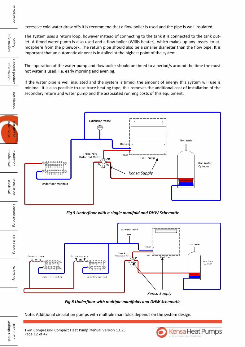
Fig 6 Underfloor with multiple manifolds and DHW Schematic
Kensa Supply
Kensa Supply
Fig 5 Underfloor with a single manifold and DHW Schematic
Note: Additional circulation pumps with multiple manifolds depends on the system design.
excessive cold water draw offs it is recommend that a flow boiler is used and the pipe is well insulated.
The operation of the water pump and flow boiler should be timed to a period/s around the time the most hot water is used, i.e. early morning and evening. If the water pipe is well insulated and the system is timed, the amount of energy this system will use is minimal. It is also possible to use trace heating tape, this removes the additional cost of installation of the secondary return and water pump and the associated running costs of this equipment.
The system uses a return loop, however instead of connecting to the tank it is connected to the tank out-let. A timed water pump is also used and a flow boiler (Willis heater), which makes up any losses to at-mosphere from the pipework. The return pipe should also be a smaller diameter than the flow pipe. It is important that an automatic air vent is installed at the highest point of the system.

Twin Compressor Compact Heat Pump Manual Version 13.25 Page 13 of 42
Cop
yrig
ht
Ken
sa E
ng
ineerin
g L
td 2
00
8
Heat
Pu
mp
, S
pace H
eati
ng
& D
HW
Sch
em
ati
c
AB
AB
See s
ep
arate
un
derfl
oo
r h
eati
ng
wir
ing
dia
gram
s f
or f
urth
er d
eta
iled
in
form
ati
on
Byela
w 1
4 K
it
Rem
oveab
le
Fil
lin
g L
oop
15
mm
cold
feed
in t
o t
op
up
gro
un
d a
rrays
Pow
er S
up
ply
.
Lo
cal
Isola
tor
Con
necte
d t
o "
D" o
r
"C
" t
yp
e M
CB
in
Dis
trib
uti
on
Bo
ard
(S
ee S
ecti
on
3.2
)
Un
derfl
oo
r/
DH
W
cir
cu
lati
on
wate
r p
um
p
an
d p
ressu
re g
au
ge
inte
gral
wit
h h
eat
pu
mp
Becau
se o
f
vib
rati
on
,
pip
es m
ust
be p
lasti
c
NO
T C
OP
PER
15
mm
cold
feed
in t
o t
op
up
grou
nd
arrays
Byela
w 1
4 k
it
Rem
ovab
le
Filli
ng
Lo
op
DH
W T
imeC
lock
Op
tio
nal
Exp
an
sio
n
Tan
k.
Not
op
tio
nal
for
Alu
pex u
nd
erfl
oor
pip
e
Ho
t w
ate
r o
ut
to f
au
cets
Im
mersio
n h
eate
r
con
troll
ed
by
ded
icate
d
7 d
ay t
ime c
lock
Cold
feed
in
3 P
ort
Div
erte
r V
alv
e
Ken
sa C
om
pact
Heat
Pu
mp
Sp
ace H
eati
ng
En
ab
le S
ign
al
Fro
m U
nd
erfl
oor
Heati
ng
Syste
m
Co
ntr
ol B
ox
Op
tio
nal D
HW
Tan
k O
ver T
em
p
Sta
t
DH
W T
an
k
Fig
7 H
eat
Pu
mp
wit
h D
HW
Sch
ema
tic
W
arra
nty
Fa
ult
Fin
din
g C
om
mis
sio
nin
g In
stal
lati
on
el
ectr
ical
In
stal
lati
on
m
ech
anic
al
Inst
alla
tio
n
sch
emat
ics
Inst
alla
tio
n
Gen
era
l pro
du
ct
info
rmat
ion
Sa
fety
info
rmat
ion
In
tro
du
ctio
n
Hea
t P
um
p
sett
ings
sh
eet
Ple
ase
no
te t
he
3 p
ort
div
erte
r va
lve
sho
uld
be
inst
alle
d w
ith
th
e m
oto
r at
an
y an
gle
vert
ical
to
30
° ab
ove
th
e h
ori
zon
tal p
lan
e .

Twin Compressor Compact Heat Pump Manual Version 13.25 Page 14 of 42
4.5 Mechanical Installation
4.5.1 Locating the Heat Pump
Decide on a suitable location for the Heat Pump. This should ideally be in the back of a domestic garage, or a utility room. It should not be placed in any inhabited space or near any noise sensitive areas. The Compact emits limited noise and vibration, and should not be placed adjacent to, or below bedrooms or occupied spaces. Take into account the “Recommended Clearances” when finalising the location. Check the appliance for transport damage. Under no circumstances should a damaged appliance be operated or installed. Position the appliance on a firm, level and substantial concrete base that will absorb vibration well away from any occupied rooms. Ensure that the appliance does not stand on the electrical supply cable. If the supply cable is damaged, it must be replaced. Ensure all pipes and wires are adequately supported where necessary, pipes are properly insulated and concentrations of inhibitor (where added) are correct. The appliance and any metal pipes should be properly earthed. A water treatment device should be provided in hard water areas. If the heat pump is being located in a damp environment, the ground array water pump should be insulated with a vapour barrier insulation such as Armaflex to avoid excessive condensation. Do not use the appliance as a shelf.
Approx. 900mm High
550mm 900mm
150mm required. Ideally 550mm for hood removal if required.
100mm
100mm 100mm
4.5.2 Recommend clearances
Fig 8 Heat Pump clearances
Safety in
form
ation
G
ene
ral pro
du
ct in
form
ation
In
stallation
In
stallation
sch
ematics
Installatio
n
mech
anical
Installatio
n
electrical C
om
missio
nin
g Fau
lt Find
ing
Warran
ty
Heat P
um
p
settings sh
eet
Intro
du
ction

Twin Compressor Compact Heat Pump Manual Version 13.25 Page 15 of 42
4.5.3 Installation of the heat pump
Ideally the heat pump should be placed next to an external wall allowing easy access to the externally mounted ground array manifold. Any pipes internal to the building must be insulated with vapour barrier insulation such as Armaflex. It is not recommended that the ground array manifold is installed within a building due to condensation and difficulty in lagging the manifold to overcome this. It is possible to place manifolds in underground chambers, however due to a possible flooding risk and easier access Kensa recommend that the manifold is placed on an external wall.
Fig 10 Manifold Slinky connections
Kensa Supply
W
arra
nty
Fa
ult
Fin
din
g C
om
mis
sio
nin
g In
stal
lati
on
el
ectr
ical
In
stal
lati
on
m
ech
anic
al
Inst
alla
tio
n
sch
emat
ics
Inst
alla
tio
n
Gen
era
l pro
du
ct
info
rmat
ion
Sa
fety
info
rmat
ion
In
tro
du
ctio
n
Hea
t P
um
p
sett
ings
sh
eet
Fig 9 Positioning of Heat Pump and Manifold
External Internal
An optional expansion vessel can be fitted to the slinky pipework.
Twin Compressor Compact Heat Pump Manual Version 13.25 Page 16 of 42
i. Unscrew the 4 x 5mm hex-socket screws, 2 on either side of the front panel. Remove the front panel.
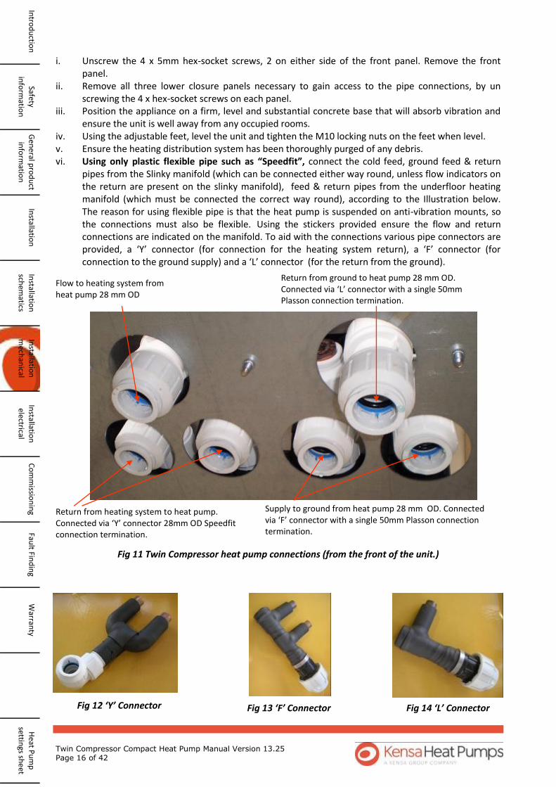
ii. Remove all three lower closure panels necessary to gain access to the pipe connections, by un screwing the 4 x hex-socket screws on each panel. iii. Position the appliance on a firm, level and substantial concrete base that will absorb vibration and ensure the unit is well away from any occupied rooms. iv. Using the adjustable feet, level the unit and tighten the M10 locking nuts on the feet when level. v. Ensure the heating distribution system has been thoroughly purged of any debris. vi. Using only plastic flexible pipe such as “Speedfit”, connect the cold feed, ground feed & return pipes from the Slinky manifold (which can be connected either way round, unless flow indicators on the return are present on the slinky manifold), feed & return pipes from the underfloor heating manifold (which must be connected the correct way round), according to the Illustration below. The reason for using flexible pipe is that the heat pump is suspended on anti-vibration mounts, so the connections must also be flexible. Using the stickers provided ensure the flow and return connections are indicated on the manifold. To aid with the connections various pipe connectors are provided, a ‘Y’ connector (for connection for the heating system return), a ‘F’ connector (for connection to the ground supply) and a ‘L’ connector (for the return from the ground).
Flow to heating system from heat pump 28 mm OD
Return from heating system to heat pump. Connected via ‘Y’ connector 28mm OD Speedfit connection termination.
Supply to ground from heat pump 28 mm OD. Connected via ‘F’ connector with a single 50mm Plasson connection termination.
Return from ground to heat pump 28 mm OD. Connected via ‘L’ connector with a single 50mm Plasson connection termination.
Fig 11 Twin Compressor heat pump connections (from the front of the unit.)
Fig 12 ‘Y’ Connector Fig 13 ‘F’ Connector Fig 14 ‘L’ Connector
Safety in
form
ation
G
ene
ral pro
du
ct in
form
ation
In
stallation
In
stallation
sch
ematics
Installatio
n
mech
anical
Installatio
n
electrical C
om
missio
nin
g Fau
lt Find
ing
Warran
ty
Heat P
um
p
settings sh
eet
Intro
du
ction

Twin Compressor Compact Heat Pump Manual Version 13.25 Page 17 of 42
vii. Thread the power supply and timeclock/room thermostat wires from under the Compact into the control box and connect them to the terminals required, ( see electrical installation section ). viii. If required fit the optional weather compensation sensor to a North facing wall, and connect with two-core minimum 0.5mm sq cable (see Section 4.6.4). The use of weather compensation on heat pumps is unlikely to give any significant cost savings and can actually increase the cost of running a heat pump. For this reason, Kensa Heat Pumps are supplied with this function disabled in the software. ix. For applications where Domestic Hot Water has been specified a 3 port diverting valve (‘W’ plan) is provided by Kensa and when the timeclock calls for DHW production is used to divert the flow from space heating to an indirect coil in the DHW tank, (See DHW schematic, Section 4.4). The diverting valve should be first connection in the heat pumps flow line, before any underfloor heating manifolds. The valve’s electrical connections are connected to the heat pump’s internal wiring. (See 4.6.3) x. Check and rectify any leaks that may be in the plumbing system. xi. The appliance should be left for 12 hours after installation before it is turned on, to allow the refrigerant to settle. The area where the heat pump is installed must be dry and rodent free.
The government is introducing the Renewable Heat Incentive (RHI) to support renewable heat generation in the domestic sector. The scheme will offer tariff payments for supported technologies which include MCS (or equivalent)-certified solar thermal systems, ground source heat pumps, air source heat pumps and biomass boilers or stoves with back boilers for use in the domestic sector.
All RHI installations should be made meter-ready. In addition, in some cases, applicants will require metering for payment in order for their systems to be RHI-compliant, whilst in other cases, applicants could be paid extra for monitoring of system performance.
MCS guidelines make three distinct types of meter installation
Meter-ready- All RHI installations should be meter-ready for DECC’s own metering to be fitted to the site if selected. Metering for payment- Where a heat pump or biomass boiler is installed alongside certain other heating systems or where the installer is advised that the property is a second home, then the renewable heating system shall be metered in order to receive payment under the RHI. Metering and Monitoring Service Packages- A Customer may install an optional metering and monitoring service package for either a pellet biomass boiler or a heat pump for which they will receive a financial uplift. The specifications for installation of meters as part of these packages are detailed in this section along with any other requirements in order for the package to be installed in a form that is compliant with the RHI.
For information on Metering for payment and Metering and Monitoring Service Packages it is recommended that the MCS document MCS Domestic RHI Metering Guidance V1.0 is consulted. The section below covers ‘meter ready’ installations only. 4.5.4.1 Meter Ready Installations Some installations incentivised through the RHI will have DECC’s own metering fitted where the metering data may then be used to allow DECC to evaluate the effectiveness of the policy and data may be shared
W
arra
nty
Fa
ult
Fin
din
g C
om
mis
sio
nin
g In
stal
lati
on
el
ectr
ical
In
stal
lati
on
m
ech
anic
al
Inst
alla
tio
n
sch
emat
ics
Inst
alla
tio
n
Gen
era
l pro
du
ct
info
rmat
ion
Sa
fety
info
rmat
ion
In
tro
du
ctio
n
Hea
t P
um
p
sett
ings
sh
eet
4.5.4 Meter Installations
Twin Compressor Compact Heat Pump Manual Version 13.25 Page 18 of 42
Safety in
form
ation
G
ene
ral pro
du
ct in
form
ation
In
stallation
In
stallation
sch
ematics
Installatio
n
mech
anical
Installatio
n
electrical C
om
missio
nin
g Fau
lt Find
ing
Warran
ty
Heat P
um
p
settings sh
eet
Intro
du
ction
with MCS.
DECC intends to install meters to monitor the heat output from a renewable heating system, the energy consumed by those same heat sources, and the heat output from any back-up fossil fuel systems. This could require engineers, appointed by DECC, to install a number of heat meters, electricity meters or other energy meters, depending on the specific heating system and manner of installation. In addition, DECC will install a number of temperature sensors to develop an understanding of the behaviour of a range of heating systems, for example temperature measurement of space heating flow and domestic hot water flow. The sensor outputs will be connected to a logger that will store all readings and regularly transmit them to a centralized secure data source.
All RHI-compliant renewable heating installations should be made meter-ready. MCS installers should:
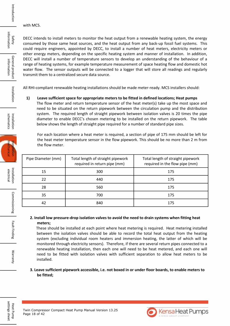
1) Leave sufficient space for appropriate meters to be fitted in defined locations; Heat pumps The flow meter and return temperature sensor of the heat meter(s) take up the most space and need to be situated on the return pipework between the circulation pump and the distribution system. The required length of straight pipework between isolation valves is 20 times the pipe diameter to enable DECC’s chosen metering to be installed on the return pipework. The table below shows the length of straight pipe required for a number of standard pipe sizes.
For each location where a heat meter is required, a section of pipe of 175 mm should be left for the heat meter temperature sensor in the flow pipework. This should be no more than 2 m from the flow meter.
2. Install low pressure-drop isolation valves to avoid the need to drain systems when fitting heat
meters; These should be installed at each point where heat metering is required. Heat metering installed between the isolation valves should be able to record the total heat output from the heating system (excluding individual room heaters and immersion heating, the latter of which will be monitored through electricity sensors). Therefore, if there are several return pipes connected to a renewable heating installation, then each one will need to be heat metered, and each one will need to be fitted with isolation valves with sufficient separation to allow heat meters to be installed.
3. Leave sufficient pipework accessible, i.e. not boxed in or under floor boards, to enable meters to be fitted;
Pipe Diameter (mm) Total length of straight pipework required in return pipe (mm)
Total length of straight pipework required in the flow pipe (mm)
15 300 175
22 440 175
28 560 175
35 700 175
42 840 175
Twin Compressor Compact Heat Pump Manual Version 13.25 Page 19 of 42
W
arra
nty
Fa
ult
Fin
din
g C
om
mis
sio
nin
g In
stal
lati
on
el
ectr
ical
In
stal
lati
on
m
ech
anic
al
Inst
alla
tio
n
sch
emat
ics
Inst
alla
tio
n
Gen
era
l pro
du
ct
info
rmat
ion
Sa
fety
info
rmat
ion
In
tro
du
ctio
n
Hea
t P
um
p
sett
ings
sh
eet
Feedback information about the installation DECC will need to know a number of factors about a site so an application will not be considered to be
“meter-ready” if such information has not been provided. The information shall include the following:
To be fed back to MCS through the Compliance Certificates: Whether it has been possible to make a system meter-ready in accordance with the above
requirements and, if not, the reason why; To be reported to the Customer as part of the document pack (so that the Customer can respond to
DECC questions at a later date): Whether the thermal transfer fluid in any metering location is composed of water or a water/
inhibiter/antifreeze mixture and what are the components of the mixture concerned; Whether the heat pump provides hot water and whether this is also heated with an immersion
heater, solar thermal or other system;
Whether the heat pump has a single-phase or three-phase connection.
Notes on making an installation ‘meter ready’
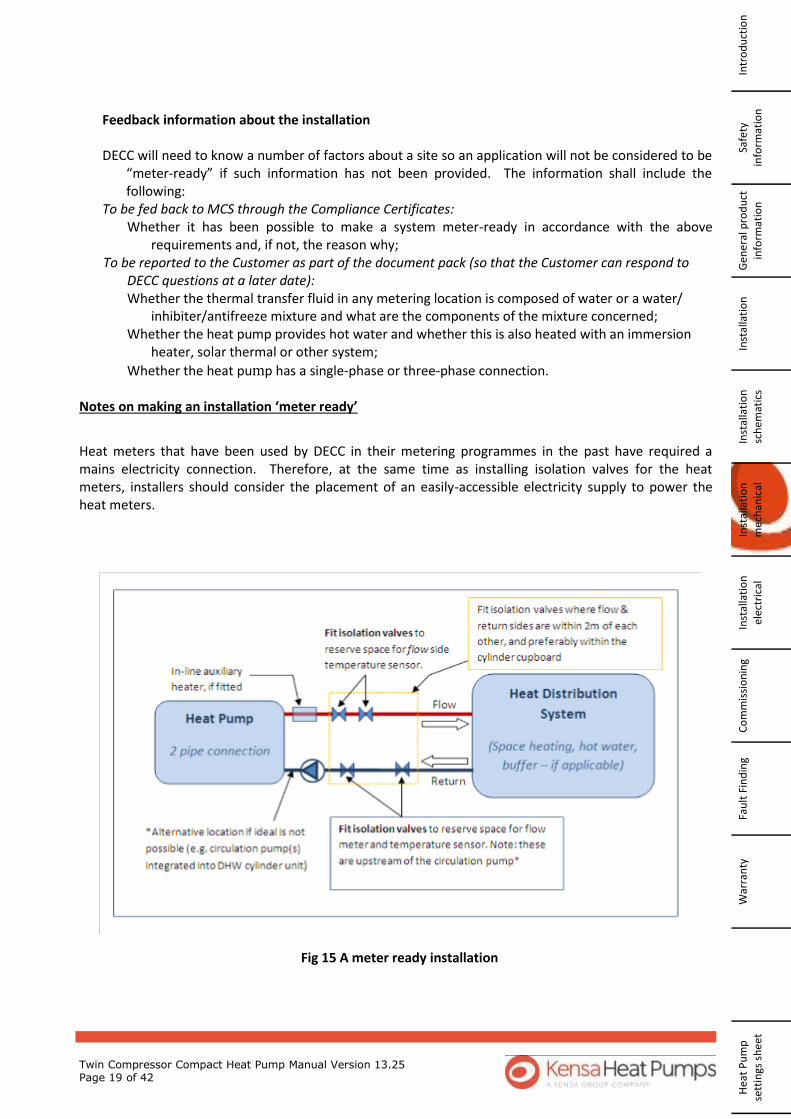
Heat meters that have been used by DECC in their metering programmes in the past have required a mains electricity connection. Therefore, at the same time as installing isolation valves for the heat meters, installers should consider the placement of an easily-accessible electricity supply to power the heat meters.
Fig 15 A meter ready installation

Twin Compressor Compact Heat Pump Manual Version 13.25 Page 20 of 42
4.6 Electrical Installation
The Kensa Compact heat pump range is available in either single or three phase power supply versions. Any electrical work required to install or maintain this appliance should be carried out by a suitably qualified electrician in accordance with current IEE regulations
To access the wiring terminals :- i. remove the heat pump front cover by unscrewing the 2 x 5mm hex socket screws on each side of
the heat pump. ii. remove the electronics cover plate by unscrewing the two 3mm cross head screws on the front
lower cover plate.
2 x 3mm cross head
Cables should enter the unit from below using the cable entry ports provided. The following sections detail the wiring connections for various applications. In all wiring diagrams the terminals marked ‘Reverse Cycle’ change the mode from heating to cooling (If
Fig 17 Electrics box with the lower front cover removed
Wiring Terminals
Controller
Fig 16 Position of Hex screws on the Electronics cover Plate
Safety in
form
ation
G
ene
ral pro
du
ct in
form
ation
In
stallation
In
stallation
sch
ematics
Installatio
n
mech
anical
Installatio
n
electrical C
om
missio
nin
g Fau
lt Find
ing
Warran
ty
Heat P
um
p
settings sh
eet
Intro
du
ction
MCBs

Twin Compressor Compact Heat Pump Manual Version 13.25 Page 21 of 42
4.6.1 Single Phase
4.6.1.1 Single Underfloor Control Unit
this option is fitted). This requires a volt free relay, open is heating mode, closed cooling. The terminals marked ‘Fault’ are to provide remote indication that a fault has occurred within the heat pump. This is a volt free relay and the internal relay will close if a fault occurs. All installations should be fitted with a local isolation switch immediately adjacent to the heat pump. Wiring for the connection between the heat pump and local isolator will be a maximum of 10mm2. Wiring sizes between the consumer unit (fuse box) and local isolator will depend on the length of cable run and how the cable is installed. As this is site dependant, the site electrician should and is responsible for calculating this.
Fig 18 Heat pump wiring—Single Underfloor Manifold
W
arra
nty
Fa
ult
Fin
din
g C
om
mis
sio
nin
g In
stal
lati
on
el
ectr
ical
In
stal
lati
on
m
ech
anic
al
Inst
alla
tio
n
sch
emat
ics
Inst
alla
tio
n
Gen
era
l pro
du
ct
info
rmat
ion
Sa
fety
info
rmat
ion
In
tro
du
ctio
n
Hea
t P
um
p
sett
ings
sh
eet
Underfloor Electric Actuator
Output Refer to
Manufacturers Literature
230 Vac 50Hz power supply via a Type C MCB in the buildings
distribution Board
Timeclock input. Refer to Manufacturers Literature
Thermostat inputs. Refer to Manufacturers Literature
Boiler Relay
DHW time clock
DHW Valve
Fault Reverse
Cycle
Heat Pump Wiring Terminal block
Control Unit Power Supply
Enable Signal connection is supplied with a temporary link across it . This should be removed after commissioning and connection to the heating control system.
(Terminals 1 and 2)
Heat Pump Enable Signal No Call 0-50V Call >120V 50V < Call voltages < 120V are not permitted

Twin Compressor Compact Heat Pump Manual Version 13.25 Page 22 of 42
230 Vac 50Hz power supply via a Type C MCB in the
buildings distribution Board
Thermostat inputs. Refer to Manufacturers Literature
Underfloor Electric Actuator
Output Refer to
Manufacturers Literature
Boiler Relay
DHW time clock
Heat Pump Wiring Terminal block
DHW valve
Reverse cycle
Underfloor Electric Actuator
Output Refer to
Manufacturers Literature
Thermostat inputs. Refer to Manufacturers Literature
Boiler Relay
Fault
230 Vac 50Hz power supply via a Type C MCB in the
buildings distribution Board
DHW time clock
DHW valve
Fault Reverse cycle
Heat Pump Wiring Terminal block
4.6.1.2 Multiple Underfloor Control Units
4.6.1.3 Radiator with Thermostat
Fig 19 Heat Pump W i r i n g — M u l t i p l e Underfloor Control Units
Safety in
form
ation
G
ene
ral pro
du
ct in
form
ation
In
stallation
In
stallation
sch
ematics
Installatio
n
mech
anical
Installatio
n
electrical C
om
missio
nin
g Fau
lt Find
ing
Warran
ty
Heat P
um
p
settings sh
eet
Intro
du
ction
Fig 20 Heat Pump Wiring—Radiators with Thermostat
Enable Signal link removed
Enable Signal link removed
Heat Pump Enable Signal No Call 0-50V Call >120V 50V < Call voltages < 120V are not permitted
Heat Pump Enable Signal No Call 0-50V Call >120V 50V < Call voltages < 120V are not permitted

Twin Compressor Compact Heat Pump Manual Version 13.25 Page 23 of 42
400 Vac 50Hz Power Supply
DHW time clock
DHW valve
Fault Reverse cycle
Heat Pump Wiring Terminal block
Enable Signal
4.6.2 Three Phase Power Supplies
4.6.3 DHW time clock and 3 way diverting valve wiring
Note: The hot water cylinder high limit stat maybe required to be wired into the live return from the DHW Heating Time Clock. Note: If DHW option is enabled after commissioning and connection to DHW time clock, remove DHW enable link.
Fig 21 Heat pump Wiring—Three Phase Power Supplies
Fig 22 Heat Pump Wiring—DHW
W
arra
nty
Fa
ult
Fin
din
g C
om
mis
sio
nin
g In
stal
lati
on
el
ectr
ical
In
stal
lati
on
m
ech
anic
al
Inst
alla
tio
n
sch
emat
ics
Inst
alla
tio
n
Gen
era
l pro
du
ct
info
rmat
ion
Sa
fety
info
rmat
ion
In
tro
du
ctio
n
Hea
t P
um
p
sett
ings
sh
eet
230 Vac 50Hz power supply via a Type C MCB in the
buildings distribution Board
To/From Heating Control System i.e. Underfloor Control
Unit
Heat Pump Wiring Terminal block
Fault Reverse cycle
Optional High Limit DHW Stat
Enable Signal links removed
Heat Pump Enable Signal No Call 0-50V Call >120V 50V < Call voltages < 120V are not permitted
Heat Pump Enable Signal No Call 0-50V Call >120V 50V < Call voltages < 120V are not permitted
Twin Compressor Compact Heat Pump Manual Version 13.25 Page 24 of 42
4.6.4 Weather Compensation (Optional)
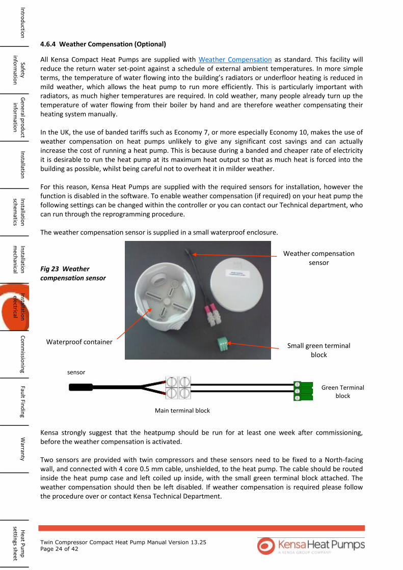
All Kensa Compact Heat Pumps are supplied with Weather Compensation as standard. This facility will reduce the return water set-point against a schedule of external ambient temperatures. In more simple terms, the temperature of water flowing into the building’s radiators or underfloor heating is reduced in mild weather, which allows the heat pump to run more efficiently. This is particularly important with radiators, as much higher temperatures are required. In cold weather, many people already turn up the temperature of water flowing from their boiler by hand and are therefore weather compensating their heating system manually. In the UK, the use of banded tariffs such as Economy 7, or more especially Economy 10, makes the use of weather compensation on heat pumps unlikely to give any significant cost savings and can actually increase the cost of running a heat pump. This is because during a banded and cheaper rate of electricity it is desirable to run the heat pump at its maximum heat output so that as much heat is forced into the building as possible, whilst being careful not to overheat it in milder weather. For this reason, Kensa Heat Pumps are supplied with the required sensors for installation, however the function is disabled in the software. To enable weather compensation (if required) on your heat pump the following settings can be changed within the controller or you can contact our Technical department, who can run through the reprogramming procedure. The weather compensation sensor is supplied in a small waterproof enclosure.
Kensa strongly suggest that the heatpump should be run for at least one week after commissioning, before the weather compensation is activated. Two sensors are provided with twin compressors and these sensors need to be fixed to a North-facing wall, and connected with 4 core 0.5 mm cable, unshielded, to the heat pump. The cable should be routed inside the heat pump case and left coiled up inside, with the small green terminal block attached. The weather compensation should then be left disabled. If weather compensation is required please follow the procedure over or contact Kensa Technical Department.
Small green terminal block
Weather compensation sensor
Waterproof container
sensor
Green Terminal block
Main terminal block
Fig 23 Weather compensation sensor
Safety in
form
ation
G
ene
ral pro
du
ct in
form
ation
In
stallation
In
stallation
sch
ematics
Installatio
n
mech
anical
Installatio
n
electrical C
om
missio
nin
g Fau
lt Find
ing
Warran
ty
Heat P
um
p
settings sh
eet
Intro
du
ction
Twin Compressor Compact Heat Pump Manual Version 13.25 Page 25 of 42
W
arra
nty
Fa
ult
Fin
din
g C
om
mis
sio
nin
g In
stal
lati
on
el
ectr
ical
In
stal
lati
on
m
ech
anic
al
Inst
alla
tio
n
sch
emat
ics
Inst
alla
tio
n
Gen
era
l pro
du
ct
info
rmat
ion
Sa
fety
info
rmat
ion
In
tro
du
ctio
n
Hea
t P
um
p
sett
ings
sh
eet
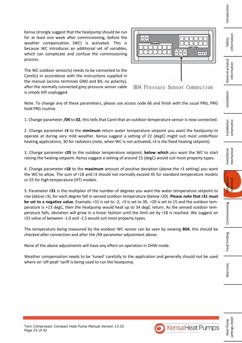
Kensa strongly suggest that the heatpump should be run for at least one week after commissioning, before the weather compensation (WC) is activated. This is because WC introduces an additional set of variables, which can complicate and confuse the commissioning process. The WC outdoor sensor(s) needs to be connected to the Carel(s) in accordance with the instructions supplied in the manual (across terminals GND and B4, no polarity), after the normally connected grey pressure sensor cable is simply left unplugged. Note. To change any of these parameters, please use access code 66 and finish with the usual PRG, PRG hold PRG routine. 1. Change parameter /04 to 02, this tells that Carel that an outdoor temperature sensor is now connected. 2. Change parameter r3 to the minimum return water temperature setpoint you want the heatpump to operate at during very mild weather. Kensa suggest a setting of 22 (degC) might suit most underfloor heating applications, 30 for radiators (note, when WC is not activated, r3 is the fixed heating setpoint). 3. Change parameter r20 to the outdoor temperature setpoint, below which you want the WC to start raising the heating setpoint. Kensa suggest a setting of around 15 (degC) would suit most property types. 4. Change parameter r18 to the maximum amount of positive deviation (above the r3 setting) you want the WC to allow. The sum of r18 and r3 should not normally exceed 45 for standard temperature models or 55 for high temperature (HT) models. 5. Parameter r31 is the multiplier of the number of degrees you want the water temperature setpoint to rise (above r3), for each degree fall in sensed outdoor temperature (below r20). Please note that r31 must be set to a negative value. Example: r31 is set to -2, r3 is set to 30, r20 is set to 15 and the outdoor tem-perature is +13 degC, then the heatpump would heat up to 34 degC return. As the sensed outdoor tem-perature falls, deviation will grow in a linear fashion until the limit set by r18 is reached. We suggest an r31 value of between -1.0 and -1.5 would suit most property types. The temperature being measured by the outdoor WC sensor can be seen by viewing B04, this should be checked after connection and after the /04 parameter adjustment above. None of the above adjustments will have any effect on operation in DHW mode. Weather compensation needs to be ‘tuned’ carefully to the application and generally should not be used where an ‘off peak’ tariff is being used to run the heatpump.

Twin Compressor Compact Heat Pump Manual Version 13.25 Page 26 of 42
Safety in
form
ation
G
ene
ral pro
du
ct in
form
ation
In
stallation
In
stallation
sch
ematics
Installatio
n
mech
anical
Installatio
n
electrical C
om
missio
nin
g Fau
lt Find
ing
Warran
ty
Heat P
um
p
settings sh
eet
Intro
du
ction
To enable weather compensation
Steps Action Display
1 Unplug pressure transducer from the internal Carel controller
2 Plug weather compensation plug into internal Carel controller
3 Press and hold SET (or PRG & SEL together on the internal controller)
and release when 0 is displayed 0
4 Press and hold the up button, and release when 66 is displayed 66
5 Press SEL "S-P"
6 Press SEL "-/-"
7 Press SEL "-/01-"
8 Press the up arrow until -/04 "-/04-"
9 Press SEL Default 03
10 Change to 02 02
11 Press SEL "-/04-"
12 Press PRG "-/-"
13 Press the up arrow until -r- is displayed "-r-"
14 Press SEL "r01"
15 Press up arrow until r03 is displayed "r03"
16 Press SEL Default 26
17 Set to 22 for under floor, 30 for radiators
18 Press SEL "r03"
19 Press the up arrow until r20 is displayed "r20"
20 Press SEL Default 0.0
21 Set to 15 15
22 Press SEL "r20"
23 Press the down arrow until r18 is displayed "r18"
24 Press SEL Default 0.3
25 Set to, 18 for under floor, 15 for radiators, (20 for Radiators High tem-
perature models)
26 Press SEL "r18"
27 Press the up arrow until r31 is displayed "r31"
28 Press SEL Default 0.0
29 Set to (minus) -1.2 "-1.2"
30 Press SEL r31
31 Press PRG twice until S-P is displayed S-P
32 Press and hold PRG until the display returns to normal
The weather compensation settings will need to be adjusted over
the course of at least one winter

Twin Compressor Compact Heat Pump Manual Version 13.25 Page 27 of 42
i. Remove the plastic blanking plugs, and connect the purge pump to the fill and purge ports on the Slinky manifold, see diagram over leaf. Keep the isolating valve to the heat pump closed. The purge ports can be connected either way round.
ii. Connect the purge pump to draw from an 80 litre dustbin half filled with clean water. This pump must be capable of circulating 60 litres per minute against a pressure of 1 bar. If the pump’s electrical rating is less than 1 kW, then it is unlikely to be suitable. Kensa only recommend the use of the Clarke SPE1200SS pump as above. The water level in the dustbin will need to be topped up constantly during the following process. The pump may need priming by pouring water into its priming port until it overflows.
5. Commissioning
After all mechanical and electrical work has been completed, the following commissioning instructions should be followed.
5.1 Purging the ground array of air.
It is important for correct operation that all the air is removed from the ground arrays. Slinkies consist of a large number of 1 metre diameter loops of 32mm OD pipe and air can collect at the top of these loops. Even vertical (ie. drilled) arrays can have trapped air and should be purged. To remove the air from ground arrays, a suitable pump will be required. For slinkies, the longest slinky trench is 50 metres, which will contain a total of approx. 300 metres of pipe. To achieve the minimum velocity required to remove the air, a minimum pump power in excess of 1 kW is required. In addition, the pump needs to have a flow of at least 60 litres per minute against a pressure of at least 1 bar. To achieve this, a multi-stage pump is required. A normal rising cold water main in a building has insufficient flow to force out this air. Mains water is also “aerated”, so should not be used. The recommended purge pump is the Clarke SPE1200SS (part no. 051012200). The pump is supplied ready to take a 1” BSP fitting. Two x 1” BSP male to 28 mm compression fittings are required to enable the pump to be connected to the slinky manifold using 28 mm “Speedfit” or similar pipe and elbows. These are readily available from plumbing merchants. The Clarke SPE1200SS can achieve as much as 5 bar pressure against a closed valve, so ensure the connections to the pump and manifold are robust.
5.1.1 Purging Procedure for Multiple slinkies.
Fig 24 Clarke SPE1200SS Purge Pump
W
arra
nty
Fa
ult
Fin
din
g C
om
mis
sio
nin
g In
stal
lati
on
el
ectr
ical
In
stal
lati
on
m
ech
anic
al
Inst
alla
tio
n
sch
emat
ics
Inst
alla
tio
n
Gen
era
l pro
du
ct
info
rmat
ion
Sa
fety
info
rmat
ion
In
tro
du
ctio
n
Hea
t P
um
p
sett
ings
sh
eet

Twin Compressor Compact Heat Pump Manual Version 13.25 Page 28 of 42
Kensa Supply
iii. Place a filter such as a kitchen sieve over the pipe returning water to the dustbin so any debris will be captured. Ensure all valves are closed including the heat pump valve V1. Open the valves on the manifold in the following order (refer to above diagram Fig 26) :-
a. Open Areturn b. Open Aflow c. Open both purge valves
Start the purge pump, being careful that the water pipe returning water to the dustbin is secure. iv. If the water level in the dustbin does not start to drop, then repeat the pump priming. No water
V1
flow return Fig 26 Slinky manifold connections
Safety in
form
ation
G
ene
ral pro
du
ct in
form
ation
In
stallation
In
stallation
sch
ematics
Installatio
n
mech
anical
Installatio
n
electrical C
om
missio
nin
g Fau
lt Find
ing
Warran
ty
Heat P
um
p
settings sh
eet
Intro
du
ction
Fig 25 Slinky purging kit connected to a manifold
Clarke Purge Pump
Pump priming port
80 litre dustbin
An optional expansion vessel can be fitted to the slinky pipework.
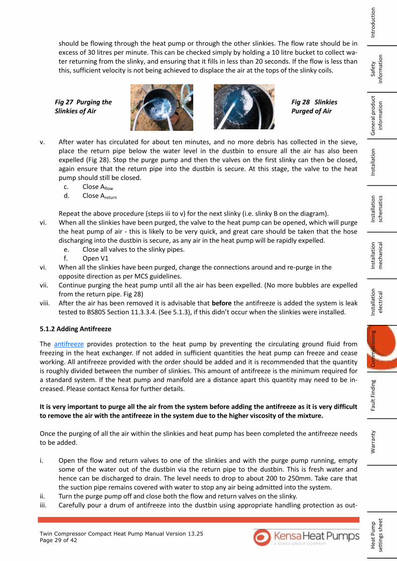
Twin Compressor Compact Heat Pump Manual Version 13.25 Page 29 of 42
should be flowing through the heat pump or through the other slinkies. The flow rate should be in excess of 30 litres per minute. This can be checked simply by holding a 10 litre bucket to collect wa-ter returning from the slinky, and ensuring that it fills in less than 20 seconds. If the flow is less than this, sufficient velocity is not being achieved to displace the air at the tops of the slinky coils.
v. After water has circulated for about ten minutes, and no more debris has collected in the sieve,
place the return pipe below the water level in the dustbin to ensure all the air has also been expelled (Fig 28). Stop the purge pump and then the valves on the first slinky can then be closed, again ensure that the return pipe into the dustbin is secure. At this stage, the valve to the heat pump should still be closed.
c. Close Aflow d. Close Areturn
Repeat the above procedure (steps iii to v) for the next slinky (i.e. slinky B on the diagram). vi. When all the slinkies have been purged, the valve to the heat pump can be opened, which will purge
the heat pump of air - this is likely to be very quick, and great care should be taken that the hose discharging into the dustbin is secure, as any air in the heat pump will be rapidly expelled.
e. Close all valves to the slinky pipes. f. Open V1
vi. When all the slinkies have been purged, change the connections around and re-purge in the opposite direction as per MCS guidelines.
vii. Continue purging the heat pump until all the air has been expelled. (No more bubbles are expelled from the return pipe. Fig 28)
viii. After the air has been removed it is advisable that before the antifreeze is added the system is leak tested to BS805 Section 11.3.3.4. (See 5.1.3), if this didn’t occur when the slinkies were installed.
Fig 27 Purging the Slinkies of Air
Fig 28 Slinkies Purged of Air
5.1.2 Adding Antifreeze
The antifreeze provides protection to the heat pump by preventing the circulating ground fluid from freezing in the heat exchanger. If not added in sufficient quantities the heat pump can freeze and cease working. All antifreeze provided with the order should be added and it is recommended that the quantity is roughly divided between the number of slinkies. This amount of antifreeze is the minimum required for a standard system. If the heat pump and manifold are a distance apart this quantity may need to be in-creased. Please contact Kensa for further details. It is very important to purge all the air from the system before adding the antifreeze as it is very difficult to remove the air with the antifreeze in the system due to the higher viscosity of the mixture. Once the purging of all the air within the slinkies and heat pump has been completed the antifreeze needs to be added. i. Open the flow and return valves to one of the slinkies and with the purge pump running, empty
some of the water out of the dustbin via the return pipe to the dustbin. This is fresh water and hence can be discharged to drain. The level needs to drop to about 200 to 250mm. Take care that the suction pipe remains covered with water to stop any air being admitted into the system.
ii. Turn the purge pump off and close both the flow and return valves on the slinky. iii. Carefully pour a drum of antifreeze into the dustbin using appropriate handling protection as out-
W
arra
nty
Fa
ult
Fin
din
g C
om
mis
sio
nin
g In
stal
lati
on
el
ectr
ical
In
stal
lati
on
m
ech
anic
al
Inst
alla
tio
n
sch
emat
ics
Inst
alla
tio
n
Gen
era
l pro
du
ct
info
rmat
ion
Sa
fety
info
rmat
ion
In
tro
du
ctio
n
Hea
t P
um
p
sett
ings
sh
eet

Twin Compressor Compact Heat Pump Manual Version 13.25 Page 30 of 42
lined in the COSH. Allow the solution to settle for a few moments to allow any trapped air to escape. iv. Open the valve V1 to the heat pump and start the purge pump to circulate the antifreeze around the
system. Leave the pump running until antifreeze is seen returning to the dustbin. The amount of time this will take depends upon the length of the header pipe.
v. Close the valve to the heat pump and turn the purge pump off. vi. Open the first slinky flow and return valve and with the return pipe inside of the dustbin start the
purge pump. Once the return discharge runs clear, i.e. It’s discharging fresh water, move the return pipe out of the dustbin and discharge this fresh water to drain until the antifreeze level within the dustbin drops to approximately 200-250mm. Take care that the suction pipe remains covered with water to stop any air being admitted into the system. (Depending on the length of header pipe addi-tional antifreeze might be required to be added at this stage). The discharge pipe can then be placed back into the dustbin and the purge pump should be run for about 5-10mins and then turned off.
vii. Close the slinky valves; add the next quantity of antifreeze to the dustbin and repeat the above steps vi and vii for each individual slinky.
i. Open all valves EXCEPT THE DISCHARGE PURGE CONNECTION. Keep a close eye on the level of water
in the dustbin and start the purge pump. This should pressurise the whole system. If the level of water drops significantly this indicates the system hasn’t been correctly purged of air and needs to be re-purged.
ii. Close the fill purge valve on the slinky manifold with the pump running, so that the ground array is left under pressure.
iii. Most purge pumps will attain around 5 bar, and the circuit should be left at this pressure for a minimum of 15 mins, as any leaks will become immediately apparent. The pressure will slowly fall as the pipes in the ground arrays slowly expand in the coming months, and may need topping up using the cold fill system provided.
iv. Remove the purging equipment. Replace the plastic blanking plugs in the slinky manifold purge connections.
There should be approximately 200-250mm of water/antifreeze mix within the dustbin which can be poured back into an empty drum and disposed off according to the disposal instructions in section 8 or retained for topping up the system. To mix the antifreeze around the ground arrays thoroughly, it is advised that the ground array circulation pump is turned on via the 6 amp MCB on the heat pump. (Note DO NOT TURN THE COMPRESSOR 25 amp MCB ON). This ground array circulation pump should be left running for two to three hours to ensure the antifreeze is mixed in all the slinkies and the heat pump. (Note: - the floor pump will also run.)
Safety in
form
ation
G
ene
ral pro
du
ct in
form
ation
In
stallation
In
stallation
sch
ematics
Installatio
n
mech
anical
Installatio
n
electrical C
om
missio
nin
g Fau
lt Find
ing
Warran
ty
Heat P
um
p
settings sh
eet
Intro
du
ction
5.1.3 Pressurising the system.
5.1.3.1 Pressure Testing in accordance to BS805 Section 11.3.3.4
In accordance with MCS Guidelines, leak tightness (pressure) testing has to follow the EN 805 prescriptions in section 11.3.3.4. This test should be carried out after the ground arrays have been purged but before the antifreeze is added. For polyethylene (PE) tubes, the pressure testing has to be carried out as a ‘compression test’. An overpressure (inside-outside) is applied to the pipe over the whole length. This step inflates slightly the PE pipe over its whole length. Then a sudden pressure drop of around 10% of the testing pressure is applied. This pressure drop allows the pipe to compress again. If the pipe is tight, a pressure increase is measured. This test should only be carried out on the ground arrays with the heat pump isolated from the test. To perform such a test, the following equipment is needed: A high-pressure pump or a manually operated pump 2 stop valves

Twin Compressor Compact Heat Pump Manual Version 13.25 Page 31 of 42
Fig 29 Leak Tightness Configuration
1 manometer 0 -16 bar A de-aeration device (if any point of the ground array is at a high point where air can collect) Test procedure in detail (Fig. 30):
1 h Idle period. No overpressure is applied to the tube .
Apply the test pressure. For PE100/PN16/SDR11 ground arrays this should be > 7.5 barg. If the heat pump is within the pressure test this should be less than 10 barg. For other materials follow the
manufacturer's specification
10 min Keep up pressure test
1 h Idle period. The tube is going to expand over the whole length
Pressure measurement. The pressure drop may not exceed the manufacturer‟s specifications
Sudden pressure drop of at least 10% of the test pressure
10 mins. First pressure measurement A
20 mins. Second pressure measurement B
30 mins. Third and final pressure measurement C
W
arra
nty
Fa
ult
Fin
din
g C
om
mis
sio
nin
g In
stal
lati
on
el
ectr
ical
In
stal
lati
on
m
ech
anic
al
Inst
alla
tio
n
sch
emat
ics
Inst
alla
tio
n
Gen
era
l pro
du
ct
info
rmat
ion
Sa
fety
info
rmat
ion
In
tro
du
ctio
n
Hea
t P
um
p
sett
ings
sh
eet

Twin Compressor Compact Heat Pump Manual Version 13.25 Page 32 of 42
5.1.4 Testing of Antifreeze Concentration
It is important that the concentration of the antifreeze within the ground arrays should be a minimum of a protection level of –10oC (minimum 22% by volume, Refractive Index 1.356). Concentrations below this could cause an A1 alarm and the heat pump to cease operation during severe prolonged cold weather. The antifreeze concentration should be tested with a refractometer . The concentration of antifreeze is required for the commissioning certificate and it is advised that this figure is noted in the settings table. A sample of the fluid can be obtained from the ground side Schrader valve as shown in Fig 31. To comply with MCS guidelines two random samples of anti-freeze concentration should be taken when the unit is commissioned.
Fig 30 Graphical Test Procedure
The ground array has passed the test if the pressure difference (pressure drop) between (6)C and (6)A does not exceed 0.1 bar. The test should not be conducted in cold weather, when there is a risk of freezing.
Safety in
form
ation
G
ene
ral pro
du
ct in
form
ation
In
stallation
In
stallation
sch
ematics
Installatio
n
mech
anical
Installatio
n
electrical C
om
missio
nin
g Fau
lt Find
ing
Warran
ty
Heat P
um
p
settings sh
eet
Intro
du
ction
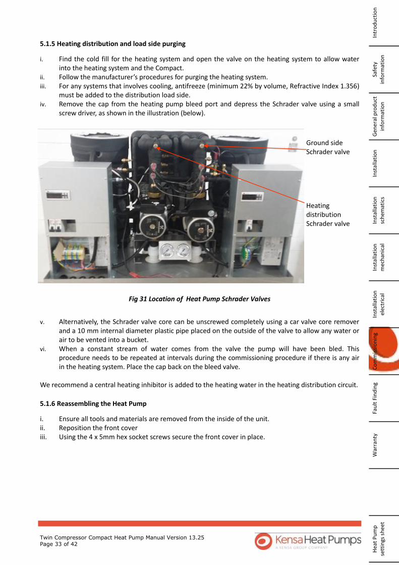
Twin Compressor Compact Heat Pump Manual Version 13.25 Page 33 of 42
5.1.6 Reassembling the Heat Pump
i. Ensure all tools and materials are removed from the inside of the unit. ii. Reposition the front cover iii. Using the 4 x 5mm hex socket screws secure the front cover in place.
5.1.5 Heating distribution and load side purging
i. Find the cold fill for the heating system and open the valve on the heating system to allow water into the heating system and the Compact. ii. Follow the manufacturer’s procedures for purging the heating system. iii. For any systems that involves cooling, antifreeze (minimum 22% by volume, Refractive Index 1.356) must be added to the distribution load side. iv. Remove the cap from the heating pump bleed port and depress the Schrader valve using a small screw driver, as shown in the illustration (below).
Heating distribution Schrader valve
Fig 31 Location of Heat Pump Schrader Valves
v. Alternatively, the Schrader valve core can be unscrewed completely using a car valve core remover and a 10 mm internal diameter plastic pipe placed on the outside of the valve to allow any water or air to be vented into a bucket. vi. When a constant stream of water comes from the valve the pump will have been bled. This procedure needs to be repeated at intervals during the commissioning procedure if there is any air in the heating system. Place the cap back on the bleed valve. We recommend a central heating inhibitor is added to the heating water in the heating distribution circuit.
Ground side Schrader valve
W
arra
nty
Fa
ult
Fin
din
g C
om
mis
sio
nin
g In
stal
lati
on
el
ectr
ical
In
stal
lati
on
m
ech
anic
al
Inst
alla
tio
n
sch
emat
ics
Inst
alla
tio
n
Gen
era
l pro
du
ct
info
rmat
ion
Sa
fety
info
rmat
ion
In
tro
du
ctio
n
Hea
t P
um
p
sett
ings
sh
eet

Twin Compressor Compact Heat Pump Manual Version 13.25 Page 34 of 42
5.2 Heat Pump Operation
Prior to use: - i. Turn off the power supply at the local isolator ii. Unscrew the 4 x 5mm hex socket screws on either side of the front panel (2 each side). Remove the
front panel. iii. Check that the ground pressure gauge reads at least 0.3 bar. If the pressure is lower than this, open
the mains cold water supply valve (fitted outside the case) fully until the gauge reads at least 1.8 bar, at which point a “click” will be heard. Close the mains cold water supply valve fully.
iv. Check that the heating distribution system pressure gauge reads at least 0.3 bar. If the pressure is lower than this, find the mains cold water supply valve and pressurize the system until the gauge reads at least 1.8 bar, at which point a “click” will be heard. Close the mains cold water supply valve fully. Reassemble the front panel taking care to ensure that the 4 x hex screws are located correctly. A purge pump can achieve pressures of 5 bar and it is acceptable that the ground arrays are left at this pressure.
v. Turn on the power supply at the local isolator and program the external timeclock / thermostat.
5.3 Turning the Heat Pump on for the first time.
i. Make sure the impellors in both the ground and heating distribution water pumps are free to turn by removing the stainless steel screws (if fitted) in the centre of each water pump and inserting a flat-bladed screwdriver to spin the impellor. Do not try to spin the impellor with the power on.
ii. Turn both the 6 Amp MCBs on to enable the controls and water pumps to operate. Operating this
MCB should result in a sudden sharp change in pressure on the underfloor pressure gauge and indi-cates that the pump is operational. Shortly after operating this MCB, the compressor contactor should engage. This will result in a sudden sharp change of pressure indicated on the ground array pressure gauge and this indicates that the ground array water pump is operational. DO NOT operate the compressor MCB until Kensa Heat Pumps has been contacted and flow has been confirmed around the system. Failure to do this will cause the unit to freeze and may invalidate the warranty.
iii. The controller display will read the temperature of the water returning from the heating system. If the error Tp is displayed, then the heat pump will not run until both heating distribution and ground circuits are above 1.8 bar pressure.
iv. The commissioning of the heat pump will be carried out remotely (via phone) by a Kensa commissioning engineer and a heat pump commissioning certificate and checklist issued on completion. Please contact Kensa Heat Pumps to book a commissioning call.
v. After commissioning and connection to the heating control system (with the power isolated) re-move the enable link between terminals 1 and 2.
Fig 32 Spinning the pump
Safety in
form
ation
G
ene
ral pro
du
ct in
form
ation
In
stallation
In
stallation
sch
ematics
Installatio
n
mech
anical
Installatio
n
electrical C
om
missio
nin
g Fau
lt Find
ing
Warran
ty
Heat P
um
p
settings sh
eet
Intro
du
ction
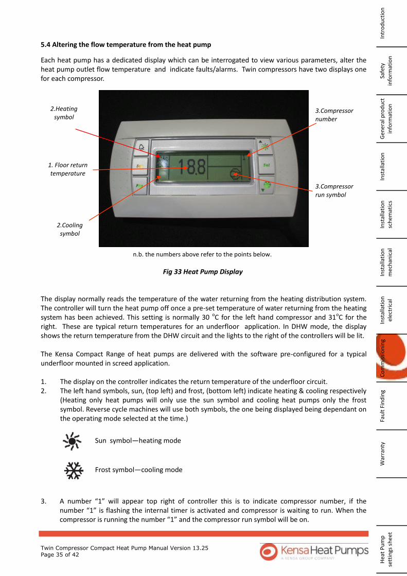
Twin Compressor Compact Heat Pump Manual Version 13.25 Page 35 of 42
5.4 Altering the flow temperature from the heat pump
Each heat pump has a dedicated display which can be interrogated to view various parameters, alter the heat pump outlet flow temperature and indicate faults/alarms. Twin compressors have two displays one for each compressor.
1. Floor return temperature
2.Heating symbol
2.Cooling symbol
3.Compressor number
3.Compressor run symbol
n.b. the numbers above refer to the points below.
Fig 33 Heat Pump Display
The display normally reads the temperature of the water returning from the heating distribution system. The controller will turn the heat pump off once a pre-set temperature of water returning from the heating system has been achieved. This setting is normally 30 oC for the left hand compressor and 31oC for the right. These are typical return temperatures for an underfloor application. In DHW mode, the display shows the return temperature from the DHW circuit and the lights to the right of the controllers will be lit. The Kensa Compact Range of heat pumps are delivered with the software pre-configured for a typical underfloor mounted in screed application. 1. The display on the controller indicates the return temperature of the underfloor circuit. 2. The left hand symbols, sun, (top left) and frost, (bottom left) indicate heating & cooling respectively
(Heating only heat pumps will only use the sun symbol and cooling heat pumps only the frost symbol. Reverse cycle machines will use both symbols, the one being displayed being dependant on the operating mode selected at the time.)
3. A number “1” will appear top right of controller this is to indicate compressor number, if the
number “1” is flashing the internal timer is activated and compressor is waiting to run. When the compressor is running the number “1” and the compressor run symbol will be on.
Sun symbol—heating mode
Frost symbol—cooling mode
W
arra
nty
Fa
ult
Fin
din
g C
om
mis
sio
nin
g In
stal
lati
on
el
ectr
ical
In
stal
lati
on
m
ech
anic
al
Inst
alla
tio
n
sch
emat
ics
Inst
alla
tio
n
Gen
era
l pro
du
ct
info
rmat
ion
Sa
fety
info
rmat
ion
In
tro
du
ctio
n
Hea
t P
um
p
sett
ings
sh
eet

Twin Compressor Compact Heat Pump Manual Version 13.25 Page 36 of 42
A flashing error code may appear if there is a fault with the heat pump, the most common will be: -
(See Fault Finding Section 6 for further details)
5.4.1 To read flow temperatures and refrigerant pressures Using the display it is possible to interrogate the heat pump to read flow temperatures and refrigerant pressures. The left hand display reads temperatures and refrigerant pressures in compressor one and the right hand controller compressor two. To read flow temperatures and refrigerant pressures, on each controller: - 1 Press and hold SEL until -/- is displayed 2 Press the UP arrow until -b- is displayed 3 Press SEL and b01 is displayed 4 Press SEL 5 Temperature of water returning from the underfloor is displayed = b01 6 Press SEL 7 Press the UP arrow once until b02 is displayed 8 Press SEL 9 Temperature of water returning from ground arrays is displayed = b02 10 Press SEL 11 Press the UP arrow once until b03 is displayed 12 Press SEL 13 Temperature of water going out to the ground arrays is displayed = b03 14 Press SEL 15 Press the UP arrow once until b04 is displayed 16 Press SEL 17 Refrigerant pressure (in Bar) is displayed = b04 18 Press SEL 19 Press PRG twice until S-P is displayed 20 Press and hold PRG until the display returns to normal 5.4.2 To change the heat pump return flow temperatures. Heat pumps are generally controlled on the return temperature from the heating distribution system and
Compressor running
Alarm Description
TP Low water pressure (ground or heating distribution)
HP High gas pressure caused by low or no flow on the heating distribution circuit.
LP Low gas pressure fault (can occur temporarily on first start up). Call Kensa Technical Department.
A1 Anti freeze alarm, ground getting too cold / insufficient anti freeze/ unit not commissioned correctly/ low flow around ground arrays.
Safety in
form
ation
G
ene
ral pro
du
ct in
form
ation
In
stallation
In
stallation
sch
ematics
Installatio
n
mech
anical
Installatio
n
electrical C
om
missio
nin
g Fau
lt Find
ing
Warran
ty
Heat P
um
p
settings sh
eet
Intro
du
ction
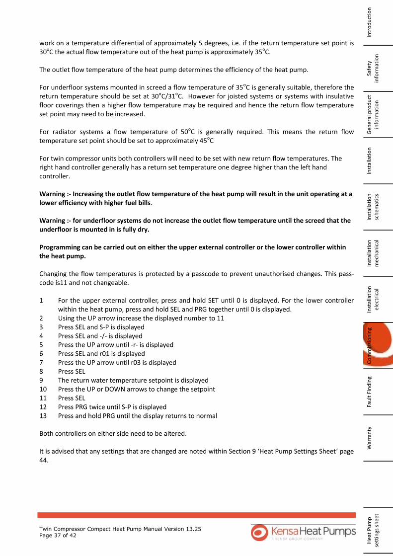
Twin Compressor Compact Heat Pump Manual Version 13.25 Page 37 of 42
work on a temperature differential of approximately 5 degrees, i.e. if the return temperature set point is 30oC the actual flow temperature out of the heat pump is approximately 35oC. The outlet flow temperature of the heat pump determines the efficiency of the heat pump. For underfloor systems mounted in screed a flow temperature of 35oC is generally suitable, therefore the return temperature should be set at 30oC/31oC. However for joisted systems or systems with insulative floor coverings then a higher flow temperature may be required and hence the return flow temperature set point may need to be increased. For radiator systems a flow temperature of 50oC is generally required. This means the return flow temperature set point should be set to approximately 45oC For twin compressor units both controllers will need to be set with new return flow temperatures. The right hand controller generally has a return set temperature one degree higher than the left hand controller. Warning :- Increasing the outlet flow temperature of the heat pump will result in the unit operating at a lower efficiency with higher fuel bills. Warning :- for underfloor systems do not increase the outlet flow temperature until the screed that the underfloor is mounted in is fully dry. Programming can be carried out on either the upper external controller or the lower controller within the heat pump. Changing the flow temperatures is protected by a passcode to prevent unauthorised changes. This pass-code is11 and not changeable. 1 For the upper external controller, press and hold SET until 0 is displayed. For the lower controller
within the heat pump, press and hold SEL and PRG together until 0 is displayed. 2 Using the UP arrow increase the displayed number to 11 3 Press SEL and S-P is displayed 4 Press SEL and -/- is displayed 5 Press the UP arrow until -r- is displayed 6 Press SEL and r01 is displayed 7 Press the UP arrow until r03 is displayed 8 Press SEL 9 The return water temperature setpoint is displayed 10 Press the UP or DOWN arrows to change the setpoint 11 Press SEL 12 Press PRG twice until S-P is displayed 13 Press and hold PRG until the display returns to normal Both controllers on either side need to be altered. It is advised that any settings that are changed are noted within Section 9 ‘Heat Pump Settings Sheet’ page 44.
W
arra
nty
Fa
ult
Fin
din
g C
om
mis
sio
nin
g In
stal
lati
on
el
ectr
ical
In
stal
lati
on
m
ech
anic
al
Inst
alla
tio
n
sch
emat
ics
Inst
alla
tio
n
Gen
era
l pro
du
ct
info
rmat
ion
Sa
fety
info
rmat
ion
In
tro
du
ctio
n
Hea
t P
um
p
sett
ings
sh
eet
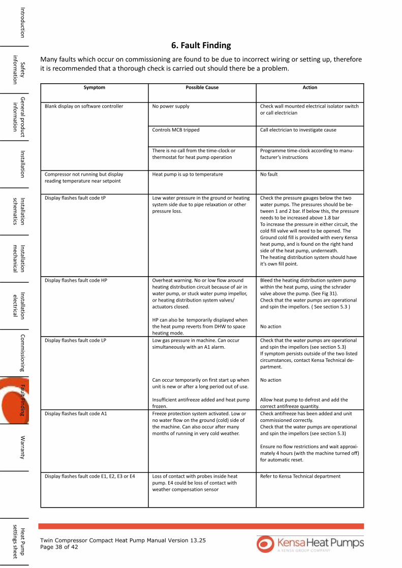
Twin Compressor Compact Heat Pump Manual Version 13.25 Page 38 of 42
6. Fault Finding
Many faults which occur on commissioning are found to be due to incorrect wiring or setting up, therefore it is recommended that a thorough check is carried out should there be a problem.
Symptom Possible Cause Action
Blank display on software controller No power supply Check wall mounted electrical isolator switch or call electrician
Controls MCB tripped Call electrician to investigate cause
There is no call from the time-clock or thermostat for heat pump operation
Programme time-clock according to manu-facturer’s instructions
Compressor not running but display reading temperature near setpoint
Heat pump is up to temperature No fault
Display flashes fault code tP Low water pressure in the ground or heating system side due to pipe relaxation or other pressure loss.
Check the pressure gauges below the two water pumps. The pressures should be be-tween 1 and 2 bar. If below this, the pressure needs to be increased above 1.8 bar To increase the pressure in either circuit, the cold fill valve will need to be opened. The Ground cold fill is provided with every Kensa heat pump, and is found on the right hand side of the heat pump, underneath. The heating distribution system should have it’s own fill point.
Display flashes fault code HP Overheat warning. No or low flow around heating distribution circuit because of air in water pump, or stuck water pump impellor, or heating distribution system valves/actuators closed. HP can also be temporarily displayed when the heat pump reverts from DHW to space heating mode.
Bleed the heating distribution system pump within the heat pump, using the schrader valve above the pump. (See Fig 31). Check that the water pumps are operational and spin the impellors. ( See section 5.3 ) No action
Display flashes fault code LP Low gas pressure in machine. Can occur simultaneously with an A1 alarm. Can occur temporarily on first start up when unit is new or after a long period out of use. Insufficient antifreeze added and heat pump frozen.
Check that the water pumps are operational and spin the impellors (see section 5.3) If symptom persists outside of the two listed circumstances, contact Kensa Technical de-partment. No action Allow heat pump to defrost and add the correct antifreeze quantity.
Display flashes fault code A1 Freeze protection system activated. Low or no water flow on the ground (cold) side of the machine. Can also occur after many months of running in very cold weather.
Check antifreeze has been added and unit commissioned correctly. Check that the water pumps are operational and spin the impellors (see section 5.3) Ensure no flow restrictions and wait approxi-mately 4 hours (with the machine turned off) for automatic reset.
Display flashes fault code E1, E2, E3 or E4 Loss of contact with probes inside heat pump. E4 could be loss of contact with weather compensation sensor
Refer to Kensa Technical department
Safety in
form
ation
G
ene
ral pro
du
ct in
form
ation
In
stallation
In
stallation
sch
ematics
Installatio
n
mech
anical
Installatio
n
electrical C
om
missio
nin
g Fau
lt Find
ing
Warran
ty
Heat P
um
p
settings sh
eet
Intro
du
ction
Twin Compressor Compact Heat Pump Manual Version 13.25 Page 39 of 42
7. Warranty
The Kensa Compact Ground Source heat pump is designed and built to the highest standard and as such is guaranteed for 5 years for parts from the date of commissioning or 5 ½ years from the date of manufacture (excluding the internal water pumps and electrical components), whichever is shorter. Internal water pumps (ground and load side) and electrical components are guaranteed for 2 years for parts from the date of commissioning or 2 ½ years from the date of manufacturer, whichever is shorter. 7.1 Terms and Conditions. 7.1.1 Persons covered by the Warranty The Warranty applies to the original purchaser and any subsequent owner of the item. 7.1.2 Validity period of the Warranty The guarantee period (excluding the water pumps and electrical components) is five years calculated from the commissioning date stated on the commissioning certificate or 5 ½ years from the date of manufacture, whichever is shorter. For the water pumps and electrical components it is 2 years from the commissioning date stated on the commissioning certificate or 2 ½ years from the date of manufacture, whichever is shorter. 7.1.3 Scope Kensa Heat Pumps Ltd warrants to the original purchaser (“Buyer”) that all parts (“Parts”) of the Kensa Compact Ground Source Heat Pump, excluding accessories, shall be merchantable and free from defects in materials and workmanship appearing under normal working conditions. Kensa Heat Pumps Ltd will, at its option and without charge to the Buyer, replace or repair any Parts which cause the Kensa Compact Ground Source Heat Pump to be inoperable; however, if Kensa Heat Pumps Ltd elects to provide replacement Parts, it shall not be obligated to install such replacement Parts and the Buyer shall be responsible for all other costs, including, but not limited to, shipping fees and ex-penses. The warranty applies to faults originating inside the item. 7.1.4 General exceptions Compensation is not provided for: - consequential losses - damage caused by normal wear and tear, inadequate maintenance or care - damage caused by freezing - damage of the unit due to non-approved or incorrect quantities of antifreeze being used in the ground side, incorrect flowrates or air in the system - damage caused by power surges, incorrect supply voltage or lightning strikes. - cost of inspecting, adjusting or cleaning the item, unless this relates to damage that is eligible for compensation -minor damage (e.g. scratches and marks) that does not affect the operation of the item -damage covered by insurance -indirect damage -loss or damage caused by gross negligence or intent, misappropriation, fraud or similar crime against property, breach of trust or fraudulent conversion. -products that have been: altered; subject to misuse, negligence, accidental damage, abnormal use or service; operated or installed in a manner contrary to Kensa Heat Pumps Ltd published or written instructions.
W
arra
nty
Fa
ult
Fin
din
g C
om
mis
sio
nin
g In
stal
lati
on
el
ectr
ical
In
stal
lati
on
m
ech
anic
al
Inst
alla
tio
n
sch
emat
ics
Inst
alla
tio
n
Gen
era
l pro
du
ct
info
rmat
ion
Sa
fety
info
rmat
ion
In
tro
du
ctio
n
Hea
t P
um
p
sett
ings
sh
eet

Twin Compressor Compact Heat Pump Manual Version 13.25 Page 40 of 42
-products subjected to abrasion or corrosion -products operated in connection with any liquid source that contains impurities which are corrosive to copper -products operated in a temperature range inconsistent with Kensa Heat Pumps Ltd’s published or written recommendations 7.1.5 Care of Duty The product must be handled with normal care and attention to minimise the risk of damage or loss. 7.1.6 In the event of Damage The installing contractor (“Contractor”),or, if the installing Contractor is not available, Kensa Heat Pumps Ltd must be notified of any damage immediately and no later than six months after you first became aware of the damage. The commissioning certificate received on installation should be appended to the claim. If a claim for compensation is made after the deadline specified above or if a commissioning certificate cannot be produced, the guarantee shall not apply. 7.1.7 Replacement Parts Kensa Heat Pumps Ltd’s warranty obligations with respect to replacement parts are identical to those with respect to original parts; provided, however, in no event shall the warranty term for such replacement parts extend beyond the term established by the commencement date (i.e. commissioning date) of the warranty under which Kensa Heat Pumps Ltd was obligated to provide such replacement parts. Kensa Heat Pumps Ltd shall have the right to retain possession or dispose of any parts replaced by it.
Safety in
form
ation
G
ene
ral pro
du
ct in
form
ation
In
stallation
In
stallation
sch
ematics
Installatio
n
mech
anical
Installatio
n
electrical C
om
missio
nin
g Fau
lt Find
ing
Warran
ty
Heat P
um
p
settings sh
eet
Intro
du
ction
Twin Compressor Compact Heat Pump Manual Version 13.25 Page 41 of 42
This page is left intentionally blank
W
arra
nty
Fa
ult
Fin
din
g C
om
mis
sio
nin
g In
stal
lati
on
el
ectr
ical
In
stal
lati
on
m
ech
anic
al
Inst
alla
tio
n
sch
emat
ics
Inst
alla
tio
n
Gen
era
l pro
du
ct
info
rmat
ion
Sa
fety
info
rmat
ion
In
tro
du
ctio
n
Hea
t P
um
p
sett
ings
sh
eet

Twin Compressor Compact Heat Pump Manual Version 13.25 Page 42 of 42
8. Heat Pump Settings Sheet
Safety in
form
ation
G
ene
ral pro
du
ct in
form
ation
In
stallation
In
stallation
sch
ematics
Installatio
n
mech
anical
Installatio
n
electrical C
om
missio
nin
g Fau
lt Find
ing
Warran
ty
Heat P
um
p
settings sh
eet
Intro
du
ction
Type of ground arrays
Ground Arrays purged
Ground arrays leak tested according to BS805 Section 11.3.3.4
Yes / No
Antifreeze quantity
Antifreeze concentration Sample 1 Sample 2
Serial Number
Visual Inspection
Feet level on floor
Visual check of site wiring
Software operating
Software errors
Heating Status
Ground water pressure
Underfloor water pressure
Make of underfloor heating
Manifolds
Any UFH water pumps
Control philosophy
B01 underfloor return temperature
B02 ground return temperature
B03 ground feed temperature
B04 evaporating pressure
Comments:
Installed by:- Date:- Tel:-