tv transmittersrvr elettronica s.p.a. via del fonditore, 2/2c:ona)ndustriale2overis...
TRANSCRIPT

RVR Elettronica S.p.A.Via del Fonditore, 2/2c
TV transmitters
MODEL OUTPUT POWER CONSUMPTION POWER CONSUMPTION WEIGHT DIMENSIONS
UHF VHF POWER BLACK LEVEL GREY LEVEL W-D-H (mm)
STU 25 STV 25 500 W 1200 W 1000 W Approx. 160Kg 590-1200-1300
STU 31 STV 31 1.000 W 2700 W 2100 W Approx. 165Kg 590-1200-1300
STU 32 STV 32 2.000 W 5600 W 4300 W Approx. 200Kg 590-1200-1300
STU 33 STV 33 3.000 W 7800 W 6200 W Approx. 380Kg 590-1200-1920
STU 34 STV 34 4.000 W 9900 W 8300 W Approx. 420Kg 590-1200-1920
STU 35 STV 35 5.000 W 12500 W 10000 W Approx. 460Kg 590-1200-1920
Table 1
Technical specifi cations Parameters Values GENERALS
Altitude
RF SECTION SPECIFICATIONS
Standard All standards Intermodulation
TRANSMISSION CHARACTERISTICS
Intercarrier noise
Parameters Values VISION
Return loss
SOUND
METERING
PROTECTION CIRCUIT Over current
VSWR REMOTE CONTROL Parallel on, off, alarms
Revision: 03/09

RVR Elettronica S.p.A. • Phone +39 051 6010506 • Fax +39 051 6011104 • e-mail: [email protected] • Web: http://www.rvr.it
TV exciters/transmitters/repeaters TV exciters/transmitters/repeaters
> Precorrection with three slope control on front panel. > Predisposition to professional precorrector, it furnish more performance at 10W. > Synthesized oscillator with 25Hz step (precision 1Hz). > BLUE VIDEO integrates a timer switch for automatic commuta tion between two externals IF sources (DUAL CAST mode). > Optionally BLUE VIDEO can be used as analog or digital repeater.
> Stereo version available.
> Internal Modular System. > Forced air cooling. > Low noise.
> Low cost.
> Precorrezione con comando a tre pendenze sul pannello frontale. > Predisposizione a precorrettore professionale, fornisce una miglio- re prestazione a 10W. > Oscillatore sintetizzato a step di 25Hz (precisione 1Hz). > BLUE VIDEO dispone di un interruttore temporizzato per la com- mutazione automatica tra due sorgenti esterne IF (modalità DUAL CAST).
> BLUE VIDEO può essere utilizzato eventualmente anche come ripetitore analogico o digitale.
> Disponibile in versione stereo.
> Sistema Modulare Interno. > Raffreddamento ad aria forzata. > Basse emissioni sonore.
> Basso costo.
BLUE VIDEO front view
Features - Caratteristiche
Preliminary version

RVR Elettronica S.p.A.Via del Fonditore, 2/2cZona Industriale Roveri • 40138 Bologna • ItalyPhone: +39 051 6010506 • Fax: +39 051 6011104e-mail: [email protected] • web: http://www.rvr.it
ISO 9001:2000 certified since 2000
BLUE VIDEO rear view
Technical specifications
All pictures are RVR’s property and they are only indicative and not binding. The pictures can be modified without notice.
These are general specifications. They show typical values and are subject to change without notice.Revision: 03/09
Parameters Values GENERALS Frequency range 470÷860 MHz Output power 5 Watt (Class A) ; 10 Watt (Class A/B) Standard B,G,M,I,K PAL/NTSC Power supply 100-250 Vac 47-63 Hz Power consumption 80VA Operating temperature 0 ÷ +45 °C IMD (-8; -10; -16 dB)
5 W power amplifier -60 dB @ 2 W (pre-correction off)
IMD (-8; -10; -16 dB) -65 dB @ 2 W (pre-correction on) IMD (-8; -10; -16 dB)
10 W power amplifier -52 dB @ 10W(pre-correction off)
IMD (-8; -10; -16 dB) -60 dB @ 10W(pre-correction on) Power stability ± 0,5 dB Harmonics suppression <- 60 dBc (with output filter) Video connector BNC female Audio connector Mini XLR Enabling IN/OUT ed ALC connector 15 pin type D RS 232 connector 9 pin type D VIDEO Input level 1 Vpp / 75Ω Differential gain < 5% Differential phase < 5° Group delay ± 50 nS Level frequency response ± 0,5 dB Signal to noise ratio <-60 dB (weighted) AUDIO Input level 0 dBm ± 6dB / 600Ω (optional 10 KΩ) Level frequency response ± 0,3 dB (30Hz±15Khz) Harmonic distortions < 0,4 % Signal to noise ratio > 65 dB (30Hz±15Khz not weighted RMS with de-emphasis) PROTECTIONS Max VSWR Max Idc Max Temperature Max output power DIMENSIONS Dimensions Std. 19” frame, 29,34 H (1,15”) x 483 (19”) W x 550 (21,65”) D mm.
TV exciters/transmitters/repeaters
RVR Elettronica S.p.A. • Phone +39 051 6010506 • Fax +39 051 6011104 • e-mail: [email protected] • Web: http://www.rvr.it
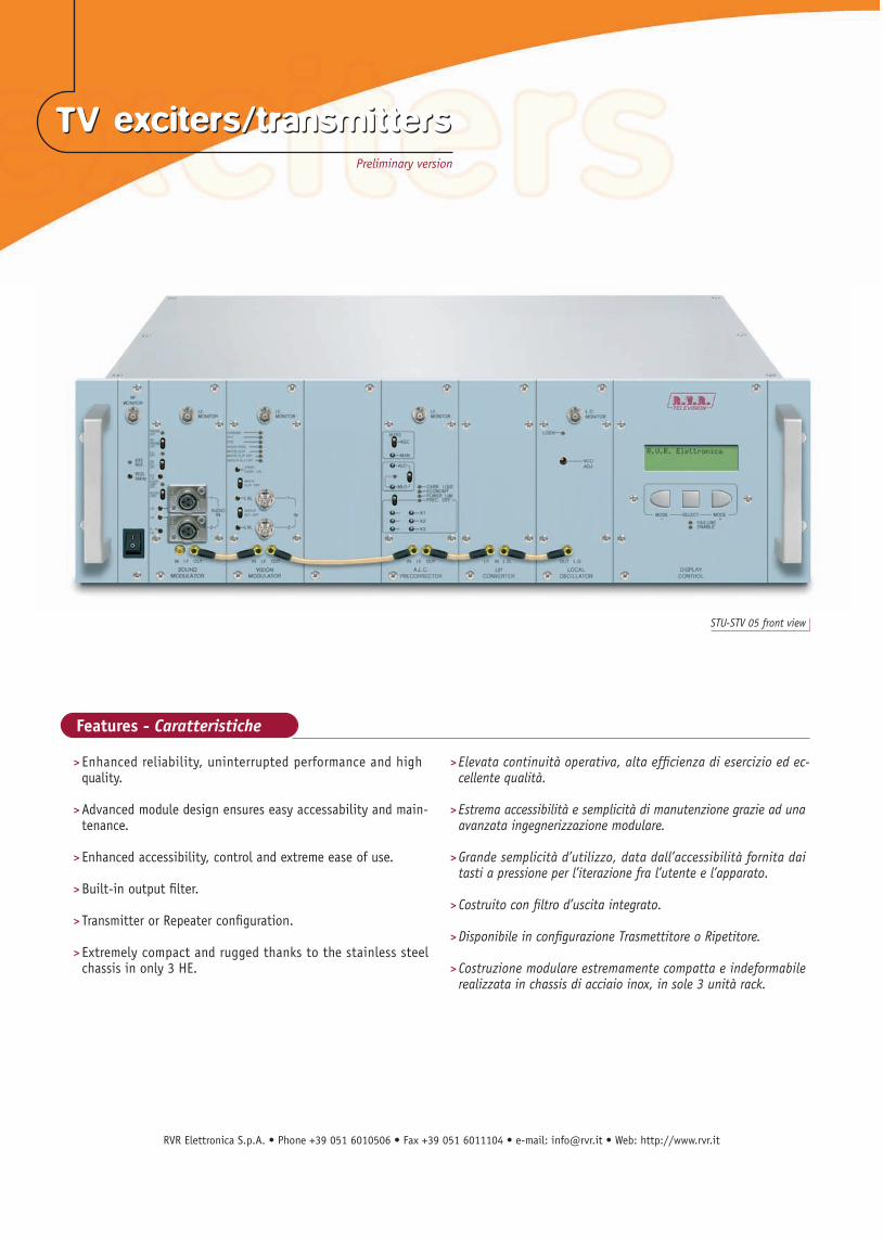
> Enhanced reliability, uninterrupted performance and high quality.
> Advanced module design ensures easy accessability and main- tenance. > Enhanced accessibility, control and extreme ease of use. > Built-in output filter. > Transmitter or Repeater configuration.
> Extremely compact and rugged thanks to the stainless steel chassis in only 3 HE.
> Elevata continuità operativa, alta efficienza di esercizio ed ec- cellente qualità.
> Estrema accessibilità e semplicità di manutenzione grazie ad una avanzata ingegnerizzazione modulare. > Grande semplicità d’utilizzo, data dall’accessibilità fornita dai tasti a pressione per l’iterazione fra l’utente e l’apparato. > Costruito con filtro d’uscita integrato. > Disponibile in configurazione Trasmettitore o Ripetitore.
> Costruzione modulare estremamente compatta e indeformabile realizzata in chassis di acciaio inox, in sole 3 unità rack.
STU-STV 05 front view
Features - Caratteristiche
TV exciters/transmitters TV exciters/transmitters Preliminary version
RVR Elettronica S.p.A.Via del Fonditore, 2/2cZona Industriale Roveri • 40138 Bologna • ItalyPhone: +39 051 6010506 • Fax: +39 051 6011104e-mail: [email protected] • web: http://www.rvr.it
ISO 9001:2000 certified since 2000
Technical specifications
All pictures are RVR’s property and they are only indicative and not binding. The pictures can be modified without notice.
These are general specifications. They show typical values and are subject to change without notice.Revision: 03/09
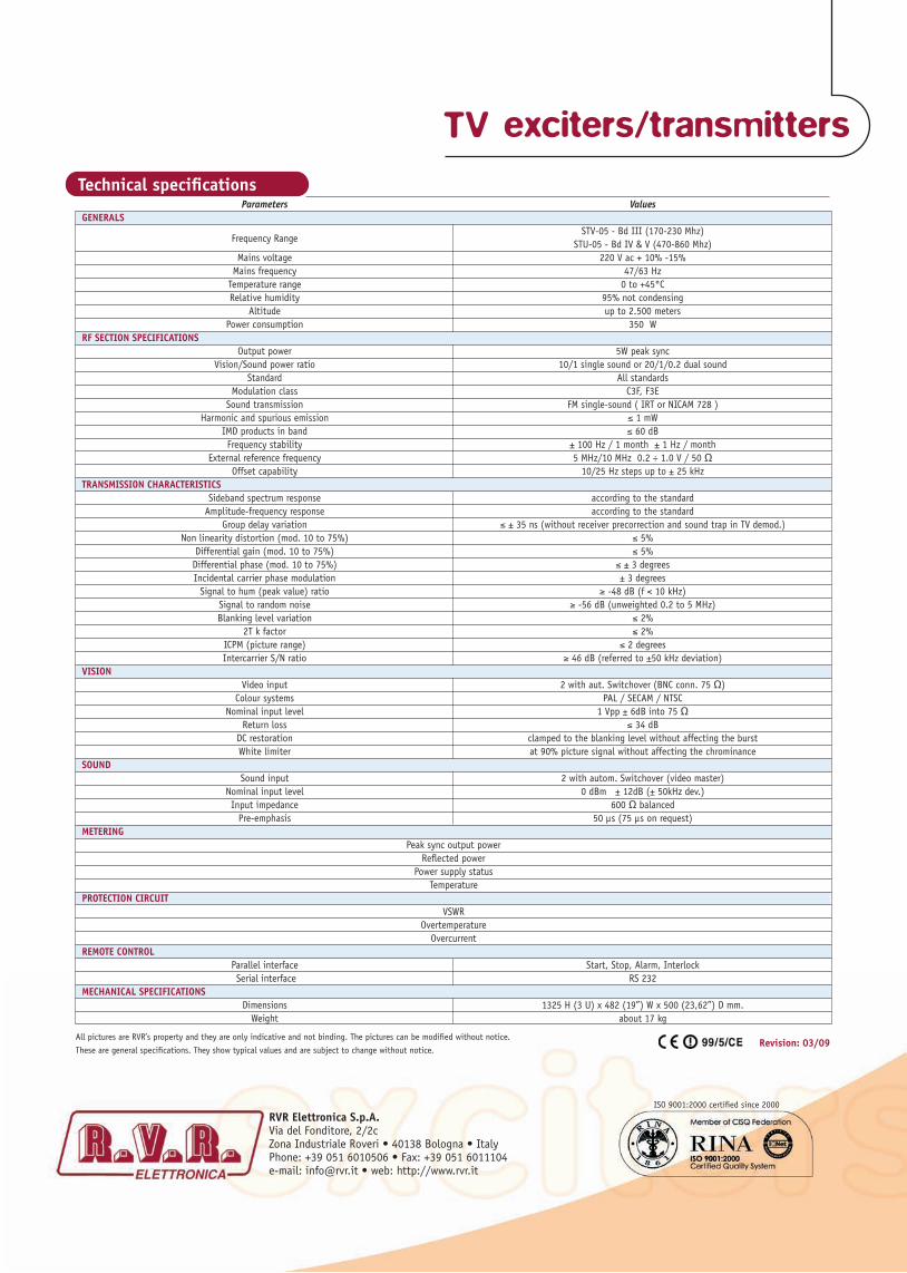
Parameters Values GENERALS
Frequency Range STV-05 - Bd III (170-230 Mhz)
STU-05 - Bd IV & V (470-860 Mhz) Mains voltage 220 V ac + 10% -15% Mains frequency 47/63 Hz Temperature range 0 to +45°C Relative humidity 95% not condensing Altitude up to 2.500 meters Power consumption 350 W RF SECTION SPECIFICATIONS Output power 5W peak sync Vision/Sound power ratio 10/1 single sound or 20/1/0.2 dual sound Standard All standards Modulation class C3F, F3E Sound transmission FM single-sound ( IRT or NICAM 728 ) Harmonic and spurious emission ≤ 1 mW IMD products in band ≤ 60 dB Frequency stability ± 100 Hz / 1 month ± 1 Hz / month External reference frequency 5 MHz/10 MHz 0.2 ÷ 1.0 V / 50 Ω Offset capability 10/25 Hz steps up to ± 25 kHz TRANSMISSION CHARACTERISTICS Sideband spectrum response according to the standard Amplitude-frequency response according to the standard Group delay variation ≤ ± 35 ns (without receiver precorrection and sound trap in TV demod.) Non linearity distortion (mod. 10 to 75%) ≤ 5% Differential gain (mod. 10 to 75%) ≤ 5% Differential phase (mod. 10 to 75%) ≤ ± 3 degrees Incidental carrier phase modulation ± 3 degrees Signal to hum (peak value) ratio ≥ -48 dB (f < 10 kHz) Signal to random noise ≥ -56 dB (unweighted 0.2 to 5 MHz) Blanking level variation ≤ 2% 2T k factor ≤ 2% ICPM (picture range) ≤ 2 degrees Intercarrier S/N ratio ≥ 46 dB (referred to ±50 kHz deviation) VISION Video input 2 with aut. Switchover (BNC conn. 75 Ω) Colour systems PAL / SECAM / NTSC Nominal input level 1 Vpp ± 6dB into 75 Ω Return loss ≤ 34 dB DC restoration clamped to the blanking level without affecting the burst White limiter at 90% picture signal without affecting the chrominance SOUND Sound input 2 with autom. Switchover (video master) Nominal input level 0 dBm ± 12dB (± 50kHz dev.) Input impedance 600 Ω balanced Pre-emphasis 50 μs (75 μs on request) METERING Peak sync output power Reflected power Power supply status Temperature PROTECTION CIRCUIT VSWR Overtemperature Overcurrent REMOTE CONTROL Parallel interface Start, Stop, Alarm, Interlock Serial interface RS 232 MECHANICAL SPECIFICATIONS Dimensions 1325 H (3 U) x 482 (19”) W x 500 (23,62”) D mm. Weight about 17 kg
TV exciters/transmitters
RVR Elettronica S.p.A. • Phone +39 051 6010506 • Fax +39 051 6011104 • e-mail: [email protected] • Web: http://www.rvr.it
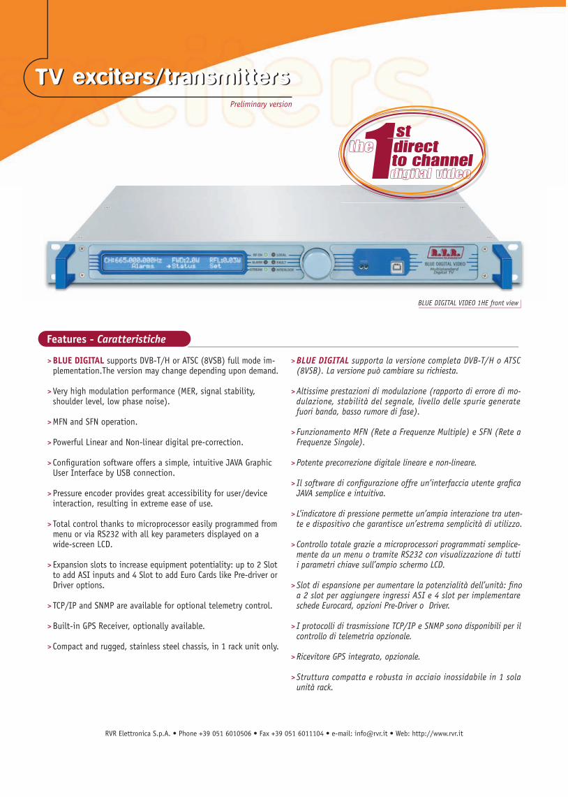
> BLUE DIGITAL supports DVB-T/H or ATSC (8VSB) full mode im- plementation.The version may change depending upon demand. > Very high modulation performance (MER, signal stability, shoulder level, low phase noise). > MFN and SFN operation.
> Powerful Linear and Non-linear digital pre-correction. > Confi guration software offers a simple, intuitive JAVA Graphic User Interface by USB connection. > Pressure encoder provides great accessibility for user/device interaction, resulting in extreme ease of use. > Total control thanks to microprocessor easily programmed from menu or via RS232 with all key parameters displayed on a wide-screen LCD.
> Expansion slots to increase equipment potentiality: up to 2 Slot to add ASI inputs and 4 Slot to add Euro Cards like Pre-driver or Driver options. > TCP/IP and SNMP are available for optional telemetry control.
> Built-in GPS Receiver, optionally available.
> Compact and rugged, stainless steel chassis, in 1 rack unit only.
> BLUE DIGITAL supporta la versione completa DVB-T/H o ATSC (8VSB). La versione può cambiare su richiesta.
> Altissime prestazioni di modulazione (rapporto di errore di mo- dulazione, stabilità del segnale, livello delle spurie generate fuori banda, basso rumore di fase). > Funzionamento MFN (Rete a Frequenze Multiple) e SFN (Rete a Frequenze Singole).
> Potente precorrezione digitale lineare e non-lineare. > Il software di confi gurazione offre un’interfaccia utente grafi ca JAVA semplice e intuitiva. > L’indicatore di pressione permette un’ampia interazione tra uten- te e dispositivo che garantisce un’estrema semplicità di utilizzo. > Controllo totale grazie a microprocessori programmati semplice- mente da un menu o tramite RS232 con visualizzazione di tutti i parametri chiave sull’ampio schermo LCD.
> Slot di espansione per aumentare la potenzialità dell’unità: fi no a 2 slot per aggiungere ingressi ASI e 4 slot per implementare schede Eurocard, opzioni Pre-Driver o Driver. > I protocolli di trasmissione TCP/IP e SNMP sono disponibili per il controllo di telemetria opzionale.
> Ricevitore GPS integrato, opzionale.
> Struttura compatta e robusta in acciaio inossidabile in 1 sola unità rack.
BLUE DIGITAL VIDEO 1HE front view
Features - Caratteristiche
TV exciters/transmitters TV exciters/transmitters Preliminary version
RVR Elettronica S.p.A.Via del Fonditore, 2/2cZona Industriale Roveri • 40138 Bologna • ItalyPhone: +39 051 6010506 • Fax: +39 051 6011104e-mail: [email protected] • web: http://www.rvr.it
ISO 9001:2000 certifi ed since 2000
Technical specifi cations
All pictures are RVR’s property and they are only indicative and not binding. The pictures can be modifi ed without notice.
These are general specifi cations. They show typical values and are subject to change without notice. Revision: 03/09
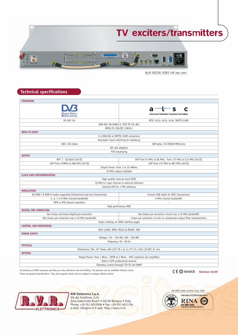
STANDARDS
EN 300 744 ATSC: A/53, A/54, A/64, SMPTE-310M DVB-ASI: EN 50083-9, ETSI TR 101 891 MPEG-TS: ISO/IEC 13818-1 MPEG-TS INPUT 2 x DVB-ASI or SMPTE-310M connectors Automatic input switching for redudancy 188 / 204 bytes 188 bytes, 19.392658 Mbits/sec Bit rate adaption PCR restamping OUTPUT VHF I - III Band (50 Ω) VHF from 57 MHz to 85 MHz, from 177 MHz to 213 MHz (50 Ω) UHF from 470MHz to 860 MHz (50 Ω) UHF from 473 MHz to 887 MHz (50 Ω) Output Power: from 1 to 10 mWrms 10 MHz output available CLOCK AND SYNCHRONIZATION High quality internal clock OCXO 10 MHz 0.1 ppm internal or external reference Internal GPS for 1 PPS reference MODULATION All DVB-T & DVB-H modes supported (hierarchical and non hierarchical) 8 levels VSB trellis for ATSC transmission 5, 6, 7 or 8 MHz channel bandwidth 6 MHz channel bandwidth MFN or SFN network operation - High performance MER DIGITAL PRE-CORRECTION Non-linear and linear digital pre-correction Non-linear pre-correction circuit over a 15 MHz bandwidth Non-linear pre-correction over a 20 MHz bandwidth Linear pre-correction circuits to compensate output fi lter characteristics Grapic settings on JAVA interface pages CONTROL AND MONITORING RJ45 (LAN), IRDA, RS232 & RS485, USB POWER SUPPLY Voltage: 110 - 130 VAC; 200 - 250 VAC Frequency: 50 - 60 Hz PHYSICAL Dimensions: Std. 19” frame, 483 (19”) W x 44 (1,73”) H x 503 (19,08”) D, mm. OPTIONS Output Power: from 1 Wrms - DVTB to 2 Wrms - ATSC (optional slot amplifi er) Built-in GPS professional receiver Telemetry control through TCP-IP and SNMP
BLUE DIGITAL VIDEO 1HE rear view
TV exciters/transmitters
RVR Elettronica S.p.A. • Phone +39 051 6010506 • Fax +39 051 6011104 • e-mail: [email protected] • Web: http://www.rvr.it
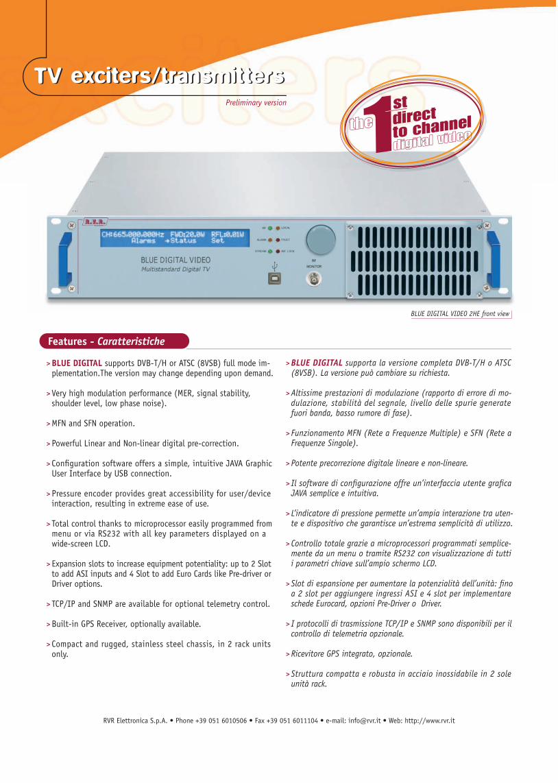
BLUE DIGITAL VIDEO 2HE front view
Features - Caratteristiche
> BLUE DIGITAL supports DVB-T/H or ATSC (8VSB) full mode im- plementation.The version may change depending upon demand. > Very high modulation performance (MER, signal stability, shoulder level, low phase noise). > MFN and SFN operation.
> Powerful Linear and Non-linear digital pre-correction. > Confi guration software offers a simple, intuitive JAVA Graphic User Interface by USB connection. > Pressure encoder provides great accessibility for user/device interaction, resulting in extreme ease of use. > Total control thanks to microprocessor easily programmed from menu or via RS232 with all key parameters displayed on a wide-screen LCD.
> Expansion slots to increase equipment potentiality: up to 2 Slot to add ASI inputs and 4 Slot to add Euro Cards like Pre-driver or Driver options. > TCP/IP and SNMP are available for optional telemetry control.
> Built-in GPS Receiver, optionally available.
> Compact and rugged, stainless steel chassis, in 2 rack units only.
> BLUE DIGITAL supporta la versione completa DVB-T/H o ATSC (8VSB). La versione può cambiare su richiesta.
> Altissime prestazioni di modulazione (rapporto di errore di mo- dulazione, stabilità del segnale, livello delle spurie generate fuori banda, basso rumore di fase). > Funzionamento MFN (Rete a Frequenze Multiple) e SFN (Rete a Frequenze Singole).
> Potente precorrezione digitale lineare e non-lineare. > Il software di confi gurazione offre un’interfaccia utente grafi ca JAVA semplice e intuitiva. > L’indicatore di pressione permette un’ampia interazione tra uten- te e dispositivo che garantisce un’estrema semplicità di utilizzo. > Controllo totale grazie a microprocessori programmati semplice- mente da un menu o tramite RS232 con visualizzazione di tutti i parametri chiave sull’ampio schermo LCD.
> Slot di espansione per aumentare la potenzialità dell’unità: fi no a 2 slot per aggiungere ingressi ASI e 4 slot per implementare schede Eurocard, opzioni Pre-Driver o Driver. > I protocolli di trasmissione TCP/IP e SNMP sono disponibili per il controllo di telemetria opzionale.
> Ricevitore GPS integrato, opzionale.
> Struttura compatta e robusta in acciaio inossidabile in 2 sole unità rack.
TV exciters/transmitters TV exciters/transmitters Preliminary version

RVR Elettronica S.p.A.Via del Fonditore, 2/2cZona Industriale Roveri • 40138 Bologna • ItalyPhone: +39 051 6010506 • Fax: +39 051 6011104e-mail: [email protected] • web: http://www.rvr.it
ISO 9001:2000 certifi ed since 2000
All pictures are RVR’s property and they are only indicative and not binding. The pictures can be modifi ed without notice.
These are general specifi cations. They show typical values and are subject to change without notice. Revision: 03/09
Technical specifi cations
STANDARDS
EN 300 744 ATSC: A/53, A/54, A/64, SMPTE-310M DVB-ASI: EN 50083-9, ETSI TR 101 891 MPEG-TS: ISO/IEC 13818-1 MPEG-TS INPUT 2 x DVB-ASI or SMPTE-310M connectors Automatic input switching for redudancy 188 / 204 bytes 188 bytes, 19.392658 Mbits/sec Bit rate adaption PCR restamping OUTPUT VHF I - III Band (50 Ω) VHF from 57 MHz to 85 MHz, from 177 MHz to 213 MHz (50 Ω) UHF from 470MHz to 860 MHz (50 Ω) UHF from 473 MHz to 887 MHz (50 Ω) Output power up to 40 W 10 MHz output available CLOCK AND SYNCHRONIZATION High quality internal clock OCXO 10 MHz 0.1 ppm internal or external reference Internal GPS for 1 PPS reference MODULATION All DVB-T & DVB-H modes supported (hierarchical and non hierarchical) 8 levels VSB trellis for ATSC transmission 5, 6, 7 or 8 MHz channel bandwidth 6 MHz channel bandwidth MFN or SFN network operation - High performance MER DIGITAL PRE-CORRECTION Non-linear and linear digital pre-correction Non-linear pre-correction circuit over a 15 MHz bandwidth Non-linear pre-correction over a 20 MHz bandwidth Linear pre-correction circuits to compensate output fi lter characteristics Grapic settings on JAVA interface pages CONTROL AND MONITORING RJ45 (LAN), IRDA, RS232 & RS485, USB POWER SUPPLY Voltage: 90 - 250 VAC Frequency: 50 - 60 Hz PHYSICAL Dimensions: Std. 19” frame, 483 (19”) W x 88 (3,46”) H x 503 (19,08”) D, mm. OPTIONS Built-in GPS professional receiver Telemetry control through TCP-IP and SNMP
BLUE DIGITAL VIDEO 2HE rear view
TV exciters/transmitters
RVR Elettronica S.p.A. • Phone +39 051 6010506 • Fax +39 051 6011104 • e-mail: [email protected] • Web: http://www.rvr.it
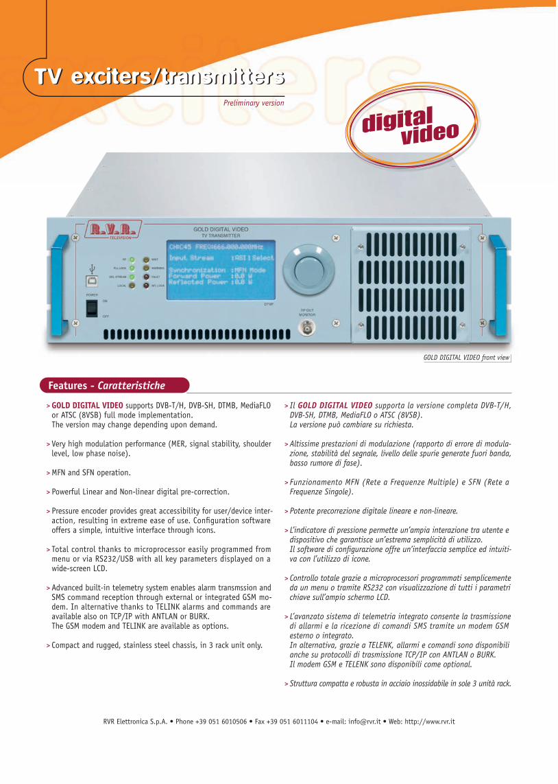
> GOLD DIGITAL VIDEO supports DVB-T/H, DVB-SH, DTMB, MediaFLO or ATSC (8VSB) full mode implementation. The version may change depending upon demand. > Very high modulation performance (MER, signal stability, shoulder level, low phase noise).
> MFN and SFN operation.
> Powerful Linear and Non-linear digital pre-correction. > Pressure encoder provides great accessibility for user/device inter- action, resulting in extreme ease of use. Confi guration software offers a simple, intuitive interface through icons. > Total control thanks to microprocessor easily programmed from menu or via RS232/USB with all key parameters displayed on a wide-screen LCD. > Advanced built-in telemetry system enables alarm transmssion and SMS command reception through external or integrated GSM mo- dem. In alternative thanks to TELINK alarms and commands are available also on TCP/IP with ANTLAN or BURK. The GSM modem and TELINK are available as options. > Compact and rugged, stainless steel chassis, in 3 rack unit only.
> Il GOLD DIGITAL VIDEO supporta la versione completa DVB-T/H, DVB-SH, DTMB, MediaFLO o ATSC (8VSB). La versione può cambiare su richiesta. > Altissime prestazioni di modulazione (rapporto di errore di modula- zione, stabilità del segnale, livello delle spurie generate fuori banda, basso rumore di fase).
> Funzionamento MFN (Rete a Frequenze Multiple) e SFN (Rete a Frequenze Singole).
> Potente precorrezione digitale lineare e non-lineare. > L’indicatore di pressione permette un’ampia interazione tra utente e dispositivo che garantisce un’estrema semplicità di utilizzo. Il software di confi gurazione offre un’interfaccia semplice ed intuiti- va con l’utilizzo di icone.
> Controllo totale grazie a microprocessori programmati semplicemente da un menu o tramite RS232 con visualizzazione di tutti i parametri chiave sull’ampio schermo LCD.
> L’avanzato sistema di telemetria integrato consente la trasmissione di allarmi e la ricezione di comandi SMS tramite un modem GSM esterno o integrato. In alternativa, grazie a TELENK, allarmi e comandi sono disponibili anche su protocolli di trasmissione TCP/IP con ANTLAN o BURK. Il modem GSM e TELENK sono disponibili come optional.
> Struttura compatta e robusta in acciaio inossidabile in sole 3 unità rack.
Features - Caratteristiche
TV exciters/transmitters TV exciters/transmitters
GOLD DIGITAL VIDEO front view
Preliminary version
RVR Elettronica S.p.A.Via del Fonditore, 2/2cZona Industriale Roveri • 40138 Bologna • ItalyPhone: +39 051 6010506 • Fax: +39 051 6011104e-mail: [email protected] • web: http://www.rvr.it
ISO 9001:2000 certifi ed since 2000
Technical specifi cations
All pictures are RVR’s property and they are only indicative and not binding. The pictures can be modifi ed without notice.
These are general specifi cations. They show typical values and are subject to change without notice. Revision: 03/09
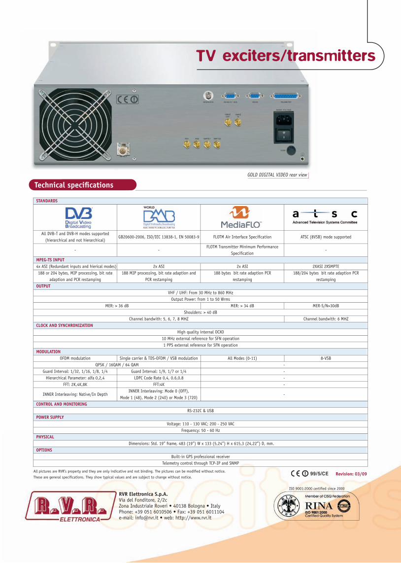
STANDARDS
All DVB-T and DVB-H modes supported
GB20600-2006, ISO/IEC 13838-1, EN 50083-9 FLOTM Air Interface Specifi cation ATSC (8VSB) mode supported (hierarchical and not hierarchical)
-
- FLOTM Transmitter Minimum Performance
- Specifi cation MPEG-TS INPUT 4x ASI (Redundant inputs and hierical modes) 2x ASI 2x ASI 2XASI 2XSMPTE 188 or 204 bytes, MIP processing, bit rate 188 MIP processing, bit rate adaption and 188 bytes bit rate adaption PCR 188/204 bytes bit rate adaption PCR adaption and PCR restamping PCR restamping restamping restamping OUTPUT VHF / UHF: From 30 MHz to 860 MHz Output Power: from 1 to 50 Wrms MER: > 36 dB MER: > 34 dB MER-S/N>30dB Shoulders: > 40 dB Channel bandwith: 5, 6, 7, 8 MHZ Channel bandwith: 6 MHZ CLOCK AND SYNCHRONIZATION High quality internal OCXO 10 MHz external reference for SFN operation 1 PPS external reference for SFN operation MODULATION OFDM modulation Single carrier & TDS-OFDM / VSB modulation All Modes (0-11) 8-VSB QPSK / 16QAM / 64 QAM - Guard Interval: 1/32, 1/16, 1/8, 1/4 Guard Interval: 1/9, 1/7 or 1/4 - Hierarchical Parameter: alfa 0,2,4 LDPC Code Rate 0,4, 0.6,0.8 - FFT: 2K,4K,8K FFT:4K -
INNER Interleaving: Native/In Depth INNER Interleaving: Mode 0 (OFF),
- Mode 1 (48), Mode 2 (240) or Mode 3 (720) CONTROL AND MONITORING RS-232C & USB POWER SUPPLY Voltage: 110 - 130 VAC; 200 - 250 VAC Frequency: 50 - 60 Hz PHYSICAL Dimensions: Std. 19” frame, 483 (19”) W x 133 (5,24”) H x 615,3 (24,22”) D, mm. OPTIONS Built-in GPS professional receiver Telemetry control through TCP-IP and SNMP
GOLD DIGITAL VIDEO rear view
TV exciters/transmitters
RVR Elettronica S.p.A. • Phone +39 051 6010506 • Fax +39 051 6011104 • e-mail: [email protected] • Web: http://www.rvr.it
Features - Caratteristiche
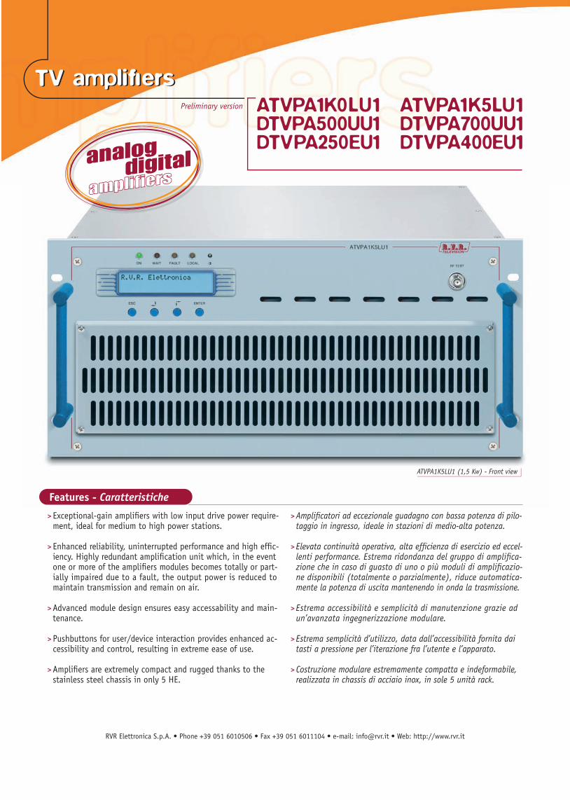
ATVPA1K5LU1 (1,5 Kw) - Front view
TV amplifi ers TV amplifi ers Preliminary version ATVPA1K0LU1 ATVPA1K5LU1
DTVPA500UU1 DTVPA700UU1DTVPA250EU1 DTVPA400EU1
> Exceptional-gain amplifi ers with low input drive power require- ment, ideal for medium to high power stations.
> Enhanced reliability, uninterrupted performance and high effi c- iency. Highly redundant amplifi cation unit which, in the event one or more of the amplifi ers modules becomes totally or part- ially impaired due to a fault, the output power is reduced to maintain transmission and remain on air. > Advanced module design ensures easy accessability and main- tenance. > Pushbuttons for user/device interaction provides enhanced ac- cessibility and control, resulting in extreme ease of use.
> Amplifi ers are extremely compact and rugged thanks to the stainless steel chassis in only 5 HE.
> Amplifi catori ad eccezionale guadagno con bassa potenza di pilo- taggio in ingresso, ideale in stazioni di medio-alta potenza.
> Elevata continuità operativa, alta effi cienza di esercizio ed eccel- lenti performance. Estrema ridondanza del gruppo di amplifi ca- zione che in caso di guasto di uno o più moduli di amplifi cazio- ne disponibili (totalmente o parzialmente), riduce automatica- mente la potenza di uscita mantenendo in onda la trasmissione.
> Estrema accessibilità e semplicità di manutenzione grazie ad un’avanzata ingegnerizzazione modulare. > Estrema semplicità d’utilizzo, data dall’accessibilità fornita dai tasti a pressione per l’iterazione fra l’utente e l’apparato. > Costruzione modulare estremamente compatta e indeformabile, realizzata in chassis di acciaio inox, in sole 5 unità rack.

RVR Elettronica S.p.A. • Phone +39 051 6010506 • Fax +39 051 6011104 • e-mail: [email protected] • Web: http://www.rvr.it
RVR Elettronica S.p.A.Via del Fonditore, 2/2cZona Industriale Roveri • 40138 Bologna • ItalyPhone: +39 051 6010506 • Fax: +39 051 6011104e-mail: [email protected] • web: http://www.rvr.it
ISO 9001:2000 certified since 2000
Technical specifications
All pictures are RVR’s property and they are only indicative and not binding. The pictures can be modified without notice.
These are general specifications. They show typical values and are subject to change without notice.Revision: 03/09
1000Wps 1500Wps Parameters Values Values GENERALS Frequency Range Bd IV & V (470-860 Mhz) Standards All standards Working Temperature 0-45 °C Relative maximum humidity 95% non-condensing Interlock Connector BNC Serial Interface RS 232 / RS485 Input Connector N-type female connector, 50 Ohm Output Connector 7/8” connector Cooling Air forced RF SECTION SPECIFICATIONS ANALOGIC Output Power 1000Wps Analogic 1500Wps Analogic Amplification Mode Common Audio-Video I.M.D. at nominal power better than –60 dBc Output spurious and harmonics < -60 dBc (with output filter) RF SECTION SPECIFICATIONS 8-VSB Output Power 500Wrms 700Wrms RF SECTION SPECIFICATIONS DVB-T/H Output Power 250Wrms 400Wrms METERING Output power Reflected power Power supply meter Temperature Absorbed current Enable status PROTECTIONS VSWR Overdriver Overtemperature Overcurrent MAINS SECTION SPECIFICATIONS Mains Voltage 180/230 Vac (50/60 Hz) ~2100W Analogic (50% APL) ~3500W Analogic (50% APL) Power consumption ~2100W 8-VSB ~3500W 8-VSB ~1300W DVB-T/H ~2200W DVB-T/H Power Factor 0.9 MECHANICAL SPECIFICATIONS Dimensions 5 HE
TV amplifiers
RVR Elettronica S.p.A. • Phone +39 051 6010506 • Fax +39 051 6011104 • e-mail: [email protected] • Web: http://www.rvr.it
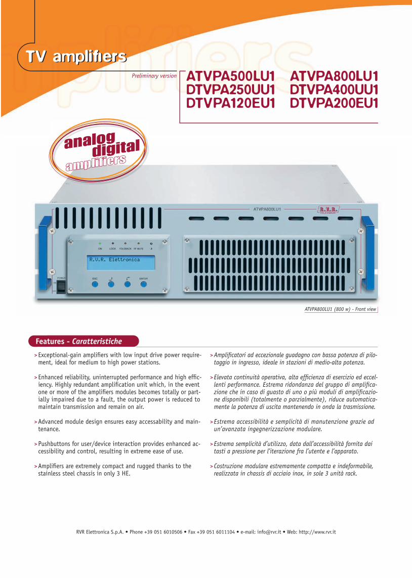
ATVPA800LU1 (800 w) - Front view
Features - Caratteristiche
TV amplifi ers TV amplifi ers Preliminary version ATVPA500LU1 ATVPA800LU1
DTVPA250UU1 DTVPA400UU1DTVPA120EU1 DTVPA200EU1
> Exceptional-gain amplifi ers with low input drive power require- ment, ideal for medium to high power stations.
> Enhanced reliability, uninterrupted performance and high effi c- iency. Highly redundant amplifi cation unit which, in the event one or more of the amplifi ers modules becomes totally or part- ially impaired due to a fault, the output power is reduced to maintain transmission and remain on air. > Advanced module design ensures easy accessability and main- tenance. > Pushbuttons for user/device interaction provides enhanced ac- cessibility and control, resulting in extreme ease of use.
> Amplifi ers are extremely compact and rugged thanks to the stainless steel chassis in only 3 HE.
> Amplifi catori ad eccezionale guadagno con bassa potenza di pilo- taggio in ingresso, ideale in stazioni di medio-alta potenza.
> Elevata continuità operativa, alta effi cienza di esercizio ed eccel- lenti performance. Estrema ridondanza del gruppo di amplifi ca- zione che in caso di guasto di uno o più moduli di amplifi cazio- ne disponibili (totalmente o parzialmente), riduce automatica- mente la potenza di uscita mantenendo in onda la trasmissione.
> Estrema accessibilità e semplicità di manutenzione grazie ad un’avanzata ingegnerizzazione modulare. > Estrema semplicità d’utilizzo, data dall’accessibilità fornita dai tasti a pressione per l’iterazione fra l’utente e l’apparato. > Costruzione modulare estremamente compatta e indeformabile, realizzata in chassis di acciaio inox, in sole 3 unità rack.

RVR Elettronica S.p.A. • Phone +39 051 6010506 • Fax +39 051 6011104 • e-mail: [email protected] • Web: http://www.rvr.it
RVR Elettronica S.p.A.Via del Fonditore, 2/2cZona Industriale Roveri • 40138 Bologna • ItalyPhone: +39 051 6010506 • Fax: +39 051 6011104e-mail: [email protected] • web: http://www.rvr.it
ISO 9001:2000 certified since 2000
Technical specifications
All pictures are RVR’s property and they are only indicative and not binding. The pictures can be modified without notice.
These are general specifications. They show typical values and are subject to change without notice.Revision: 03/09
500Wps 800Wps Parameters Values Values GENERALS Frequency Range Bd IV & V (470-860 Mhz) Standards All standards Working Temperature 0-45 °C Relative maximum humidity 95% non-condensing Interlock Connector BNC Serial Interface RS 232 / RS485 Input Connector N-type female connector, 50 Ohm Output Connector 7/8” connector Cooling Air forced RF SECTION SPECIFICATIONS ANALOGIC Output Power 500Wps Analogic 800Wps Analogic Amplification Mode Common Audio-Video I.M.D. at nominal power better than –60 dBc Output spurious and harmonics < -60 dBc (with output filter) RF SECTION SPECIFICATIONS 8-VSB Output Power 250Wrms 400Wrms RF SECTION SPECIFICATIONS DVB-T/H Output Power 120Wrms 200Wrms METERING Output power Reflected power Power supply meter Temperature Absorbed current Enable status PROTECTIONS VSWR Overdriver Overtemperature Overcurrent MAINS SECTION SPECIFICATIONS Mains Voltage 180/230 Vac (50/60 Hz) ~1100W Analogic (50% APL) ~1900W Analogic (50% APL) Power consumption ~1100W 8-VSB ~1900W 8-VSB ~700W DVB-T/H ~1200W DVB-T/H Power Factor 0.9 MECHANICAL SPECIFICATIONS Dimensions 3 HE
TV amplifiers

RVR Elettronica S.p.A. • Phone +39 051 6010506 • Fax +39 051 6011104 • e-mail: [email protected] • Web: http://www.rvr.it
ATVPA400LU1 (400 w) - Front view
Features - Caratteristiche
TV amplifi ers TV amplifi ers Preliminary version ATVPA250LU1 ATVPA400LU1
DTVPA100UU1 DTVPA200UU1DTVPA050EU1 DTVPA100EU1
> Exceptional-gain amplifi ers with low input drive power require- ment, ideal for medium to high power stations.
> Enhanced reliability, uninterrupted performance and high effi c- iency. Highly redundant amplifi cation unit which, in the event one or more of the amplifi ers modules becomes totally or part- ially impaired due to a fault, the output power is reduced to maintain transmission and remain on air. > Advanced module design ensures easy accessability and main- tenance. > Pushbuttons for user/device interaction provides enhanced ac- cessibility and control, resulting in extreme ease of use.
> Amplifi ers are extremely compact and rugged thanks to the stainless steel chassis in only 3 HE.
> Amplifi catori ad eccezionale guadagno con bassa potenza di pilo- taggio in ingresso, ideale in stazioni di medio-alta potenza.
> Elevata continuità operativa, alta effi cienza di esercizio ed eccel- lenti performance. Estrema ridondanza del gruppo di amplifi ca- zione che in caso di guasto di uno o più moduli di amplifi cazio- ne disponibili (totalmente o parzialmente), riduce automatica- mente la potenza di uscita mantenendo in onda la trasmissione.
> Estrema accessibilità e semplicità di manutenzione grazie ad un’avanzata ingegnerizzazione modulare. > Estrema semplicità d’utilizzo, data dall’accessibilità fornita dai tasti a pressione per l’iterazione fra l’utente e l’apparato. > Costruzione modulare estremamente compatta e indeformabile, realizzata in chassis di acciaio inox, in sole 3 unità rack.
RVR Elettronica S.p.A. • Phone +39 051 6010506 • Fax +39 051 6011104 • e-mail: [email protected] • Web: http://www.rvr.it
RVR Elettronica S.p.A.Via del Fonditore, 2/2cZona Industriale Roveri • 40138 Bologna • ItalyPhone: +39 051 6010506 • Fax: +39 051 6011104e-mail: [email protected] • web: http://www.rvr.it
ISO 9001:2000 certified since 2000
Technical specifications
All pictures are RVR’s property and they are only indicative and not binding. The pictures can be modified without notice.
These are general specifications. They show typical values and are subject to change without notice.Revision: 03/09
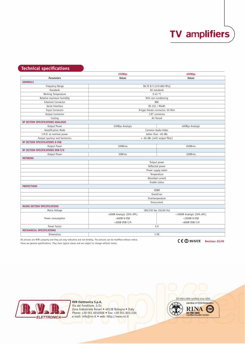
250Wps 400Wps Parameters Values Values GENERALS Frequency Range Bd IV & V (470-860 Mhz) Standards All standards Working Temperature 0-45 °C Relative maximum humidity 95% non-condensing Interlock Connector BNC Serial Interface RS 232 / RS485 Input Connector N-type female connector, 50 Ohm Output Connector 7/8” connector Cooling Air forced RF SECTION SPECIFICATIONS ANALOGIC Output Power 250Wps Analogic 400Wps Analogic Amplification Mode Common Audio-Video I.M.D. at nominal power better than –60 dBc Output spurious and harmonics < -60 dBc (with output filter) RF SECTION SPECIFICATIONS 8-VSB Output Power 100Wrms 200Wrms RF SECTION SPECIFICATIONS DVB-T/H Output Power 50Wrms 100Wrms METERING Output power Reflected power Power supply meter Temperature Absorbed current Enable status PROTECTIONS VSWR Overdriver Overtemperature Overcurrent MAINS SECTION SPECIFICATIONS Mains Voltage 180/230 Vac (50/60 Hz) ~600W Analogic (50% APL) ~1000W Analogic (50% APL) Power consumption ~600W 8-VSB ~1000W 8-VSB ~300W DVB-T/H ~600W DVB-T/H Power Factor 0.9 MECHANICAL SPECIFICATIONS Dimensions 3 HE
TV amplifiers

RVR Elettronica S.p.A. • Phone +39 051 6010506 • Fax +39 051 6011104 • e-mail: [email protected] • Web: http://www.rvr.it
Features - Caratteristiche
> Exceptional-gain amplifi ers, ideal for medium to high power stations.
> Enhanced reliability, uninterrupted performance and high effi ciency. > Advanced module design ensures easy accessability and main- tenance. > Pushbuttons for user/device interaction provides enhanced accessibility and control, resulting in extreme ease of use. > Amplifiers are extremely compact and rugged in only 5 HE.
> Estrema potenza di amplifi cazione, impiego ideale in stazioni di medio-alta potenza.
> Elevata continuità operativa, alta effi cienza di esercizio ed eccel- lenti performance. > Estrema accessibilità e semplicità di manutenzione grazie ad un’avanzata ingegnerizzazione modulare. > Estrema semplicità d’utilizzo, data dall’accessibilità fornita dai tasti a pressione per l’iterazione fra l’utente e l’apparato. > Costruzione modulare estremamente compatta e indeformabile, in sole 5 unità rack.
SAU-SAV31 front view
TV amplifi ers TV amplifi ers Preliminary version SAU31
SAV31
Technical specifications
All pictures are RVR’s property and they are only indicative and not binding. The pictures can be modified without notice.
These are general specifications. They show typical values and are subject to change without notice.Revision: 03/09
Parameters Values GENERALS
Frequency Range SAV-31 - Bd III (170-230 Mhz)
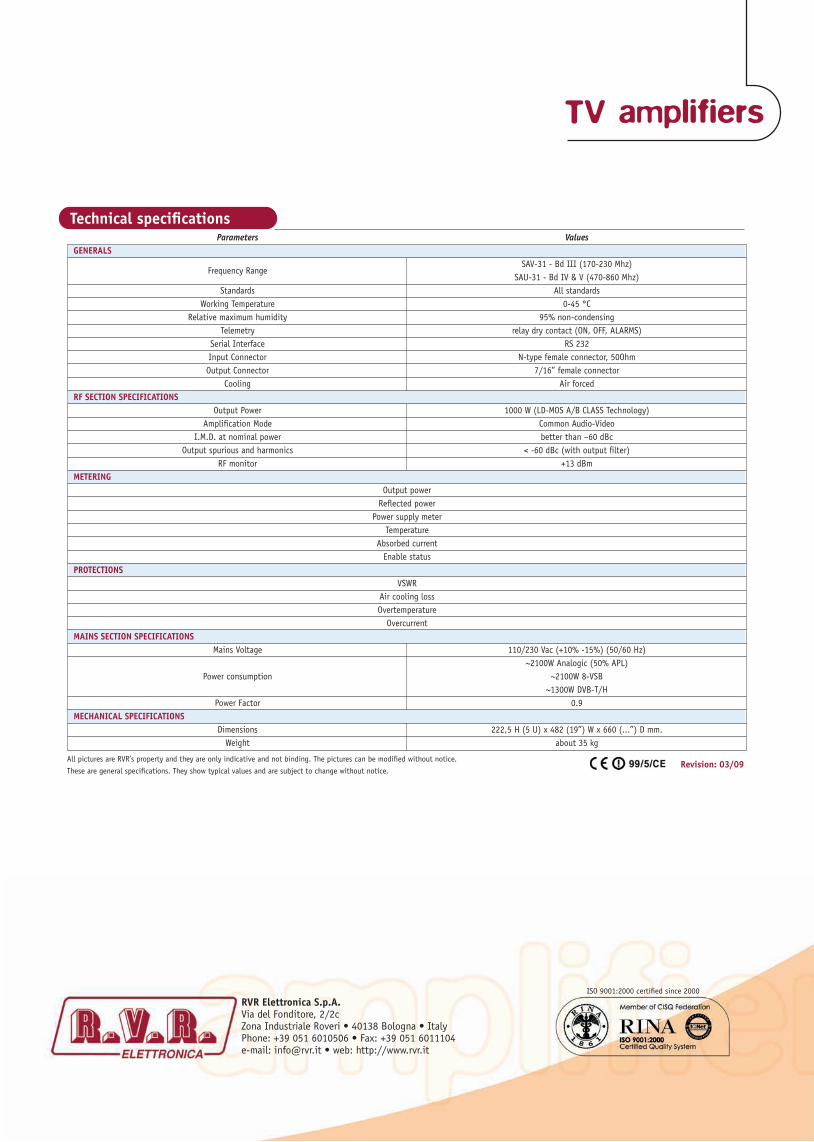
SAU-31 - Bd IV & V (470-860 Mhz) Standards All standards Working Temperature 0-45 °C Relative maximum humidity 95% non-condensing Telemetry relay dry contact (ON, OFF, ALARMS) Serial Interface RS 232 Input Connector N-type female connector, 50Ohm Output Connector 7/16” female connector Cooling Air forced RF SECTION SPECIFICATIONS Output Power 1000 W (LD-MOS A/B CLASS Technology) Amplification Mode Common Audio-Video I.M.D. at nominal power better than –60 dBc Output spurious and harmonics < -60 dBc (with output filter) RF monitor +13 dBm METERING Output power Reflected power Power supply meter Temperature Absorbed current Enable status PROTECTIONS VSWR Air cooling loss Overtemperature Overcurrent MAINS SECTION SPECIFICATIONS Mains Voltage 110/230 Vac (+10% -15%) (50/60 Hz) ~2100W Analogic (50% APL) Power consumption ~2100W 8-VSB ~1300W DVB-T/H Power Factor 0.9 MECHANICAL SPECIFICATIONS Dimensions 222,5 H (5 U) x 482 (19”) W x 660 (...”) D mm. Weight about 35 kg
TV amplifiers
RVR Elettronica S.p.A.Via del Fonditore, 2/2cZona Industriale Roveri • 40138 Bologna • ItalyPhone: +39 051 6010506 • Fax: +39 051 6011104e-mail: [email protected] • web: http://www.rvr.it
ISO 9001:2000 certified since 2000

TV transmitters TV transmitters
Features
STUM-STVM front view
R.V.R. Television family STU/STV
-
-
EXCITERSR.V.R. Television STU 05/STV 05
-
La famiglia di trasmettitori televisivi R.V.R. STU/STV (per UHF/VHF) è costituita da trasmettitori di media e alta potenza LD-MOS per UHF (frequenze ultra-elevate), e MOSFET per VHF (frequen-ze molto elevate), per la trasmissione di segnali TV analogici in conformità a tutte le norme. L’amplificazione è comune per audio e video, e ciò fa sì che gli amplificatori siano pronti per essere utilizzati con segnali TV digitali DVB-T semplicemente sostituendo il modulatore analogico con il modulatore COFDM per DVB-T. I tra-smettitori sono realizzati nel rispetto delle norme per la sicurezza del personale (conformità alla norma IEC 215).
ECCITATORIGli eccitatori televisivi R.V.R. STU 05/STV 05 (UHF/VHF) sono stati progettati per rispondere alle esigenze dell’amplificazione combinata degli amplificatori allo stato solido che utilizzano LD-MOS/MOSFET. Le dimensioni estremamente compatte della struttura portante che ospita i moduli dell’eccitatore (3U), anche nella versione stereo IRT, consentono di inserire anche il Dual Drive opzionale nella stes-sa unità rack. Inoltre l’oscillatore locale è del tipo sintetizzato, con
AMPLIFIERSamplifiers -
-
FILTERSfilters -
Caratteristiche
la possibilità di OFFSET a intervalli di 1Hz da -32 KHz a +32 KHz. La stabilità dell’oscillatore locale è di ± 150 Hz su sei mesi, ed è inoltre disponibile un ingresso di riferimento esterno a 5 MHz per ottenere una stabilità di ± 1 Hz, necessaria per garantire la preci-sione dell’offset. Tutte le regolazioni ordinarie possono essere facilmente effettuate dal pannello frontale dell’eccitatore stesso.
AMPLIFICATORIL’elemento basilare degli amplificatori di potenza comprende una struttura portante a 5 unità rack. E’ possibile inserire in questa struttura portante 2 moduli a radio frequenza da 300W di alimen-tazione (per il 500W, STU / STV 25) o 4 moduli RF da 300W di ali-mentazione (per il 1000W, STU / STV 31). La ventilazione è garan-tita da due ventilatori ad alto rendimento e con alto MTBF (Tempo Medio Fra i Guasti). L’alimentazione dei moduli a radio frequenza finali è stata migliorata per mezzo di alimentazioni di commutazio-ne gestite dalla rete, una per ogni modulo RF, per ottenere la mas-sima ridondanza, mentre l’RF pilota viene alimentato dalle stesse alimentazioni in parallelo (OR). Questa soluzione permette una
“degradazione morbida” ovvero la riduzione di potenza in uscita in caso di malfunzionamento di un mo-dulo RF o di un’alimenta-zione. Il dissipatore di calore è stato progettato per raggiungere livelli di efficienza molto elevati in modo tale da consentire agli amplificatori di operare nelle condizioni atmosferiche più avverse. I trasmettitori ad alta potenza vengono sviluppati tramite la com-binazione di 2 amplificatori da 1000W per l’alimentazione da 2KW (STU/STV 32), con un ibrido a 3dB, e 5 amplificatori da 1000W per l’alimentazione da 5 KW (STU/STV 35) effettuata da combinatori di potenza a 5 vie combinati a loro volta.
FILTRII filtri RF di uscita sono del tipo PASSA BANDA per l’eliminazione di prodotti di intermodulazione all’esterno dei canali e per garantire che il trasmettitore sia conforme alle norme CCIR.
TV transmitters

RVR Elettronica S.p.A.Via del Fonditore, 2/2c
TV transmitters
MODEL OUTPUT POWER CONSUMPTION POWER CONSUMPTION WEIGHT DIMENSIONS
UHF VHF POWER BLACK LEVEL GREY LEVEL W-D-H (mm)
STU 25 STV 25 500 W 1200 W 1000 W Approx. 160Kg 590-1200-1300
STU 31 STV 31 1.000 W 2700 W 2100 W Approx. 165Kg 590-1200-1300
STU 32 STV 32 2.000 W 5600 W 4300 W Approx. 200Kg 590-1200-1300
STU 33 STV 33 3.000 W 7800 W 6200 W Approx. 380Kg 590-1200-1920
STU 34 STV 34 4.000 W 9900 W 8300 W Approx. 420Kg 590-1200-1920
STU 35 STV 35 5.000 W 12500 W 10000 W Approx. 460Kg 590-1200-1920
MODEL OUTPUT POWER CONSUMPTION POWER CONSUMPTION WEIGHT DIMENSIONS
UHF VHF POWER BLACK LEVEL GREY LEVEL W-D-H (mm)
STU 25 STV 25 500 W 1200 W 1000 W Approx. 160Kg 590-1200-1300
STU 31 STV 31 1.000 W 2700 W 2100 W Approx. 165Kg 590-1200-1300
STU 32 STV 32 2.000 W 5600 W 4300 W Approx. 200Kg 590-1200-1300
STU 33 STV 33 3.000 W 7800 W 6200 W Approx. 380Kg 590-1200-1920
STU 34 STV 34 4.000 W 9900 W 8300 W Approx. 420Kg 590-1200-1920
STU 35 STV 35 5.000 W 12500 W 10000 W Approx. 460Kg 590-1200-1920
Table 1
Technical specifi cations Parameters Values GENERALS
Altitude
RF SECTION SPECIFICATIONS
Standard All standards Intermodulation
TRANSMISSION CHARACTERISTICS
Intercarrier noise
Parameters Values VISION
Return loss
SOUND
METERING
PROTECTION CIRCUIT Over current
VSWR REMOTE CONTROL Parallel on, off, alarms
Revision: 03/09