tutorial auto code generation for f2833x … code generation for f2833x target 2 psim’s simcoder...
TRANSCRIPT
1
TUTORIAL
Auto Code Generation for F2833X Target
OCTOBER 2016
Auto Code Generation for F2833X Target
2
PSIM’s SimCoder Module, combined with F2833x Hardware Target, can generate ready‐to‐run code for hardware based on TI F2833x series floating‐point DSP.
This tutorial describes, in step by step, how to generate code in PSIM, compile and upload the code in Code Composer Studio (CCS), and run it on the DSP.
To illustrate the process, we use the circuit “TI 1‐ch DC/DC buck.psimsch’ as an example. This example is located in the sub‐folder “examples\SimCoder\F2833x Target\TI 1‐Ch DC‐DC” in the PSIM directory.
To keep the original example unchanged, we will copy the whole folder to “c:\ TI 1‐Ch DC‐DC”, and use this folder as the working folder in this tutorial.
1. PSIM Setup for Code Generation
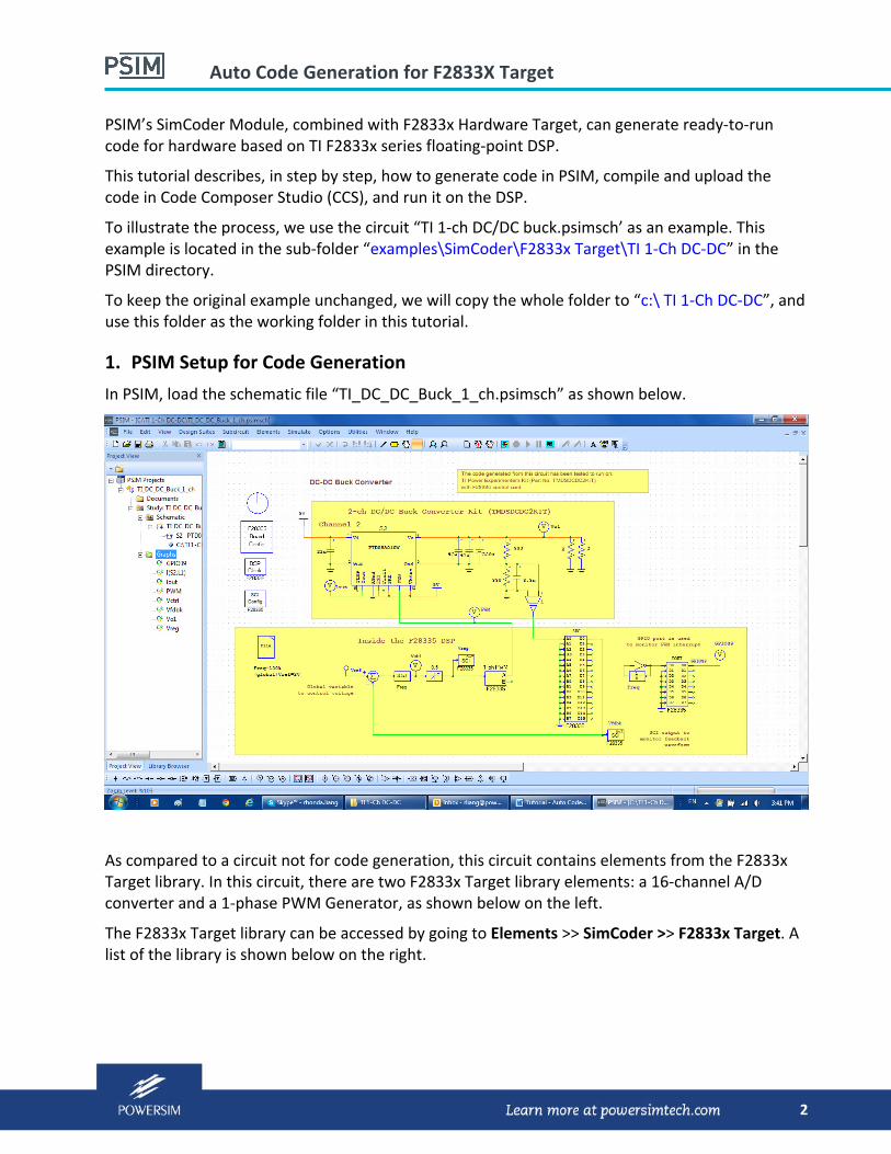
In PSIM, load the schematic file “TI_DC_DC_Buck_1_ch.psimsch” as shown below.
As compared to a circuit not for code generation, this circuit contains elements from the F2833x Target library. In this circuit, there are two F2833x Target library elements: a 16‐channel A/D converter and a 1‐phase PWM Generator, as shown below on the left.
The F2833x Target library can be accessed by going to Elements >> SimCoder >> F2833x Target. A list of the library is shown below on the right.

Auto Code Generation for F2833X Target
3
Like any other circuits, this circuit can be simulated by selecting Simulate >> Run Simulation.
Simulation Control Parameters
Before performing the code generation, first define the project configuration for Code Composer Studio. Double click on the Simulation Control block (the clock image). The Hardware Target should be set to F2833x. Click on the drop‐down menu to choose one of the four project settings. In this case, we will choose RAM Debug, as shown below.
With the RAM Debug setting, it is easy to debug the program and there is no need to write the program to the flash memory.
F28335 Target elements used in the circuit
F2833x Target library list:

Auto Code Generation for F2833X Target
4
Generating Code
To generate code, select Simulate >> Generate Code. The generated code will be displayed in a separate window, as shown below.
PSIM not only generates the C code, but also generates all the necessary project files for four configurations: RAM Debug, RAM Release, Flash Release, and Flash RAM Release. The project file and all dependent files are stored in a sub‐folder called “c:\TI 1‐Ch DC‐DC\ TI_DC_DC_Buck_1_ch (C code)”.
2. CCS Setup
The PSIM generated project is for CCS v3.3. If you are using CCS v3.3, the project can be opened directly; If using CCS 4 or higher, you need to use CCS’s Import Legacy v3.3 Project function. We use CCS v5.5 to show the way to load and debug the program in this document for the example.
Import Project into CCS
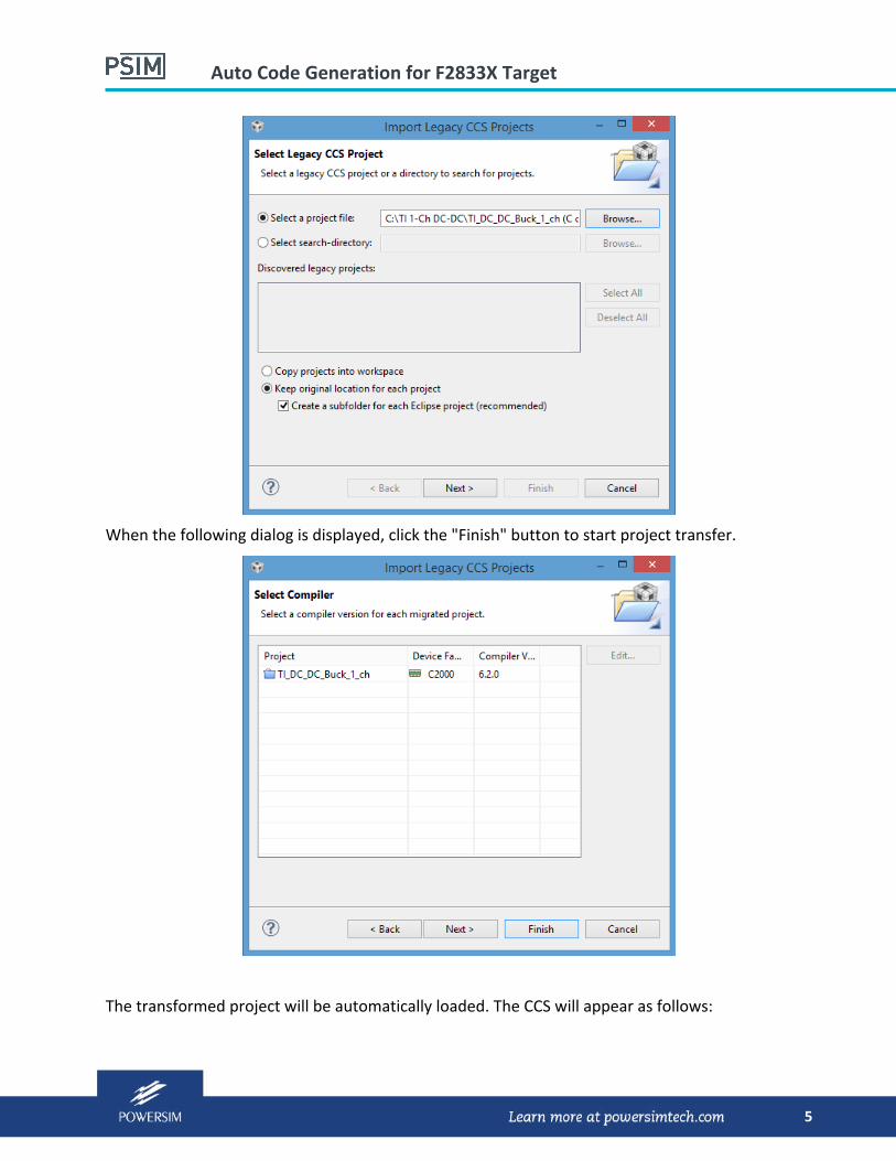
Launch CCS v5.5, if this is the first time you load the project, you need to transfer CCS v3.3 project to CCS v5.5 project by go to Project >> Import Legacy CCSv3.3 Project. The following dialog pops up. click on "Browse..." button to choose " C:\TI 1‐Ch DC‐DC\TI_DC_DC_Buck_1_ch (C code)\TI_DC_DC_Buck_1_ch.pjt" then click "Next" button.
Auto Code Generation for F2833X Target
5
When the following dialog is displayed, click the "Finish" button to start project transfer.
The transformed project will be automatically loaded. The CCS will appear as follows:

Auto Code Generation for F2833X Target
6
Note that the project configuration is set to RAM Debug. With this setting, all program and data will be loaded to the RAM memory.
Compiling Code
To compile the project, right mouse click on the project name "TI_DC_DC_Buck_1_ch" in the pane of Project Explorer, then click on "Build Project" in the popped up menu. Or click on the project name in the pane of Project Explorer to select it as the current project (the project name changes to bold) then select Project >> Build to build the project or Project >> Rebuild All to rebuild the whole project). After the compiling is completed, CCS will display the following:

Auto Code Generation for F2833X Target
7
The warning message can be ignored. This warning message is displayed when program is not saved in the flash memory.
Setting Target Configuration
Before loading a program to the target, we need to create a target configuration for the target board. In this example, a TI TMS320F28335 controlCARD is used. Select View ‐> Target Configurations. Right mouse click on "User Defined", and select "New Target Configuration" in the window, as shown below.
Change the file name as you want (in this example, it is called "F2833x"), and click on the “Finish” button. The file extension will be "ccxml".

Auto Code Generation for F2833X Target
8
In the "Connection" combo box, choose the emulator you will use (for example, "Spectrum Digital C2000 XDS510LC Emulator"), then check "TMS320F28335" in the list box of "Board of Device". Click the "Save" button to save the configuration.
Back to the "Target Configurations" dialog, right mouse click on "F2833x.ccxml" configuration, move mouse to "Link File to Project" in the popped up menu, all projects will be displayed in the sub‐menu. Select "TI_DC_DC_Buck_1_ch" project to add "F2833x.ccxml" to the project. The Project Explorer panel is displayed on the right.
3. Target Hardware Setup
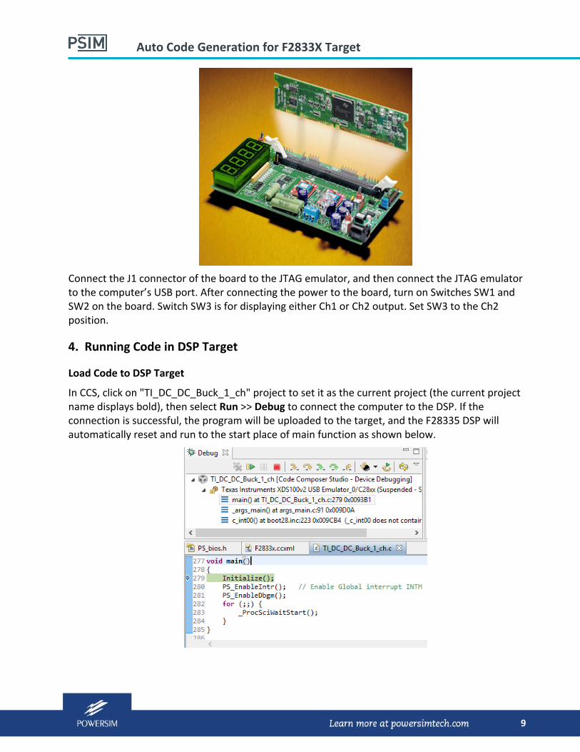
Insert TI’s TMS320F28335 controlCARD into TI’s 2‐Channel DC/DC Buck Converter Kit (TMDSDCDC2KIT), as shown below.
Auto Code Generation for F2833X Target
9
Connect the J1 connector of the board to the JTAG emulator, and then connect the JTAG emulator to the computer’s USB port. After connecting the power to the board, turn on Switches SW1 and SW2 on the board. Switch SW3 is for displaying either Ch1 or Ch2 output. Set SW3 to the Ch2 position.
4. Running Code in DSP Target
Load Code to DSP Target
In CCS, click on "TI_DC_DC_Buck_1_ch" project to set it as the current project (the current project name displays bold), then select Run >> Debug to connect the computer to the DSP. If the connection is successful, the program will be uploaded to the target, and the F28335 DSP will automatically reset and run to the start place of main function as shown below.
Auto Code Generation for F2833X Target
10
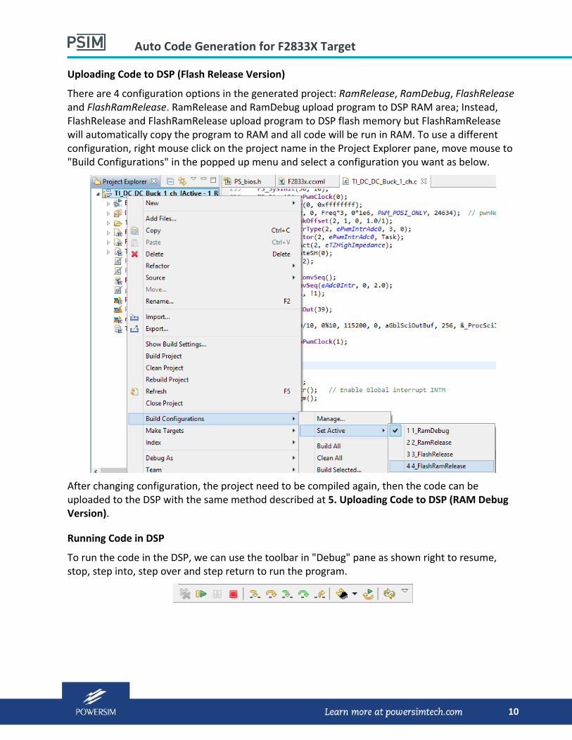
Uploading Code to DSP (Flash Release Version)
There are 4 configuration options in the generated project: RamRelease, RamDebug, FlashRelease and FlashRamRelease. RamRelease and RamDebug upload program to DSP RAM area; Instead, FlashRelease and FlashRamRelease upload program to DSP flash memory but FlashRamRelease will automatically copy the program to RAM and all code will be run in RAM. To use a different configuration, right mouse click on the project name in the Project Explorer pane, move mouse to "Build Configurations" in the popped up menu and select a configuration you want as below.
After changing configuration, the project need to be compiled again, then the code can be uploaded to the DSP with the same method described at 5. Uploading Code to DSP (RAM Debug Version).
Running Code in DSP
To run the code in the DSP, we can use the toolbar in "Debug" pane as shown right to resume, stop, step into, step over and step return to run the program.
Auto Code Generation for F2833X Target
11
Monitoring Waveforms with PSIM’s DSP Oscilloscope
At the end of Section 4, the code is running in the targeted DSP to generate a converter output of 3.3V (+/‐0.05V). Now, one may use PSIM’s DSP Oscilloscope feature to monitor the variables inside the DSP and to control the converter output voltage.
Connect the SCI port of the hardware target to the computer.
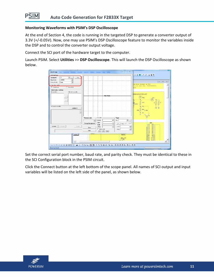
Launch PSIM. Select Utilities >> DSP Oscilloscope. This will launch the DSP Oscilloscope as shown below.
Set the correct serial port number, baud rate, and parity check. They must be identical to these in the SCI Configuration block in the PSIM circuit.
Click the Connect button at the left bottom of the scope panel. All names of SCI output and input variables will be listed on the left side of the panel, as shown below.

Auto Code Generation for F2833X Target
12
The two variables available for monitoring are Vfdbk and Ref_out. Select the variables to display on the scope screen.
To change the DC‐DC converter output voltage, modify the value Vref to 2 and click the Update button. The LED display of the converter board will change to the new value. The figure below shows the waveforms with the new value of Vref.

Auto Code Generation for F2833X Target
13
6. Code Composer Studio References
For further information about the Texas Instrument’s Code Composer Studio, please refer to the documents in the links below.
CCSv5 Getting Started GuideCCSv5 Getting Started Guide
http://processors.wiki.ti.com/index.php/CCSv5_Getting_Started_Guide