tutorial 3: gearcalc (pdf)
TRANSCRIPT

1 / 12 19. Januar 2007 GEARCALC-tut-003-E-GearCalc.doc
KISSsoft U.S.A., LLC - Telephone: (815) 363-8823 3719 N. Spring Grove Road - Fax: (815) 363-8832 Johnsburg, Illinois 60050 - [email protected] www.GEARCALC.com
GEARCALC Tutorial 003: GEARCALC __________________________________________________________________________________________ Keywords: AGMA 2001, GearCalc For release: File: GEARCALC-tut-003-E-GearCalc.doc Created / modified: 15.12.2006, M.Fish / 16.12.06 U. Kissling / 18.01.2007, A.Halter Download: __________________________________________________________________________________________
Starting GEARCALC
Starting GEARCALC After installation, an icon can be found in the program list accessed using ‘Start’ in the bottom left hand corner of the screen. Alternatively click on the GEARCALC icon in the Windows Browser under “C:\Programs\GEARCALC\bin\GEARCALC.exe”. The following window will appear:
GEA
RCA
LC T
utor
ial 0
03: G
EARC
ALC

2 / 12
Using GEARCALC
The GEARCALC calculation is carried out on several pages (windows). The macro geometry is defined on the first tab side of the program which is shown by default:
These can be indexed through by clicking on the ‘Next’ button as indicated by the red marker. Data on previous pages can be edited by returning using the ‘Previous’ button.

3 / 12
Enter Data
Task description A power take off to a 10HP hydraulic pump for a gas turbine accessory for an off-road vehicle is required. The pinion speed is 1260rpm and the gear ratio is exactly 5. The center distance is to be exactly 6.5 inches. The required life is only 132 hours. Minimum weight is desired, so the gear set will be designed for maximum load capacity.
Enter Data
Calculation Geometry [Page 1] For the application description, some general application characteristics are: Type : Spur Helix Angle (ψ) : 0.0° Normal Pressure Angle (ϕn) : 20.0° These are entered in the fields in the first page by default. Other criteria must be defined. From the task outline: Ratio mG(u) : 5.0
The gears are to be carburized and ground for maximum load capacity. The process permits profile modification. Select smooth running from the profile modification options:
The reliability required will remain at the default of 99%. Safety Factors: SF = 1. SH= 1.
4 / 12
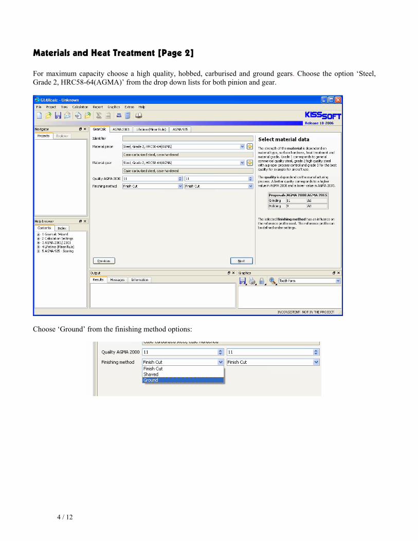
Materials and Heat Treatment [Page 2] For maximum capacity choose a high quality, hobbed, carburised and ground gears. Choose the option ‘Steel, Grade 2, HRC58-64(AGMA)’ from the drop down lists for both pinion and gear.
Choose ‘Ground’ from the finishing method options:

5 / 12
Operating Conditions [Page 3] The power (P = 10hp), the pinion speed (ω=1260rpm) and life time (L=132h) as defined by the task specification can be entered directly in the cells provided on this tab page.
Factors defining the operation are also defined here. The factor for load distribution, Km(KH), can be calculated by the program. In this case though, since the housing is aluminium and uneven heat distribution is expected the factor is estimated at 1.4. The value can be entered directly in the cell after ticking the box at the side of the input field.
The dynamic factor KV will be determined by the program. Further, the gear set has one contact mesh, one way rotation and the pinion is driving with no idlers or planet gears. In this case, the remaining settings remain as they appear by default:

6 / 12
Presize [Page 4] When opening the ‘Presize’ window (Page 4) the values for the presize case 1 (center distance C, pinion pitch diameter d1, face width F and normal diametral pitch Pnd are proposed by the algorithm) will be presented automatically:
In this example the centre distance is fixed to 6.5 inches. This value can be entered directly be ticking the box at the side of the entry field.
Then the program has do be asked to redo the presizing by clicking on button. Now presize case 2 (center distance C is given, face width F and normal diametral pitch Pnd are proposed by the algorithm) is presented:
7 / 12
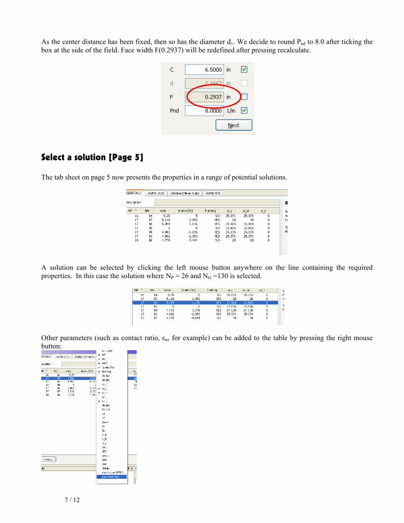
As the center distance has been fixed, then so has the diameter d1. We decide to round Pnd to 8.0 after ticking the box at the side of the field. Face width F(0.2937) will be redefined after pressing recalculate.
Select a solution [Page 5] The tab sheet on page 5 now presents the properties in a range of potential solutions.
A solution can be selected by clicking the left mouse button anywhere on the line containing the required properties. In this case the solution where NP = 26 and NG =130 is selected.
Other parameters (such as contact ratio, εα, for example) can be added to the table by pressing the right mouse button:

8 / 12
We add “maxPower” to the list. As every solution (with different tooth numbers) will have a slightly different transmittable power rating, this information may be helpful.
Addendum Modification [Page 6] For this application, the bending strength should be optimised if possible. Choose X1 = 0.53.
The required input is now complete. On pressing ‘Finish’ the following message will appear :
Selecting ‘Yes’ will generate a text report in the work space ready from printing. A copy of the report has been included as an Annex to this tutorial.

9 / 12
On closing the report and returning to the calculation using the icon , then the complete set of data will be transferred to the AGMA 2001 window. See the tutorial 001 (AGMA 2001) for further information.

10 / 12
ANNEX
GEARCALC - Release 12-2006 GEARCALC evaluation version File Name : Tutorial No 1 Example Changed by : uk on: 12/16/06 at: 8:58 pm Results for GearCalc Sizing INPUT DATA SUMMARY GEAR GEOMETRY DATA Gear mesh type = External Helix type = Spur gear Normal pressure angle PHI(n) = 20.0000 Standard helix angle PSI(s) = 0.0000 Required gear ratio m(G) = 5.0000 Profile modification = for uniform mesh NOTE: All dims in in, all angles in degrees, all stresses in lb/in². MATERIALS/HEAT-TREATMENT DATA Pinion Gear Material (Pinion) = Steel, Grade 2, HRC58-64(AGMA) AGMA 2001-C95; AGMA 2101-C95 Material (Gear) = Steel, Grade 2, HRC58-64(AGMA) AGMA 2001-C95; AGMA 2101-C95 Material type = Case-carburized stee Case-carburized stee Heat-treatment = case-hardened case-hardened Modulus of elasticity (lb/in²) EP,EG = 30000000 30000000 Poisson's ratio MU(P),MU(G) = 0.3000 0.3000 Surface hardness HRC 60 HRC 60 Allowable contact stress SAC(P), SAC(G) = 225000 225000 Allowable bending stress SAT(P), SAT(G) = 65000 65000 Finishing method (0=Finish, 1=Shaved 2=Ground) = 2 2 LOAD DATA Transmitted power (HP) P = 10.0000 Pinion speed (rpm) n(P) = 1260.0000 Required life (HRS) L = 132 Overload (or application) factor Ko = 1.0000 Dynamic factor Kv = 1.1152 Load distribution factor Km = 1.4000 Pitting safety factor SH = 1.0000 Bending fatigue safety factor SF = 1.0000 Reliability R = 99 % Driving: = PINION Number of contacts per revolution = 1 1 Reversed bending (0=No; 1=Yes) = 0 0 Spur gear loading type = TIP Stress cycle factors, Curve chosen, Figs. 17 & 18 = Lower (for critical applications) *** DESIGN OPTIONS *** Operating center distance: By Input Operating center distance (in) C = 6.5000 LAST PRESIZE SOLUTION (Case 7): INPUT OUTPUT

11 / 12
Pinion operating pitch dia. (in) d = 2.1667 2.1667 Face width (in) F = 0.0000 0.2937 Normal diametral pitch (1/in) Pnd = 8.0000 8.0000 Durability & Bending criteria are not balanced Selection of Variants: NP NG ratio ?ratio (%) hunting ?_r ?_nr ?_r 16 84 5.25 5 NO 25.371 25.371 0 17 87 5.118 2.353 YES 20 20 0 17 86 5.059 1.176 YES 21.463 21.463 0 17 85 5 0 NO 22.836 22.836 0 17 84 4.941 -1.176 YES 24.135 24.135 0 17 83 4.882 -2.353 YES 25.371 25.371 0 18 86 4.778 -4.444 NO 20 20 0 (z1 is NP, z2 is NG) Tooth number combination chosen NP,NG = 17 86 Addendum modification coeff. selected x1 = 0.5300 ADDENDUM MODIFICATION COEFF. OPTIONS Options for profile shift coefficient: x1 x2 - For general purpose 0.3529 0.1648 - For balanced specific sliding 0.4669 0.0509 - For best strength against bending 0.4450 0.0727 - For best strength against scoring 0.3000 0.2177 - Limit for undercut 0.1754 -3.8603 - Limit for minimal topland 0.8146 2.5580 - Choosen profile shift coefficient 0.5300 -0.0123 GEOMETRY SUMMARY Pinion Gear Tooth number NP,NG = 17 86 Net face width F1,F2 = 0.2937 0.2937 Outside diameter do,Do = 2.5053 10.9947 Normal diametral pitch Pnd = 8.0000 Normal pressure angle PHI(n) = 20.0000 Standard helix angle PSI(s) = 0.0000 Operating center distance C = 6.5000 ***Gear geometry data for Pnd = 1.0*** Profile shift coefficient X1,X2 = 0.53000 -0.01227 Thinning for backlash del.sn1, del.sn2 = 0.02400 0.02400 Stock allow. per side for finishing Us1,Us2 = 0.04920 0.04920 ***Tool geometry data for Pnd = 1.0*** Tool normal tooth thickness tce1,tce2 = 1.5708 1.5708 Tool addendum (Precutting) hao1,hao2 = 1.4000 1.4000 Tool addendum (Finish) hao1,hao2 = 1.2648 1.2648 Tool tip radius rTe1,rTe2 = 0.3500 0.3500 Tool protuberance DELTA(o1),DELTA(o2) = 0.0502 0.0502 Tool protuberance ANGLE(1),ANGLE(2) = 10.0000 10.0000 REFERENCE DATA Pinion Gear Operating transverse pressure angle PHI(t) = 21.4625 Operating normal pressure angle PHI(n) = 21.4625 Operating helix angle PSI = 0.0000 Actual gear ratio mG = 5.0588 Transverse (profile) contact ratio mp = 1.4861 Axial (face) contact ratio mF = 0.0000 Face width/Pinion dia. ratio (F/d) m(a) = 0.1369 Solid rotor volume (IN^3) V = 1.1401 26.4691 Tooth number combo (Hunting/Non-Hunting) = Hunting Pitch line velocity (FPM) vt = 707.8 Transmitted tangential load (LB.) Wt = 470.8

12 / 12
Contact load factor for pitting resist. K = 885.9 Unit load factor for bending strength U(L) = 12696.9 Hardness ratio factor C(H) = 1.0000 1.0000 Temperature factor K(T) = 1.0000 1.0000 Reliability factor K(R) = 1.0000 Stress cycle factor (Contact) Z(N) = 1.0001*a* 1.0951*a* Stress cycle factor (Root) Y(N) = 1.0001*a* 1.0930*a* Allow. contact stress No. (lb/in²) Sac = 225023 246407 Allow. bending stress No. (lb/in²) Sat = 65006 71042