turf runner model str - scagscag.com/opmanuals/str/97stropman/97stropmancomplete.pdf ·...
TRANSCRIPT

������������� �����������������
��������������
����������
TURF RUNNERMODEL STR

������������������� ������� �����������������������������������
����������������������� ������� ����������������� ����� ������������������������������������ ��������� ������������� ����������������������������������������������������������� ������� ����� ����������������������������� ������������������������������ ���������������������������������������������������� �������������������������������������� ��������������������������������������������� ���� ������������������������!�
REMEMBER - YOUR MOWER IS ONLY AS SAFE AS THE OPERATOR!Hazard control and accident prevention are dependent upon the awareness,concern, prudence, and proper training of the personnel involved in theoperation, transport, maintenance, and storage of the equipment.
WARNING
"��������� ����������������������� ���������������������������������#
������������� �� �� ��!� "#$%� � &'� �(�(���)��(�(****������������� �� �� ��!� "#$%� � &'� �()(���)��()(****
$������������������������������������������������������������������������������������ ��

FROM SERIAL NUMBER 60001 TO 69999
OPERATOR'S MANUAL
PART 03028
TURF RUNNERMODEL STR

FAILURE TO FOLLOW SAFE OPERATING PRACTICES MAY RESULT IN SERIOUS INJURY.
* Keep all shields in place, especially the grass discharge chute.* Before performing any maintenance or service, stop the machine and remove the spark plug wire and ignition key.* If a mechanism becomes clogged, stop the engine before cleaning.* Keep hands, feet and clothing away from power-driven parts.* Read this manual completely as well as other manuals that came with your mower.* Keep others off the tractor (only one person at a time).
REMEMBER - YOUR MOWER IS ONLY AS SAFE AS THE OPERATOR!Hazard control and accident prevention are dependent upon the awareness,concern, prudence, and proper training of the personnel involved in theoperation, transport, maintenance, and storage of the equipment.
WARNING
This manual covers the operating instructions and illustrated parts list for:
STR-20CH with a serial number of 21660001-21669999STR-22CH with a serial number of 21760001-21769999
Always use the entire serial number listed on the serial numbertag when referring to this product.
I
TABLE OF CONTENTS
SUBJECT PAGE
Section 1 - General Information1.1 Introduction ............................................................................................................................ 11.2 Directional Reference ............................................................................................................. 11.3 Servicing the Engine and Drive Train Components ............................................................... 1
Section 2 - Safety Information2.1 Introduction ............................................................................................................................ 22.2 Signal Words .......................................................................................................................... 22.3 Before Operation Considerations ........................................................................................... 22.4 Operation Considerations ....................................................................................................... 32.5 Maintenance Considerations ..................................................................................................42.6 Safety and Instructional Decals .............................................................................................5
Section 3 - Specifications..................................................................................................... ..6-7
Section 4 - Operating Instructions4.1 Controls and Instrument Identification ................................................................................... 84.2 Safety Interlock System ....................................................................................................... 104.3 Initial Run-In Procedures ..................................................................................................... 104.4 Starting the Engine ............................................................................................................... 104.5 Ground Travel and Steering ................................................................................................. 104.6 Engaging the Deck Drive .....................................................................................................124.7 Hillside Operation ................................................................................................................ 134-8 Parking the Mower ............................................................................................................... 134.9 After Operation .................................................................................................................... 134.10 Hopper/Side Discharge Operation ....................................................................................... 144.11 Removing Clogged Material ................................................................................................ 154.12 Moving Mower with Engine Stopped .................................................................................. 164.13 Recommendations for Mowing ............................................................................................ 164.14 Adjusting Cutting Height ..................................................................................................... 174.15 Tilting the Cutter Deck......................................................................................................... 174.16 Removing the Cutter Deck ...................................................................................................17
Section 5 - Troubleshooting Cutting Conditions............................................................. 20-22

II
TABLE OF CONTENTS (CONT'D)
SUBJECT PAGE
Section 6 - Adjustments6.1 Parking Brake Adjustment ................................................................................................... 236.2 Travel Adjustments .............................................................................................................. 246.3 Throttle Control and Choke Adjustments............................................................................. 286.4 Engine Belt Adjustment ....................................................................................................... 286.5 Blower Drive Belt Adjustment ............................................................................................. 286.6 Transmission Drive Belt Adjustment ................................................................................... 286.7 Belt Alignment..................................................................................................................... 28
Section 7 - Maintenance7.1 Maintenance Chart ............................................................................................................... 297.2 Lubrication........................................................................................................................... 307.3 Hydraulic System ................................................................................................................. 327.4 Engine Oil ............................................................................................................................ 337.5 Engine Fuel System..........................................................................................................347.6 Engine Air Cleaner ............................................................................................................... 347.7 Battery ................................................................................................................................. 357.8 Drive Belts ........................................................................................................................... 367.9 Cutter Blades ....................................................................................................................... 377.10 Tires ..................................................................................................................................... 387.11 Hopper ................................................................................................................................. 397.12 Transmission Gearbox ......................................................................................................... 397.13 Cutter Deck Gearboxes ........................................................................................................ 397.14 Body, Deck, Hopper and Upholstery.................................................................................... 41
Section 8 - Replacement PartsCutter Deck .................................................................................................................................... 42Sheet Metal .................................................................................................................................... 44Blower Assembly ........................................................................................................................... 46Engine and Attaching Parts ........................................................................................................... 48Traction Drive ................................................................................................................................ 50Hydraulic Pump ............................................................................................................................. 52Hydro-Gear Axle Assembly ........................................................................................................... 54Drive Gearbox ............................................................................................................................... 56Deck Drive ..................................................................................................................................... 58Speed and Steering Controls .......................................................................................................... 60Parking Brake and Dump Valve Linkages ..................................................................................... 62Hydraulic Components and Lines .................................................................................................. 64Electrical System ........................................................................................................................... 66Hopper ........................................................................................................................................... 68Hopper Actuator Mechanism ......................................................................................................... 70Decals ............................................................................................................................................ 72Electrical Schematic ...................................................................................................................... 74
Section 1
1
GENERAL INFORMATION1.1 INTRODUCTION
Your mower was built to the highest standards in theindustry. However, the prolonged life and maximumefficiency of your mower depends on you following theoperating, maintenance and adjustment instructions in thismanual.
If additional information or service is needed, contact yourScag Power Equipment Dealer.
We encourage you to contact your dealer for repairs. AllScag dealers are informed of the latest methods to servicethis equipment and provide prompt and efficient service inthe field or at their service shop. They carry a full line ofScag service parts.
USE OF OTHER THAN ORIGINAL SCAGREPLACEMENT PARTS WILL VOID THEWARRANTY.
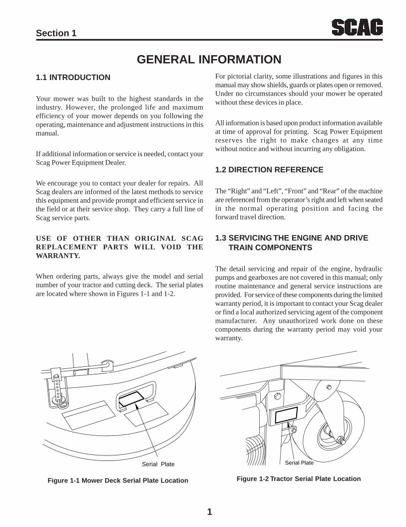
When ordering parts, always give the model and serialnumber of your tractor and cutting deck. The serial platesare located where shown in Figures 1-1 and 1-2.
For pictorial clarity, some illustrations and figures in thismanual may show shields, guards or plates open or removed.Under no circumstances should your mower be operatedwithout these devices in place.
All information is based upon product information availableat time of approval for printing. Scag Power Equipmentreserves the right to make changes at any timewithout notice and without incurring any obligation.
1.2 DIRECTION REFERENCE
The “Right” and “Left”, “Front” and “Rear” of the machineare referenced from the operator’s right and left when seatedin the normal operating position and facing theforward travel direction.
1.3 SERVICING THE ENGINE AND DRIVE TRAIN COMPONENTS
The detail servicing and repair of the engine, hydraulicpumps and gearboxes are not covered in this manual; onlyroutine maintenance and general service instructions areprovided. For service of these components during the limitedwarranty period, it is important to contact your Scag dealeror find a local authorized servicing agent of the componentmanufacturer. Any unauthorized work done on thesecomponents during the warranty period may void yourwarranty.
Figure 1-1 Mower Deck Serial Plate Location Figure 1-2 Tractor Serial Plate Location
Serial Plate Serial Plate

2
SAFETY INFORMATION2.1 INTRODUCTION
Your mower is only as safe as the operator. Carelessness oroperator error may result in serious bodily injury or death.Hazard control and accident prevention are dependent uponthe awareness, concern, prudence, and proper training ofthe personnel involved in the operation, transport,maintenance and storage of the equipment. Make sure everyoperator is properly trained and thoroughly familiar withall of the controls before operating the mower.
READ THIS OPERATOR’S MANUAL BEFOREATTEMPTING TO START YOUR MOWER.
A replacement manual is available from your authorizedScag Service Dealer or by Contacting Scag PowerEquipment, Service Department at P.O. Box 152, Mayville,WI 53050. There is a nominal charge of $2.00 for eachmanual. Please indicate the complete model and serialnumber of your Scag product.
2.2 SIGNAL WORDS
This symbol means “Attention! Become Alert! YourSafety is Involved!" The symbol is used with the followingsignal words to attract your attention to safety messagesfound on the decals and throughout this manual. Themessage that follows the symbol contains importantinformation about safety. To avoid injury and possible death,carefully read the message! Be sure to fully understandthe causes of possible injury or death.
Signal Word:
It is a distinctive word on safety decals and throughout thismanual that alerts the viewer to the existence and relativedegree of the hazard.
The signal word “WARNING” denotes a hazard exists onor near the machine that can result in injury or death ifproper precautions are not taken.
The signal word “DANGER” denotes that an extremelyhazardous situation exists on or near the machine that couldresult in high probability of death or irreparable injury ifproper precautions are not taken.
CAUTION:The signal word “CAUTION” is a reminder of safetypractices on or near the machine that could result in personalinjury if proper precautions are not taken.
Your safety and the safety of others depends significantlyupon your knowledge and understanding of all correctoperating practices and procedures of this machine.
2.3 BEFORE OPERATION CONSIDERATIONS
1. NEVER allow children to operate this riding mower.Do not allow adults to operate this machine withoutproper instructions.
2. DO NOT mow when children and/or others are present.
3. Clear the area to be mowed of objects that could bepicked up and thrown by the cutter blades.
4. DO NOT carry passengers.
5. DO NOT wear loose fitting clothing that could gettangled in moving parts. Do not operate the machinewearing shorts; always wear adequate protectiveclothing including long pants. Wearing safety glasses,safety shoes and a helmet is advisable and is requiredby some local ordinances and insurance regulations.
WARNING:
Section 2

3
6. Operator hearing protection is recommended,particularly for continuous operation of the mower.Wear suitable hearing protection. Prolonged exposureto loud noise can cause hearing impairment or loss.
7. Keep the machine and attachments in good operatingcondition. Keep all shields and safety devices in place.If a shield, safety device or decal is defective ordamaged, repair or replace it before operating themachine.
13. DO NOT operate without a chute deflector installed;keep the deflector in lowest possible position.
14. Check the blade mounting bolts at frequent intervalsfor proper tightness.
15. Make sure all hydraulic fluid connections are tight andall hydraulic hoses and lines are in good condition beforestarting the machine.
WARNING:This machine is equipped with an interlocksystem intended to protect the operator andothers from injury. This is accomplished bypreventing the engine from starting unless theoperator is seated in the seat, the deck drive isdisengaged, and the speed control is placed inthe neutral position. The system also shuts offthe engine if the operator leaves the seat withthe mower running and the speed control is notin the neutral postion. It will also shut off theengine if the hopper is raised with the cutter deckdrive engaged. Never operate equipment withthe interlock system disconnected ormalfunctioning.
8. Be sure interlock switches are functioning correctly.
9. Fuel is flammable; handle with care. Fill fuel tankoutdoors. Never fill indoors. Use a funnel or spout toinhibit spillage. Clean up any spillage before startingthe engine.
10. DO NOT add fuel to a running or hot engine. Anexplosion could occur. Allow engine to cool for severalminutes before adding fuel.
11. Keep flammable objects (cigarettes, matches, etc.), openflames and sparks away from fthe uel tank and fuelcontainer.
12. Equipment must comply with the latest requirementsper ANSI J137 and/or ANSI S279 when driven onpublic roads.
2.4 OPERATION CONSIDERATIONS
1. Know the function of all controls and how to stopquickly.
2. Reduce speed and exercise extreme caution on slopesand in sharp turns to prevent tipping or loss of control.Be especially cautious when changing directions onslopes.
WARNING:DO NOT operate on steep slopes. To check aslope, attempt to drive up it (with cutter deckdown). If machine can drive up the slope withoutthe wheels slipping, reduce speed and useextreme caution. ALWAYS FOLLOW OSHAAPPROVED OPERATION.
3. Do not stop or start suddenly. WHEN GOING UPHILL OR DOWN HILL, MOW UP AND DOWNTHE FACE OF SLOPES, NEVER ACROSS THEFACE.
4. When using any attachment, never direct the dischargeof material toward bystanders or allow anyone nearthe machine while in operation.
5. Before attempting to start the engine, disengage powerto the cutter deck and engage the parking brake.
6. If the mower discharge ever plugs, shut off the engine,remove the ignition key, and wait for all movement tostop before removing the obstruction. Do not use yourhand to dislodge the clogged discharge chute. Use astick or other device to remove clogged material.
Section 2

4
7. Be alert for holes, rocks, and roots in the terrain andother hidden hazards. Keep away from any dropoff.Beware of overhead obstructions (low limbs, etc.),underground obstacles (sprinklers, pipes, tree roots,etc.). Cautiously enter a new area. Be alert for hiddenhazards.
8. Disengage power to mower before backing up. Do notmow in reverse unless absolutely necessary and thenonly after observation of the entire area behind themower.
9. DO NOT turn sharply. Use care when backing up.
10. Watch for traffic when crossing roads or operating nearroadways.
11. Mow only in daylight or good artificial light.
12. Take all possible precautions when leaving the machineunattended, such as disengaging the mower, loweringthe attachments, setting the parking brake, stopping theengine, and removing the key.
13. Disengage power to the attachments when transportingor when not in use.
14. The machine and attachments should be stopped andinspected for damage after striking a foreign object,and damage should be repaired before restarting andoperating the machine.
15. DO NOT touch the engine or the muffler while theengine is running or immediately after stopping. Theseareas may be hot enough to cause a burn.
16. DO NOT run engine inside a building or confined areawithout proper ventilation. Exhaust fumes arehazardaous and could cause death.
2.5 MAINTENANCE CONSIDERATIONS
1. Never make adjustments to the machine with the enginerunning unless specifically instructed to do so. If theengine is running, keep hands, feet, and clothing awayfrom moving parts.
2. Remove the key from the ignition switch to preventaccidental starting of the engine when servicing oradjusting the machine.
3. Keep all nuts, bolts and screws tight to ensure themachine is in safe working condition. Check blademounting bolts frequently to be sure they are tight.
4. Do not change the engine governor settings or overspeedthe engine.
5. To reduce fire hazard, keep the engine free of grass,leaves, excessive grease and dirt.
6. Hydraulic fluid is under high pressure. Keep bodyand hands away from pinholes or nozzles that ejecthydraulic fluid under high pressure. Use only cardboardor paper to search for leaks.
7. Hydraulic fluid under high pressure may have sufficientforce to penetrate skin and cause serious injury. Ifhydraulic fluid is injected into the skin, it must besurgically removed within a few hours by a doctor organgrene may result.
Section 2

5
Section 2
2.6 SAFETY AND INSTRUCTIONAL DECALS
DANGERSPINNING BLADE
KEEP CLEAR
CONTACT CAN INJURE48071
ROTATING BLADES AND BELTSWARNING
KEEP HANDS, FEET & CLOTHING CLEARKEEP ALL GUARDS IN PLACESHUT OFF ENGINE & DISENGAGE BLADECLUTCH BEFORE SERVICINGCLEAR AREA OF DEBRIS BEFORE MOWINGUSE CAUTION IN DIRECTING DISCHARGEKEEP BYSTANDERS, CHILDREN & PETS AWAYREAD INSTRUCTION MANUAL BEFORE OPERATING
DO NOT OPERATE WITHOUT DISCHARGE CHUTE, MULCHINGKIT, OR ENTIRE GRASS CATCHER INSTALLED 481040
CAUTIONBEFORE OPERATING
READ OPERATORSMANUAL AND SAFETY
INSTRUCTIONS
KEEP BYSTANDERS AWAY
CAUTION
WARNINGINSTALL BELT COVER BEFORE
OPERATING MACHINEREAD OPERATOR'S MANUAL 481039
6
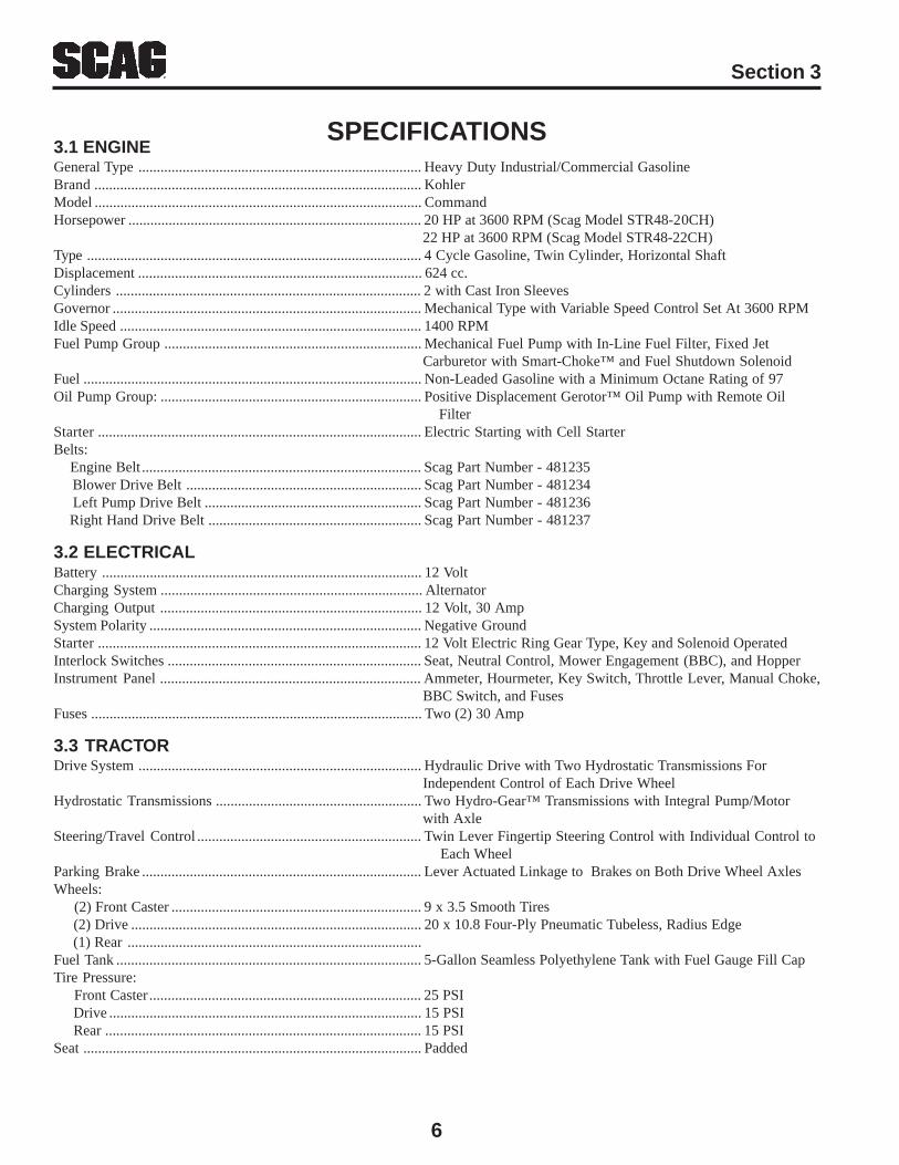
SPECIFICATIONS3.1 ENGINEGeneral Type ............................................................................. Heavy Duty Industrial/Commercial GasolineBrand......................................................................................... KohlerModel ......................................................................................... CommandHorsepower ................................................................................ 20 HP at 3600 RPM (Scag Model STR48-20CH)
22 HP at 3600 RPM (Scag Model STR48-22CH)Type ........................................................................................... 4 Cycle Gasoline, Twin Cylinder, Horizontal ShaftDisplacement ............................................................................. 624 cc.Cylinders ................................................................................... 2 with Cast Iron SleevesGovernor .................................................................................... Mechanical Type with Variable Speed Control Set At 3600 RPMIdle Speed .................................................................................. 1400 RPMFuel Pump Group ...................................................................... Mechanical Fuel Pump with In-Line Fuel Filter, Fixed Jet
Carburetor with Smart-Choke™ and Fuel Shutdown SolenoidFuel ............................................................................................ Non-Leaded Gasoline with a Minimum Octane Rating of 97Oil Pump Group: ....................................................................... Positive Displacement Gerotor™ Oil Pump with Remote Oil
FilterStarter........................................................................................ Electric Starting with Cell StarterBelts: Engine Belt ............................................................................ Scag Part Number - 481235 Blower Drive Belt ................................................................ Scag Part Number - 481234 Left Pump Drive Belt ........................................................... Scag Part Number - 481236 Right Hand Drive Belt .......................................................... Scag Part Number - 481237
3.2 ELECTRICALBattery ....................................................................................... 12 VoltCharging System ....................................................................... AlternatorCharging Output ....................................................................... 12 Volt, 30 AmpSystem Polarity .......................................................................... Negative GroundStarter........................................................................................ 12 Volt Electric Ring Gear Type, Key and Solenoid OperatedInterlock Switches ..................................................................... Seat, Neutral Control, Mower Engagement (BBC), and HopperInstrument Panel ....................................................................... Ammeter, Hourmeter, Key Switch, Throttle Lever, Manual Choke,
BBC Switch, and FusesFuses .......................................................................................... Two (2) 30 Amp
3.3 TRACTORDrive System ............................................................................. Hydraulic Drive with Two Hydrostatic Transmissions For
Independent Control of Each Drive WheelHydrostatic Transmissions ........................................................ Two Hydro-Gear™ Transmissions with Integral Pump/Motor
with AxleSteering/Travel Control ............................................................. Twin Lever Fingertip Steering Control with Individual Control to
Each WheelParking Brake ............................................................................ Lever Actuated Linkage to Brakes on Both Drive Wheel AxlesWheels: (2) Front Caster .................................................................... 9 x 3.5 Smooth Tires (2) Drive ............................................................................... 20 x 10.8 Four-Ply Pneumatic Tubeless, Radius Edge (1) Rear ................................................................................Fuel Tank ................................................................................... 5-Gallon Seamless Polyethylene Tank with Fuel Gauge Fill CapTire Pressure: Front Caster.......................................................................... 25 PSI Drive ..................................................................................... 15 PSI Rear ...................................................................................... 15 PSISeat ............................................................................................ Padded
Section 3
7
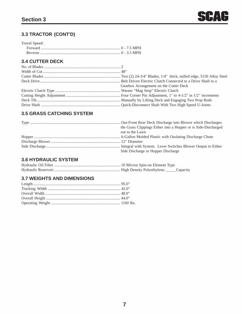
3.3 TRACTOR (CONT'D)
Travel Speed: Forward ................................................................................ 0 - 7.5 MPH Reverse ................................................................................. 0 - 3.5 MPH
3.4 CUTTER DECKNo. of Blades ............................................................................. 2Width of Cut .............................................................................. 48"Cutter Blades ............................................................................. Two (2) 24-3/4" Blades, 1/4" thick, milled edge, 5150 Alloy SteelDeck Drive ................................................................................. Belt Driven Electric Clutch Connected to a Drive Shaft to a
Gearbox Arrangement on the Cutter DeckElectric Clutch Type .................................................................. Warner “Mag Stop” Electric ClutchCutting Height Adjustment ....................................................... Four Corner Pin Adjustment, 1" to 4-1/2" in 1/2" incrementsDeck Tilt .................................................................................... Manually by Lifting Deck and Engaging Two Prop RodsDrive Shaft ................................................................................ Quick-Disconnect Shaft With Two High Speed U-Joints
3.5 GRASS CATCHING SYSTEM
Type ........................................................................................... Out-Front Rear Deck Discharge into Blower which Dischargesthe Grass Clippings Either into a Hopper or is Side-Dischargedout to the Lawn
Hopper ....................................................................................... 6-Gallon Molded Plastic with Osolating Discharge ChuteDischarge Blower ...................................................................... 12" DiameterSide Discharge........................................................................... Integral with System. Lever Switches Blower Output to Either
Side Discharge or Hopper Discharge
3.6 HYDRAULIC SYSTEMHydraulic Oil Filter ................................................................... 10 Micron Spin-on Element TypeHydraulic Reservoir ................................................................... High Density Polyethylene; _____Capacity
3.7 WEIGHTS AND DIMENSIONSLength ........................................................................................ 95.0"Tracking Width ......................................................................... 42.0"Overall Width ............................................................................ 48.0"Overall Height ........................................................................... 44.0"Operating Weight ...................................................................... 1160 lbs.
Section 3

8
Section 4
OPERATING INSTRUCTIONS
Do not attempt to operate this mower unless youhave read this manual. Learn the location andpurpose of all controls and instruments before youoperate this mower.
4.1 CONTROLS AND INSTRUMENT IDENTIFICATION
Before operating the mower, familiarize yourself with allmower and engine controls. Knowing the location,function and operation of these controls is important forsafe and efficient operation of the mower.
CAUTION:1. Ignition Switch (Figure 4-1). The ignition switch is
used to start the engine and has three positions; OFF,ON, and START.
2. Mower Deck Switch (Figure 4-1). Used to engageand disengage the mower drive system. Pulling theswitch lever up and then pushing the switch leverforward will engage the deck drive. Pulling theswitch lever back will disengage the deck drive.
3. Engine Choke Control (Figure 4-1). Used to start acold engine.
4. Engine Throttle Control (Figure 4-1). Used tocontrol the engine speed. Pushing the lever forwardincreases engine speed. Pulling the lever backdecreases engine speed. Full back position is theIDLE position. Full forward is the cutting position.
Figure 4-1 Controls and Instruments
CAUTIONBEFORE OPERATING
READ OPERATORSMANUAL AND SAFETY
INSTRUCTIONS
KEEP BYSTANDERS AWAY
CAUTION
CH
OK
E
4813
48
alja
lefj
airjf
;o3r
faf
krjf
;wso
rgf
alja
lefj
airjf
;o3r
fal
jale
fjai
rjf;o
3rf
OFF
OFF
OFF
PU
LLU
PA
ND
PU
SH
FOR
WA
RD
TOE
NG
AG
E
MO
WE
RD
EC
KO
NO
N
STA
RT
PU
LLB
AC
KTO
DIS
EN
GA
GE
OFF
4812
39
MO
WE
RD
EC
KO
FF
Left Steering Control Right Steering Control
Parking Brake Control
Speed Control
Mower Deck Switch
Ignition Switch
Hourmeter
Voltmeter
EngineThrottleControl
EngineChokeControl
Fuel Gauge
Fuses
9
Section 4
5. Ammeter (Figure 4-1). Indicates the condition ofthe charging system. When the engine is running theneedle should be at the positive end of the meter. Ifthe needle is on the negative end of the meter, thisindicates a discharge condition and the machineshould be taken in for service.
6. Hourmeter (Figure 4-1). Indicates the number ofhours the engine has been operated. It operateswhenever the ignition switch key is in the ONposition. It can be used to keep track of maintenanceintervals and the amount of time required to performvarious tasks.
7. Fuse Holders (Figure 4-1). Two 20-amp fusesprotect the mower’s electrical system. To replacefuses, pull fuse out of the socket and install a newfuse.
8. Left Steering Control (Figure 4-1). Used to controlthe mower's left wheel when traveling forward orreverse.
9. Right Steering Control (Figure 4-1). Used tocontrol the mower's right wheel when travelingforward or reverse.
10. Parking Brake Control (Figure 4-1). Used toengage and disengage the parking brakes. Pull thelever back and lock in place to engage the parkingbrakes. Pull the lever back and move to the left todisengage the parking brakes.
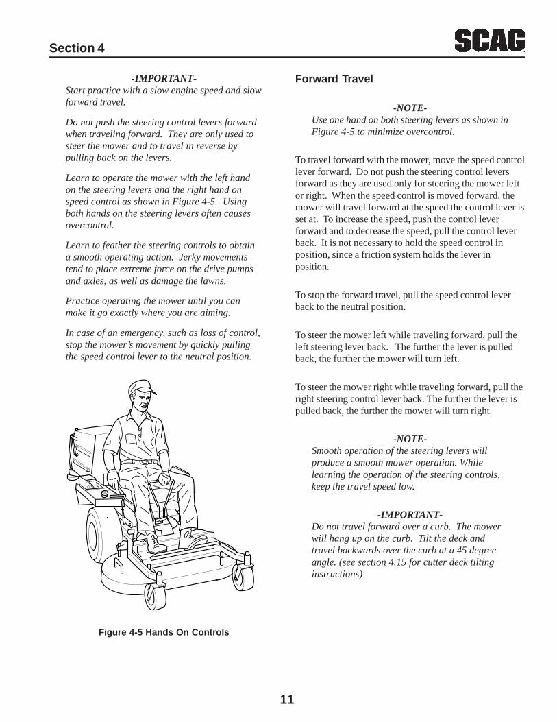
11. Fuel Tank Gauge (Figure 4-1 & 4-4). Indicates theamount of fuel in the fuel tank.
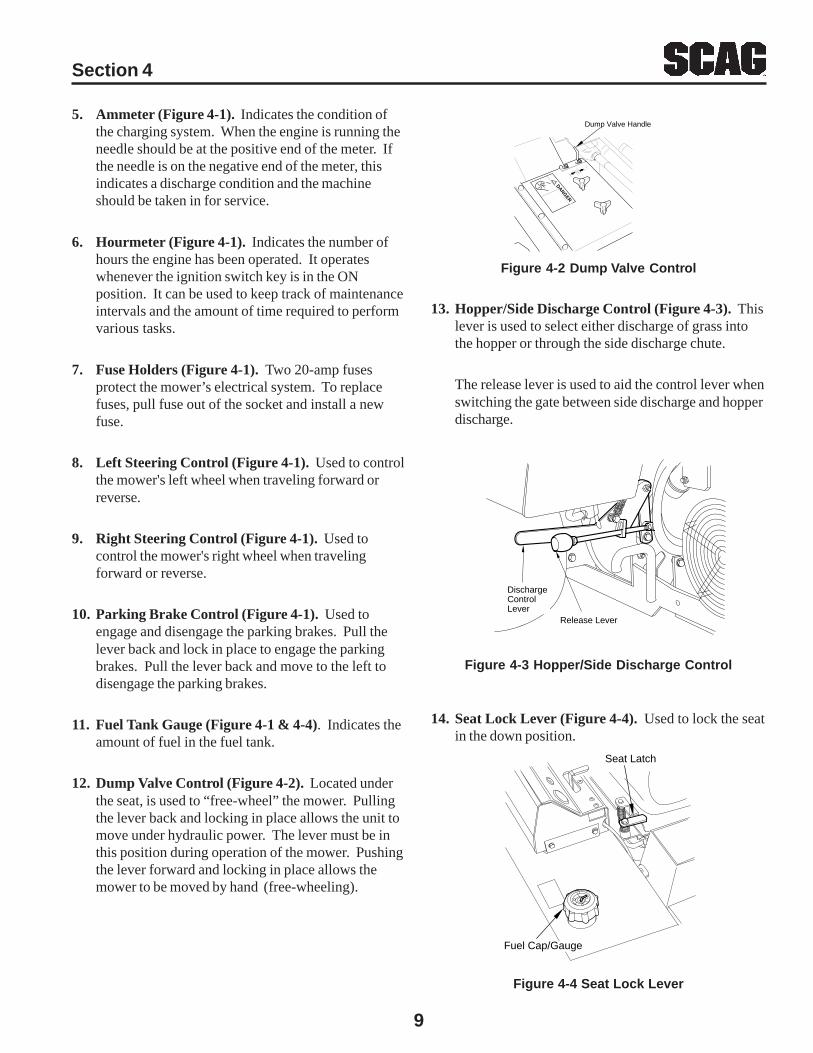
12. Dump Valve Control (Figure 4-2). Located underthe seat, is used to “free-wheel” the mower. Pullingthe lever back and locking in place allows the unit tomove under hydraulic power. The lever must be inthis position during operation of the mower. Pushingthe lever forward and locking in place allows themower to be moved by hand (free-wheeling).
Figure 4-4 Seat Lock Lever
DANGER
Dump Valve Handle
Figure 4-2 Dump Valve Control
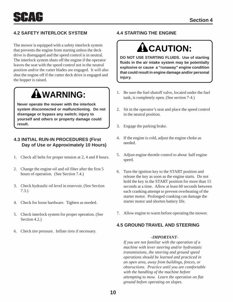
13. Hopper/Side Discharge Control (Figure 4-3). Thislever is used to select either discharge of grass intothe hopper or through the side discharge chute.
The release lever is used to aid the control lever whenswitching the gate between side discharge and hopperdischarge.
Discharge ControlLever
Release Lever
Figure 4-3 Hopper/Side Discharge Control
14. Seat Lock Lever (Figure 4-4). Used to lock the seatin the down position.
Seat Latch
Fuel Cap/Gauge
10
Section 4
4.2 SAFETY INTERLOCK SYSTEM
The mower is equipped with a safety interlock systemthat prevents the engine from starting unless the deckdrive is disengaged and the speed control is in neutral.The interlock system shuts off the engine if the operatorleaves the seat with the speed control not in the neutralposition and/or the cutter blades are engaged. It will alsoshut the engine off if the cutter deck drive is engaged andthe hopper is raised.
4.4 STARTING THE ENGINE
DO NOT USE STARTING FLUIDS. Use of startingfluids in the air intake system may be potentiallyexplosive or cause a “runaway” engine conditionthat could result in engine damage and/or personalinjury.
1. Be sure the fuel shutoff valve, located under the fueltank, is completely open. (See section 7-4.)
2. Sit in the operator’s seat and place the speed controlin the neutral position.
3. Engage the parking brake.
4. If the engine is cold, adjust the engine choke asneeded.
5. Adjust engine throttle control to about half enginespeed.
6. Turn the ignition key to the START position andrelease the key as soon as the engine starts. Do nothold the key in the START position for more than 15seconds at a time. Allow at least 60 seconds betweeneach cranking attempt to prevent overheating of thestarter motor. Prolonged cranking can damage thestarter motor and shorten battery life.
7. Allow engine to warm before operating the mower.
4.5 GROUND TRAVEL AND STEERING
-IMPORTANT-If you are not familiar with the operation of amachine with lever steering and/or hydrostatictransmissions, the steering and ground speedoperations should be learned and practiced inan open area, away from buildings, fences, orobstructions. Practice until you are comfortablewith the handling of the machine beforeattempting to mow. Learn the operation on flatground before operating on slopes.
CAUTION:
WARNING:Never operate the mower with the interlocksystem disconnected or malfunctioning. Do notdisengage or bypass any switch; injury toyourself and others or property damage couldresult.
4.3 INITIAL RUN-IN PROCEDURES (First Day of Use or Approximately 10 Hours)
1. Check all belts for proper tension at 2, 4 and 8 hours.
2. Change the engine oil and oil filter after the first 5hours of operation. (See Section 7.4.)
3. Check hydraulic oil level in reservoir. (See Section7.3.)
4. Check for loose hardware. Tighten as needed.
5. Check interlock system for proper operation. (SeeSection 4.2.)
6. Check tire pressure. Inflate tires if necessary.
11
Section 4
-IMPORTANT-Start practice with a slow engine speed and slowforward travel.
Do not push the steering control levers forwardwhen traveling forward. They are only used tosteer the mower and to travel in reverse bypulling back on the levers.
Learn to operate the mower with the left handon the steering levers and the right hand onspeed control as shown in Figure 4-5. Usingboth hands on the steering levers often causesovercontrol.
Learn to feather the steering controls to obtaina smooth operating action. Jerky movementstend to place extreme force on the drive pumpsand axles, as well as damage the lawns.
Practice operating the mower until you canmake it go exactly where you are aiming.
In case of an emergency, such as loss of control,stop the mower’s movement by quickly pullingthe speed control lever to the neutral position.
Figure 4-5 Hands On Controls
Forward Travel
-NOTE-Use one hand on both steering levers as shown inFigure 4-5 to minimize overcontrol.
To travel forward with the mower, move the speed controllever forward. Do not push the steering control leversforward as they are used only for steering the mower leftor right. When the speed control is moved forward, themower will travel forward at the speed the control lever isset at. To increase the speed, push the control leverforward and to decrease the speed, pull the control leverback. It is not necessary to hold the speed control inposition, since a friction system holds the lever inposition.
To stop the forward travel, pull the speed control leverback to the neutral position.
To steer the mower left while traveling forward, pull theleft steering lever back. The further the lever is pulledback, the further the mower will turn left.
To steer the mower right while traveling forward, pull theright steering control lever back. The further the lever ispulled back, the further the mower will turn right.
-NOTE-Smooth operation of the steering levers willproduce a smooth mower operation. Whilelearning the operation of the steering controls,keep the travel speed low.
-IMPORTANT-Do not travel forward over a curb. The mowerwill hang up on the curb. Tilt the deck andtravel backwards over the curb at a 45 degreeangle. (see section 4.15 for cutter deck tiltinginstructions)
12
Section 4
Reverse Travel
Before backing up, observe the rear for personsand obstructions. Clear the area before backingup. Possible injury or property damage couldoccur.
Disengage power to the mower before backing up.Do not mow in reverse unless absolutelynecessary and then only after observation of theentire area behind the mower.
To travel in reverse, pull both handles all the way back.Keep the travel speed low while traveling in reverse.
-NOTE-The mower will not travel straight in reverse.Slight adjustments must be made using thesteering controls.
To steer left while traveling in reverse, allow the leftsteering control lever to move forward. The further thecontrol is allowed to move forward, the further the mowerwill turn left.
To steer right while traveling in reverse, allow the rightsteering control lever to move forward. The further thecontrol is allowed to move forward, the further the mowerwill turn right.
To stop the reverse travel, place the speed control lever inthe neutral position and allow the steering control leversto return to the neutral position. If the mower is to beparked, engage the parking brake.
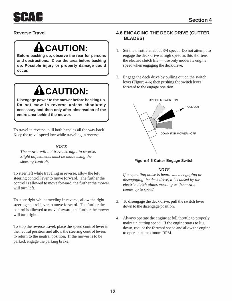
4.6 ENGAGING THE DECK DRIVE (CUTTER BLADES)
1. Set the throttle at about 3/4 speed. Do not attempt toengage the deck drive at high speed as this shortensthe electric clutch life — use only moderate enginespeed when engaging the deck drive.
2. Engage the deck drive by pulling out on the switchlever (Figure 4-6) then pushing the switch leverforward to the engage position.
CAUTION:
CAUTION:
Figure 4-6 Cutter Engage Switch
-NOTE-If a squealing noise is heard when engaging ordisengaging the deck drive, it is caused by theelectric clutch plates meshing as the mowercomes up to speed.
3. To disengage the deck drive, pull the switch leverdown to the disengage position.
4. Always operate the engine at full throttle to properlymaintain cutting speed. If the engine starts to lugdown, reduce the forward speed and allow the engineto operate at maximum RPM.
PULL OUT
UP FOR MOWER - ON
DOWN FOR MOWER - OFF
13
Section 4
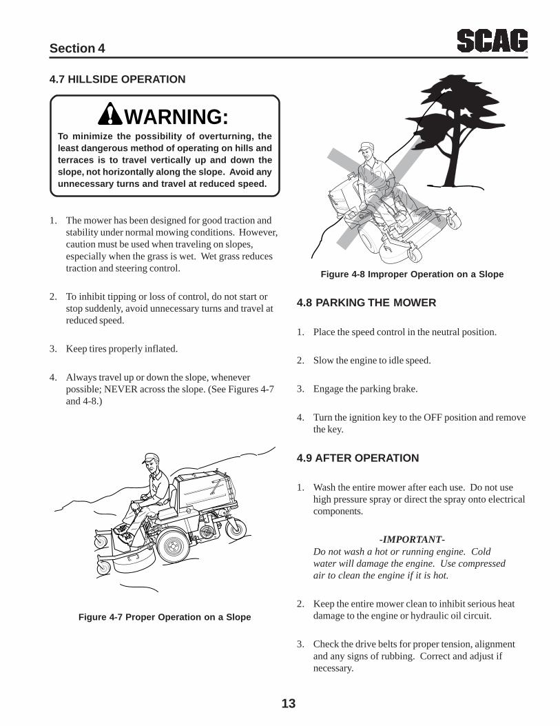
4.7 HILLSIDE OPERATION
To minimize the possibility of overturning, theleast dangerous method of operating on hills andterraces is to travel vertically up and down theslope, not horizontally along the slope. Avoid anyunnecessary turns and travel at reduced speed.
1. The mower has been designed for good traction andstability under normal mowing conditions. However,caution must be used when traveling on slopes,especially when the grass is wet. Wet grass reducestraction and steering control.
2. To inhibit tipping or loss of control, do not start orstop suddenly, avoid unnecessary turns and travel atreduced speed.
3. Keep tires properly inflated.
4. Always travel up or down the slope, wheneverpossible; NEVER across the slope. (See Figures 4-7and 4-8.)
WARNING:
Figure 4-7 Proper Operation on a Slope
Figure 4-8 Improper Operation on a Slope
4.8 PARKING THE MOWER
1. Place the speed control in the neutral position.
2. Slow the engine to idle speed.
3. Engage the parking brake.
4. Turn the ignition key to the OFF position and removethe key.
4.9 AFTER OPERATION
1. Wash the entire mower after each use. Do not usehigh pressure spray or direct the spray onto electricalcomponents.
-IMPORTANT-Do not wash a hot or running engine. Coldwater will damage the engine. Use compressedair to clean the engine if it is hot.
2. Keep the entire mower clean to inhibit serious heatdamage to the engine or hydraulic oil circuit.
3. Check the drive belts for proper tension, alignmentand any signs of rubbing. Correct and adjust ifnecessary.

14
Section 4
4. Fill the fuel tank with fresh, clean fuel at the end ofevery day of operation.
5. Check the tire pressure. Inflate tires if necessary.
4.10 HOPPER/SIDE DISCHARGE OPERATION
A control lever located on the left side of the tractorselects either hopper discharge or side discharge to theoutside. When the lever is placed in the hopper position(Figure 4-9), the side discharge is covered and the hopperdischarge is opened. When the lever is placed in the sidedischarge position (Figure 4-10), the hopper discharge iscovered and the side discharge is opened.
-NOTE-If the control lever sticks, push the release lever tofree it.
Grass Catching Operation
Never leave grass clippings in the hopper aftermowing. Wet or damp clippings will generate heatas they decompose which may cause spontaneouscombustion to occur.
1. Place the hopper/side discharge control lever in thehopper discharge position (Figure 4-9).
2. With the hopper lowered, engage the deck drive.When the deck drive is engaged, the grass deliveryspout, which is designed to distribute the grassclippings through the inside of the hopper, will beginto oscillate. If the spout does not oscillate, do not usethe grass catcher. Use the side discharge and thenhave the oscillating spout system repaired.
-NOTE-The mower has an interlock switch that willprevent the mower from starting if the hopper isin the raised position. This interlock switch willalso shut the engine off if the hopper is raisedwhile the engine is running and the deck drive isengaged.
3. Proceed to mow the lawn until the hopper is full. Ifyour mower is not equipped with the optional hopperfull alarm to tell you when the hopper is full, checkthe hopper frequently when first using the grasscatcher. After operating with the grass catcher forawhile, experience will tell you when the hopper isfull.
4. When dumping the hopper into a disposal area:
CAUTION:
Figure 4-9 Hopper Operation Position
Figure 4-10 Side Discharge Operation Position
Release Lever in ThisPosition for Hopper Discharge
Release Lever in ThisPosition for Side Disharge
WARNING:Never operate the grass catcher with thehopper back door open. Objects can bethrown out the spout of the hopper with aforce that can cause injury to bystanders orproperty damage.
A.Disengage the deck drive.
15
Section 4
4.11 REMOVING CLOGGED MATERIAL
ROTATING BLOWER BLADES
NEVER PUT YOUR HANDS INTO THE BLOWERDISCHARGE CHUTE FOR ANY REASON! Shut offthe engine and remove the key and only then usea stick or similar object to remove material ifclogging has occurred.
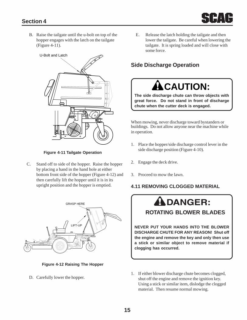
B. Raise the tailgate until the u-bolt on top of thehopper engages with the latch on the tailgate(Figure 4-11).
Figure 4-11 Tailgate Operation
C. Stand off to side of the hopper. Raise the hopperby placing a hand in the hand hole at eitherbottom front side of the hopper (Figure 4-12) andthen carefully lift the hopper until it is in itsupright position and the hopper is emptied.
GRASP HERE
LIFT-UP
D. Carefully lower the hopper.
Figure 4-12 Raising The Hopper
U-Bolt and Latch
E. Release the latch holding the tailgate and thenlower the tailgate. Be careful when lowering thetailgate. It is spring loaded and will close withsome force.
The side discharge chute can throw objects withgreat force. Do not stand in front of dischargechute when the cutter deck is engaged.
When mowing, never discharge toward bystanders or
CAUTION:
Side Discharge Operation
1. If either blower discharge chute becomes clogged,shut off the engine and remove the ignition key.Using a stick or similar item, dislodge the cloggedmaterial. Then resume normal mowing.
buildings. Do not allow anyone near the machine whilein operation.
1. Place the hopper/side discharge control lever in theside discharge position (Figure 4-10).
2. Engage the deck drive.
3. Proceed to mow the lawn.
16
Section 4
4.12 MOVING MOWER WITH ENGINE STOPPED
To “free-wheel” or move the mower around without theengine running, place the dump valve handle in theFREE-WHEEL position (Figure 4-2). Disengage theparking brake and move the mower by hand. The levermust be returned to the DRIVE position to drive themower.
4.13 RECOMMENDATIONS FOR MOWING
1. Do not mow with dull blades. A dull blade will teargrass, resulting in poor lawn appearance andrequiring extra power.
2. Direct the side discharge away from sidewalks orstreets to minimize cleanup of clippings. Whenmowing close to obstacles, direct the discharge awayfrom the obstacles to reduce the chance of propertydamage by thrown objects.
3. Cut grass when it is dry and not too tall. Do not cutgrass too short (cut off 1/3 or less of existing grassfor best appearance). Mow frequently.
4. Keep mower and discharge system clean.
5. When mowing wet or tall grass, mow the grass twice.
Raise the mower to the highest setting for the firstpass and then make a second pass to the desiredheight.
6. Use a slow travel speed for trimming purposes.
7. Operate the engine at or near full throttle for bestcutting. Mowing with a lower RPM causes themower to tear the grass. The engine is designed to beoperated at full speed.
8. Use the alternate stripe pattern for best lawnappearance. Vary the direction of the stripe eachtime the grass is mowed to avoid wear patterns in thegrass.
2. If the blower intake becomes clogged, there could bea distinct change in the sound of the blower and/orthe mower deck will begin to leave a trail of glassclippings. The clogging will generally develop in theback of the mower deck in the opening of the blowerchute. When clogging occurs at this point, it'susually caused by something restricting the flowthroughout the entire system and the system shouldbe checked if a pattern develops.
3. Check the following:
A. Check that the blades are properly installed forcorrect rotation. See Section 7.
B. Check that the cutting height is not too low.When cutting thick, tall grass, lower cuttingheight settings tend to restrict the airflow movinginto and under the deck.
C. Check that the deck housing and baffling is freeof grass and dirt buildup. Some material buildupcan be tolerated, but when a buildup occurs thatrestricts the flow of air and grass clippings, themower deck must be cleaned.
D. Check that the blades have enough flat section atthe blade tip. Sharpening of the blades willremove this flat section and if too much isremoved, the air lift capability of the blade isgreatly reduced. Replace the blades if more than1/3 of blade is removed at the blade tip. Seesection 7.10.
E. Check the discharge chutes for accumulation ofdirt and material that would restrict flow. Cleanthe discharge chutes as described above.
F. Check the elbow inside the hopper for a buildupof material in the radius.
G. Check that the screen in the hopper is notplugged with materials. If plugged, remove andclean screen as described in section 7.13.
H. Remember, anything that restricts airflow ormaterial flow along the entire path from themower deck to the hopper can cause clogging.
17
Section 4
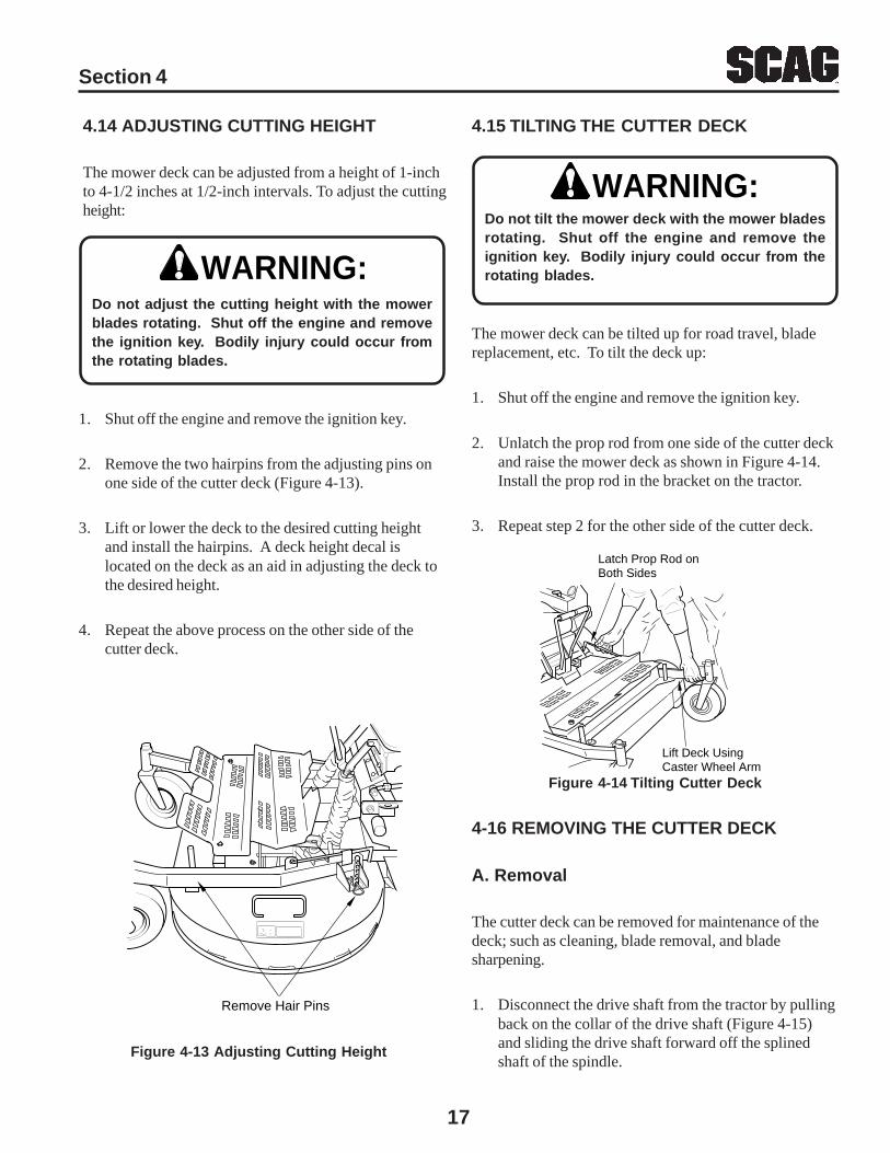
4.14 ADJUSTING CUTTING HEIGHT
The mower deck can be adjusted from a height of 1-inchto 4-1/2 inches at 1/2-inch intervals. To adjust the cuttingheight:
4.15 TILTING THE CUTTER DECK
WARNING:Do not tilt the mower deck with the mower bladesrotating. Shut off the engine and remove theignition key. Bodily injury could occur from therotating blades.
The mower deck can be tilted up for road travel, bladereplacement, etc. To tilt the deck up:
1. Shut off the engine and remove the ignition key.
2. Unlatch the prop rod from one side of the cutter deckand raise the mower deck as shown in Figure 4-14.Install the prop rod in the bracket on the tractor.
3. Repeat step 2 for the other side of the cutter deck.
Do not adjust the cutting height with the mowerblades rotating. Shut off the engine and removethe ignition key. Bodily injury could occur fromthe rotating blades.
1. Shut off the engine and remove the ignition key.
2. Remove the two hairpins from the adjusting pins onone side of the cutter deck (Figure 4-13).
3. Lift or lower the deck to the desired cutting heightand install the hairpins. A deck height decal islocated on the deck as an aid in adjusting the deck tothe desired height.
4. Repeat the above process on the other side of thecutter deck.
Lift Deck UsingCaster Wheel Arm
Latch Prop Rod onBoth Sides
Figure 4-14 Tilting Cutter Deck
4-16 REMOVING THE CUTTER DECK
A. Removal
The cutter deck can be removed for maintenance of thedeck; such as cleaning, blade removal, and bladesharpening.
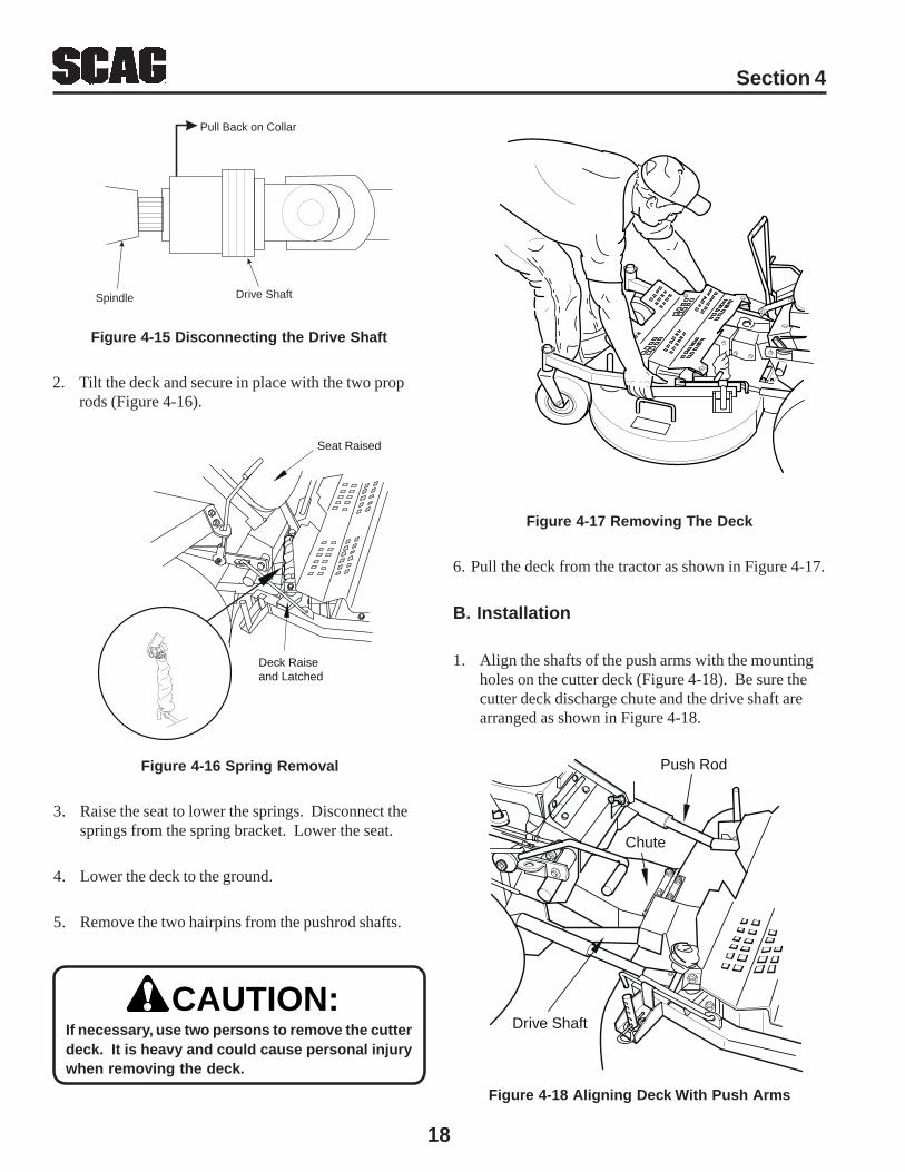
1. Disconnect the drive shaft from the tractor by pullingback on the collar of the drive shaft (Figure 4-15)and sliding the drive shaft forward off the splinedshaft of the spindle.
WARNING:
Remove Hair Pins
Figure 4-13 Adjusting Cutting Height
18
Section 4
Figure 4-16 Spring Removal
3. Raise the seat to lower the springs. Disconnect thesprings from the spring bracket. Lower the seat.
4. Lower the deck to the ground.
5. Remove the two hairpins from the pushrod shafts.
CAUTION:If necessary, use two persons to remove the cutterdeck. It is heavy and could cause personal injurywhen removing the deck.
Pull Back on Collar
Drive ShaftSpindle
Figure 4-15 Disconnecting the Drive Shaft
2. Tilt the deck and secure in place with the two proprods (Figure 4-16).
Seat Raised
Deck Raiseand Latched
Figure 4-17 Removing The Deck
6. Pull the deck from the tractor as shown in Figure 4-17.
B. Installation
1. Align the shafts of the push arms with the mountingholes on the cutter deck (Figure 4-18). Be sure thecutter deck discharge chute and the drive shaft arearranged as shown in Figure 4-18.
Figure 4-18 Aligning Deck With Push Arms
Push Rod
Chute
Drive Shaft
19
Section 4
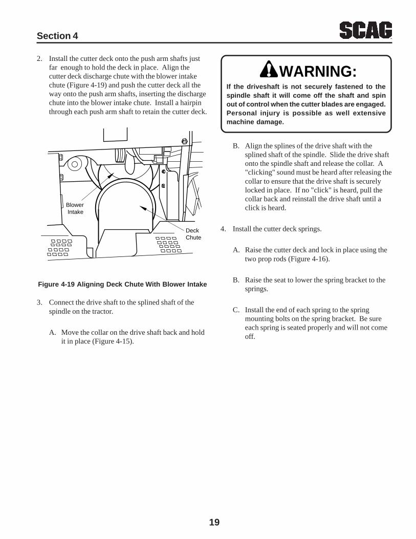
2. Install the cutter deck onto the push arm shafts justfar enough to hold the deck in place. Align thecutter deck discharge chute with the blower intakechute (Figure 4-19) and push the cutter deck all theway onto the push arm shafts, inserting the dischargechute into the blower intake chute. Install a hairpinthrough each push arm shaft to retain the cutter deck.
Blower Intake
Deck Chute
Figure 4-19 Aligning Deck Chute With Blower Intake
3. Connect the drive shaft to the splined shaft of thespindle on the tractor.
A. Move the collar on the drive shaft back and holdit in place (Figure 4-15).
WARNING:If the driveshaft is not securely fastened to thespindle shaft it will come off the shaft and spinout of control when the cutter blades are engaged.Personal injury is possible as well extensivemachine damage.
B. Align the splines of the drive shaft with thesplined shaft of the spindle. Slide the drive shaftonto the spindle shaft and release the collar. A"clicking" sound must be heard after releasing thecollar to ensure that the drive shaft is securelylocked in place. If no "click" is heard, pull thecollar back and reinstall the drive shaft until aclick is heard.
4. Install the cutter deck springs.
A. Raise the cutter deck and lock in place using thetwo prop rods (Figure 4-16).
B. Raise the seat to lower the spring bracket to thesprings.
C. Install the end of each spring to the springmounting bolts on the spring bracket. Be sureeach spring is seated properly and will not comeoff.
Section 5
20
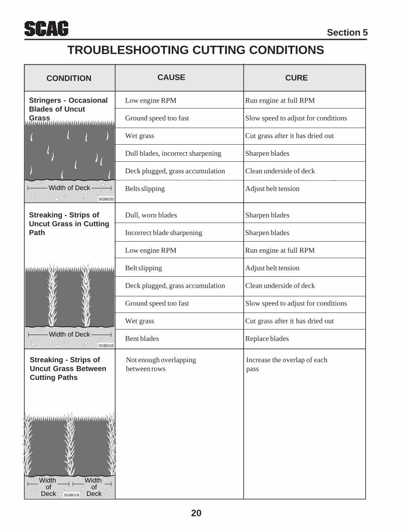
Stringers - Occasional Low engine RPM Run engine at full RPMBlades of UncutGrass Ground speed too fast Slow speed to adjust for conditions
Wet grass Cut grass after it has dried out
Dull blades, incorrect sharpening Sharpen blades
Deck plugged, grass accumulation Clean underside of deck
Belts slipping Adjust belt tension
Streaking - Strips of Dull, worn blades Sharpen bladesUncut Grass in CuttingPath Incorrect blade sharpening Sharpen blades
Low engine RPM Run engine at full RPM
Belt slipping Adjust belt tension
Deck plugged, grass accumulation Clean underside of deck
Ground speed too fast Slow speed to adjust for conditions
Wet grass Cut grass after it has dried out
Bent blades Replace bladesWidth of Deck
SGB018
CONDITION CAUSE CURE
Width of Deck
SGB020
Width of
Deck
Width of
DeckSGB019
Streaking - Strips of Not enough overlapping Increase the overlap of eachUncut Grass Between between rows passCutting Paths
TROUBLESHOOTING CUTTING CONDITIONS

Section 5
21
Uneven Cut on Flat Lift worn from blade Replace bladeGround - WavyHigh-Low Blade upside down Mount with cutting edge towardAppearance, groundScalloped Cut, orRough Contour Deck plugged, grass accumulation Clean underside of deck
Too much blade angle (deck pitch) Adjust pitch and level
Deck mounted improperly See your authorized SCAG dealer
Bent spindle area See your authorized SCAG dealer
Dull blade Sharpen blade
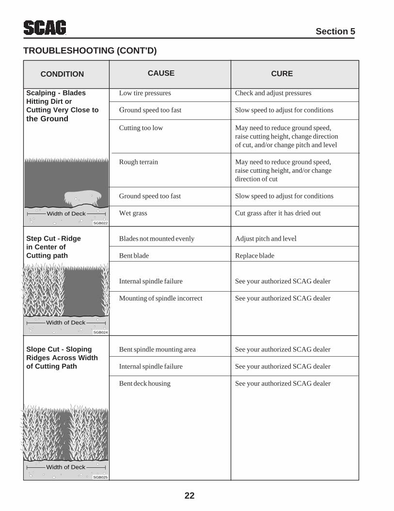
TROUBLESHOOTING (CONT'D)
Sloping Ridge Across Tire pressures not equal Check and adjust tire pressureWidth of Cutting Path
Wheels uneven Check and adjust tire pressure
Deck mounted incorrectly See your authorized SCAG dealer
Deck not level side-to side Check for level and correct
CONDITION CAUSE CURE
Uneven Cut on Uneven ground May need to reduce ground speed,Uneven Ground - raise cutting height, and/or changeWavy Appearance, direction of cutHigh-Low ScallopedCut, or Rough Contour
Width of Deck
SGB020
Width of Deck
SGB021
Width of Deck
SGB023
Section 5
22
Scalping - Blades Low tire pressures Check and adjust pressuresHitting Dirt orCutting Very Close to Ground speed too fast Slow speed to adjust for conditionsthe Ground
Cutting too low May need to reduce ground speed,raise cutting height, change directionof cut, and/or change pitch and level
Rough terrain May need to reduce ground speed,raise cutting height, and/or changedirection of cut
Ground speed too fast Slow speed to adjust for conditions
Wet grass Cut grass after it has dried out
Step Cut - Ridge Blades not mounted evenly Adjust pitch and levelin Center ofCutting path Bent blade Replace blade
Internal spindle failure See your authorized SCAG dealer
Mounting of spindle incorrect See your authorized SCAG dealer
Slope Cut - Sloping Bent spindle mounting area See your authorized SCAG dealerRidges Across Widthof Cutting Path Internal spindle failure See your authorized SCAG dealer
Bent deck housing See your authorized SCAG dealer
CONDITION CAUSE CURE
Width of Deck
SGB024
Width of Deck
SGB025
Width of Deck
SGB022
TROUBLESHOOTING (CONT'D)
Section 6
23
ADJUSTMENTS6.1 PARKING BRAKE ADJUSTMENT
WARNING:Do not operate the mower if the parking brake isnot operable. Possible severe injury couldresult.
The parking brake linkage should be adjusted wheneverthe parking brake lever is placed in the “ENGAGE”position and the parking brake will not prevent the mowerfrom moving. Adjustments can be made to the brakelinkage. If the following procedures do not allow you toengage the parking brake properly, contact your Scagdealer for further brake adjustments.
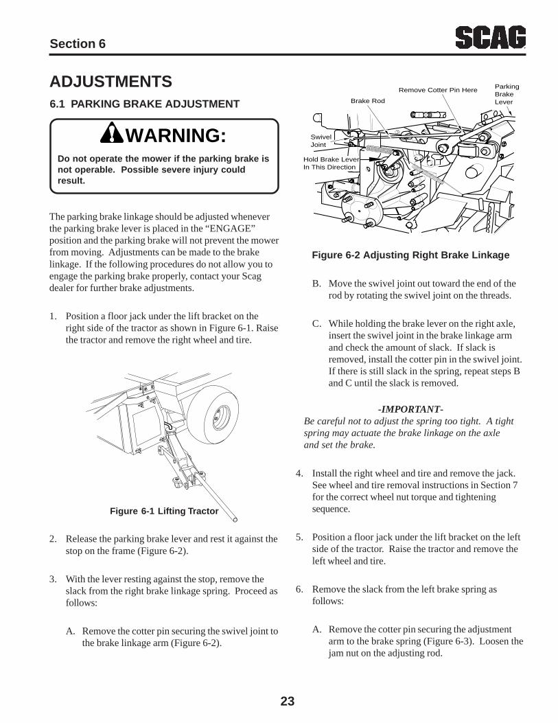
1. Position a floor jack under the lift bracket on theright side of the tractor as shown in Figure 6-1. Raisethe tractor and remove the right wheel and tire.
Figure 6-1 Lifting Tractor
2. Release the parking brake lever and rest it against thestop on the frame (Figure 6-2).
3. With the lever resting against the stop, remove theslack from the right brake linkage spring. Proceed asfollows:
A. Remove the cotter pin securing the swivel joint tothe brake linkage arm (Figure 6-2).
Remove Cotter Pin Here
Brake Rod
ParkingBrakeLever
SwivelJoint
Hold Brake LeverIn This Direction
Figure 6-2 Adjusting Right Brake Linkage
B. Move the swivel joint out toward the end of therod by rotating the swivel joint on the threads.
C. While holding the brake lever on the right axle,insert the swivel joint in the brake linkage armand check the amount of slack. If slack isremoved, install the cotter pin in the swivel joint.If there is still slack in the spring, repeat steps Band C until the slack is removed.
-IMPORTANT-Be careful not to adjust the spring too tight. A tightspring may actuate the brake linkage on the axleand set the brake.
4. Install the right wheel and tire and remove the jack.See wheel and tire removal instructions in Section 7for the correct wheel nut torque and tighteningsequence.
5. Position a floor jack under the lift bracket on the leftside of the tractor. Raise the tractor and remove theleft wheel and tire.
6. Remove the slack from the left brake spring asfollows:
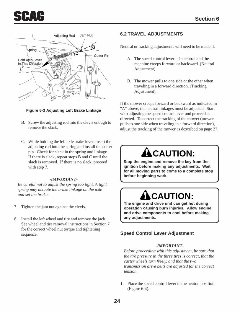
A. Remove the cotter pin securing the adjustmentarm to the brake spring (Figure 6-3). Loosen thejam nut on the adjusting rod.
Section 6
24
6.2 TRAVEL ADJUSTMENTS
Neutral or tracking adjustments will need to be made if:
A. The speed control lever is in neutral and themachine creeps forward or backward. (NeutralAdjustment)
B. The mower pulls to one side or the other whentraveling in a forward direction. (TrackingAdjustment).
If the mower creeps forward or backward as indicated in"A" above, the neutral linkages must be adjusted. Startwith adjusting the speed control lever and proceed asdirected. To correct the tracking of the mower (mowerpulls to one side when traveling in a forward direction),adjust the tracking of the mower as described on page 27.
Cotter Pin
Adjusting Rod Jam Nut
Hold Axle LeverIn This Direction
Spring
Figure 6-3 Adjusting Left Brake Linkage
B. Screw the adjusting rod into the clevis enough toremove the slack.
C. While holding the left axle brake lever, insert theadjusting rod into the spring and install the cotterpin. Check for slack in the spring and linkage.If there is slack, repeat steps B and C until theslack is removed. If there is no slack, proceedwith step 7.
-IMPORTANT-Be careful not to adjust the spring too tight. A tightspring may actuate the brake linkage on the axleand set the brake.
7. Tighten the jam nut against the clevis.
8. Install the left wheel and tire and remove the jack.See wheel and tire removal instructions in Section 7for the correct wheel nut torque and tighteningsequence.
Stop the engine and remove the key from theignition before making any adjustments. Waitfor all moving parts to come to a complete stopbefore beginning work.
CAUTION:
CAUTION:The engine and drive unit can get hot duringoperation causing burn injuries. Allow engineand drive components to cool before makingany adjustments.
Speed Control Lever Adjustment
-IMPORTANT-Before proceeding with this adjustment, be sure thatthe tire pressure in the three tires is correct, that thecaster wheels turn freely, and that the twotransmission drive belts are adjusted for the correcttension.
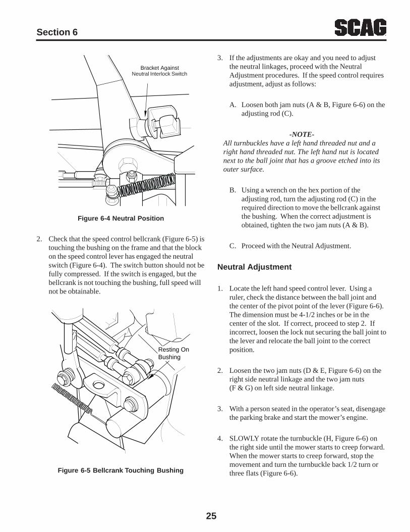
1. Place the speed control lever in the neutral position(Figure 6-4).
Section 6
25
3. If the adjustments are okay and you need to adjustthe neutral linkages, proceed with the NeutralAdjustment procedures. If the speed control requiresadjustment, adjust as follows:
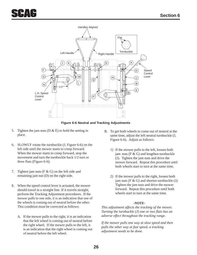
A. Loosen both jam nuts (A & B, Figure 6-6) on theadjusting rod (C).
-NOTE-All turnbuckles have a left hand threaded nut and aright hand threaded nut. The left hand nut is locatednext to the ball joint that has a groove etched into itsouter surface.
B. Using a wrench on the hex portion of theadjusting rod, turn the adjusting rod (C) in therequired direction to move the bellcrank againstthe bushing. When the correct adjustment isobtained, tighten the two jam nuts (A & B).
C. Proceed with the Neutral Adjustment.
Neutral Adjustment
1. Locate the left hand speed control lever. Using aruler, check the distance between the ball joint andthe center of the pivot point of the lever (Figure 6-6).The dimension must be 4-1/2 inches or be in thecenter of the slot. If correct, proceed to step 2. Ifincorrect, loosen the lock nut securing the ball joint tothe lever and relocate the ball joint to the correctposition.
2. Loosen the two jam nuts (D & E, Figure 6-6) on theright side neutral linkage and the two jam nuts(F & G) on left side neutral linkage.
3. With a person seated in the operator’s seat, disengagethe parking brake and start the mower’s engine.
4. SLOWLY rotate the turnbuckle (H, Figure 6-6) onthe right side until the mower starts to creep forward.When the mower starts to creep forward, stop themovement and turn the turnbuckle back 1/2 turn orthree flats (Figure 6-6).
Figure 6-4 Neutral Position
2. Check that the speed control bellcrank (Figure 6-5) istouching the bushing on the frame and that the blockon the speed control lever has engaged the neutralswitch (Figure 6-4). The switch button should not befully compressed. If the switch is engaged, but thebellcrank is not touching the bushing, full speed willnot be obtainable.
Resting OnBushing
Figure 6-5 Bellcrank Touching Bushing
Bracket AgainstPressure SwitchNeutral Interlock Switch
Section 6
26
4.5"
D
A
E
B
CH
J K
L
P
Q
N
M
Left Handle Right Handle
SpeedControlLever
Handles Aligned
F
G
N
L.H. SpeedControlLever
Flat
Turnbuckle
B. To get both wheels to come out of neutral at thesame time, adjust the left neutral turnbuckle (J,Figure 6-6). Adjust as follows:
1) If the mower pulls to the left, loosen bothjam nuts (F & G) and lengthen turnbuckle(J). Tighten the jam nuts and drive themower forward. Repeat this procedure untilboth wheels start to turn at the same time.
2) If the mower pulls to the right, loosen bothjam nuts (F & G) and shorten turnbuckle (J).Tighten the jam nuts and drive the mowerforward. Repeat this procedure until bothwheels start to turn at the same time.
-NOTE-This adjustment affects the tracking of the mower.Turning the turnbuckle (J) one or two flats has anadverse effect throughout the tracking range.
If the mower pulls one way at slow speed and thenpulls the other way at fast speed, a trackingadjustment needs to be done.
Figure 6-6 Neutral and Tracking Adjustments
5. Tighten the jam nuts (D & E) to hold the setting inplace.
6. SLOWLY rotate the turnbuckle (J, Figure 6-6) on theleft side until the mower starts to creep forward.When the mower starts to creep forward, stop themovement and turn the turnbuckle back 1/2 turn orthree flats (Figure 6-6).
7. Tighten jam nuts (F & G) on the left side andremaining jam nut (D) on the right side.
8. When the speed control lever is actuated, the mowershould travel in a straight line. If it travels straight,perform the Tracking Adjustment procedures. If themower pulls to one side, it is an indication that one ofthe wheels is coming out of neutral before the other.This condition must be corrected as follows:
A. If the mower pulls to the right, it is an indicationthat the left wheel is coming out of neutral beforethe right wheel. If the mower pulls to the left, itis an indication that the right wheel is coming outof neutral before the left wheel.
Section 6
27
Tracking Adjustment
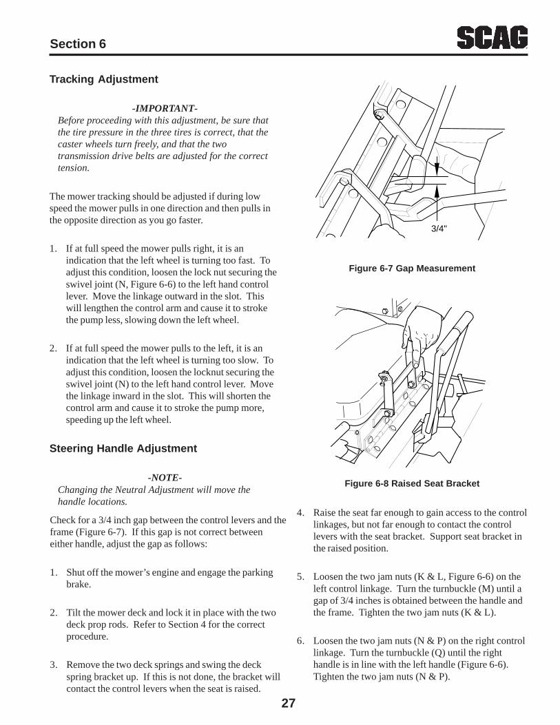
-IMPORTANT-Before proceeding with this adjustment, be sure thatthe tire pressure in the three tires is correct, that thecaster wheels turn freely, and that the twotransmission drive belts are adjusted for the correcttension.
The mower tracking should be adjusted if during lowspeed the mower pulls in one direction and then pulls inthe opposite direction as you go faster.
1. If at full speed the mower pulls right, it is anindication that the left wheel is turning too fast. Toadjust this condition, loosen the lock nut securing theswivel joint (N, Figure 6-6) to the left hand controllever. Move the linkage outward in the slot. Thiswill lengthen the control arm and cause it to strokethe pump less, slowing down the left wheel.
2. If at full speed the mower pulls to the left, it is anindication that the left wheel is turning too slow. Toadjust this condition, loosen the locknut securing theswivel joint (N) to the left hand control lever. Movethe linkage inward in the slot. This will shorten thecontrol arm and cause it to stroke the pump more,speeding up the left wheel.
Steering Handle Adjustment
-NOTE-Changing the Neutral Adjustment will move thehandle locations.
3/4"
Figure 6-7 Gap Measurement
Figure 6-8 Raised Seat Bracket
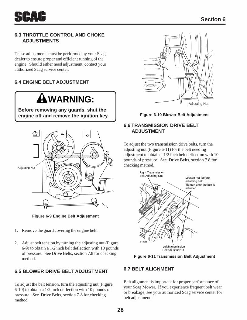
4. Raise the seat far enough to gain access to the controllinkages, but not far enough to contact the controllevers with the seat bracket. Support seat bracket inthe raised position.
5. Loosen the two jam nuts (K & L, Figure 6-6) on theleft control linkage. Turn the turnbuckle (M) until agap of 3/4 inches is obtained between the handle andthe frame. Tighten the two jam nuts (K & L).
6. Loosen the two jam nuts (N & P) on the right controllinkage. Turn the turnbuckle (Q) until the righthandle is in line with the left handle (Figure 6-6).Tighten the two jam nuts (N & P).
Check for a 3/4 inch gap between the control levers and theframe (Figure 6-7). If this gap is not correct betweeneither handle, adjust the gap as follows:
1. Shut off the mower’s engine and engage the parkingbrake.
2. Tilt the mower deck and lock it in place with the twodeck prop rods. Refer to Section 4 for the correctprocedure.
3. Remove the two deck springs and swing the deckspring bracket up. If this is not done, the bracket willcontact the control levers when the seat is raised.
Section 6
28
6.3 THROTTLE CONTROL AND CHOKE ADJUSTMENTS
These adjustments must be performed by your Scagdealer to ensure proper and efficient running of theengine. Should either need adjustment, contact yourauthorized Scag service center.
6.4 ENGINE BELT ADJUSTMENT
Figure 6-11 Transmission Belt Adjustment
6.7 BELT ALIGNMENT
Belt alignment is important for proper performance ofyour Scag Mower. If you experience frequent belt wearor breakage, see your authorized Scag service center forbelt adjustment.
Figure 6-10 Blower Belt Adjustment
6.6 TRANSMISSION DRIVE BELT ADJUSTMENT
To adjust the two transmission drive belts, turn theadjusting nut (Figure 6-11) for the belt needingadjustment to obtain a 1/2 inch belt deflection with 10pounds of pressure. See Drive Belts, section 7.8 forchecking method.
1. Remove the guard covering the engine belt.
2. Adjust belt tension by turning the adjusting nut (Figure6-9) to obtain a 1/2 inch belt deflection with 10 poundsof pressure. See Drive Belts, section 7.8 for checkingmethod.
6.5 BLOWER DRIVE BELT ADJUSTMENT
To adjust the belt tension, turn the adjusting nut (Figure6-10) to obtain a 1/2 inch deflection with 10 pounds ofpressure. See Drive Belts, section 7-8 for checkingmethod.
WARNING:Before removing any guards, shut theengine off and remove the ignition key.
Adjusting Nut
Figure 6-9 Engine Belt Adjustment
Adjusting Nut
Right TransmissionBelt Adjusting Nut
LeftTransmissionBeltAdjustingNut
Loosen nut beforeadjusting belt. Tighten after the belt is adjusted.
STR611

Section 7
29
MAINTENANCE
7.1 MAINTENANCE CHART - RECOMMENDED SERVICE INTERVALS
HOURSBreak-In 8 40 100 200 500 Procedure Comments(First 10)
X Check all hardware for tightness
X Check hydraulic oil level See paragraph 7.3
X Check all belts for tightness See paragraph 7.8
X Change engine oil and filter See paragraph 7.4(First 5)
X Fill fuel tank before starting Use unleaded gasolinewith a minimumoctane rating of 87
X Check engine oil level See paragraph 7.4
X *Clean mower See paragraph 7.14
X Check condition of blades See paragraph 7.9
X Apply grease to fittings See paragraph 7.2
X *Remove dust from air cleaner See paragraph 7.6 dust cup
X Clean screen in hopper See paragraph 7.11
X *Check/clean air intake See paragraph 7.6
X Check tire pressure See paragraph 7.10
X Check battery electrolyte level, See paragraph 7.7clean battery posts and cables
X Check belt tension See paragraph 7.8
X Apply grease to fittings See paragraph 7.2
X Change engine oil See paragraph 7.4
X *Clean air cleaner element See paragraph 7.6
X Check engine belts for tightness See paragraph 7.8
X Check lubricant in gearboxes See paragraph 7.13
30
Section 7
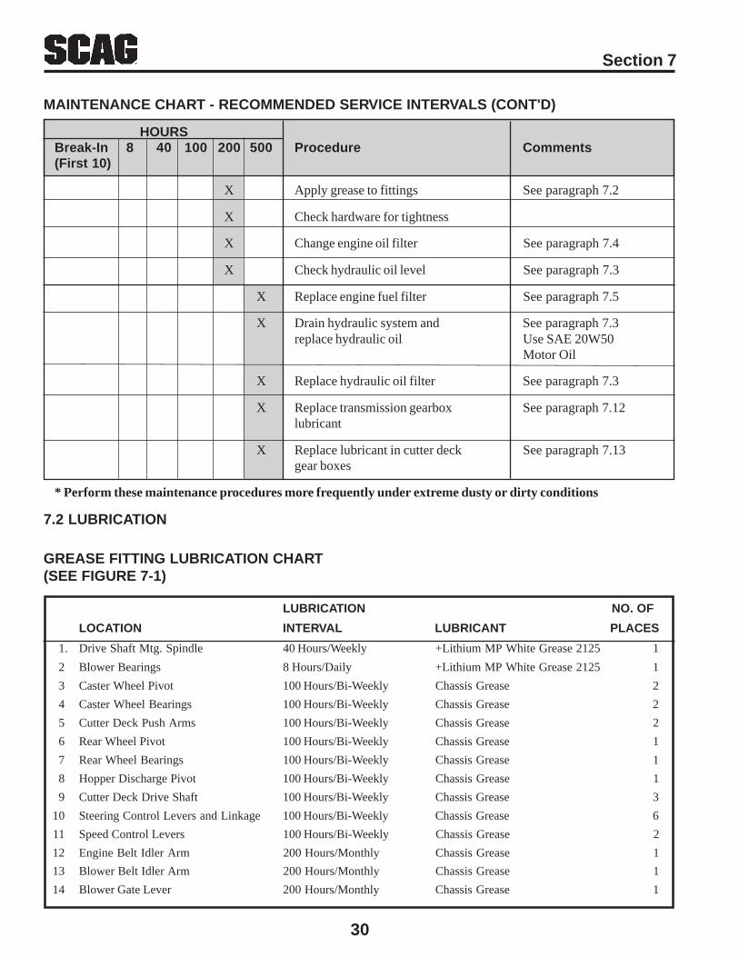
MAINTENANCE CHART - RECOMMENDED SERVICE INTERVALS (CONT'D)
HOURSBreak-In 8 40 100 200 500 Procedure Comments(First 10)
X Apply grease to fittings See paragraph 7.2
X Check hardware for tightness
X Change engine oil filter See paragraph 7.4
X Check hydraulic oil level See paragraph 7.3
X Replace engine fuel filter See paragraph 7.5
X Drain hydraulic system and See paragraph 7.3replace hydraulic oil Use SAE 20W50
Motor Oil
X Replace hydraulic oil filter See paragraph 7.3
X Replace transmission gearbox See paragraph 7.12lubricant
X Replace lubricant in cutter deck See paragraph 7.13gear boxes
* Perform these maintenance procedures more frequently under extreme dusty or dirty conditions
7.2 LUBRICATION
GREASE FITTING LUBRICATION CHART(SEE FIGURE 7-1)
LUBRICATION NO. OF
LOCATION INTERVAL LUBRICANT PLACES
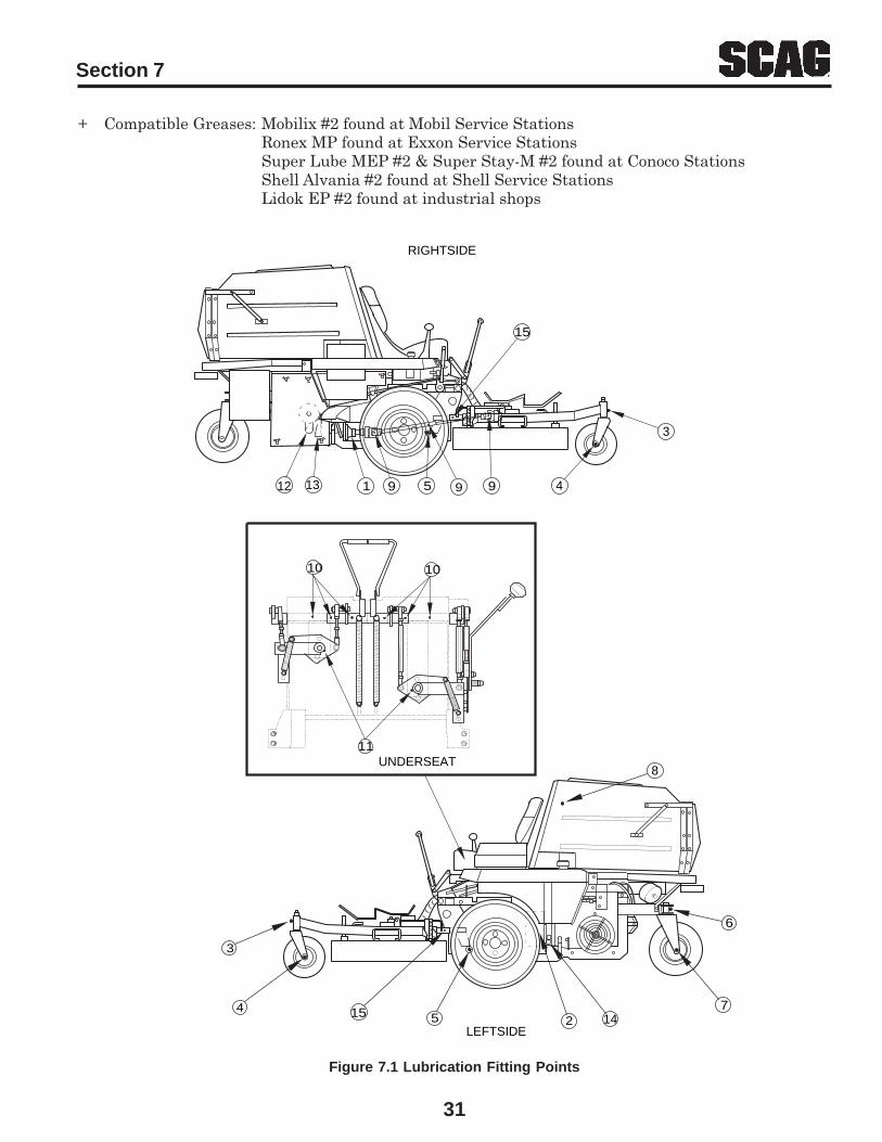
1. Drive Shaft Mtg. Spindle 40 Hours/Weekly +Lithium MP White Grease 2125 1
2 Blower Bearings 8 Hours/Daily +Lithium MP White Grease 2125 1
3 Caster Wheel Pivot 100 Hours/Bi-Weekly Chassis Grease 2
4 Caster Wheel Bearings 100 Hours/Bi-Weekly Chassis Grease 2
5 Cutter Deck Push Arms 100 Hours/Bi-Weekly Chassis Grease 2
6 Rear Wheel Pivot 100 Hours/Bi-Weekly Chassis Grease 1
7 Rear Wheel Bearings 100 Hours/Bi-Weekly Chassis Grease 1
8 Hopper Discharge Pivot 100 Hours/Bi-Weekly Chassis Grease 1
9 Cutter Deck Drive Shaft 100 Hours/Bi-Weekly Chassis Grease 3
10 Steering Control Levers and Linkage 100 Hours/Bi-Weekly Chassis Grease 6
11 Speed Control Levers 100 Hours/Bi-Weekly Chassis Grease 2
12 Engine Belt Idler Arm 200 Hours/Monthly Chassis Grease 1
13 Blower Belt Idler Arm 200 Hours/Monthly Chassis Grease 1
14 Blower Gate Lever 200 Hours/Monthly Chassis Grease 1
Section 7
31
+ Compatible Greases: Mobilix #2 found at Mobil Service StationsRonex MP found at Exxon Service StationsSuper Lube MEP #2 & Super Stay-M #2 found at Conoco StationsShell Alvania #2 found at Shell Service StationsLidok EP #2 found at industrial shops
Figure 7.1 Lubrication Fitting Points
RIGHTSIDE
LEFTSIDE
4
3
14
12 13
UNDERSEAT8
3
4 15 5 27
6
1 59 9 9
10 10
11
15

32
Section 7
7.3 HYDRAULIC SYSTEM
A. Checking Hydraulic Oil Level
The hydraulic oil level should be checked after the first10 hours of operation. Thereafter, check the oil afterevery 200 hours of machine operation or monthly,whichever occurs first.
-IMPORTANT-If the oil level is consistently low, check forleaks and correct immediately.
1. Wipe dirt and contaminants from around thereservoir cap. Remove the cap from the hydraulic oilreservoir.
2. Visually check the level of hydraulic oil. Hydraulicoil must be at least 2-1/4" inches from top of thefiller neck. If the level cannot be determined visually,use a clean tape measure to check the level. If thefluid is low, add 20W50 motor oil. DO NOToverfill; (overfilling the oil reservoir may cause oilseepage).
3. Clean the fill cap and install it onto the reservoir.
Hydraulic OIl Reservoir
Drain Cap
Figure 7-2 Hydraulic Oil Reservoir
B. Changing Hydraulic Oil
The hydraulic oil should be changed after every 500hours or annually, whichever occurs first. The oilshould also be changed if the color of the fluid hasbecome black or milky. A black color and/or arancid odor usually indicates possible overheating ofthe oil, and a milky color usually indicates water inthe hydraulic oil.
-NOTE-
The hydraulic oil should be changed if younotice the presence of water or a rancidodor to the hydraulic oil.
1. Park the mower on a level surface and stop theengine.
2. Place a suitable container under the hydraulic oilreservoir. Remove the cap from the tee installed inthe hydraulic oil reservoir. (See Figure 7-2). Allowthe fluid to drain into the container and properlydiscard it.
3. Install the cap onto the tee and be sure it is tight.
4. Remove the fill cap from the reservoir and fill thereservoir to 2-1/4" inches from the top of the fillerneck with 20W50 motor oil.
5. Start the engine and drive forward and backward fortwo minutes. Check the oil level in the reservoir. Ifnecessary, add oil to the reservoir.
6. Replace the reservoir fill cap.
C. Changing Hydraulic Oil Filter Element
The hydraulic oil filter should be changed after every 500hours of operation or annually, whichever occurs first.
1. Remove the oil filter element (Figure 7-3) andproperly discard it. Fill the new filter with clean oiland install the filter. Hand tighten only.
Section 7
33
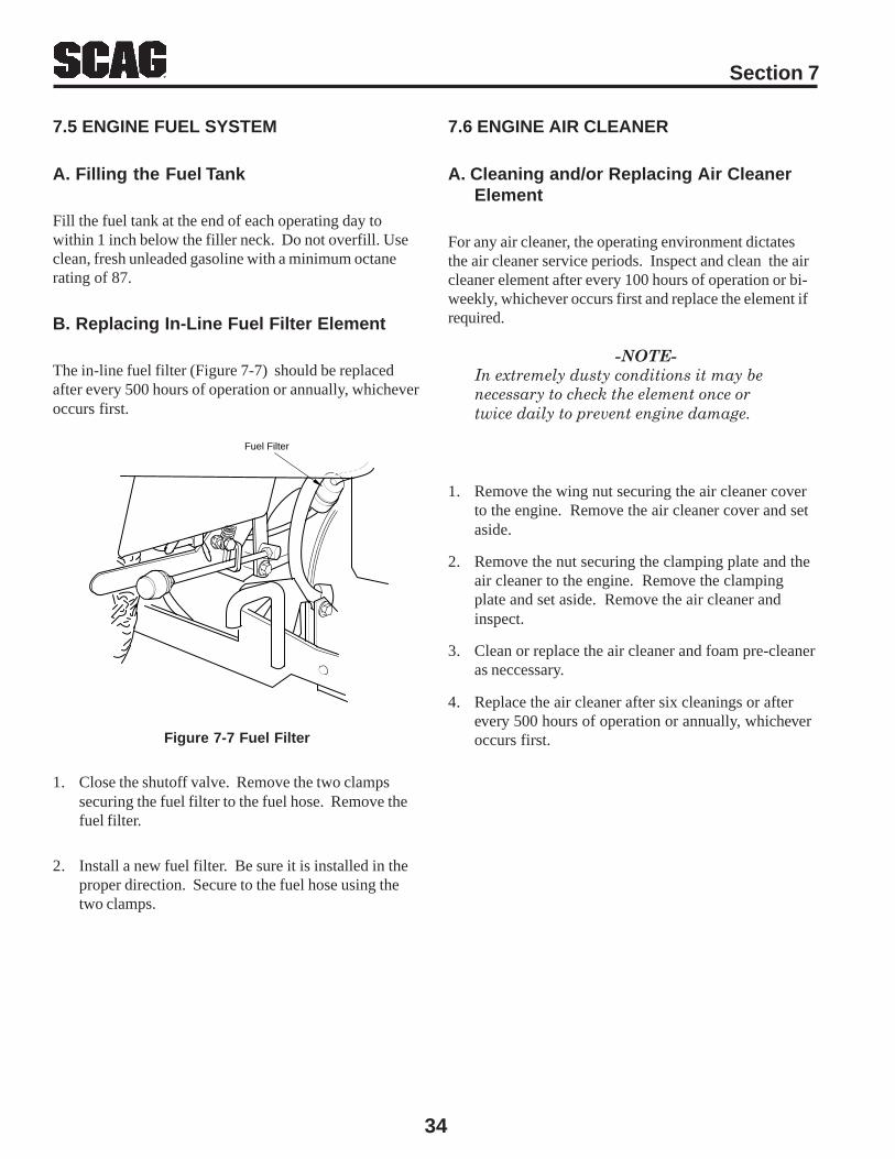
B. Changing Engine Crankcase Oil
After the first 5 hours of operation, change the enginecrankcase oil and replace the oil filter. Thereafter,change the engine crankcase oil after every 100 hours ofoperation or bi-weekly, whichever occurs first. Refer tothe Engine Operator’s Manual furnished with this mowerfor instructions.
Figure 7-6 Engine Oil Filter LocationFigure 7-4 Engine Fill Stick
Figure 7-5 Drain Plug Location
C. Changing Engine Oil Filter
After the first 5 hours of operation, replace the engine oilfilter. Thereafter, replace the oil filter after every 200 hoursof operation or every month, whichever occurs first. Referto Engine Operator’s Manual for instructions.
Drain Plug
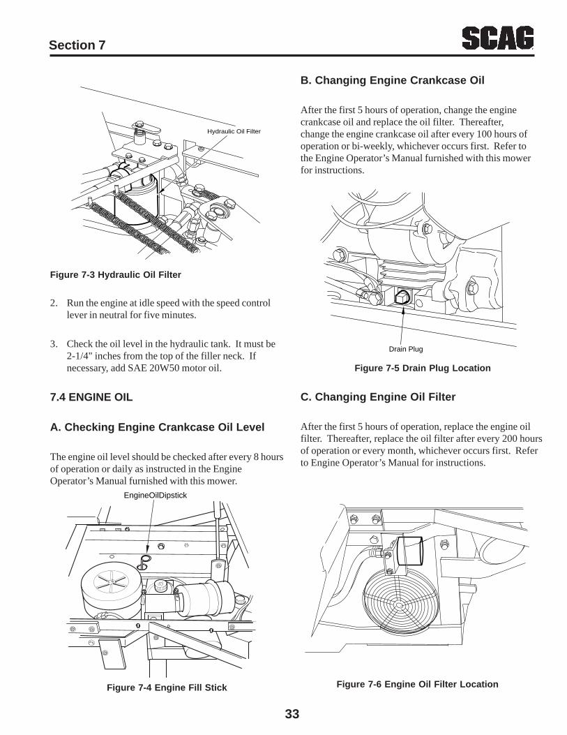
Figure 7-3 Hydraulic Oil Filter
2. Run the engine at idle speed with the speed controllever in neutral for five minutes.
3. Check the oil level in the hydraulic tank. It must be2-1/4" inches from the top of the filler neck. Ifnecessary, add SAE 20W50 motor oil.
7.4 ENGINE OIL
A. Checking Engine Crankcase Oil Level
The engine oil level should be checked after every 8 hoursof operation or daily as instructed in the EngineOperator’s Manual furnished with this mower.
Hydraulic Oil Filter
EngineOilDipstick
34
Section 7
7.5 ENGINE FUEL SYSTEM
A. Filling the Fuel Tank
Fill the fuel tank at the end of each operating day towithin 1 inch below the filler neck. Do not overfill. Useclean, fresh unleaded gasoline with a minimum octanerating of 87.
B. Replacing In-Line Fuel Filter Element
The in-line fuel filter (Figure 7-7) should be replacedafter every 500 hours of operation or annually, whicheveroccurs first.
7.6 ENGINE AIR CLEANER
A. Cleaning and/or Replacing Air CleanerElement
For any air cleaner, the operating environment dictatesthe air cleaner service periods. Inspect and clean the aircleaner element after every 100 hours of operation or bi-weekly, whichever occurs first and replace the element ifrequired.
-NOTE-In extremely dusty conditions it may benecessary to check the element once ortwice daily to prevent engine damage.
1. Remove the wing nut securing the air cleaner coverto the engine. Remove the air cleaner cover and setaside.
2. Remove the nut securing the clamping plate and theair cleaner to the engine. Remove the clampingplate and set aside. Remove the air cleaner andinspect.
3. Clean or replace the air cleaner and foam pre-cleaneras neccessary.
4. Replace the air cleaner after six cleanings or afterevery 500 hours of operation or annually, whicheveroccurs first.Figure 7-7 Fuel Filter
1. Close the shutoff valve. Remove the two clampssecuring the fuel filter to the fuel hose. Remove thefuel filter.
2. Install a new fuel filter. Be sure it is installed in theproper direction. Secure to the fuel hose using thetwo clamps.
Fuel Filter
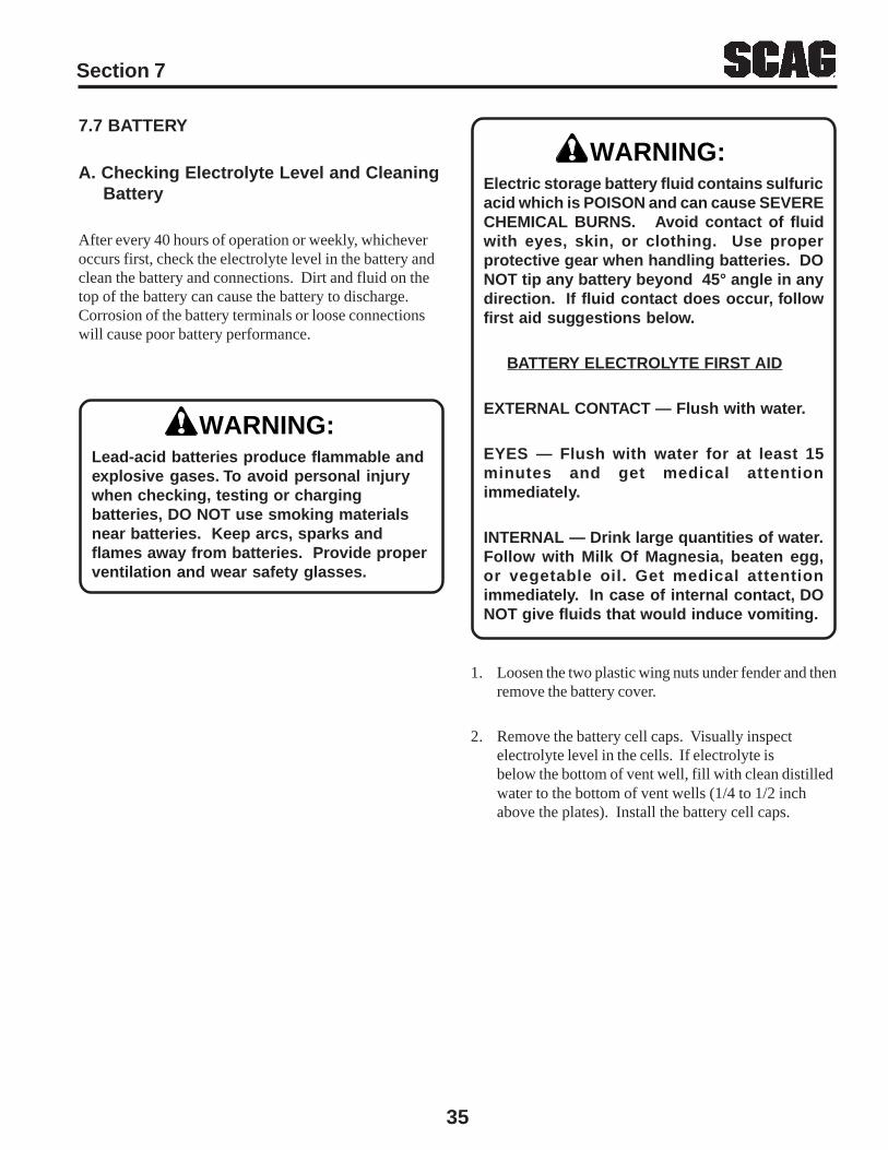
Section 7
35
WARNING:Electric storage battery fluid contains sulfuricacid which is POISON and can cause SEVERECHEMICAL BURNS. Avoid contact of fluidwith eyes, skin, or clothing. Use properprotective gear when handling batteries. DONOT tip any battery beyond 45° angle in anydirection. If fluid contact does occur, followfirst aid suggestions below.
BATTERY ELECTROLYTE FIRST AID
EXTERNAL CONTACT — Flush with water.
EYES — Flush with water for at least 15minutes and get medical attentionimmediately.
INTERNAL — Drink large quantities of water.Follow with Milk Of Magnesia, beaten egg,or vegetable oil. Get medical attentionimmediately. In case of internal contact, DONOT give fluids that would induce vomiting.
1. Loosen the two plastic wing nuts under fender and thenremove the battery cover.
2. Remove the battery cell caps. Visually inspectelectrolyte level in the cells. If electrolyte isbelow the bottom of vent well, fill with clean distilledwater to the bottom of vent wells (1/4 to 1/2 inchabove the plates). Install the battery cell caps.
7.7 BATTERY
A. Checking Electrolyte Level and Cleaning Battery
After every 40 hours of operation or weekly, whicheveroccurs first, check the electrolyte level in the battery andclean the battery and connections. Dirt and fluid on thetop of the battery can cause the battery to discharge.Corrosion of the battery terminals or loose connectionswill cause poor battery performance.
Lead-acid batteries produce flammable andexplosive gases. To avoid personal injurywhen checking, testing or chargingbatteries, DO NOT use smoking materialsnear batteries. Keep arcs, sparks andflames away from batteries. Provide properventilation and wear safety glasses.
WARNING:
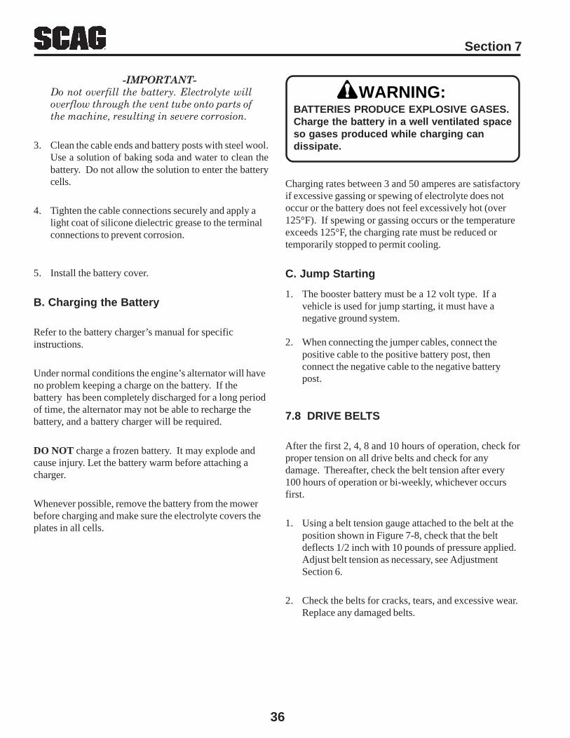
36
Section 7
WARNING:
7.8 DRIVE BELTS
After the first 2, 4, 8 and 10 hours of operation, check forproper tension on all drive belts and check for anydamage. Thereafter, check the belt tension after every100 hours of operation or bi-weekly, whichever occursfirst.
1. Using a belt tension gauge attached to the belt at theposition shown in Figure 7-8, check that the beltdeflects 1/2 inch with 10 pounds of pressure applied.Adjust belt tension as necessary, see AdjustmentSection 6.
2. Check the belts for cracks, tears, and excessive wear.Replace any damaged belts.
-IMPORTANT-Do not overfill the battery. Electrolyte willoverflow through the vent tube onto parts ofthe machine, resulting in severe corrosion.
3. Clean the cable ends and battery posts with steel wool.Use a solution of baking soda and water to clean thebattery. Do not allow the solution to enter the batterycells.
4. Tighten the cable connections securely and apply alight coat of silicone dielectric grease to the terminalconnections to prevent corrosion.
5. Install the battery cover.
B. Charging the Battery
Refer to the battery charger’s manual for specificinstructions.
Under normal conditions the engine’s alternator will haveno problem keeping a charge on the battery. If thebattery has been completely discharged for a long periodof time, the alternator may not be able to recharge thebattery, and a battery charger will be required.
DO NOT charge a frozen battery. It may explode andcause injury. Let the battery warm before attaching acharger.
Whenever possible, remove the battery from the mowerbefore charging and make sure the electrolyte covers theplates in all cells.
BATTERIES PRODUCE EXPLOSIVE GASES.Charge the battery in a well ventilated spaceso gases produced while charging candissipate.
Charging rates between 3 and 50 amperes are satisfactoryif excessive gassing or spewing of electrolyte does notoccur or the battery does not feel excessively hot (over125°F). If spewing or gassing occurs or the temperatureexceeds 125°F, the charging rate must be reduced ortemporarily stopped to permit cooling.
C. Jump Starting
1. The booster battery must be a 12 volt type. If avehicle is used for jump starting, it must have anegative ground system.
2. When connecting the jumper cables, connect thepositive cable to the positive battery post, thenconnect the negative cable to the negative batterypost.

Section 7
37
Gearbox Pulley
Gearbox Pulley
Pump Pulley
CheckTensionHere
CheckTensionHere
CheckTensionHere
TensionIdler Pulley
TensionIdler Pulley
Idler Pulley
Engine Pulley
Electric ClutchPulley
Blower Pulley
Cutter DeckSpindle Pulley
ENGINE DRIVE BELT
TRANSMISSION DRIVE BELT
BLOWER DRIVE BELT
7.9 CUTTER BLADES
A. Blade Inspection
1. Remove the ignition key before servicing the blades.
2. Tilt the mower deck and secure in place with the twoprop rods.
3. Check the blades for straightness by marking the tipposition of the blade on the inside of the deck. Thenrotate the opposite tip of the blade to the sameposition. Compare the difference in the blade tiptrack. If the track is more than 1/8 inch, the blade isbent and should be replaced.
WARNING:
4. If a blade cutting edge is dull or nicked, it should besharpened. Remove the blades for sharpening. See"Blade Replacement."
Do not attempt to straighten a bent blade, andnever weld a broken or cracked blade. Alwaysreplace it with a new blade to assure safety.
Figure 7-8 Belt Tensioning
Never operate the cutter blades with the deckin the raised position because it is hazardous.
WARNING:
(481235)
(481234)
(481237 LH)(481236 RH)
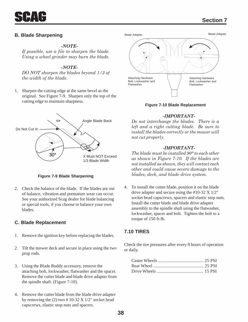
38
Section 7
B. Blade Sharpening
-NOTE-If possible, use a file to sharpen the blade.Using a wheel grinder may burn the blade.
-NOTE-DO NOT sharpen the blades beyond 1/3 ofthe width of the blade.
1. Sharpen the cutting edge at the same bevel as theoriginal. See Figure 7-9. Sharpen only the top of thecutting edge to maintain sharpness.
30°30° X Must NOT Exceed1/3 Blade Width
Angle Blade Back
Do Not Cut In
Figure 7-9 Blade Sharpening
2. Check the balance of the blade. If the blades are outof balance, vibration and premature wear can occur.See your authorized Scag dealer for blade balancingor special tools, if you choose to balance your ownblades.
C. Blade Replacement
1. Remove the ignition key before replacing the blades.
2. Tilt the mower deck and secure in place using the twoprop rods.
3. Using the Blade Buddy accessory, remove theattaching bolt, lockwasher, flatwasher and the spacer.Remove the cutter blade and blade drive adapter fromthe spindle shaft. (Figure 7-10).
4. Remove the cutter blade from the blade drive adapterby removing the (2) two # 10-32 X 1/2" socket headcapscrews, elastic stop nuts and spacers.
Attaching HardwareBolt, Lockwasher andFlatwasher
Attaching HardwareBolt, Lockwasher andFlatwasher
Blade Adapter Blade Adapter
-IMPORTANT-Do not interchange the blades. There is aleft and a right cutting blade. Be sure toinstall the blades correctly or the mower willnot cut properly.
-IMPORTANT-The blade must be installed 90° to each otheras shown in Figure 7-10. If the blades arenot installed as shown, they will contact eachother and could cause severe damage to theblades, deck, and blade drive system.
4. To install the cutter blade, position it on the bladedrive adapter and secure using the #10-32 X 1/2"socket head capscrews, spacers and elastic stop nuts.Install the cutter blade and blade drive adapterassembly to the spindle shaft using the flatwasher,lockwasher, spacer and bolt. Tighten the bolt to atorque of 150 ft-lb.
7.10 TIRES
Check the tire pressures after every 8 hours of operationor daily.
Caster Wheels ......................................... 25 PSIRear Wheel ............................................. 25 PSIDrive Wheels .......................................... 15 PSI
Figure 7-10 Blade Replacement
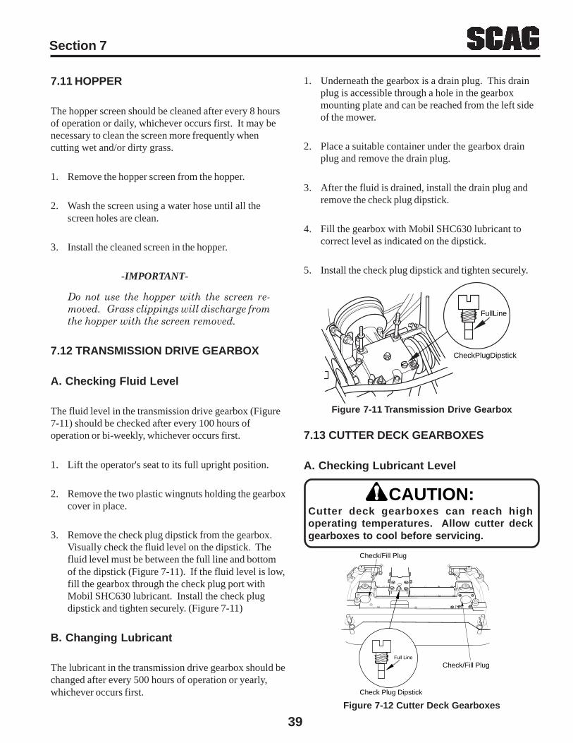
Section 7
39
CheckPlugDipstick
FullLine
1. Underneath the gearbox is a drain plug. This drainplug is accessible through a hole in the gearboxmounting plate and can be reached from the left sideof the mower.
2. Place a suitable container under the gearbox drainplug and remove the drain plug.
3. After the fluid is drained, install the drain plug andremove the check plug dipstick.
4. Fill the gearbox with Mobil SHC630 lubricant tocorrect level as indicated on the dipstick.
5. Install the check plug dipstick and tighten securely.
7.11 HOPPER
The hopper screen should be cleaned after every 8 hoursof operation or daily, whichever occurs first. It may benecessary to clean the screen more frequently whencutting wet and/or dirty grass.
1. Remove the hopper screen from the hopper.
2. Wash the screen using a water hose until all thescreen holes are clean.
3. Install the cleaned screen in the hopper.
-IMPORTANT-
Do not use the hopper with the screen re-moved. Grass clippings will discharge fromthe hopper with the screen removed.
7.12 TRANSMISSION DRIVE GEARBOX
A. Checking Fluid Level
The fluid level in the transmission drive gearbox (Figure7-11) should be checked after every 100 hours ofoperation or bi-weekly, whichever occurs first.
1. Lift the operator's seat to its full upright position.
2. Remove the two plastic wingnuts holding the gearboxcover in place.
3. Remove the check plug dipstick from the gearbox.Visually check the fluid level on the dipstick. Thefluid level must be between the full line and bottomof the dipstick (Figure 7-11). If the fluid level is low,fill the gearbox through the check plug port withMobil SHC630 lubricant. Install the check plugdipstick and tighten securely. (Figure 7-11)
B. Changing Lubricant
The lubricant in the transmission drive gearbox should bechanged after every 500 hours of operation or yearly,whichever occurs first.
Figure 7-12 Cutter Deck GearboxesCheck Plug Dipstick
Check/Fill Plug
Check/Fill PlugFull Line
Cutter deck gearboxes can reach highoperating temperatures. Allow cutter deckgearboxes to cool before servicing.
CAUTION:
7.13 CUTTER DECK GEARBOXES
A. Checking Lubricant Level
Figure 7-11 Transmission Drive Gearbox
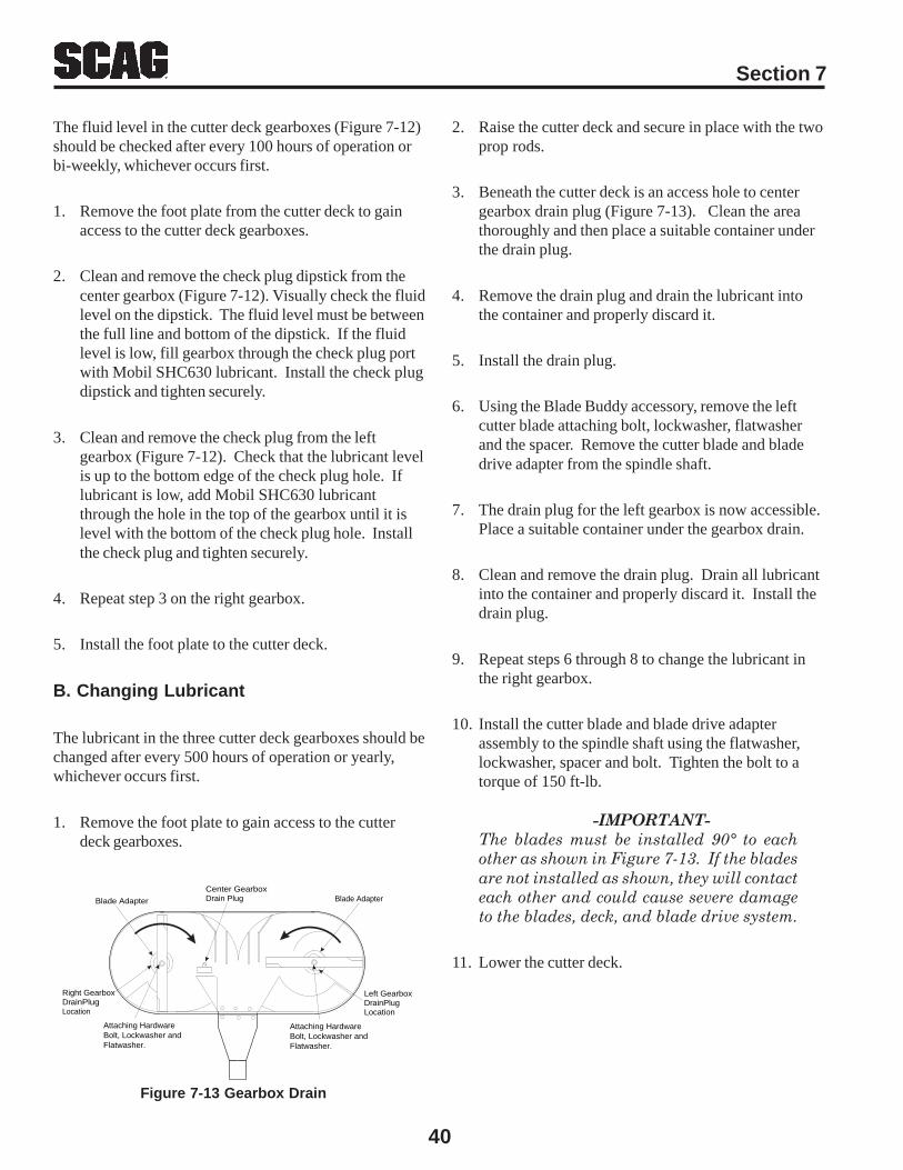
40
Section 7
The fluid level in the cutter deck gearboxes (Figure 7-12)should be checked after every 100 hours of operation orbi-weekly, whichever occurs first.
1. Remove the foot plate from the cutter deck to gainaccess to the cutter deck gearboxes.
2. Clean and remove the check plug dipstick from thecenter gearbox (Figure 7-12). Visually check the fluidlevel on the dipstick. The fluid level must be betweenthe full line and bottom of the dipstick. If the fluidlevel is low, fill gearbox through the check plug portwith Mobil SHC630 lubricant. Install the check plugdipstick and tighten securely.
3. Clean and remove the check plug from the leftgearbox (Figure 7-12). Check that the lubricant levelis up to the bottom edge of the check plug hole. Iflubricant is low, add Mobil SHC630 lubricantthrough the hole in the top of the gearbox until it islevel with the bottom of the check plug hole. Installthe check plug and tighten securely.
4. Repeat step 3 on the right gearbox.
5. Install the foot plate to the cutter deck.
B. Changing Lubricant
The lubricant in the three cutter deck gearboxes should bechanged after every 500 hours of operation or yearly,whichever occurs first.
1. Remove the foot plate to gain access to the cutterdeck gearboxes.
2. Raise the cutter deck and secure in place with the twoprop rods.
3. Beneath the cutter deck is an access hole to centergearbox drain plug (Figure 7-13). Clean the areathoroughly and then place a suitable container underthe drain plug.
4. Remove the drain plug and drain the lubricant intothe container and properly discard it.
5. Install the drain plug.
6. Using the Blade Buddy accessory, remove the leftcutter blade attaching bolt, lockwasher, flatwasherand the spacer. Remove the cutter blade and bladedrive adapter from the spindle shaft.
7. The drain plug for the left gearbox is now accessible.Place a suitable container under the gearbox drain.
8. Clean and remove the drain plug. Drain all lubricantinto the container and properly discard it. Install thedrain plug.
9. Repeat steps 6 through 8 to change the lubricant inthe right gearbox.
10. Install the cutter blade and blade drive adapterassembly to the spindle shaft using the flatwasher,lockwasher, spacer and bolt. Tighten the bolt to atorque of 150 ft-lb.
-IMPORTANT-The blades must be installed 90° to eachother as shown in Figure 7-13. If the bladesare not installed as shown, they will contacteach other and could cause severe damageto the blades, deck, and blade drive system.
11. Lower the cutter deck.
Figure 7-13 Gearbox Drain
Blade Adapter
Center GearboxDrain Plug
Left Gearbox DrainPlugLocation
Right Gearbox DrainPlugLocation
Blade Adapter
Attaching HardwareBolt, Lockwasher andFlatwasher.
Attaching HardwareBolt, Lockwasher andFlatwasher.
Section 7
41
12. Clean and remove the check plug dipstick from thecenter gearbox and fill the gearbox with MobilSHC630 lubricant until it is full, as indicated on thedipstick. Install the check plug dipstick and tightensecurely, then back the dipstick out so that the slot isparallel with the front of the gearbox.
13. Clean and remove the check plug from the leftgearbox. Fill the gearbox with Mobil SHC630lubricant through the check plug hole until it starts toexit the hole. Install the check plug and tightensecurely.
14. Repeat step 13 on the right gearbox.
15. Clean the three breathers with a non-flammablesolvent.
16. Install the foot plate to the cutter deck.
Do not wash any portion of the equipmentwhile it is hot. Do not wash the engine; usecompressed air.
CAUTION:
1. After each use, wash the mower, deck and hopper.Use cold water and automotive cleaners. Do not usepressure cleaners.
2. Do not spray electrical components.
3. Use a mild soap solution or a vinyl/rubber cleaner toclean the seat.
4. Repair damaged metal surfaces and use Scag touch-up paint available from your authorized Scag dealer.Wax or polish the mower for maximum paintprotection.
7.14 BODY, DECK, HOPPER AND UPHOLSTERY
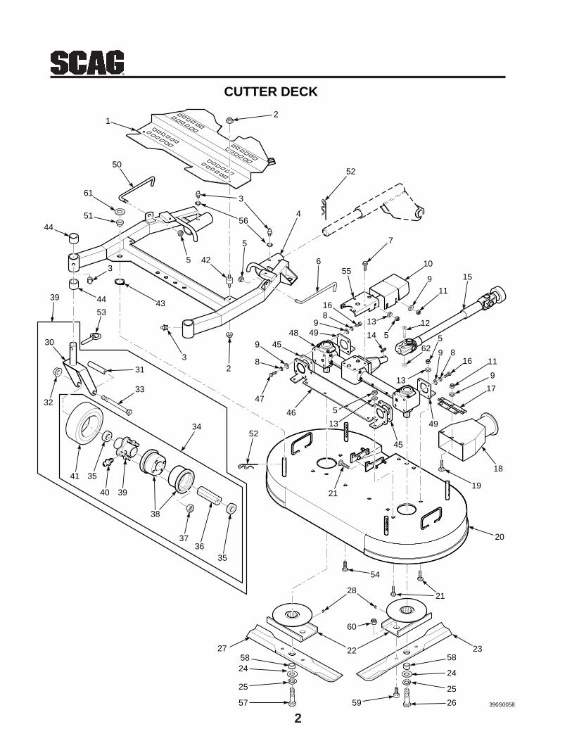
2
13
12
3
4
5
5
52
7
10
911
15
13
51412
5
13
816 11
9
17
18
49
19
21
20
23
24
25
57
28
52
21
3536
37
38
3940
3541
33
31
32
30
34
39
53
44 43
32
63
4451
61
50
47
8
489
816
45
46 5
4255
54
22
49
CUTTER DECK
56
24
25
26
99
45
59
58
60
390S0058
5827
62
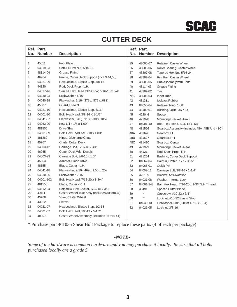
3
Ref. Part.No. Number Description
35 48006-07 Retainer, Caster Wheel
36 48006-06 Roller Bearing, Caster Wheel
37 48307-08 Tapered Hex Nut, 5/16-24
38 48307-04 Rim Pair, Caster Wheel
39 48006-05 Hub Assembly with Bolts
40 48114-03 Grease Fitting
41 48307-02 Tire
N/S 48006-03 Inner Tube
42 481311 Isolator, Rubber
43 04050-04 Retainer Ring, 1.00"
44 48100-01 Bushing, Oilite, .877 ID
45 422046 Spacer
46 421928 Mounting Bracket - Front
47 04001-10 Bolt, Hex Head, 5/16-18 1-1/4"
48 481596 Gearbox Assembly (Includes 48A ,48B And 48C)
48A 481626 Gearbox, LH
48B 481627 Gearbox, RH
48C 481410 Gearbox, Center
49 421929 Mounting Bracket - Rear
50 44121 Rod, Deck Prop - R.H.
51 481264 Bushing, Cutter Deck Support
52 04062-04 Hairpin, Cotter, .177 x 3.25"
53 04066-01 Quick Pin
54 04003-11 Carriage Bolt, 3/8-16 x 1-1/4"
55 422109 Bracket, Anti-Rotation
56 04031-08 Washer, Internal Lock
57 04001-143 Bolt, Hex Head, 7/16-20 x 1-3/4" LH Thread
58 43491 Spacer, Cutter Blade
59 * Capscrew, #10-32 x 3/4"
60 * Locknut, #10-32 Elastic Stop
61 04040-10 Flatwasher, 5/8" (.688 x 1.750 x .134)
62 04021-05 Locknut, 3/8-16
CUTTER DECKRef. Part.No. Number Description
1 45811 Foot Plate
2 04019-03 Serr. Fl. Hex Nut, 5/16-18
3 48114-04 Grease Fitting
4 46964 Frame, Cutter Deck Support (incl. 3,44,56)
5 04021-09 Hex Locknut, Elastic Stop, 3/8-16
6 44120 Rod, Deck Prop - L.H.
7 04017-16 Serr. Fl. Hex Head CPSCRW, 5/16-18 x 3/4"
8 04030-03 Lockwasher, 5/16"
9 04040-15 Flatwasher, 5/16 (.375 x .875 x .083)
10 45887 Guard, U-Joint
11 04021-10 Hex Locknut, Elastic Stop, 5/16"
12 04001-20 Bolt, Hex Head, 3/8-16 X 1-1/2"
13 04041-07 Flatwasher, 3/8 (.391 x .938 x .105)
14 04063-20 Key, 1/4 x 1/4 x 1.00"
15 481505 Drive Shaft
16 04001-09 Bolt, Hex Head, 5/16-18 x 1.00"
17 481262 Hinge, Discharge Chute
18 45767 Chute, Cutter Deck
19 04003-12 Carriage Bolt, 5/16-18 x 3/4"
20 46965 Cutter Deck With Decals
21 04003-23 Carriage Bolt, 3/8-16 x 1.0"
22 45863 Adapter, Blade Drive
23 481554 Blade, Cutter - L.H.
24 04041-18 Flatwasher, 7/16 (.469 x 1.50 x .25)
25 04030-05 Lockwasher, 7/16"
26 04001-102 Bolt, Hex Head, 7/16-20 x 1-3/4"
27 481555 Blade, Cutter - R.H.
28 04012-04 Setscrew, Hex Socket, 5/16-18 x 3/8"29 49111 Caster Wheel Yoke Assy (Includes 30 thru34)30 45768 Yoke, Caster Wheel
31 43022 Sleeve
32 04021-07 Hex Locknut, Elastic Stop, 1/2-13
33 04001-37 Bolt, Hex Head, 1/2-13 x 5-1/2"
34 48307 Caster Wheel Assembly (Includes 35 thru 41)
-NOTE-
Some of the hardware is common hardware and you may purchase it locally. Be sure that all boltspurchased locally are a grade 5.
* Purchase part 461035 Shear Bolt Package to replace these parts. (4 of each per package)

4
6849
13
17
817
1
2
3
4
56
7
89
8 10
13
11
12
13 126
15
14
1619
2120
22
24
2520
16
82
88 8939
83
12
16
24
23
32
31
7
29
28
6
16
6726
67
16
96
16
12
26
76
94
4137
39
40
38
43
7
6
42
3845
44
46
47
7 48
39
A
57
49
5152
5354
5556
50
7
6
15
665
66
390S005916
48
74748
7
58
59
58
61
63
64
33
35
A67
47
48
7
58
39
59
47 48
7
69
7035
71
34
7242
74 7313
753
90
92
13
35
40
917678
77
85
84
79
86
87
104
27
81
13
SHEET METAL
18
40
80
23
9320
32
30
95
97
1423
23
10098
99
60
1262
34
24
7
36
103
101102
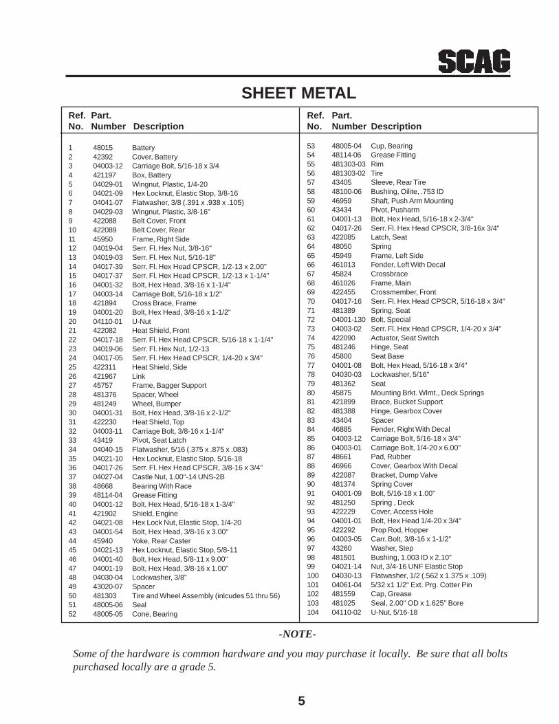
5
Ref. Part.No. Number Description
1 48015 Battery2 42392 Cover, Battery3 04003-12 Carriage Bolt, 5/16-18 x 3/44 421197 Box, Battery5 04029-01 Wingnut, Plastic, 1/4-206 04021-09 Hex Locknut, Elastic Stop, 3/8-167 04041-07 Flatwasher, 3/8 (.391 x .938 x .105)8 04029-03 Wingnut, Plastic, 3/8-16"9 422088 Belt Cover, Front10 422089 Belt Cover, Rear11 45950 Frame, Right Side12 04019-04 Serr. Fl. Hex Nut, 3/8-16"13 04019-03 Serr. Fl. Hex Nut, 5/16-18"14 04017-39 Serr. Fl. Hex Head CPSCR, 1/2-13 x 2.00"15 04017-37 Serr. Fl. Hex Head CPSCR, 1/2-13 x 1-1/4"16 04001-32 Bolt, Hex Head, 3/8-16 x 1-1/4"17 04003-14 Carriage Bolt, 5/16-18 x 1/2"18 421894 Cross Brace, Frame19 04001-20 Bolt, Hex Head, 3/8-16 x 1-1/2"20 04110-01 U-Nut21 422082 Heat Shield, Front22 04017-18 Serr. Fl. Hex Head CPSCR, 5/16-18 x 1-1/4"23 04019-06 Serr. Fl. Hex Nut, 1/2-1324 04017-05 Serr. Fl. Hex Head CPSCR, 1/4-20 x 3/4"25 422311 Heat Shield, Side26 421967 Link27 45757 Frame, Bagger Support28 481376 Spacer, Wheel29 481249 Wheel, Bumper30 04001-31 Bolt, Hex Head, 3/8-16 x 2-1/2"31 422230 Heat Shield, Top32 04003-11 Carriage Bolt, 3/8-16 x 1-1/4"33 43419 Pivot, Seat Latch34 04040-15 Flatwasher, 5/16 (.375 x .875 x .083)35 04021-10 Hex Locknut, Elastic Stop, 5/16-1836 04017-26 Serr. Fl. Hex Head CPSCR, 3/8-16 x 3/4"37 04027-04 Castle Nut, 1.00"-14 UNS-2B38 48668 Bearing With Race39 48114-04 Grease Fitting40 04001-12 Bolt, Hex Head, 5/16-18 x 1-3/4"41 421902 Shield, Engine42 04021-08 Hex Lock Nut, Elastic Stop, 1/4-2043 04001-54 Bolt, Hex Head, 3/8-16 x 3.00"44 45940 Yoke, Rear Caster45 04021-13 Hex Locknut, Elastic Stop, 5/8-1146 04001-40 Bolt, Hex Head, 5/8-11 x 9.00"47 04001-19 Bolt, Hex Head, 3/8-16 x 1.00"48 04030-04 Lockwasher, 3/8"49 43020-07 Spacer50 481303 Tire and Wheel Assembly (inlcudes 51 thru 56)51 48005-06 Seal52 48005-05 Cone, Bearing
SHEET METALRef. Part.No. Number Description
53 48005-04 Cup, Bearing54 48114-06 Grease Fitting55 481303-03 Rim56 481303-02 Tire57 43405 Sleeve, Rear Tire58 48100-06 Bushing, Oilite, .753 ID59 46959 Shaft, Push Arm Mounting60 43434 Pivot, Pusharm61 04001-13 Bolt, Hex Head, 5/16-18 x 2-3/4"62 04017-26 Serr. Fl. Hex Head CPSCR, 3/8-16x 3/4"63 422085 Latch, Seat64 48050 Spring65 45949 Frame, Left Side66 461013 Fender, Left With Decal67 45824 Crossbrace68 461026 Frame, Main69 422455 Crossmember, Front70 04017-16 Serr. Fl. Hex Head CPSCR, 5/16-18 x 3/4"71 481389 Spring, Seat72 04001-130 Bolt, Special73 04003-02 Serr. Fl. Hex Head CPSCR, 1/4-20 x 3/4"74 422090 Actuator, Seat Switch75 481246 Hinge, Seat76 45800 Seat Base77 04001-08 Bolt, Hex Head, 5/16-18 x 3/4"78 04030-03 Lockwasher, 5/16"79 481362 Seat80 45875 Mounting Brkt. Wlmt., Deck Springs81 421899 Brace, Bucket Support82 481388 Hinge, Gearbox Cover83 43404 Spacer84 46885 Fender, Right With Decal85 04003-12 Carriage Bolt, 5/16-18 x 3/4"86 04003-01 Carriage Bolt, 1/4-20 x 6.00"87 48661 Pad, Rubber88 46966 Cover, Gearbox With Decal89 422087 Bracket, Dump Valve90 481374 Spring Cover91 04001-09 Bolt, 5/16-18 x 1.00"92 481250 Spring , Deck93 422229 Cover, Access Hole94 04001-01 Bolt, Hex Head 1/4-20 x 3/4"95 422292 Prop Rod, Hopper96 04003-05 Carr. Bolt, 3/8-16 x 1-1/2"97 43260 Washer, Step98 481501 Bushing, 1.003 ID x 2.10"99 04021-14 Nut, 3/4-16 UNF Elastic Stop100 04030-13 Flatwasher, 1/2 (.562 x 1.375 x .109)101 04061-04 5/32 x1 1/2" Ext. Prg. Cotter Pin102 481559 Cap, Grease103 481025 Seal, 2.00" OD x 1.625" Bore104 04110-02 U-Nut, 5/16-18
Some of the hardware is common hardware and you may purchase it locally. Be sure that all boltspurchased locally are a grade 5.
-NOTE-

6
49
44
34
44
1
2
3
4
56
3
49
3
49
7
3
8
15
10
48
4746
45
42
12
40
39
3837
36
13
51
50
4414
35
28
3332 31
3029
2827
26
24
22
30
3216
23
21
20
17
183
19
BLOWER ASSEMBLY
14
43
41
23 25
52
53
9 11
54
390S0060
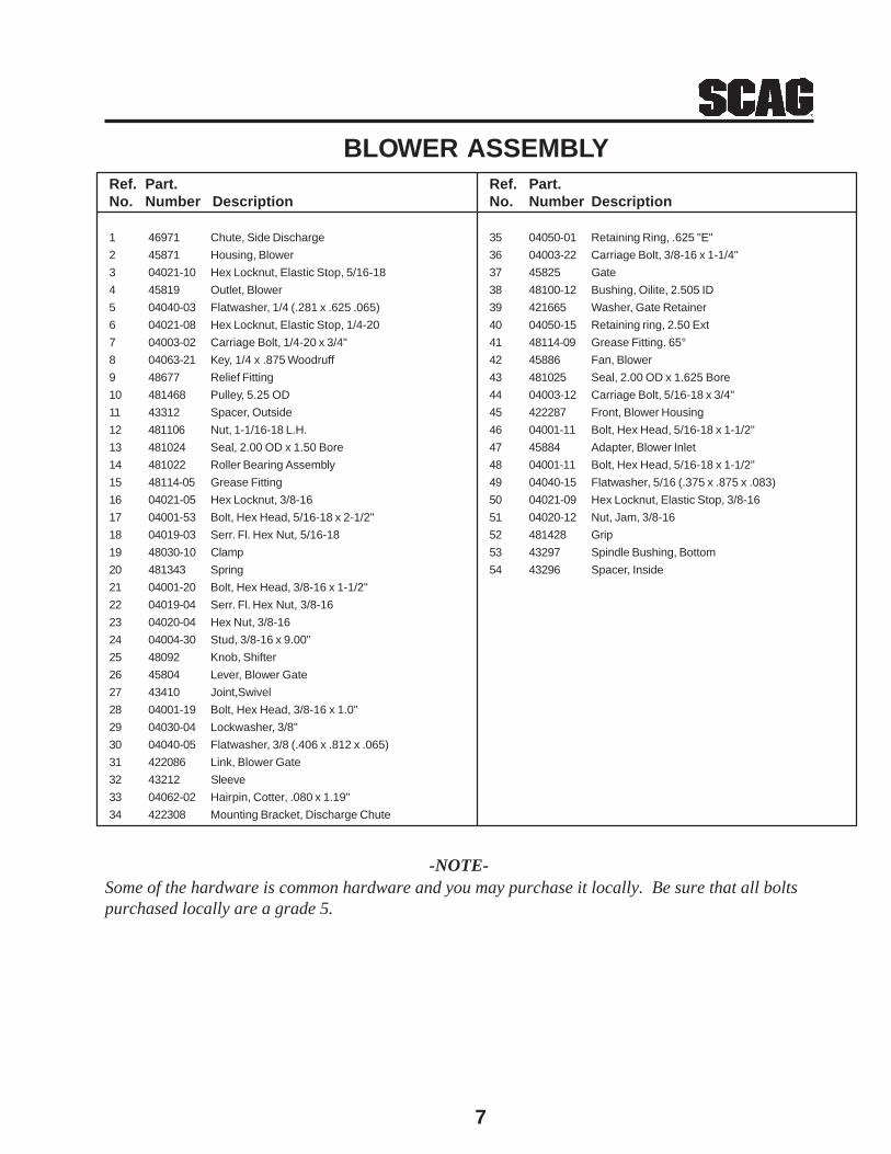
7
Ref. Part.No. Number Description
35 04050-01 Retaining Ring, .625 "E"
36 04003-22 Carriage Bolt, 3/8-16 x 1-1/4"
37 45825 Gate
38 48100-12 Bushing, Oilite, 2.505 ID
39 421665 Washer, Gate Retainer
40 04050-15 Retaining ring, 2.50 Ext
41 48114-09 Grease Fitting. 65°
42 45886 Fan, Blower
43 481025 Seal, 2.00 OD x 1.625 Bore
44 04003-12 Carriage Bolt, 5/16-18 x 3/4"
45 422287 Front, Blower Housing
46 04001-11 Bolt, Hex Head, 5/16-18 x 1-1/2"
47 45884 Adapter, Blower Inlet
48 04001-11 Bolt, Hex Head, 5/16-18 x 1-1/2"
49 04040-15 Flatwasher, 5/16 (.375 x .875 x .083)
50 04021-09 Hex Locknut, Elastic Stop, 3/8-16
51 04020-12 Nut, Jam, 3/8-16
52 481428 Grip
53 43297 Spindle Bushing, Bottom
54 43296 Spacer, Inside
Ref. Part.No. Number Description
1 46971 Chute, Side Discharge
2 45871 Housing, Blower
3 04021-10 Hex Locknut, Elastic Stop, 5/16-18
4 45819 Outlet, Blower
5 04040-03 Flatwasher, 1/4 (.281 x .625 .065)
6 04021-08 Hex Locknut, Elastic Stop, 1/4-20
7 04003-02 Carriage Bolt, 1/4-20 x 3/4"
8 04063-21 Key, 1/4 x .875 Woodruff
9 48677 Relief Fitting
10 481468 Pulley, 5.25 OD
11 43312 Spacer, Outside
12 481106 Nut, 1-1/16-18 L.H.
13 481024 Seal, 2.00 OD x 1.50 Bore
14 481022 Roller Bearing Assembly
15 48114-05 Grease Fitting
16 04021-05 Hex Locknut, 3/8-16
17 04001-53 Bolt, Hex Head, 5/16-18 x 2-1/2"
18 04019-03 Serr. Fl. Hex Nut, 5/16-18
19 48030-10 Clamp
20 481343 Spring
21 04001-20 Bolt, Hex Head, 3/8-16 x 1-1/2"
22 04019-04 Serr. Fl. Hex Nut, 3/8-16
23 04020-04 Hex Nut, 3/8-16
24 04004-30 Stud, 3/8-16 x 9.00"
25 48092 Knob, Shifter
26 45804 Lever, Blower Gate
27 43410 Joint,Swivel
28 04001-19 Bolt, Hex Head, 3/8-16 x 1.0"
29 04030-04 Lockwasher, 3/8"
30 04040-05 Flatwasher, 3/8 (.406 x .812 x .065)
31 422086 Link, Blower Gate
32 43212 Sleeve
33 04062-02 Hairpin, Cotter, .080 x 1.19"
34 422308 Mounting Bracket, Discharge Chute
BLOWER ASSEMBLY
-NOTE-Some of the hardware is common hardware and you may purchase it locally. Be sure that all boltspurchased locally are a grade 5.
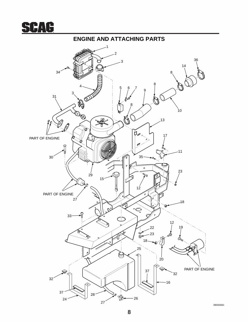
8
1
2
3
4 5 6
313
8
9
8
10
13
30
29
27
15
PART OF ENGINE
PART OF ENGINE
PART OF ENGINE
12
18
22
23
1219
18
20
2627
28
16
25
32
33
32
34
ENGINE AND ATTACHING PARTS
8
14
390S0061
23
11
7
36
35
17
24
37
37
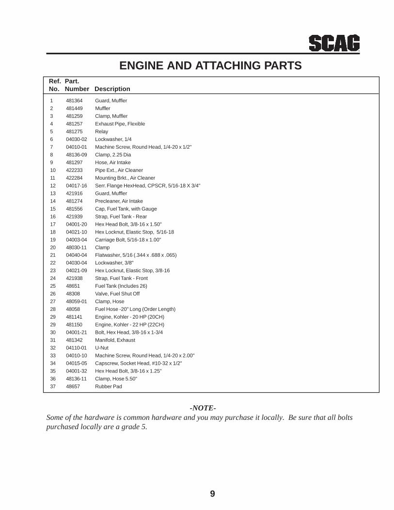
9
1 481364 Guard, Muffler
2 481449 Muffler
3 481259 Clamp, Muffler
4 481257 Exhaust Pipe, Flexible
5 481275 Relay
6 04030-02 Lockwasher, 1/4
7 04010-01 Machine Screw, Round Head, 1/4-20 x 1/2"
8 48136-09 Clamp, 2.25 Dia
9 481297 Hose, Air Intake
10 422233 Pipe Ext., Air Cleaner
11 422284 Mounting Brkt., Air Cleaner
12 04017-16 Serr. Flange HexHead, CPSCR, 5/16-18 X 3/4"
13 421916 Guard, Muffler
14 481274 Precleaner, Air Intake
15 481556 Cap, Fuel Tank, with Gauge
16 421939 Strap, Fuel Tank - Rear
17 04001-20 Hex Head Bolt, 3/8-16 x 1.50"
18 04021-10 Hex Locknut, Elastic Stop, 5/16-18
19 04003-04 Carriage Bolt, 5/16-18 x 1.00"
20 48030-11 Clamp
21 04040-04 Flatwasher, 5/16 (.344 x .688 x .065)
22 04030-04 Lockwasher, 3/8"
23 04021-09 Hex Locknut, Elastic Stop, 3/8-16
24 421938 Strap, Fuel Tank - Front
25 48651 Fuel Tank (Includes 26)
26 48308 Valve, Fuel Shut Off
27 48059-01 Clamp, Hose
28 48058 Fuel Hose -20" Long (Order Length)
29 481141 Engine, Kohler - 20 HP (20CH)
29 481150 Engine, Kohler - 22 HP (22CH)
30 04001-21 Bolt, Hex Head, 3/8-16 x 1-3/4
31 481342 Manifold, Exhaust
32 04110-01 U-Nut
33 04010-10 Machine Screw, Round Head, 1/4-20 x 2.00"
34 04015-05 Capscrew, Socket Head, #10-32 x 1/2"
35 04001-32 Hex Head Bolt, 3/8-16 x 1.25"
36 48136-11 Clamp, Hose 5.50"
37 48657 Rubber Pad
Ref. Part.No. Number Description
ENGINE AND ATTACHING PARTS
-NOTE-Some of the hardware is common hardware and you may purchase it locally. Be sure that all boltspurchased locally are a grade 5.
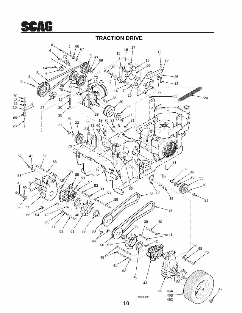
10
12
364
4
5
6
70
867 17
19 23
2
25
28
2830
27
1
21
2670
12
20
25
27
21
7033
31 60
19
29
70 21
66
35
31
32
36
37
3839 40
41
4262
45
4744
43
48
53
41
49
5150
38
48
5241
53
425466
62
53
57 52
53
58
5357
5339
53
59
63
TRACTION DRIVE
70
65
55
45
50
64
61
56
41
35
34
65
7 68
967
68
15
22
16
70
390S0062
46A46B46C
7219 71
22
18
7
11
14 7
12
25
13
12
122510
69
20
70
34
33
70
21
70
73
73
70
32
24
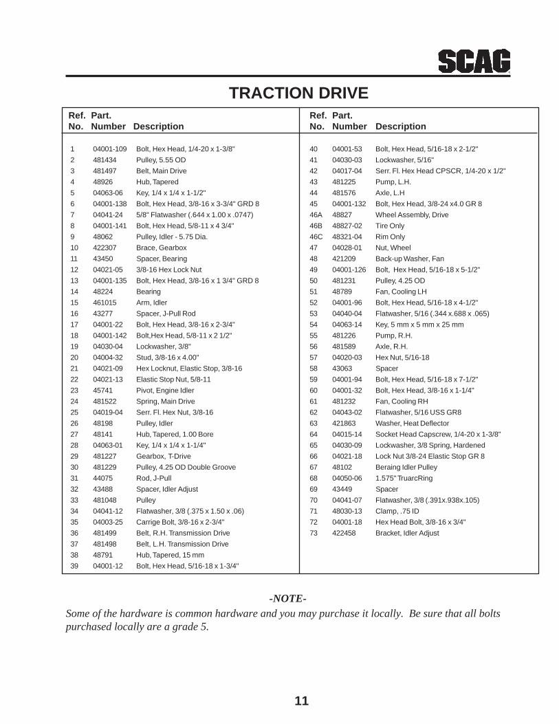
11
Ref. Part.No. Number Description
40 04001-53 Bolt, Hex Head, 5/16-18 x 2-1/2"
41 04030-03 Lockwasher, 5/16"
42 04017-04 Serr. Fl. Hex Head CPSCR, 1/4-20 x 1/2"
43 481225 Pump, L.H.
44 481576 Axle, L.H
45 04001-132 Bolt, Hex Head, 3/8-24 x4.0 GR 8
46A 48827 Wheel Assembly, Drive
46B 48827-02 Tire Only
46C 48321-04 Rim Only
47 04028-01 Nut, Wheel
48 421209 Back-up Washer, Fan
49 04001-126 Bolt, Hex Head, 5/16-18 x 5-1/2"
50 481231 Pulley, 4.25 OD
51 48789 Fan, Cooling LH
52 04001-96 Bolt, Hex Head, 5/16-18 x 4-1/2"
53 04040-04 Flatwasher, 5/16 (.344 x.688 x .065)
54 04063-14 Key, 5 mm x 5 mm x 25 mm
55 481226 Pump, R.H.
56 481589 Axle, R.H.
57 04020-03 Hex Nut, 5/16-18
58 43063 Spacer
59 04001-94 Bolt, Hex Head, 5/16-18 x 7-1/2"
60 04001-32 Bolt, Hex Head, 3/8-16 x 1-1/4"
61 481232 Fan, Cooling RH
62 04043-02 Flatwasher, 5/16 USS GR8
63 421863 Washer, Heat Deflector
64 04015-14 Socket Head Capscrew, 1/4-20 x 1-3/8"
65 04030-09 Lockwasher, 3/8 Spring, Hardened
66 04021-18 Lock Nut 3/8-24 Elastic Stop GR 8
67 48102 Beraing Idler Pulley
68 04050-06 1.575" TruarcRing
69 43449 Spacer
70 04041-07 Flatwasher, 3/8 (.391x.938x.105)
71 48030-13 Clamp, .75 ID
72 04001-18 Hex Head Bolt, 3/8-16 x 3/4"
73 422458 Bracket, Idler Adjust
Ref. Part.No. Number Description
1 04001-109 Bolt, Hex Head, 1/4-20 x 1-3/8"
2 481434 Pulley, 5.55 OD
3 481497 Belt, Main Drive
4 48926 Hub, Tapered
5 04063-06 Key, 1/4 x 1/4 x 1-1/2"
6 04001-138 Bolt, Hex Head, 3/8-16 x 3-3/4" GRD 8
7 04041-24 5/8" Flatwasher (.644 x 1.00 x .0747)
8 04001-141 Bolt, Hex Head, 5/8-11 x 4 3/4"
9 48062 Pulley, Idler - 5.75 Dia.
10 422307 Brace, Gearbox
11 43450 Spacer, Bearing
12 04021-05 3/8-16 Hex Lock Nut
13 04001-135 Bolt, Hex Head, 3/8-16 x 1 3/4" GRD 8
14 48224 Bearing
15 461015 Arm, Idler
16 43277 Spacer, J-Pull Rod
17 04001-22 Bolt, Hex Head, 3/8-16 x 2-3/4"
18 04001-142 Bolt,Hex Head, 5/8-11 x 2 1/2"
19 04030-04 Lockwasher, 3/8"
20 04004-32 Stud, 3/8-16 x 4.00"
21 04021-09 Hex Locknut, Elastic Stop, 3/8-16
22 04021-13 Elastic Stop Nut, 5/8-11
23 45741 Pivot, Engine Idler
24 481522 Spring, Main Drive
25 04019-04 Serr. Fl. Hex Nut, 3/8-16
26 48198 Pulley, Idler
27 48141 Hub, Tapered, 1.00 Bore
28 04063-01 Key, 1/4 x 1/4 x 1-1/4"
29 481227 Gearbox, T-Drive
30 481229 Pulley, 4.25 OD Double Groove
31 44075 Rod, J-Pull
32 43488 Spacer, Idler Adjust
33 481048 Pulley
34 04041-12 Flatwasher, 3/8 (.375 x 1.50 x .06)
35 04003-25 Carrige Bolt, 3/8-16 x 2-3/4"
36 481499 Belt, R.H. Transmission Drive
37 481498 Belt, L.H. Transmission Drive
38 48791 Hub, Tapered, 15 mm
39 04001-12 Bolt, Hex Head, 5/16-18 x 1-3/4"
TRACTION DRIVE
-NOTE-Some of the hardware is common hardware and you may purchase it locally. Be sure that all boltspurchased locally are a grade 5.
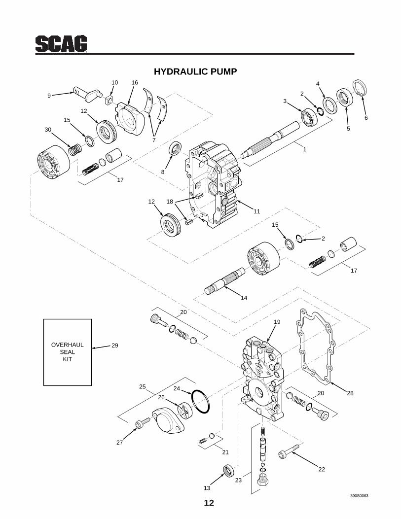
12
HYDRAULIC PUMP
390S0063
22
17
20
2313
21
25
27
26
2428
17
14
15
2
12
30
15
3
5
6
2
4
11
8
12
9
10
7
16
18
20
1
29OVERHAULSEALKIT
19
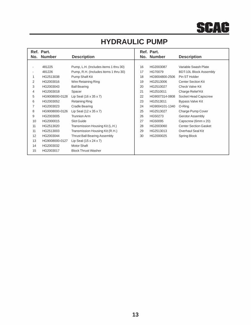
13
Ref. Part.No. Number Description
- 481225 Pump, L.H. (Includes items 1 thru 30)
- 481226 Pump, R.H. (Includes items 1 thru 30)
1 HG2513038 Pump Shaft Kit
2 HG2003016 Wire Retaining Ring
3 HG2003043 Ball Bearing
4 HG2003018 Spacer
5 HG9008000-0128 Lip Seal (16 x 35 x 7)
6 HG2003052 Retaining Ring
7 HG2003023 Cradle Bearing
8 HG9008000-0126 Lip Seal (12 x 35 x 7)
9 HG2003005 Trunnion Arm
10 HG2000015 Slot Guide
11 HG2513020 Transmission Housing Kit (L.H.)
11 HG2513003 Transmission Housing Kit (R.H.)
12 HG2003044 Thrust Ball Bearing Assembly
13 HG9008000-0127 Lip Seal (15 x 24 x 7)
14 HG2003032 Motor Shaft
15 HG2003017 Block Thrust Washer
Ref. Part.No. Number Description
16 HG2003087 Variable Swash Plate
17 HG70079 BDT-10L Block Assembly
18 HG9004800-2506 Pin ST Holder
19 HG2513006 Center Section Kit
20 HG2510027 Check Valve Kit
21 HG2510011 Charge Relief Kit
22 HG9007314-0808 Socket Head Capscrew
23 HG2513011 Bypass Valve Kit
24 HG9004101-1340 O-Ring
25 HG2513027 Charge Pump Cover
26 HG50273 Gerotor Assembly
27 HG50095 Capscrew (6mm x 20)
28 HG2003060 Center Section Gasket
29 HG2513013 Overhaul Seal Kit
30 HG2000025 Spring Block
HYDRAULIC PUMP
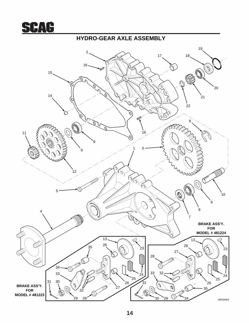
14
HYDRO-GEAR AXLE ASSEMBLY
390S0064
11
9
8
15
18
19
22
21
20
6
16
31
12
2
7
8
9
105
4
17
16
14
31
2635
30
33
34
29 28
3227
2625
24
13
23
2524
26
35
342930
31
3233
2827
26
13
23
BRAKE ASS'Y.FOR
MODEL # 481223
BRAKE ASS'Y.FOR
MODEL # 481224
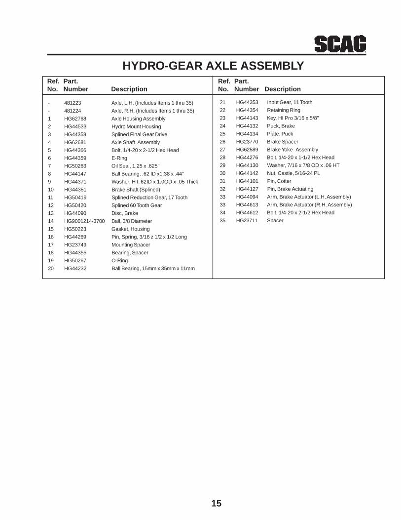
15
HYDRO-GEAR AXLE ASSEMBLY
- 481223 Axle, L.H. (Includes Items 1 thru 35)
- 481224 Axle, R.H. (Includes Items 1 thru 35)
1 HG62768 Axle Housing Assembly
2 HG44533 Hydro Mount Housing
3 HG44358 Splined Final Gear Drive
4 HG62681 Axle Shaft Assembly
5 HG44366 Bolt, 1/4-20 x 2-1/2 Hex Head
6 HG44359 E-Ring
7 HG50263 Oil Seal, 1.25 x .625"
8 HG44147 Ball Bearing, .62 ID x1.38 x .44"
9 HG44371 Washer, HT. 62ID x 1.0OD x .05 Thick
10 HG44351 Brake Shaft (Splined)
11 HG50419 Splined Reduction Gear, 17 Tooth
12 HG50420 Splined 60 Tooth Gear
13 HG44090 Disc, Brake
14 HG9001214-3700 Ball, 3/8 Diameter
15 HG50223 Gasket, Housing
16 HG44269 Pin, Spring, 3/16 z 1/2 x 1/2 Long
17 HG23749 Mounting Spacer
18 HG44355 Bearing, Spacer
19 HG50267 O-Ring
20 HG44232 Ball Bearing, 15mm x 35mm x 11mm
Ref. Part.No. Number Description
21 HG44353 Input Gear, 11 Tooth
22 HG44354 Retaining Ring
23 HG44143 Key, HI Pro 3/16 x 5/8"
24 HG44132 Puck, Brake
25 HG44134 Plate, Puck
26 HG23770 Brake Spacer
27 HG62589 Brake Yoke Assembly
28 HG44276 Bolt, 1/4-20 x 1-1/2 Hex Head
29 HG44130 Washer, 7/16 x 7/8 OD x .06 HT
30 HG44142 Nut, Castle, 5/16-24 PL
31 HG44101 Pin, Cotter
32 HG44127 Pin, Brake Actuating
33 HG44094 Arm, Brake Actuator (L.H. Assembly)
33 HG44613 Arm, Brake Actuator (R.H. Assembly)
34 HG44612 Bolt, 1/4-20 x 2-1/2 Hex Head
35 HG23711 Spacer
Ref. Part.No. Number Description

16
DRIVE GEARBOX
Ref. Part.No. Number Description
- 481227 Gearbox, Drive
1 SGC203815 Capscrew, Socket Head, 3/8-16 x 1-1/2"
2 SGC200300 Plug, Socket Head
3 481417 Plug, Dipstick
4 SGC210004002563 Casting, Upper
5 SGC200900002617 Shaft Assembly, Cross
6 SGC209843 Seal - 1"
7 SGC00002616 Shaft Assembly, Pinion
8 SGC00002569 Seal, 1-1/8" x 1-1/2" x 3/6"
9 SGC2000003315 Retaining Ring
10 SGC200302002565 Cup, Retaining Ring
11 SGC210003002828 Casting, Lower
1
2
3
4
5
6
6
7
8
9
10
11
2
A
A
390S0065

17
Ref. Part.No. Number Description
1 481410 Gearbox, Center
2 481626 Gearbox, LH
3 SGC00002553 Shaft Assembly
4 SGC00002456 O-Ring, 2.246 x .070
5 SGC00002560 Bolt, 5/16-18 x .75" Socket Head Cap Srew
6 SGC00002561 Nut, 5/16-18
7 SGCMD2000003678 Separator, Air/Oil
8 SGC100000002906 Pin, Spring 1/8 x 1.50"
9 SGCMD0000002905 Coupling
10 SGCMD2000003080 Cover, Short
11 SGCMD2000003081 Cover, Long
12 481627 Gearbox, RH
GEARBOX ASSEMBLY (481596)
390S0132
6
11
10
6
3
4
2
5
11
10
5
12
9
4
4
8
4
7
1

18
GEARBOX ASSEMBLY (481410)
Ref. Part.No. Number Description
1 SGC114003002550 Casting, Lower (Threaded Holes)
2 SGC114004002551 Casting, Upper (Non-Threaded Holes)
3 SGC00002614 Shaft / Pinion Assembly
4 SGC00002921 Shaft Assembly-Cross/Gear
5 SGC109843 Seal 1.00 x 1.50 x 3/16"
6 SGC200300 Plug, 1/4 NPT Socket Head
7 SGC103125 Bolt, 5/16-18 x 1.25
8 SGCMD2000003678 Separator, Air/Oil
4
3
390S0131
1
6
7
6
2
3
8
5
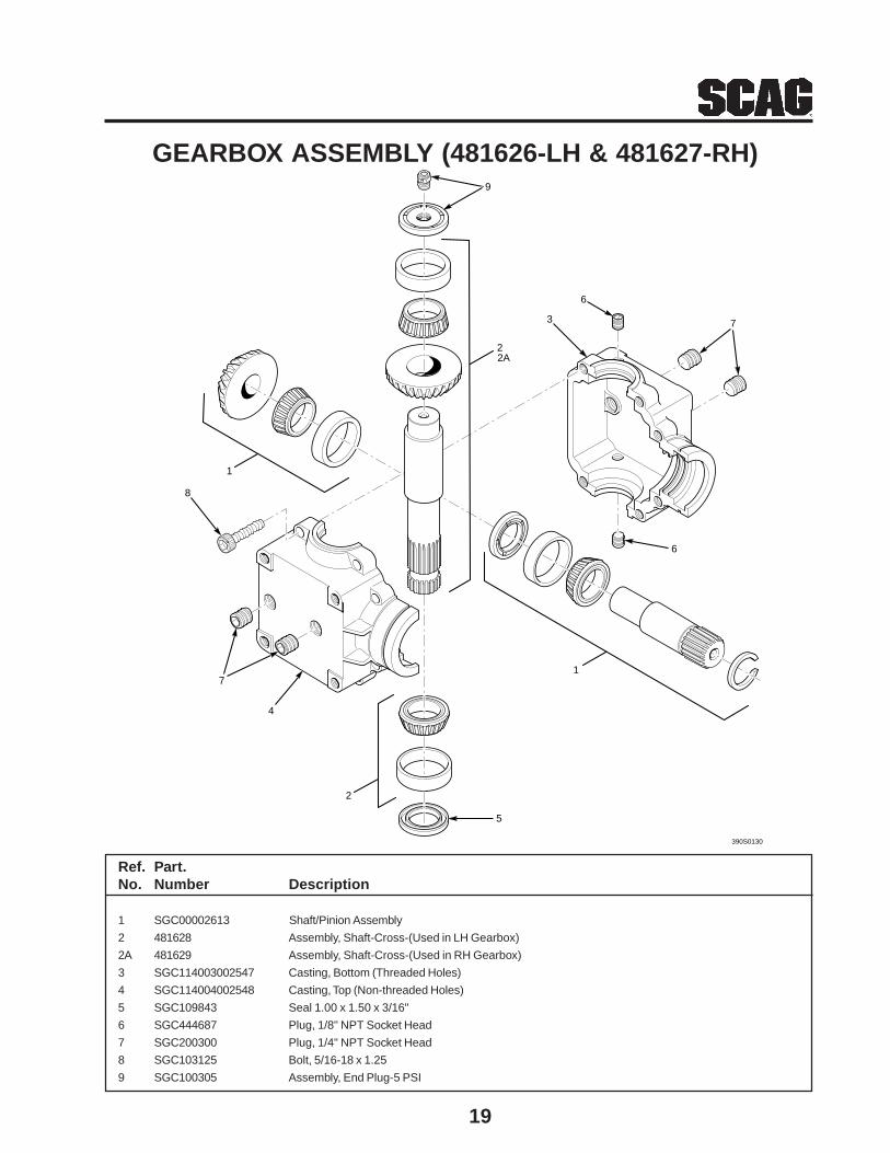
19
GEARBOX ASSEMBLY (481626-LH & 481627-RH)
Ref. Part.No. Number Description
1 SGC00002613 Shaft/Pinion Assembly
2 481628 Assembly, Shaft-Cross-(Used in LH Gearbox)
2A 481629 Assembly, Shaft-Cross-(Used in RH Gearbox)
3 SGC114003002547 Casting, Bottom (Threaded Holes)
4 SGC114004002548 Casting, Top (Non-threaded Holes)
5 SGC109843 Seal 1.00 x 1.50 x 3/16"
6 SGC444687 Plug, 1/8" NPT Socket Head
7 SGC200300 Plug, 1/4" NPT Socket Head
8 SGC103125 Bolt, 5/16-18 x 1.25
9 SGC100305 Assembly, End Plug-5 PSI
390S0130
2
5
6
1
7
6
3
1
8
7
4
2
9
2A

20
3
2
4
6
14 15
40
40
10
16
17
18
20
464219
22
21
2726
25
4524
23
28
44
2930
3132
33
34
35 36
37
390S0066
38
32
39
41
8
DECK DRIVE
15
5
4313
1
11
9
8
12
4415
7
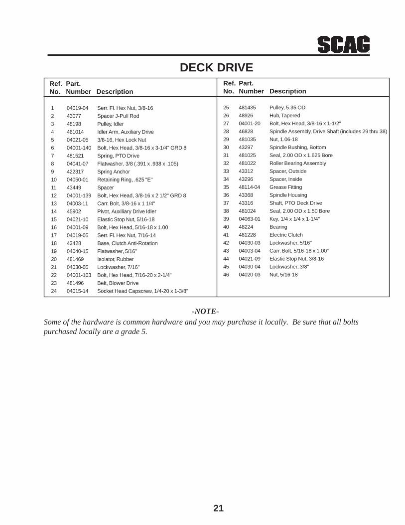
21
Ref. Part.No. Number Description
25 481435 Pulley, 5.35 OD
26 48926 Hub, Tapered
27 04001-20 Bolt, Hex Head, 3/8-16 x 1-1/2"
28 46828 Spindle Assembly, Drive Shaft (includes 29 thru 38)
29 481035 Nut, 1.06-18
30 43297 Spindle Bushing, Bottom
31 481025 Seal, 2.00 OD x 1.625 Bore
32 481022 Roller Bearing Assembly
33 43312 Spacer, Outside
34 43296 Spacer, Inside
35 48114-04 Grease Fitting
36 43368 Spindle Housing
37 43316 Shaft, PTO Deck Drive
38 481024 Seal, 2.00 OD x 1.50 Bore
39 04063-01 Key, 1/4 x 1/4 x 1-1/4"
40 48224 Bearing
41 481228 Electric Clutch
42 04030-03 Lockwasher, 5/16"
43 04003-04 Carr. Bolt, 5/16-18 x 1.00"
44 04021-09 Elastic Stop Nut, 3/8-16
45 04030-04 Lockwasher, 3/8"
46 04020-03 Nut, 5/16-18
Ref. Part.No. Number Description
1 04019-04 Serr. Fl. Hex Nut, 3/8-16
2 43077 Spacer J-Pull Rod
3 48198 Pulley, Idler
4 461014 Idler Arm, Auxiliary Drive
5 04021-05 3/8-16, Hex Lock Nut
6 04001-140 Bolt, Hex Head, 3/8-16 x 3-1/4" GRD 8
7 481521 Spring, PTO Drive
8 04041-07 Flatwasher, 3/8 (.391 x .938 x .105)
9 422317 Spring Anchor
10 04050-01 Retaining Ring, .625 "E"
11 43449 Spacer
12 04001-139 Bolt, Hex Head, 3/8-16 x 2 1/2" GRD 8
13 04003-11 Carr. Bolt, 3/8-16 x 1 1/4"
14 45902 Pivot, Auxiliary Drive Idler
15 04021-10 Elastic Stop Nut, 5/16-18
16 04001-09 Bolt, Hex Head, 5/16-18 x 1.00
17 04019-05 Serr. Fl. Hex Nut, 7/16-14
18 43428 Base, Clutch Anti-Rotation
19 04040-15 Flatwasher, 5/16"
20 481469 Isolator, Rubber
21 04030-05 Lockwasher, 7/16"
22 04001-103 Bolt, Hex Head, 7/16-20 x 2-1/4"
23 481496 Belt, Blower Drive
24 04015-14 Socket Head Capscrew, 1/4-20 x 1-3/8"
DECK DRIVE
-NOTE-Some of the hardware is common hardware and you may purchase it locally. Be sure that all boltspurchased locally are a grade 5.
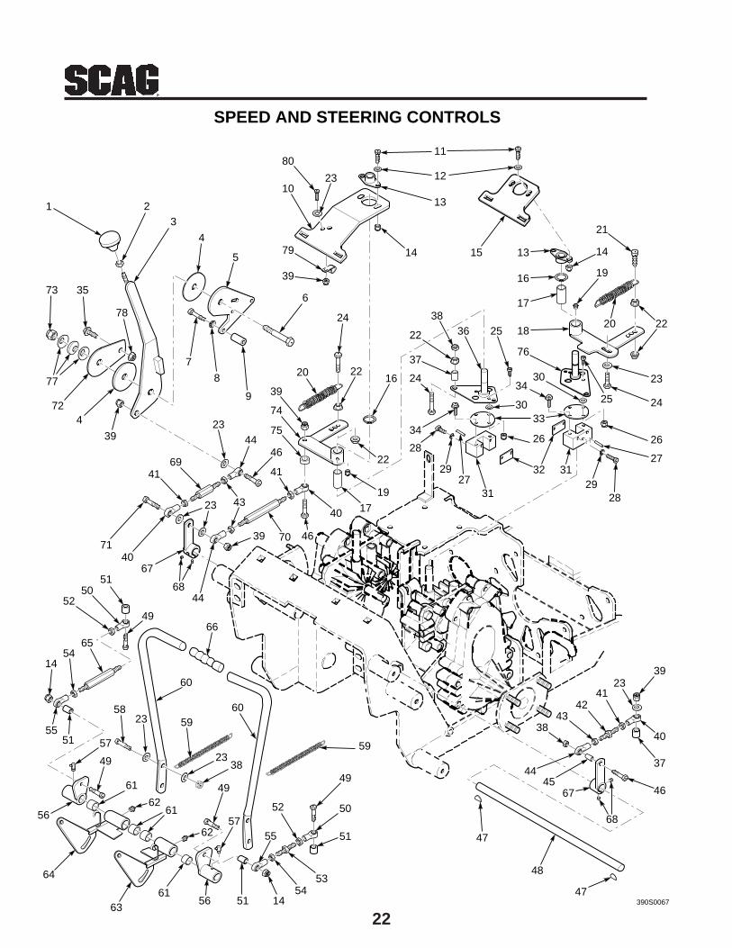
22
1 23
4
5
6
7
8
9
10
11
12
15
13
14 13
21
14
19
2220
16
17
18
23
2425
26
27
2829
3132
26
33
34
30
30
76
253638
22
37
24
34
28
29
3127
2341
4243
38
37
40
39
46
68
6745
44
47390S0067
48
47
49
50
51
1454
53
515661
63
61
64
56
49
5257
59
59
49
575155
1454
65
5052
51
4966
4468
6740
71
23 43
4169
2344
46
41
40
467039
17
19
22
1622
24
20
39
75
74
39
4
73
72
77
35
78
SPEED AND STEERING CONTROLS
62
79
39
80
23
62
61
60
605823
2338
55
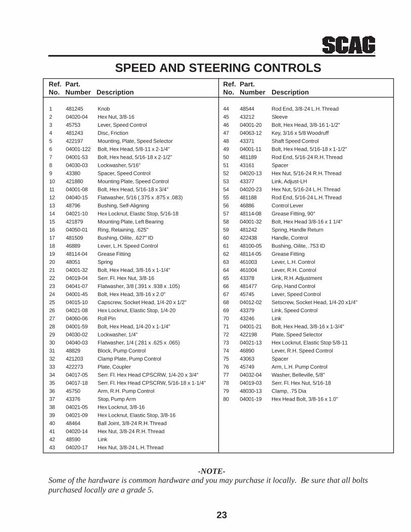
23
1 481245 Knob
2 04020-04 Hex Nut, 3/8-16
3 45753 Lever, Speed Control
4 481243 Disc, Friction
5 422197 Mounting, Plate, Speed Selector
6 04001-122 Bolt, Hex Head, 5/8-11 x 2-1/4"
7 04001-53 Bolt, Hex head, 5/16-18 x 2-1/2"
8 04030-03 Lockwasher, 5/16"
9 43380 Spacer, Speed Control
10 421880 Mounting Plate, Speed Control
11 04001-08 Bolt, Hex Head, 5/16-18 x 3/4"
12 04040-15 Flatwasher, 5/16 (.375 x .875 x .083)
13 48796 Bushing, Self-Aligning
14 04021-10 Hex Locknut, Elastic Stop, 5/16-18
15 421879 Mounting Plate, Left Bearing
16 04050-01 Ring, Retaining, .625"
17 481509 Bushing, Oilite, .627" ID
18 46889 Lever, L.H. Speed Control
19 48114-04 Grease Fitting
20 48051 Spring
21 04001-32 Bolt, Hex Head, 3/8-16 x 1-1/4"
22 04019-04 Serr. Fl. Hex Nut, 3/8-16
23 04041-07 Flatwasher, 3/8 (.391 x .938 x .105)
24 04001-45 Bolt, Hex Head, 3/8-16 x 2.0"
25 04015-10 Capscrew, Socket Head, 1/4-20 x 1/2"
26 04021-08 Hex Locknut, Elastic Stop, 1/4-20
27 04060-06 Roll Pin
28 04001-59 Bolt, Hex Head, 1/4-20 x 1-1/4"
29 04030-02 Lockwasher, 1/4"
30 04040-03 Flatwasher, 1/4 (.281 x .625 x .065)
31 48829 Block, Pump Control
32 421203 Clamp Plate, Pump Control
33 422273 Plate, Coupler
34 04017-05 Serr. Fl. Hex Head CPSCRW, 1/4-20 x 3/4"
35 04017-18 Serr. Fl. Hex Head CPSCRW, 5/16-18 x 1-1/4"
36 45750 Arm, R.H. Pump Control
37 43376 Stop, Pump Arm
38 04021-05 Hex Locknut, 3/8-16
39 04021-09 Hex Locknut, Elastic Stop, 3/8-16
40 48464 Ball Joint, 3/8-24 R.H. Thread
41 04020-14 Hex Nut, 3/8-24 R.H. Thread
42 48590 Link
43 04020-17 Hex Nut, 3/8-24 L.H. Thread
Ref. Part.No. Number Description
44 48544 Rod End, 3/8-24 L.H. Thread
45 43212 Sleeve
46 04001-20 Bolt, Hex Head, 3/8-16 1-1/2"
47 04063-12 Key, 3/16 x 5/8 Woodruff
48 43371 Shaft Speed Control
49 04001-11 Bolt, Hex Head, 5/16-18 x 1-1/2"
50 481189 Rod End, 5/16-24 R.H. Thread
51 43161 Spacer
52 04020-13 Hex Nut, 5/16-24 R.H. Thread
53 43377 Link, Adjust-LH
54 04020-23 Hex Nut, 5/16-24 L.H. Thread
55 481188 Rod End, 5/16-24 L.H. Thread
56 46886 Control Lever
57 48114-08 Grease Fitting, 90°
58 04001-32 Bolt, Hex Head 3/8-16 x 1 1/4"
59 481242 Spring, Handle Return
60 422438 Handle, Control
61 48100-05 Bushing, Oilite, .753 ID
62 48114-05 Grease Fitting
63 461003 Lever, L.H. Control
64 461004 Lever, R.H. Control
65 43378 Link, R.H. Adjustment
66 481477 Grip, Hand Control
67 45745 Lever, Speed Control
68 04012-02 Setscrew, Socket Head, 1/4-20 x1/4"
69 43379 Link, Speed Control
70 43246 Link
71 04001-21 Bolt, Hex Head, 3/8-16 x 1-3/4"
72 422198 Plate, Speed Selector
73 04021-13 Hex Locknut, Elastic Stop 5/8-11
74 46890 Lever, R.H. Speed Control
75 43063 Spacer
76 45749 Arm, L.H. Pump Control
77 04032-04 Washer, Belleville, 5/8"
78 04019-03 Serr. Fl. Hex Nut, 5/16-18
79 48030-13 Clamp, .75 Dia
80 04001-19 Hex Head Bolt, 3/8-16 x 1.0"
Ref. Part.No. Number Description
SPEED AND STEERING CONTROLS
-NOTE-Some of the hardware is common hardware and you may purchase it locally. Be sure that all boltspurchased locally are a grade 5.
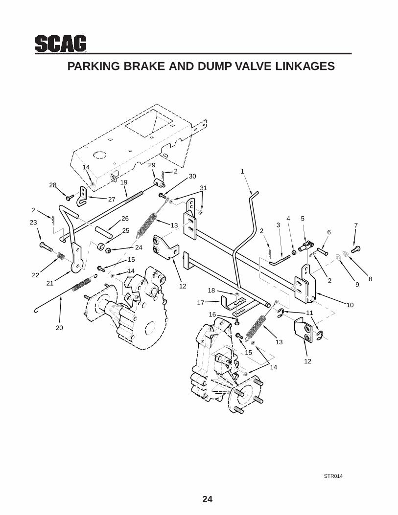
24
PARKING BRAKE AND DUMP VALVE LINKAGES
STR014
1
23
4 5
67
89
1011
12
13
14
15
16
17
1812
20
2122
23
15
14
24
25
26
27
28
14 292
19
13
31
2
2
30

25
Ref. Part.No. Number Description
1 45808 Lever, Dump Valve
2 04062-02 Hairpin
3 44116 Rod, Brake - L.H.
4 04020-22 Hex Nut, 1/4-28
5 48343-03 Clevis
6 04064-12 Pin, Clevis, 1/4 x 3/4"
7 04001-20 Bolt, Hex Head, 3/8-16 x 1-1/2"
8 04030-04 Lockwasher, 3/8"
9 04041-07 Flatwasher, 3/8 (.391 x .938 x .105)
10 45805 Actuator, Brake
11 04050-10 Ring, Retainer
12 45841 Mounting Bracket, Dump Valve
13 48840 Cable Assembly, Parking Brake
14 04019-03 Serr. Fl. Hex Nut, 5/16-18
15 04017-17 Serr. Fl. Hex Head CPSCR, 5/16-18 x 1.00"
16 04003-02 Carriage Bolt, 1/4-20 x 3/4"
PARKING BRAKE AND DUMP VALVE LINKAGESRef. Part.No. Number Description
17 422183 Bracket, Dump Valve Lever
18 04019-02 Serr. Fl. Hex Nut, 1/4-20
19 44117 Rod, Brake - R.H.
20 48950 Spring
21 45806 Lever, Parking Brake
22 48050 Spring, Control Detent
23 04001-46 Bolt, Hex Head, 3/8-16 x 2-1/4"
24 04021-09 Hex Locknut, Elastic Stop, 3/8-16
25 43063 Spacer
26 481365 Grip, Parking Brake Lever
27 422084 Latch, Brake Lever
28 04017-16 Serr. Fl. Hex Head CPSCRW, 5/16-18 x 3/4"
29 43032 Swivel Joint
30 04001-59 Bolt, Hex Head, 1/4-20 x 1-1/4"
31 04019-02 Serr. Fl. Hex Nut, 1/4-20
-NOTE-Some of the hardware is common hardware and you may purchase it locally. Be sure that all boltspurchased locally are a grade 5.
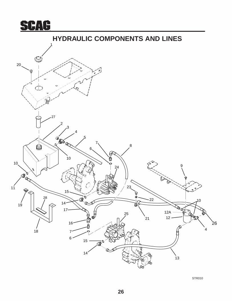
26
HYDRAULIC COMPONENTS AND LINES
STR010
1
23
4
5
6
78
9
10
4
12
1314
156
7
16
17
21
22
23
24
25
14
15
18
19
11
1010
20
12A
26
27
28
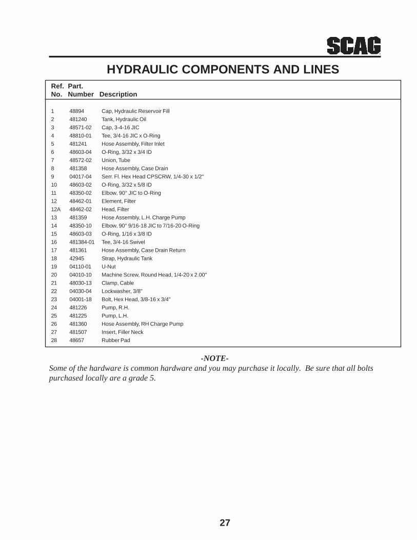
27
Ref. Part.No. Number Description
1 48894 Cap, Hydraulic Reservoir Fill
2 481240 Tank, Hydraulic Oil
3 48571-02 Cap, 3-4-16 JIC
4 48810-01 Tee, 3/4-16 JIC x O-Ring
5 481241 Hose Assembly, Filter Inlet
6 48603-04 O-Ring, 3/32 x 3/4 ID
7 48572-02 Union, Tube
8 481358 Hose Assembly, Case Drain
9 04017-04 Serr. Fl. Hex Head CPSCRW, 1/4-30 x 1/2"
10 48603-02 O-Ring, 3/32 x 5/8 ID
11 48350-02 Elbow, 90° JIC to O-Ring
12 48462-01 Element, Filter
12A 48462-02 Head, Filter
13 481359 Hose Assembly, L.H. Charge Pump
14 48350-10 Elbow, 90° 9/16-18 JIC to 7/16-20 O-Ring
15 48603-03 O-Ring, 1/16 x 3/8 ID
16 481384-01 Tee, 3/4-16 Swivel
17 481361 Hose Assembly, Case Drain Return
18 42945 Strap, Hydraulic Tank
19 04110-01 U-Nut
20 04010-10 Machine Screw, Round Head, 1/4-20 x 2.00"
21 48030-13 Clamp, Cable
22 04030-04 Lockwasher, 3/8"
23 04001-18 Bolt, Hex Head, 3/8-16 x 3/4"
24 481226 Pump, R.H.
25 481225 Pump, L.H.
26 481360 Hose Assembly, RH Charge Pump
27 481507 Insert, Filler Neck
28 48657 Rubber Pad
HYDRAULIC COMPONENTS AND LINES
-NOTE-Some of the hardware is common hardware and you may purchase it locally. Be sure that all boltspurchased locally are a grade 5.
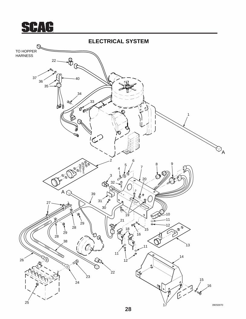
28
24
1
2
3
45
6
7
20
98
10
11
12
13
14
17
15
16
390S0070
11
11
12
18
19
1615
21
2223
25
26
27
2829
2829
39
30
31
32
33
34
3536
37
22
TO HOPPERHARNESS
ELECTRICAL SYSTEM
38
40
A
A

29
Ref. Part.No. Number Description
1 481422 Harness, Engine
2 48023 Hourmeter
3 48298 Fuse, 20 Amp
4 48017-02 Key & Ring Assembly
5 48017-04 Nut, Hex, 5/8-32
6 48017-03 Lockwasher, 5/8 Internal
7 46883 Instrument Panel, Top With Decal
8 48798 Keyswitch
9 48787 Switch, Mower Engagement Electric Clutch
10 48788 Relay
11 04031-01 Lockwasher, #10 External Tooth
12 04021-01 Hex Locknut, Elastic Stop, #10-32
13 48022 Ammeter
14 45798 Base, Instrument Panel
15 04030-02 Lockwasher, 1/4"
16 04001-01 Bolt, Hex Head, 1/4-20 x 3/4"
17 04110-01 U-Nut
18 481363 Throttle and Choke Controls
19 04010-01 Screw, Washer Round Head, #10-32 x 1/2"
20 48787-01 Nut, Hex, 1/2-27
ELECTRICAL SYSTEMRef. Part.No. Number Description
21 48717 Switch, Interlock - Seat
22 481474 Switch, Interlock - (Neutral and Hopper)
23 04001-44 Bolt, Hex Head, 1/4-20 x 1/2"
24 48029-16 Cable, Battery - Red
25 04020-02 Nut, Hex, 1/4-20
26 48029-17 Cable, Battery - Black
27 48030-11 Clamp, Double Cable
28 48030-10 Clamp, Cable
29 04021-10 Hex Locknut, Elastic Stop, 5/16-18
30 04021-01 Hex Locknut, Elastic Stop, #10-32
31 42413 Bracket, Fuse Holder
32 04010-11 Screw, Round Head, #10-32 x 1-1/2"
33 04031-03 Lockwasher, External Tooth, 5/16
34 04002-12 Bolt, Hex Head, M8-1.25 x 20
35 481275 Relay and Harness (incl. item 40)
36 04030-02 Lockwasher, 1/4
37 04002-14 Bolt, Hex Head, M6-1.125 x 10
38 48033-04 Nylon Sleeve, 24"
39 481421 Wire Harnes, STR
40 48788 Relay
-NOTE-Some of the hardware is common hardware and you may purchase it locally. Be sure that all boltspurchased locally are a grade 5.
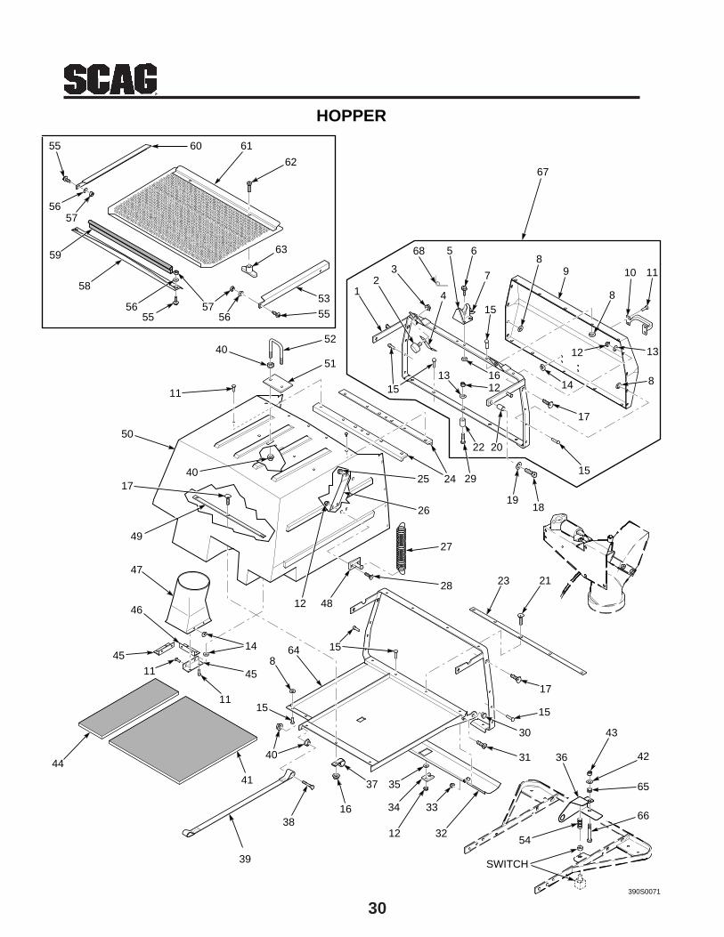
30
12
3
4
5 6
7
15
89
8
10 11
12 13
814
17
15
1819
20
161312
22
15
24 2925
26
27
28 23 21
17
15
30
31
34
12
35
16
37
38
39
40
41
44
14
45
11
11
45
46
47
12 48
15
81564
49
17
50
40
11
4052
51
53
5657
58
59
5756
60
62
63
HOPPER
55
61
5556
55
390S0071
33
32
67
SWITCH
42
65
66
43
54
36
68
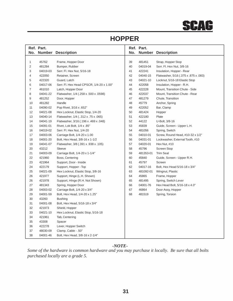
31
Ref. Part.No. Number Description
39 481451 Strap, Hopper Stop
40 04019-04 Serr. Fl. Hex Nut, 3/8-16
41 422241 Insulation, Hopper - Rear
42 04040-15 Flatwasher, 5/16 (.375 x .875 x .083)
43 04021-10 Locknut, 5/16-18 Elastic Stop
44 422058 Insulation, Hopper - R.H.
45 422228 Mount, Transition Chute - Side
46 422037 Mount, Transition Chute - Rear
47 481279 Chute, Transition
48 45779 Anchor, Spring
49 422052 Bar, Clamp
50 481424 Hopper
51 422180 Plate
52 44122 U-Bolt, 3/8-16
53 45839 Guide, Screen - Upper L.H.
54 481056 Spring, Switch
55 04010-01 Screw, Round Head, #10-32 x 1/2"
56 04031-01 Lockwasher, External Tooth, #10
57 04020-01 Hex Nut, #10
58 45796 Screen Stop
59 481353-01 Trim Seal
60 45840 Guide, Screen - Upper R.H.
61 45797 Screen
62 04017-16 Bolt, Hex Head 5/16-18 x 3/4"
63 481092-01 Wingnut, Plastic
64 45865 Frame, Hopper
65 481495 Spring, Switch Lever
66 04001-76 Hex Head Bolt, 5/16-18 x 4.0"
67 46864 Door Assy, Hopper
68 481519 Spring, Torsion
Ref. Part.No. Number Description
1 45762 Frame, Hopper Door
2 481284 Bumper, Rubber
3 04019-03 Serr. Fl. Hex Nut, 5/16-18
4 422050 Retainer, Screen
5 422320 Guard, Latch
6 04017-06 Serr. Fl. Hex Head CPSCR, 1/4-20 x 1.00"
7 461010 Latch, Hopper Door
8 04041-22 Flatwasher, 1/4 (.258 x .500 x .0598)
9 481252 Door, Hopper
10 481282 Handle
11 04090-02 Pop Rivet, 3/16 x .652"
12 04021-08 Hex Locknut, Elastic Stop, 1/4-20
13 04040-14 Flatwasher, 1/4 (..312 x .75 x .065)
14 04041-19 Flatwasher, 3/16 (.196 x .469 x .048)
15 04091-01 Rivet, Lok Bolt, 1/4 x .85"
16 04019-02 Serr. Fl. Hex Nut, 1/4-20
17 04003-06 Carriage Bolt, 1/4-20 x 1.00
18 04001-20 Bolt, Hex Head, 3/8-16 x 1-1/2
19 04041-07 Flatwasher, 3/8 (.391 x .938 x .105)
20 43212 Sleeve
21 04003-09 Carriage Bolt, 1/4-20 x 1-1/4"
22 421960 Boss, Centering
23 421964 Support, Door - Inside
24 422179 Support, Hopper - Top
25 04021-09 Hex Locknut, Elastic Stop, 3/8-16
26 421977 Support, Hinge (L.H. Shown)
26 421978 Support, HInge (R.H. Not Shown)
27 481343 Spring, Hopper Door
28 04003-02 Carriage Bolt, 1/4-20 x 3/4"
29 04001-59 Bolt, Hex Head, 1/4-20 x 1.25"
30 43260 Bushing
31 04001-08 Bolt, Hex Head, 5/16-18 x 3/4"
32 421973 Shield, Hopper
33 04021-10 Hex Locknut, Elastic Stop, 5/16-18
34 421961 Tab, Centering
35 43308 Spacer
36 422278 Lever, Hopper Switch
37 48030-09 Clamp, Cable - .50"
38 04001-46 Bolt, Hex Head, 3/8-16 x 2-1/4"
HOPPER
-NOTE-Some of the hardware is common hardware and you may purchase it locally. Be sure that all boltspurchased locally are a grade 5.
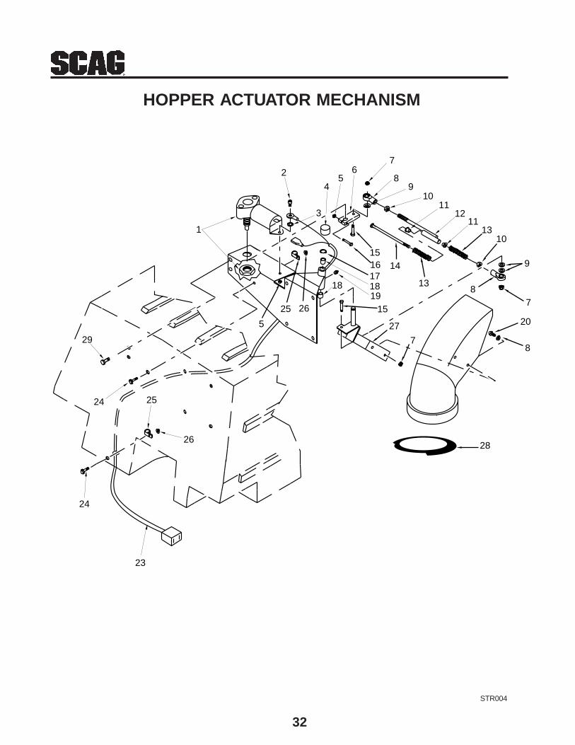
32
STR004
HOPPER ACTUATOR MECHANISM
1
2
3
45
67
89
1011
1211
1310
9
78
13
141516171819
18
15
27
7
20
8
2625
5
29
24
24
26
25
23
28
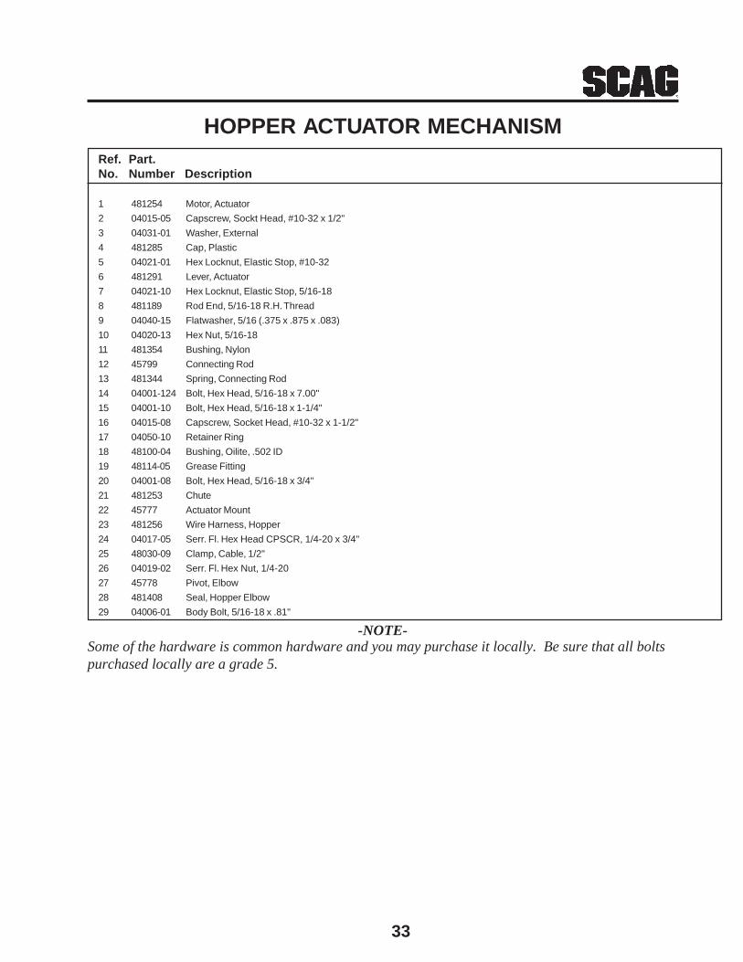
33
Ref. Part.No. Number Description
1 481254 Motor, Actuator
2 04015-05 Capscrew, Sockt Head, #10-32 x 1/2"
3 04031-01 Washer, External
4 481285 Cap, Plastic
5 04021-01 Hex Locknut, Elastic Stop, #10-32
6 481291 Lever, Actuator
7 04021-10 Hex Locknut, Elastic Stop, 5/16-18
8 481189 Rod End, 5/16-18 R.H. Thread
9 04040-15 Flatwasher, 5/16 (.375 x .875 x .083)
10 04020-13 Hex Nut, 5/16-18
11 481354 Bushing, Nylon
12 45799 Connecting Rod
13 481344 Spring, Connecting Rod
14 04001-124 Bolt, Hex Head, 5/16-18 x 7.00"
15 04001-10 Bolt, Hex Head, 5/16-18 x 1-1/4"
16 04015-08 Capscrew, Socket Head, #10-32 x 1-1/2"
17 04050-10 Retainer Ring
18 48100-04 Bushing, Oilite, .502 ID
19 48114-05 Grease Fitting
20 04001-08 Bolt, Hex Head, 5/16-18 x 3/4"
21 481253 Chute
22 45777 Actuator Mount
23 481256 Wire Harness, Hopper
24 04017-05 Serr. Fl. Hex Head CPSCR, 1/4-20 x 3/4"
25 48030-09 Clamp, Cable, 1/2"
26 04019-02 Serr. Fl. Hex Nut, 1/4-20
27 45778 Pivot, Elbow
28 481408 Seal, Hopper Elbow
29 04006-01 Body Bolt, 5/16-18 x .81"
HOPPER ACTUATOR MECHANISM
-NOTE-Some of the hardware is common hardware and you may purchase it locally. Be sure that all boltspurchased locally are a grade 5.
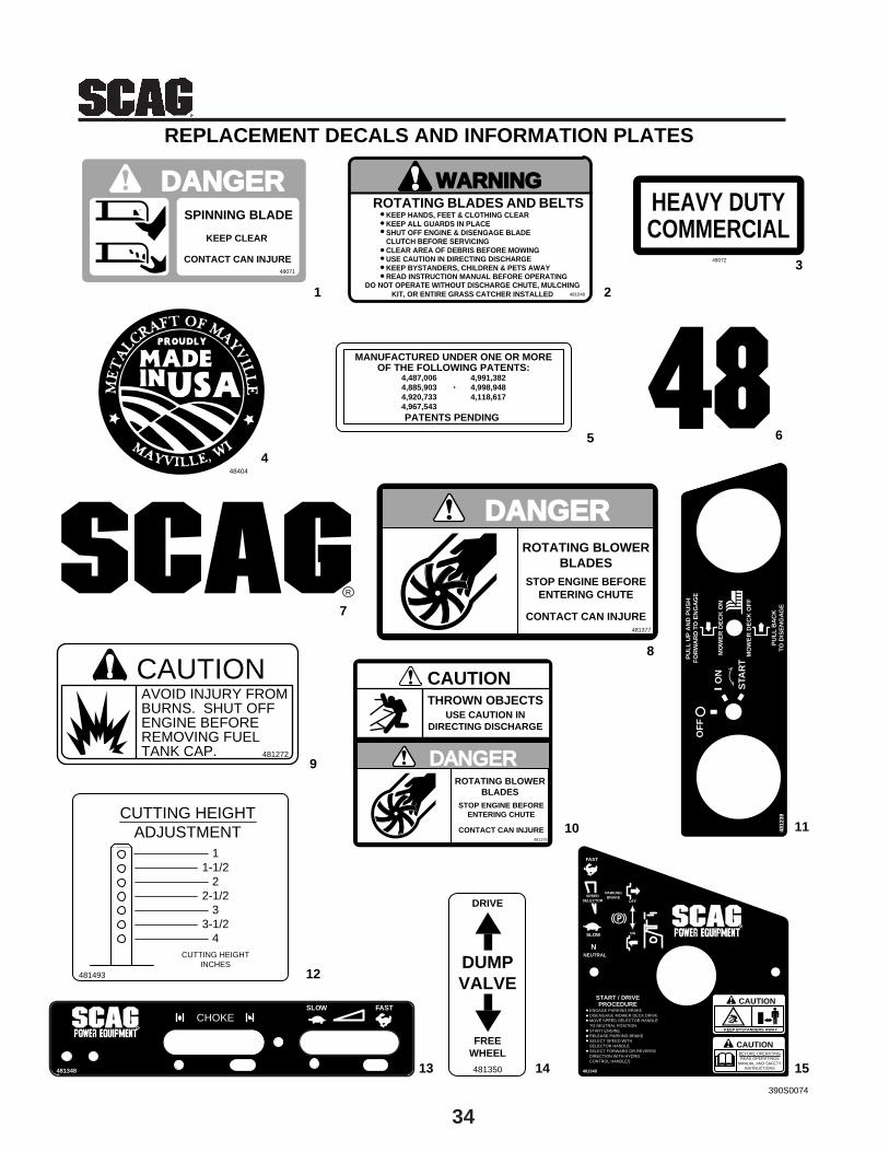
34
REPLACEMENT DECALS AND INFORMATION PLATES
1 2
3
65
4
7
9
12
13 14 15
10 11
8
48072
HEAVY DUTYCOMMERCIAL
ROTATING BLADES AND BELTSWARNING
KEEP HANDS, FEET & CLOTHING CLEARKEEP ALL GUARDS IN PLACESHUT OFF ENGINE & DISENGAGE BLADECLUTCH BEFORE SERVICINGCLEAR AREA OF DEBRIS BEFORE MOWINGUSE CAUTION IN DIRECTING DISCHARGEKEEP BYSTANDERS, CHILDREN & PETS AWAYREAD INSTRUCTION MANUAL BEFORE OPERATING
DO NOT OPERATE WITHOUT DISCHARGE CHUTE, MULCHINGKIT, OR ENTIRE GRASS CATCHER INSTALLED 481040
MANUFACTURED UNDER ONE OR MOREOF THE FOLLOWING PATENTS:
PATENTS PENDING
4,487,0064,885,9034,920,7334,967,543
4,991,3824,998,9484,118,617
DANGERSPINNING BLADE
KEEP CLEAR
CONTACT CAN INJURE48071
R
DANGERROTATING BLOWER
BLADESSTOP ENGINE BEFORE
ENTERING CHUTE
CONTACT CAN INJURE481377
CAUTIONAVOID INJURY FROMBURNS. SHUT OFFENGINE BEFOREREMOVING FUELTANK CAP. 481272
CUTTING HEIGHTADJUSTMENT
11-1/2
22-1/2
33-1/2
4CUTTING HEIGHT
INCHES481493
CHOKESLOW FAST
R
481348
PARKINGBRAKE
OFF
ON
R
FAST
SLOW
SPEEDSELECTOR
CAUTION
KEEP BYSTANDERS AWAY
CAUTIONBEFORE OPERATINGREAD OPERATINGS
MANUAL AND SAFETYINSTRUCTIONS
START / DRIVEPROCEDURE
ENGAGE PARKING BRAKEDISENGAGE MOWER DECK DRIVEMOVE SPEED SELECTOR HANDLETO NEUTRAL POSITIONSTART ENGINERELEASE PARKING BRAKESELECT SPEED WITHSELECTOR HANDLESELECT FORWARD OR REVERSEDIRECTION WITH HYDROCONTROL HANDLES
481349
NEUTRAL
N
DANGERROTATING BLOWER
BLADESSTOP ENGINE BEFORE
ENTERING CHUTE
CONTACT CAN INJURE481378
USE CAUTION INDIRECTING DISCHARGE
THROWN OBJECTS
CAUTIONP
ULL
UP
AN
D P
US
H
FO
RW
AR
D T
O E
NG
AG
E
MO
WE
R D
EC
K O
NO
N
STA
RT
MO
WE
R D
EC
K O
FF
PU
LL B
AC
KTO
DIS
EN
GA
GE
OF
F
4812
39
48404
390S0074
DUMPVALVE
FREEWHEEL
481350
DRIVE
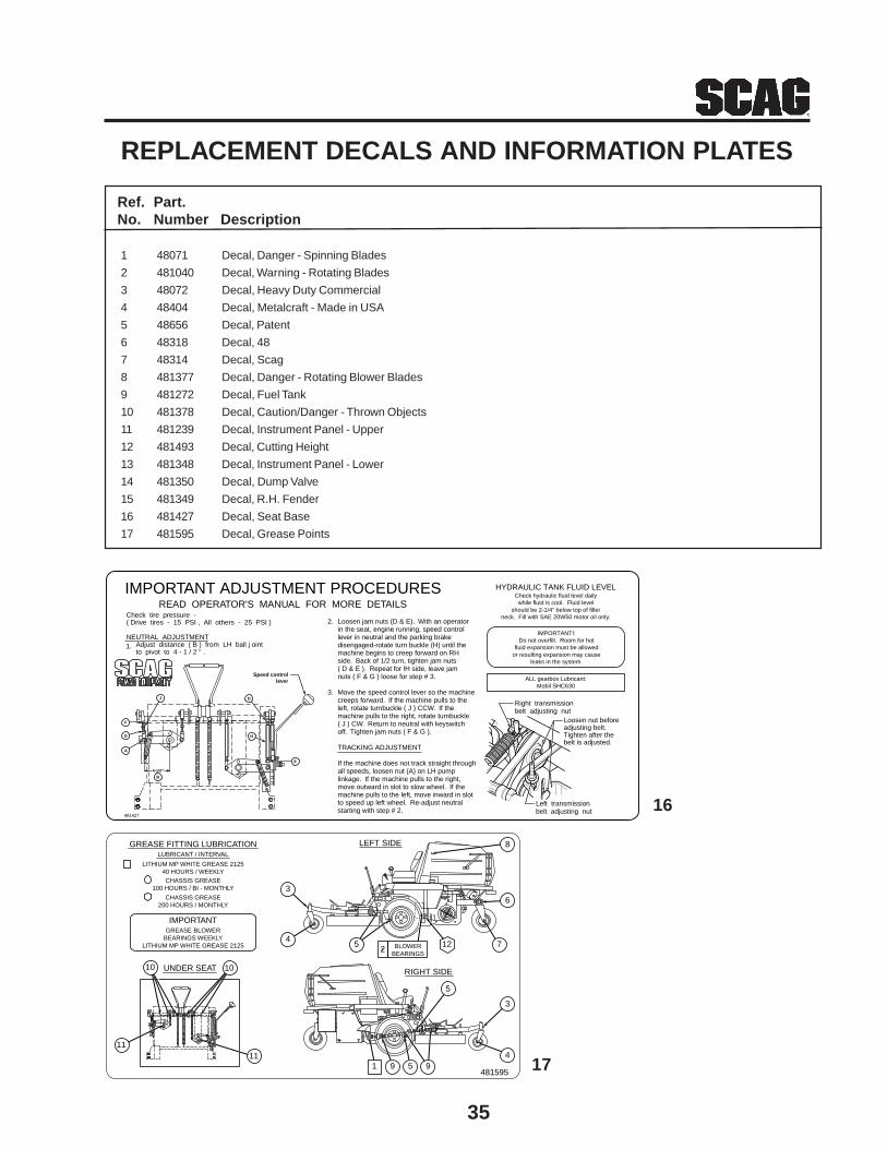
35
Ref. Part.No. Number Description
1 48071 Decal, Danger - Spinning Blades
2 481040 Decal, Warning - Rotating Blades
3 48072 Decal, Heavy Duty Commercial
4 48404 Decal, Metalcraft - Made in USA
5 48656 Decal, Patent
6 48318 Decal, 48
7 48314 Decal, Scag
8 481377 Decal, Danger - Rotating Blower Blades
9 481272 Decal, Fuel Tank
10 481378 Decal, Caution/Danger - Thrown Objects
11 481239 Decal, Instrument Panel - Upper
12 481493 Decal, Cutting Height
13 481348 Decal, Instrument Panel - Lower
14 481350 Decal, Dump Valve
15 481349 Decal, R.H. Fender
16 481427 Decal, Seat Base
17 481595 Decal, Grease Points
REPLACEMENT DECALS AND INFORMATION PLATES
R
Right transmissionbelt adjusting nut
481427
Speed controllever
E
H
F
G
A
4-1/2"
J D
IMPORTANT ADJUSTMENT PROCEDURESREAD OPERATOR'S MANUAL FOR MORE DETAILS
IMPORTANT!:Do not overfill. Room for hot
fluid expansion must be allowedor resulting expansion may cause
leaks in the system.
ALL gearbox Lubricant:Mobil SHC630
Check hydraulic fluid level dailywhile fluid is cool. Fluid level
should be 2-1/4" below top of fillerneck. Fill with SAE 20W50 motor oil only.
HYDRAULIC TANK FLUID LEVEL
Left transmissionbelt adjusting nut
Loosen nut beforeadjusting belt.Tighten after thebelt is adjusted.
Check tire pressure -( Drive tires - 15 PSI , All others - 25 PSI )
NEUTRAL ADJUSTMENT Adjust distance ( B ) from LH ball j oint to pivot to 4 - 1 / 2 " .1.
Loosen jam nuts (D & E). With an operatorin the seat, engine running, speed controllever in neutral and the parking brakedisengaged-rotate turn buckle (H) until themachine begins to creep forward on RHside. Back of 1/2 turn, tighten jam nuts( D & E ). Repeat for lH side, leave jamnuts ( F & G ) loose for step # 3.
Move the speed control lever so the machinecreeps forward. If the machine pulls to theleft, rotate turnbuckle ( J ) CCW. If themachine pulls to the right, rotate turnbuckle( J ) CW. Return to neutral with keyswitchoff. Tighten jam nuts ( F & G ).
TRACKING ADJUSTMENT
If the machine does not track straight throughall speeds, loosen nut (A) on LH pumplinkage. If the machine pulls to the right,move outward in slot to slow wheel. If themachine pulls to the left, move inward in slotto speed up left wheel. Re-adjust neutralstarting with step # 2.
2.
3.
B
16
IMPORTANTGREASE BLOWER
BEARINGS WEEKLYLITHIUM MP WHITE GREASE 2125
UNDER SEAT
GREASE FITTING LUBRICATIONLUBRICANT / INTERVAL
LITHIUM MP WHITE GREASE 212540 HOURS / WEEKLYCHASSIS GREASE
100 HOURS / BI - MONTHLY
CHASSIS GREASE200 HOURS / MONTHLY
RIGHT SIDE
LEFT SIDE
481595
1111
1 9 5 94
3
5
4
3
5 12BLOWERBEARINGS
7
6
8
1010
2
17
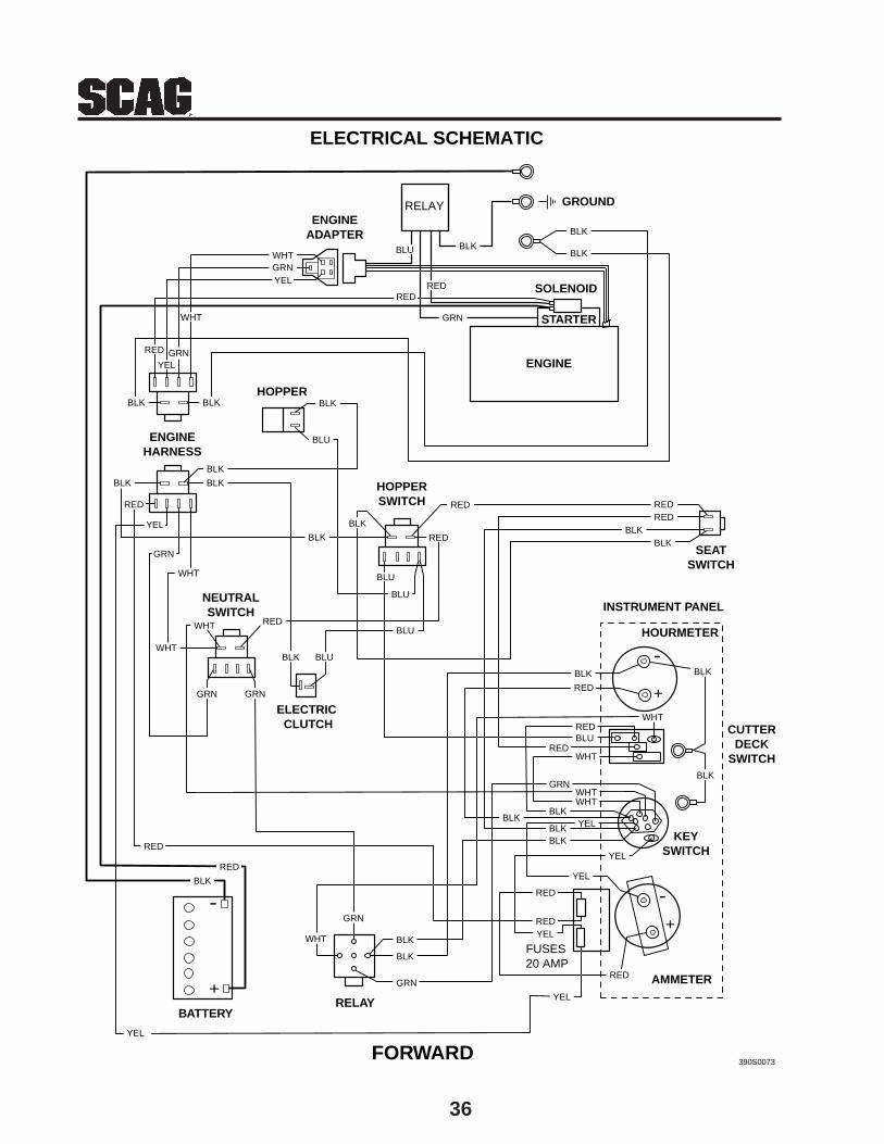
36
SEATSWITCH
+
-
GRN
INSTRUMENT PANEL
HOURMETER
CUTTERDECK
SWITCH
KEYSWITCH
AMMETER
ELECTRIC CLUTCH
NEUTRALSWITCH
HOPPERSWITCH
HOPPER
BATTERYRELAY
FORWARD
ENGINEADAPTER
GROUND
SOLENOID
STARTER
ENGINE
FUSES20 AMP
+
-+
-
RED
BLKBLK
REDRED
BLU
BLU
BLK
BLU
BLK
BLK
BLK
BLK
GRN
WHT
GRN
RED
BLK
GRN
RED
RED
WHT
GRN
WHT
YEL
BLU
BLK
BLK
BLU
BLK
BLKBLK
ENGINEHARNESS
RED
BLKBLK
RED
BLK
BLK
YEL
WHT
YELGRN
WHT
RED
ELECTRICAL SCHEMATIC
RED
YEL
RED
YEL
RED
YEL
YEL
BLK
390S0073
BLK
REDWHT
BLU
RED
REDWHT
WHTWHT
GRN
YELBLK
BLKBLKBLK
RED
YEL
GRN
WHT
BLK
RED
GRN
BLU
RELAY

������������� ��������������������� ��������� �������������� ������������������������� ����������������������� ������������������������������ ������������
��� ������������������� ������������ ��������������������
������������ �������������������������������� ���������������������������������� ������������������������������������������������������ ������������������������������������������������������������������������������������������ ���� ������� �����������������������������������!��"����������������������������������������������������������������������!�������������������������������������������������������������������������������!��������������������������������������������������� ��� ������� �����!
"�������������������������������������������������������������������������������������������������������������������������������#
$ %������������������������������������������������������������������������&'�����!$ (����������������������&'�����!$ )�����������������������������������������������������������������������������������������������*�����!
$ �����������������������������������������������������������+����������������!$ �������������������������������������*��������������������������������������������������� ������������������!��,�-������������������������������������������������������������.!
$ �����������������������������������������*�����!
���� ������������������������������������������������&'�������������!
"��� ���������������������������������������������������������������������� ���� ������� �������������������������������!"����-����������������������������������������������������������������-��������������������������������������������������������������������!�� ���+�������������������������������������������������������������������������������������������������������������������������������������������������������� ��������!
"�������������������������������������������������������������������������������������������������������������������������������������������������������������������������������������������/������+��0�����!��"������������������������������������������������������������������������������������������������������������������������������������������������������������������������/������+��0�������������������0�����!��"�����������������������������������������������������������������������������������������������!��1��������������������������������-��������������������������������������������������������������������������������������������������������������� ������������������������������������ �������������������������������������������������������������!
����������������������������������������������������������������������������������������������������������������������������������������������!
������������������������������������������������������������,*.������������������������������,&'.���������������������������������!���������������������������������������������������������������������������������������������������������������������������������������������������������-�����������������������������������������������������������!�� ���+�����������������������������������������������-����������������������������������������������������������������� �������������������������������������������������������������������!�� ��������������������������������������������������������������������������������������������������������!
����������������������������������������������������������������������������������������������������-�����������������-������������������������������������������ ���� ������� �����������-���������������������������������������+�����������������������������������������������������������������������������������������������������������������������������������������������������������������������������������������������������������������������! �������������������������-������������������������������������������������������������������������������-�����������������������!
"�������������������������������������������������������������������������������������������������������!
�������+!

��������������� ������
����� ��������
%�������������� �� ����� ��������������������� �������������������