turbulent combustion - princeton university · c. k. law and c. j. sung, structure, aerodynamics,...
TRANSCRIPT

Copyright ©2016 by James F. Driscoll. This material is not to be sold, reproduced or distributed
without prior written permission of the owner, James F. Driscoll
Turbulent Combustion
Experiments and Fundamental Models
J. F. Driscoll, University of Michigan
Bell, Day, Driscoll
“corrugated” premixed DNS
PROCI 31, 1299
R. Sankaran, E. Hawkes,
Jackie Chen T. Lu, C. K. Law Premixed DNS
PROCI 31, 1291
1

Outline for the week
Mon: Physical concepts faster mixing, faster propagation, optimize liftoff, flame surface density, reaction rate, PDF Tues: Kilohertz PLIF, PIV measurements of flame structure - to assess models Wed: Non-Premixed and Premixed flames - measurements, models gas turbine example Thurs: Partially premixed flames - and some examples Fri: Future challenges: Combustion Instabilities (Growl) , Extinction
2

Motivation - premixed is the way of the future – low NOx, CO, soot What problems are important ? Background what does turbulence do ? what do we need to model and to measure ? turbulent burning velocity, flame surface density, reaction rate Turbulent reaction rate Probability density function helps to model turbulent reaction rate Fuel air mixing and Flame stability
Outline for Monday = Physical concepts
3

Good references
Fundamentals of Turbulent and Multiphase Combustion Kenneth K. Kuo and Ragini Acharya, 2012 John Wiley & Sons, Inc. Turbulent Combustion, N. Peters, Cambridge U. Press, 2000 Libby, P.A, Williams, F.A., Turbulent Reacting Flows, Academic Press, 1994 Turns, S., An Intro to Combustion, McGraw Hill, 2000 Lewis, B. and von Elbe, G., Combust. Flames, Explosions, Academic Press, 1961 Peters N. Laminar flamelet concepts in turbulent combust. Proc Comb Inst 21 1986 C. K. Law and C. J. Sung, Structure, aerodynamics, and geometry of premixed flamelets, PECS, 26, 4-6, 2000, 459-505RS J. F. Driscoll, Turbulent premixed combustion: flamelet structure and turbulent burning velocities, Prog Energy Combust Sci 34, 91-134, 2008.
4

Barlow, Turbulent Nonpremixed Flame workshop website: http://www.ca.sandia.gov/TNF/ Eckbreth, Alan, Laser Diagnostics for Combustion Temperature and Species, Combust Science Tech Pub, 1996. Lockwood, F, Naguib, A, k-epsilon model of jet flame, Comb Flame 24, 109, 1975 Pitsch H, Large-eddy simulation of turbulent combustion, Ann Rev Fluid Mech 38, 2006 Duclos JM, Veynante D, Poinsot T. A comparison of flamelet models for premixed turbulent combustion. Combust Flame 1993; 95: 1 - 16. Prasad R, Gore JP. Evaluation of flame surface density models for turbulent premixed jet flames. Combust Flame 1999; 116: 1-14. Pitsch, H., LES of turbulent piloted diffusion flame, Phys Fluids 12, 10, 2541, 2000. Kalghatgi, G.. Blowout stability limits of gaseous jet diffusion flames in still air, Combust Sci Technol 26, 233, 1981.
5

Motivation: Premixed is the way of the future - low NOx, CO, soot
premixed flame difficult to anchor Temme, Driscoll, Combust. Flame 161, 958 Tim Lieuwen – equivalence ratio oscillations PROCI 27, 1809
Engine “Growl” Steady
Pilot Flame
(non-
premixed)
MAIN Flame
(premixed)
Pilot air
Pilot fuel
Main
air
Main
fuel
LPP
GE-TAPS in Michigan High Pressure GT Combustor
6

Motivation - challenges
Most practical problems are “Partially-Premixed” Partially-Premixed = ER varies in space from 0 to ∞, a point sometimes sees premixed, sometimes non-premixed flamelets Stratified Premixed = ER varies in space, reactants are within flam. Limits see: Masri, PROCI 35, 1115, Driscoll Comb Flame 162, 2808
No dependable model of flame blowout, combustion instabilities or turbulent burning velocity at large turbulence level
- Need “robust” LES submodel: flamelets: Bray / Flame surface density progress variable (Moin, Pitsch, Ihme) thickened: Poinsot (TFM) distributed: Menon(LEM), Pope (PDF) pyrolysis chemistry (?)
- No measurements of boundaries of regimes - when are flamelet models appropriate ? - Premixed turbulent combustion is more difficult than non-premixed turbulent combustion, not just a mixing problem, also wave propagation
7

Motivation: What problems do we want to solve ?
1. Premixed: Engines: IC engine & HCCI, industrial burners, premixed GT
2. Non-premixed: jet, jet in cross flow, jet in co-flow, jet in swirl flow
3. Partially-premixed: gas turbine, afterburner, base of lifted jet
4. Canonical experiments for model assessment:
non-premixed: piloted jet flame (Sandia flame D)
premixed: Bunsen (high-Re), premixed jet, low-swirl, spherical
8

Steinberg, Driscoll Michigan kHz PIV eddies passing through flame
Comb Flame 156, 2285
Cam Carter (AFRL) Tonghun Lee (UIUC)
10 kilohertz CH Reaction layer
Applied Optics B 116: 515
Motivation– kilohertz imaging
9

Best current models ?
10

FSD = Flame surface density LES models F-TACLES Mercier, Veynante, PROCI 35, 1259, Hawkes, Cant, Comb Flame 126, 1617 See, Ihme, PROCI 35, 125, Duwig, Flow,Turb Comb 79, 433 FPV = Flamelet progress variable Pierce, Moin, J. Fluid Mech 504-73, Chen, Ihme Comb Flame 160, 2896 Lamouroux, Ihme, Comb Flame 161, 2120 TFM = Thickened flamelet model Selle, Poinsot, Comb Flame 137, 489, Esclapez, Cuenot, PROCI 35, 3133 De, Acharya, Comb Sci Technol 181, 1231 CMC = Conditional Moment Closure Amzin, Swaminathan, Comb Sci Tech 184, 1743, Amzin Cant, Comb Sci Tech 187, 1705 G-Equation Knudsen, Pitsch, Comb Flame 159, 242, Nogenmyr, Comb Flame 156, 25 LEM = Linear Eddy Model Srinivasan, Menon, FlowTurb Comb 94, 237, Sankaran, Menon, PROCI 30, 575
References – Premixed models
11
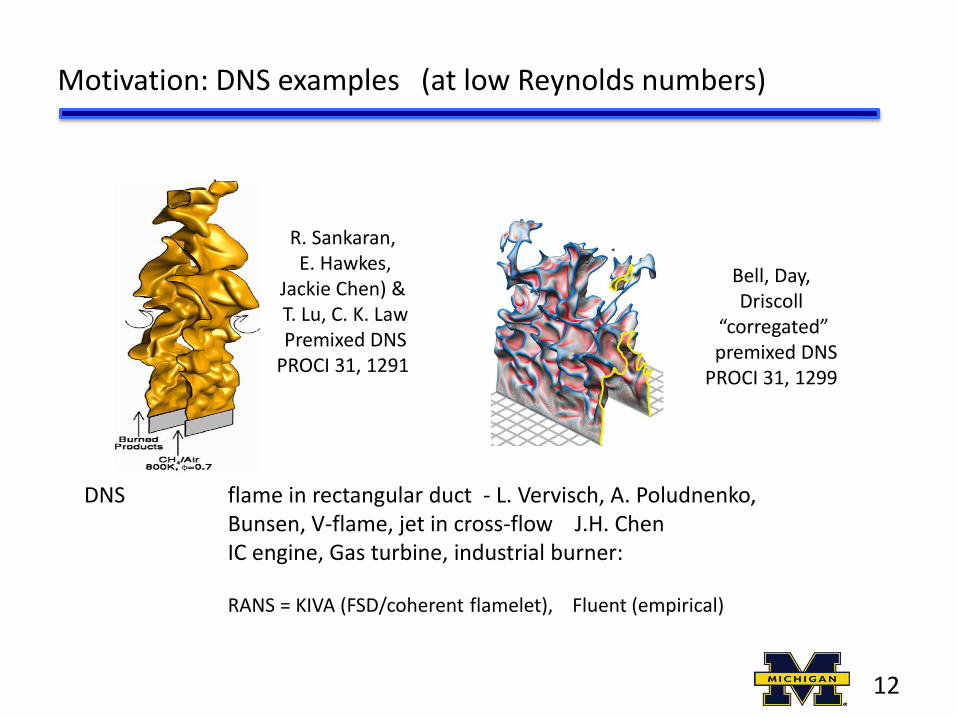
Motivation: DNS examples (at low Reynolds numbers)
Bell, Day, Driscoll
“corregated” premixed DNS
PROCI 31, 1299
R. Sankaran, E. Hawkes,
Jackie Chen) & T. Lu, C. K. Law Premixed DNS
PROCI 31, 1291
DNS flame in rectangular duct - L. Vervisch, A. Poludnenko, Bunsen, V-flame, jet in cross-flow J.H. Chen IC engine, Gas turbine, industrial burner: RANS = KIVA (FSD/coherent flamelet), Fluent (empirical)
12

Bell, Proc Natl Acad Sciences 102, 29 10006–10011
Aspden J. Fluid Mech 680, 287 Flame in a duct – periodic boundary conditions Sees broken reactions Claims to see distributed reactions
DNS - 3-D, complex chemistry
13
Background – what does turbulence do ?
Faster mixing -large turbulent diffusivity, shorter flames, smaller combustors Faster propagation - large turbulent burning velocity avoids blowout Optimize liftoff height - keep flame away from walls but do not blowout Reduce Pollutants - less NOx if velocities are large (for short residence times) and fuel-air mixing is fast and lean Avoid growl - combustion oscillations in gas turbines, rockets, due to poor flame anchoring Challenge: to model the turbulent reaction rate for non-premixed, premixed and partially-premixed combustion what are the best current models, and how good are they ?
14

Background
turbulent kinetic energy
Favre (density-weighted) average
so:
replacing mean quantities in Navier Stokes Equations with their Favre averages removes all the density fluctuations - this removes one unknown (r’) but it adds one new unknown: turbulent mass flux: which we determine using:
Prandtl’s gradient diffusion assumption
15

Gradient diffusion assumption - relates Favre avg to time average
Favre average gets rid of one unknown (r’) but introduces another one:
r
y
v’ = +
A
B Suppose and v’ are positive Small element will carry a low density from A To the higher density region at B. Therefore fluid at B will see a low density fluctuation, thus r’ is negative at B So: where L = integral scale Thus r’v’ = - L v’ taking time average eqn above We also proved that DT = v’ L
Gradient Diffusion assumption
r = - L
L
16

Since molecular viscosity m / r = (speed of sound) (mean free path) Prandtl suggested: mT / r = (u’ L) L = integral scale Dissipation rate of TKE e = u’3 /L see turbulence text by Tennekes
Since u’ = k1/2 then e = k3/2 / L or L = k3/2 / e
Since we said above mT = r (u’) ( L), then:
How do we compute k and e ? Prandlt suggested the k - equation
Mixing: Turbulent viscosity = diffusivity is large
17

How to compute turbulence level k and dissipation rate e ?
convection = diffusion + creation - destruction
k-epsilon equations
Example: Grid in a Wind tunnel , are constant, = 0 at x > 0 behind grid
Given: at x = 0 (grid) k = k0 = 10 m2/s2 and e = e0 = 1 (m/s)3/m then integrate:
Solve on MATLAB
k
x
e
x 0 0 0
18
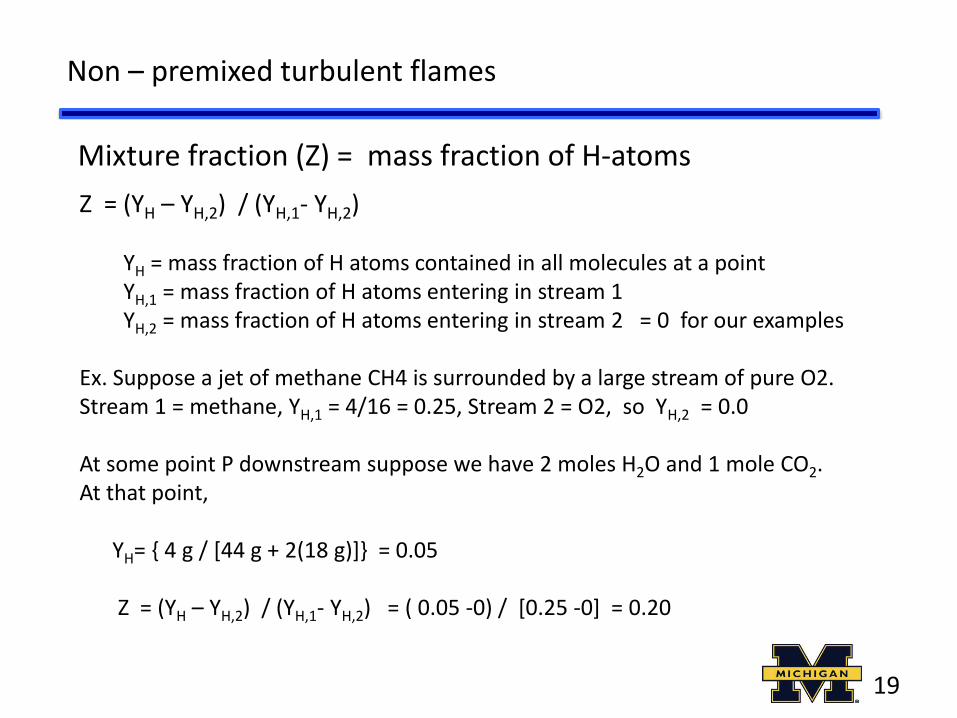
Mixture fraction (Z) = mass fraction of H-atoms
Non – premixed turbulent flames
Z = (YH – YH,2) / (YH,1- YH,2) YH = mass fraction of H atoms contained in all molecules at a point YH,1 = mass fraction of H atoms entering in stream 1 YH,2 = mass fraction of H atoms entering in stream 2 = 0 for our examples Ex. Suppose a jet of methane CH4 is surrounded by a large stream of pure O2. Stream 1 = methane, YH,1 = 4/16 = 0.25, Stream 2 = O2, so YH,2 = 0.0 At some point P downstream suppose we have 2 moles H2O and 1 mole CO2. At that point, YH= { 4 g / [44 g + 2(18 g)]} = 0.05 Z = (YH – YH,2) / (YH,1- YH,2) = ( 0.05 -0) / [0.25 -0] = 0.20
19

Conservation equations for, Z, mass fractions of H2 and O2
Now consider a planar 2-D jet of H2 surrounded by a stream of O2
Inserting these into the above and put in terms of Z to get: Mixture fraction Conservation eqn has no source term
20
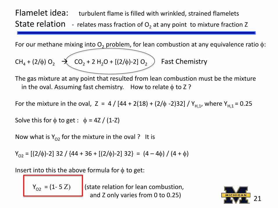
Flamelet idea: turbulent flame is filled with wrinkled, strained flamelets
State relation - relates mass fraction of O2 at any point to mixture fraction Z
For our methane mixing into O2 problem, for lean combustion at any equivalence ratio f:
CH4 + (2/f) O2 CO2 + 2 H2O + [(2/f)-2] O2 Fast Chemistry
The gas mixture at any point that resulted from lean combustion must be the mixture in the oval. Assuming fast chemistry. How to relate f to Z ? For the mixture in the oval, Z = 4 / [44 + 2(18) + (2/f -2)32] / YH,1, where YH,1 = 0.25 Solve this for f to get : f = 4Z / (1-Z) Now what is YO2 for the mixture in the oval ? It is YO2 = [(2/f)-2] 32 / {44 + 36 + [(2/f)-2] 32} = (4 – 4f) / (4 + f) Insert into this the above formula for f to get: YO2 = (1- 5 Z) (state relation for lean combustion, and Z only varies from 0 to 0.25)
21

State relations for unstrained non-premixed flamelets
Mixture fraction = mass fraction of hydrogen atoms
Pure pure Air fuel
stoichiometric
Fuel rich
Fuel lean (mass fraction)
If you know the instantaneous mixture fraction (Z) at a point P, you use these state relations to look up instantaneous temperature and mass fractions at P
22

Probability density function - used to define a mean value
P(c) dc = probability that c lies in the range between c – dc/2 and c + dc/2
P
Z State relation = Mass fraction of CO Conditioned on Z At each point in the flame, we solve
conservation equations to get the mean mixture fraction and variance in mixture fraction
Idea: you only have to solve conservation equations for and and use above integral to get other mean values; you avoid solving more conservation equations for each variable
23

Assume PDF (Z) to be a Beta function for non-premixed flames
here x = Z = mixture fraction and b are related to mean and variance of Z
P(Z)
pure Z pure air fuel
24

Importance of state relations
We could solve partial differential equations for every variable, but then we would need source terms for each. Instead use Schvab-Zeldovich approach: Assume turbulent diffusivity of mass (DT) equals that of momentum (nT) and that of heat (T) - Premixed flames: solve only the differential equation for non-dimensional
temperature, called reactedness (this is the energy eqn) and its variance
- Non-premixed flames: solve only the differential equations for mean mixture fraction (the Z equation) and its variance
- Then use state relations to compute mean values of r, T, Yi and turbulent reaction rates, using:
- Where to get the state relations ? From equilibrium chemistry, or from strained flamelet (non-equil) chemistry – we will discuss
25

Turbulence-chemistry interaction – why do we need PDFs ?
Turbulent reaction rate - the biggest unknown
The conservation equation for time-averaged CO mass fraction is:
kg/s/m3 CO produced = ?
Reaction rate depends on the JOINT PROBABILITY that: sufficient fuel, sufficient O2 and sufficient temperature are simultaneously present
That would be WRONG. Suppose a glob of pure reactants (cold) and a glob of pure products (hot) oscillate over point P, as shown:
Cold React ants
Hot products
P
You could ignore interactions and say the reaction rate is:
26

The actual temperature at P is 300 K when the reactants are present = no reaction When products are present at P, temperature is 2100 K but no reactants = no reaction If you use the time-average temperature at P, which is 2400/2 = 1200 K, and the time- average fuel-air ratio at P and plug into the above Arrhenius eqn, you compute a large reaction rate at P ! But reaction rate is nearly zero ! This is totally wrong. Reaction occurs at P only when the thin line between the reactants and products is on P; then you have simultaneously the proper fuel, O2 and temperature The correct reaction rate of CO is the following, which has the PDF in it:
Why we need PDFs, continued
27

Turbulent reaction rate of a premixed flame - proportional to FSD
Proof: Consider a wrinkled flame that at time t1 moves normal to itself at speed SL to new position at time t2
The volume/sec of reactants overtaken by the wave = (area of wave AT) Times the (distance moved /sec) of each segment of the wave distance moved / sec = SL laminar burning velocity mass/sec of reactants overtaken by the wave = rR (volume/sec overtaken) So: mass/sec of reactants overtaken = rR SL AT
But: = mass/sec/volume = rR SL (AT /volume) = rR SL S
For a premixed turbulent flame, the turbulent reaction rate at any point, in kg/sec reactants consumed/volume, is needed because it is the source term in the mean conservation of energy equation. Reaction rate is given by:
See review of Driscoll, Prog Energy Comb Sci 34, 91 28

Premixed flame reaction rate depends on flame surface density
Af = average surface area of a premixed turbulent flame inside a small 1 mm3 interrogation box Pf = average perimeter of flame boundary inside a 1 mm2 box in laser sheet = average perimeter of flame when it is inside the box, which is approximately Dx, times the probability that it is inside box
S
r
FSD is a Gaussian-like function in space
(FSD or S) = flame area per unit volume
29

Physical meaning of FSD = flame surface density
S
r Savg
brush thickness dT
a. perimeter of flame inside of interrogation box, when flame is inside box = approx. Dx b. fraction of time flame is inside box is: Dx / dT Time avg perimeter in box is a x b = (Dx)2 / dT Average FSD = avg perimeter / (Dx)2 so: Average FSD = approx. 1/ dT ( = typically 0.2 mm-1)
Dx
Suppose flame is not wrinkled But oscillates - right to left and back
FSD should be independent of box size Dx
30

How to measure FSD ?
Resulting value of FSD must be independent of interrogation box size S = [area of flame when it is in box) (prob. flame is in box] / (Dx)3 S = approx. [(Dx)2 (Dx /dT)] / (Dx)3 so it should be independent of (Dx) dT = brush thickness
Image the flame boundary - using PLIF of OH or Mie scattering Binarize the signal: green = 1, blue = 0 Canny edge detection - to obtain coordinates of a continuous contour, infinitely thin, fit to the flame boundary Determine the average perimeter of this contour in the 1 mm3 interrogation box; vary the box location
31

Damkohler first concept- moderate turbulence increases flame area by wrinkling
Consider this thin wrinkled flamelet; its wrinkled area is AT, and the area of the straight dotted line is AL
Each point on the wrinkled line propagates normal to the wrinkled
line at a speed SL, so the mass per second of reactants overtaken by the wrinkled line is rR SL AT . So larger wrinkled area = more reactants consumed /sec
The time-averaged wave is the dotted line; it propagates to left at ST so the mass/sec of reactants dotted line overtakes = rR ST AL
Equating these two mass flow rates, we get:
Turbulence increases propagation speed - of a premixed flame
ST
AT
AL
Turbulent flames propagate faster because they have more wrinkled surface area to consume the reactants
32

What is total wrinkled flame area AT ?
AT = Wrinkled flame area = area/volume integrated over the entire volume of the flame brush
Area / volume normal tangential to brush
W
h
x
33
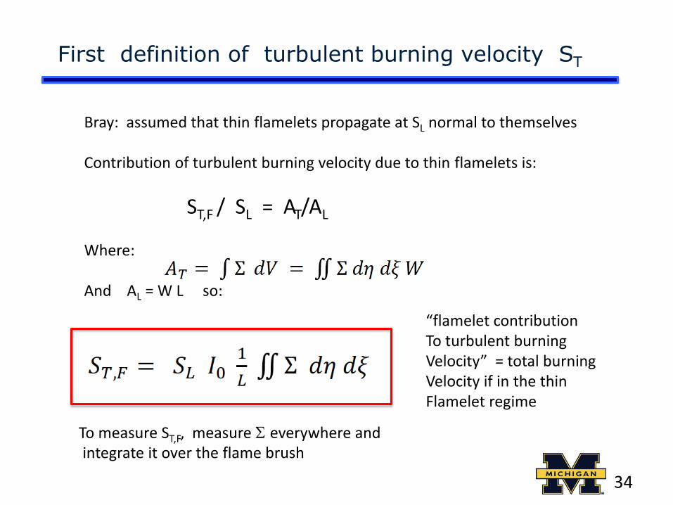
First definition of turbulent burning velocity ST
Bray: assumed that thin flamelets propagate at SL normal to themselves Contribution of turbulent burning velocity due to thin flamelets is:
ST,F / SL = AT/AL Where: And AL = W L so:
To measure ST,F, measure S everywhere and integrate it over the flame brush
“flamelet contribution To turbulent burning Velocity” = total burning Velocity if in the thin Flamelet regime
34

Second definition of turbulent burning velocity ST
ST,GC = Global consumption speed
= mass flow reactants / (density reactants) (area of =0.5 surface)
How to measure ST,GC ?
AT
Uo
ST
From the triangle drawn: sin = [d/2] [h2 + (d/2)2]-1/2 = ST/Uo
so:
ST = Uo (d/2) [h2 + (d/2)2]-1/2
large burning velocity ST = short flame
d
h
35

Suppose the flame wrinkles into two Bunsen cones, where is the cone half-angle. Similar to a Bunsen burner, the velocity normal to the wave must be SL, and the velocity normal to the cone is (U2-SL) sin , so equating these gives:
sin = SL / (U2-SL) and we define u’ = (U2-SL)
the cone has a radius of L/4 and height h, so: sin = (L/4)[ h2 + (L/4)2]-1/2
Equating these (and neglecting L/4 wrt h) yields: h = (u’ L) / (4 SL) Now the surface area of a cone is AT = p/4 (L/2)2 [(h/(L/2))2 + 1]1/2
and the area of the base of the cone is AL = p/4 (L/2)2 so:
L
Imagine an eddy of diameter L moving at a stationary laminar flame at speed SL; the eddy causes reactant to move at higher speed U2 at one place, and at lower speed U1 at another place
Predicted turbulent burning velocity see Kuo, Turb Combustion
Damkohler’s first concept - flame area AT determines burning velocity
36

Damkohler’s second concept - small eddies increase thermal diffusivity
Laminar flame speed
Turbulent flames propagate faster because turbulence diffuses the heat upstream to preheat the reactants faster than laminar flames
37
If eddies get inside preheat zone, we assume turbulent flames propagate faster because Eddies create larger thermal diffusivity T
turbulent diffusivity = velocity fluctuation times integral scale L; n = kinematic viscosity
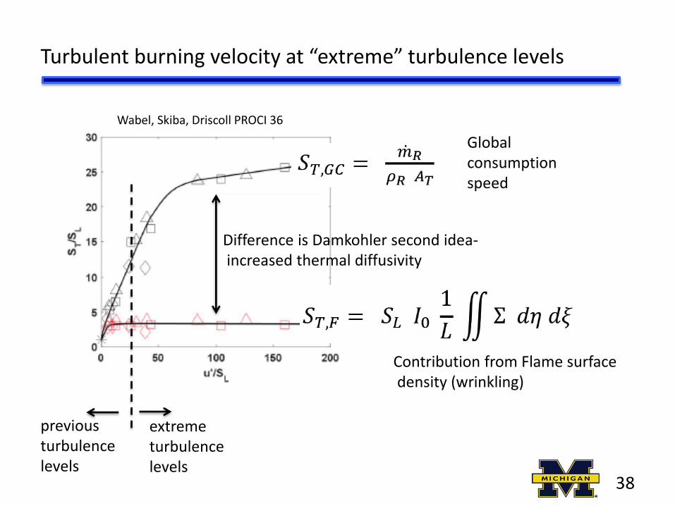
Turbulent burning velocity at “extreme” turbulence levels
Wabel, Skiba, Driscoll PROCI 36
Global consumption speed
Contribution from Flame surface density (wrinkling)
previous turbulence levels
extreme turbulence levels
Difference is Damkohler second idea- increased thermal diffusivity
38

Turbulent burning velocity – what do we know ?
1. Six major canonical geometries for premixed turbulent flames Bunsen, jet, low-swirl, V, spherical and swirl (Gas Turbine) 2. Burning velocity formula is different for each
3. Residence time (x/U) is important, bunsen flame tip becomes
more wrinkled than flame base, spherical flame gets more wrinkled in time 4. Reactant temperature, Reynolds number , Karlovitz number are important 5. Role of integral scale different for each geometry - can we correlate burning velocity with Reynolds number ReT ?
39

Turbulence Causes Faster Mixing = shorter flame length
Consider a non-premixed turbulent jet flame. Suppose we simplify by saying the fuel from the fuel tube - stays within the cylinder shown Air enters at an entrainment velocity Ue that is perpendicular to the cylinder wall
The length of the flame Lf is where the mass/sec of fuel, divided by the mass/sec of entrained air, equals the stoichiometric fuel-air ratio fs, which is 0.055 for methane
(H. Rehab, J Fluid Mech 345, 357 )
UA UA
Ue UA
Measurements show that the eddies rotate to cause the entrainment velocity Ue to be proportional to |c1UF-UA| (rF/rA)1/2
40
dF

If there is no co-flow (UA is zero) the turbulent eddies at the edge of the cylinder are created by the jet velocity UF so Ue is prop. to UF and the above reduces to:
Length of a jet flame with co-axial air
If there is strong co-flow air velocity, as in a gas turbine engine or rocket, then We neglect c1UF with respect to UA so the above reduces to:
Length of a jet flame with STRONG co-axial air
larger air velocity = shorter
Length of a jet flame with NO co-axial air
H2-O2 has large fs = short
Combine the above relations to eliminate Ue and solve for Lf to give :
41

Flame Liftoff and Blowout
Cases of interest: Fuel jet with no coflow air (flame base is partially premixed) Fuel jet with cold coflow air (base is partially premixed) Fuel jet w very hot coflow air (base is not a flame, is auto ignition) Fuel jet in hot cross flow (base is not a flame, is auto ignition) Fuel jet w swirled air (base is partially premixed) Cavity stabilized flame (premixed in shear layer at top of cavity)
DNS of Mizobuchi, Takeno red= rich premix, blue = lean premix green = non-premix PROCI 30, 2005
fuel air
Base of a lifted, jet flame that is initially non-premixed A lifted initially non-premixed jet flame
has a partially-premixed flame base
42

Definitions
Consider a fuel jet issuing into air (initially non-premixed) with UF = jet exit velocity Zs = stoichiometric mixture fraction = 0.055 for methane Us = axial velocity of gas along the stoichiometric contour; theory says: Us = constant - along the stoichiometric contour and this constant is = UF Zs Why ? See Kuo, conservation equations for mixture fraction (Z) and (u/UF) are identical for a jet flame Shear layer at fuel/air boundary is premixed upstream of lifted flame base Sbase = turbulent burning velocity – propagation speed of flame base against incoming reactants
43
Us
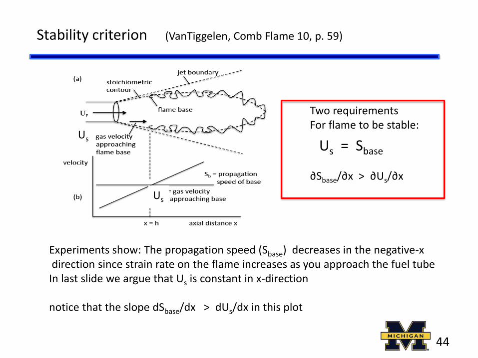
Stability criterion (VanTiggelen, Comb Flame 10, p. 59)
Us = Sbase
∂Sbase/∂x > ∂Us/∂x
Two requirements For flame to be stable:
Experiments show: The propagation speed (Sbase) decreases in the negative-x direction since strain rate on the flame increases as you approach the fuel tube In last slide we argue that Us is constant in x-direction notice that the slope dSbase/dx > dUs/dx in this plot
Us
Us
44

Flame normally is at location A where the two curves cross (Us = Sbase) Suppose the flame base was perturbed to move downstream to location B Since ∂Sbase/∂x > ∂Us/∂x, it follows that Sbase > Us at location B, this means That the flame will propagate upstream at speed (Sbase- Us) until it reaches A This flame is stable – a perturbation causes it to return to its original position !
Stability
45
A B
Us =
Us =

Scaling Analysis – for Liftoff height, Blowout velocity jet flame
we said: Us = Sbase and Us = UF Zs now we need a formula to estimate Sbase
Define Karlovitz number = nondim strain rate = (Us / x) / (SL /)
Assume: Sbase = SL [1 + Ka]-2 if Ka is large, Sbase is small
SL = laminar burning velocity, stoichiometric
Liftoff height h = x and we said: Us = UF Zs
Combine above, liftoff height is: h = {c1 UF / (SL2/ )} F
where function F is nearly constant
Larger jet velocity UF – higher liftoff height
46

There is no stoichiometric location downstream of x = Lf = mixing length to stoich. So when liftoff height (h) of flame base exceeds (Lf) – blowout occurs
h = Lf Lf = c2 dF Zs-1 from previous slide
h = c1 UF / (SL,02/ ) from previous slide
Combine these three equations and solve for UF
Blowout fuel velocity: UF = c3 dF / (SL
2/ ) / F
RESULT: Liftoff and blowout formulas agree with measurements ! Don’t make fuel injector diameter dF too small
Blowout velocity of a jet flame
47
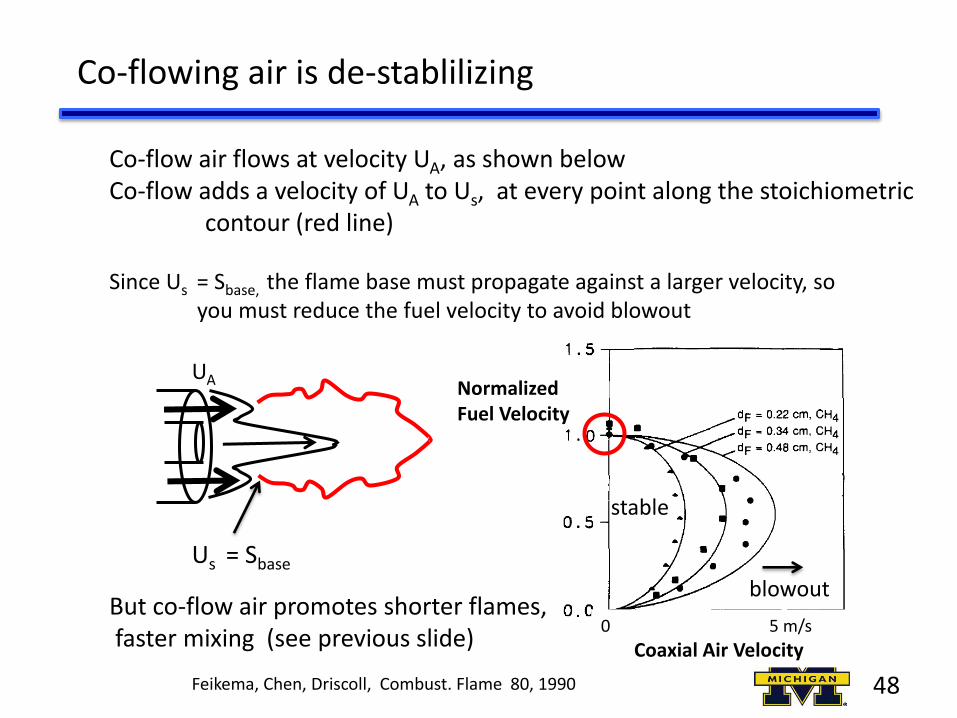
Co-flowing air is de-stablilizing
Co-flow air flows at velocity UA, as shown below Co-flow adds a velocity of UA to Us, at every point along the stoichiometric contour (red line) Since Us = Sbase, the flame base must propagate against a larger velocity, so you must reduce the fuel velocity to avoid blowout
Feikema, Chen, Driscoll, Combust. Flame 80, 1990
0 5 m/s
Coaxial Air Velocity
Normalized Fuel Velocity
Us = Sbase
UA
But co-flow air promotes shorter flames, faster mixing (see previous slide)
stable
blowout
48

Swirl is both STABILIZING and promotes faster mixing
Much larger fuel Velocity achieved with swirl
Feikema, Chen, Driscoll, Combust. Flame 80, 1990
Fuel Velocity m/s
0 50 Air Velocity m/s
stable
stable for zero swirl
200 0
so all gas turbine designs employ swirl swirl creates internal recirculation = low gas velocities
Uoo
blowout
49

Scramjets use wall cavities to stabilize the flame
Air enters across upper side of shear layer Fuel and hot products from recirculation zone enter across lower side of shear layer Flame exists along stochiometric contour
50

1. Liftoff height (h) where propagation speed (Sbase)= gas velocity Ug
2. Temperature at base is elevated due to hot recirculation zone 3. Too much cold fuel into RZ lowers temperatures, flame speed 4. When liftoff height h exceeds LRZ = “rich blowout” 5. Stable if ∂Sbase/∂x > ∂Us/∂x
Flame on the stochiometric contour
Fuel-air ratio
UA Air y
Us Fuel
Gas velocity decreases along stoichiometric contour
Flame propagation speed at flame base
x
Sbase,1
Sbase,2 Sbase,3
Us (x)
LRZ h2
h1
Increasing fuel mass flowrate
Blowout of cavity-stabilized flame – same ideas as before
51

Base of a lifted flame is a “triple flame” How fast does a triple flame propagate ?
rich premixed
flame
lean premixed flame
non-premixed flame
fuel air
52

References - Flame blowout
Vanquickenborne L, van Tiggelen A. Combust Flame 1966;10, p. 59 Kalghatgi G. Blowout stability limits. Combust Sci Technol 1981; 26, p. 233. Kalghatgi G. Liftoff heights of jet diffusion flames. Combust Sci Technol 41: p.17. Brown C, Lyons K Studies on lifted jet flames in coflow. Flow Turb Comb 1999, p. 249. Driscoll, J. F. Correlation and Analysis of Blowout Limits of Flames in High-Speed Airflows, J. Propulsion Power 21, 6,1035, 2005 Mizobuchi, Takeno, PROCI 30, p. 611, 2005
53