turboelectric aircraft drive key performance parameters
TRANSCRIPT
Advanced Air Vehicles Program
Advanced Transport Technologies Project
Turboelectric Aircraft Drive Key
Performance Parameters and Functional
Requirements
Ralph H. Jansen, Dr. Gerald V. Brown and James L. Felder
NASA Glenn Research Center, Cleveland, Ohio, 44135
and
Dr. Kirsten P. Duffy
University of Toledo, Toledo, Ohio, 43606
Advanced Air Vehicles Program
Advanced Transport Technologies Project
Introduction
• There is substantial interest in the investigation of improvements to
aircraft by the introduction of electrical components into the propulsion
system.
• In the case of a turboelectric aircraft the electrical systems can provide
unmatched flexibility in coupling the power generation turbine(s) to the
fan propulsors.
• This flexibility can result in reduced noise, emissions, and fuel burn.
• However, the greatly expanded electrical system introduces weight and
efficiency burdens that oppose these benefits.
• A break-even analysis is presented here to determine the electrical
power system performance level necessary to achieve a net benefit at
the aircraft level. 2
Advanced Air Vehicles Program
Advanced Transport Technologies Project
Approach
• In order to conduct the break-even analysis we will define the key
performance parameters, the key functional requirements, and the
electrical power system boundary.
• Then we will formulate range equations for a base aircraft and a
turboelectric version of that aircraft.
• Next we will find the range of possible benefits from a literature survey
and calculate the weight and fuel burn costs.
• Finally, we find the break-even point by setting the ranges of the two
aircraft types equal and using the same initial weight, operating empty
weight, and payload weight and implicitly solving for the electric drive
specific power and efficiency.
• The resulting parametric curves combined with the functional
requirements will be used as input requirements for the electrical power
system.
3
Advanced Air Vehicles Program
Advanced Transport Technologies Project
Drive System Selected for Evaluation
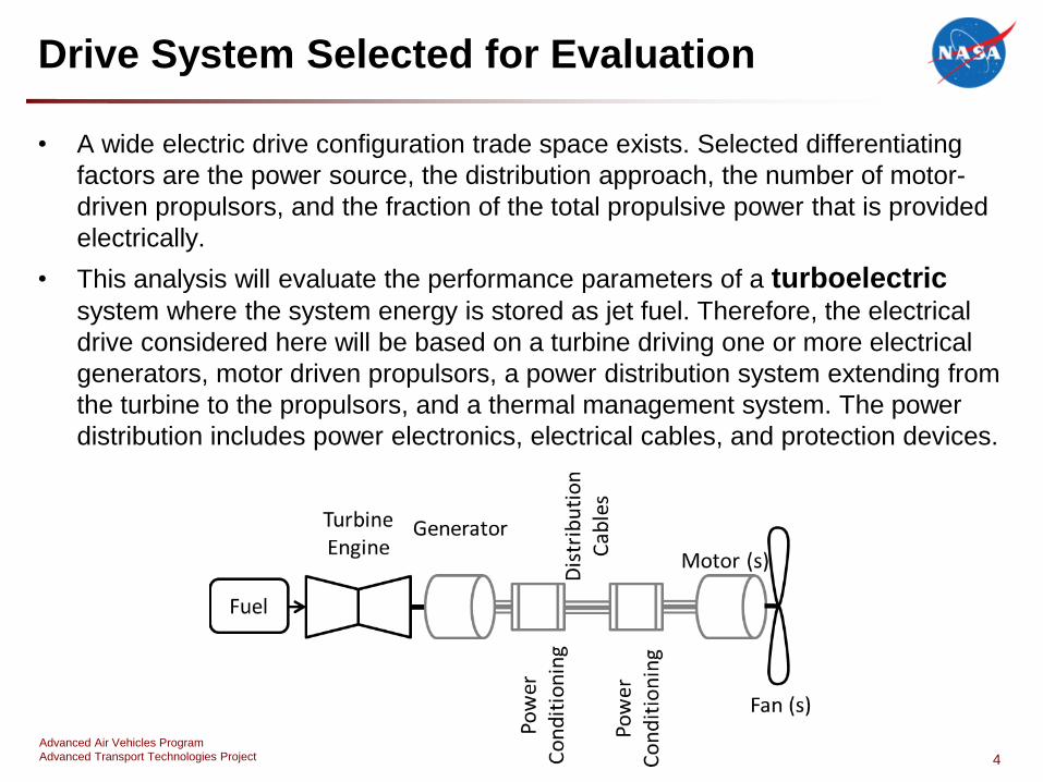
• A wide electric drive configuration trade space exists. Selected differentiating
factors are the power source, the distribution approach, the number of motor-
driven propulsors, and the fraction of the total propulsive power that is provided
electrically.
• This analysis will evaluate the performance parameters of a turboelectricsystem where the system energy is stored as jet fuel. Therefore, the electrical
drive considered here will be based on a turbine driving one or more electrical
generators, motor driven propulsors, a power distribution system extending from
the turbine to the propulsors, and a thermal management system. The power
distribution includes power electronics, electrical cables, and protection devices.
4
Advanced Air Vehicles Program
Advanced Transport Technologies Project
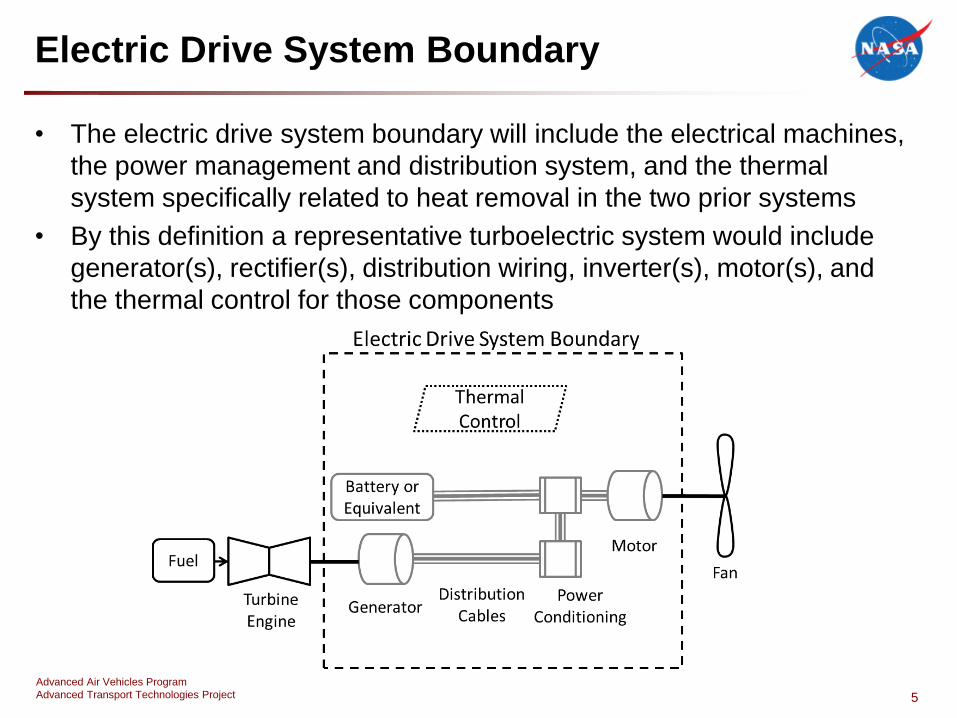
Electric Drive System Boundary
• The electric drive system boundary will include the electrical machines,
the power management and distribution system, and the thermal
system specifically related to heat removal in the two prior systems
• By this definition a representative turboelectric system would include
generator(s), rectifier(s), distribution wiring, inverter(s), motor(s), and
the thermal control for those components
5
Advanced Air Vehicles Program
Advanced Transport Technologies Project
Key Performance Parameters
• Specific power (SpED) and efficiency (ED) are proposed as
the two KPPs of the electric drive system in a turboelectric
aircraft.
• Specific power is the ratio of the rated power to the mass of
the power system.
• Efficiency is the ratio of the output power to the input power
of the power system.
• These quantities will be used to describe electrical power
system performance and establish levels of performance
necessary for successful aircraft.
6
Advanced Air Vehicles Program
Advanced Transport Technologies Project
Key Functional Requirements
• Distinct from the KPPs are the functional requirements of the electric
drive system. Two of the crucial functional requirements for a
turboelectric aircraft power system are independent speed and power
control as well as redundancy and reliability levels.
• Independent speed and power control of individual fan propulsors is
required in most proposed electric aircraft drive configurations and may
enable configurations allowing
– fan and turbine speed decoupling allowing optimal operation throughout the flight
regime
– yaw control through differential thrust
– the ability to provide high-velocity wing blowing with controlled thrust
– noise reduction strategies.
• Redundancy and reliability requirements are not yet well defined for an
electric aircraft drive system; however, it is clear that the system must at
least meet the safety standards that current aircraft propulsion systems
meet.
7
Advanced Air Vehicles Program
Advanced Transport Technologies Project
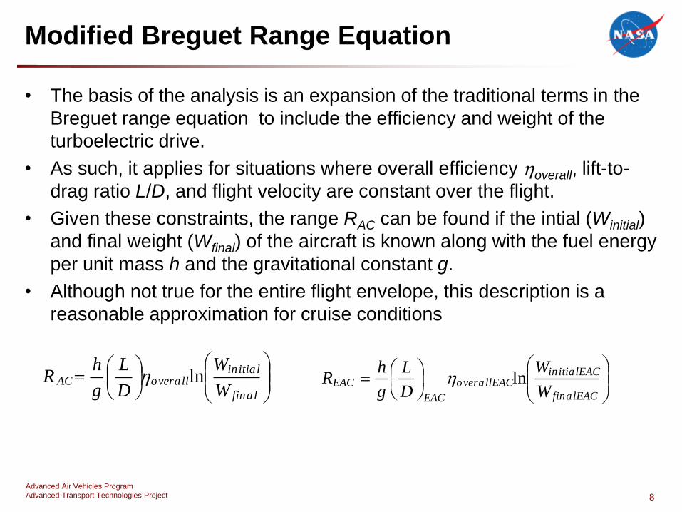
Modified Breguet Range Equation
• The basis of the analysis is an expansion of the traditional terms in the
Breguet range equation to include the efficiency and weight of the
turboelectric drive.
• As such, it applies for situations where overall efficiency overall, lift-to-
drag ratio L/D, and flight velocity are constant over the flight.
• Given these constraints, the range RAC can be found if the intial (Winitial)
and final weight (Wfinal) of the aircraft is known along with the fuel energy
per unit mass h and the gravitational constant g.
• Although not true for the entire flight envelope, this description is a
reasonable approximation for cruise conditions
8
final
initialoverallAC
W
W
D
L
g
hR ln
finalEAC
initialEACoverallEAC
EAC
EACW
W
D
L
g
hR ln
Advanced Air Vehicles Program
Advanced Transport Technologies Project
Modified Breguet Range Equation
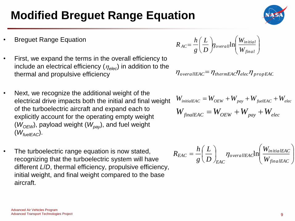
• Breguet Range Equation
• First, we expand the terms in the overall efficiency to
include an electrical efficiency (elec) in addition to the
thermal and propulsive efficiency
• Next, we recognize the additional weight of the
electrical drive impacts both the initial and final weight
of the turboelectric aircraft and expand each to
explicitly account for the operating empty weight
(WOEW), payload weight (Wpay), and fuel weight
(WfuelEAC).
• The turboelectric range equation is now stated,
recognizing that the turboelectric system will have
different L/D, thermal efficiency, propulsive efficiency,
initial weight, and final weight compared to the base
aircraft.
9
final
initialoverallAC
W
W
D
L
g
hR ln
propEACelecthermEACoverallEAC
elecfuelEACpayOEWinitialEAC WWWWW
elecpayOEWfinalEAC WWWW
finalEAC
initialEACoverallEAC
EAC
EACW
W
D
L
g
hR ln
Advanced Air Vehicles Program
Advanced Transport Technologies Project
Fuel Burn Benefit Ranges from Literature
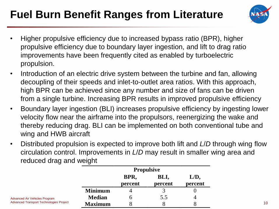
• Higher propulsive efficiency due to increased bypass ratio (BPR), higher
propulsive efficiency due to boundary layer ingestion, and lift to drag ratio
improvements have been frequently cited as enabled by turboelectric
propulsion.
• Introduction of an electric drive system between the turbine and fan, allowing
decoupling of their speeds and inlet-to-outlet area ratios. With this approach,
high BPR can be achieved since any number and size of fans can be driven
from a single turbine. Increasing BPR results in improved propulsive efficiency
• Boundary layer ingestion (BLI) increases propulsive efficiency by ingesting lower
velocity flow near the airframe into the propulsors, reenergizing the wake and
thereby reducing drag. BLI can be implemented on both conventional tube and
wing and HWB aircraft
• Distributed propulsion is expected to improve both lift and L/D through wing flow
circulation control. Improvements in L/D may result in smaller wing area and
reduced drag and weight
10
Propulsive
L/D,
percent
BPR,
percent
BLI,
percent
Minimum 4 3 0
Median 6 5.5 4
Maximum 8 8 8
Advanced Air Vehicles Program
Advanced Transport Technologies Project
Weight Impacts as a function of KPPs
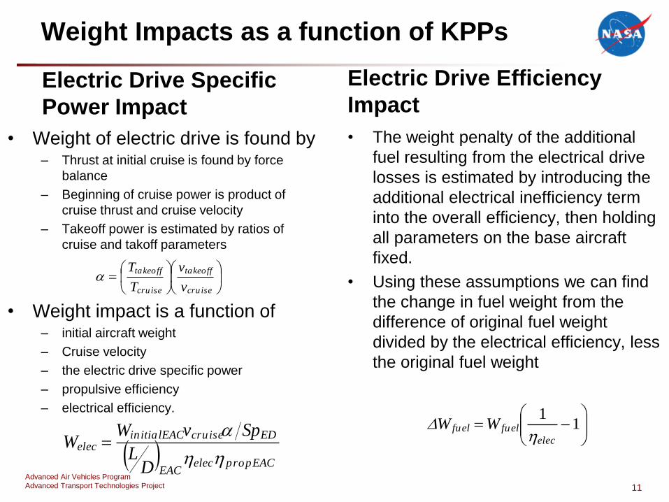
Electric Drive Specific
Power Impact
• Weight of electric drive is found by– Thrust at initial cruise is found by force
balance
– Beginning of cruise power is product of
cruise thrust and cruise velocity
– Takeoff power is estimated by ratios of
cruise and takoff parameters
• Weight impact is a function of– initial aircraft weight
– Cruise velocity
– the electric drive specific power
– propulsive efficiency
– electrical efficiency.
Electric Drive Efficiency
Impact
• The weight penalty of the additional
fuel resulting from the electrical drive
losses is estimated by introducing the
additional electrical inefficiency term
into the overall efficiency, then holding
all parameters on the base aircraft
fixed.
• Using these assumptions we can find
the change in fuel weight from the
difference of original fuel weight
divided by the electrical efficiency, less
the original fuel weight
11
propEACelecEAC
EDcruiseinitialEACelec
DL
SpvWW
cruise
takeoff
cruise
takeoff
v
v
T
T
1
1
elec
fuelfuel WW
Advanced Air Vehicles Program
Advanced Transport Technologies Project
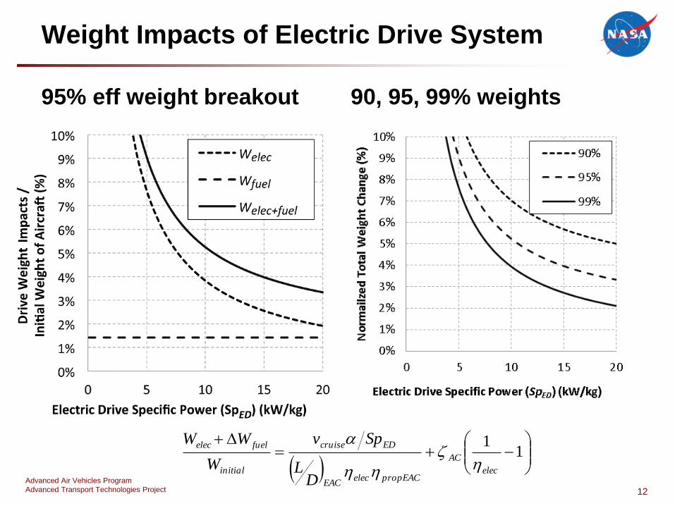
Weight Impacts of Electric Drive System
95% eff weight breakout 90, 95, 99% weights
12
1
1
elec
AC
propEACelecEAC
EDcruise
initial
fuelelec
DL
Spv
W
WW
Advanced Air Vehicles Program
Advanced Transport Technologies Project
Fuel Burn Impact of Electric Drive
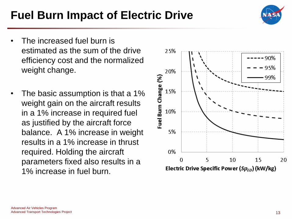
• The increased fuel burn is
estimated as the sum of the drive
efficiency cost and the normalized
weight change.
• The basic assumption is that a 1%
weight gain on the aircraft results
in a 1% increase in required fuel
as justified by the aircraft force
balance. A 1% increase in weight
results in a 1% increase in thrust
required. Holding the aircraft
parameters fixed also results in a
1% increase in fuel burn.
13

Advanced Air Vehicles Program
Advanced Transport Technologies Project
Breakeven Analysis
• The break-even analysis determines the electric drive specific power and
efficiency where the costs of adding the drive exactly equal the benefits.
• Base aircraft and turboelectric aircraft performance parameters are constant in
this analysis.
• The breakeven equation is found by
– First, the range expressions of the base aircraft and the turboelectric aircraft are
equated
– Then the common terms are canceled and the efficiency terms expanded
– Next, the terms are arranged so the benefits are on left and costs are on the right with
expanded weight terms
– Finally, the electrical drive weight as function of specific power, and the aircraft
parameters are included
• Breakeven lines are found be implicitly solving equation balancing the costs and
benefits across a range of specific powers at a expected benefit level
14
𝐿𝐷𝐿𝐷 𝐸𝐴𝐶𝑎𝑒𝑟𝑜𝑏𝑒𝑛𝑒𝑓𝑖𝑡𝑠
𝜂𝑡ℎ𝑒𝑟𝑚𝜂𝑡ℎ𝑒𝑟𝑚𝐸𝐴𝐶
𝜂𝑝𝑟𝑜𝑝
𝜂𝑝𝑟𝑜𝑝𝐸𝐴𝐶𝑝𝑟𝑜𝑝𝑢𝑙𝑠𝑖𝑣𝑒 𝑏𝑒𝑛𝑒𝑓𝑖𝑡𝑠
= 𝜂𝑒𝑙𝑒𝑐𝑒𝑙𝑒𝑐𝑡𝑟𝑖𝑐𝑎𝑙𝑒𝑓𝑓𝑖𝑐𝑖𝑒𝑛𝑐𝑦𝑐𝑜𝑠𝑡
ln𝑊𝑖𝑛𝑖𝑡𝑖𝑎𝑙
𝑊𝑂𝐸𝑊 +𝑊𝑝𝑎𝑦 +𝑊𝑖𝑛𝑖𝑡𝑖𝑎𝑙𝑣𝑐𝑟𝑢𝑖𝑠𝑒 α𝐿𝐷 𝐸𝐴𝐶𝜂𝑝𝑟𝑜𝑝𝐸𝐴𝐶
1𝜂𝑒𝑙𝑒𝑐𝑆𝑝𝐸𝐷
ln𝑊𝑖𝑛𝑖𝑡𝑖𝑎𝑙𝑊𝑂𝐸𝑊 +𝑊𝑝𝑎𝑦
𝑤𝑒𝑖𝑔ℎ𝑡 𝑐𝑜𝑠𝑡 𝑓𝑟𝑜𝑚 𝑠𝑝𝑒𝑐𝑖𝑓𝑖𝑐 𝑝𝑜𝑤𝑒𝑟 𝑎𝑛𝑑 𝑒𝑓𝑓𝑖𝑐𝑖𝑒𝑛𝑐𝑦
Advanced Air Vehicles Program
Advanced Transport Technologies Project
Breakeven Results
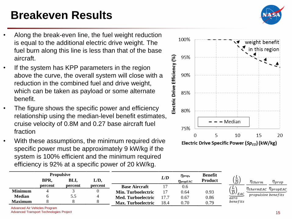
• Along the break-even line, the fuel weight reduction
is equal to the additional electric drive weight. The
fuel burn along this line is less than that of the base
aircraft.
• If the system has KPP parameters in the region
above the curve, the overall system will close with a
reduction in the combined fuel and drive weight,
which can be taken as payload or some alternate
benefit.
• The figure shows the specific power and efficiency
relationship using the median-level benefit estimates,
cruise velocity of 0.8M and 0.27 base aircraft fuel
fraction
• With these assumptions, the minimum required drive
specific power must be approximately 9 kW/kg if the
system is 100% efficient and the minimum required
efficiency is 92% at a specific power of 20 kW/kg.
15
Propulsive
L/D,
percent
BPR,
percent
BLI,
percent
Minimum 4 3 0
Median 6 5.5 4
Maximum 8 8 8
L/D prop,
propEAC
Benefit
Product
Base Aircraft 17 0.6
Min. Turboelectric 17 0.64 0.93
Med. Turboelectric 17.7 0.67 0.86
Max. Turboelectric 18.4 0.70 0.79
𝐿𝐷𝐿𝐷 𝐸𝐴𝐶𝑎𝑒𝑟𝑜𝑏𝑒𝑛𝑒𝑓𝑖𝑡𝑠
𝜂𝑡ℎ𝑒𝑟𝑚𝜂𝑡ℎ𝑒𝑟𝑚𝐸𝐴𝐶
𝜂𝑝𝑟𝑜𝑝
𝜂𝑝𝑟𝑜𝑝𝐸𝐴𝐶𝑝𝑟𝑜𝑝𝑢𝑙𝑠𝑖𝑣𝑒 𝑏𝑒𝑛𝑒𝑓𝑖𝑡𝑠
Advanced Air Vehicles Program
Advanced Transport Technologies Project
Breakeven Results
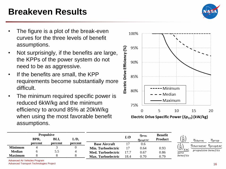
• The figure is a plot of the break-even
curves for the three levels of benefit
assumptions.
• Not surprisingly, if the benefits are large,
the KPPs of the power system do not
need to be as aggressive.
• If the benefits are small, the KPP
requirements become substantially more
difficult.
• The minimum required specific power is
reduced 6kW/kg and the minimum
efficiency to around 85% at 20kW/kg
when using the most favorable benefit
assumptions.
16
Propulsive
L/D,
percent
BPR,
percent
BLI,
percent
Minimum 4 3 0
Median 6 5.5 4
Maximum 8 8 8
L/D prop,
propEAC
Benefit
Product
Base Aircraft 17 0.6
Min. Turboelectric 17 0.64 0.93
Med. Turboelectric 17.7 0.67 0.86
Max. Turboelectric 18.4 0.70 0.79
𝐿𝐷𝐿𝐷 𝐸𝐴𝐶𝑎𝑒𝑟𝑜𝑏𝑒𝑛𝑒𝑓𝑖𝑡𝑠
𝜂𝑡ℎ𝑒𝑟𝑚𝜂𝑡ℎ𝑒𝑟𝑚𝐸𝐴𝐶
𝜂𝑝𝑟𝑜𝑝
𝜂𝑝𝑟𝑜𝑝𝐸𝐴𝐶𝑝𝑟𝑜𝑝𝑢𝑙𝑠𝑖𝑣𝑒 𝑏𝑒𝑛𝑒𝑓𝑖𝑡𝑠

Advanced Air Vehicles Program
Advanced Transport Technologies Project
Conclusions
• Specific power and efficiency are proposed as two key performance parameters for the
electric drive system of a turboelectric aircraft.
• The costs were associated with the proposed KPPs. Analysis of the costs leads to the
conclusion that below a specific power of approximately 5 kW/kg, the specific power is the
dominant cost, whereas above that level the efficiency becomes dominant. Additionally it
is noted that the fuel burn cost can never be less than the inefficiency of the electric drive
system.
• A breakeven equation was developed by using range equations for a base air craft and a
turboelectric aircraft. It was developed in a form which separated the costs and benefits of
the system.
• KPP break-even weight curves were found for the minimum, median, and maximum
turboelectric benefit cases and the region of power system performance that will result in a
net weight benefit is shown.
• Further work will need to be done to define the net fuel burn benefit region and consider
hybrid or all electric configurations.
17