turbo® refrigerating htd and hf chillers - vogtice.com · installation review : a checklist ......
TRANSCRIPT
TURBO® Refrigerating
HTD and HF Chillers
Manual Part Number 12A4171M15
Service Manual $5000 USD
NOTICE
This manual is the property of the owner of this particular Vogt Ice,
LLC machine.
Model #____________________ Serial #____________________
It is to be left on the premises with this machine at all times. After
start-up, it should be stored in a safe place where it can be readily
available when needed for future reference in maintaining
troubleshooting or servicing.
Failure to comply with this notice will result in unnecessary
inconvenience and possible additional expenses.
This manual is intended as an informational tool for the installation,
operation, maintenance, troubleshooting, and servicing of this
equipment. If an existing situation calls for additional information not
found herein, we suggest that you contact your distributor first. If
further assistance or information is needed, please feel free to contact
the factory at 502-635-3000 or FAX at 502-635-3024.
IMPORTANT: The Warranty Registration/Start-Up Report found in the
front of this manual is to be completed and returned to the factory
promptly after the official start-up.
Please return to: Vogt Ice, LLC
1000 W. Ormsby Ave.
Suite 19
Louisville, KY 40210

Vogt Ice, LLC
1000 W. Ormsby Ave, Ste. 19
Louisville, KY 40210
Phone: 502-635-3235
Fax: 502-635-3024
Vogt Order No.:
THIS FORM MUST BE SENT TO VOGT TO
ACTIVATE WARRANTY
Warranty Registration / Start-Up Form - HTD and HF Series Chillers
Model Number: Serial Number:
This form must be filled out completely and signed by the customer in order to assure acceptance by Vogt
Date of Start-Up: Form Completed By:
Distributor
Company Name: Phone:
Address: City: State: Zip:
Service Company
Company Name: Phone:
Address: City: State: Zip:
Customer (Location of Equipment)
Company Name: Phone:
Address: City: State: Zip:
PRE-OPERATION CHECK OPERATION CHECK
Machine room suitable 40°F min., 100°F max.
Chiller securely mounted to reservoir (if supplied)
Chiller (or reservoir) securely mounted to floor or base
Water supply and drains connected properly
All accessory components (oil traps, surge drums, valve
packages, etc.) are properly installed
Field connections to chiller per data sheet
Field piping weld joints cleaned, passivated and leak free
Evaporator plates properly evacuated and charged with
refrigerant
Relief devices properly installed and vented to safe location
Instruction manual and warranty certificate left on-site
Name of person left with: _________________________
Evaporator plates clean
Frame, panel interior, water distribution pan, and headers clean
Water flow across all plates providing complete wetting of plate surfaces
Suction pressure at suction header on chiller per data sheet
Entering water temperature at chiller per data sheet
Leaving water temperature at chiller per data sheet
Inlet water pressure between 5 PSIG and 100 PSIG
Ambient temperature __________ °F
Comments:
Technician Signature: End User Signature: I certify that I have performed all of the above procedures

Vogt Ice, LLC
Manufacturers of Quality Ice Machines
Located in Louisville, Kentucky since 1880
Sales – 1-800-959-8468
Service – 1-502-635-3000
Parts – Your Local Distributor
Call your local distributor first for all of your parts and service needs
i
Table of Contents
HTD and HF Series Chillers
Chapter 1 : Introduction ......................................................................................................................................... 1-1
A Brief History of Our Company ......................................................................................................................... 1-1
TURBO® Refrigeration ........................................................................................................................................ 1-1
Fluid Heat Exchangers ........................................................................................................................................ 1-1
HTD Series........................................................................................................................................................... 1-1
HF Series ............................................................................................................................................................. 1-1
Applications ........................................................................................................................................................ 1-2
Models ................................................................................................................................................................ 1-2
Refrigerants and Refrigerant Feeds .................................................................................................................... 1-2
Associated Equipment ........................................................................................................................................ 1-2
Modular C-Line Ice Makers (MCL) .................................................................................................................. 1-2
Modular Hot Gas Ice Generators (MHG) ........................................................................................................ 1-2
Ice Storage Systems ........................................................................................................................................ 1-3
Block Press ...................................................................................................................................................... 1-3
Special Applications ........................................................................................................................................ 1-3
Vogt SuperCare Customer Service ..................................................................................................................... 1-4
Important Safety Notice ..................................................................................................................................... 1-4
Safety Symbols and What They Mean ................................................................................................................ 1-4
Chapter 2 : Receipt of Your Chiller ......................................................................................................................... 2-1
Inspection ........................................................................................................................................................... 2-1
Delivery Inspection Checklist .......................................................................................................................... 2-1
Storage (Prior to Installation and Start-Up) ....................................................................................................... 2-1
Chapter 3 : Installation of HTD and HF Series Chillers ............................................................................................ 3-1
To Help You Get Started ..................................................................................................................................... 3-1
Figure 3-1 – Typical Chiller Orientation .............................................................................................................. 3-2
Recommended Service and Cleaning Clearances ............................................................................................... 3-2
Tools Required for Installation ........................................................................................................................... 3-2
Equipment Rigging Instructions .......................................................................................................................... 3-3
Figure 3-2 – Typical Chiller Lifting Orientation ................................................................................................... 3-3
Hoisting or Moving ............................................................................................................................................. 3-4
Table 3-1 – Shipping and Operating Weights for 48” HTD Series Chillers .......................................................... 3-4
Table 3-2 – Shipping and Operating Weights for 72” HTD Series Chillers .......................................................... 3-5
Table 3-3 – Shipping and Operating Weights for 96” HTD Chiller Models ......................................................... 3-6
Table 3-4 – Shipping and Operating Weights for uHTD Series Chiller Models ................................................... 3-7

ii
Table 3-5 – Shipping and Operating Weights for 144” HF Series Chiller Models ............................................... 3-7
Table 3-6 – Chiller Reservoir Specifications........................................................................................................ 3-8
Outdoor Installation ........................................................................................................................................... 3-8
Raised Curbing .................................................................................................................................................... 3-8
Elevated Installation ........................................................................................................................................... 3-9
Figure 3-3 – Elevated Installation ....................................................................................................................... 3-9
Mounting and Leveling ....................................................................................................................................... 3-9
Access, Service, Air Space ................................................................................................................................... 3-9
Water System ................................................................................................................................................... 3-10
General Requirements.................................................................................................................................. 3-10
Water Supply and Drain Connections .......................................................................................................... 3-10
Water Quality and Treatment ...................................................................................................................... 3-10
Water Temperature ...................................................................................................................................... 3-11
Water Distribution Header ........................................................................................................................... 3-11
Water Distribution Pan ................................................................................................................................. 3-11
Water Distribution Pan Filter ....................................................................................................................... 3-12
Insulation ...................................................................................................................................................... 3-12
Electrical Connections ...................................................................................................................................... 3-12
Refrigerant Connections ................................................................................................................................... 3-12
Leak Test of Field Installed Refrigeration Piping .............................................................................................. 3-13
Evacuating the System ..................................................................................................................................... 3-14
Charging the System with Refrigerant.............................................................................................................. 3-15
Table 3-7 – Evaporator Plate Operating Charges ............................................................................................. 3-15
Relief Devices.................................................................................................................................................... 3-16
Table 3-8 – Maximum Equivalent Length for Relief Valve Discharge Piping .................................................... 3-16
Post Installation Clean Up ................................................................................................................................ 3-17
Rule #1. Ship it Clean ................................................................................................................................... 3-17
Rule #2. Install it Clean ................................................................................................................................ 3-17
Rule #3. Keep it Clean .................................................................................................................................. 3-17
Chiller Protection during Installation ........................................................................................................... 3-17
Weld Zone Clean Up ..................................................................................................................................... 3-18
Other Areas................................................................................................................................................... 3-18
Final Cleaning................................................................................................................................................ 3-18
Installation Review : A Checklist ....................................................................................................................... 3-19
iii
Chapter 4 : Operation ............................................................................................................................................. 4-1
General Information ........................................................................................................................................... 4-1
Flooded System .................................................................................................................................................. 4-2
Principle of Operation .................................................................................................................................... 4-2
Surge Drum ..................................................................................................................................................... 4-2
Oil Accumulator Drum (Oil Pot) ...................................................................................................................... 4-2
Liquid Recirculated System................................................................................................................................. 4-3
Principle of Operation .................................................................................................................................... 4-3
Liquid Recirculator .......................................................................................................................................... 4-3
Oil Accumulator Drum (Oil Pot) ...................................................................................................................... 4-3
Direct Expansion (DX) System ............................................................................................................................ 4-4
Principle of Operation .................................................................................................................................... 4-4
TXV and Refrigerant Distributors.................................................................................................................... 4-4
Glycol System ..................................................................................................................................................... 4-5
Principle of Operation .................................................................................................................................... 4-5
Glycol Chiller Shutdown ................................................................................................................................. 4-5
Glycol Temperature ........................................................................................................................................ 4-5
Glycol Flow ..................................................................................................................................................... 4-5
Glycol Pressure ............................................................................................................................................... 4-5
Chapter 5 : Troubleshooting ................................................................................................................................... 5-1
Chapter 6 : Maintenance ........................................................................................................................................ 6-1
Daily Inspections ................................................................................................................................................. 6-1
Weekly Inspections ............................................................................................................................................. 6-1
After First Ten and Fifty Hours of Operation ...................................................................................................... 6-2
Water Scale Build-Up .......................................................................................................................................... 6-2
Scale Formation on Evaporator Plates ............................................................................................................... 6-2
Scale and Solids in Chiller Sump ......................................................................................................................... 6-2
Scaling of Condensers and Cooling Towers ........................................................................................................ 6-3
Stainless Steel Surface Cleaning ......................................................................................................................... 6-3
Helpful Hints ....................................................................................................................................................... 6-3
Preventive Maintenance Form ........................................................................................................................... 6-4
Chapter 7 : Optional Accessories ............................................................................................................................ 7-1
Option 1 : Water Level and Flow Control Package ............................................................................................. 7-1
Option 2 : Surge Drum for Flooded Machines .................................................................................................... 7-1
Figure 7-1 – Typical Surge Drum ......................................................................................................................... 7-2
Option 3 : Oil Accumulator Drum or Oil Pot for Flooded Machines................................................................... 7-2
Option 4 : High Pressure Liquid Line Valve Package for Flooded Machines ...................................................... 7-3
iv
Option 5 : Suction Line Valve Package with Pressure Regulator for Flooded Machines .................................... 7-3
Option 7 : Refrigerant Level Control Package for Flooded Machines ................................................................ 7-4
Option 8 : Liquid Line Valve Package for Liquid Recirculated Machines ............................................................ 7-4
Option 9 : Suction Line Valve Package for Liquid Recirculated Machines .......................................................... 7-4
Option 10 : Direct Expansion Liquid Feed Group ............................................................................................... 7-5
Option 11 : Dual Refrigerant Feed Circuits ......................................................................................................... 7-5
Option 12 : Low Carbon Content (304L) Stainless Steel Construction ............................................................... 7-5
Chapter 8 : Index .................................................................................................................................................... 8-1

1-1
Chapter 1 : Introduction
A Brief History of Our Company
The Henry Vogt Machine Co. was founded as a small machine shop in Louisville, Kentucky in 1880. In 1938, Vogt
built the first Tube-Ice® machine and revolutionized the ice-making industry. Our first “sized-ice” machine quickly
replaced the old can-ice plants, which required much hard labor and large amounts of floor space for freezing,
cutting, and crushing ice by hand.
The Henry Vogt Machine Co. eventually sold its Tube-Ice® division to Vogt Ice, LLC. Since that time, Vogt Ice, LLC
acquired Turbo Refrigeration® in 1989, a company which has become a market leader of plate ice equipment.
With the strong history of these two brands, Vogt Ice, LLC carries on the tradition as one of the world’s leading
producers of ice-making equipment.
TURBO® Refrigeration
In 1989, Vogt acquired TURBO® which had been producing a line of fluid chillers since 1984, as well as icemakers
and ice generators for the ice industry since 1960. Today, Vogt continues the tradition of building TURBO®
equipment under the Vogt name. The chillers described in this manual are part of a family of products designed
specifically for the industrial market for a variety of cooling needs.
Fluid Heat Exchangers
HTD and HF series heat exchangers are designed to instantaneously chill fluids falling over vertical stainless steel
plates in a thin falling film. Because of method of chilling the liquid heat exchangers are often referred to as falling
film chillers.
HTD Series
HTD stands for High Temperature Difference. Fluids are chilled or heated over large temperature differences,
ranging from 5°F to 60°F in a single pass using R-404A, ammonia or glycol as the refrigerant inside the plate.
Systems are available in direct expansion (DX), flooded and recirculated models. Flow rates are available over a
wide range but are typical considered relatively low. Higher flow rates can be obtained with HF chillers.
HF Series
HF stands for High Flow. Fluids are chilled over narrow temperature differences, ranging from 1°F to 2°F. The
plate’s long narrow geometry enables high fluid flow over the plate. Ammonia, R-404A and glycol are all available
for use in direct expansion, flooded and recirculated systems.

1-2
Applications
HTD/HF chillers are suitable for a variety of applications including:
• Food
• Beverage
• Chemical
• Manufacturing
Models
A number of standard and special chiller plates are available in a variety of configurations to meet many
applications. Standard plate sizes include:
• 48” x 60”
• 72” x 60”
• 96” x 60”
• 144” x 24”
Refrigerants and Refrigerant Feeds
Chillers are available in R-404A, ammonia, and glycol with direct expansion (DX), flooded, and recirculated
refrigerant feed.
Associated Equipment
Modular C-Line Ice Makers (MCL)
Packaged ice applications require a dry sub-cooled ice to avoid the formation of large blocks of ice in the product
bags. To meet this need, Vogt produces the MCL icemaker, which uses a water defrost to produce 15 tons per day
of ½” thick ice per unit using ammonia. Multiple units can be purchased and installed side-by-side to achieve the
desired ice capacity for the system installation.
Modular Hot Gas Ice Generators (MHG)
In industrial applications where ice with a dry surface is not required, Vogt offers the MHG icemaker, which uses
a hot gas defrost to produce 26 tons per day of ½” thick ice per unit using ammonia. As with the MCL, multiple
units can be installed side-by-side to achieve the desired ice capacity for the installation.
Typical Applications:
• Produce and food processing
• Concrete icing
• Ingredient icing (bakeries)
• Fish and poultry icing
• Chemical and dye processes
• Emergency cooling loads
• Ice slurries
• Catering trucks
• Salad bars or display ice

1-3
Ice Storage Systems
TURBO® rakes and storage bins were introduced in 1967. Today, Vogt offers four sizes ranging in capacity from 49
tons up to 87 tons of ice storage. These rakes have been used in USDA inspected installations.
The entire load and unload sequence is automatic and does not require the operator to be in contact with the ice
or any moving parts in the ice storage system.
The continuous presence of an operator is not required although it is recommended. At the end of the day, the
bin is empty (on a design day). The bin refills overnight and is full when personnel return to work.
NOTE: All controls are adjustable to allow the load or unload rate to match the customer’s production and/or
delivery requirements.
USDA Design
All Vogt ice storage systems are designed to meet USDA guidelines and meet rugged industrial standards which
make them the most reliable in the industry. Each system is designed to make the loading and unloading of the
ice storage system as safe and simple as possible. Regardless of size, all of the ice storage systems operate in
basically the same simple yet reliable manner.
Block Press
Vogt offers another feature to make optimum profits from your ice production. Instead of throwing away the
snow produced by the breaker bar, ice sizer, screw conveyors, or other handling devices, install a BP360 block
press. This block press converts the snow into ten or fifty-five pound blocks of ice.
Introduced in 1977, the block press is a completely automatic, hydraulic powered unit capable of up to 360 ten
pound blocks per hour.
The block press is available with a block bagger attachment, which means:
• Eliminates handling until the block is in the bag
• A better product
• Higher profits
Special Applications
Vogt Ice, LLC is in the business of supplying equipment to meet the needs of the customer. If you have an
application or a need that is not discussed here, contact:
Vogt Ice, LLC
1000 W. Ormsby Ave.
Louisville, KY 40210
Phone: (502) 635-3235
Fax: #502-635-3024
Web Site: www.vogtice.com

1-4
Vogt SuperCare Customer Service
The SuperCare group at Vogt provides assistance for all customer service needs, including parts sales and warranty
support. SuperCare also conducts training schools at the factory and can offer on-site training if needed.
Note: The model and serial number of your Vogt equipment is located on the nameplate attached to the
electrical control panel. If an electrical control panel was not furnished with your machine, the nameplate will
be located on the equipment frame or paneling. Please refer to the model and serial number when making
inquiries to SuperCare about your machine. This will enable us to handle your questions quickly and accurately.
Important Safety Notice
This information is intended for use by individuals possessing adequate backgrounds of electrical, refrigeration
and mechanical expertise. Any attempt to repair major equipment may result in personal injury, property
damage, or loss of life. The manufacturer or seller cannot be responsible for the interpretation of this information,
nor can it assume any liability in connection with its use.
Safety Symbols and What They Mean
Prior to installation or operation of your machine, please read this manual and be familiar with its contents. Before
you operate, adjust or service this machine, you should read this manual, understand the operation of this
machine, and be aware of possible dangers.
These Safety Symbols will alert you when special care is needed. Please heed.
! DANGER !
Indicates an immediate hazard and that special precautions
are necessary to avoid severe personal injury or death
! DANGER !
! WARNING !
Indicates a strong possibility of a hazard and that an
unsafe practice could result in severe personal injury
! WARNING !
! CAUTION !
Indicates that hazards or unsafe practices could result
in personal injury or product or property damage
! CAUTION !

2-1
Chapter 2 : Receipt of Your Chiller
! CAUTION !
Only service personnel experienced in ammonia refrigeration
should be allowed to install or to work on this machine.
Eye protection should be worn by all personnel
working on or around the chiller.
It is very important that you are familiar with and adhere to
all local, state, and federal, etc. ordinances and laws regarding
the handling, storing, and use of anhydrous ammonia.
An approved ammonia mask should be readily available
for use in an emergency and all personnel should be aware
of its location and proper use.
! CAUTION !
Inspection
As soon as you receive your machine, inspect it for any damage. If damage is suspected, note it on the shipper’s
papers (i.e., the trucker’s Bill of Lading). Immediately make a separate written request for inspection by the freight
line’s agent. Any repair work or alteration to the machine without the permission of Vogt Ice, LLC can void the
machine’s warranty.
Delivery Inspection Checklist
• Inspect panels
• Open and inspect loose equipment and crate(s)
• Inspect evaporator plates
• Inspect piping and valves (if supplied)
! CAUTION !
Use only the appropriate equipment with adequate
loading capacity to move and install the machine.
! CAUTION !
Storage (Prior to Installation and Start-Up)
Chillers should be stored in a protected area to prevent the panels from damage.

2-2
3-1
Chapter 3 : Installation of HTD and HF Series Chillers
! WARNING !
Only service personnel experienced in ammonia refrigeration
should be allowed to install or to work on this machine.
! WARNING !
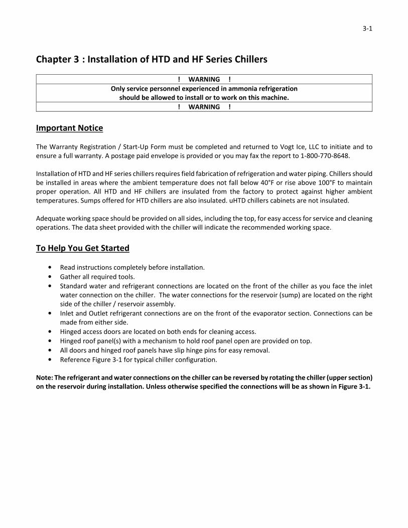
Important Notice
The Warranty Registration / Start-Up Form must be completed and returned to Vogt Ice, LLC to initiate and to
ensure a full warranty. A postage paid envelope is provided or you may fax the report to 1-800-770-8648.
Installation of HTD and HF series chillers requires field fabrication of refrigeration and water piping. Chillers should
be installed in areas where the ambient temperature does not fall below 40°F or rise above 100°F to maintain
proper operation. All HTD and HF chillers are insulated from the factory to protect against higher ambient
temperatures. Sumps offered for HTD chillers are also insulated. uHTD chillers cabinets are not insulated.
Adequate working space should be provided on all sides, including the top, for easy access for service and cleaning
operations. The data sheet provided with the chiller will indicate the recommended working space.
To Help You Get Started
• Read instructions completely before installation.
• Gather all required tools.
• Standard water and refrigerant connections are located on the front of the chiller as you face the inlet
water connection on the chiller. The water connections for the reservoir (sump) are located on the right
side of the chiller / reservoir assembly.
• Inlet and Outlet refrigerant connections are on the front of the evaporator section. Connections can be
made from either side.
• Hinged access doors are located on both ends for cleaning access.
• Hinged roof panel(s) with a mechanism to hold roof panel open are provided on top.
• All doors and hinged roof panels have slip hinge pins for easy removal.
• Reference Figure 3-1 for typical chiller configuration.
Note: The refrigerant and water connections on the chiller can be reversed by rotating the chiller (upper section)
on the reservoir during installation. Unless otherwise specified the connections will be as shown in Figure 3-1.

3-2
Figure 3-1 – Typical Chiller Orientation
Recommended Service and Cleaning Clearances
Minimum recommended clearances for service and cleaning:
• 48" on all sides
• 36" above the chiller for access to the water distribution pan(s) and header(s) for cleaning.
Access doors are provided on the front, rear, and top of the chiller.
Note: Connections can be located on the opposite side of the unit by rotating the upper chiller section 180°
before placing it on the sump.
Tools Required for Installation
To install the chiller, you will need two to three people whose skills include mechanical, welding, and plumbing
capabilities as well as a qualified electrician. The following is a list of tools required for safe erection and assembly
of the chiller:
• Wrenches and sockets (a full set up to 1 1/8")
• Phillips (not cross-point) and standard (slotted) screw drivers
• Level (four feet long)
• Tape measure (thirty feet long)
• Pry bar
• Lifting straps (2000#)
• Welder suitable for carbon-to-stainless steel
• Framing square
• Forklift or crane
3-3
Always remember –SAFETY FIRST!!!
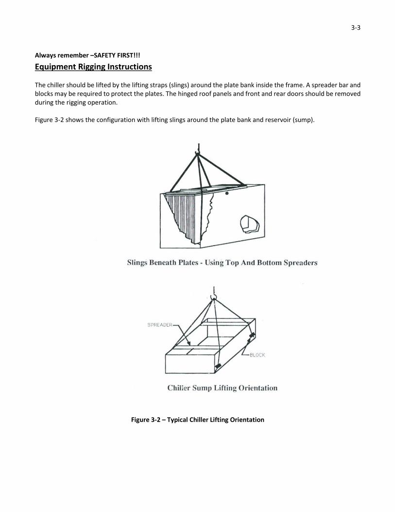
Equipment Rigging Instructions
The chiller should be lifted by the lifting straps (slings) around the plate bank inside the frame. A spreader bar and
blocks may be required to protect the plates. The hinged roof panels and front and rear doors should be removed
during the rigging operation.
Figure 3-2 shows the configuration with lifting slings around the plate bank and reservoir (sump).
Figure 3-2 – Typical Chiller Lifting Orientation

3-4
Hoisting or Moving
If a chiller is installed in a location that requires the unit to be lifted by means of a crane, Vogt requires that the
lifting and/or slinging be done from the bottom of the unit. Use a spreader at the top of the unit to prevent the
plates from being damaged. A competent rigging and hoisting contractor can handle the job without danger or
damage to the chiller.
If a chiller has to be moved along a floor, road, driveway, etc., use either pipes as rollers or dollies (of sufficient
capacity) under the unit or if available a large forklift on both ends should be used. The unit can also be moved by
a large forklift from one end with heavy duty dollies under each corner of the other end.
! CAUTION !
Never lift or sling the chiller with devices fastened to the top frame structure.
Lift the chiller only from the bottom of the plate bank.
! CAUTION !
Before hoisting, the rigger must ensure that the load is properly balanced to prevent tilting or tipping of the Chiller.
Test the load before lifting it off the truck or ground.
! WARNING !
Hoisting or moving heavy equipment should only be done by competent rigging and hoisting contractors.
Never allow personnel to go under the unit while it is in the air.
Failure to carefully follow these instructions could result in permanent injury or loss of life.
! WARNING !
The following tables list the shipping weights of all standard chillers and reservoirs. Consult the factory for shipping
weights of special or self-contained chiller that include the high side or other options.
Shipping and Operating Weights, 48” HTD Chiller Models
Model Shipping Weight
(lbs)
Operating
Weight (lbs)
Dimensions (in)
Length Width
HTDx 480601 1,482 2,466
68 36
HTDx 480602 1,587 2,637
HTDx 480603 1,692 2,809
HTDx 480604 1,797 2,981
HTDx 480605 1,902 3,153
HTDx 480606 2,001 3,324
HTDx 480607 2,112 3,496
HTDx 481207 2,540 4,634
68 60
HTDx 481208 2,645 4,805
HTDx 481209 2,750 4,977
HTDx 481210 2,855 5,149
HTDx 481211 2,960 5,320
HTDx 481212 3,065 5,492
HTDx 481213 3,170 5,664
Table 3-1 – Shipping and Operating Weights for 48” HTD Series Chillers

3-5
Shipping and Operating Weights, 72” HTD Chiller Models
Model Shipping Weight
(lbs)
Operating
Weight (lbs)
Dimensions (in)
Length Width
HTDx 721207 3,347 6,296
92 60
HTDx 721208 3,505 6,557
HTDx 721209 3,663 6,818
HTDx 721210 3,821 7,079
HTDx 721211 3,979 7,340
HTDx 721212 4,137 7,601
HTDx 721213 4,295 7,862
Table 3-2 – Shipping and Operating Weights for 72” HTD Series Chillers

3-6
Shipping and Operating Weights, 96” HTD Chiller Models
Model Shipping Weight
(lbs)
Operating
Weight (lbs)
Dimensions (in)
Length Width
HTDx 960601 2,321 4,087
116 36
HTDx 960602 2,531 4,436
HTDx 960603 2,741 4,786
HTDx 960604 2,951 5,135
HTDx 960605 3,161 5,485
HTDx 960606 3,371 5,834
HTDx 960607 3,581 6,184
HTDx 961207 4,147 7,959
116 60
HTDx 961208 4,357 8,308
HTDx 961209 4,567 8,657
HTDx 961210 4,777 9,007
HTDx 961211 4,987 9,357
HTDx 961212 5,197 9,706
HTDx 961213 5,407 10,056
HTDx 961814 6,195 12,192
116 83.5
HTDx 961815 6,405 12,542
HTDx 961816 6,615 12,981
HTDx 961817 6,825 13,241
HTDx 961818 7,035 13,590
HTDx 961819 7,245 13,939
HTDx 961820 7,455 14,289
HTDx 963020 8,055 14,623
HTDx 963021 8,265 14,959
HTDx 963022 8,475 15,296
HTDx 963023 8,685 15,632
HTDx 963024 8,895 15,968
HTDx 963025 9,105 16,304
HTDx 963026 9,315 16,640
HTDx 963027 9,525 19,679
HTDx 963028 9,735 17,313
HTDx 963029 9,945 17,649
HTDx 963030 10,155 17,985
Table 3-3 – Shipping and Operating Weights for 96” HTD Chiller Models

3-7
Shipping and Operating Weights, uChiller
Model Shipping Weight
(lbs)
Operating
Weight (lbs)
Dimensions (in)
Length Width
UHTDx 480601 1,395 2,370
68 36
UHTDx 480602 1,500 2,485
UHTDx 480603 1,620 2,610
UHTDx 480604 1,725 2,740
UHTDx 480605 1,840 2,780
UHTDx 480606 1,965 3,025
UHTDx 480607 2,085 3,026
Table 3-4 – Shipping and Operating Weights for uHTD Series Chiller Models
Shipping and Operating Weights, 144” HF Chiller Models
Model Shipping Weight
(lbs)
Operating
Weight (lbs)
Dimensions (in)
Length Width
HFx 1440601 1,935 4,355
163 36
HFx 1440602 2,065 4,495
HFx 1440603 2,195 4,635
HFx 1440604 2,340 4,840
HFx 1440605 2,485 5,045
HFx 1440606 2,625 5,250
HFx 1440607 2,765 5,450
HFx 1441207 3,325 7,700
163 60
HFx 1441208 3,460 7,895
HFx 1441209 3,585 8,080
HFx 1441210 3,715 8,275
HFx 1441211 3,885 8,510
HFx 1441212 3,995 8,680
HFx 1441213 4,105 8,920
Table 3-5 – Shipping and Operating Weights for 144” HF Series Chiller Models
3-8
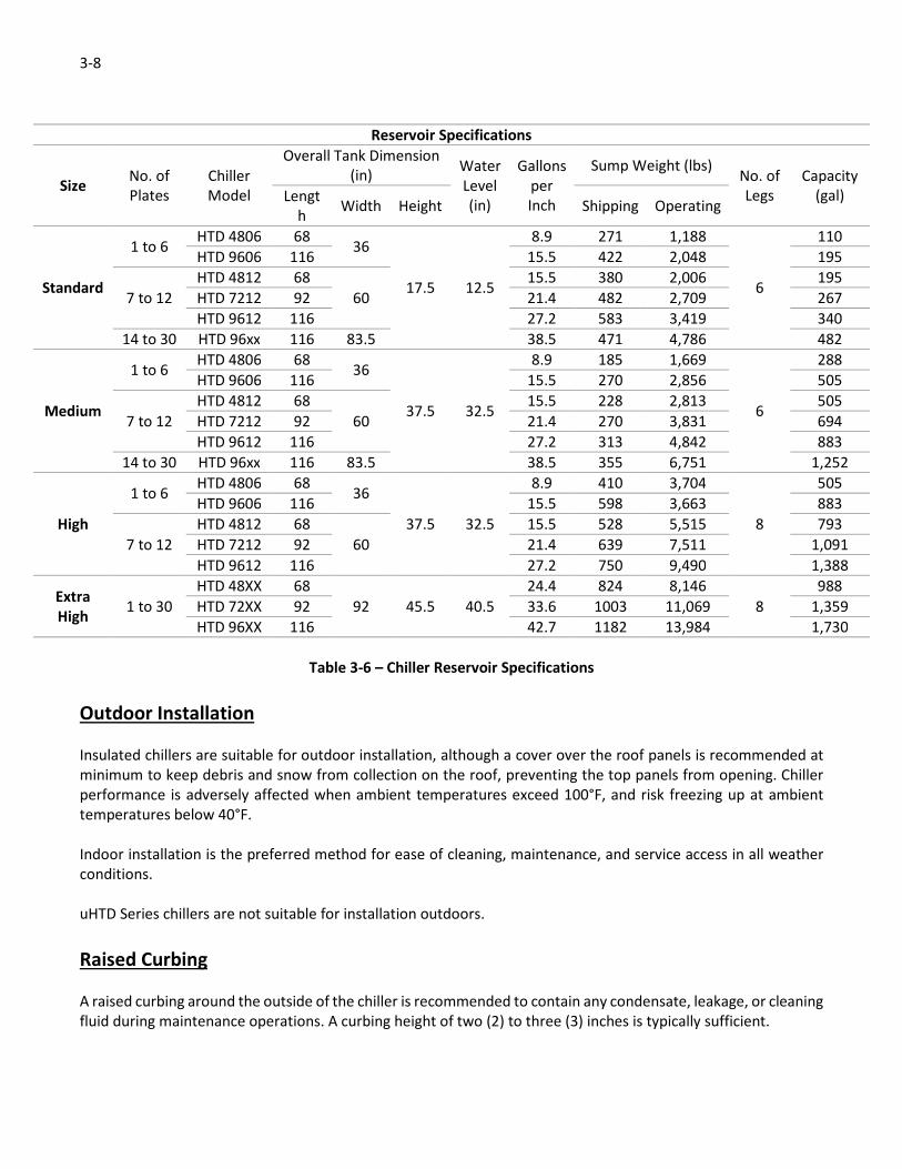
Reservoir Specifications
Size No. of
Plates
Chiller
Model
Overall Tank Dimension
(in) Water
Level
(in)
Gallons
per
Inch
Sump Weight (lbs) No. of
Legs
Capacity
(gal) Lengt
h Width Height Shipping Operating
Standard
1 to 6 HTD 4806 68
36
17.5 12.5
8.9 271 1,188
6
110
HTD 9606 116 15.5 422 2,048 195
7 to 12
HTD 4812 68
60
15.5 380 2,006 195
HTD 7212 92 21.4 482 2,709 267
HTD 9612 116 27.2 583 3,419 340
14 to 30 HTD 96xx 116 83.5 38.5 471 4,786 482
Medium
1 to 6 HTD 4806 68
36
37.5 32.5
8.9 185 1,669
6
288
HTD 9606 116 15.5 270 2,856 505
7 to 12
HTD 4812 68
60
15.5 228 2,813 505
HTD 7212 92 21.4 270 3,831 694
HTD 9612 116 27.2 313 4,842 883
14 to 30 HTD 96xx 116 83.5 38.5 355 6,751 1,252
High
1 to 6 HTD 4806 68
36
37.5 32.5
8.9 410 3,704
8
505
HTD 9606 116 15.5 598 3,663 883
7 to 12
HTD 4812 68
60
15.5 528 5,515 793
HTD 7212 92 21.4 639 7,511 1,091
HTD 9612 116 27.2 750 9,490 1,388
Extra
High 1 to 30
HTD 48XX 68
92 45.5 40.5
24.4 824 8,146
8
988
HTD 72XX 92 33.6 1003 11,069 1,359
HTD 96XX 116 42.7 1182 13,984 1,730
Table 3-6 – Chiller Reservoir Specifications
Outdoor Installation
Insulated chillers are suitable for outdoor installation, although a cover over the roof panels is recommended at
minimum to keep debris and snow from collection on the roof, preventing the top panels from opening. Chiller
performance is adversely affected when ambient temperatures exceed 100°F, and risk freezing up at ambient
temperatures below 40°F.
Indoor installation is the preferred method for ease of cleaning, maintenance, and service access in all weather
conditions.
uHTD Series chillers are not suitable for installation outdoors.
Raised Curbing
A raised curbing around the outside of the chiller is recommended to contain any condensate, leakage, or cleaning
fluid during maintenance operations. A curbing height of two (2) to three (3) inches is typically sufficient.
3-9
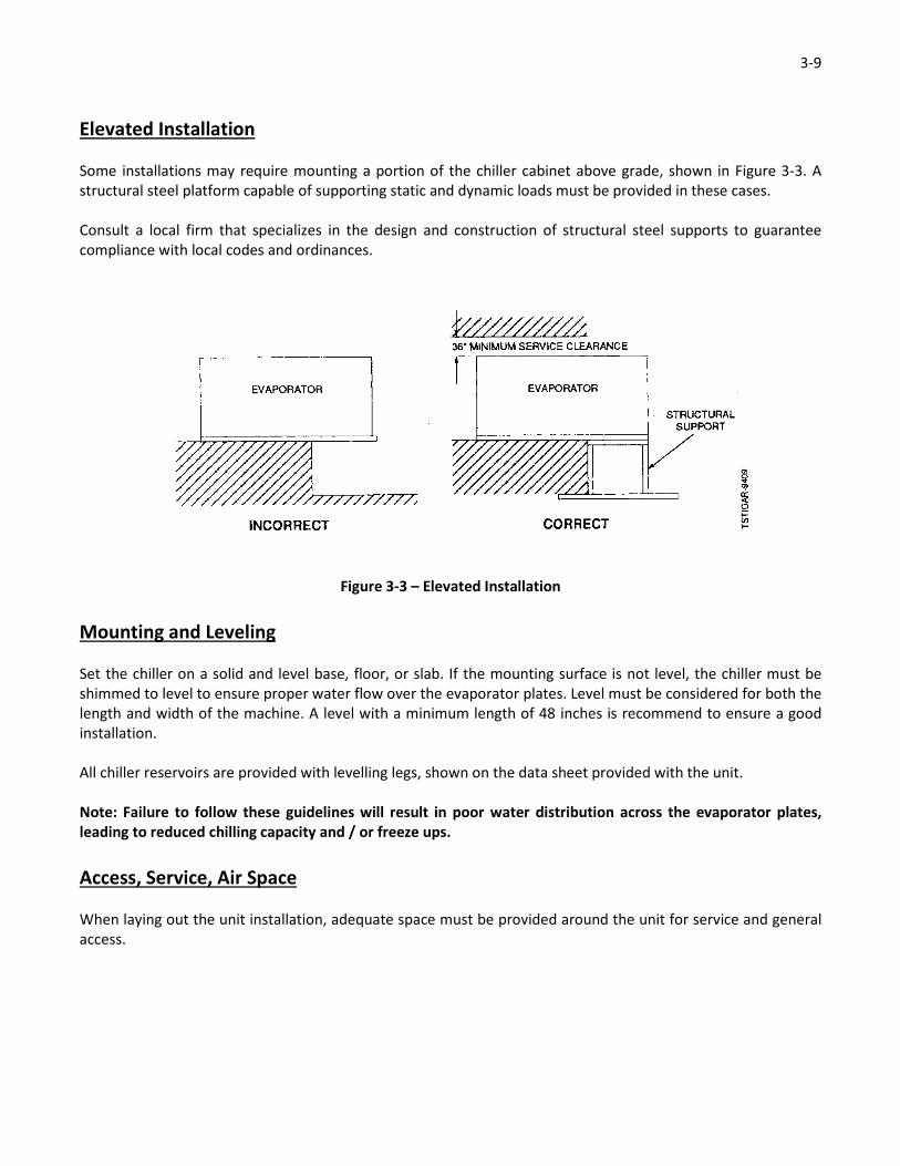
Elevated Installation
Some installations may require mounting a portion of the chiller cabinet above grade, shown in Figure 3-3. A
structural steel platform capable of supporting static and dynamic loads must be provided in these cases.
Consult a local firm that specializes in the design and construction of structural steel supports to guarantee
compliance with local codes and ordinances.
Figure 3-3 – Elevated Installation
Mounting and Leveling
Set the chiller on a solid and level base, floor, or slab. If the mounting surface is not level, the chiller must be
shimmed to level to ensure proper water flow over the evaporator plates. Level must be considered for both the
length and width of the machine. A level with a minimum length of 48 inches is recommend to ensure a good
installation.
All chiller reservoirs are provided with levelling legs, shown on the data sheet provided with the unit.
Note: Failure to follow these guidelines will result in poor water distribution across the evaporator plates,
leading to reduced chilling capacity and / or freeze ups.
Access, Service, Air Space
When laying out the unit installation, adequate space must be provided around the unit for service and general
access.

3-10
Water System
General Requirements
Water temperature and flow are used to determine the number of evaporator plates required for the application.
All capacities are based on the entering and leaving water temperatures, specific heat of the fluid, and the flow
rate over the chiller plates. This determines the heat load for the system. The number of plates used in the chiller
is determined by considering the heat load against the saturated suction temperature at which the system will be
running. When water is the fluid being chilled, the minimum evaporator temperature is 26°F to prevent ice
formations on the plates.
Each water distribution pan contains many small holes that direct flow across the surface of the evaporator plates.
In operation, these holes may become plugged with debris or scale, requiring periodic cleaning to maintain the
desired chilling capacity.
Water Supply and Drain Connections
Properly size the supply and drain piping to the chiller to deliver the specified flow and pressure on the data sheet.
The data sheet will also contain information about the size and location of each.
Water connection points on the chiller are designed for a minimum inlet pressure of 5 PSIG and a maximum of
100 PSIG. When utility water pressure exceeds 100 PSIG, a pressure reducing valve must be installed on the supply
line to the chiller cabinet. An expansion tank or other device may need to be installed in high water pressure
systems to prevent water hammer at the chiller.
Pump connections are provided at the bottom of the reservoir to be used in recirculation or distribution systems.
The reservoir also contains connection points for an overflow connection to handle surge volumes and a drain
connection to aid in cleaning operations. These connections should be piped to a drain location.
Water Quality and Treatment
When the fluid to be cooled is water, its quality can adversely affect the performance and corrosion resistance of
the system if proper corrective action is not taken. A water analysis performed by a water treatment company is
recommended.
All city water sources contain dissolved solids (minerals), gasses, and other organics. The degree of concentration
of each of these depends on location, the type of treatment at the utility source (i.e. – water treatment plant),
and the local geology.
At high enough concentrations, minerals in the water can cause scale build up on the evaporator plates. This most
frequently is in the form lime and calcium build-up, which can be treated with conventional scale cleaning agents.
Some water sources contain higher amounts of silica, which forms a clear, glass-like scale. Mechanical cleaning is
the only removal method for silica scale. If the plates are not cleaned of fouling, the leaving water temperature
cannot be obtained. Details on cleaning procedures are provided in the maintenance section.
Free chlorine is common in utility water sources. As it is discharged from the water distribution header and falls
over the evaporator plates, it is released from the water in gaseous form. High concentrations of chlorine in the
source water will lead to high concentrations of chlorine gas inside of the chiller cabinet, causing corrosion of
3-11
stainless steel surfaces that are not wetted during operation. This includes the water distribution pans, chiller
frame, exterior panel surfaces and refrigerant headers. Additionally, it can be a hazard to service technicians, who
may become nauseous or develop headaches during prolonged exposure. The standard chiller offering contains a
vent hood that is designed to allow chlorine gas to escape from the machine. If this standard offering is declined,
an alternate venting method must be installed. Chlorine can be vented during cleaning routines when the chiller
cabinet doors are opened for this operation. When this is performed weekly, the chlorine gas concentration is
often not high enough to be a cause for concern.
Due to the low water temperatures experienced in a chilling system, organic matter in the source water can lead
to mold, slime, and fungal growth in the chiller. Left unchecked, fungal and slime growth can affect the water flow
across the plates, leading to freeze ups and poor chiller performance. The application will determine the extent
to which bio-growth affects the water supply itself, but it can pose a hazard to service technicians. Consult a local
water treatment firm about any bio-growth in your chiller.
All of these can be prevented with the use of an appropriate water pre-treatment system. If minerals, gasses, and
organics are removed from the water supply before reaching the chiller, it will extend the life of the chiller and
reduce cleaning intervals by keeping the evaporator plates and water distribution system clean. Consult a local
water treatment firm about pre-treatment options for your installation.
At minimum, Vogt recommends that a strainer be installed in the make-up water line to prevent larger debris
from plugging the holes in the water distribution pan(s). Strainers are offered as an option for all chillers.
Water Temperature
The temperature of the water being fed to the chiller is critical to achieving the designed capacity of the unit.
Typical incoming water temperatures are between 35°F and 90°F. Leaving water temperatures can be within 0.5°F
of the freezing point of the fluid. For water chilling applications, the recommended minimum incoming water
temperature is 35°F to avoid freeze up conditions.
Water Distribution Header
A PVC water distribution header is located inside the unit. The laterals that branch off of the main lines can be
removed from the fittings into which they are inserted for cleaning. Plastic caps are located on the end of the
laterals to permit full access to the pipe ID from both ends.
Holes in the water header are sized for even distribution of the fluid into the pan and large enough to pass solids
in the fluid stream. Reference Water Distribution Pan Filter below for removal of solids and debris from the fluid
stream.
Stainless steel water distribution headers with sanitary fittings for easy disconnect and removal of the complete
water distribution system are available as an option.
Water Distribution Pan
A stainless steel water distribution pan is located on top of the chiller plates to allow uniform distribution of the
fluid across the plates. The size and number of holes in the pans are selected to match the flow requirements
specified by the customer. This design point considers the water pan(s) being half full. All pans are designed to
3-12
maintain proper flow over a 2:1 flow range that covers a water level from approximately 1” minimum to 4”
maximum in the pan.
Note: Water levels below 1” in the water distribution pan will result in water wicking (separation of the fluid
flow over the plates) and will result in freeze ups due to erratic fluid flow to the plates. Water levels above 4”
can result in excessive splashing and also result in freeze-ups due to the splashing freezing on the refrigerant
headers or other surfaces that are normally not wetted.
Larger chillers normally use multiple water distribution pans to make them easier to remove for cleaning.
Water Distribution Pan Filter
A filter pad is located in the bottom of the water distribution pan for all non-USDA applications to filter debris that
is large enough to plug the holes in it. For USDA applications, a perforated PVC sheet is used instead as a filter
element, which requires more frequent cleaning to ensure proper distribution at all times.
Insulation
Fluid lines connected to the chiller should be insulated by others to reduce heat infiltration and condensation.
Electrical Connections
Chillers are not provided with electrical components and do not require field wiring to the cabinet. Methods of
refrigerant and water control to the chiller cabinet are by others.
Refrigerant Connections
All piping in the chiller is provided standard as 304 stainless steel. Optional 304L piping is available. Typically,
refrigerant connections are stubbed out on the right side of the unit. These connections can be easily reversed by
rotating the chiller on the reservoir during installation.
Note: Although the connections can be reversed in the field please specify the side the refrigerant headers
should exit when the chiller is ordered to ensure the package along with any options provided can be properly
assembled in the field.
Piping in a refrigerant system has two functions:
1. To carry the refrigerant through the system as a liquid, a gas, or a liquid/gas mixture with a minimum
pressure drop.
2. To return any oil entrained in the refrigerant to the compressor.
Avoid trapping the lines except for specific purposes. If traps are used, the horizontal dimension should be as short
as possible to avoid excessive trapping of oil. Suction mains should be pitched toward the compressor.
When connecting refrigeration piping, you must follow and adhere to all piping codes required in the jurisdiction
of installation. Vogt recommends ASHRAE 15 “Safety Standard for Refrigeration Systems,” and ASME B31.5
“Refrigeration Piping and Heat Transfer Components,” which are required in many locations throughout the
world. Make sure all piping is kept clean, dry, and contaminate free. All piping should be supported properly.

3-13
If carbon steel piping is connected to the chiller, special care must be taken to shield the cabinet and evaporator
plates from carbon dust. If left unprotected, carbon dust can settle on the stainless steel surfaces, causing pitting
and corrosion.
Refrigerant piping connection sizes and locations are listed on the data sheet provided with each chiller.
Chillers are vacuum leak checked and shipped with a small nitrogen holding charge to prevent contamination
during shipping and storage. To keep the system clean, avoid making field connections that may remain open for
extended periods prior to start-up of the system.
Leak Test of Field Installed Refrigeration Piping
Testing for leaks ensure a tight system that operates without loss of refrigerant. Field piping leak tests must be
performed according to piping codes required in the jurisdiction of installation. Vogt recommends following the
guidelines in ASHRAE 15 “Safety Standard for Refrigeration Systems,” and ASME B31.5 “Refrigeration Piping and
Heat Transfer Components.” The maximum recommended test pressure for the evaporator plates is 150 PSIG.
When the appropriate test pressure has been obtained, leak checks can be performed easily with a soap solution.
This can be purchased from a local refrigeration supply store or mixed on site with four (4) parts water and one
(1) part liquid soap. A few drops of glycerin can be added to the mixture to improve capillary action.
Apply the soap solution to all weld joints and flanges with a narrow brush or spray bottle. Bubbles will form if a
leak is present. Mark any leak joints that are discovered and relieve the pressure from the system before repairing.
Weld joints should be repaired by grinding out the defective area and re-welding.
! DANGER !
Never attempt to repair weld joints while a piping system is still under pressure.
Performing welding or grinding operations under pressure can result in a sudden release of pressure and
result in serious injury or loss of life.
! DANGER !

3-14
Evacuating the System
Refrigeration systems operate best when only refrigerant is present in them. Steps must be taken to remove all
air, water vapor, and other non-condensables from the chiller unit before charging it with refrigerant. If these are
left in the system, various operating difficulties will be encountered. Water will decrease the capacity of the
evaporator and cause formation of ice in orifice openings causing restriction or complete shut-off of refrigerant
flow. Air and non-condensables will lodge in the condenser, causing a rise in system head pressure that will result
in decreased capacity at the chiller.
A properly evacuated system is dry and free of air, water, and non-condensable gasses. Evacuation operations
should be performed when the ambient temperature is in excess of 60°F to allow for proper moisture boil off.
Use a high vacuum pump and a gauge rated for vacuum service. The pump used should be capable of obtaining a
blanked-off pressure of 10 microns or less. Connect it the system and allow it to operate until the system pressure
is below 500 microns as indicated by the vacuum gauge.
If the chiller is installed in a system containing a large volume of new piping, the system may need to be evacuated
multiple times. This can be done with the following method:
1. Seal off the system and allow the vacuum pump to reduce the pressure as low as possible.
2. Continue to operate the pump for five (5) or six (6) hours.
3. Shut off the pump and let the system stand for five (5) or six (6) hours.
4. Break the vacuum and increase the system pressure with oil free dry nitrogen to zero (0) PSIG.
5. Seal off the system and allow the pump to reduce the pressure below 500 microns.
6. Continue to operate the pump for two (2) or three (3) hours.
7. Shut off the pump and let the system stand for no less than three (3) hours.
8. Break the vacuum and increase the system pressure with oil free dry nitrogen to zero (0) PSIG.
9. Seal the system for a third time and allow the pump to reduce the system pressure below 500 microns.
10. Continue to operate the pump for six (6) hours.
11. Shut off the pump and let the system stand for 12 hours.
12. Break the vacuum and increase system pressure with oil free dry nitrogen to just above zero (0) PSIG.
13. Evacuate the system to below 500 microns and charge with refrigerant.

3-15
Charging the System with Refrigerant
! CAUTION !
Only service personnel experienced in ammonia refrigeration and qualified to work on such equipment
should be allowed to charge the system with refrigerant.
It is very important that you are familiar with and adhere to all local, state, and federal regulations and
ordinances regarding the handling, storage, and use of anhydrous ammonia.
An approved ammonia mask should be readily available for use in an emergency and all personnel should
be aware of its location and proper use.
! CAUTION !
All chiller models are furnished without a refrigerant charge. The unit must be evacuated and then charged with
the appropriate refrigerant for the application.
Whenever refrigerant is added to any chiller system, extreme care should be taken during the charging process.
Avoid overcharging the system as it will create high discharge pressures.
Table 3-7 lists the operating charge for each individual evaporator plate. To determine the operating charge of
your chiller, simply multiply the number of plates in the chiller by the weight shown in the table.
Operating Charge Weights for Individual Evaporator Plates with Various Refrigerants
Evaporator Feed
Type Plate Size
Charge Weight (lbs)
R-717 R-404A R-22 20% Propylene
Glycol
Liquid
Recirculating
48” 7 12 13 20
60” 10 18 20 30
72” 14 25 27 41
144” 8 13 15 22
Flooded
48” 11 19 21 -
60” 16 29 32 -
72” 22 39 43 -
144” 12 21 24 -
Direct Expansion
48” 6 11 12 -
60” 9 16 18 -
72” 13 22 25 -
144” 7 12 13 -
Table 3-7 – Evaporator Plate Operating Charges
3-16
Relief Devices
Relief valves must be installed on all pressure vessels to prevent excessive pressure build-up in the system. They
must be vented to a safe discharge point. Consult local, state, and federal regulations, codes, and ordinances
regarding the safe discharge of refrigerants, particularly ammonia. Industrial Codes such as ASHARE 15 and ASME
B31.5 provide guidelines for the safe design and installation of pressure relief valve discharge piping.
Vogt provides pressure relief valves on vessels purchased as options with your chiller. These valves are sized
according to the guidelines in ASHRAE 15, with consideration given to the size of the vessel.
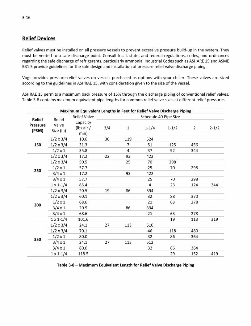
ASHRAE 15 permits a maximum back pressure of 15% through the discharge piping of conventional relief valves.
Table 3-8 contains maximum equivalent pipe lengths for common relief valve sizes at different relief pressures.
Maximum Equivalent Lengths in Feet for Relief Valve Discharge Piping
Relief
Pressure
(PSIG)
Relief
Valve
Size (in)
Relief Valve
Capacity
(lbs air /
min)
Schedule 40 Pipe Size
3/4 1 1-1/4 1-1/2 2 2-1/2
150
1/2 x 3/4 10.6 30 119 524
1/2 x 3/4 31.3 7 51 125 456
1/2 x 1 35.8 4 37 92 344
250
1/2 x 3/4 17.2 22 93 422
1/2 x 3/4 50.5 25 70 298
1/2 x 1 57.7 25 70 298
3/4 x 1 17.2 93 422
3/4 x 1 57.7 25 70 298
1 x 1-1/4 85.4 4 23 124 344
300
1/2 x 3/4 20.5 19 86 394
1/2 x 3/4 60.1 32 88 370
1/2 x 1 68.6 21 63 278
3/4 x 1 20.5 86 394
3/4 x 1 68.6 21 63 278
1 x 1-1/4 101.6 19 113 319
350
1/2 x 3/4 24.1 27 113 510
1/2 x 3/4 70.1 46 118 480
1/2 x 1 80.0 32 86 364
3/4 x 1 24.1 27 113 512
3/4 x 1 80.0 32 86 364
1 x 1-1/4 118.5 29 152 419
Table 3-8 – Maximum Equivalent Length for Relief Valve Discharge Piping
3-17
Post Installation Clean Up
Three critical steps are required to ensure the chiller operates reliably and is corrosion free for the life of the
installation. The three Golden Rules are:
1. Ship it clean
2. Install it clean
3. Keep it clean
Rule #1. Ship it Clean
Vogt passivates all chillers prior to shipment in a nitric acid solution to ensure that contaminates from the
manufacturing process are completely removed from the stainless steel surfaces. This process also provides a
protective barrier against corrosion. After passivation, the exterior panels are installed, and all areas of the chiller
are cleaned.
Prior to shipment, the chiller and reservoir (if supplied) are stretch wrapped for protection during transportation
to the job site.
Rule #2. Install it Clean
Installation of the chiller requires connection of carbon steel piping to connections on the chiller as well as other
normal grinding, and welding processes that can contaminate the stainless surfaces of the chiller. Every effort
must be made to eliminate the possibility of this contamination including covering the chiller to avoid exposure
of the surfaces during installation. Upon completion of the installation process, clean all surfaces using a citric acid
cleaner followed by a fresh water rinse.
Rule #3. Keep it Clean
After the chiller is put into service, it must be cleaned on a regular basis to ensure that the stainless steel surfaces
maintain their passive layer. Cleaning and sanitizing procedures may vary depending on the application and plant
guidelines.
Vogt recommends that the chiller should be opened on a weekly basis and the entire interior and exterior surfaces
flushed with fresh water at a minimum. Areas such as the frame and sides of the water distribution pan should be
watched closely. These areas typically have stagnant water droplets that draw free chlorine. If left long enough,
the concentration will increase to the point that the passive layer is stripped, resulting in pitting of the stainless
steel.
The key to a long corrosion free life for your investment is to keep it clean.
Chiller Protection during Installation
Once set and leveled, a tarp or canvas cover should be used to cover the chiller during all piping and installation.
The cover will protect the stainless surfaces from carbon contamination. Reinstall exterior panels after mounting
the chiller to protect the reservoir (if supplied) and the interior of the cabinet.

3-18
Weld Zone Clean Up
Installation of the chiller includes welding the refrigerant connections. After the welding has been completed, it
is recommended that these areas cleaned. Use a wire brush to remove loose scale and passivate the stainless
steel section of all carbon-to-stainless weld joints. Follow the instructions on the passivating agent or contact Vogt
for additional information. After passivating, the weld area should be rinsed with fresh water.
! CAUTION !
Passivation processes must be performed according to the instructions provided by the product
manufacture.
Only specially trained personnel should perform this type of treatment.
! CAUTION !
When using the passivating gel, proper safety equipment, including eye protection and gloves must be used.
Follow all instructions on the product for proper use and safety precautions.
Other Areas
In addition to weld zones, any area that has been in contact with carbon steel (tools, pry bars, moving devices,
etc.) should be examined for signs of discoloration or contamination. If necessary, passivate these areas.
The lifting process can introduce carbon contaminants to the chiller plates, particularly the ones at each end where
the straps were in the most contact. It may be necessary to passivate these areas prior to operation.
Final Cleaning
Clean the entire chiller once the installation process has been completed. Using a citric acid cleaning agent in a
spray bottle, wet all of the stainless steel surfaces starting on the inside of the chiller. If necessary, use a Scotch-
BriteTM Light Duty Cleaning Pad No. 66 (white in color), or equivalent, to clean difficult areas. These pads are
designed specifically for cleaning stainless steel.
Avoid using abrasive pads on the stainless steel surfaces as they can strip off the passive layer, leading to pitting.
After application of the citric acid cleaning agent, rinse with fresh, low chlorine content water.
Note: Citric acid cleaning agents are environmental friendly and can be safely disposed in local drain
connections.
After the interior surfaces are cleaned and rinsed, the same procedure should be followed to clean the exterior
surfaces.
If the chiller is to be put into service, no additional action is required. If the chiller will not be put into immediate
service, it is recommended that it be covered until the time it is activated.
Reference the Refrigerant Connections section for additional requirements for securing idle or inactive systems.

3-19
Installation Review : A Checklist
� Chiller securely mounted to reservoir (if supplied)
� Chiller (or reservoir) securely mounted to floor or suitable structural base frame
� All accessory components (oil pots, surge drums, valve packages, etc.) are properly installed
� Field piping connections are per the supplied data sheet
� Field piping weld joints cleaned, passivated (as needed) and leak free
� Evaporator plates and associated piping properly evacuated and charged with refrigerant
� Water supply and drain piping installed and leak free
� Relief devices properly installed and vented to safe location

3-20
4-1
Chapter 4 : Operation
General Information
HTD and HF series chillers consist of a bank of stainless steel plates mounted in a stainless steel frame. The cabinet
is enclosed by two (2) inch insulated panels and doors on the sides and top. The bottom of the unit is open and
sits on top of an insulated sump. Chillers can also be provided without a sump for mounting over raceways or
existing water collection systems. Stainless steel refrigerant inlet and outlet headers are provided on the same
side as the water inlet connection.
Additional vessels and valve kits for liquid feed and suction lines may have been purchased as optional equipment.
A stainless steel water distribution pan and a PVC distribution header are installed on top of the plates to evenly
distribute flow across the plates and the plate bank. Water depth in the pan should be no less than one (1) inch
and no more than four (4) inches to maintain good system operation. Running too little or too much water in the
pan can result in a freeze-up condition.
An overflow connection is provided on all reservoirs to allow for surge volumes in the event of a system
interruption or significant changes in the incoming water supply. During a shutdown, water that drains down into
the sump from the distribution pan(s) above may cause an overflow condition. Field piping must be supplied from
this connection point to a drain line.
Liquid recirculating, flooded, and direct expansion chillers can be turned off without pumping down the unit during
daily operation. If the system is to be shut down for more than 48 hours, a pump down of the evaporator section
is recommended.
4-2
Flooded System
Principle of Operation
Liquid refrigerant is gravity fed from a surge drum into the liquid line(s) at the bottom of the chiller cabinet. This
causes the evaporator plates to be filled internally from the bottom to top. Water is fed into the water make-up
header(s) at the top of the cabinet. The water floods the distribution pan and cascades over the outside surface
of the evaporator plates. With the central refrigeration plant running and relatively warm water falling across the
evaporator plates, the liquid refrigerant boils into a saturated vapor at the top suction headers, where it is drawn
back into the surge drum, to be carried to the central system compressor. As the water falls across the plates, it
is cooled by the boiling refrigerant. The degree of heat removal from the water is dependent upon the evaporator
suction temperature, make-up water temperature, and make-up water flow rate.
Water should be flowing over the plates prior to starting up the refrigeration system. If the refrigeration system
is started first, a layer of ice could begin to form on the plates, which may temporarily reduce chilling capacity or
cause freeze-up issues.
Surge Drum
For flooded operation, refrigerant feed to the chiller is dependent upon the use of a surge drum. The drum is
installed at an elevation higher than the top of the chiller cabinet and is based on a gravity feed principle.
Refrigerant supply to the surge drum must come from the central system High Pressure Liquid Line. This liquid is
fed into the surge drum through a valve group, filling it until the level has been satisfied by a level probe or a float
switch. The wet suction gas returning back to the surge drum from the chiller is separated in the drum and exits
via the dry suction line, passing through a suction valve regulator, and on to the central system compressor.
Oil Accumulator Drum (Oil Pot)
To prevent oil from accumulating in the evaporator of an ammonia system, an oil accumulator drum is needed in
the bottom of the liquid leg coming out of the surge drum. The oil pot must be installed at an elevation lower than
the bottom of the evaporator in order for the oil to drain properly from the system to prevent loss of chilling
capacity.

4-3
Liquid Recirculated System
Principle of Operation
Liquid refrigerant is pumped from a recirculator into the liquid line(s) at the top of the chiller cabinet. As the liquid
enters the inlet tubes at the top of the evaporator plates, it hits an orifice within the tubes and begins circulating
within the plate. Water is fed into the water make-up header(s) at the top of the cabinet. The water floods the
distribution pan and cascades over the outside surface of the evaporator plates. With the liquid recirculator
running and relatively warm water falling across the evaporator plates, the liquid refrigerant boils into a two-
phase liquid/vapor mixture at the top suction headers, where it is drawn back into the main recirculator vessel. In
the vessel, the two-phase mixture is separated, with the vapor being carried to the central system compressor. As
the water falls across the plates, it is cooled by the boiling refrigerant. The degree of heat removal from the water
is dependent upon the evaporator suction temperature, make-up water temperature, and make-up water flow
rate.
Liquid Recirculator
For liquid recirculation operation, refrigerant feed is dependent upon the use of a liquid recirculator system. A
typical recirculator consists of a primary pressure vessel with wet and dry suction connections, liquid feed
connections, refrigerant level controls, a refrigerant pump, a hand expansion valve to control the liquid flow rate
going to the chiller cabinet, and a hand expansion valve to control the make-up liquid flow rate coming from the
central system high side to the recirculator. The primary pressure vessel acts as a liquid/vapor separator for the
suction coming back from the evaporator. Wet suction leaves the chiller cabinet and enters the liquid recirculator,
where the liquid droplets fall out of the flow, sending dry vapor to the central system compressor.
Oil Accumulator Drum (Oil Pot)
To prevent oil from accumulating in the evaporator of an ammonia system, an oil accumulator drum is needed in
the bottom of the liquid leg coming out of the surge drum. The oil pot must be installed at an elevation lower than
the bottom of the evaporator in order for the oil to drain properly from the system to prevent loss of chilling
capacity.

4-4
Direct Expansion (DX) System
Principle of Operation
Liquid refrigerant is fed to a thermal expansion valve (TXV) at the bottom of the chiller cabinet from the high
pressure liquid line. As the liquid refrigerant passes through the valve, it expands into a two-phase liquid/vapor
mixture, passes through the refrigerant distributor, and partially fills the evaporator plates. Water is fed into the
water make-up header(s) at the top of the cabinet. The water floods the distribution pan and cascades over the
outside surface of the evaporator plates. With the central refrigeration plant running and relatively warm water
falling across the evaporator plates, the liquid/vapor mixture boils into a superheated vapor at the top suction
headers, where it is drawn back into the suction line of the central system compressor. The central system
compressor is protected by a suction accumulator (typically with a boil out coil) to remove any residual liquid
refrigerant resulting in a momentary overfeed of the TXV or an improper TXV setting. As the water falls across the
plates, it is cooled by the boiling refrigerant. The degree of heat removal from the water is dependent upon the
evaporator suction temperature, make-up water temperature, and make-up water flow rate.
Water should be flowing over the plates prior to starting up the refrigeration system. If the refrigeration system
is started first, a layer of ice could begin to form on the plates, which may temporarily reduce chilling capacity or
cause freeze-up issues.
TXV and Refrigerant Distributors
Critical to the proper operation of a DX chiller is the TXV and the refrigerant distributor and distribution tubes.
The TXV must be properly adjusted to a superheat setting that is favorable to the operation of the refrigeration
plant. The TXV is installed in the liquid feed line at the bottom of the chiller cabinet and the sensing bulb is installed
on the suction header at the top of the machine.
The refrigerant distributor splits the flow coming out of the TXV to each individual plate within the chiller. The
coiled tubes coming out of the distributor must be free of kinks and other deformations in order to ensure proper
operation of the chiller. Routine inspection of the distribution tubes is recommended, especially following
installation and service operations.
4-5
Glycol System
Principle of Operation
Glycol (typically ethylene or propylene glycol) is pumped directly through the top of the evaporator plates in the
chiller cabinet. The glycol acts as a secondary refrigeration circuit, the glycol itself being cooled by the primary
refrigerant, typically ammonia. Water is fed into the water make-up header(s) at the top of the cabinet. The water
floods the distribution pan and cascades over the outside surface of the evaporator plates. As the water falls
across the plates, it is cooled by the recirculated glycol. The degree of heat removal from the water is dependent
upon the glycol temperature, make-up water temperature, and make-up water flow rate.
Water should be flowing over the plates prior to starting up the refrigeration system. If the refrigeration system
is started first, a layer of ice could begin to form on the plates, which may temporarily reduce chilling capacity or
cause freeze-up issues.
Glycol Chiller Shutdown
Glycol chillers should be drained and cleaned internally and externally if they are being stored or taken out of
service for a period in excess of 30 days. Additional information is available in the maintenance section of this
manual.
Glycol Temperature
The temperature of the pumped glycol through the evaporator plates is determined by the application to obtain
the desired temperature of the fluid being chilled on the external surfaces of the plates. If the external flow is
water, then the glycol temperature should not be lower than 25°F to avoid freeze up problems. The flow rate of
glycol through the plates, along with glycol concentration and temperature, can be adjusted to achieve the desired
leaving temperature of the external fluid.
Glycol Flow
The flow rate for the glycol system is calculated for the specific application to provide maximum performance with
minimum pressure drop through the plates. Flow rates are typically selected for a pressure drop of 10 PSIG or less
(16 PSIG maximum). The number of plates used in the chiller can be adjusted to endure the flow rates meet the
pressure drop criteria.
Glycol Pressure
Glycol pumps should be sized for a pressure drop not exceeding 16 PSIG, with a drop of 10 PSIG or less being ideal.
Other piping losses must be considered as well for a properly designed system.
The maximum glycol pressure at the inlet to the chiller cabinet must not exceed 85 PSIG. Above this pressure, the
plates deflect enough to cause water distribution problems resulting in erratic flow that can reduce the chilling
capacity of the machine and cause freeze up conditions. Consult the factory if inlet pressure higher than 85 PSIG
are to be provided to the chiller.


5-1
Chapter 5 : Troubleshooting
This section lists common problems and suggests solutions with various chillers and chiller systems. Some of the
problems and solutions apply to optional equipment supplied by others and may vary. Many problems are easy
to solve if you know what caused them. If your problem is not covered in this section, call the factory direct at
502-635-3000 or 1-800-853-8648.
The following describes problems you might encounter, and provides diagnostic instructions and solutions.
Problem Causes Solution
Chiller evaporator temperature
too high;
Leaving water temperature too
high (con’t)
Discharge pressure too high –
Defective water regulating valve
(water cooled).
Check pressure sensing connection
to regulator. Replace if necessary.
Discharge pressure too high –
Fouling at condenser (water
cooled).
Clean condenser by brushing
and/or acid treatment. Consult
manufacturer for water treatment
recommendations.
Discharge pressure too high –
Faulty water pump (water or
evaporative cooled).
Replace pump. Check pump
suction and discharge for
obstructions.
Discharge pressure too high –
Fouling at condenser (air cooled).
Clean with air, water hose, or
brushing. Remove debris from
condenser inlet.
Discharge pressure too high –
Flood back valves out of
adjustment (air or evaporative
cooled).
Adjust to maintain 180 PSIG.
Discharge pressure too high – Belt
worn or loose causing belts to slip
(air or evaporative cooled).
Adjust, replace belts.
Discharge pressure too high – Fan
turning too slow (air cooled)
Change sheave to increase speed
up to FLA of motor. Consult factory
before restarting. Check for
restrictions.
NH3 pump off or flow restricted
(recirculated system).
Check pump overload. Check pump
suction and discharge for
obstructions. Check bypass
pressure regulator. Rebuild pump.
Low on NH3.
Search for leak and repair. Add
refrigerant to maintain proper level
in recirculator or surge drum
(flooded) and high pressure
receiver.
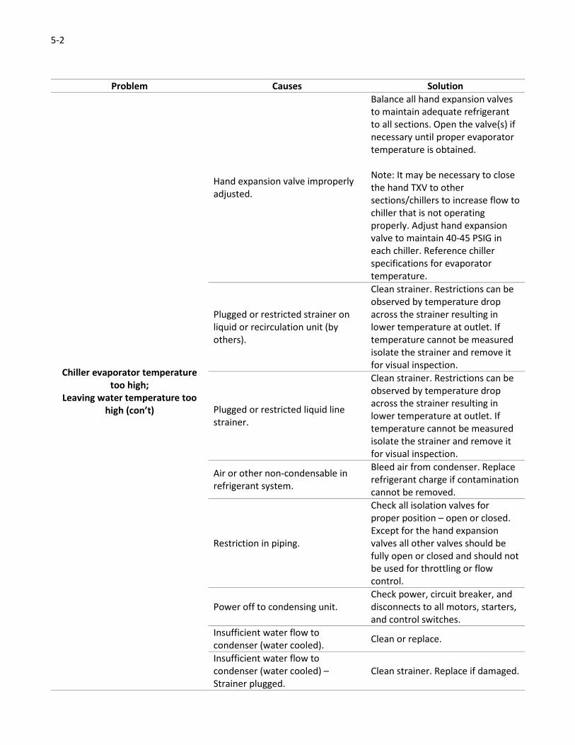
5-2
Problem Causes Solution
Chiller evaporator temperature
too high;
Leaving water temperature too
high (con’t)
Hand expansion valve improperly
adjusted.
Balance all hand expansion valves
to maintain adequate refrigerant
to all sections. Open the valve(s) if
necessary until proper evaporator
temperature is obtained.
Note: It may be necessary to close
the hand TXV to other
sections/chillers to increase flow to
chiller that is not operating
properly. Adjust hand expansion
valve to maintain 40-45 PSIG in
each chiller. Reference chiller
specifications for evaporator
temperature.
Plugged or restricted strainer on
liquid or recirculation unit (by
others).
Clean strainer. Restrictions can be
observed by temperature drop
across the strainer resulting in
lower temperature at outlet. If
temperature cannot be measured
isolate the strainer and remove it
for visual inspection.
Plugged or restricted liquid line
strainer.
Clean strainer. Restrictions can be
observed by temperature drop
across the strainer resulting in
lower temperature at outlet. If
temperature cannot be measured
isolate the strainer and remove it
for visual inspection.
Air or other non-condensable in
refrigerant system.
Bleed air from condenser. Replace
refrigerant charge if contamination
cannot be removed.
Restriction in piping.
Check all isolation valves for
proper position – open or closed.
Except for the hand expansion
valves all other valves should be
fully open or closed and should not
be used for throttling or flow
control.
Power off to condensing unit.
Check power, circuit breaker, and
disconnects to all motors, starters,
and control switches.
Insufficient water flow to
condenser (water cooled). Clean or replace.
Insufficient water flow to
condenser (water cooled) –
Strainer plugged.
Clean strainer. Replace if damaged.
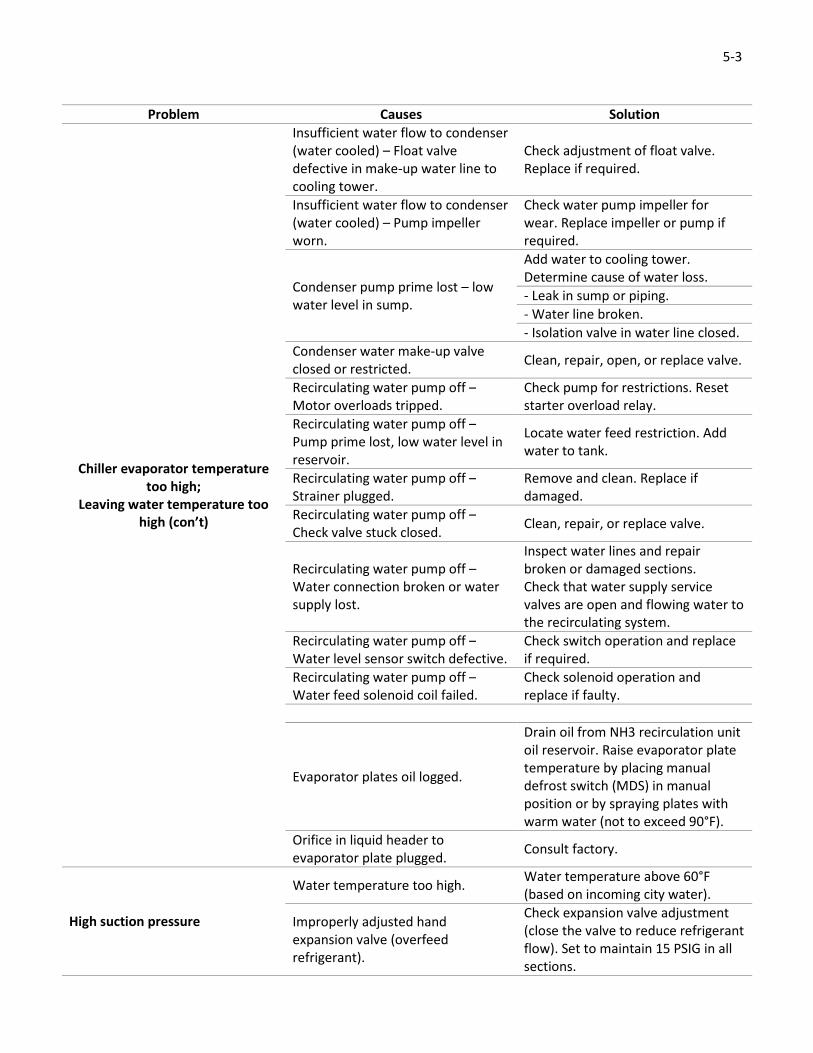
5-3
Problem Causes Solution
Chiller evaporator temperature
too high;
Leaving water temperature too
high (con’t)
Insufficient water flow to condenser
(water cooled) – Float valve
defective in make-up water line to
cooling tower.
Check adjustment of float valve.
Replace if required.
Insufficient water flow to condenser
(water cooled) – Pump impeller
worn.
Check water pump impeller for
wear. Replace impeller or pump if
required.
Condenser pump prime lost – low
water level in sump.
Add water to cooling tower.
Determine cause of water loss.
- Leak in sump or piping.
- Water line broken.
- Isolation valve in water line closed.
Condenser water make-up valve
closed or restricted. Clean, repair, open, or replace valve.
Recirculating water pump off –
Motor overloads tripped.
Check pump for restrictions. Reset
starter overload relay.
Recirculating water pump off –
Pump prime lost, low water level in
reservoir.
Locate water feed restriction. Add
water to tank.
Recirculating water pump off –
Strainer plugged.
Remove and clean. Replace if
damaged.
Recirculating water pump off –
Check valve stuck closed. Clean, repair, or replace valve.
Recirculating water pump off –
Water connection broken or water
supply lost.
Inspect water lines and repair
broken or damaged sections.
Check that water supply service
valves are open and flowing water to
the recirculating system.
Recirculating water pump off –
Water level sensor switch defective.
Check switch operation and replace
if required.
Recirculating water pump off –
Water feed solenoid coil failed.
Check solenoid operation and
replace if faulty.
Evaporator plates oil logged.
Drain oil from NH3 recirculation unit
oil reservoir. Raise evaporator plate
temperature by placing manual
defrost switch (MDS) in manual
position or by spraying plates with
warm water (not to exceed 90°F).
Orifice in liquid header to
evaporator plate plugged. Consult factory.
High suction pressure
Water temperature too high. Water temperature above 60°F
(based on incoming city water).
Improperly adjusted hand
expansion valve (overfeed
refrigerant).
Check expansion valve adjustment
(close the valve to reduce refrigerant
flow). Set to maintain 15 PSIG in all
sections.

5-4
6-1
Chapter 6 : Maintenance
To help you get the best performance from your Chiller system, follow the maintenance instructions listed below.
If you have questions concerning the maintenance or upkeep of your equipment, please contact the factory:
Vogt Ice, LLC
1000 West Ormsby Ave
Suite 19
Louisville, KY, 40210
Phone: 502-635-3235
Toll Free: 1-800-853-8648
Fax: 502-635-3024
Web: www.vogtice.com
Daily Inspections
Inspect the chiller daily to determine that the unit is operating properly. Observe the fluid flow over the plates to
ensure the water distribution system is free of debris. Check as required.
When starting, observe that the discharge and suction pressures are correct on the gauges and are stable to
ensure the proper refrigerant feed to the chiller.
Weekly Inspections
The high side of any refrigeration system should be checked on a weekly basis. Consult the supplier of your high
side regarding any specific inspections, but consider the following as a guideline:
• Check oil level in compressor
• Review the high side for signs of oil leaks
• Check the liquid level in the receiver to ensure that the level is correct and has not changed
• Inspect valve packings and relief valves for indications of refrigerant loss
The chiller unit should be visually inspected once a week. When performing a visual inspection, look for the
following:
• Refrigerant leaks
• Water leaks
• Debris in the water distribution pan filter
• Biogrowth (slime, fungus, mold, etc.)
• Even distribution of water across each individual plate
• Even distribution of water across the plate bank
• Pipe vibrations
• Rubbing of capillary tubes on DX machines
• Unusual noises
• Loose bolts, nuts, or screws

6-2
Clean the chiller weekly according to the following guidelines:
• Clean the water distribution pan, header, and filter element. The distribution header can be easily
disassembled to remove debris inside the piping, or to clear plugged holes.
• If necessary, remove the water header from the distribution pan and wipe out all loose debris in the pan.
Unplug holes as required to ensure complete flow across the plate.
• Check for indications of discoloration on the frame, pans, panels, header, and water flow. If necessary,
use citric acid to clean the areas using a non-abrasive cleaning pad. After cleaning, rinse with fresh water.
A preventive maintenance form is provided at the end of this section for use at your facility.
After First Ten and Fifty Hours of Operation
Check for indications of discoloration on the frame, pans, panels, header, and water flow. If necessary, use citric
acid to clean the areas using a non-abrasive cleaning pad. After cleaning, rinse with fresh water.
Water Scale Build-Up
One of the main concerns with any system using water is scale build-up. The three areas below are the most
commonly affected areas of the chiller:
• Evaporator plates
• Water distribution pan and headers
• Water cooled condensers (by others)
To avoid these problems, speak with a local water treatment consultant, and follow the guidelines below.
Goldenrod water treatment systems are also available from Vogt. The Goldenrod can eliminate scaling problems
in most cases. Consult the factory for additional information.
Scale Formation on Evaporator Plates
Flush plates with an acceptable ice machine cleaner – typically citric or phosphoric acid. If an unusually high
amount of scale is forming on the plates, have the water analyzed to determine the TDS count. Scale is most
commonly caused by calcium and lime in the water supply.
In some instances, silica scale may form on the evaporator plates. This type of scale requires a more aggressive
treatment than ice machine cleaners. Typically, mechanical removal (i.e. – scrubbing or scraping the plates) is
required to clear off silica scale.
Scale and Solids in Chiller Sump
Drain and flush the chiller sump at least once a week. Solids from the sump will carry into the water recirculation
system and plug the holes in the water distribution pans. The pan can be cleaned by using an air hose, a vacuum
cleaner, or a brush. If excessive or frequent cleaning is required, consult the factory.

6-3
Scaling of Condensers and Cooling Towers
Dirty or scaled tubes in water cooled condensers can cause high discharge pressure. Periodically remove the
condenser head and use a condenser tube cleaning brush to remove scale. Acids or chemical additives can also be
used. Care should be exercised when using acid. Follow directions on the container (consult local chemical
treatment supplier).
Cooling towers should be treated for scale and algae when needed.
Air cooled condensers can be washed out using a water hose and flushing out against the airflow. Prior to
performing this service, ensure that the electric circuit is disconnected and locked out. Lubricate the fan bearing
and tighten belts where equipped according to the manufacturer’s specification.
Stainless Steel Surface Cleaning
Scale on the chiller plates resulting from mineral deposits in the water and other sources of contamination can
reduce the efficiency of the plate. If left untreated, it may result in deterioration of the metal surface thus reducing
the life of the plates.
The life and efficiency of the plates are dependent on proper care and cleaning of the surface. Since conditions
and installation of equipment vary from location to location, it is difficult to provide a simple solution to selecting
a cleaning and sanitizing method. To obtain the best care for your unit, contact a local reputable supplier of
chemical and cleaning sanitizing products. Based on the knowledge of the local water conditions, the material to
be cleaned (304 and / or 304L stainless steel), and the operating conditions of the equipment, they can
recommend a cleaning and sanitizing product to meet your specific needs.
Helpful Hints
1. Chlorine will attack stainless steel. Most water supplies contain chlorine in levels too low to cause concern.
Some cleaning agents contain high levels of chlorine and should be avoided unless the cleaning process
can be closely controlled and a thorough rinsing of the plates and any other parts coming in contact with
the cleaning agent can be ensured every time.
2. Water scale can be removed using dilute nitric acid under 1% or phosphoric acid under 5% at temperatures
no higher than 105°F. These solutions must be free of salt and thoroughly flushed from all surfaces
immediately after use with a 1/4% caustic and plain water flush. Citric acid cleaning agents are also
recommended.
3. A regular de-scaling schedule eliminates the need to use stronger acids such as the nitric acid mixture to
remove scale build up. Hydrochloric and sulphuric acid should not be used.

6-4
Preventive Maintenance Form
This form can be removed and duplicated for record keeping.
Date: Model No.: Serial No.:
The following service was performed and checked:
Shift Service
1st 2nd 3rd
� � � Evaporator plates clean
� � � Frame, panel interior, water distribution pan, and headers clean
� � � Water flow across all plates providing complete wetting of plate surface
� � � Suction pressure at suction header on chiller within normal range (reference data sheet for
design point)
� � � Entering water temperature within normal limits
� � � Leaving water temperature within normal limits
� � � Inlet water pressure within normal limits
� � � Ambient temperature ______________ °F
� � � High side head pressure within normal range
� � � Compressor net oil pressure (gage reading less suction) ______________ PSIG
� � � Drained oil from oil pot
Comments:
First Shift Operator:
Second Shift Operator:
Third Shift Operator:
7-1
Chapter 7 : Optional Accessories
All chillers are offered with several optional accessories, detailed below. Each of these are required for the chiller
to function, but may already be installed at your location.
Option 1 : Water Level and Flow Control Package
The water level control package includes an electronic float switch, water solenoid valve, and water strainer. Each
component is rated for 125 PSIG inlet water pressure, and the operating pressure drop is less than 15 PSIG. The
solenoid valve fails open. Figure 2 shows this kit as installed on the chiller cabinet.
The float switch assembly consists of a SPDT switch mounted in a "splash" enclosure on the
end of a stainless steel rod. This rod acts as the adjusting arm and wiring conduit for the float
switch. A wiring junction box is mounted on top of the rod.
A set of plastic blocks are attached to the fixed lower panel in the upper frame of the chiller. The top block can be
removed and the rod assembly installed between the two blocks. Loosen the two (2) bolts holding the plastic
blocks together and move the assembly up or down as required to obtain the desired water level in the sump.
The float switch contacts are rated for pilot duty only. A solid state switching relay (LPR) is used with the float
switch to activate the motor actuated solenoid. Refer to the wiring diagram for connections.
The control sequence should be as stated below, starting with the sump empty and the chiller “on".
1. The float switch (FS) should be on the bottom of the "splash" enclosure. The normally closed contact of
the load-pack relay (LPR) should be open and the LPR relay should be energized.
2. With the LPR energized, the normally open contact should be closed, energizing the water solenoid (WS)
coil. The valve should rotate a 1/4 turn and stop, permitting water to enter the sump.
3. Water will continue to enter the sump until the chiller is turned "off" or the water level reaches the FS.
4. The refrigerant liquid solenoid valve should be closed when the water supply is shut off. This is done to
prevent surging of the low pressure surge drum during no load conditions.
5. Water level controls are intended for use as a high level controller. Water flow to the chiller can be
controlled in the water return connection or make-up water connection. Flow control valves may also be
used on the outlet connection of the sump to maintain a steady sump water level.
A mechanical float valve can be substituted for the electronic float switch detailed above for applications less than
60 GPM. A minimum inlet pressure of 25 PSIG is required for the mechanical float to operate correctly.
Option 2 : Surge Drum for Flooded Machines
Surge drums are the low side pressure vessel that operates at the evaporator pressure, and is used to maintain a
liquid seal on the chiller unit. It also provides separation of the liquid from the vapor in the wet suction return line.
This option package is for the vessel itself and does not include any valves or level controls, which can be
purchased separately with Options 4, 5, and 7.

7-2
Each Surge drum is provided with a liquid leg connection at the bottom, a wet suction connection on one end, a
dry suction connection to the high side on the opposite end, a high pressure liquid connection, a relief valve
connection, and a top connection for a refrigerant float switch assembly (Option 7). The bottom float switch
connection is installed in the liquid leg by others.
The normal operating level in the surge drum is three (3) inches. Each surge drum is sized to match the design
conditions for the application. Sufficient volume is allowed for pull-down and operation at higher loads for short
periods. Float switch assemblies should be set to a level of seven (7) inches.
Insulation of the surge drum and all field connection points are by others.
Figure 7-1 – Typical Surge Drum
Option 3 : Oil Accumulator Drum or Oil Pot for Flooded Machines
In flooded ammonia systems, the refrigerant oil contained in the liquid ammonia must be removed from the
system before it enters the chiller plates. When the liquid leg from the surge drum is field installed, it should be
provided with an oil pot lower than the horizontal portion of the liquid leg. This allows the oil to collect in the
bottom of the liquid leg before it reaches the chiller refrigerant inlet.
To remove the refrigerant oil, an oil accumulator drum with a globe-type isolating valve is provided in this option
package. A relief valve is also included.

7-3
! WARNING !
Only qualified service personnel should remove oil from the oil drum.
Such persons should have proper knowledge of handling ammonia,
as well as treatment for exposure to ammonia in the event of an accident.
Failure to carefully follow these instructions could result in permanent injury or loss of life.
! WARNING !
Option 4 : High Pressure Liquid Line Valve Package for Flooded Machines
For flooded system operation, high pressure liquid refrigerant is supplied to the surge drum through a refrigerant
solenoid valve, strainer, and a hand expansion valve. This option package includes these three (3) valves, plus an
additional hand expansion valve to be used in a service bypass circuit.
The bypass hand expansion valve would be piped in parallel to the refrigerant solenoid valve, strainer, main
expansion valve, and isolating valve. By closing the main hand expansion valve and isolating valve, and opening
up the bypass expansion valve, the solenoid valve and strainer may be serviced without shutting the system off.
This configuration is intended for service or emergency use only. The bypass expansion valve would be closed
during normal operation.
The operation of the refrigerant solenoid can be controlled by the float switches mounted on the surge drum.
! WARNING !
Only qualified service personnel should attempt to service the refrigerant solenoid valve or strainer.
When the isolating valves are closed and the line is exposed to heat,
excessive pressure can develop between the valves.
NEVER leave the isolating valve closed unless service is being performed.
When operating the strainer or solenoid valve, the refrigerant between the isolating valve must be bled off
slowly. Failure to carefully follow these instructions could result in permanent injury or loss of life.
! WARNING !
Option 5 : Suction Line Valve Package with Pressure Regulator for Flooded Machines
To prevent ice formation on the chiller plates due to variations in system loading, a suction pressure regulator
must be installed in the dry suction line from the surge drum to the system high side. Included with the package
is a suction pressure regulator and two (2) angle isolation valves.
During periods of low load on the system, resulting from reduced water flow or lower temperature water entering
the chiller, the suction pressure regulator senses the lower upstream pressure (surge drum pressure) and
modulates to close the regulator. As the regulator closes, the upstream pressure increases. As the pressure
increases, the regulator modulates open to reduce the surge drum pressure. The regulator continues to modulate
and control the surge drum pressure to the desired pressure setting.
Suction temperatures should never fall below 26°F in order to prevent icing. See the data sheet provided with the
chiller unit to set the regulator to the designed suction temperature.

7-4
Option 7 : Refrigerant Level Control Package for Flooded Machines
To assist with controlling the liquid level in the surge drum (Option #2), two float switches are offered in this
package. One float is to be used to maintain the operating level in the vessel, and the other is to be used as a high-
level safety. The design intent is that if the high level safety float switch closed, then the liquid supply to the surge
drum would shut off. For serviceability and ease of installation, four (4) globe valves and four (4) unions are
included in the kit.
The normal operating level in the surge drum is three (3) inches. The operating level float switch should be set to
a level of seven (7) inches.
! WARNING !
Only qualified service personnel should perform service work or remove the float switches.
Caution must be used to remove the refrigerant contained in the float switch chamber and
piping from the isolating valves to the float switch.
NEVER leave both isolating valves closed except when performing service.
Ehen exposed to heat, excessive pressure can develop between the two isolating valves when closed.
Purge the refrigerant as soon as possible after closing the valves.
Failure to carefully follow these instructions could result in permanent injury or loss of life.
! WARNING !
Option 8 : Liquid Line Valve Package for Liquid Recirculated Machines
The liquid line valve package for liquid recirculated chillers consists of a refrigerant solenoid valve, strainer, two
(2) globe-style isolation valves, and a hand expansion valve to be used as a flow controller. It is intended to control
the pumped liquid flow going to the chiller unit and are offered in line sizes from 1” up to 2-1/2”
Option 9 : Suction Line Valve Package for Liquid Recirculated Machines
As with flooded refrigeration circuits, a suction pressure regulator is required in a liquid recirculating system to
prevent ice formation on the chiller plates due to variations in system loading. The regulating valve in this package
is to be installed in the dry suction line from the recirculator vessel to the system high side. Two (2) angle isolation
valves are provided for service access.
During periods of low load on the system, resulting from reduced water flow or lower temperature water entering
the chiller, the suction pressure regulator senses the lower upstream pressure (surge drum pressure) and
modulates to close the regulator. As the regulator closes, the upstream pressure increases. As the pressure
increases, the regulator modulates open to reduce the surge drum pressure. The regulator continues to modulate
and control the surge drum pressure to the desired pressure setting.
Suction temperatures should never fall below 26°F in order to prevent icing. See the data sheet provided with the
chiller unit to set the regulator to the designed suction temperature

7-5
Option 10 : Direct Expansion Liquid Feed Group
This option package completes a direct expansion chiller by installing the thermostatic expansion valve, refrigerant
distributor, distributor tubes, and suction line on the unit. The feed group supports refrigeration capacities up to
70TR. Chillers having loads greater than this limit will have multiple feed groups.
All chillers purchased as direct expansion units will have the cost of the liquid feed group(s) added to the base
price at the time of sale.
Option 11 : Dual Refrigerant Feed Circuits
Some chiller installations may benefit from splitting the plate bank in the chiller into two distinct refrigerant feed
circuits. In these cases, chillers can be supplied with two separate liquid and suction connections. Direct expansion
systems would include two (2) expansion valves and two (2) distributors.
Option 12 : Low Carbon Content (304L) Stainless Steel Construction
All chillers are available for construction in low carbon (304L) stainless steel, should the application demand. When
this option is selected, the scope affects the evaporator plates, frame, water distribution pan(s), water reservoir,
exterior panels, and all connections.

7-6

8-1
Chapter 8 : Index
A
A Brief History of Our Company, 1-1
C
Charge Weights for Evaporator Plates, 3-15
Charging the System with Refrigerant, 3-15
Cleaning of Evaporator Plates, 6-3
Customer Service. See SuperCare
E
Evacuating the System, 3-14
F
Fouling. See Scale
I
Inspection
Delivery Inspection, 2-1
Installation, 3-1
Clean Up, 3-17
Clearances, 3-2
Installation Review Checklist, 3-19
Leveling, 3-9
Lifting and Rigging, 3-3
Moving, 3-4
Outdoors, 3-8
Shipping and Operating Weights, 3-4
L
Leak Test of Refrigerant Piping, 3-13
M
Maintenance, 6-1
Maintenance Form. See Preventive Maintenance
Form
O
Operation
Direct Expansion System, 4-4
Flooded System, 4-2
Glycol System, 4-5
Liquid Recirculated System, 4-3
O (Cont.)
Optional Accessories, 7-1
304L, 7-5
Dual Feed, 7-5
Liquid Line, DX, 7-5
Liquid Line, Flooded, 7-3
Liquid Line, Recirculated, 7-4
Oil Trap, 7-2
Refrigerant Control, Flooded, 7-4
Suction Line, Flooded, 7-3
Suction Line, Recirculated, 7-4
Surge Drum, 7-1
Water Flow Control, 7-1
P
Preventive Maintenance Form, 6-4
R
Refrigerant Connections, 3-12
Relief Devices, 3-16
S
Safety
Important Safety Notice, 1-4
Safety Symbols and What They Mean, 1-4
Scale, 6-2
Storage, 2-1
SuperCare, 1-4
T
Troubleshooting, 5-1
W
Water System, 3-10

Appendix A

Material Safety Data Sheet # 4001 LAROCHE INDUSTRIES INC. 2/15/96
SECTION 1: CHEMICAL PRODUCT & COMPANY IDENTIFICATION
CHEMICAL NAME: Anhydrous Ammonia TRADE NAMES/SYNONYMS Ammonia
PRODUCT CODE: 5B81-83
MANUFACTURER AND/OR DISTRIBUTOR: EMERGENCY TELEPHONE NUMBERS:
LaRoche Industries Inc. Transportation (CHEMTREC): (800) 424-9300
1100 Johnson Ferry Rd., NE Environmental/Health/Safety: (800) 528-4963
Atlanta, Ga. 30342 Customer Service: (800) 491-7987
SECTION 2: COMPOSITION/INFORMATION ON INGREDIENTS
CHEMICAL FORMULA % BY WEIGHT CAS OSHA PEL NIOSH REL / ACGIH TLV IDLH
C-grade P-grade
Ammonia NH3 99.5 99.995 7664-41-7 50 ppm (TWA) 25 ppm (TWA) 35 ppm (STEL) 300 ppm
Water H2O 0.4 33 ppm 7732-18-5 None None None
Oil ----- 0.1 2 ppm ------------ None None None
SECTION 3: HAZARDS INDENTIFICATION
EMERGENCY OVERVIEW: 1) Colorless gas or compressed liquid with extremely pungent odor 2) Liquid ammonia reacts violently with
water. Vapor cloud is produced 3) Avoid contact with liquid and vapor 4) Stay upwind and use water spray to absorb vapor
5) Not flammable under conditions likely to be encountered outdoors 6) Stop discharge if possible
POTENTIAL HEALTH EFFECTS:
ROUTES OF ENTRY: Inhalation, Skin Contact, Eye Contact, Ingestion TARGET ORGANS: Eyes, skin and respiratory system
EYE CONTACT: Exposure to liquid or high concentrations of vapor can cause painful, instant and possibly irreversible damage to
tissue such as the conjunctiva, cornea and lens.
SKIN CONTACT: Prolonged contact with high concentrations can cause painful tissue damage, frostbite and serious chemical burns.
INHALATION: Depending on exposure concentration and durationís, effects can vary from none or only mild irritation, to obstruction
of breathing from laryngeal and bronchial spasm, to edema and severe damage of the mucous membranes of the respiratory tract with
possible fatal results. Latent edema and residual reduction in pulmonary function may occur.
INGESTION: Tissue damage, chemical burns, nausea and vomiting can occur. Ammonia is a gas under normal atmospheric conditions
and ingestion is unlikely.
CARCINOGENICITY: NTP? No IARC? No OSHA? No
SECTION 4: FIRST AID MEASURES
EYE CONTACT: Flush with large amount of water for at least 15 minutes then immediately seek medical aid.
SKIN CONTACT: Immediately flush with large quantities of water for at least 15 minutes while removing clothing. Clothing frozen to the
skin should be thawed with water before removal. Seek immediate medical aid.
INHALATION: Remove from exposure. If breathing has stopped or is difficult, administer artificial respiration or oxygen as needed.
Seek immediate medical aid.
INGESTION: Do not induce vomiting. Have the victim drink large quantities of water if conscious. Immediately seek medical aid. Never
give anything by mouth to an unconscious person.
SECTION 5: FIRE FIGHTING MEASURES
FLASH POINT(method used): Not Applicable FLAMMABLE LIMITS: 16-25% in air
EXTINGUISHING MEDIA: With a source of ignition, ammonia will burn in the range of 16-25% in air. Stop flow of gas or liquid.
SPECIAL FIRE FIGHTING PROCEDURES: Move containers from fire zone if possible; if not, use water to cool fire exposed
containers. Use water spray to control vapors. Do not put water directly on liquid ammonia. Personnel must be equipped with
appropriate protective clothing and respiratory protection.
NFPA HAZARD CLASSIFICATION: Health: 3 Flammability: 1 Reactivity: 0 (least-0 4-highest)
SECTION 6: ACCIDENTAL RELEASE MEASURES
Release of 100 lbs. or more of ammonia within 24 hours must be immediately (within minutes) reported to the National Response Center at
1-800-424-8802, as well as appropriate local and state agencies. Suggested Local Action: Stop leak if feasible. Avoid breathing ammonia.
Evacuate personnel not equipped with protective clothing and equipment. Use copious amounts of water spray or fog to absorb ammonia
vapor. DO NOT put water on liquid ammonia. Contain run-off to prevent ammonia from entering a stream, lake, sewer, or ditch. Any
release of this material, during the course of loading, transporting, unloading or temporary storage, must be reported to U.S. D.O.T. as
required by CFR 171.15 and 171.16.
SECTION 7: HANDLING AND STORAGE
Refer to the ANSI K61.1 standard for storage and handling information. Protect containers from physical damage and temperatures
exceeding 120∞F. Use only approved storage systems. Zinc, copper, silver, cadmium and their alloys must not be used in ammonia systems
since they can be rapidly corroded by it. Avoid hydrostatic pressure, which can cause equipment rupture, by adhering to proper filling
procedures and the use of hydrostatic pressure relief valves where appropriate.

SECTION 8: EXPOSURE CONTROLS/PERSONAL PROTECTION
RESPIRATORY PROTECTION: Respiratory protection approved by NIOSH/MSHA for ammonia must be used when
exposure limits are exceeded. Whether a chemical cartridge respirator or a self-contained breathing apparatus is sufficient for effective
respiratory protection depends on the type and magnitude of exposure.
EYE PROTECTION: Chemical splash goggles, approved for use with ammonia, must be worn to prevent eye contact with liquid or vapor.
A face shield should be used for increased protection from contact with liquid.
VENTILATION: Local positive pressure and/or exhaust ventilation should be used to reduce vapor concentrations in confined spaces.
Ammonia vapor, being lighter than air, can be expected to dissipate to the upper atmosphere. Ammonia concentrations may also be
reduced by the use of an appropriate absorbent or reactant material.
OTHER EQUIPMENT: Emergency eye wash stations and deluge safety showers must be available in the work area. Post a list of
emergency response contacts and telephone numbers.
SECTION 9: PHYSICAL AND CHEMICAL PROPERTIES
Boiling Point: -28.1F Vapor Pressure: 4802.9 mm Hg @60F Vapor Density: 0.60 @ 32F (Air=1)
Solubility In Water: High Percent Volatile By Volume: 100% pH: Approx. 11.6 for 1 N Soln. in water
Melting Point: -107.9F Specific Gravity: 0.62 @ 60F (water=1) Appearance: Colorless (pungent) gas
SECTION 10: STABILITY AND REACTIVITY
STABILITY: Material generally considered stable. However, heating above ambient temperatures causes the vapor pressure of ammonia
to increase rapidly.
INCOMPATIBILITY (Materials to Avoid): Ammonia can react violently with strong acids. Under certain conditions, ammonia reacts
with bromine, chlorine, fluorine or iodine to form compounds which explode spontaneously. Reactions of ammonia with gold, silver or
mercury to form explosive fulminate-like compounds have been reported.
HAZARDOUS DECOMPOSITION PRODUCTS: Hydrogen on heating to over 850F. The decomposition temperature may be lowered
to 575F by contact with certain metals such as nickel.
HAZARDOUS POLYMERIZATION: Will not occur. CONDITIONS TO AVOID: Not applicable.
SECTION 11: TOXICOLOGICAL INFORMATION
Ammonia is a strong alkali and readily damages all body tissues. Ammonia is not a cumulative metabolic poison.
SECTION 12: ECOLOGICAL INFORMATION
Aquatic Toxicity:2.0-2.5 ppm/1-4 days/goldfish & yellow perch/LC; 60-80 ppm/3 days/crawfish/LC100; 8.2 ppm/96hr/fatheadminnow/TLm
Waterfowl Toxicity: 120 ppm
Biochemical Oxygen Demand: Not pertinent
Food Chain Concentration Potential: None
SECTION 13: DISPOSAL CONSIDERATIONS
Recover ammonia if feasible. Otherwise, let ammonia evaporate if appropriate. Only personnel experienced in ammonia spills should add
water to liquid ammonia. Dispose of diluted ammonia as a fertilizer or in an industrial process. For Hazardous Waste Regulations call
1-800-424-9346, the RCRA Hotline.
SECTION 14: TRANSPORT INFORMATION
Domestic Shipments International Shipments
Proper shipping name: Ammonia, Anhydrous, Liquefied Ammonia, Anhydrous, Liquefied
DOT Hazard Class: 2.2 (nonflammable gas) 2.3 (poison gas)
Identification Number: UN1005 UN1005
Packing Group: None None
SECTION 15: REGULATORY INFORMATION
NOTICE: This product is subject to the reporting requirements of SARA (1986, Section 313 of Title III) and 40 CFR Part 370.
OSHA HAZARD COMMUNICATION RULE, 29 CFR 1910.1200: Ammonia is considered a hazardous chemical.
OSHA HAZARD COMMUNICATION RULE, 29 CFR 1910.1200: Ammonia is considered a hazardous chemical.
EMERGENCY PLANNING AND COMMUNITY RIGHT-TO-KNOW ACT (SARA, TITLE III): Section 302
Extremely Hazardous Substance: Yes; Section 311/312 Hazardous Categories: Immediate (acute) health hazards;
Section 313 Toxic Chemical: Yes
CERCLA/SUPERFUND, 40 CFR 117,302: This product contains ammonia which if released to the environment in quantities of 100 lbs.
or more requires notification to the National Response Center in Washington, DC at 1-800-424-8802.
WHMIS: One Percent (1%) CALIFORNIA PROPOSITION 65: Reproductive: No Carcinogen: No
OSHA PROCESS SAFETY MANAGEMENT, 29 CFR 1910.119: This product is subject to the Process Safety Management requirements
of 29 CFR 1910.119 if maintained on-site in quantities of 10,000 lbs. or greater.
EPA CHEMICAL ACCIDENT RELEASE PREVENTION, 40 CFR PART 68: This product is subject to the Risk Management Plan
requirements of 40 CFR Part 68 if maintained on-site in quantities of 10,000 lbs. or greater.
DRINKING WATER: Maximum use dosage in potable water is 5 mg/l.
This information is taken from sources or based upon data believed to be reliable, however, LaRoche Industries Inc. makes no warranty as to the absolute correctness or
sufficiency of any of the foregoing or that additional or other measures may not be required under particular conditions.


Copyright 1989 by LaRoche Industries Inc.
All rights reserved.
Quotation or production in whole or part without written permission is expressly prohibited.

i

ii
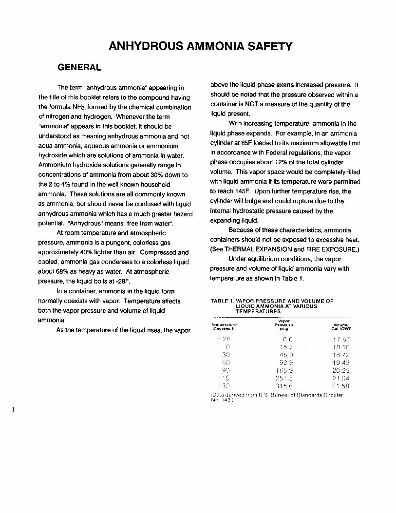
1

2

3

4

5

6

7
8

9
10
11
VOGT® TUBE-ICE® MACHINE
BASIC PRODUCT WARRANTY Vogt Tube Ice LLC, hereinafter referred to as SELLER, warrants to the original Purchaser from SELLER or the original end-user, hereinafter
referred to as PURCHASER, every Vogt® Tube-Ice® Machine Model
P24A, P24F, P24AL, P24ALOF P24FL, P34A, P34F, P34FL, P34AL,
P34ALOF and packaged high side Models P24AHS, P24FHS, P34AHS
and P34FHS to be free from defects in material and workmanship, if properly installed, maintained and operated, for a period of 12 months from date of original installation or 12 months from date of shipment from SELLER’S plant if SELLER does not have an accepted start-up form on file. SELLER’S obligation under this warranty shall be strictly limited, at SELLER’S option, to: (i) repairing or furnishing replacement parts on an exchange basis, F.O.B. Louisville, Kentucky, without charge to PURCHASER those parts proven defective upon examination by SELLER; or (ii) issuing written authorization for PURCHASER or its agents to replace or repair, without charge to PURCHASER, those parts proven defective upon examination by SELLER; or (iii) in discharge of SELLER’S maximum liability herewith, refunding all monies paid by PURCHASER to SELLER for the product and, at discretion of SELLER, having the product removed and returned to SELLER at PURCHASER’S expense. All transportation charges relative to corrective work or defective parts or replacement parts shall be borne by PURCHASER. PURCHASER shall give SELLER immediate notice upon discovery of any defect. The undertaking of repairs or replacement by PURCHASER or its agents without SELLER’S written consent shall relieve SELLER of all responsibility herewith. Any alteration in material or design of SELLER’S product or any component parts thereof by PURCHASER or others without written authorization by SELLER voids all obligations of SELLER regarding the product and any associated warranty herein stated or implied. SELLER’S sole liability shall be exclusively as set forth herein, and SELLER shall not be liable for any incidental or consequential damages due to its breach of any warranty herein contained, or otherwise. Without limitation to the foregoing, in no event shall SELLER be liable for the loss of use of the product or for the loss of use of any other product, process, plant, equipment, or facilities of the PURCHASER whether partially or wholly due to defects in material and/or workmanship and/or design of SELLER’S product, and in no event shall SELLER be liable for removal of appurtenances or incidentals such as connections,
pipework and similar items of obstruction or for any cost brought about by the necessity of removing the product from its point of installation.
SELLER DOES NOT MAKE AND DOES NOT AUTHORIZE ANY
OTHER PERSON TO MAKE ANY WARRANTY OF ANY KIND
WHATSOEVER, EXPRESS OR IMPLIED, ORALLY OR IN WRITING,
OTHER THAN AS SPECIFICALLY STATED HEREIN; AND THERE ARE
NO WARRANTIES OF MERCHANTABILITY AND/OR FITNESS FOR A
PARTICULAR PURPOSE WHICH EXCEED THE OBLIGATIONS AND
WARRANTIES SPECIFICALLY STATED HEREIN. Parts furnished without charge as replacements for original parts under warranty are warranted only for that period of time during which the original parts warranty is effective. Damage to any component due to water quality is specifically excluded from this warranty.
EXTENDED WARRANTY At the termination of the Basic Product Warranty period above, SELLER hereby extends this warranty for one additional year to cover the
CIRCULATING WATER TANK AND CUTTER ASSEMBLY, EXCLUDING
THE CUTTER BEARINGS AND DRIVE TRAINS.
LIFETIME WARRANTY* This component warranty is further extended for the life of the machine to cover the EVAPORATOR (FREEZER). Damage to evaporator tubes as a result of expansion caused by re-freezing of ice or corrosion damage due to water quality is specifically excluded.
The Extended Warranty applies only to VOGT TUBE-ICE MACHINE
MODELS P24A, P24F, P24AL, P24ALOF, P24FL, P34A, P34F, P34FL,
P34AL, and P34ALOF for the exclusive benefit of PURCHASER, as defined above. All other obligations, terms, conditions, exclusions and limitations of the Basic Product Warranty apply to the Extended and Lifetime Warranty.
*“Lifetime” is defined as 25 years. Vogt® and Tube-Ice® are registered
trademarks of Vogt Tube-Ice, LLC, 1000West Ormsby Ave., Louisville, Kentucky 40210
2000