turbine meter rq with universal smart transmitter ust and...
TRANSCRIPT

Bopp & Reuther Messtechnik GmbH Am Neuen Rheinhafen 4 67346 Speyer Deutschland
Telefon: +49 (6232) 657-0 Fax: +49 (6232) 657-505 [email protected] www.bopp-reuther.de
A-EN-02412-D0Rev.E 11/2013 Page 1 of 35
Turbine Meter RQ
with Universal Smart Transmitter UST
and HART® Communication EEx d and EEx de - series
Operating manual

Turbine meter RQ with UST, with HART® Communication EEx d and EEx de Operating manual
Page 2 of 35 Subject to change. A-EN-02412-D0Rev.E Bopp & ReutherMesstechnik GmbH
Table of Contents
Introduction 4
I. Transport, Delivery, Storage 4
II. Warranty 4
III. General Notes on Safety 4
1 Notes 5
1.1 Intended Use 5 1.2 Attention 5 1.3 Personnel for Installation, Start-up and Operation 5
1.3.1 Start-Up 6 1.3.2 Factory settings 6
1.4 Repairs, Hazardous Media 6 1.5 Technical Changes 7
1.5.1 Delivery 7
2 System 7
2.1 Measuring Principle 7 2.2 Measured Quantity 7 2.3 Measuring Range 8
3 Output 9
3.1 Output signal 9 3.1.1 Analog current output 9 3.1.2 Pulse Output 9
3.2 Load 10 3.3 Electrical and Thermal Safety Data 11
4 Mounting and Installation 12
4.1 General Information 12 4.2 Installation 13 4.3 Mounting of the Sensors 13
4.3.1 In- and Outlet Sections 13 4.3.2 Flow Straigthener 13 4.3.3 Pressure- and Temperature Compensation 13
4.4 Replacement of measuring system and/or bearings 14 4.4.1 Series 1 14 4.4.2 Series 2 15
5 Electrical Connections 16
5.1 Power Supply 16 5.2 Operation with the Software PACTware 17
6 Display and User Interface 18
6.1 General Information 18 6.2 LCD Display 18 6.3 Operation with HART® communication 19
6.3.1 PACTware 19 6.3.2 HART® Communicator 19
6.4 Instrument Functions and HART® Parametrisation 19 6.4.1 Measurement Values 19 6.4.2 Output 19 6.4.3 Device Parametrisation 20 6.4.4 Dialog / Functions 21 6.4.5 HART® 21
6.5 Checking the Maximum Output Frequency of the Pulse Output 22
7 Dimensions and Weights 24

Operating manual Turbine meter with UST, with HART® Communication EEx d and EEx de
Bopp & Reuther Messtechnik GmbH
A-EN-02412-D0Rev.E Subject to change. Page 3 of 35
7.1 Dimensions of Various Meters of the Series 24 7.1.1 Design/Dimensions Turbine Meters 24 7.1.2 Design/Dimensions In-/Outlet Pipe Section 25
8 Technical Data 26
8.1 Material 26 8.1.1 Turbine Meter 26 8.1.2 In-/Outlet section 26
8.2 Process Connection 26 8.3 Environmental Conditions 26
8.3.1 Ambient Temperature 26 8.3.2 Storage Temperature 26 8.3.3 Climatic Category 26 8.3.4 Degree of Protection 26 8.3.5 Electromagnetic Compatibility 26
8.4 Process Conditions 26 8.4.1 Viscosity Range 26 8.4.2 Media Temperature Range 26
8.5 Characteristic Values 27 8.5.1 Accuracy 27 8.5.2 Repeatability 27 8.5.3 Response Time 27 8.5.4 Turn-On Drift 27 8.5.5 Long Term Drift 27 8.5.6 Influence of Ambient Temperature 27
9 Certificates and Licenses 27
10 Standards and Guidelines 27
11 Appendix 28
11.1 Error Detection / Trouble Shooting 28 11.2 Error Detection in the Evaluation Electronics 28 11.3 Rotation of the display 31 11.4 Application examples 32
11.4.1 Application example 1 32 11.4.2 Application example 2 33 11.4.3 Application example 3 33
11.5 Certificate of non-objection for contractor 34 11.6 EC-Type Approval Certificate 94/9/EG USTD / USTE (May 2000) 35 11.7 EC-Type Approval Certificate 97/23/EG series RQ (July 2005) 35 11.8 EC-Conformity declaration (September 2013) 35

Turbine meter RQ with UST, with HART® Communication EEx d and EEx de Operating manual
Page 4 of 35 Subject to change. A-EN-02412-D0Rev.E Bopp & ReutherMesstechnik GmbH
Introduction
I. Transport, Delivery, Storage
Storage and Transport:
Protect devices against moisture, dirt, shock and damage.
Inspection of the Delivery:
Check shipment for completeness immediately upon receipt. Compare the instrument data with the infor-mation on the packing slip and the order documents.
Report any transport damage immediately after receipt of the delivery. Damages, which are reported later, will not be recognized.
II. Warranty
Scope and duration of warranty are defined in the contractual terms of delivery. Any warranty claims require proper installation and start-up of the devices according to the applicable oper-ating instructions. The required installation, putting into operation and servicing work may only be performed by qualified and authorized personnel. The evaluation electronics use CMOS chips. Therefore, when the electronics casing is opened, static elec-tricity discharges must be avoided. These can damage the evaluation electronics. Bopp & Reuther Mess-technik GmbH is not liable for damages, which are caused either indirectly or directly by improper handling.
For the transport of electronic assembly groups antistatic transport containers are to be used.
III. General Notes on Safety
Read and observe the operating instructions carefully and keep them in a safe place. Only qualified personnel may carry out installation. ElexV regulations as well as generally accepted technical rules and the operating instructions installations must be observed. Bopp & Reuther Messtechnik GmbH decline any liability for damages due to improper handling, use, installation and servicing of the devices. Check suitability of material of counter when using it with corrosive media. Put defective devices out of operation immediately.
Symbols used
Warning! Failure to observe this warning can lead to injury of persons or a security risk.
Attention! Non-compliance can lead to faulty operation or damage to the device.

Operating manual Turbine meter with UST, with HART® Communication EEx d and EEx de
Bopp & Reuther Messtechnik GmbH
A-EN-02412-D0Rev.E Subject to change. Page 5 of 35
1 Notes
1.1 Intended Use
The turbine meter is used to measure flow and volume of liquid media of low and medium viscosity such as:
crude oils
mineral oils
acids
alkaline solutions
solvents
water
liquefied gases
liquid food and beverages Turbine meters of the RQ series are available with nominal widths of 10 to 300. According to nominal width it may be used for PN6 to PN 320, the maximum temperature of the measured media may be up to 250 °C depending on the model. The Universal Smart Transmitter UST represents new evaluation electronics of the latest technical design. The UST processes the electrical signals from the various sensor systems and displays the values of volume and flow. The flow is put out on an analog 4 to 20 mA current loop (according to NAMUR NE 43). The UST is equipped with two-wire technology serving as its power supply. In addition there is a separate pulse output according to NAMUR. Due to the integrated electronics, HART®-communication with a control room or with a portable data terminal on-site is feasible using the analog current loop. All relevant operating or configuration data can be read out from the transmitter or stored into the transmitter. Thus the measurement tasks of the turbine flow meter is functionally optimized and can be set directly on-site or via a control system. Always state ID-number of the meter if you have any questions or wish to order spare parts.
1.2 Attention
The turbine meter RQ is state of the art and has been designed for maximum operational safety. It has been carefully checked and is delivered in perfect condition as regards safety. Improper use respectively use in conditions the device has not been explicitly certified for may incur danger. Mind the warnings in the operating instructions!
1.3 Personnel for Installation, Start-up and Operation
Only qualified and authorized personnel may perform installation, mounting, electrical installation, putting into operation, servicing and operation. Any such person must have read and understood the operating instructions and follow the instructions therein.
Check the material’s resistance of all parts coming into contact with the measured media when using the device with aggressive media (gaskets, turbine wheels, etc.).
Make sure to observe your country’s specific regulations and provisions.

Turbine meter RQ with UST, with HART® Communication EEx d and EEx de Operating manual
Page 6 of 35 Subject to change. A-EN-02412-D0Rev.E Bopp & ReutherMesstechnik GmbH
1.3.1 Start-Up
Vent pipeline by means of a vent valve placed upstream of the Turbine Meter.
Attention! Large amounts of air or gas cause excessive acceleration of the rotor and may damage the me-ter or the bearings.
Fill pipeline by means of a by-pass line – slowly open shut off valve.
1.3.2 Factory settings
The counters’ factory pre-settings correspond to the conditions of operation stated in the order form. Pre-set values are specified in the configuration data sheet.
1.4 Repairs, Hazardous Media
Before sending the turbine meter to Bopp & Reuther Messtechnik make sure to observe the following: Attach a note describing the malfunction, state the field of application as well as the chemical/physical
properties of the measured media. Remove all residues of the media and pay special attention to sealing grooves and slits. This is of ex-
treme importance if the medium is hazardous to health, i.e. when it is caustic, toxic, carcinogenic or radi-oactive, etc.
Please do not return the device if you are not perfectly sure that all media hazardous to health have been cleaned off.
Costs incurred due to inadequate cleaning of the device and possible costs for disposal and/or personal injuries (causticity etc.) will be billed to the operating company.
Please ask our customer service for help and advice if your turbine meter does not work properly: Bopp & Reuther Messtechnik GmbH
Service Am Neuen Rheinhafen 4 D-67346 Speyer Phone: +49 6232 657-402 Fax : +49 6232 657-561
Bopp & Reuther Messtechnik GmbH Münchener Str. 23 85123 Karlskron Gewerbegebiet Brautlach, an der B 13 Phone: +49 8450 928330 Fax: +49 8450 928332

Operating manual Turbine meter with UST, with HART® Communication EEx d and EEx de
Bopp & Reuther Messtechnik GmbH
A-EN-02412-D0Rev.E Subject to change. Page 7 of 35
1.5 Technical Changes
All dimensions, weights and technical data given are subject to change without prior notice as Bopp and Reuther Messtechnik GmbH is continuously looking for further improvement and development and striving for quick and unbureaucratic implementation. 1.5.1 Delivery
Depending on the series the turbine wheel meters are delivered as described below:
Series 1
DN 10 ... 65 One part, completely mounted - Check the smooth running of the rotor
Blowing your breath through the meter is sufficient - Counter ready to be mounted
Series 2
DN 80 ... 300 Several parts, mounting to be performed on-site 2 System
The UST is equipped with two-wire technology serving as its power supply. Due to the integrated electronics, HART®-communication with a control room or with a portable data terminal on-site is feasible using the ana-log current loop. All relevant operating or configuration data can be read out from the transmitter or stored into the transmitter. Thus the measurement tasks of the turbine flow meter is functionally optimized and can be set directly on-site or via a control system.
2.1 Measuring Principle
The turbine meter is an indirect volume meter. Its main component is an axial turbine wheel turning freely in the flowing liquid. The turbine wheel is rotated by the liquid and spins at a rotational speed, which corresponds to the average flow velocity of the liquid in the free cross section of the turbine flow meter. The rotational movement is transmitted through the casing wall in a non-interacting manner to the UST, which supplies a 4 to 20mA sig-nal, proportional to the volumetric rate of flow, and displays the respective value directly on-site.
2.2 Measured Quantity
The number of revolutions of the turbine wheel meter is directly proportional to the volumetric rate of flow with the number of revolutions being proportional to the volume that has passed through the meter.

Turbine meter RQ with UST, with HART® Communication EEx d and EEx de Operating manual
Page 8 of 35 Subject to change. A-EN-02412-D0Rev.E Bopp & ReutherMesstechnik GmbH
2.3 Measuring Range
Series 1 Nominal width Flow rate
Qmax [m³/h]
Meter factor
Imp/dm³
Frequen-cy
fmax [Hz]
Pulses per revo-
lution DN ANSI
10 - 1,5 1750 730
4
15 ½ 6 310 517
20 ¾ 12 170 567
25 1 18 105 525
32 1¼ 30 58 467
40 1½ 42 22 257
50 2 72 12,4 248
65 2½ 120 6 200
Series 2
Nominal width Flow rate
Qmax [m³/h]
Meter factor
Imp/dm³
Frequen-cy
fmax [Hz]
Pulses per revo-
lution DN ANSI
80 3 180 15 750 12
100 4 300 6 500 10
150 6 600 3,4 567 18
200 8 1200 1,84 613 24
250 10 1800 1,24 600 40
300 12 2400 0,78 520 44

Operating manual Turbine meter with UST, with HART® Communication EEx d and EEx de
Bopp & Reuther Messtechnik GmbH
A-EN-02412-D0Rev.E Subject to change. Page 9 of 35
3 Output
3.1 Output signal
The output signals are available as analog output, as current pulse output with two-wire technology, and as separate NAMUR pulse output. 3.1.1 Analog current output
The flow is a standard signal output of 4-20mA. Initial value, final value and attenuation can be pre-set. The analog current output transmits the flow value measurement from 4-20mA. 3.1.2 Pulse Output
Two different types of pulse outputs (current pulse or NAMUR pulse) are available for the transmission of the volume flow. The output can either be set as original pulse without evaluation or as scaled pulse with se-lectable pulse width. This applies to both types of pulse outputs. The pulse value can be scaled with an addi-tional factor regarding the internal meter increments. The original pulse has a set pulse width of 0.5 ms. The maximum output frequency is 1 kHz. The pulse width for the scalable pulse can be selected. a) Two-Wire Current Pulse Output:
On the two-wire current loop, the output signal is a current pulse between 4mA = low and 20mA = high. This pulse output can be activated by means of a double actuator on the power supply circuit board. The current pulse is provided at terminal 1 and 2 of the current loop. (The analog signal of 4 to 20mA for the volume flow is no longer available). HART®-communication is restricted.
Reset-Button RESET
DISPLAY
l / minQ:
lV:
2 - wire
0 0 0 0 0 1 2 57 6 5 4 3 2 1 0
V2 Q V1Display-button
Display
Double Actuator with Identifier
b) Pulse Output according to NAMUR
The NAMUR-output pulse is provided at terminals 3 and 4. The signals are structured according to the Euro-pean standard, EN 60947-5-6.
Turbine meter RQ with UST, with HART® Communication EEx d and EEx de Operating manual
Page 10 of 35 Subject to change. A-EN-02412-D0Rev.E Bopp & ReutherMesstechnik GmbH
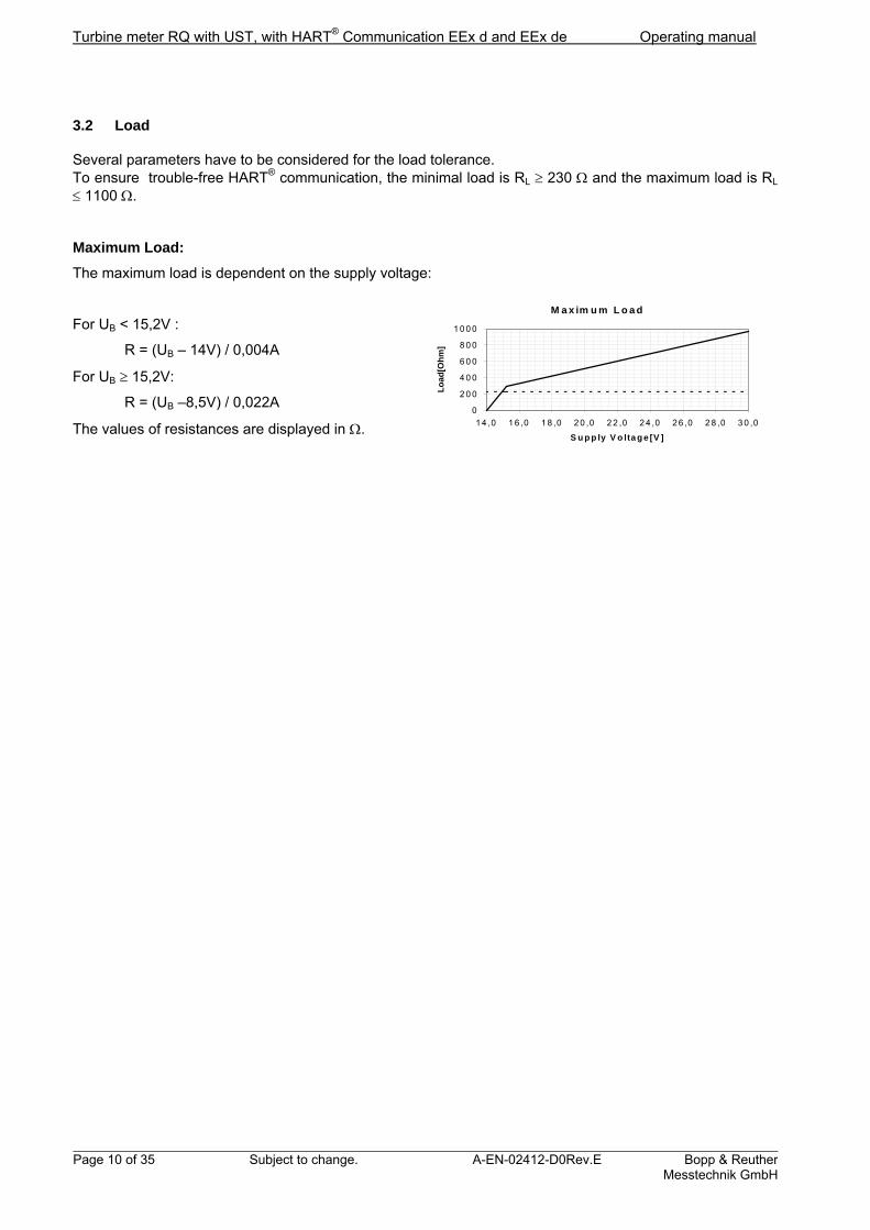
3.2 Load
Several parameters have to be considered for the load tolerance. To ensure trouble-free HART® communication, the minimal load is RL 230 and the maximum load is RL 1100 .
Maximum Load:
The maximum load is dependent on the supply voltage:
For UB < 15,2V :
R = (UB – 14V) / 0,004A
For UB 15,2V:
R = (UB –8,5V) / 0,022A
The values of resistances are displayed in .
M a x im u m L o a d
0
2 0 0
4 0 0
6 0 0
8 0 0
1 0 0 0
1 4 ,0 1 6 ,0 1 8 ,0 2 0 ,0 2 2 ,0 2 4 ,0 2 6 ,0 2 8 ,0 3 0 ,0
S u p p ly V o lta g e [V ]L
oad
[Oh
m]

Operating manual Turbine meter with UST, with HART® Communication EEx d and EEx de
Bopp & Reuther Messtechnik GmbH
A-EN-02412-D0Rev.E Subject to change. Page 11 of 35
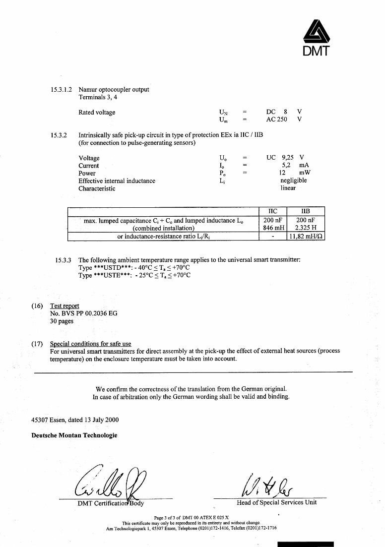
3.3 Electrical and Thermal Safety Data
1. Power supply and signal circuits (terminals 1+2)
Reference Voltage UN = DC 24V UM = AC 250V Reference Amperage IN = 4-20 mA Nominal Output PN = 600 mW
2. NAMUR opto-coupler output (terminals 3+4) Reference voltage UN = DC 8V UM = AC 250V
3. Sensor circuit with protection type EEx ia IIC (to be connected to pulse emitting sensors). Voltage Uo = UC 9,25 V Amperage Io = 5,2 mA Output Po = 12 mW Internal inductivity Li = negligible Charcteristic line linear
IIC IIB Max. concentrated capacity Ci + Co and concentrated inductivity Lo (mixed connection)
200 nF 846 mH
200 nF 2,325 H
Relation inductivity-resistance Li/Ri - 11,82 mH/ 4. The ambient temperature for the Universal Smart Transmitter is: Type ***USTD***: -40°C Ta +70°C (EEx d - variant) Type ***USTE***: -25°C Ta +70°C (EEx de - variant)
Turbine meter RQ with UST, with HART® Communication EEx d and EEx de Operating manual
Page 12 of 35 Subject to change. A-EN-02412-D0Rev.E Bopp & ReutherMesstechnik GmbH
4 Mounting and Installation
4.1 General Information
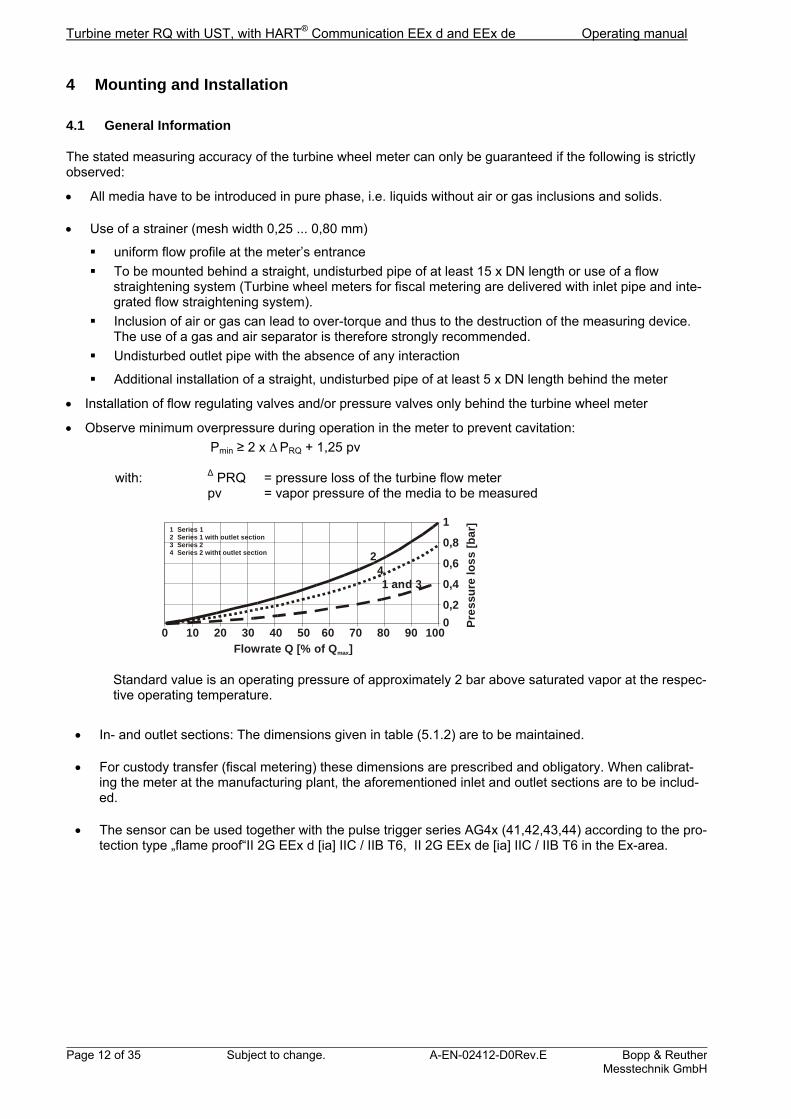
The stated measuring accuracy of the turbine wheel meter can only be guaranteed if the following is strictly observed:
All media have to be introduced in pure phase, i.e. liquids without air or gas inclusions and solids.
Use of a strainer (mesh width 0,25 ... 0,80 mm)
uniform flow profile at the meter’s entrance
To be mounted behind a straight, undisturbed pipe of at least 15 x DN length or use of a flow straightening system (Turbine wheel meters for fiscal metering are delivered with inlet pipe and inte-grated flow straightening system).
Inclusion of air or gas can lead to over-torque and thus to the destruction of the measuring device. The use of a gas and air separator is therefore strongly recommended.
Undisturbed outlet pipe with the absence of any interaction
Additional installation of a straight, undisturbed pipe of at least 5 x DN length behind the meter
Installation of flow regulating valves and/or pressure valves only behind the turbine wheel meter
Observe minimum overpressure during operation in the meter to prevent cavitation:
Pmin ≥ 2 x ∆ PRQ + 1,25 pv
with: ∆ PRQ = pressure loss of the turbine flow meter pv = vapor pressure of the media to be measured
0 10 20 30 40 50 60 70 80 90 1000
0,2
0,4
0,6
0,8
1
Pre
ssu
re lo
ss
[bar
]
Flowrate Q [% of Q ]max
241 and 3
1 Series 12 Series3 Series4 Series
1 with outlet section 2 2 witht outlet section
Standard value is an operating pressure of approximately 2 bar above saturated vapor at the respec-tive operating temperature.
In- and outlet sections: The dimensions given in table (5.1.2) are to be maintained.
For custody transfer (fiscal metering) these dimensions are prescribed and obligatory. When calibrat-ing the meter at the manufacturing plant, the aforementioned inlet and outlet sections are to be includ-ed.
The sensor can be used together with the pulse trigger series AG4x (41,42,43,44) according to the pro-tection type „flame proof“II 2G EEx d [ia] IIC / IIB T6, II 2G EEx de [ia] IIC / IIB T6 in the Ex-area.

Operating manual Turbine meter with UST, with HART® Communication EEx d and EEx de
Bopp & Reuther Messtechnik GmbH
A-EN-02412-D0Rev.E Subject to change. Page 13 of 35
4.2 Installation
Flush and purge the pipe for cleaning purposes. When doing so, replace the turbine wheel meter with a suitable piece of piping
When mounting the turbine wheel meter including the inlet pipe please pay special attention to
direction of flow
installation position:
- series 1 (DN15-DN65) horizontally or vertically
- series 2 (DN80-DN300) horizontally
Use appropriate flange gaskets and make sure that they are correctly mounted (should not jut out into the pipe).
4.3 Mounting of the Sensors
4.3.1 In- and Outlet Sections
To ensure best measurement results, the velocity profile in the inlet section needs to be a fully turbulent flow, free of any disturbances.
The in- and outlet sections must have a minimum length of: Inlet section: minimum length of 10 x nominal width Outlet section: minimum length of 5 x nominal width 4.3.2 Flow Straigthener
Installation of flow rectifiers reduces the impact of disturbances. Thus the length of the inlet section can be reduced, too. To achieve highly accurate measurement results the impact of flow rectifiers must be taken into account during the calibration process. 4.3.3 Pressure- and Temperature Compensation
If pressure- and temperature measuring points are required, these must be placed in the outlet section be-hind the meter housing (distance: 3 x nominal width for the pressure and 5 x nominal width for temperature measuring point).
Turbine meter RQ with UST, with HART® Communication EEx d and EEx de Operating manual
Page 14 of 35 Subject to change. A-EN-02412-D0Rev.E Bopp & ReutherMesstechnik GmbH
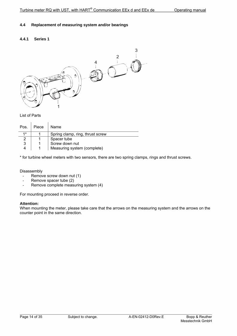
4.4 Replacement of measuring system and/or bearings
4.4.1 Series 1
42
3
1 List of Parts
Pos. Piece Name
1* 1 Spring clamp, ring, thrust screw 2 1 Spacer tube 3 1 Screw down nut 4 1 Measuring system (complete)
* for turbine wheel meters with two sensors, there are two spring clamps, rings and thrust screws. Disassembly
- Remove screw down nut (1) - Remove spacer tube (2) - Remove complete measuring system (4)
For mounting proceed in reverse order. Attention: When mounting the meter, please take care that the arrows on the measuring system and the arrows on the counter point in the same direction.

Operating manual Turbine meter with UST, with HART® Communication EEx d and EEx de
Bopp & Reuther Messtechnik GmbH
A-EN-02412-D0Rev.E Subject to change. Page 15 of 35
4.4.2 Series 2
List of Parts
Pos. Pieces Name
2 2 Bearing joint 13 1 Impeller 7 1 Bearing Axle 8 4 Cylinder head screw 9 1 Counter bearing
10 4 Cylinder head screw 14 1 Bearing bush 15 4 Cylinder head screw 24* 1 Thrust screw 22* 1 Ring 23* 1 Spring clamp
* for turbine wheel meters with two sensors, there are two spring clamps, rings and thrust screws (positions 22, 23 and 24). Disassembly
- position the meter in such a way that it rests on its inlet flange - loosen and remove rear cylinder head screws (5) plus washers (4) - remove rear bearing joint (2) - remove impeller (13) - loosen and remove front cylinder head screws (5) plus washers (4) - remove rear bearing joint (2) - loosen and remove cylinder head screws (10, 15) - remove counter bearing (9) and bearing bush (14) - loosen cylinder head screws (8) - remove bearing axle (7)
For mounting the spare parts proceed in reverse order.
Attention: Please take care that the positioning of the bearing joints (marks „0“ and „1“) corresponds to the marks on the housing.
Turbine meter RQ with UST, with HART® Communication EEx d and EEx de Operating manual
Page 16 of 35 Subject to change. A-EN-02412-D0Rev.E Bopp & ReutherMesstechnik GmbH
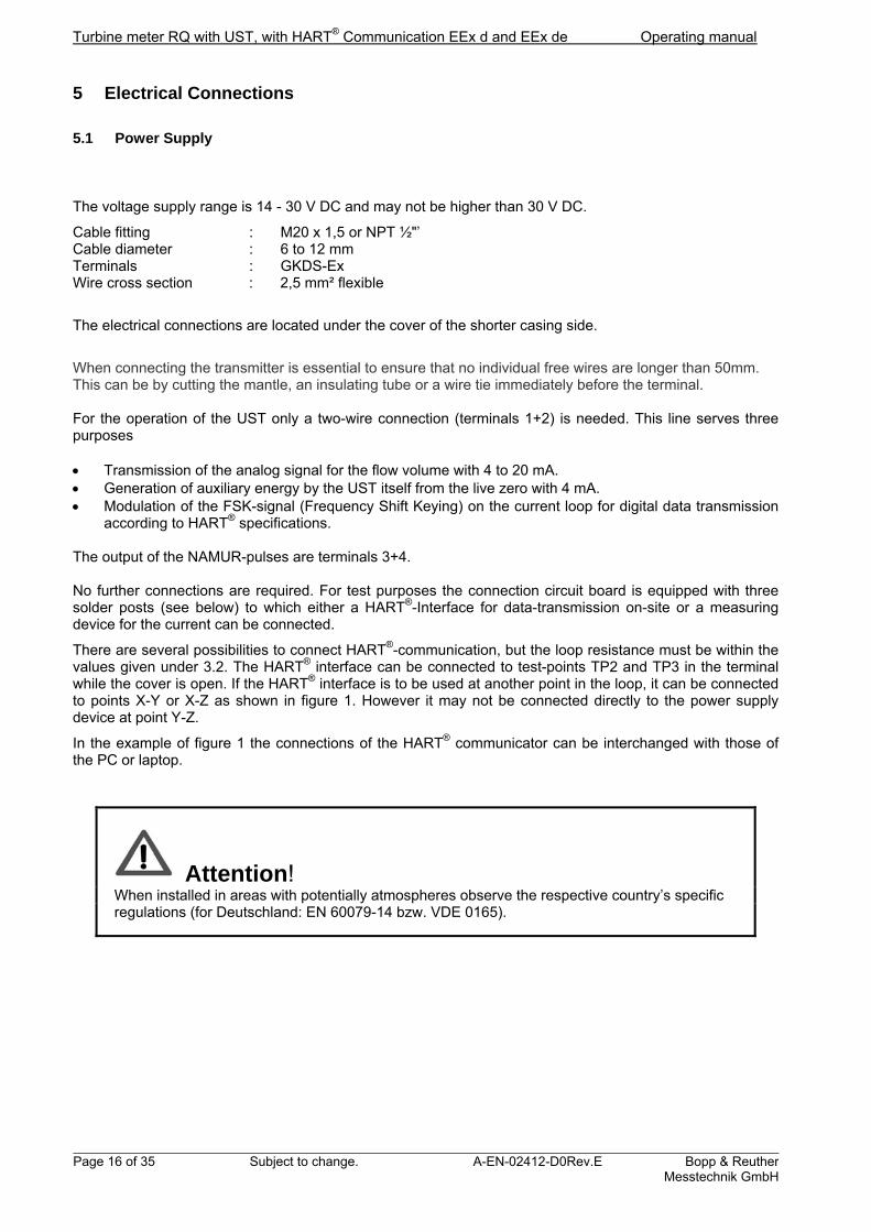
5 Electrical Connections
5.1 Power Supply
The voltage supply range is 14 - 30 V DC and may not be higher than 30 V DC.
Cable fitting : M20 x 1,5 or NPT ½"’ Cable diameter : 6 to 12 mm Terminals : GKDS-Ex Wire cross section : 2,5 mm² flexible
The electrical connections are located under the cover of the shorter casing side.
When connecting the transmitter is essential to ensure that no individual free wires are longer than 50mm. This can be by cutting the mantle, an insulating tube or a wire tie immediately before the terminal. For the operation of the UST only a two-wire connection (terminals 1+2) is needed. This line serves three purposes Transmission of the analog signal for the flow volume with 4 to 20 mA. Generation of auxiliary energy by the UST itself from the live zero with 4 mA. Modulation of the FSK-signal (Frequency Shift Keying) on the current loop for digital data transmission
according to HART® specifications. The output of the NAMUR-pulses are terminals 3+4. No further connections are required. For test purposes the connection circuit board is equipped with three solder posts (see below) to which either a HART®-Interface for data-transmission on-site or a measuring device for the current can be connected.
There are several possibilities to connect HART®-communication, but the loop resistance must be within the values given under 3.2. The HART® interface can be connected to test-points TP2 and TP3 in the terminal while the cover is open. If the HART® interface is to be used at another point in the loop, it can be connected to points X-Y or X-Z as shown in figure 1. However it may not be connected directly to the power supply device at point Y-Z.
In the example of figure 1 the connections of the HART® communicator can be interchanged with those of the PC or laptop.
Attention! When installed in areas with potentially atmospheres observe the respective country’s specific regulations (for Deutschland: EN 60079-14 bzw. VDE 0165).

Operating manual Turbine meter with UST, with HART® Communication EEx d and EEx de
Bopp & Reuther Messtechnik GmbH
A-EN-02412-D0Rev.E Subject to change. Page 17 of 35
Figure 1 shows the connection options described in 5.1
5.2 Operation with the Software PACTware
To operate the UST with the PACTware operating software a HART-Interface is required. The Interface transforms the level of the RS232 interface or USB- interface into a frequency shift keying (FSK) signal. The interface can also be installed permanently. The connection is set up as shown in figure 1.
Warning! The use of a PC or a Laptop and HART - Interface in an EX - Zone re-quires special approval certificates.
RQ with UST
NAMUR-pulses
Test current
loop
Transmitter power supply HART 14 … 30 V
PACTware

Turbine meter RQ with UST, with HART® Communication EEx d and EEx de Operating manual
Page 18 of 35 Subject to change. A-EN-02412-D0Rev.E Bopp & ReutherMesstechnik GmbH
6 Display and User Interface
6.1 General Information
The meters are set before delivery according to the operating conditions specified in your order. For further information please refer to attached configuration data sheet. For configuration respectively operation of the transmitter you have the choice between following two options: 1. HART® communication 2. On-site control of simple functions by means of a switching magnet.
6.2 LCD Display
The values of the flow, of the sum and of the reset meter can be displayed on the 8-digit LCD display. The selection of the displayed value can be chosen via the switching magnet, which is operated by touching the “Display” button below the display window. The value chosen is identified by a mark below the decimal point. After activating the button, the display switches as shown in the overview below:
reset thereset counter
touch„Display“
touch„Display“
touch„Display“
automatic reset
flow rate8 8 8 8 8 8 8 8
reset counter8 8 8 8 8 8 8 8
sum counter8 8 8 8 8 8 8 8
touch„Display“
flow rate8 8 8 8 8 8 8 8
reset counter8 8 8 8 8 8 8 8
sum counter8 8 8 8 8 8 8 8
alternating displaytouch„Reset“ > 3 sek
In the alternating display mode all three values are shown sequentially in preset time intervals. The “resetting“ of the reset meter can only be effected while this specific value is being displayed. The button must be pressed for at least three seconds. For better legibility the display circuit board may be rotated me-chanically by 90° or 180° (see chapter 11.3).

Operating manual Turbine meter with UST, with HART® Communication EEx d and EEx de
Bopp & Reuther Messtechnik GmbH
A-EN-02412-D0Rev.E Subject to change. Page 19 of 35
6.3 Operation with HART® communication
6.3.1 PACTware
To operate the Turbine Meter with UST the PACTware software can be used. PACTware is a configuration- and operation software that provides all UST functions via HART® communication. The individual functions are listed in chapter 6.4 “Instrument Functions”. A PC is required for the use of PACTware with the following minimum system requirements:
Pentium III 400 Windows XP, VISTA or 7 Hard drive with 100MB free space The software is free to download: www.bopp-reuther.de UST is connected to the RS232 or USB-interface of the PC using a HART interface (see chapter 5.2).
6.3.2 HART® Communicator
A HART communicator (e.g. handheld HC-375 from Emerson) is another operating element which can be used. The operating functions for HC-375 are defined in a DD (Device Description). Using the HC-375 it is possible to operate or configure the OI on-site. The connection is described in chapter 5. The Device Description Language (DD) can be downloaded from the Internet (HART® Foundation www.hartcomm.org).
6.4 Instrument Functions and HART® Parametrisation
6.4.1 Measurement Values
Volume Flow: Display of the actual volumetric flow in the selected unit.
Flow Unit: Units to define the volumetric flow. Options are: ℓ/s, ℓ/min, ℓ/h, m3/s, m3/min, m3/h, gal/s, gal/min, gal/h, impgal/s, impgal/min, impgal/h, ft³/s, ft³/min, ft³/h.
Reset Meter: The Reset Meter adds the volume values measured in the selected unit and can be reset. After a power outage the meter is automatically reset to zero.
Sum Meter: The Sum Meter adds the volume values measured in the selected unit. This meter can only be reset when being serviced. The value displayed does not change after a power outage.
Unit of Volume: This unit defines the value of the reset and the sum meter. If this unit is changed during operation, the new volume units are added to the old volume units. Therefore please set the meters to zero before changing the unit. Choose between l, m³, gal, impgal, ft³.
Frequency history: The maximum sensor frequency is recorded. The display can not be set to zero or altered (drag hand function) and remains the same after a power outage.
Pulse Meter: The Pulse Meter displays the number of all original pulses without evaluation. The display can not be set to zero and remains the same after a power outage.
6.4.2 Output
Final Value of Measurement Range: The final sensor value is pre-set in the UST of all meters regardless of the series. This value must not be exceeded during operating.
Initial Value of Measurement Range: The initial sensor value is pre-set in the UST of all meters regardless of the series. Below this value there is no defined error curve.

Turbine meter RQ with UST, with HART® Communication EEx d and EEx de Operating manual
Page 20 of 35 Subject to change. A-EN-02412-D0Rev.E Bopp & ReutherMesstechnik GmbH
Minimum Measurement Span: The minimum measurement span can be set as desired within the measurement range. The minimum measurement span should be maintained as a lower value can lead to fluctuations of the output current.
Initial Value of Current Output: The desired initial flow value in the selected unit is assigned to the initial value of 4 mA. Usually the flow value of zero is assigned to 4 mA.
Final Value of Current Output: The desired final flow value in the selected unit is assigned to the final value of 20 mA.
Attenuation: Attenuation effects the output current and the flow display. Choose a value between 1s and 200s. The resolution is about 1s.
Current Alarm: When the current alarm is activated the current output is set to 22 mA, as soon as a current alarm occurs.
Pulse Output: The pulse output can either be set as original pulse with the frequency und pulse value corresponding to the K-factor of the meter or as a scaled pulse with a pulse value and pulse width that can be scaled in decade steps.
6.4.3 Device Parametrisation
Sensor Type: Indicates to which sensor type (Wiegand, Reed or inductive pick-up) the electronics are set.
KP Factor: The test factor is a constant that is specific for the individual device and may not be changed. It is deter-mined during the calibration process, the unit is pulses/l.
KK Factor: The correction factor is without dimension and serves to adjust the error curve to various media. The fac-tor can be adjusted by the servicing staff. Thus viscosity correction is possible.
KB Factor: The operating factor is the product of the test and correction factor. This factor is not saved in the UST but calculated and displayed by the PACTware.
Display Mode: The display can be switched from flow to reset meter and sum meter. The three values are shown alter-nately at intervals of about 2 seconds.
Pulse Value Factor: The value of the output pulses and of the meter are set using the pulse value factor Fw. Together with the selected unit the pulse value factor corresponds to the pulse value and to the increment of the meter.
Example: pulse value factor 0.1 means:
value
UnitFactor
l 1,0ˆ1 Ipulse
When the factor is set, the display automatically adjusts the decimal point accordingly so that the values can be read directly from the meter. The pulse value factor can be set as follows:
Pulse value factor 1 0.1 0.01 0.001
If this factor is changed during operation, the meters should be set to zero as otherwise mixing various volume evaluations will lead to incorrect figures. Please check that the maximum output frequency is not exceeded, which depends on the selected pulse width (see table “pulse width” below). If the output fre-quency is exceeded, the excessive pulses are counted into a buffer memory; the output is effected with a time delay.

Operating manual Turbine meter with UST, with HART® Communication EEx d and EEx de
Bopp & Reuther Messtechnik GmbH
A-EN-02412-D0Rev.E Subject to change. Page 21 of 35
Pulse Relation Factor: Using the pulse relation factor Fi the meter and the pulse output can be evaluated differently. The pulse relation factor is the relation of the value of the meter increment and the value of the pulse output. The standard setting is Fi=1, i.e. one increment on the meter corresponds to one pulse output. If the factor is set to Fi 1 the value of the pulse output is changed whereas the value of the meter re-mains unchanged. The maximum output frequency must be checked.
Pulse Width: Choose the pulse width according to the table below:
Pulse width 150 ms 50 ms 20 ms 10 ms
Maximum output frequency 3,3 Hz 10 Hz 25 Hz 50 Hz
This setting applies to both pulse outputs, i.e. current pulse and NAMUR pulse. The maximum output fre-quency has to be taken into account when choosing pulse value and pulse relation factor. 6.4.4 Dialog / Functions
Reset of the Reset Meter: The reset meter can be reset to zero at any time.
Reset of the Sum Meter: The sum meter may only be reset by our service staff. If the unit of the volume or the pulse value are changed, this meter has to be reset to zero.
Current Simulation: For testing serially connected devices a fixed output current may be set. After testing the current value 0 mA has to be entered to end the simulation.
Calibration of Current Output: The characteristic curve of the analog current output can be calibrated at 4 mA for the zero point and at 20 mA for the final value. Please note that the zero point has to be calibrated before the final value.
6.4.5 HART®
Software Version: The number indicates the version of the UST software.
Hardware Version: The number indicates the version of the UST hardware.
Polling Address: If the UST is to be installed for multi-drop application, a polling address from 1 – 15 must be entered. This means that a point-to-point connection with the desired address has to be configured beforehand. If the polling address is set to zero, the operation is analog.
Turbine meter RQ with UST, with HART® Communication EEx d and EEx de Operating manual
Page 22 of 35 Subject to change. A-EN-02412-D0Rev.E Bopp & ReutherMesstechnik GmbH
6.5 Checking the Maximum Output Frequency of the Pulse Output
To ensure that the maximum output frequency is not exceeded, observe the following:
For Fi=1, Fw ̂Wcount=Wpuls the following applies:
max
maxf
QFw
For Fi 1, Fw ̂Wcount the following applies:
iw Ff
QF
max
max
and
i
countpuls F
WW
Meaning of Formula Symbols:
Qmax: maximum flow
Second
selectedasunit
fmax: maximum output frequency. See table:
Pulse width 150 ms 50 ms 20 ms 10 ms
Maximum output frequency 3.3 Hz 10 Hz 25 Hz 50 Hz
Fw: pulse value factor
pulse value factor 1 0.1 0.01 0.001
Fi: pulse relation factor Wcount: counting value in l, m3, ...
Wpuls: pulse value in l, m3, ...
Operating manual Turbine meter with UST, with HART® Communication EEx d and EEx de
Bopp & Reuther Messtechnik GmbH
A-EN-02412-D0Rev.E Subject to change. Page 23 of 35
Calculation examples to check the scaled pulse output taking into account the maximum output fre-quency 1. Example
for a selected pulse width of 150 ms the maximum output frequency is fmax = 3.3Hz. - selected volume unit [ℓ] - maximum flow (e.g. RQ 20) Qmax = 3.3 ℓ/s The smallest possible pulse value factor is calculated as follows:
max
maxf
QFw = 3.3 / 3.3 = 1
According to the table (see page 23) for the pulse value factors Fw = 1 the next larger value or the same value must be selected. Thus the value of the meter and the pulse output is 1 ℓ and 1 ℓ per pulse.
2. The same meter data as in example 1 are assumed, but the value on the meter is to be one tenth of the value of the pulse output (meter is 10 times faster). A pulse relation factor of 0.1 needs to be set. The smallest possible pulse value factor is calculated as follows:
max
max
f
QFw x Fi = 3.3/3.3 x 0.1 = 0.1
For the pulse value factor Fw = 0,1 the next larger value or the same value must be selected. The pulse value of the pulse output is calculated as follows:
i
countpuls F
WW = 0.1 / 0.1 = 1 l (for Fi 1 ist Fw ̂Wcount)
Higher pulse values can be selected by setting the pulse value factor to a higher decimal level. Note: The maximum output frequency will be exceeded, if the pulse value factors are smaller than the calculated critical value.
Turbine meter RQ with UST, with HART® Communication EEx d and EEx de Operating manual
Page 24 of 35 Subject to change. A-EN-02412-D0Rev.E Bopp & ReutherMesstechnik GmbH
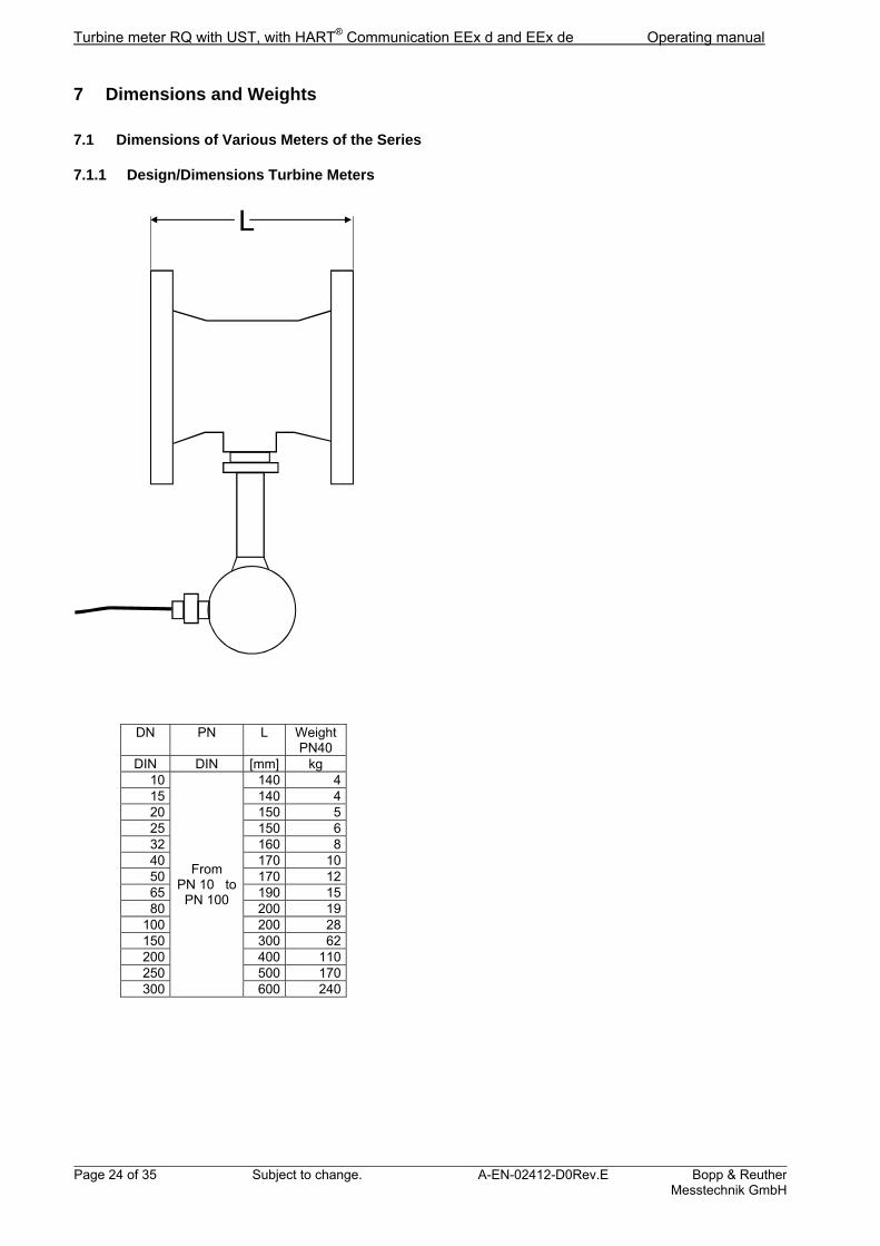
7 Dimensions and Weights
7.1 Dimensions of Various Meters of the Series
7.1.1 Design/Dimensions Turbine Meters
L
DN PN L Weight
PN40 DIN DIN [mm] kg
10
From PN 10 to
PN 100
140 4 15 140 4 20 150 5 25 150 6 32 160 8 40 170 10 50 170 12 65 190 15 80 200 19
100 200 28 150 300 62 200 400 110 250 500 170 300 600 240
Operating manual Turbine meter with UST, with HART® Communication EEx d and EEx de
Bopp & Reuther Messtechnik GmbH
A-EN-02412-D0Rev.E Subject to change. Page 25 of 35
Inlet pipe section with flow straightener
Outlet pipe section
Turbine meter RQ
Meter run
Approx. 100 mm for Ag 81, 82Approx. 350 mm for Ag 83picture with Ag 81
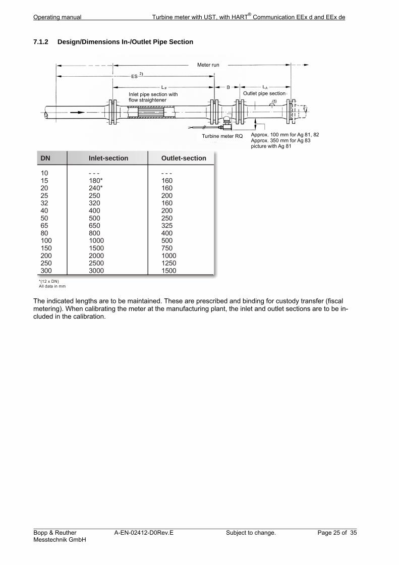
7.1.2 Design/Dimensions In-/Outlet Pipe Section
DN Inlet-section Outlet-section
10 - - - - - -15 180* 16020 240* 16025 250 20032 320 16040 400 20050 500 25065 650 32580 800 400100 1000 500150 1500 750200 2000 1000250 2500 1250300 3000 1500
*(12 x DN) All data in mm
The indicated lengths are to be maintained. These are prescribed and binding for custody transfer (fiscal metering). When calibrating the meter at the manufacturing plant, the inlet and outlet sections are to be in-cluded in the calibration.
Turbine meter RQ with UST, with HART® Communication EEx d and EEx de Operating manual
Page 26 of 35 Subject to change. A-EN-02412-D0Rev.E Bopp & ReutherMesstechnik GmbH
8 Technical Data
8.1 Material
8.1.1 Turbine Meter
Series 1 (DN15-65): stainless steel 1.4429, housing stainless steel 1.4425 Series 2 (DN80-DN300): Housing steel or stainless steel, cast or forged. More materials upon request (Hastelloy etc.) 8.1.2 In-/Outlet section
Material group Flanges Pipe Pipe bundle
DN 65 DN 80
F 1.4571 1.4571 1.4571
F 2 1.0425 1.0305 1.4571 1.0305
1.0432
Material
8.2 Process Connection
Flange: DN 10 – 300 (1/2“ – 12“) PN 6 – 320 Class 150 – 2500 in accordance with DIN 2501 or ANSI B16.5
8.3 Environmental Conditions
Avoid exposure of the electronics housing and the turbine wheel meter to sudden temperature changes. 8.3.1 Ambient Temperature
-10 °C up to +70 °C 8.3.2 Storage Temperature
RQ: -25 °C to +100 °C UST: -20 °C to +70 °C RQ with UST: -20 °C to +70 °C 8.3.3 Climatic Category
Class D IEC 654-1 8.3.4 Degree of Protection
IP 67 8.3.5 Electromagnetic Compatibility
In accordance with EMV-guideline 2004/108/EG, EN 61000-6-2, EN 61000-6-3, as well as NAMUR NE 21
8.4 Process Conditions
8.4.1 Viscosity Range
0,2 to 50 mPas 8.4.2 Media Temperature Range
Compact design -40...+70 °C Wall design -65...+180 °C Design for low or high temperature -196...+250 °C

Operating manual Turbine meter with UST, with HART® Communication EEx d and EEx de
Bopp & Reuther Messtechnik GmbH
A-EN-02412-D0Rev.E Subject to change. Page 27 of 35
8.5 Characteristic Values
8.5.1 Accuracy
High accuracy 0,15 % of reading over a reduced flow range Standard accuracy 0,25 – 0,3 % of reading for normal flow range The given values for the accuracy are for viscosities of 0,2 – 0,7 mPas. The accuracy depends on the viscosity, flow range and the requested nominal size. Please contact our sales engineers for specific information. 8.5.2 Repeatability
±0,02% of measured value 8.5.3 Response Time
1 s 8.5.4 Turn-On Drift
2 s 8.5.5 Long Term Drift
< 0.005% / year 8.5.6 Influence of Ambient Temperature
< 0.005% / °C
9 Certificates and Licenses
Ex-License: EC-Type approval certificate (Guideline 94/9/EG) DMT 00 ATEX E 025 X
II 2G EEx d [ia] IIC / IIB T6 II 2G EEx de [ia] IIC / IIB T6
In accordance with EC-Type approval certificate Guideline 97/23/EG (Modul B) CE Mark: The measuring system fulfills the legal requirements of the EC Directives 2004/108/EG and 94/9/EG includ-ing all published revisions or amendments to date. Bopp & Reuther Messtechnik GmbH confirms successful device testing and affixing of the CE Mark.
10 Standards and Guidelines
DIN-EN 9001 certified Safety and health requirements are met in accordance with: EN 60079-0 General Provisions EN 60079-1 flameproof enclosure "d" EN 60079-7 increased safety "e" EN 60079-11 Intrinsic safety "i"
Guideline 89/336/EWG (EMV-Guideline) Electromagnetic compatibility according to DIN EN 61000-6-2, DIN EN 61000-6-3 NAMUR recommendation NE21 EN60529 Ingress protection classifications (IP-Code) EN 61010 Safety requirements for electrical measuring-, control-, and lab devices EN 60947-5-6:2000 Low Voltage Switching Devices Guideline 97/23/EG (Pressure equipment directive)
Turbine meter RQ with UST, with HART® Communication EEx d and EEx de Operating manual
Page 28 of 35 Subject to change. A-EN-02412-D0Rev.E Bopp & ReutherMesstechnik GmbH
11 Appendix
11.1 Error Detection / Trouble Shooting
The turbine flow meters with UST do not require servicing. In case of malfunctions or supposed incorrect measurements the following instructions offer help.
Warning! When working on electrical connections, observe local regulations and all safety instructions of these operating instructions.
For Ex-devices all information and regulations from the Ex-documentation must be observed in addition to the above. The following describes possible malfunctions and the necessary measures for remedy. For some tests it is necessary to remove the UST electronics from the casing. To do so, remove the cover and the face of the counter so that you can loosen both diagonally opposed cylinder head studs on the circuit board. Please take care not to lose the two plastic washers.
11.2 Error Detection in the Evaluation Electronics
No LCD display:
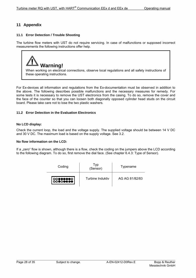
Check the current loop, the load and the voltage supply. The supplied voltage should be between 14 V DC and 30 V DC. The maximum load is based on the supply voltage. See 3.2. No flow information on the LCD: If a „zero“ flow is shown, although there is a flow, check the coding on the jumpers above the LCD according to the following diagram. To do so, first remove the dial face. (See chapter 6.4.3: Type of Sensor).
Coding Typ
(Sensor) Typename
Turbine Induktiv AG AG 81/82/83
Operating manual Turbine meter with UST, with HART® Communication EEx d and EEx de
Bopp & Reuther Messtechnik GmbH
A-EN-02412-D0Rev.E Subject to change. Page 29 of 35
Volume Meter cannot be reset to zero:
With the Reed "RESET" above the display, only the reset meter may be reset to zero, not the sum meter. The reset meter can only be reset, when this function is displayed. The display mode may be changed by means of the HART® protocol or with the Reed "DISPLAY" below the display. Touching time > 3 seconds.
Current output does not work properly:
If the value of the output current deviates from the theoretical reference value, the supply voltage and the maximum load limits must be checked. A load which is too large may result in a substantial decrease of the terminal voltage for the UST. The calibration of the 4 mA and the 20 mA points of the output characteristic curve must be checked, too. If the current output does not show analog values check the selection switch on the supply circuit board. (See also diagram in chapter 3.1.2)
Pulse output does not work properly:
IF the UST current pulse output is used, the double actuator must be set correctly (see diagram in chapter 3.1.2).
The current pulse is available at terminals 1 and 2, the NAMUR-pulse at terminals 3 and 4!
If the high level is lower than 20 mA check the supply voltage and the load (see chapter 3.2).
Pulse output when flow is zero:
If pulses are sent to the pulse output when there is no flow check pulse value, pulse relation factor and pulse width. If a large pulse width has been selected, the output of the pulses is processed rather slowly. If the factors have been selected in such a way that the theoretical output frequency is significantly higher than the maximum possible frequency, the excess pulses are stored. The overflow memory then sends signals with a maximum frequency even if the flow is zero until the memory is empty. Thus no volume pulses are lost.
Meter increments are too small:
Check volume unit KP-, KK- and pulse value factors as well as the decimal point.
Meter increments are too big:
Check volume unit KP-, KK- and pulse value factors as well as the decimal point.
Output current is over 20mA:
The flow of the turbine meter is larger than the end of the range of the measurement output. The range end must be increased accordingly.
Output current remains at 4mA for small flows:
The beginning of the range of the measurement output is set at a value that is too high. The beginning of the range must be reduced accordingly.

Turbine meter RQ with UST, with HART® Communication EEx d and EEx de Operating manual
Page 30 of 35 Subject to change. A-EN-02412-D0Rev.E Bopp & ReutherMesstechnik GmbH
Output current fluctuates significantly:
The revolutions of the turbine meter or the pulse frequency is very low. The minimum measurement range has not been reached. Attenuation of > 1s may result in a smoothing.
Values on the flow display are too high:
Check the flow unit and the KP- und KK-factors.
Values on the flow display are too small:
Check the flow unit and the KP- und KK-factors.
Data Transmission does not work properly:
The minimum load must be attained for reliable communication. The optimal minimum loop resistance is about 230 . If the load is higher a sufficiently high supply voltage must be available (see figures 1 and 2).
Data Transmission is not possible:
The UST must be connected with a point-to-point connection. Only one master may access the interface. The multi-drop address must be set to 0. Loop resistance and supply voltage must be within the limits given in figures 1 and 2. With these settings communication should be possible.
Operating manual Turbine meter with UST, with HART® Communication EEx d and EEx de
Bopp & Reuther Messtechnik GmbH
A-EN-02412-D0Rev.E Subject to change. Page 31 of 35
General information:
If the cause of a malfunction can not be detected, please contact the Bopp & Reuther Messtechnik service or send the device to Bopp & Reuther Messtechnik for repair
11.3 Rotation of the display
If you want to change the display direction, the LCD can be rotated 90° by our service personnel or by your-self. Remove the cover with the pane of glass and unscrew the fastening screws of the dial face. If you want to rotate the display 180° you only need to remove the electronics block and rotate it. If you want to rotate the display 90° you must remove the electronics block and the mounting plate below and rotate both. All assembly work may only performed off-circuit.

Turbine meter RQ with UST, with HART® Communication EEx d and EEx de Operating manual
Page 32 of 35 Subject to change. A-EN-02412-D0Rev.E Bopp & ReutherMesstechnik GmbH
11.4 Application examples
11.4.1 Application example 1
for application in non-hazardous areas for application in hazardous areas (EEx d)
Counter or flow computer
Local indicator
+
-24V
24V-
+
+
-24V
24V-
+
+
-
+
-
4
3
2
1
ground shield in cable gland
external ground terminal
+
-
+
-
4
3
2
1
+
-
+
-
4
3
2
1
+
-
+
-
4
3
2
1
00 0
00 0
00 0
Local indication without signal transmission
Pulses
4-20mA
Pulses
4-20mA
Pulses
4-20mA
Pulses
4-20mA
external ground terminal
ground shield in cable gland
external ground terminal
ground shield in cable gland
external ground terminal
ground shield in cable gland
Local indicator
Analog transmission 4-20mA to indicator or recorder
Analog transmission 1...5V to indicator or recorder
Pulse transmission 1/5V to counter or flow computer
Operating manual Turbine meter with UST, with HART® Communication EEx d and EEx de
Bopp & Reuther Messtechnik GmbH
A-EN-02412-D0Rev.E Subject to change. Page 33 of 35
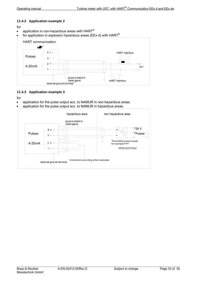
11.4.2 Application example 2
for application in non-hazardous areas with HART® for application in explosion hazardous areas (EEx d) with HART®
24V-
+
+
-
+
-
4
3
2
1
ground shield in cable gland
HART communication
Pulses
4-20mA
external ground terminal
HART interface
HART interface
11.4.3 Application example 3
for application for the pulse output acc. to NAMUR in non-hazardous areas application for the pulse output acc. to NAMUR in hazardous areas
hazardous area
for example P+F KFD2-ST-Ex2Transmitter power supply
Connection according other examples
non hazardous area
ground shield in cable gland
Pulses
4-20mA
external ground terminal
24 V
Pulses
KFD2-SOT2-Ex2
Turbine meter RQ with UST, with HART® Communication EEx d and EEx de Operating manual
Page 34 of 35 Subject to change. A-EN-02412-D0Rev.E Bopp & ReutherMesstechnik GmbH
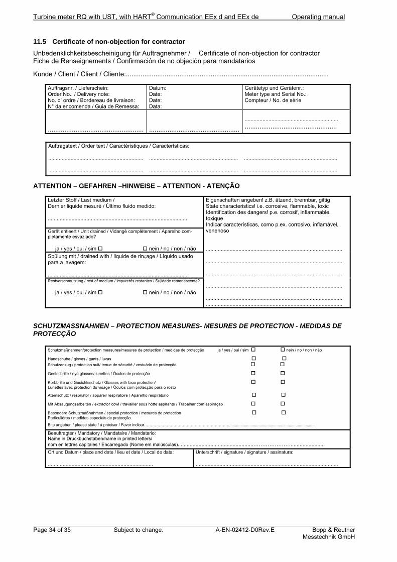
11.5 Certificate of non-objection for contractor
Unbedenklichkeitsbescheinigung für Auftragnehmer / Certificate of non-objection for contractor Fiche de Renseignements / Confirmación de no objeción para mandatarios
Kunde / Client / Client / Cliente:..............................................................................................................
Auftragsnr. / Lieferschein: Order No.: / Delivery note: No. d’ ordre / Bordereau de livraison: N° da encomenda / Guia de Remessa:
Datum: Date: Date: Data:
Gerätetyp und Gerätenr.: Meter type and Serial No.: Compteur / No. de série
....................................................
.................................................
............................................................... ..................................................
Auftragstext / Order text / Caractéristiques / Características: ................................................................ ............................................................ ............................................................... ................................................................ ............................................................ ...............................................................
ATTENTION – GEFAHREN –HINWEISE – ATTENTION - ATENÇÃO
Letzter Stoff / Last medium / Dernier liquide mesuré / Último fluido medido: ...............................................................................................
Eigenschaften angeben! z.B. ätzend, brennbar, giftig State characteristics! i.e. corrosive, flammable, toxic Identification des dangers! p.e. corrosif, inflammable, toxique Indicar características, como p.ex. corrosivo, inflamável, venenoso ............................................................................................ ............................................................................................ ............................................................................................ ............................................................................................ ............................................................................................ ............................................................................................
Gerät entleert / Unit drained / Vidangé complètement / Aparelho com-pletamente esvaziado? ja / yes / oui / sim nein / no / non / não
Spülung mit / drained with / liquide de rinage / Líquido usado para a lavagem: ............................................................................................... Restverschmutzung / rest of medium / impuretés restantes / Sujidade remanescente?
ja / yes / oui / sim nein / no / non / não
SCHUTZMASSNAHMEN – PROTECTION MEASURES- MESURES DE PROTECTION - MEDIDAS DE PROTECÇÃO
Schutzmaßnahmen/protection measures/mesures de protection / medidas de protecção ja / yes / oui / sim nein / no / non / não
Handschuhe / gloves / gants / luvas
Schutzanzug / protection suit/ tenue de sécurité / vestuário de protecção
Gestellbrille / eye glasses/ lunettes / Óculos de protecção
Korbbrille und Gesichtsschutz / Glasses with face protection/ Lunettes avec protection du visage / Óculos com protecção para o rosto
Atemschutz / respirator / appareil respiratoire / Aparelho respiratório
Mit Absaugungsarbeiten / extractor cowl / travailler sous hotte aspirante / Trabalhar com aspiração
Besondere Schutzmaßnahmen / special protection / mesures de protection Particulières / medidas especiais de protecção
Bite angeben / please state / à préciser / Favor indicar……………………………………………………….............................................................................
Beauftragter / Mandatory / Mandataire / Mandatario: Name in Druckbuchstaben/name in printed letters/ nom en lettres capitales / Encarregado (Nome em maiúsculas)...................................................………………….......................
Ort und Datum / place and date / lieu et date / Local de data: .......................................................................
Unterschrift / signature / signature / assinatura: ................................................................................................
Operating manual Turbine meter with UST, with HART® Communication EEx d and EEx de
Bopp & Reuther Messtechnik GmbH
A-EN-02412-D0Rev.E Subject to change. Page 35 of 35
11.6 EC-Type Approval Certificate 94/9/EG USTD / USTE (May 2000)
11.7 EC-Type Approval Certificate 97/23/EG series RQ (July 2005)
11.8 EC-Conformity declaration (September 2013)