tuning the capacitive touch solution - application project · ae-cap1-mc board, choose the mutual...
TRANSCRIPT

Application Note
R20AN0448EU0106 Rev.1.06 Page 1 of 32 Oct 11, 2018
Renesas Synergy™ Platform
Tuning the Capacitive Touch Solution Introduction You will need to perform a Capacitive Touch Tuning Process before using the Capacitive Touch Framework used to perform the touch detection in the Synergy Software™ Package (SSP). The tuning process uses the Capacitive Touch Sensing Unit (CTSU) HAL driver provided by the SSP.
This document enables you to effectively use the Capacitive Touch Tuning Process in your own design by referencing several sample capacitive touch tuning projects for Renesas Synergy™ Kits. On completion of this guide, you will be able to create capacitive touch tuning project for your own hardware system, configure it correctly for the target application, and use the attached tuning example code in your tuning project.
The tuning process generates a set of configuration settings for the CTSU on the Synergy MCU. These configurations include touch detection threshold and hysteresis at an optimized CTSU hardware configuration to achieve optimal sensitivity for the hardware platform tuned. For details on Capacitive Touch Sensing Unit (CTSU) and its principles of operation, see the applicable Renesas Synergy Microcontroller User’s Manual.
Required Resources To build and run the capacitive touch tuning example, you need:
• Renesas AE-CAP1, DK-S124, SK-S7G2 or PK-S5D9 Kit You only need to have the kit intended to perform the tuning on.
• Renesas Synergy e2 studio ISDE v6.2.1 or later, or IAR Embedded Workbench® for Renesas Synergy™ v8.23.1 or later
• Synergy Software Package (SSP) 1.5.0 or later • Synergy Standalone Configuration (SSC) 6.2.1 and later • SEGGER J-Link® USB driver • Two Micro USB cables • Serial to USB conversion cable • Capacitive Touch Workbench for Synergy (CTW for Synergy) First Step Guide version 1.5.0.0000.028 or later • Download all the required Renesas software from the Renesas Synergy Gallery;
(https://synergygallery.renesas.com).
Prerequisites and Intended Audience This application project assumes you have some experience with the Renesas Synergy e2 studio ISDE and Synergy Software Package (SSP). Before you perform the procedure in this application note, follow the procedure in the SSP User’s Manual to build and run the Blinky project. Doing so enables you to become familiar with the e2 studio and the SSP, and to ensure that the debug connection to your board functions properly. In addition, this application project assumes you have some knowledge on Capacitive Touch Technology and the Capacitive Touch Hardware Design and Layout Guide for Renesas Synergy. The intended audience are users who want to develop Capacitive Touch applications with CTSU using Synergy S1/S3/S5/S7 MCU Series.
R20AN0448EU0106 Rev.1.06
Oct 11, 2018

Renesas Synergy™ Platform Tuning the Capacitive Touch Solution
R20AN0448EU0106 Rev.1.06 Page 2 of 32 Oct 11, 2018
Contents
1. Capacitive Touch Tuning Overview ........................................................................................... 3 1.1 Capacitive Touch Workbench for Renesas Synergy............................................................................... 3 1.2 Capacitive Touch Tuning support from SSP ........................................................................................... 3 1.2.1 SSP CTSU Tuning Driver ...................................................................................................................... 3 1.2.2 SSP CTSU HAL Driver .......................................................................................................................... 4 1.2.3 USB and UART communication with CTW for Synergy ........................................................................ 5 1.2.4 Operational Notes and Limitations of current Capacitive Touch Tuning solution ................................. 6
2. Capacitive Touch Tuning Operating Overview .......................................................................... 7
3. Capacitive Touch Tuning with CTW for Synergy ....................................................................... 9 3.1 Example capacitive touch tuning software projects ................................................................................ 9 3.1.1 Importing the CTSU Tuning Project ...................................................................................................... 9 3.1.2 Configurations of the Capacitive Touch Tuning Project ...................................................................... 10 3.2 Start the CTW for Synergy .................................................................................................................... 11 3.3 Running the CTSU Tuning Project ........................................................................................................ 16 3.3.1 Powering up the AE-CAP1-S1 and AE-CAP1-BWS board ................................................................. 16 3.3.2 Install USB CDC Driver on Windows .................................................................................................. 17 3.4 Continue and finish tuning with CTW for Synergy ................................................................................. 18 3.5 Monitoring the CTSU operation after tuning .......................................................................................... 24
4. Using the Tuning Results in Capacitive Touch Applications ................................................... 24 4.1 Sample capacitive touch applications ................................................................................................... 24 4.2 General steps to import the tuning result to an application project ....................................................... 25
5. Sensor Layout Summary ......................................................................................................... 25 5.1 Capacitive Touch Sensor layout on AE-CAP1 ...................................................................................... 25 5.1.1 AE-CAP1-S1 and AE-CAP1-BWS Touch Sensor layout .................................................................... 25 5.1.2 AE-CAP1-S3 and AE-CAP1-BWS Touch Sensor layout .................................................................... 26 5.1.3 AE-CAP1-S1 and AE-CAP1-SC Touch Sensor layout ....................................................................... 26 5.1.4 AE-CAP1-S3 and AE-CAP1-SC Touch Sensor layout ....................................................................... 26 5.1.5 AE-CAP1-S1 and AE-CAP1-MC ......................................................................................................... 27 5.1.6 AE-CAP1-S3A7 and AE-CAP1-MC ..................................................................................................... 27 5.2 Capacitive Touch Sensor layout on SK-S7G2 (v3.2 and later) ............................................................. 28 5.3 Capacitive Touch Sensor layout on DK-S124 ....................................................................................... 29 5.4 Capacitive Touch Sensor layout on PK-S5D9 ...................................................................................... 29
6. Creating a Capacitive Touch Tuning Project for a Custom PCB board ................................... 29
7. References .............................................................................................................................. 30
Revision History .............................................................................................................................. 32

Renesas Synergy™ Platform Tuning the Capacitive Touch Solution
R20AN0448EU0106 Rev.1.06 Page 3 of 32 Oct 11, 2018
1. Capacitive Touch Tuning Overview Touch pad capacitive values change based on the board layout and environmental conditions. This Tuning process optimizes product performance by measuring touch pad capacitive values in the touched and untouched state. The tuning process helps the capacitive touch system designer optimize touch pad operations.
The capacitive touch tuning process uses several pieces of software together with the hardware system to perform the tuning. To establish a functioning capacitive touch system, three software components are needed:
1. The Capacitive Touch Tuning Software Project 2. The Capacitive Touch Workbench (CTW) for Synergy 3. This Application Software Project This application project focuses on the capacitive touch tuning operation. You are advised to reference the Self-Capacitive Touch Software Application Design with S124 and S3A7 Synergy MCUs and the Mutual-Capacitive Touch Software Application Design with S124 and S3A7 Synergy MCUs to understand more details on how the application makes sure of the capacitive touch tuning result.
The following sections will introduce the PC side of the Capacitive Touch Tuning Software and the Synergy Tuning Software Projects that are used in conjunction with the PC side tools.
1.1 Capacitive Touch Workbench for Renesas Synergy The Capacitive Touch Workbench for Renesas Synergy (CTW for Synergy) is a GUI that runs on Windows and communicates with the target touch system via a USB or UART connection.
• The GUI is a modified version of the original Workbench 6 and supports only Synergy products. • You will perform the tuning processes using the GUI and create a layout of the target board including buttons,
sliders and wheels that specify which Capacitive Touch Sensing Unit (CTSU) channels are used for each widget. • The application then runs the tuning process and prompts you at appropriate points to touch and release each widget
to determine the thresholds. • You can monitor the CTSU values on the target board using the GUI once tuning is complete. Visit http://www.renesassynergy.com/gallery to download the latest CTW for Synergy before proceeding to any Capacitive Touch Tuning exercises. Refer to the Capacitive Touch Workbench User’s Manual for Renesas Synergy for more understanding on this PC side software tool.
1.2 Capacitive Touch Tuning support from SSP The target system needs to run the Synergy CTSU Tuning project in conjunction with the CTW for Synergy to perform capacitive touch tuning. In addition to the capacitive touch tuning and CTSU driver, the communications framework on USB and UART are used in the tuning project to communicate with the CTW for Synergy. The following sections describe the SSP components used in the capacitive touch tuning projects.
1.2.1 SSP CTSU Tuning Driver This is a capacitive touch tuning driver in the SSP. To create a tuning project from scratch, start by creating a new thread and bring in the CTSU Tuning driver as shown in the following figure.

Renesas Synergy™ Platform Tuning the Capacitive Touch Solution
R20AN0448EU0106 Rev.1.06 Page 4 of 32 Oct 11, 2018
Bring in the SSP CTSU tuning block as shown in the following figure.
Figure 1 Including the CTSU Tuning Driver The SSP CTSU tuning driver has three properties to configure.
• Two of the properties are not implemented with the current CTSU tuning driver: Tuning a board with Buttons and tuning a board with a Slider or Wheel. These two properties (Slider or Wheel) are not used in the tuning process and are placeholders for future development.
• You need to select the capacitance mode by setting the Self or Mutual Capacitance Mode property. For the AE-CAP1-BWS button wheels slider board, you will use the Self-Capacitance Mode. To work with the AE-CAP1-MC board, choose the Mutual Capacitance Mode.
Figure 2 Configuring the tuning driver With the current SSP CTSU support, this tuning driver is very simple and utilizes the lower layer CTSU HAL driver to perform the tuning process that is described in the next section.
1.2.2 SSP CTSU HAL Driver The CTSU Driver is used to initialize the CTSU peripheral to detect a change in capacitance on any of the configured (and enabled) channels, perform requisite filtering and generate a variety of data that can be used by higher level widget layers like buttons wheel and sliders. The tuning project utilizes this CTSU HAL driver to come up with the optimal CTSU setting with the help from the tuning algorithms from CTW for Synergy.
The capacitive touch tuning driver automatically adds the SSP CTSU HAL Driver to the Synergy configurator. The following figure is an example configuration for tuning the AE-CAP1 Button Wheel Slider application board with the AE-CAP-S1 target board.
Renesas Synergy™ Platform Tuning the Capacitive Touch Solution
R20AN0448EU0106 Rev.1.06 Page 5 of 32 Oct 11, 2018
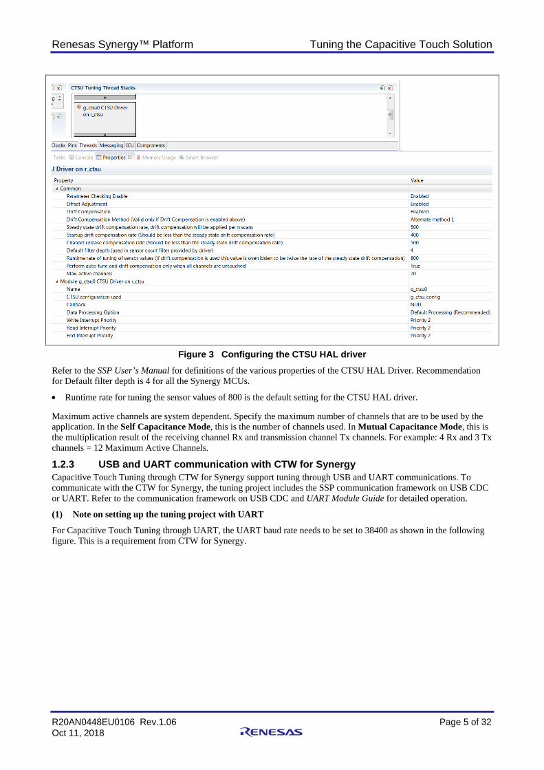
Figure 3 Configuring the CTSU HAL driver Refer to the SSP User’s Manual for definitions of the various properties of the CTSU HAL Driver. Recommendation for Default filter depth is 4 for all the Synergy MCUs.
• Runtime rate for tuning the sensor values of 800 is the default setting for the CTSU HAL driver. Maximum active channels are system dependent. Specify the maximum number of channels that are to be used by the application. In the Self Capacitance Mode, this is the number of channels used. In Mutual Capacitance Mode, this is the multiplication result of the receiving channel Rx and transmission channel Tx channels. For example: 4 Rx and 3 Tx channels = 12 Maximum Active Channels.
1.2.3 USB and UART communication with CTW for Synergy Capacitive Touch Tuning through CTW for Synergy support tuning through USB and UART communications. To communicate with the CTW for Synergy, the tuning project includes the SSP communication framework on USB CDC or UART. Refer to the communication framework on USB CDC and UART Module Guide for detailed operation.
(1) Note on setting up the tuning project with UART
For Capacitive Touch Tuning through UART, the UART baud rate needs to be set to 38400 as shown in the following figure. This is a requirement from CTW for Synergy.

Renesas Synergy™ Platform Tuning the Capacitive Touch Solution
R20AN0448EU0106 Rev.1.06 Page 6 of 32 Oct 11, 2018
Figure 4 UART configuration for tuning
1.2.4 Operational Notes and Limitations of current Capacitive Touch Tuning solution (1) Working with Custom Capacitive Touch PCB Board
The custom BSP will need to be created first to set all the intended CTSU touch sensing pins. When the custom BSP is selected in the BSP tab, all the CTSU touch sensing pins will be automatically selected. You can select any number of the enabled capacitive touch pins during the debugging stage of the tuning project. (2) Limitation on PCLKB selection in the Capacitive Touch Application
The current version of the CTW for Synergy has limitations on the PCLKB frequency setting in capacitive touch tuning and application. Only PCLKB settings 24 MHz or 32 MHz are supported.
In addition, capacitive touch tuning uses USB to communicate with the CTW for Synergy. Communication through USB imposes additional system clock setting requirement.
These limitations (Capacitive Touch Tuning and USB usage) have implications on the maximum CPU frequencies that can be run with capacitive touch applications. See the following table for details.

Renesas Synergy™ Platform Tuning the Capacitive Touch Solution
R20AN0448EU0106 Rev.1.06 Page 7 of 32 Oct 11, 2018
Table 1 CPU Clock
Synergy MCU Max CPU clock CPU clock with tuning project S124 32 MHz 24 MHz S3A7 48 MHz 48 MHz S5D9 120 MHz 96 MHz S7G2 240 MHz 192 MHz
(3) Limitations on the UART baud rate during tuning with CTW for Synergy
Current version CTW for Synergy only supports tuning through the UART port on the target board at baud rate 38400. Refer to Figure 4 for more information on the UART configuration for tuning with CTW for Synergy.
(4) Limitations on monitoring after tuning
The slider window and wheel window are not active when activating the monitor window after tuning before system is power recycled. See section 3.5 to understand monitoring after tuning.
(5) Monitoring result using unfiltered data
This version of the CTSU driver does not allow filtered data to send to the CTW for Synergy for monitoring. Raw data is sent to CTW for Synergy for monitoring. As a result, noise is observed than compared with using the filtered data in monitoring functionality.
2. Capacitive Touch Tuning Operating Overview The following figure shows the high-level flowchart that explains the high-level operation sequence of a Capacitive Touch System in terms of interacting with the various software components in the capacitive touch solution.
• From a high level You first use the capacitive touch tuning software project and the CTW for Synergy to generate the capacitive
touch CTSU configurations together with the touch thresholds and hysteresis. Next, you copy the tuning result to the application project to perform touch detection using the SSP Capacitive
Touch Framework. This application project focuses on the operation related with the CTW for Synergy using the Capacitive Touch Tuning Software Projects. The operation with the application are described in other application projects. You can reference Section 3.1 for the related touch detection application projects.

Renesas Synergy™ Platform Tuning the Capacitive Touch Solution
R20AN0448EU0106 Rev.1.06 Page 8 of 32 Oct 11, 2018
Figure 5 Capacitive Touch Operational flow chart

Renesas Synergy™ Platform Tuning the Capacitive Touch Solution
R20AN0448EU0106 Rev.1.06 Page 9 of 32 Oct 11, 2018
3. Capacitive Touch Tuning with CTW for Synergy 3.1 Example capacitive touch tuning software projects There are several references of Capacitive Touch Tuning Software Projects included in this application project.
• Sample tuning projects for AE-CAP1, SK-S7G2 (v3.2 or later), DK-S124 and PK-S5D9 are provided to use with CTW for Synergy. These sample projects can be used as reference projects when starting to create the Capacitive Touch Tuning Application Project for your own board.
Capacitive_Touch_Tuning_Projects_AE_CAP1.zip
Capacitive_Touch_Tuning_Projects_SK_S7G2.zip
Capacitive_Touch_Tuning_Projects_DK_S124.zip
Capacitive_Touch_Tuning_Projects_PK_S5D9.zip
Below is a list of Capacitive Touch Tuning Projects included inside these zip files.
Table 2 Capacitive Touch Tuning Projects included in this application project
Tuning Software Projects Project Description Tuning_AE_CAP_S124_BWS • Tuning Project for system with AE-CAP1-S124 connected
with AE-CAP1-BWS board via USB Tuning_AE_CAP_S124_BWS_UART • Tuning Project for system with AE-CAP1-S124 connected
with AE-CAP1-BWS board via UART Tuning_AE_CAP_S124_MT • Tuning Project for system with AE-CAP1-S124 connected
with AE-CAP1-MC board via USB Tuning_AE_CAP_S124_MT_UART • Tuning Project for system with AE-CAP1-S124 connected
with AE-CAP1-MC board via UART Tuning_AE_CAP_S124_ST • Tuning Project for system with AE-CAP1-S124 connected
with AE-CAP1-SC board via USB Tuning_AE_CAP_S124_ST_UART • Tuning Project for system with AE-CAP1-S124 connected
with AE-CAP1-SC board via UART Tuning_AE_CAP_S3A7_BWS • Tuning Project for system with AE-CAP1-S3A7 connected
with AE-CAP1-BWS board Tuning_AE_CAP_S3A7_MT • Tuning Project for system with AE-CAP1-S3A7 connected
with AE-CAP1-MC board Tuning_AE_CAP_S3A7_ST • Tuning Project for system with AE-CAP1-S3A7 connected
with AE-CAP1-SC board Tuning_DK_S124 • Tuning Project for DK-S124 Tuning_SK_S7G2 • Tuning Project for SK-S7G2 (Version 3.2 and later) Tuning_PK_S5D9 • Tuning Project for PK_S5D9
3.1.1 Importing the CTSU Tuning Project The general tuning procedure is common to all hardware kits. This Application Note will use the Capacitive Touch System composed of the AE-CAP1-S1 and AE-CAP1-BWS board as an example to explain the general procedure. You can reference this procedure and the sensor layout information in Section 5 to perform Capacitive Touch Tuning for other kits.
• Refer to the Synergy Project Import Guide (11an0023eu0120-synergy-ssp-import-guide.pdf , included in this package) for instructions on importing the projects into e2 studio or IAR Embedded Workbench and building/running the application.
• The included Capacitive_Touch_Tuning_Projects_AE_CAP1.zip file contains several tuning projects. We will use Tuning_AE_CAP1_S124_BWS as an example in the description of the tuning steps. When working with all tuning projects, you need to follow the same steps.
• To work with the AE-CAP1 Sample Projects in e2 studio ISDE, the AE-CAP1 BSP files: Renesas.Synergy_Board_s124_ae_cap1.1.4.0.pack and Renesas.Synergy_board_s3a7_ae_cap1.1.4.0.pack (for 1.4.0 pack) or Renesas.Synergy_Board_s124_ae_cap1.1.5.0.pack and

Renesas Synergy™ Platform Tuning the Capacitive Touch Solution
R20AN0448EU0106 Rev.1.06 Page 10 of 32 Oct 11, 2018
Renesas.Synergy_board_s3a7_ae_cap1.1.5.0.pack (for 1.5.0 pack) need to be placed in the your e2 studio installation folder \\<your e2_studio folder<\internal\projectgen\arm\Packs.
• To work with the AE-CAP1 Sample Projects in IAR Embedded Workbench, the AE-CAP1 BSP files need to be placed in your IAR EW for Synergy SCC folder; \<your SSC folder>\internal\projectgen\arm\Packs.
• Import Tuning_AE_CAP1_S124_BWS (for USB connection) or Tuning_AE_CAP1_S124_BWS_UART (for UART connection) and set up the license file. Review the tuning project settings below before proceeding to the tuning steps.
3.1.2 Configurations of the Capacitive Touch Tuning Project Reviewing the Synergy configuration of the Tuning_AE_CAP1_S124_BWS helps us understanding the various configuration properties that a capacitive touch tuning project needs to setup. In case of error in your tuning process, these are some of the aspects you need to take care of from the software side.
1. Open the Synergy Configuration view. 2. You can do this by double-clicking the configuration.xml file in the Project Explorer pane and changing the
perspective to Synergy Configuration. In the Synergy Configuration view, select the Pins tab and expand the peripherals entry to select CTSU. Observe the CTSU pins that are used for Capacitive Touch in your project. You will notice that all below 28 capacitive touch pins that are assigned as capacitive touch sensing pins on the AE-CAP1-S1 board are enabled. Reference the hardware schematic to understand the hardware pins used in the AE-CAP1-BWS board. Although the AE-CAP1-BWS board only uses 20 out of the 28 capacitive touch pins, it is ok to have all the touch sensing pins enabled in the tuning project. The tuning layout determines the group of pins that will be tuned.
Table 3 Hardware configuration with AE-CAP1-S1 and AE-CAP1-BWS
S124 Pin name Function TSCAP CTSU power stabilization TS00-TS02, TS04-TS09, TS12-TS28, TS30-TS31 Capacitive touch sensing TS03, TS10, TS11 are assigned other functionalities. See schematic TS29 not functioning See hardware user manual
1. Select the Clocks tab to observe the clocks, including the PCLKB, to be identical to the eventual user application
project where the results of this tuning procedure are used. For the Tuning_AE_CAP1_S124 _BWS tuning project, the PCLKB is set to 24 MHz.
2. In the Synergy Configuration view, select the Threads tab.
3. Then select the CTSU Tuning Thread.
4. On the right, under CTSU Tuning Thread Stacks, select g_ctsu CTSU driver on r_ctsu. Confirm the CTSU driver has the same configuration as in Figure 3.
5. In the Properties window, observe the Maximum Active Channels is set to 20.
Note: In Self-Capacitance Mode, the Maximum Active Channels is the number of channels used. In Mutual-Capacitance Mode, this value is the maximum number of channel combinations. For example, in Mutual-Capacitance Mode there are three (3) receive channels and four (4) transmit channels, and the Maximum Active Channels entry would be 12.
6. Under the CTSU Tuning Thread Stacks, select CTSU Tuning on r_ctsu.
In the Properties window, confirm that Self-Capacitance Mode is selected for the AE-CAP1-BWS board tuning. Leave the other, see Figure 2.

Renesas Synergy™ Platform Tuning the Capacitive Touch Solution
R20AN0448EU0106 Rev.1.06 Page 11 of 32 Oct 11, 2018
3.2 Start the CTW for Synergy 1. Open the CTW for Synergy. Click START like in Figure 6.
Figure 6 Start FIRST STEP GUIDE 2. Click Next shown in the following figure.
Figure 7 Major steps in tuning with CTW for Synergy
Renesas Synergy™ Platform Tuning the Capacitive Touch Solution
R20AN0448EU0106 Rev.1.06 Page 12 of 32 Oct 11, 2018
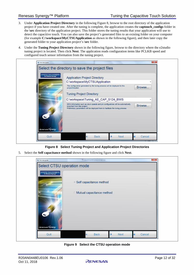
3. Under Application Project Directory in the following Figure 8, browse to the root directory of the application project if you have created one. After the tuning is complete, the application creates the captouch_configs folder in the \src directory of the application project. This folder stores the tuning results that your application will use to detect the capacitive touch. You can also save the project’s generated files to an existing folder on your computer (for example C:\workspace\MyCTSUApplication as shown in the following figure), and then later copy the generated folder to your application project’s \src folder.
4. Under the Tuning Project Directory shown in the following figure, browse to the directory where the e2studio tuning project is located. Then click Next. The application reads configuration items like PCLKB speed and configured touch sensor information from the tuning project.
Figure 8 Select Tuning Project and Application Project Directories 5. Select the Self capacitance method shown in the following figure and click Next.
Figure 9 Select the CTSU operation mode

Renesas Synergy™ Platform Tuning the Capacitive Touch Solution
R20AN0448EU0106 Rev.1.06 Page 13 of 32 Oct 11, 2018
This capacitance method selected here should match the configuration in Section 3.1.2 step 8.
6. Create the layout for your board by using the widgets on the right-hand pane in the following figure. You can add buttons, sliders and wheels using this pane as illustrated.
• To specify the CTSU channels used by each button, right-click the widget and select Channel as shown in the following figure. Follow the same procedure to create all three buttons.
Figure 10 Add Button to the layout Note: In Self-Capacitance mode, only a single channel needs to be specified. In Mutual-Capacitance mode, specify
both transmit and receive channels.
Note: There is a Save Layout button on the right corner of this window. Once all the touch sensors are assigned, you can save this layout for future tuning sessions. Reference the CTW for Synergy User’s Manual to understand the usage of the Save Layout button.
• To configure the slider and wheel, right-click on the object. Select Setup. Change the number of channels used on your board to specify the channels used as shown in the following.
Right click on the button

Renesas Synergy™ Platform Tuning the Capacitive Touch Solution
R20AN0448EU0106 Rev.1.06 Page 14 of 32 Oct 11, 2018
Figure 11 Add Wheel and Slider to the layout Note: When configuring the slider and wheel on the AE-CAP1-BWS board, the sequence of channels assigned must
match the hardware layout of the board.
To get the slider channel order displayed, channels were added in the order TS05, TS04, TS01, TS00, and TS02. To get the 4-sensor wheel (Wheel0) channel order displayed, channels were added in the order TS24, TS20,
TS27, and TS30 clockwise. To get the 8-sensor wheel (Wheel1) channel order displayed, channels were added in the order TS22, TS19,
TS18, TS17, TS8, TS28, TS31, and TS25 clockwise. To change the slider and wheel orientation, right-click the widget to change the orientation.
• In case of the slider, the arrows point to the channel that generates the highest coordinate values in the callback during its operation. Only Self-Capacitance mode is currently supported for sliders and wheels.
• The following figure is the finished AE-CAP1-BWS board layout when controlled by AE-CAP1-S1 MCU board. Click Next.
Change to 8 for the second wheel

Renesas Synergy™ Platform Tuning the Capacitive Touch Solution
R20AN0448EU0106 Rev.1.06 Page 15 of 32 Oct 11, 2018
Figure 12 AE-CAP1-BWS tuning layout 7. The following figure shows the default aggregate resistance values for each configured channel. The default values
are recommended for all designs. The value should be adjusted by you depending on noise environment of the application.
Figure 13 Select resistance from the electrode to TSn pin 8. When you reach the following screen, the application has internally generated the placeholder arrays and other
structures required for this configuration. Do not click Next. Follow Section 3.3.1 to connect your PC to target the MCU via USB. Step 1 in Section 3.4 will instruct you to come back to this screen to continue the tuning process.

Renesas Synergy™ Platform Tuning the Capacitive Touch Solution
R20AN0448EU0106 Rev.1.06 Page 16 of 32 Oct 11, 2018
Figure 14 Target board startup
3.3 Running the CTSU Tuning Project 3.3.1 Powering up the AE-CAP1-S1 and AE-CAP1-BWS board At this point, we need to run the CTSU tuning project. First set up the AE-CAP1-S1 and AE-CAP1-BWS boards:
• Set J2 on AE-CAP1-S1 to 5V USB. • Connect the AE-CAP1-S1 and AE-CAP1-BWS board together. • Connect J8 and J10 on the AE-CAP1-S1 board to the PC through USB cables. • Ensure that J4 on AE-CAP1-S1 board is open. Special Notes on connecting the UART tuning with AE-CAP1-S124:
• To use the UART tuning program, Tuning_AE_CAP1_S124_BWS_UART, you need to solder a pin header on J9 and connect a USB to Serial cable as shown in the following figure.
Figure 15 Hardware setup for AE-CAP1-S1 and AE-CAP1-BWS Following are the details on the UART pin connection. Remove jumpers from J5 (leave J5 open). The UART pins are shared with the panel board I2C led control pins. This hardware setup is also required for tuning AE-CAP1 kit with AE-CAP1-S124 and AE-CAP1-MC or AE-CAP1-SC systems.
Renesas Synergy™ Platform Tuning the Capacitive Touch Solution
R20AN0448EU0106 Rev.1.06 Page 17 of 32 Oct 11, 2018
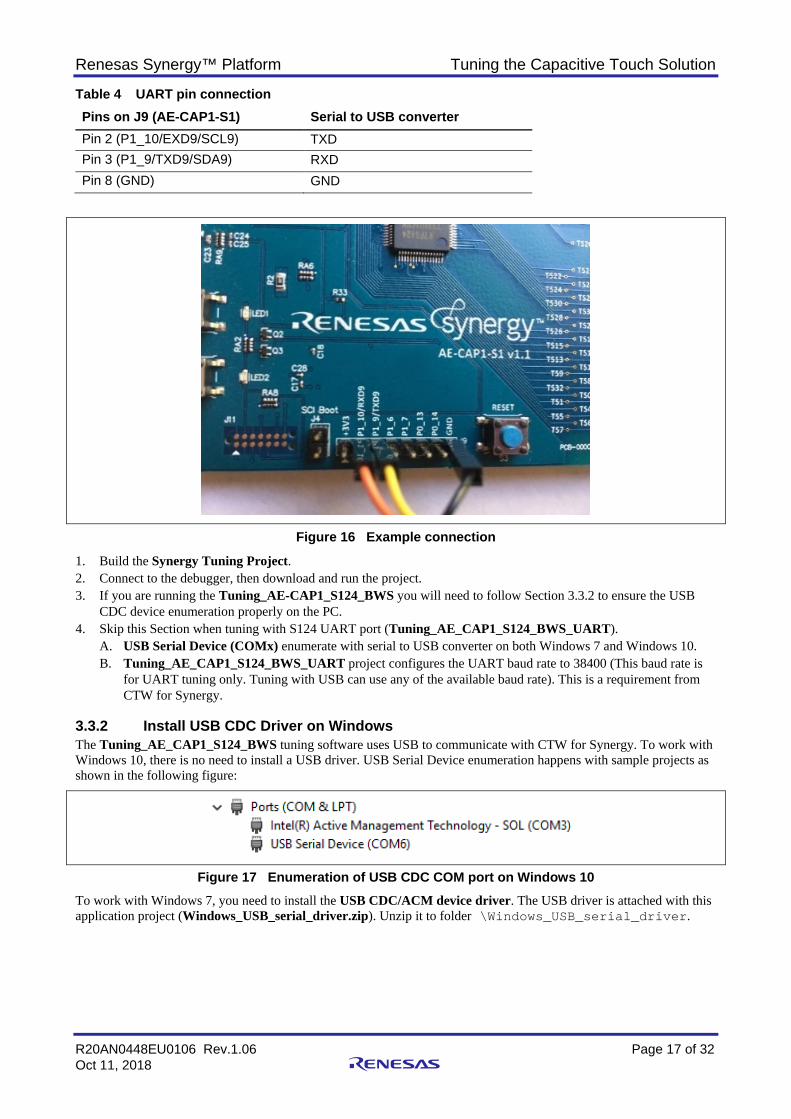
Table 4 UART pin connection
Figure 16 Example connection 1. Build the Synergy Tuning Project. 2. Connect to the debugger, then download and run the project. 3. If you are running the Tuning_AE-CAP1_S124_BWS you will need to follow Section 3.3.2 to ensure the USB
CDC device enumeration properly on the PC. 4. Skip this Section when tuning with S124 UART port (Tuning_AE_CAP1_S124_BWS_UART).
A. USB Serial Device (COMx) enumerate with serial to USB converter on both Windows 7 and Windows 10. B. Tuning_AE_CAP1_S124_BWS_UART project configures the UART baud rate to 38400 (This baud rate is
for UART tuning only. Tuning with USB can use any of the available baud rate). This is a requirement from CTW for Synergy.
3.3.2 Install USB CDC Driver on Windows The Tuning_AE_CAP1_S124_BWS tuning software uses USB to communicate with CTW for Synergy. To work with Windows 10, there is no need to install a USB driver. USB Serial Device enumeration happens with sample projects as shown in the following figure:
Figure 17 Enumeration of USB CDC COM port on Windows 10 To work with Windows 7, you need to install the USB CDC/ACM device driver. The USB driver is attached with this application project (Windows_USB_serial_driver.zip). Unzip it to folder \Windows_USB_serial_driver.
Pins on J9 (AE-CAP1-S1) Serial to USB converter Pin 2 (P1_10/EXD9/SCL9) TXD Pin 3 (P1_9/TXD9/SDA9) RXD Pin 8 (GND) GND
Renesas Synergy™ Platform Tuning the Capacitive Touch Solution
R20AN0448EU0106 Rev.1.06 Page 18 of 32 Oct 11, 2018
1. Upon download and running the application, the CDC/ACM device shows up in the Device Manager of your PC under the Universal Serial Bus Controller group as UNKNOWN DEVICE.
2. Right click on this device and select Update Driver Software. 3. When prompted for the location of the drivers, browse to the location \Windows_USB_serial_driver you
created previously. 4. Once the driver is updated a new COM device shows up in the Device Manager as shown in the following figure.
Figure 18 Enumeration of USB CDC COM port on Windows 7
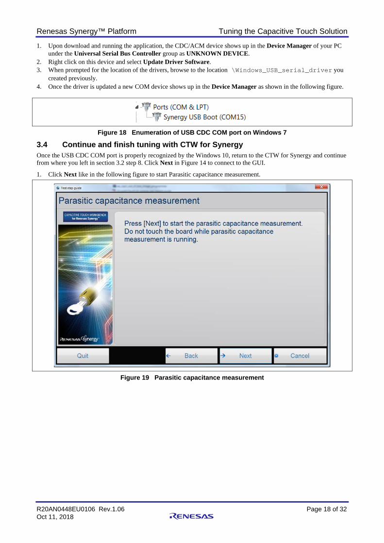
3.4 Continue and finish tuning with CTW for Synergy Once the USB CDC COM port is properly recognized by the Windows 10, return to the CTW for Synergy and continue from where you left in section 3.2 step 8. Click Next in Figure 14 to connect to the GUI.
1. Click Next like in the following figure to start Parasitic capacitance measurement.
Figure 19 Parasitic capacitance measurement

Renesas Synergy™ Platform Tuning the Capacitive Touch Solution
R20AN0448EU0106 Rev.1.06 Page 19 of 32 Oct 11, 2018
This step does not require your intervention. Do not touch the sensors during this process.
Figure 20 Result of parasitic capacitance measurement 1. Click Next shown in Figure 20 to start Offset current tuning. 2. This step does not require your intervention and takes a few minutes to complete, depending on the number of
channels being tuned. Do not touch the sensors during this process.
Figure 21 Offset current tuning The Offset tuning results show the chosen drive frequency for each channel.
Renesas Synergy™ Platform Tuning the Capacitive Touch Solution
R20AN0448EU0106 Rev.1.06 Page 20 of 32 Oct 11, 2018
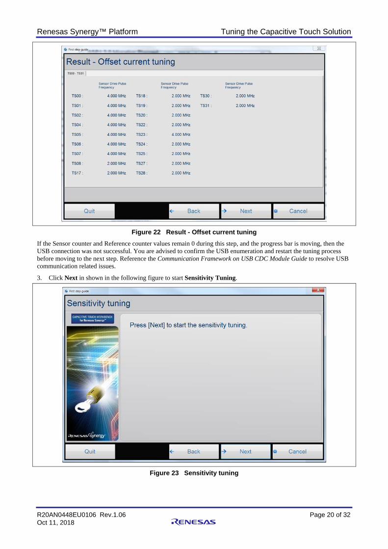
Figure 22 Result - Offset current tuning If the Sensor counter and Reference counter values remain 0 during this step, and the progress bar is moving, then the USB connection was not successful. You are advised to confirm the USB enumeration and restart the tuning process before moving to the next step. Reference the Communication Framework on USB CDC Module Guide to resolve USB communication related issues.
3. Click Next in shown in the following figure to start Sensitivity Tuning.
Figure 23 Sensitivity tuning

Renesas Synergy™ Platform Tuning the Capacitive Touch Solution
R20AN0448EU0106 Rev.1.06 Page 21 of 32 Oct 11, 2018
4. The following steps require your intervention. See Section 4.1.1 to match the button TS numbers to the buttons on AE-CAP1-BWS. For button sensitivity tuning shown in the following figure, the following actions are required. A. When prompted, apply maximal touch. This entails covering the entire sensor pad to the specified sensor.
Press Y on the PC while touching the button. B. Apply normal touch three (3) times. This means covering the sensor by 70% to 80% of the sensor area. Press
Y on the PC each time while touching the button. Depending on the noise level in the application environment, the definition of normal press may differ in your application. This way will be the expected pressing for the sensor touch detection in a real application.
Figure 24 Sensitivity tuning for buttons Repeat the Sensitivity tuning process for all the buttons. The sensor count should increase with self-capacitive buttons upon pressing, compared with the released state. Note that for mutual capacitive touch buttons, the sensor count should decrease with mutual-capacitive touch button upon pressing compared with released state.

Renesas Synergy™ Platform Tuning the Capacitive Touch Solution
R20AN0448EU0106 Rev.1.06 Page 22 of 32 Oct 11, 2018
5. The slider and wheel Sensitivity Tuning instructions require you to slide a finger over the slider/wheel a few times when prompted by the GUI as shown in the following figure. You do not need to hold the touch when pressing the Y key for slider and wheel sensitivity tuning.
Figure 25 Sensitivity tuning for slider and wheels Once the tuning process completes, a graphical display for each channel shows the capacitances in the touched and untouched state. The display also shows the threshold that a touch is detected. These thresholds can be manually edited later if the thresholds are not satisfactory. This can happen for example, you might want a tighter threshold

Renesas Synergy™ Platform Tuning the Capacitive Touch Solution
R20AN0448EU0106 Rev.1.06 Page 23 of 32 Oct 11, 2018
knowing there are quite some RF noise in the application environment. In this case, you will want to increase the threshold to avoid noises being identified as touch.
Figure 26 Result of sensitivity tuning for buttons For slider tuning results, no data is shown for the individual sensor element.
6. To view the slider tuning results, change the pull-down option from Sensor Counter Value to Slider/Wheel threshold to view the generated threshold values as shown in the following figure. You can redo the Sensitivity Tuning for selected channels using the Retry option on the same screen. This could happen for example if you think certain channel’s threshold is too low or too high based on your experience.
Figure 27 Result of sensitivity tuning for slider/wheel threshold

Renesas Synergy™ Platform Tuning the Capacitive Touch Solution
R20AN0448EU0106 Rev.1.06 Page 24 of 32 Oct 11, 2018
7. The application generates the captouch_configs folder with the tuned configuration for all the widgets selected and copies them to the application directory that was initially specified.
8. Click Next, then click Finish to complete Sensitivity Tuning. The generated tuning files can now be used in the application project.
3.5 Monitoring the CTSU operation after tuning Once the basic tuning is complete, and before stopping the debugger, it is possible in the GUI to view the sensor count values for each sensor, in both the touched and untouched states.
1. Click Connection and choose Serial Port Connection. • For tuning through UART on Windows 7 and Windows 10, the UART baud rate in the tuning software project
needs to use 38400. The CTW for Synergy automatically connects with the USB Serial Device COM port without.
• For tuning through USB on Windows 7 and Windows 10, the system supports all the available baud rate settings.
2. The connection is established when the status changes to Connected at the bottom left. 3. Once the status changes, select Capacitive Touch > Start Monitor to begin monitoring CTSU data. 4. Click Capacitive Touch > Status Monitor to bring up each configured sensor channel one-at-a-time. You can also
right-click the display to change the channel being monitored. 5. Touch one of the monitored channels to see the change in data. Note: The slider window and wheel window are not active when activating the monitor window after tuning before
system power is recycled.
4. Using the Tuning Results in Capacitive Touch Applications To create a functioning Capacitive Touch System, you will need to create the Touch Detection Application and use the tuning result for touch detection.
4.1 Sample capacitive touch applications There is a group of sample application projects that have identical configurations with the AE-CAP1 and DK-S124 tuning projects provided in this application project. You are advised to use the tuning projects provided in this application project with this group of application projects where how the tuning result and the touch application configuration are described in detail.
• Use the software application projects in Self-Capacitive Touch Software Application Design with Synergy S124 and S3A7 MCUs alongside with the tuning projects as shown below:
Table 5 Matching self-capacitive tuning and application projects
Note: For S124, either the USB or the UART tuning projects can generate tuning results for either of the corresponding S124 application project. For example, the tuning result from Tuning_AE_CAP1_S124_BWS can be used in AE_CAP1_S124_BWS_App or AE_CAP1_S124_BWS_App_UART. Refer to the Self-Capacitive Touch Software Application Design with Synergy S124 and S3A7 MCUs to understand how to establish and configure the self-capacitive touch application projects.
• Use the software application projects in Mutual-Capacitive Touch Software Application Design with Synergy S124
and S3A7 MCUs with the tuning projects as shown in the following table.
Tuning Projects Application Projects Tuning_AE_CAP1_S124_BWS and Tuning_AE_CAP1_S124_BWS_UART
AE_CAP1_S124_BWS_App and AE_CAP1_S124_BWS_App_UART
Tuning_AE_CAP1_S124_ST and Tuning_AE_CAP1_S124_ST_UART
AE_CAP1_S124_ST_App and AE_CAP1_S124_ST_App_UART
Tuning_AE_CAP1_S3A7_ST AE_CAP1_S3A7_ST_App Tuning_AE_CAP1_S3A7_BWS AE_CAP1_S3A7_BWS_App

Renesas Synergy™ Platform Tuning the Capacitive Touch Solution
R20AN0448EU0106 Rev.1.06 Page 25 of 32 Oct 11, 2018
Table 6 Matching mutual capacitive tuning and application projects
Note: For S124, either the USB or the UART tuning projects can generate tuning result for either of the corresponding S124 application project. For example, the tuning result from Tuning_A_CAP1_S124_MT can be used in AE_CAP1_S124_MT_App or AE_CAP1_S124_MT_App_UART.
• Use the software application project in CTSU Button Slider on DK-S124 to exercise the tuning result from Tuning_DK_S124.
4.2 General steps to import the tuning result to an application project Below is a summary of importing the tuning result to an application project. You are advised to exercise the sample application project in conjunction with the tuning results provided in Section 3.1.
1. In the application project, configure the PCLKB clock to be identical to the corresponding tuning project. 2. Add the Button, Slider, Touch framework and the CTST HAL driver as described in the self-capacitive and mutual
capacitive touch application projects. Ensure the CTST configuration used property entry is set for the CTSU HAL driver is defined below: A. Mutual Capacitance Mode, set the driver to g_ctsu_config_mutual. B. In Self Capacitance Mode, set the driver to g_ctsu_config_self.
Referenced below is a group of Synergy Module Guides and Application Projects to learn how to bring in the capacitive touch frameworks as well as the configurations on the CTSU HAL driver: a. Capacitive Touch Button Framework Module Guide b. Capacitive Touch Slider Framework Module Guide c. The Self-Capacitive Touch Software Application Design with Synergy S124 and S3A7 MCUs d. Mutual Capacitive Touch Software Application Design with Synergy S124 and S3A7 MCUs
3. The button and slider/wheel modules have default callback function names: g_button_framework_user_callback and g_slider_framework_user_callback.
4. You must define these callback functions in their application. 5. You are now ready to build your application project. Use these steps as general guideline in creating a capacitive
touch application project and always reference the sample software application project to understand the detailed operation.
5. Sensor Layout Summary You need to create a layout for the sensor board including all the capacitive touch components and which CTSU channels are used for each widget. This section provides all the sensor layouts and corresponding CTSU channel numbers for the development kits that we have provided for sample tuning projects.
5.1 Capacitive Touch Sensor layout on AE-CAP1 Below the table represents the physical layout on the AE-CAP1 kit. For more details on the related PCB hardware, refer to the individual hardware user manual. For the entries in each table the notation before “/” is the silk screen printing on the BWS board.
5.1.1 AE-CAP1-S1 and AE-CAP1-BWS Touch Sensor layout The following sensor layout (with corresponding AE-CAP1-BWS silk screen marking) applies to Tuning_AE_CAP1_S124_BWS and Tuning_AE_CAP1_S124_BWS_UART.
Tuning Projects Application Projects Tuning_AE_CAP1_S124_MT and Tuning_AE_CAP1_S124_MT_UART
AE_CAP1_S124_MT_App and AE_CAP1_S124_MT_App_UART
Tuning_AE_CAP1_S3A7_MT AE_CAP1_S3A7_MT_App

Renesas Synergy™ Platform Tuning the Capacitive Touch Solution
R20AN0448EU0106 Rev.1.06 Page 26 of 32 Oct 11, 2018
Table 7 AE-CAP1-S1 and AE-CAP1-BWS System Sensor layout
W-11/TS18 W-12/TS19 W-4/TS20 W-10/TS17 W-5/TS22 W-1/TS24 W-0/TS23 W-3/TS27 W-9/TS8 W-6/TS25 W-2/TS30 W-8/TS28 W-7/TS31 B0/TS6 B1/TS7 S-0/TS5 S-1/TS4 S-2/TS1 S-3/TS0 S-4/TS2
Clockwise, the inner wheel consists of: W-1/TS24, W-4/TS20, W-3/TS27 and W-2/TS30.
• Clockwise, the outer wheel consists of: W-5/TS22, W-12/TS19, W-11/TS18, W-10/TS17, W-9/TS8, W-8/TS28, W-7/TS31, W-6/TS25.
5.1.2 AE-CAP1-S3 and AE-CAP1-BWS Touch Sensor layout The following sensor layout (with corresponding AE-CAP1-BWS silk screen marking) applies to Tuning_AE_CAP1_S3A7_BWS.
Table 8 AE-CAP1-S3 and AE-CAP1-BWS System Sensor layout
W-11/TS1
W-12/TS4 W-4/TS5 W-10/TS0 W-5/TS8 W-1/TS10 W-0/TS11 W-3/TS32 W-9/TS21 W-6/TS13 W-2/TS12 W-8/TS35
W-7/TS34
B0/TS31 B1/TS30
S-0/TS27 S-1/TS29 S-2/TS22 S-3/TS26 S-4/TS20 • Clockwise, the inner wheel consists of: W-1/TS10, W-4/TS5, W-3/TS32 and W-2/TS12. • Clockwise, the outer wheel consists of: W-5/TS8, W-12/TS4, W-11/TS1, W-10/TS0, W-9/TS21, W-8/TS35,
W-7/TS34, W-6/TS13. 5.1.3 AE-CAP1-S1 and AE-CAP1-SC Touch Sensor layout The following sensor layout (with corresponding AE-CAP1-SC silk screen marking) applies to Tuning_AE_CAP1_S124_ST and Tuning_AE_CAP1_S124_ST_UART.
Table 9 AE-CAP1-S1 and AE-CAP1-SC system sensor layout
ST29/TS17 ST28/TS18 ST27/TS19 ST26/TS20 ST25/N.C. ST24/N.C. ST23/TS21 ST22/TS22 ST21/TS23 ST20/TS24 ST19/TS25 ST18/TS30 ST17/TS31 ST16/TS28 ST15/TS27 ST14/TS26 ST13/TS16 ST12/TS15 ST11/TS14 ST10/TS13 ST9/TS12 ST8/TS9 ST7/TS8 ST6/TS2 ST5/TS0 ST4/TS1 ST3/TS4 ST2/TS5 ST1/TS6 ST0/TS7
5.1.4 AE-CAP1-S3 and AE-CAP1-SC Touch Sensor layout The following sensor layout (with corresponding AE-CAP1-SC silk screen marking) applies to Tuning_AE_CAP1_S3A7_MT.

Renesas Synergy™ Platform Tuning the Capacitive Touch Solution
R20AN0448EU0106 Rev.1.06 Page 27 of 32 Oct 11, 2018
Table 10 AE-CAP1-S3 and AE-CAP1-SC System Sensor layout
ST29/TS0 ST28/TS1 ST27/TS4 ST26/TS5 ST25/TS7 ST24/TS6 ST23/TS9 ST22/TS8 ST21/TS11 ST20/TS10 ST19/TS13 ST18/TS12 ST17/TS34 ST16/TS35 ST15/TS32 ST14/TS33 ST13/TS15 ST12/TS14 ST11/TS17 ST10/TS16 ST9/TS19 ST8/TS18 ST7/TS21 ST6/TS20 ST5/TS26 ST4/TS22 ST3/TS29 ST2/TS27 ST1/TS31 ST0/TS30
5.1.5 AE-CAP1-S1 and AE-CAP1-MC The following sensor layout (with corresponding AE-CAP1-MC silk screen marking) applies to Tuning_AE_CAP1_S124_MT and Tuning_AE_CAP1_S124_MT_UART.
To configure the CTW for Synergy sensor layout, please reference the methods described for AE-CAP1-S3A7 and AE-CAP1-MC in section 5.1.6.
Table 11 AE-CAP1-S1 and AE-CAP1-MC System Sensor layout
MT19/TS0/TS20 MT18/TS0/TS19 MT17/TS0/TS18 MT16/TS0/TS17 MT15/TS2/TS20 MT14/TS2/TS19 MT13/TS2/TS18 MT12/TS2/TS17 MT11/TS8/TS20 MT10/TS8/TS19 MT9/TS8/TS18 MT8/TS8/TS17 MT7/TS9/TSyyyyy20 MT6/TS9/TS19 MT5/TS9/TS18 MT4/TS9/TS17 MT3/TS12/TS20 MT2/TS12/TS19 MT1/TS12/TS18 MT0/TS12/TS17
5.1.6 AE-CAP1-S3A7 and AE-CAP1-MC The following sensor layout (with corresponding AE-CAP1-MC silk screen marking) applies to Tuning_AE_CAP1_S3A7_MT.
a. Select Mutual capacitance method from the following screen:
b. In the sensor layout canvas, select Matrix. c. Assign TS0, TS1, TS4, TS5 as Receive channels and TS26, TS20, TS21, TS18 and TS19 as Transmit
channels.

Renesas Synergy™ Platform Tuning the Capacitive Touch Solution
R20AN0448EU0106 Rev.1.06 Page 28 of 32 Oct 11, 2018
d. When the sensitivity tuning starts, the button to be tuned will be shown in a blinking red box. Then, find the
Receive channel and the Transmit channel from the layout. For example, for button Mtx00, the Receive channel is TS00 and the Transmit channel is TS18.
Next, we find the matching Receive and Transmit channel from Table 12 to find which button to press on the panel board. Looking at below table, button MT4 has the matching Receive channel (TS00) and Transmit channel (TS18). Therefore, during the tuning process, user can press MT4 on the panel board to perform the tuning for Mtx00. When MT4 is pressed, the Sensor counter will drop.
Table 12 AE-CAP1-S3 and AE-CAP1-MC System Sensor layout
MT19/TS26/TS5 MT18/TS26/TS4 MT17/TS26/TS1 MT16/TS26/TS0 MT15/TS20/TS5 MT14/TS20/TS4 MT13/TS20/TS1 MT12/TS20/TS0 MT11/TS21/TS5 MT10/TS21/TS4 MT9/TS21/TS1 MT8/TS21/TS0 MT7/TS18/TS5 MT6/TS18/TS4 MT5/TS18/TS1 MT4/TS18/TS0 MT3/TS19/TS5 MT2/TS19/TS4 MT1/TS19/TS1 MT0/TS19/TS0
5.2 Capacitive Touch Sensor layout on SK-S7G2 (v3.2 and later) The following sensor layout (with corresponding SK-S7G2 silk screen marking) applies to Tuning_SK_S7G2.

Renesas Synergy™ Platform Tuning the Capacitive Touch Solution
R20AN0448EU0106 Rev.1.06 Page 29 of 32 Oct 11, 2018
Table 13 SK-S7G2 Touch Sensor layout
Button 1/TS01 Button 2/TS00 TS02 TS04 TS05 TS10 TS11
5.3 Capacitive Touch Sensor layout on DK-S124 The following sensor layout (with corresponding DK-S124 silk screen marking) applies to Tuning_DK_S124.
Table 14 DK_S124 Touch Sensor layout
Button 1/TS30 Button 2/TS09 TS31 TS28 TS27 TS02 TS08
5.4 Capacitive Touch Sensor layout on PK-S5D9 The following sensor layout applies to both Windows 10 and Windows 7 tuning projects (Tuning_PK_S5D9 and Tuning_PK_S5D9_Windows7).
Table 15 PK-S5D9 Touch Sensor layout
Button 1/TS01 Button 2/TS00 TS02 TS04 TS05 TS10 TS11
6. Creating a Capacitive Touch Tuning Project for a Custom PCB board Follow the below guidelines to create a new Capacitive Touch Tuning Project:
• Ensure your hardware system design followed the application note Capacitive Touch Hardware Design and Layout Guide (see reference section).
• Ensure a functioning BSP pack file exists for the Capacitive Touch System you will need to tune. This BSP file should have all the needed capacitive touch TS pin and TSCAP pin configured.
• Take one of the sample Capacitive Touch Tuning Projects attached with this application project as a reference. It is recommended to use the sample Capacitive Touch Tuning Projects from the same MCU family and the same capacitive touch type to start the development. For example, to create a mutual Capacitive Touch Tuning Project for S3A3, you will want to start with the mutual Capacitive Touch Tuning Project for S3A7 that is included in this application project.
• Import the reference Capacitive Touch Tuning Project to your development workspace. • Open the Synergy configurator and switch the BSP package to the BSP for the intended new Capacitive Touch
System. • Review the CTSU pin configuration to ensure all needed CTSU pins are configured. This should be taken care of in
the BSP generation process. If there is any missing pins or misconfiguration on the TSCAP, the BSP package needs to be regenerated.
• From the Synergy configurator, navigate to the Thread tab and open the Property window for the CTSU driver. Adjust the Max active channels to the maximum capacitive touch channel in your system. Notice that your
system may not use all the touch sensor configured under the CTSU peripheral if your system has multiple capacitive touch sensor boards but you’re using one BSP file for all of them.
Adjust any of the other configurable parameters under the Common section as needed. For example, you may want to consider adjusting the Startup drift compensation rate if you want a faster drift compensation than 4 seconds as used by these sample tuning projects.

Renesas Synergy™ Platform Tuning the Capacitive Touch Solution
R20AN0448EU0106 Rev.1.06 Page 30 of 32 Oct 11, 2018
• Your project is ready to be tested. Click Generate Project Content and proceed to compile and test with the new project.
7. References • To learn more about the Synergy Software Package, development tools, and utilities visit;
http://www.renesassynergy.com/ssp and http://www.renesassynergy.com/tools. • Download the application note Capacitive Touch Hardware Design and Layout Guide from
http://www.renesassynergy.com/docs to learn about the hardware design guidelines for Renesas capacitive touch applications.
• Learn more about: Synergy kits at http://www.renesassynergy.com/kits Synergy Microcontrollers at http://www.renesassynergy.com/microcontrollers Synergy AE-CAP1 Application Projects at http://www.renesassynergy.com/kits/ae-cap1 Synergy Software at http://www.renesassynergy.com/software Synergy Solutions at http://www.renesassynergy.com/solutions

Renesas Synergy™ Platform Tuning the Capacitive Touch Solution
R20AN0448EU0106 Rev.1.06 Page 31 of 32 Oct 11, 2018
Website and Support Visit the following vanity URLs to learn about key elements of the Synergy Platform, download components and related documentation, and get support.
Synergy Software renesassynergy.com/software Synergy Software Package renesassynergy.com/ssp Software add-ons renesassynergy.com/addons Software glossary renesassynergy.com/softwareglossary
Development tools renesassynergy.com/tools
Synergy Hardware renesassynergy.com/hardware Microcontrollers renesassynergy.com/mcus MCU glossary renesassynergy.com/mcuglossary Parametric search renesassynergy.com/parametric
Kits renesassynergy.com/kits
Synergy Solutions Gallery renesassynergy.com/solutionsgallery Partner projects renesassynergy.com/partnerprojects
Application projects renesassynergy.com/applicationprojects Self-service support resources:
Documentation renesassynergy.com/docs Knowledgebase renesassynergy.com/knowledgebase Forums renesassynergy.com/forum Training renesassynergy.com/training Videos renesassynergy.com/videos Chat and web ticket renesassynergy.com/support

Renesas Synergy™ Platform Tuning the Capacitive Touch Solution
R20AN0448EU0106 Rev.1.06 Page 32 of 32 Oct 11, 2018
Revision History
Rev. Date Description Page Summary
1.00 May 23, 2017 — First release document 1.01 Sep 7, 2017 12 Update to Hardware and Software Resources Table 1.02 Nov 9, 2017 — Added the module_descriptions folder to the source
project 1.03 Nov 21, 2017 — Edit and release 1.04 Dec 13, 2017 — Added limitation on Slider and Wheel monitoring after tuning 1.05 Apr 30, 2018 — Updated for 1.4.0 SSP 1.06 Oct 11, 2018 — Updated for 1.5.0 SSP
All trademarks and registered trademarks are the property of their respective owners.

http://www.renesas.comSALES OFFICES
© 2018 Renesas Electronics Corporation. All rights reserved.Colophon 7.2
(Rev.4.0-1 November 2017)
Notice1. Descriptions of circuits, software and other related information in this document are provided only to illustrate the operation of semiconductor products and application examples. You are fully responsible for
the incorporation or any other use of the circuits, software, and information in the design of your product or system. Renesas Electronics disclaims any and all liability for any losses and damages incurred by
you or third parties arising from the use of these circuits, software, or information.
2. Renesas Electronics hereby expressly disclaims any warranties against and liability for infringement or any other claims involving patents, copyrights, or other intellectual property rights of third parties, by or
arising from the use of Renesas Electronics products or technical information described in this document, including but not limited to, the product data, drawings, charts, programs, algorithms, and application
examples.
3. No license, express, implied or otherwise, is granted hereby under any patents, copyrights or other intellectual property rights of Renesas Electronics or others.
4. You shall not alter, modify, copy, or reverse engineer any Renesas Electronics product, whether in whole or in part. Renesas Electronics disclaims any and all liability for any losses or damages incurred by
you or third parties arising from such alteration, modification, copying or reverse engineering.
5. Renesas Electronics products are classified according to the following two quality grades: “Standard” and “High Quality”. The intended applications for each Renesas Electronics product depends on the
product’s quality grade, as indicated below.
"Standard": Computers; office equipment; communications equipment; test and measurement equipment; audio and visual equipment; home electronic appliances; machine tools; personal electronic
equipment; industrial robots; etc.
"High Quality": Transportation equipment (automobiles, trains, ships, etc.); traffic control (traffic lights); large-scale communication equipment; key financial terminal systems; safety control equipment; etc.
Unless expressly designated as a high reliability product or a product for harsh environments in a Renesas Electronics data sheet or other Renesas Electronics document, Renesas Electronics products are
not intended or authorized for use in products or systems that may pose a direct threat to human life or bodily injury (artificial life support devices or systems; surgical implantations; etc.), or may cause
serious property damage (space system; undersea repeaters; nuclear power control systems; aircraft control systems; key plant systems; military equipment; etc.). Renesas Electronics disclaims any and all
liability for any damages or losses incurred by you or any third parties arising from the use of any Renesas Electronics product that is inconsistent with any Renesas Electronics data sheet, user’s manual or
other Renesas Electronics document.
6. When using Renesas Electronics products, refer to the latest product information (data sheets, user’s manuals, application notes, “General Notes for Handling and Using Semiconductor Devices” in the
reliability handbook, etc.), and ensure that usage conditions are within the ranges specified by Renesas Electronics with respect to maximum ratings, operating power supply voltage range, heat dissipation
characteristics, installation, etc. Renesas Electronics disclaims any and all liability for any malfunctions, failure or accident arising out of the use of Renesas Electronics products outside of such specified
ranges.
7. Although Renesas Electronics endeavors to improve the quality and reliability of Renesas Electronics products, semiconductor products have specific characteristics, such as the occurrence of failure at a
certain rate and malfunctions under certain use conditions. Unless designated as a high reliability product or a product for harsh environments in a Renesas Electronics data sheet or other Renesas
Electronics document, Renesas Electronics products are not subject to radiation resistance design. You are responsible for implementing safety measures to guard against the possibility of bodily injury, injury
or damage caused by fire, and/or danger to the public in the event of a failure or malfunction of Renesas Electronics products, such as safety design for hardware and software, including but not limited to
redundancy, fire control and malfunction prevention, appropriate treatment for aging degradation or any other appropriate measures. Because the evaluation of microcomputer software alone is very difficult
and impractical, you are responsible for evaluating the safety of the final products or systems manufactured by you.
8. Please contact a Renesas Electronics sales office for details as to environmental matters such as the environmental compatibility of each Renesas Electronics product. You are responsible for carefully and
sufficiently investigating applicable laws and regulations that regulate the inclusion or use of controlled substances, including without limitation, the EU RoHS Directive, and using Renesas Electronics
products in compliance with all these applicable laws and regulations. Renesas Electronics disclaims any and all liability for damages or losses occurring as a result of your noncompliance with applicable
laws and regulations.
9. Renesas Electronics products and technologies shall not be used for or incorporated into any products or systems whose manufacture, use, or sale is prohibited under any applicable domestic or foreign laws
or regulations. You shall comply with any applicable export control laws and regulations promulgated and administered by the governments of any countries asserting jurisdiction over the parties or
transactions.
10. It is the responsibility of the buyer or distributor of Renesas Electronics products, or any other party who distributes, disposes of, or otherwise sells or transfers the product to a third party, to notify such third
party in advance of the contents and conditions set forth in this document.
11. This document shall not be reprinted, reproduced or duplicated in any form, in whole or in part, without prior written consent of Renesas Electronics.
12. Please contact a Renesas Electronics sales office if you have any questions regarding the information contained in this document or Renesas Electronics products.
(Note 1) “Renesas Electronics” as used in this document means Renesas Electronics Corporation and also includes its directly or indirectly controlled subsidiaries.
(Note 2) “Renesas Electronics product(s)” means any product developed or manufactured by or for Renesas Electronics.
Refer to "http://www.renesas.com/" for the latest and detailed information.
Renesas Electronics CorporationTOYOSU FORESIA, 3-2-24 Toyosu, Koto-ku, Tokyo 135-0061, JapanRenesas Electronics America Inc.1001 Murphy Ranch Road, Milpitas, CA 95035, U.S.A.Tel: +1-408-432-8888, Fax: +1-408-434-5351Renesas Electronics Canada Limited9251 Yonge Street, Suite 8309 Richmond Hill, Ontario Canada L4C 9T3Tel: +1-905-237-2004Renesas Electronics Europe LimitedDukes Meadow, Millboard Road, Bourne End, Buckinghamshire, SL8 5FH, U.KTel: +44-1628-651-700Renesas Electronics Europe GmbHArcadiastrasse 10, 40472 Düsseldorf, GermanyTel: +49-211-6503-0, Fax: +49-211-6503-1327Renesas Electronics (China) Co., Ltd.Room 1709 Quantum Plaza, No.27 ZhichunLu, Haidian District, Beijing, 100191 P. R. ChinaTel: +86-10-8235-1155, Fax: +86-10-8235-7679Renesas Electronics (Shanghai) Co., Ltd.Unit 301, Tower A, Central Towers, 555 Langao Road, Putuo District, Shanghai, 200333 P. R. ChinaTel: +86-21-2226-0888, Fax: +86-21-2226-0999Renesas Electronics Hong Kong LimitedUnit 1601-1611, 16/F., Tower 2, Grand Century Place, 193 Prince Edward Road West, Mongkok, Kowloon, Hong KongTel: +852-2265-6688, Fax: +852 2886-9022Renesas Electronics Taiwan Co., Ltd.13F, No. 363, Fu Shing North Road, Taipei 10543, TaiwanTel: +886-2-8175-9600, Fax: +886 2-8175-9670Renesas Electronics Singapore Pte. Ltd.80 Bendemeer Road, Unit #06-02 Hyflux Innovation Centre, Singapore 339949Tel: +65-6213-0200, Fax: +65-6213-0300Renesas Electronics Malaysia Sdn.Bhd.Unit 1207, Block B, Menara Amcorp, Amcorp Trade Centre, No. 18, Jln Persiaran Barat, 46050 Petaling Jaya, Selangor Darul Ehsan, MalaysiaTel: +60-3-7955-9390, Fax: +60-3-7955-9510Renesas Electronics India Pvt. Ltd.No.777C, 100 Feet Road, HAL 2nd Stage, Indiranagar, Bangalore 560 038, IndiaTel: +91-80-67208700, Fax: +91-80-67208777Renesas Electronics Korea Co., Ltd.17F, KAMCO Yangjae Tower, 262, Gangnam-daero, Gangnam-gu, Seoul, 06265 KoreaTel: +82-2-558-3737, Fax: +82-2-558-5338