tungaloy report no. 436-e tungaloy report no. 436-e ideal grade for small parts machining turnline -...
TRANSCRIPT

TurnLine
Tungaloy Report No. 436-E
ww
w.
tu
ng
al
oy
.c
om
Ideal Grade for Small parts machining


TurnLinew w w . t u n g a l o y . c o m
- Excellent sharpness and high adhesion strength offers the incredible wear-resistance- Line-up of toolholders are effectively expanded.

4
15
10
5
0
0.1 mm 1 µm
Exclusive PVD coated grade for precise parts machining“High adhesion strength” & “Sharp cutting edge” ➡ Amazing tool life with Excellent sharpness!
Newly developed coating layerNo peeling-off even on sharp edges
CompetitorPeeling-offs
■ Comparison in scratch-test
Load
(kg
f)
Competitor
1.5times 1.5times higher higher
strengthstrength
Compressive residual stress on layer
HighHigh
Low Low
HighHigh
LowLowLow Low HighHigh
Har
dne
ss o
f la
yer
Sha
rpne
ss
(Image drawing)
(Picture show the peeling-off at the highest load)
Hardness of layer
Sharpness
Improved adhesion strength
Hard layer is coated on the sharp cutting edge Optimized condition provides the high hardness and sharpness
Latest coating technology is effectively applied.

5
0.10.090.080.070.060.050.040.030.020.01
0 30 60
300
200
100
SH730
J740
AH725SH730
J740 AH725
300
200
100
Carbon steel(S45C / C45)
Cutting performance
High adhesion strength provides excellent wear resistance
Machining time (min)
Flan
k w
ear
wid
thV
B (m
m)
External continuous cuttingWorkpiece material: S45C / C45 (180HB)Cutting speed: Vc = 150 m/minDepth of Cut: ap = 0.5 mmFeed: f = 0.05 mm/revCoolant: OilMachine: Automatic lathe
Competitor A
Competitor B
Application range
Cut
ting
spee
d: V
c (m
/min
)
High speed
Medium speed
Low speed
Application Continuous Light-interrupted
Interrupted
Cut
ting
spee
d: V
c (m
/min
)
High speed
Medium speed
Low speed
Application Continuous Light-interrupted
Interrupted

6
f - apød s ød1 rεSH725
JRP VXGU09T201MFRE-JRP � 5.56 2.78 2.5 <0.1*VXGU09T201MFLE-JRP � 5.56 2.78 2.5 <0.1*VXGU09T202MFRE-JRP � 5.56 2.78 2.5 <0.2*VXGU09T202MFLE-JRP � 5.56 2.78 2.5 <0.2*
f - apød s ød1 rεSH725
JRP DXGU070301MFRE-JRP � 6.35 3.18 2.7 < 0.1*DXGU070301MFLE-JRP � 6.35 3.18 2.7 < 0.1*DXGU070302MFRE-JRP � 6.35 3.18 2.7 < 0.2*DXGU070302MFLE-JRP � 6.35 3.18 2.7 < 0.2*
JTS DXGU070301MFR-JTS � 6.35 3.18 2.7 < 0.1*DXGU070301MFL-JTS � 6.35 3.18 2.7 < 0.1*DXGU070302MFR-JTS � 6.35 3.18 2.7 < 0.2*DXGU070302MFL-JTS � 6.35 3.18 2.7 < 0.2*
JSS DXGU070301MFR-JSS � 6.35 3.18 2.7 < 0.1*DXGU070301MFL-JSS � 6.35 3.18 2.7 < 0.1*DXGU070302MFR-JSS � 6.35 3.18 2.7 < 0.2*DXGU070302MFL-JSS � 6.35 3.18 2.7 < 0.2*
f - apød s ød1 rεSH725
JTS WXGU040301MFR-JTS � 6.35 3.18 2.7 < 0.1*WXGU040301MFL-JTS � 6.35 3.18 2.7 < 0.1*WXGU040302MFR-JTS � 6.35 3.18 2.7 < 0.2*WXGU040302MFL-JTS � 6.35 3.18 2.7 < 0.2*
JSS WXGU040301MFR-JSS � 6.35 3.18 2.7 < 0.1*WXGU040301MFL-JSS � 6.35 3.18 2.7 < 0.1*WXGU040302MFR-JSS � 6.35 3.18 2.7 < 0.2*WXGU040302MFL-JSS � 6.35 3.18 2.7 < 0.2*
10º
0.1
30º 0 0.2 0.4 0.6 0.8 1.0
10
8
6
4
2
0 0.2 0.4 0.6 0.8 1.0
10
8
6
4
2
0.51.01.52.0
0 0.2 0.4 0.6 0.8 1.0
10
8
6
4
2
0.51.01.52.0
23º
10º
0.1
30º 0 0.2 0.4 0.6 0.8 1.0
10
8
6
4
2
0 0.2 0.4 0.6 0.8 1.0
10
8
6
4
2
0.51.01.52.0
0 0.2 0.4 0.6 0.8 1.0
10
8
6
4
2
0.51.01.52.0
23º
Inserts55° Rhombic
Application
Chipbreaker
Appearance (Cross section)
Cat. No. I.C. dia. Thick-ness
Hole dia. Corner radius
Dimensions (mm)Grades
Coated
Application
Chipbreaker
Appearance (Cross section)
Cat. No.
Dimensions (mm)Grades
Coated
Finishing to medium
cutting(External,
sharp edge)
Finishing (Low
cutting force)
(External, sharp edge)
80° Trigon
Application
Chipbreaker
Appearance (Cross section)
Cat. No.
Dimensions (mm)Grades
Coated
f (mm/rev)
a p (m
m)
f (mm/rev)
a p (m
m)
* JRP, JTS and TSS have minus tolerance of corner radius.
f (mm/rev)
a p (m
m)Finishing
(External, sharp edge)
Finishing to medium
cutting(External,
sharp edge)
Finishing (Low
cutting force)
(External, sharp edge)
f (mm/rev)
f (mm/rev)
a p (m
m)
a p (m
m)
f (mm/rev)
a p (m
m)
35° Rhombic
I.C. dia. Thick-ness
Hole dia. Corner radius
I.C. dia. Thick-ness
Hole dia. Corner radius
� : Stocked items
Finishing (External,
sharp edge)
ToolholdersP19 - 25

7
f - apød s ød1 rεSH725
01 TNGG160402F-01 � 9.525 4.76 3.81 0.2
TNGG160404F-01 � 9.525 4.76 3.81 0.4
* TNGG160408F-01 � 9.525 4.76 3.81 0.8
W TNGG160402FR-W � 9.525 4.76 3.81 0.2
TNGG160402FL-W � 9.525 4.76 3.81 0.2
TNGG160404FR-W � 9.525 4.76 3.81 0.4
TNGG160404FL-W � 9.525 4.76 3.81 0.4
* TNGG160408FR-W � 9.525 4.76 3.81 0.8
TNGG160408FL-W � 9.525 4.76 3.81 0.8
P TNGG160402FR-P � 9.525 4.76 3.81 0.2
TNGG160402FL-P � 9.525 4.76 3.81 0.2
TNGG160404FR-P � 9.525 4.76 3.81 0.4
TNGG160404FL-P � 9.525 4.76 3.81 0.4
* TNGG160408FR-P � 9.525 4.76 3.81 0.8
TNGG160408FL-P � 9.525 4.76 3.81 0.8
30º
f0 0.2 0.4 0.6 0.8 1.0
10
8
6
4
2
p
12º f (mm/rev)
0 0.2 0.4 0.6 0.8 1.0
10
8
6
4
2
a p (m
m)
0 0.1 0.2 0.3
321
14º
f (mm/rev)
0 0.2 0.4 0.6 0.8 1.0
10
8
6
4
2
a p (m
m)
60° Triangular, negative
Application
Chipbreaker
Appearance (Cross section)
Cat. No. I.C. dia. Thick-ness
Hole dia. Corner radius
Dimensions (mm)Grades
Coated
Medium cutting
(External, sharp edge)
a p (m
m)
f (mm/rev)
Precision fi nishing(External,
sharp edge)
� : Stocked items
Note: Chipbreaker Cross section is marked * next to the Cat. No.
ToolholdersP39

8
f - apød s ød1 rεSH725
01 CCGT060202F-01 � 6.35 2.38 2.8 0.2
*CCGT060204F-01 � 6.35 2.38 2.8 0.4
CCGT09T302F-01 � 9.525 3.97 4.4 0.2
W08 CCGT03X100FR-W08 � 3.97 1.39 1.9 0.03
CCGT03X100FL-W08 � 3.97 1.39 1.9 0.03
*CCGT03X101FR-W08 � 3.97 1.39 1.9 0.1
CCGT03X101FL-W08 � 3.97 1.39 1.9 0.1
CCGT03X102FR-W08 � 3.97 1.39 1.9 0.2
CCGT03X102FL-W08 � 3.97 1.39 1.9 0.2
CCGT03X104FR-W08 � 3.97 1.39 1.9 0.4
CCGT03X104FL-W08 � 3.97 1.39 1.9 0.4
CCGT04T100FR-W08 � 4.76 1.79 2.3 0.03
CCGT04T100FL-W08 � 4.76 1.79 2.3 0.03
CCGT04T101FR-W08 � 4.76 1.79 2.3 0.1
CCGT04T101FL-W08 � 4.76 1.79 2.3 0.1
CCGT04T102FR-W08 � 4.76 1.79 2.3 0.2
CCGT04T102FL-W08 � 4.76 1.79 2.3 0.2
CCGT04T104FR-W08 � 4.76 1.79 2.3 0.4
CCGT04T104FL-W08 � 4.76 1.79 2.3 0.4
0 0.2 0.4 0.6 0.8 1.0
10
8
6
4
2 0 0.05 0.10 0.15 0.20
2.0
1.5
1.0
0.5
15º
10º
0 0.2 0.4 0.6 0.8 1.0
10
8
6
4
2
0 0.1 0.2 0.3
321
Application
Chipbreaker
Appearance (Cross section)
Cat. No. I.C. dia. Thick-ness
Hole dia. Corner radius
Dimensions (mm)Grades
Coated
80° Rhombic, 7° Positive
a p (m
m)
f (mm/rev)
a p (m
m)
f (mm/rev)
Precision fi nishing(External,
sharp edge)
Finishing(Internal,
sharp edge)
� : Stocked itemsNote: Chipbreaker Cross section is marked * next to the Cat. No.
ToolholdersP26 - 28, P42

9
f - apød s ød1 rεSH725
JS CCGT03X101F-JS � 3.57 1.39 1.9 0.1
CCGT03X102F-JS � 3.57 1.39 1.9 0.2
CCGT03X104F-JS � 3.57 1.39 1.9 0.4
* CCGT04T101F-JS � 4.37 1.79 2.3 0.1
CCGT04T102F-JS � 4.37 1.79 2.3 0.2
CCGT04T104F-JS � 4.37 1.79 2.3 0.4
JS CCGT060200FN-JS � 6.35 2.38 2.8 0.03
CCGT060201FN-JS � 6.35 2.38 2.8 0.1
CCGT060202FN-JS � 6.35 2.38 2.8 0.2
CCGT060204FN-JS � 6.35 2.38 2.8 0.4
CCGT09T300FN-JS � 9.525 3.97 4.4 0.03
* CCGT09T301FN-JS � 9.525 3.97 4.4 0.1
CCGT09T302FN-JS � 9.525 3.97 4.4 0.2
CCGT09T304FN-JS � 9.525 3.97 4.4 0.4
J10 CCGT060200FR-J10 � 6.35 2.38 2.8 0.03
CCGT060200FL-J10 � 6.35 2.38 2.8 0.03
* CCGT060201FR-J10 � 6.35 2.38 2.8 0.1
CCGT060201FL-J10 � 6.35 2.38 2.8 0.1
CCGT060202FR-J10 � 6.35 2.38 2.8 0.2
CCGT060202FL-J10 � 6.35 2.38 2.8 0.2
CCGT09T300FR-J10 � 9.525 3.97 4.4 0.03
CCGT09T300FL-J10 � 9.525 3.97 4.4 0.03
CCGT09T301FR-J10 � 9.525 3.97 4.4 0.1
CCGT09T301FL-J10 � 9.525 3.97 4.4 0.1
CCGT09T302FR-J10 � 9.525 3.97 4.4 0.2
CCGT09T302FL-J10 � 9.525 3.97 4.4 0.2
CCGT09T304FR-J10 � 9.525 3.97 4.4 0.4
9º10
º
0 0.2 0.4 0.6 0.8 1.0
10
8
6
4
20 0.05 0.1 0.15 0.2
4
3
2
1
rε = 0.1rε = 0.2
rε = 0.4
rε = 0.3
0 0.2 0.4 0.6 0.8 1.0
10
8
6
4
2 0 0.04 0.08 0.12 0.16
0.8
0.6
0.4
0.2
rε = 0.1
rε = 0.2rε = 0.4
30º
0 0.2 0.4 0.6 0.8 1.0
10
8
6
4
2
Application
Chipbreaker
Appearance (Cross section)
Cat. No. I.C. dia. Thick-ness
Hole dia. Corner radius
Dimensions (mm)Grades
Coated
Finishingto
medium cutting
(External, sharp edge)
a p (m
m)
a p (m
m)
f (mm/rev)
f (mm/rev)
80° Rhombic, 7° Positive
Finishing (Internal,
sharp edge)
� : Stocked items
a p (m
m)
f (mm/rev)
Note: Chipbreaker Cross section is marked * next to the Cat. No.
Finishing (Internal,External,
sharp edge)
ToolholdersP26 - 28, P42

10
f - apød s ød1 rεSH725
01 DCGT070202F-01 � 6.35 2.38 2.8 0.2
*DCGT11T302F-01 � 9.525 3.97 4.4 0.2
JRP DCET0702008MFR-JRP � 6.35 2.38 2.8 < 0.08*
DCET0702008MFL-JRP � 6.35 2.38 2.8 < 0.08*
DCET070201MFR-JRP � 6.35 2.38 2.8 < 0.1*
DCET070201MFL-JRP � 6.35 2.38 2.8 < 0.1*
DCET0702018MFR-JRP � 6.35 2.38 2.8 < 0.18*
DCET0702018MFL-JRP � 6.35 2.38 2.8 < 0.18*
DCET070202MFR-JRP � 6.35 2.38 2.8 < 0.2*
DCET070202MFL-JRP � 6.35 2.38 2.8 < 0.2*
DCET11T3008MFR-JRP � 9.525 3.97 4.4 < 0.08*
DCET11T3008MFL-JRP � 9.525 3.97 4.4 < 0.08*
DCET11T301MFR-JRP � 9.525 3.97 4.4 < 0.1*
DCET11T301MFL-JRP � 9.525 3.97 4.4 < 0.1*
DCET11T3018MFR-JRP � 9.525 3.97 4.4 < 0.18*
DCET11T3018MFL-JRP � 9.525 3.97 4.4 < 0.18*
*DCET11T302MFR-JRP � 9.525 3.97 4.4 < 0.2*
DCET11T302MFL-JRP � 9.525 3.97 4.4 < 0.2*
JPP DCET0702008MFR-JPP � 6.35 2.38 2.8 < 0.08*
DCET0702008MFL-JPP � 6.35 2.38 2.8 < 0.08*
DCET070201MFR-JPP � 6.35 2.38 2.8 < 0.1*
DCET070201MFL-JPP � 6.35 2.38 2.8 < 0.1*
DCET0702018MFR-JPP � 6.35 2.38 2.8 < 0.18*
DCET0702018MFL-JPP � 6.35 2.38 2.8 < 0.18*
DCET070202MFR-JPP � 6.35 2.38 2.8 < 0.2*
DCET070202MFL-JPP � 6.35 2.38 2.8 < 0.2*
DCET11T3008MFR-JPP � 9.525 3.97 4.4 < 0.08*
DCET11T3008MFL-JPP � 9.525 3.97 4.4 < 0.08*
DCET11T301MFR-JPP � 9.525 3.97 4.4 < 0.1*
DCET11T301MFL-JPP � 9.525 3.97 4.4 < 0.1*
DCET11T3018MFR-JPP � 9.525 3.97 4.4 < 0.18*
DCET11T3018MFL-JPP � 9.525 3.97 4.4 < 0.18*
*DCET11T302MFR-JPP � 9.525 3.97 4.4 < 0.2*
DCET11T302MFL-JPP � 9.525 3.97 4.4 < 0.2*
10º
0 0.2 0.4 0.6 0.8 1.0
10
8
6
4
2 0 0.02 0.04 0.06 0.08 0.1
0.5
0.4
0.3
0.2
0.1
rε = 0.8 rε = 0.18
rε = 0.1 rε = 0.2
10º
0 0.2 0.4 0.6 0.8 1.0
10
8
6
4
2 0 0.02 0.04 0.06 0.08 0.1
0.5
0.4
0.3
0.2
0.1
rε = 0.8 rε = 0.18
rε = 0.1 rε = 0.2
10º
0 0.2 0.4 0.6 0.8 1.0
10
8
6
4
2
0 0.1 0.2 0.3
321
a p (m
m)
f (mm/rev)
55° Rhombic, 7° Positive
a p (m
m)
f (mm/rev)
Finishing (External,
sharp edge)
a p (m
m)
f (mm/rev)
I.C. dia. Thick-ness
Hole dia. Corner radius
Dimensions (mm)Grades
CoatedApplication
Chipbreaker
Appearance (Cross section)
Cat. No.
� : Stocked itemsNote: Chipbreaker Cross section is marked * next to the Cat. No.
* Minus tolerance of corner radius.
Precision fi nishing(External,
sharp edge)
ToolholdersP29 - 33

11
f - apød s ød1 rεSH725
JSP DCET0702008MFN-JSP � 6.35 2.38 2.8 < 0.08*
DCET0702010MFN-JSP � 6.35 2.38 2.8 < 0.1*
DCET0702018MFN-JSP � 6.35 2.38 2.8 < 0.18*
DCET070202MFN-JSP � 6.35 2.38 2.8 < 0.2*
DCET11T3008MFN-JSP � 9.525 3.97 4.4 < 0.08*
DCET11T3010MFN-JSP � 9.525 3.97 4.4 < 0.18*
DCET11T3018MFN-JSP � 9.525 3.97 4.4 < 0.1*
*DCET11T302MFN-JSP � 9.525 3.97 4.4 < 0.2*
JS DCGT070200FN-JS � 6.35 2.38 2.8 0.03
DCGT070201FN-JS � 6.35 2.38 2.8 0.1
DCGT070202FN-JS � 6.35 2.38 2.8 0.2
DCGT11T300FN-JS � 6.35 2.38 2.8 0.03
*DCGT11T301FN-JS � 9.525 3.97 4.4 0.1
DCGT11T302FN-JS � 9.525 3.97 4.4 0.2
DCGT11T304FN-JS � 9.525 3.97 4.4 0.4
J10 DCGT070200FR-J10 � 6.35 2.38 2.8 0.03
DCGT070200FL-J10 � 6.35 2.38 2.8 0.03
*DCGT070201FR-J10 � 6.35 2.38 2.8 0.1
DCGT070201FL-J10 � 6.35 2.38 2.8 0.1
DCGT070202FR-J10 � 6.35 2.38 2.8 0.2
DCGT070202FL-J10 � 6.35 2.38 2.8 0.2
DCGT070204FR-J10 � 6.35 2.38 2.8 0.4
DCGT070204FL-J10 � 6.35 2.38 2.8 0.4
DCGT11T300FR-J10 � 9.525 3.97 4.4 0.03
DCGT11T300FL-J10 � 9.525 3.97 4.4 0.03
DCGT11T301FR-J10 � 9.525 3.97 4.4 0.1
DCGT11T301FL-J10 � 9.525 3.97 4.4 0.1
DCGT11T302FR-J10 � 9.525 3.97 4.4 0.2
DCGT11T302FL-J10 � 9.525 3.97 4.4 0.2
10º
0 0.2 0.4 0.6 0.8 1.0
10
8
6
4
2 0 0.02 0.04 0.06 0.08 0.1
0.5
0.4
0.3
0.2
0.1
rε = 0.8 rε = 0.18
rε = 0.1 rε = 0.2
0 0.2 0.4 0.6 0.8 1.0
10
8
6
4
20 0.05 0.1 0.15 0.2
4
3
2
1
rε = 0.1rε = 0.2
rε = 0.4
rε = 0.3
9º30
º 0 0.2 0.4 0.6 0.8 1.0
10
8
6
4
2
a p (m
m)
f (mm/rev)
Application
Chipbreaker
Appearance (Cross section)
Cat. No. I.C. dia. Thick-ness
Hole dia. Corner radius
Dimensions (mm)Grades
Coated
Finishingto
medium cutting
(External, sharp edge)
a p (m
m)
f (mm/rev)
55° Rhombic, 7° Positive
a p (m
m)
f (mm/rev)
� : Stocked itemsNote: Chipbreaker Cross section is marked * next to the Cat. No.
Finishing (External,
sharp edge)
ToolholdersP29 - 33
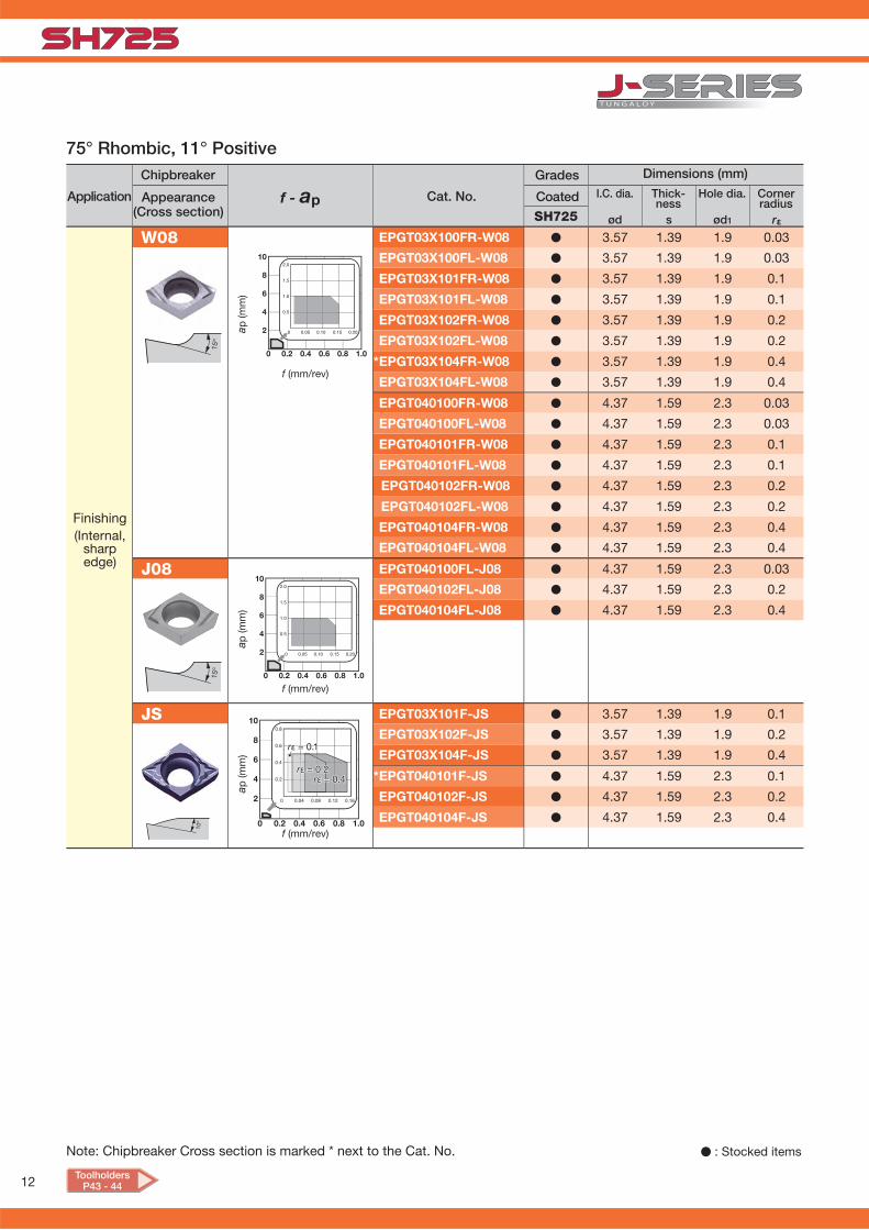
12
f - apød s ød1 rεSH725
W08 EPGT03X100FR-W08 � 3.57 1.39 1.9 0.03
EPGT03X100FL-W08 � 3.57 1.39 1.9 0.03
EPGT03X101FR-W08 � 3.57 1.39 1.9 0.1
EPGT03X101FL-W08 � 3.57 1.39 1.9 0.1
EPGT03X102FR-W08 � 3.57 1.39 1.9 0.2
EPGT03X102FL-W08 � 3.57 1.39 1.9 0.2
*EPGT03X104FR-W08 � 3.57 1.39 1.9 0.4
EPGT03X104FL-W08 � 3.57 1.39 1.9 0.4
EPGT040100FR-W08 � 4.37 1.59 2.3 0.03
EPGT040100FL-W08 � 4.37 1.59 2.3 0.03
EPGT040101FR-W08 � 4.37 1.59 2.3 0.1
EPGT040101FL-W08 � 4.37 1.59 2.3 0.1
EPGT040102FR-W08 � 4.37 1.59 2.3 0.2
EPGT040102FL-W08 � 4.37 1.59 2.3 0.2
EPGT040104FR-W08 � 4.37 1.59 2.3 0.4
EPGT040104FL-W08 � 4.37 1.59 2.3 0.4
J08 EPGT040100FL-J08 � 4.37 1.59 2.3 0.03
EPGT040102FL-J08 � 4.37 1.59 2.3 0.2
EPGT040104FL-J08 � 4.37 1.59 2.3 0.4
JS EPGT03X101F-JS � 3.57 1.39 1.9 0.1
EPGT03X102F-JS � 3.57 1.39 1.9 0.2
EPGT03X104F-JS � 3.57 1.39 1.9 0.4
*EPGT040101F-JS � 4.37 1.59 2.3 0.1
EPGT040102F-JS � 4.37 1.59 2.3 0.2
EPGT040104F-JS � 4.37 1.59 2.3 0.4
10º 0 0.2 0.4 0.6 0.8 1.0
10
8
6
4
2 0 0.04 0.08 0.12 0.16
0.8
0.6
0.4
0.2
rε = 0.1
rε = 0.2rε = 0.4
15º
0 0.2 0.4 0.6 0.8 1.0
10
8
6
4
2
15º
0 0.2 0.4 0.6 0.8 1.0
10
8
6
4
2
75° Rhombic, 11° Positive
a p (m
m)
f (mm/rev)
Finishing (Internal,
sharp edge)
I.C. dia. Thick-ness
Hole dia. Corner radius
Dimensions (mm)Grades
CoatedApplication
Chipbreaker
Appearance (Cross section)
Cat. No.
a p (m
m)
f (mm/rev)
a p (m
m)
f (mm/rev)
� : Stocked itemsNote: Chipbreaker Cross section is marked * next to the Cat. No.
ToolholdersP43 - 44

13
f - apød s ød1 rεSH725
01 * TCGT110202F-01 � 6.35 2.38 2.8 0.2
JS TCGT110200FN-JS � 6.35 2.38 2.8 0.03
* TCGT110201FN-JS � 6.35 2.38 2.8 0.1
TCGT110202FN-JS � 6.35 2.38 2.8 0.2
TCGT110204FN-JS � 6.35 2.38 2.8 0.4
J08 *TCGT080200FR-J08 � 4.76 2.38 2.3 0.03
TCGT080200FL-J08 � 4.76 2.38 2.3 0.03
TCGT080201FR-J08 � 4.76 2.38 2.3 0.1
TCGT080201FL-J08 � 4.76 2.38 2.3 0.1
TCGT080202FR-J08 � 4.76 2.38 2.3 0.2
TCGT080202FL-J08 � 4.76 2.38 2.3 0.2
TCGT080204FR-J08 � 4.76 2.38 2.3 0.4
J10 *TCGT110200FR-J10 � 6.35 2.38 2.8 0.03
TCGT110200FL-J10 � 6.35 2.38 2.8 0.03
TCGT110201FR-J10 � 6.35 2.38 2.8 0.1
TCGT110201FL-J10 � 6.35 2.38 2.8 0.1
TCGT110202FR-J10 � 6.35 2.38 2.8 0.2
TCGT110202FL-J10 � 6.35 2.38 2.8 0.2
TCGT110204FR-J10 � 6.35 2.38 2.8 0.4
TCGT110300FR-J10 � 6.35 2.38 2.8 0.03
TCGT110300FL-J10 � 6.35 2.38 2.8 0.03
TCGT110301FR-J10 � 6.35 2.38 2.8 0.1
TCGT110301FL-J10 � 6.35 2.38 2.8 0.1
TCGT110302FR-J10 � 6.35 2.38 2.8 0.2
TCGT110302FL-J10 � 6.35 2.38 2.8 0.2
0 0.2 0.4 0.6 0.8 1.0
10
8
6
4
2
30º
30º 0 0.2 0.4 0.6 0.8 1.0
10
8
6
4
2
0 0.2 0.4 0.6 0.8 1.0
10
8
6
4
20 0.05 0.1 0.15 0.2
4
3
2
1
rε = 0.1rε = 0.2
rε = 0.4
rε = 0.3
9º
10º
0 0.2 0.4 0.6 0.8 1.0
10
8
6
4
2
0 0.1 0.2 0.3
321
Finishingto
medium cutting
(External, sharp edge)
a p (m
m)
f (mm/rev)
a p (m
m)
f (mm/rev)
a p (m
m)
f (mm/rev)
60° Triangular, 7° positive
I.C. dia. Thick-ness
Hole dia. Corner radius
Dimensions (mm)Grades
CoatedApplication
Chipbreaker
Appearance (Cross section)
Cat. No.
a p (m
m)
f (mm/rev)
Precision fi nishing(External,
sharp edge)
� : Stocked itemsNote: Chipbreaker Cross section is marked * next to the Cat. No.
ToolholdersP33 - 34

14
f - apød s ød1 rεSH725
W08 *TPGT070100FR-W08 � 4.37 1.59 2.58 0.03
TPGT070100FL-W08 � 4.37 1.59 2.58 0.03
TPGT070101FR-W08 � 4.37 1.59 2.58 0.1
TPGT070101FL-W08 � 4.37 1.59 2.58 0.1
TPGT070102FR-W08 � 4.37 1.59 2.58 0.2
TPGT070102FL-W08 � 4.37 1.59 2.58 0.2
TPGT070104FR-W08 � 4.37 1.59 2.58 0.4
TPGT070104FL-W08 � 4.37 1.59 2.58 0.4
JS *TPGT070101F-JS � 4.37 1.59 2.58 0.1
TPGT070102F-JS � 4.37 1.59 2.58 0.2
TPGT070104F-JS � 4.37 1.59 2.58 0.4
10º
0 0.2 0.4 0.6 0.8 1.0
10
8
6
4
2 0 0.04 0.08 0.12 0.16
0.8
0.6
0.4
0.2
rε = 0.1
rε = 0.2rε = 0.4
15º
0 0.2 0.4 0.6 0.8 1.0
10
8
6
4
2
f - apød s ød1 rεSH725
W08 WBGT030100FR-W08 � 5.56 1.59 2.3 0.03
WBGT030100FL-W08 � 5.56 1.59 2.3 0.03
WBGT030101FR-W08 � 5.56 1.59 2.3 0.1
WBGT030101FL-W08 � 5.56 1.59 2.3 0.1
* WBGT030102FR-W08 � 5.56 1.59 2.3 0.2
WBGT030102FL-W08 � 5.56 1.59 2.3 0.2
WBGT030104FR-W08 � 5.56 1.59 2.3 0.4
WBGT030104FL-W08 � 5.56 1.59 2.3 0.4
JS * WBGT030101FR-JS � 5.56 1.59 2.3 0.1
WBGT030101FL-JS � 5.56 1.59 2.3 0.1
WBGT030102FR-JS � 5.56 1.59 2.3 0.2
WBGT030102FL-JS � 5.56 1.59 2.3 0.2
WBGT030104FR-JS � 5.56 1.59 2.3 0.4
WBGT030104FL-JS � 5.56 1.59 2.3 0.4
0 0.2 0.4 0.6 0.8 1.0
10
8
6
4
2
15º
10º
0 0.2 0.4 0.6 0.8 1.0
10
8
6
4
2 0 0.04 0.08 0.12 0.16
0.8
0.6
0.4
0.2
rε = 0.1
rε = 0.2rε = 0.4
60° Triangular, 11° positive
a p (m
m)
f (mm/rev)
Application
Chipbreaker
Appearance (Cross section)
Cat. No. I.C. dia. Thick-ness
Hole dia. Corner radius
Dimensions (mm)Grades
Coated
a p (m
m)
f (mm/rev)Finishing(Internal,
sharp edge)
� : Stocked itemsNote: Chipbreaker Cross section is marked * next to the Cat. No.
80° Trigon, 5° positive
Application
Chipbreaker
Appearance (Cross section)
Cat. No. I.C. dia. Thick-ness
Hole dia. Corner radius
Dimensions (mm)Grades
Coated
Finishing(Internal,
sharp edge)
a p (m
m)
f (mm/rev)
a p (m
m)
f (mm/rev)
ToolholdersP42 - 43

15
f - apød s ød1 rεSH725
JS VBGT110300FN-JS � 6.4 3.18 2.8 0.03
*VBGT110301FN-JS � 6.4 3.18 2.8 0.1
VBGT110302FN-JS � 6.4 3.18 2.8 0.2
VBGT110304FN-JS � 6.4 3.18 2.8 0.4
J10 VBGT110300FR-J10 � 6.4 3.18 2.8 0.03
VBGT110300FL-J10 � 6.4 3.18 2.8 0.03
*VBGT110301FR-J10 � 6.4 3.18 2.8 0.1
VBGT110301FL-J10 � 6.4 3.18 2.8 0.1
VBGT110302FR-J10 � 6.4 3.18 2.8 0.2
VBGT110302FL-J10 � 6.4 3.18 2.8 0.2
VBGT110304FR-J10 � 6.4 3.18 2.8 0.4
VBGT110304FL-J10 � 6.4 3.18 2.8 0.4
9º
0 0.2 0.4 0.6 0.8 1.0
10
8
6
4
20 0.05 0.1 0.15 0.2
4
3
2
1
rε = 0.1rε = 0.2
rε = 0.4
rε = 0.3
30º 0 0.2 0.4 0.6 0.8 1.0
10
8
6
4
2
f - apød s ød1 rεSH725
JRP VPET0802008MFR-JRP � 4.76 2.38 2.3 < 0.08*
JPP
VPET0802008MFL-JRP � 4.76 2.38 2.3 < 0.08*
VPET080201MFR-JRP � 4.76 2.38 2.3 < 0.1*
VPET080201MFL-JRP � 4.76 2.38 2.3 < 0.1*
VPET0802018MFR-JRP � 4.76 2.38 2.3 < 0.18*
VPET0802018MFL-JRP � 4.76 2.38 2.3 < 0.18*
VPET080202MFR-JRP � 4.76 2.38 2.3 < 0.2*
VPET080202MFL-JRP � 4.76 2.38 2.3 < 0.2*
VPET1103008MFR-JRP � 6.35 3.18 2.8 < 0.08*
VPET1103008MFL-JRP � 6.35 3.18 2.8 < 0.08*
VPET110301MFR-JRP � 6.35 3.18 2.8 < 0.1*
VPET110301MFL-JRP � 6.35 3.18 2.8 < 0.1*
VPET1103018MFR-JRP � 6.35 3.18 2.8 < 0.18*
VPET1103018MFL-JRP � 6.35 3.18 2.8 < 0.18*
*VPET110302MFR-JRP � 6.35 3.18 2.8 < 0.2*
VPET110302MFL-JRP � 6.35 3.18 2.8 < 0.2*
10º
0 0.2 0.4 0.6 0.8 1.0
10
8
6
4
2 0 0.02 0.04 0.06 0.08 0.1
0.5
0.4
0.3
0.2
0.1
rε = 0.8 rε = 0.18
rε = 0.1 rε = 0.2
Finishingto
medium cutting
(External, sharp edge)
35° Rhombic, 5° Positive
a p (m
m)
f (mm/rev)
I.C. dia. Thick-ness
Hole dia. Corner radius
Dimensions (mm)Grades
CoatedApplication
Chipbreaker
Appearance (Cross section)
Cat. No.
a p (m
m)
f (mm/rev)
� : Stocked items
35° Rhombic, 11° Positive
I.C. dia. Thick-ness
Hole dia. Corner radius
Dimensions (mm)Grades
CoatedApplication
Chipbreaker
Appearance (Cross section)
Cat. No.
a p (m
m)
f (mm/rev)Finishing(External,
sharp edge)
Note: Chipbreaker Cross section is marked * next to the Cat. No.
* Minus tolerance of corner radius.
ToolholdersP34 - 38

16
f - apød s ød1 rεSH725
JPP VPET0802008MFR-JPP � 4.76 2.38 2.3 < 0.08*
VPET0802008MFL-JPP � 4.76 2.38 2.3 < 0.08*
VPET080201MFR-JPP � 4.76 2.38 2.3 < 0.1*
VPET080201MFL-JPP � 4.76 2.38 2.3 < 0.1*
VPET0802018MFR-JPP � 4.76 2.38 2.3 < 0.18*
VPET0802018MFL-JPP � 4.76 2.38 2.3 0.18*
VPET080202MFR-JPP � 4.76 2.38 2.3 < 0.2*
VPET080202MFL-JPP � 4.76 2.38 2.3 < 0.2*
VPET1103008MFR-JPP � 6.35 3.18 2.8 < 0.08*
VPET1103008MFL-JPP � 6.35 3.18 2.8 < 0.08*
VPET110301MFR-JPP � 6.35 3.18 2.8 < 0.1*
VPET110301MFL-JPP � 6.35 3.18 2.8 < 0.1*
VPET1103018MFR-JPP � 6.35 3.18 2.8 < 0.18*
VPET1103018MFL-JPP � 6.35 3.18 2.8 < 0.18*
*VPET110302MFR-JPP � 6.35 3.18 2.8 < 0.2*
VPET110302MFL-JPP � 6.35 3.18 2.8 < 0.2*
JSP VPET0802008MFN-JSP � 4.76 2.38 2.3 < 0.08*
VPET080201MFN-JSP � 4.76 2.38 2.3 < 0.1*
VPET0802018MFN-JSP � 4.76 2.38 2.3 < 0.18*
VPET080202MFN-JSP � 4.76 2.38 2.3 < 0.2*
VPET1103008MFN-JSP � 6.35 3.18 2.8 < 0.08*
VPET110301MFN-JSP � 6.35 3.18 2.8 < 0.1*
VPET1103018MFN-JSP � 6.35 3.18 2.8 < 0.18*
*VPET110302MFN-JSP � 6.35 3.18 2.8 < 0.2*
10º
0 0.2 0.4 0.6 0.8 1.0
10
8
6
4
2 0 0.02 0.04 0.06 0.08 0.1
0.5
0.4
0.3
0.2
0.1
rε = 0.8 rε = 0.18
rε = 0.1 rε = 0.2
10º
0 0.2 0.4 0.6 0.8 1.0
10
8
6
4
2 0 0.02 0.04 0.06 0.08 0.1
0.5
0.4
0.3
0.2
0.1
rε = 0.8 rε = 0.18
rε = 0.1 rε = 0.2
f - apød s ød1 rεSH725
JTB JTBR3000F � 9.438 3.18 2.5 0.03
JTBL3000F � 9.438 3.18 2.5 0.03
JTBR3005F � 9.438 3.18 2.5 0.05
JTBL3005F � 9.438 3.18 2.5 0.05
JTBR3010F � 9.438 3.18 2.5 0.1
JTBL3010F � 9.438 3.18 2.5 0.1
JTBR3015F � 9.438 3.18 2.5 0.15
JTBL3015F � 9.438 3.18 2.5 0.15
J10E J10ER005BF � 6.35 3.18 3 0.05
J10EL005BF � 6.35 3.18 3 0.05
J10ER010BF � 6.35 3.18 3 0.1
J10EL010BF � 6.35 3.18 3 0.1
J10ER015BF � 6.35 3.18 3 0.15
J10EL015BF � 6.35 3.18 3 0.15
0 0.2 0.4 0.6 0.8 1.0
10
8
6
4
2
0 0.2 0.4 0.6 0.8 1.0
10
8
6
4
2
Finishing(External,
sharp edge)
� : Stocked items
35° Rhombic, 11° Positive
I.C. dia. Thick-ness
Hole dia. Corner radius
Dimensions (mm)Grades
CoatedApplication
Chipbreaker
Appearance (Cross section)
Cat. No.
a p (m
m)
f (mm/rev)
a p (m
m)
f (mm/rev)
Back turning
Application
Chipbreaker
AppearanceCat. No.
Back turning(sharp edge)
a p (m
m)
a p (m
m)
f (mm/rev)
f (mm/rev)
Note: Chipbreaker Cross section is marked * next to the Cat. No.
* Minus tolerance of corner radius.
ToolholdersP37 - 38
I.C. dia. Thick-ness
Hole dia. Corner radius
Dimensions (mm)Grades
Coated

17
ød s W ar rεSH725JVG JVGR033F � 7.94 3.18 0.33 0.7 -
JVGL033F � 7.94 3.18 0.5 0.7 -
JVGR050F � 7.94 3.18 0.75 1.1 -
JVGL050F � 7.94 3.18 0.95 1.1 -
JVGR075F � 7.94 3.18 1 1.9 -
JVGL075F � 7.94 3.18 1.25 1.9 -
JVGR095F � 7.94 3.18 1.5 1.9 -
JVGL095F � 7.94 3.18 2 1.9 -
JVGR100F � 9.525 3.18 0.33 5.5 -
JVGL100F � 9.525 3.18 0.33 5.5 -
JVGR125F � 9.525 3.18 0.5 5.0 -
JVGL125F � 9.525 3.18 0.5 5.0 -
JVGR150F � 9.525 3.18 0.65 5.5 -
JVGL150F � 9.525 3.18 0.65 5.5 -
JVGR200F � 9.525 3.18 0.75 5.5 -
JVGL200F � 9.525 3.18 0.75 5.5 -
JTG JTGR3033F � 7.94 3.18 0.33 0.7 0.03
JTGR3033F-005 � 7.94 3.18 0.33 0.7 0.05
JTGR3050F � 7.94 3.18 0.5 1.1 0.03
JTGL3050F � 7.94 3.18 0.5 1.1 0.03
JTGR3050F-005 � 7.94 3.18 0.5 1.1 0.05
JTGL3050F-005 � 7.94 3.18 0.5 1.1 0.05
JTGR3065F � 7.94 3.18 0.65 1.9 0.03
JTGR3065F-010 � 7.94 3.18 0.65 1.9 0.1
JTGR3075F � 7.94 3.18 0.75 1.9 0.03
JTGL3075F � 7.94 3.18 0.75 1.9 0.03
JTGR3075F-010 � 7.94 3.18 0.75 1.9 0.1
JTGL3075F-010 � 7.94 3.18 0.75 1.9 0.1
JTGR3080F � 7.94 3.18 0.8 1.9 0.03
JTGR3080F-010 � 7.94 3.18 0.8 1.9 0.1
JTGR3085F � 7.94 3.18 0.85 1.9 0.03
JTGR3095F � 7.94 3.18 0.95 1.9 0.03
JTGL3095F � 7.94 3.18 0.95 1.9 0.03
JTGR3095F-010 � 7.94 3.18 0.95 1.9 0.1
JTGL3095F-010 � 7.94 3.18 0.95 1.9 0.1
JTGR3100F � 7.94 3.18 1 2.1 0.05
JTGL3100F � 7.94 3.18 1 2.1 0.05
JTGR3100F-010 � 7.94 3.18 1 2.1 0.1
JTGL3100F-010 � 7.94 3.18 1 2.1 0.1
JTGR3110F � 7.94 3.18 1.1 2.1 0.05
JTGR3120F � 7.94 3.18 1.2 2.1 0.05
JTGR3120F-010 � 7.94 3.18 1.2 2.1 0.1
Grooving
Application
Chipbreaker
Appearance Cat. No. I.C. dia. Thick-ness
Cutting edgewidth
Corner radius
Dimensions (mm)Grades
Coated
Grooving(sharp edge)
� : Stocked items
Max.groovedepth
ToolholdersP44 - 45

18
ød T θ rεSH725
JTT JTTR3005F-55 � 9.525 3.18 55º 0.05
JTTR3005F � 9.525 3.18 60º 0.05
JTTL3005F � 9.525 3.18 60º 0.1
JTTR3010F � 9.525 3.18 60º 0.1
JTTL3010F � 9.525 3.18 60º 0.1
ød s W ar rεSH725
JTG JTGR3125F � 7.94 3.18 1.25 2.1 0.05
JTGL3125F � 7.94 3.18 1.25 2.1 0.05
JTGR3125F-010 � 7.94 3.18 1.25 2.1 0.1
JTGL3125F-010 � 7.94 3.18 1.25 2.1 0.1
JTGR3130F � 7.94 3.18 1.3 2.1 0.05
JTGR3140F � 7.94 3.18 1.4 2.1 0.05
JTGR3140F-010 � 7.94 3.18 1.4 2.1 0.1
JTGR3145F � 7.94 3.18 1.45 2.1 0.05
JTGR3145F-010 � 7.94 3.18 1.45 2.1 0.1
JTGR3150F � 7.94 3.18 1.5 2.1 0.05
JTGL3150F � 7.94 3.18 1.5 2.1 0.05
JTGR3150F-010 � 7.94 3.18 1.5 2.1 0.1
JTGL3150F-010 � 7.94 3.18 1.5 2.1 0.1
JTGR3175F � 7.94 3.18 1.75 2.1 0.05
JTGR3175F-010 � 7.94 3.18 1.75 2.1 0.1
JTGR3180F � 7.94 3.18 1.8 2.1 0.05
JTGR3200F � 7.94 3.18 2 2.6 0.05
JTGL3200F � 7.94 3.18 2 2.6 0.05
JTGR3200F-010 � 7.94 3.18 2 2.6 0.1
JTGL3200F-010 � 7.94 3.18 2 2.6 0.1
JTGR3225F � 7.94 3.18 2.25 2.6 0.05
JTGR3250F � 7.94 3.18 2.5 2.6 0.05
JTGL3250F � 7.94 3.18 2.5 2.6 0.05
JTGR3250F-010 � 7.94 3.18 2.5 2.6 0.1
JTGL3250F-010 � 7.94 3.18 2.5 2.6 0.1
JTGR3300F � 7.94 3.18 3 2.6 0.05
JTGR3300F-010 � 7.94 3.18 3 2.6 0.1
Threading
Application
Chipbreaker
Appearance Cat. No. I.C. dia. Thick-ness
Cutting edgeangle
Corner radius
Dimensions (mm)Grades
Coated
Threading(sharp edge)
� : Stocked items
Application
Chipbreaker
Appearance Cat. No. I.C. dia. Thick-ness
Cutting edge width
Corner radius
Dimensions (mm)Grades
Coated
Grooving(sharp edge)
Max.groovedepth
Grooving
ToolholdersP44 - 46
19
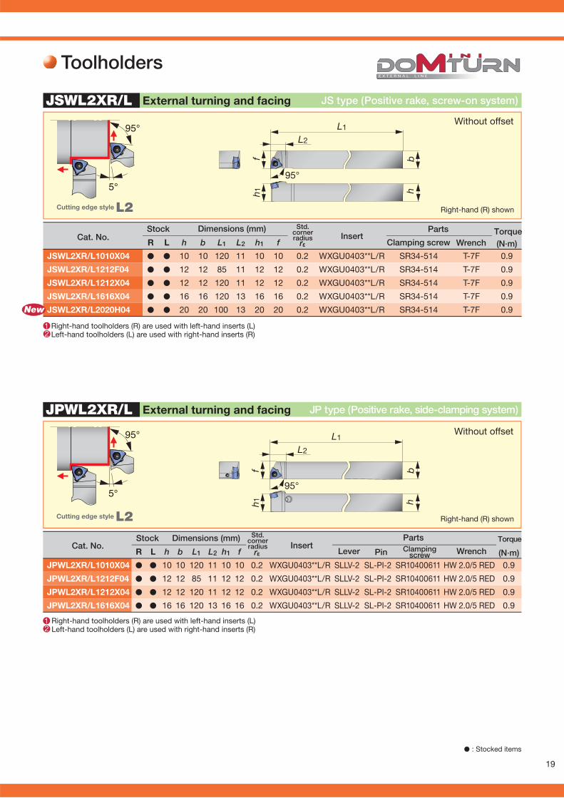
rεR L h b L1 L2 h1 f (N·m)JPWL2XR/L1010X04 � � 10 10 120 11 10 10 0.2 WXGU0403**L/R SLLV-2 SL-PI-2 SR10400611 HW 2.0/5 RED 0.9
JPWL2XR/L1212F04 � � 12 12 85 11 12 12 0.2 WXGU0403**L/R SLLV-2 SL-PI-2 SR10400611 HW 2.0/5 RED 0.9
JPWL2XR/L1212X04 � � 12 12 120 11 12 12 0.2 WXGU0403**L/R SLLV-2 SL-PI-2 SR10400611 HW 2.0/5 RED 0.9
JPWL2XR/L1616X04 � � 16 16 120 13 16 16 0.2 WXGU0403**L/R SLLV-2 SL-PI-2 SR10400611 HW 2.0/5 RED 0.9
95°
5°
h 1f b
h
L1
L2
95°
1 2
JPWL2XR/L
rεR L h b L1 L2 h1 f (N·m)JSWL2XR/L1010X04 � � 10 10 120 11 10 10 0.2 WXGU0403**L/R SR34-514 T-7F 0.9
JSWL2XR/L1212F04 � � 12 12 85 11 12 12 0.2 WXGU0403**L/R SR34-514 T-7F 0.9
JSWL2XR/L1212X04 � � 12 12 120 11 12 12 0.2 WXGU0403**L/R SR34-514 T-7F 0.9
JSWL2XR/L1616X04 � � 16 16 120 13 16 16 0.2 WXGU0403**L/R SR34-514 T-7F 0.9
JSWL2XR/L2020H04 � � 20 20 100 13 20 20 0.2 WXGU0403**L/R SR34-514 T-7F 0.9
95°
5°
L1
L2
bhh 1
f
95°
JSWL2XR/L
New
Cat. No.Stock Dimensions (mm)
InsertPartsClamping
screw WrenchLever Pin
Right-hand (R) shownCutting edge style L2
Without offset
Right-hand toolholders (R) are used with left-hand inserts (L) Left-hand toolholders (L) are used with right-hand inserts (R)
External turning and facing
Torque
Toolholders
Cat. No.Stock Dimensions (mm)
InsertParts
Clamping screw Wrench
Right-hand (R) shownCutting edge style L2
Without offset
Right-hand toolholders (R) are used with left-hand inserts (L) Left-hand toolholders (L) are used with right-hand inserts (R)
1 2
External turning and facing
Torque
� : Stocked items
JS type (Positive rake, screw-on system)
JP type (Positive rake, side-clamping system)
Std. cornerradius
Std. cornerradius

20
rεR L h b L1 L2 L3 L4 h1 f f1 (N·m)JSWLXR1016X04-F15 � 10 16 120 12 27 11 10 15 26 0.2 WXGU0403**L SR34-514 T-7F 0.9
JSWLXR1216F04-F15 � 12 16 85 12 27 11 12 15 26 0.2 WXGU0403**L SR34-514 T-7F 0.9
JSWLXR1216X04-F15 � 12 16 120 12 27 11 12 15 26 0.2 WXGU0403**L SR34-514 T-7F 0.9
JSWLXR1620X04-F15 � 16 20 120 12 27 11 16 15 26 0.2 WXGU0403**L SR34-514 T-7F 0.9
JSWLXR-F
1
hb
L1
L2
h1
L3
L4
f1 f
95°New
JSWL2XR/L-CHP
95°
5°
1 2
hb
f 2f
h 1
L1
L2
95°
5/16”-24UNF
rεR L h b L1 L2 h1 f f2 (N·m)JSWL2XR/L1212F04-CHP � � 12 12 85 18 12 12 16.5 0.2 WXGU0403**L/R SR34-514 T-7F 0.9
Cat. No.Stock Dimensions (mm) Std.
cornerradius Insert
PartsClamping
screw Wrench
Right-hand (R) shownCutting edge style L
Right-hand toolholders (R) are used with left-hand inserts (L)
Torque
� : Stocked items
Neck-down type (Positive rake, screw-on system)External turning and facing
Right-hand toolholders (R) are used with left-hand inserts (L) Left-hand toolholders (L) are used with right-hand inserts (R)
External turning and facing CHP type (Positive rake, screw-on system)
Cutting edge style: L2 Right-hand (R) shown
Without offset
Cat. NoStock Dimensions (mm)
InsertParts
Clamping screw Wrench
Torque
TungJet partsP49 - 50
Works with high-pressure coolant
Std. cornerradius

21
rεR L h b L1 L2 h1 f (N·m)
JSDJ2XR/L1010X07 � � 10 10 120 14 10 10 0.2 DXGU0703**L/R SR34-514 T-7F 0.9
JSDJ2XR/L1212F07 � � 12 12 85 14 12 12 0.2 DXGU0703**L/R SR34-514 T-7F 0.9
JSDJ2XR/L1212X07 � � 12 12 120 14 12 12 0.2 DXGU0703**L/R SR34-514 T-7F 0.9
JSDJ2XR/L1616X07 � � 16 16 120 18 16 16 0.2 DXGU0703**L/R SR34-514 T-7F 0.9
JSDJ2XR/L2020H07 � � 20 20 100 18 20 20 0.2 DXGU0703**L/R SR34-514 T-7F 0.9
h 1f b
h
L1
L2
93°
JSDJ2XR/L
1 2
30°
93°
rεR L h b L1 L2 h1 f (N·m)JPDJ2XR/L1010X07 � � 10 10 120 14 10 10 0.2 DXGU0703**L/R SLLV-2 SL-PI-2 SR10400611 HW 2.0/5 RED 0.9
JPDJ2XR/L1212F07 � � 12 12 85 14 12 12 0.2 DXGU0703**L/R SLLV-2 SL-PI-2 SR10400611 HW 2.0/5 RED 0.9
JPDJ2XR/L1212X07 � � 12 12 120 14 12 12 0.2 DXGU0703**L/R SLLV-2 SL-PI-2 SR10400611 HW 2.0/5 RED 0.9
JPDJ2XR/L1616X07 � � 16 16 120 18 16 16 0.2 DXGU0703**L/R SLLV-2 SL-PI-2 SR10400611 HW 2.0/5 RED 0.9
h 1f b
h
L1
L2
93°
1 2
JPDJ2XR/L
30°
93°
New
Cat. No.Stock Dimensions (mm)
InsertParts
Wrench
Right-hand (R) shownCutting edge style J2
Without offset
Clamping screw
Right-hand toolholders (R) are used with left-hand inserts (L) Left-hand toolholders (L) are used with right-hand inserts (R)
Torque
External turning and profi ling JS type (Positive rake, screw-on system)
Right-hand toolholders (R) are used with left-hand inserts (L) Left-hand toolholders (L) are used with right-hand inserts (R)
� : Stocked items
Right-hand (R) shownCutting edge style J2
Without offset
Cat. No.Stock Dimensions (mm)
InsertParts
Clamping screw WrenchLever Pin
Torque
External turning and profi ling JP type (Positive rake, side-clamping system)
Std. cornerradius
Std. cornerradius

22
rεR L h b L1 L2 L3 L4 h1 f f1 (N·m)JSDJXR1016X07-F15 � 10 16 120 12 27 14 10 15 26 0.2 DXGU0703**L SR34-514 T-7F 0.9
JSDJXR1216F07-F15 � 12 16 85 12 27 14 12 15 26 0.2 DXGU0703**L SR34-514 T-7F 0.9
JSDJXR1216X07-F15 � 12 16 120 12 27 14 12 15 26 0.2 DXGU0703**L SR34-514 T-7F 0.9
JSDJXR1620X07-F15 � 16 20 120 12 27 14 16 15 26 0.2 DXGU0703**L SR34-514 T-7F 0.9
1
JSDJXR-F
hh1
L4
b
L1
L2
L3
f1 f
New30°
93°
JSDJ2XR/L-CHP
1 2
h
b
h 1
L2
L1
93°
ff 2
5/16”-24UNF
30°
93°
rεR L h b L1 L2 h1 f f2 (N·m)JSDJ2XR/L1212F07-CHP � � 12 12 85 19 12 12 18.5 0.2 DXGU0703**L/R SR34-514 T-7F 0.9
� : Stocked items
Cat. No.Stock Dimensions (mm)
InsertParts
Clamping screw Wrench
Right-hand (R) shownCutting edge style J
Right-hand toolholders (R) are used with left-hand inserts (L)
Torque
External turning and profi ling Neck-down type (Positive rake, screw-on system)
Right-hand toolholders (R) are used with left-hand inserts (L) Left-hand toolholders (L) are used with right-hand inserts (R)
External turning and profi ling CHP type (Positive rake, screw-on system)
Cutting edge style: J2 Right-hand (R) shown
Without offset
Cat. NoStock Dimensions (mm)
InsertParts
Clamping screw Wrench
Torque
TungJet partsP49 - 50
Works with high-pressure coolant
Std. cornerradius
Std. cornerradius

23
rεR L h b L1 L2 h1 f (N·m)JSVJ2XR/L1010X09 � � 10 10 120 17 10 10 0.2 VXGU09T2**L/R SR34-508 T-7F 0.9
JSVJ2XR/L1212F09 � � 12 12 85 19 12 12 0.2 VXGU09T2**L/R SR34-508 T-7F 0.9
JSVJ2XR/L1212X09 � � 12 12 120 19 12 12 0.2 VXGU09T2**L/R SR34-508 T-7F 0.9
JSVJ2XR/L1616X09 � � 16 16 120 19 16 16 0.2 VXGU09T2**L/R SR34-508 T-7F 0.9
JSVJ2XR/L2020H09 � � 20 20 100 19 20 20 0.2 VXGU09T2**L/R SR34-508 T-7F 0.9
JSVJ2XR/L
New
L1
fh1
bh
L2
1 2
30°
93°
rεR L h b L1 L2 h1 f (N·m)JPVJ2XR/L1010X09 � � 10 10 120 19 10 10 0.2 VXGU09T2**L/R SLLV-1 SL-PI-2 SR 10400611 HW 2.0/5 RED 0.9
JPVJ2XR/L1212F09 � � 12 12 85 19 12 12 0.2 VXGU09T2**L/R SLLV-1 SL-PI-2 SR 10400611 HW 2.0/5 RED 0.9
JPVJ2XR/L1212X09 � � 12 12 120 19 12 12 0.2 VXGU09T2**L/R SLLV-1 SL-PI-2 SR 10400611 HW 2.0/5 RED 0.9
JPVJ2XR/L1616X09 � � 16 16 120 19 16 16 0.2 VXGU09T2**L/R SLLV-1 SL-PI-2 SR 10400611 HW 2.0/5 RED 0.9
JPVJ2XR/L
New
L1
fh1
bh
L2
1 2
50°
93°
Right-hand toolholders (R) are used with left-hand inserts (L) Left-hand toolholders (L) are used with right-hand inserts (R)
Right-hand toolholders (R) are used with left-hand inserts (L) Left-hand toolholders (L) are used with right-hand inserts (R)
Right-hand (R) shown
Without offset
Cat. No.Stock Dimensions (mm)
InsertParts
Clamping screw Wrench
External turning and profi ling
Torque
Cutting edge style L
JS type (Positive rake, screw-on system)
Without offset
Cat. No.Stock Dimensions (mm)
InsertParts
Clamping screw WrenchLever Pin
External turning and profi ling
Torque
JP type (Positive rake, side-clamping system)
Cutting edge style J
� : Stocked items
Std. cornerradius
Std. cornerradius
24
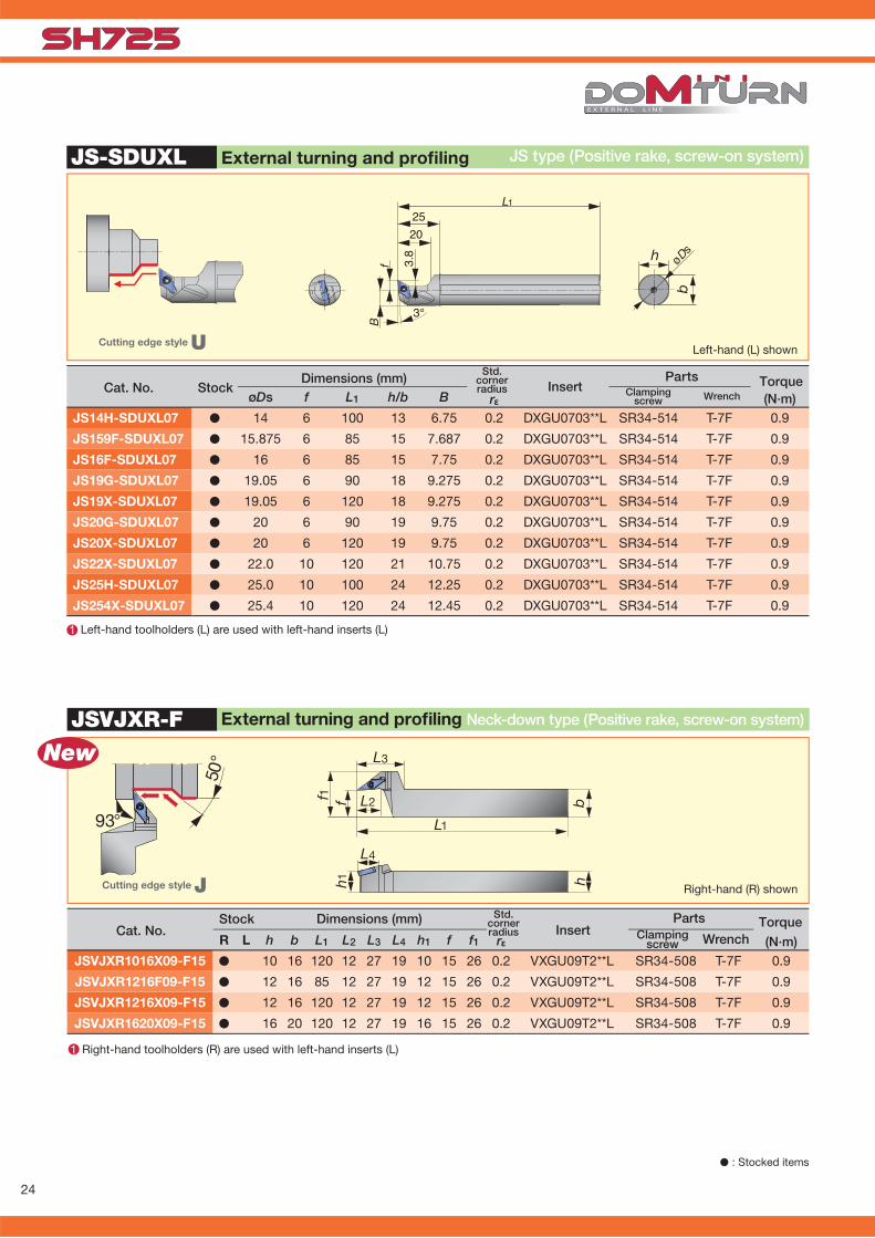
rεR L h b L1 L2 L3 L4 h1 f f1 (N·m)JSVJXR1016X09-F15 � 10 16 120 12 27 19 10 15 26 0.2 VXGU09T2**L SR34-508 T-7F 0.9
JSVJXR1216F09-F15 � 12 16 85 12 27 19 12 15 26 0.2 VXGU09T2**L SR34-508 T-7F 0.9
JSVJXR1216X09-F15 � 12 16 120 12 27 19 12 15 26 0.2 VXGU09T2**L SR34-508 T-7F 0.9
JSVJXR1620X09-F15 � 16 20 120 12 27 19 16 15 26 0.2 VXGU09T2**L SR34-508 T-7F 0.9
JSVJXR-F
hh1
L4
L3
f1 f L2
L1
b
New
1
50°
93°
rεøDs f L1 h/b B (N·m)JS14H-SDUXL07 � 14 6 100 13 6.75 0.2 DXGU0703**L SR34-514 T-7F 0.9
JS159F-SDUXL07 � 15.875 6 85 15 7.687 0.2 DXGU0703**L SR34-514 T-7F 0.9
JS16F-SDUXL07 � 16 6 85 15 7.75 0.2 DXGU0703**L SR34-514 T-7F 0.9
JS19G-SDUXL07 � 19.05 6 90 18 9.275 0.2 DXGU0703**L SR34-514 T-7F 0.9
JS19X-SDUXL07 � 19.05 6 120 18 9.275 0.2 DXGU0703**L SR34-514 T-7F 0.9
JS20G-SDUXL07 � 20 6 90 19 9.75 0.2 DXGU0703**L SR34-514 T-7F 0.9
JS20X-SDUXL07 � 20 6 120 19 9.75 0.2 DXGU0703**L SR34-514 T-7F 0.9
JS22X-SDUXL07 � 22.0 10 120 21 10.75 0.2 DXGU0703**L SR34-514 T-7F 0.9
JS25H-SDUXL07 � 25.0 10 100 24 12.25 0.2 DXGU0703**L SR34-514 T-7F 0.9
JS254X-SDUXL07 � 25.4 10 120 24 12.45 0.2 DXGU0703**L SR34-514 T-7F 0.9
1
JS-SDUXL
20
3.8
25
fB
øDs
L1
3°
b
h
� : Stocked items
TorqueCat. No.
Stock Dimensions (mm)Insert
PartsClamping
screw Wrench
Right-hand (R) shownCutting edge style J
Right-hand toolholders (R) are used with left-hand inserts (L)
External turning and profi ling Neck-down type (Positive rake, screw-on system)
Left-hand (L) shownCutting edge style U
Cat. No. StockDimensions (mm)
InsertParts
Left-hand toolholders (L) are used with left-hand inserts (L)
Clampingscrew Wrench
External turning and profi ling JS type (Positive rake, screw-on system)
TorqueStd.
cornerradius
Std. cornerradius

25
rεR L h b L1 L2 h1 f f2 (N·m)JSVJ2XR/L1212F09-CHP � � 12 12 85 17.5 12 12 13.5 0.2 VXGU09T2**L/R SR34-508 T-7F 0.9
JSVJ2XR/L-CHP
hb
f 2f
h 1
L2L1
95°
5/16”-24UNF
1 2
50°
93°
New
rεøDs f L1 h/b B (N·m)JS159F-SVUXL09 � 15.875 10 85 15 7.7 0.2 VXGU09T2**L SR34-508 T-7F 0.9
JS16F-SVUXL09 � 16 10 85 15 7.7 0.2 VXGU09T2**L SR34-508 T-7F 0.9
JS19G-SVUXL09 � 19.05 10 90 18 9.2 0.2 VXGU09T2**L SR34-508 T-7F 0.9
JS19X-SVUXL09 � 19.05 10 120 18 9.2 0.2 VXGU09T2**L SR34-508 T-7F 0.9
JS20G-SVUXL09 � 20 10 90 19 9.7 0.2 VXGU09T2**L SR34-508 T-7F 0.9
JS20X-SVUXL09 � 20 10 120 19 9.7 0.2 VXGU09T2**L SR34-508 T-7F 0.9
JS22X-SVUXL09 � 22 10 120 21 10.7 0.2 VXGU09T2**L SR34-508 T-7F 0.9
JS25H-SVUXL09 � 25 10 100 24 12.2 0.2 VXGU09T2**L SR34-508 T-7F 0.9
JS254X-SVUXL09 � 25.4 10 120 24 12.4 0.2 VXGU09T2**L SR34-508 T-7F 0.9
JS-SVUXL
20
7.5
25L1
fB
3°
b
h øDs
New
1
Cutting edge style J
CHP type (Positive rake, screw-on system)
Without offset
Cat. NoStock Dimensions (mm)
InsertParts
Clamping screw Wrench
External turning and profi ling
Torque
Right-hand toolholders (R) are used with left-hand inserts (L) Left-hand toolholders (L) are used with right-hand inserts (R)
� : Stocked items★ : Available in 2015
Left-hand (L) shown
Cat. No. Stock Dimensions (mm) InsertParts Torque
Clampingscrew Wrench
Left-hand toolholders (L) are used with left-hand inserts (L)
Cutting edge style U
External turning and profi ling JS type (Positive rake, screw-on system)
TungJet partsP49 - 50
Works with high-pressure coolant
Std. cornerradius
Std. cornerradius

26
JTCL2CR/L
JSCL2CR/L
95°
5° L1L2
bh
fh 1
95°
95°
5°
b
L1L2
h1f
h
95°
rε (N·m)R L h b L1 L2 h1 fJTCL2CR/L0810K06 � � 8 10 125 12 8 10 0.4 CC**0602 JCP-2 JDS-3525 P-2F 0.9
JTCL2CR/L1010X06 � � 10 10 120 12 10 10 0.2 CC**0602 JCP-2 JDS-3525 P-2F 0.9
JTCL2CR/L1010K06 � � 10 10 125 12 10 10 0.4 CC**0602 JCP-2 JDS-3525 P-2F 0.9
JTCL2CR/L1212F09 � � 12 12 85 16 12 12 0.2 CC**09T3 JCP-3 JDS-5040 P-2.5F 1.2
JTCL2CR/L1212X09 � � 12 12 120 16 12 12 0.2 CC**09T3 JCP-3 JDS-5040 P-2.5F 1.2
JTCL2CR/L1212M09 � � 12 12 150 16 12 12 0.8 CC**09T3 JCP-3 JDS-5040 P-2.5F 1.2
JTCL2CR/L1616X09 � � 16 16 120 16 16 16 0.2 CC**09T3 JCP-3 JDS-5040 P-2.5F 1.2
JTCL2CR/L1616M09 � � 16 16 125 16 16 16 0.8 CC**09T3 JCP-3 JDS-5040 P-2.5F 1.2
New
New
New
New
rε (N·m)R L h b L1 L2 h1 fJSCL2CR/L1010X06 � � 10 10 120 12 10 10 0.2 CC**0602 CSTB-2.5 T-8F 1.2
JSCL2CR/L1010K06 � � 10 10 125 12 10 10 0.4 CC**0602 CSTB-2.5 T-8F 1.2
JSCL2CR/L1212F06 � � 12 12 85 12 12 12 0.2 CC**0602 CSTB-2.5 T-8F 1.2
JSCL2CR/L1212X06 � � 12 12 120 12 12 12 0.2 CC**0602 CSTB-2.5 T-8F 1.2
JSCL2CR/L1212K06 � � 12 12 125 12 12 12 0.4 CC**0602 CSTB-2.5 T-8F 1.2
JSCL2CR/L1212F09 � � 12 12 85 16 12 12 0.2 CC**09T3 CSTB-4SD T-8F 1.2
JSCL2CR/L1212X09 � � 12 12 120 16 12 12 0.2 CC**09T3 CSTB-4SD T-8F 1.2
JSCL2CR/L1616X09 � � 16 16 120 16 16 16 0.2 CC**09T3 CSTB-4SD T-8F 1.2
New
New
New
New
New
New
Without offset
Without offset
External turning and facing
External turning and facing
JT type (Positive rake, back-clamping system)
JS type (Positive rake, screw-on system)
Cutting edge style L2 Right-hand (R) shown
Cutting edge style L2 Right-hand (R) shown
� : Stocked items
Torque Parts Clamp Clamping Wrench screw
InsertStandard
cornerradiusCat. No.
Dimensions (mm)Stock
InsertStandard
cornerradius
Parts Torque Clamping Wrench screw
Cat. No.Dimensions (mm)Stock

27
JSCLCR/L
JSCLCR
New
h1 hb
L1
f
L295°
95°
5°
f1
h
L1L4
b
fh 1
L3
L2
95°
rε (N·m)R L h b L1 L2 h1 fJSCLCR/L0808H06 � � 8 8 100 12 8 10 0.4 CC**0602 CSTB-2.5 T-8F 1.2
JSCLCR/L1010H06 � � 10 10 100 12 10 12 0.4 CC**0602 CSTB-2.5 T-8F 1.2
JSCLCR/L1212H09 � � 12 12 100 16 12 16 0.8 CC**09T3 CSTB-4SD T-8F 1.2
JSCLCR/L1616H09 � � 16 16 100 16 16 20 0.8 CC**09T3 CSTB-4SD T-8F 1.2
rε (N·m)h b L1 L2 L3 L4 h1 f f1JSCLCR1216F09-F15 � 12 16 85 12 27 12.5 12 15 28 0.2 CC**09T3** CSTB-4SD T-8F 1.2JSCLCR1216X09-F15 � 12 16 120 12 27 12.5 12 15 28 0.2 CC**09T3** CSTB-4SD T-8F 1.2JSCLCR1620X09-F15 � 16 20 120 12 27 12.5 16 15 28 0.2 CC**09T3** CSTB-4SD T-8F 1.2
External turning and facing JS type (Positive rake, screw-on system)
Cutting edge style L
External turning and facing Neck-down type (Positive rake, screw-on system)
Right-hand (R) shown
Cutting edge style L Right-hand (R) shown
InsertStandard
cornerradius
Parts Torque Clamping Wrench screw
Cat. No.Dimensions (mm)Stock
TorqueInsertStandard
cornerradius
Parts Clamping Wrench screw
Cat. No.Dimensions (mm)
Stock
� : Stocked items★ : Available in 2015

28
JSCGCR/L
f
L1
b
h 1 h
L291°
91°
JSCACR/L
L1L2
bfh1
90°
h
90°
rε (N·m)R L h b L1 L2 h1 fJSCACR/L0808H06 � � 8 8 100 12 8 8 0.4 CC**0602 CSTB-2.5 T-8F 1.2JSCACR/L1010H06 � � 10 10 100 12 10 10 0.4 CC**0602 CSTB-2.5 T-8F 1.2JSCACR/L1212H09 � � 12 12 100 16 12 12 0.8 CC**09T3 CSTB-4SD T-8F 1.2
rε (N·m)R L h b L1 L2 h1 fJSCGCR/L1212H06 � � 12 12 100 12 12 16 0.4 CC**0602 CSTB-2.5 T-8F 1.2
JSCGCR/L1616H09 � � 16 16 100 16 16 20 0.8 CC**09T3 CSTB-4SD T-8F 1.2
External turning JS type (Positive rake, screw-on system)
Right-hand (R) shownCutting edge style G
Without offset
External turning JS type (Positive rake, screw-on system)
Cutting edge style A Right-hand (R) shown
� : Stocked items
InsertStandard
cornerradius
Parts Torque Clamping Wrench screw
Cat. No.Dimensions (mm)Stock
InsertStandard
cornerradius
Parts Torque Clamping Wrench screw
Cat. No.Dimensions (mm)Stock

29
JTDJ2CR/L
L1L2
bhh1
93°
f
30°93°
JSDJ2CR/L
rε (N·m)R L h b L1 L2 h1 f f2JSDJ2CR/L0808F07 � � 8 8 85 14 8 8 - 0.2 DC**0702 CSTB-2.5 T-8F 1.2
JSDJ2CR/L1010K07 � � 10 10 125 14 10 10 - 0.4 DC**0702 CSTB-2.5 T-8F 1.2
JSDJ2CR/L1010X07 � � 10 10 120 14 10 10 - 0.2 DC**0702 CSTB-2.5 T-8F 1.2
JSDJ2CR/L1010X11 � � 10 10 120 20 10 10 4 0.2 DC**11T3 CSTB-4SD T-8F 1.2
JSDJ2CR/L1212F07 � � 12 12 85 14 12 12 - 0.2 DC**0702 CSTB-2.5 T-8F 1.2
JSDJ2CR/L1212F11 � � 12 12 85 20 12 12 2 0.2 DC**11T3 CSTB-4SD T-8F 1.2
JSDJ2CR/L1212X07 � � 12 12 120 14 12 12 - 0.2 DC**0702 CSTB-2.5 T-8F 1.2
JSDJ2CR/L1212K07 � � 12 12 125 14 12 12 - 0.4 DC**0702 CSTB-2.5 T-8F 1.2
JSDJ2CR/L1212X11 � � 12 12 120 20 12 12 2 0.2 DC**11T3 CSTB-4SD T-8F 1.2
JSDJ2CR/L1616X11 � � 16 16 120 20 16 16 - 0.2 DC**11T3 CSTB-4SD T-8F 1.2
JSDJ2CR/L1010F07JSDJ2CR/L1212F11JSDJ2CR/L1212X11
f2
bhh1
L1
f
L293°
93°
30°
rε (N·m)R L h b L1 L2 h1 f f2JTDJ2CR/L0810K07 � � 8 10 125 14 8 10 - 0.4 DC**0702 JCP-2 JDS-3525 P-2F 0.9
JTDJ2CR/L1010X07 � � 10 10 120 14 10 10 - 0.2 DC**0702 JCP-2 JDS-3525 P-2F 0.9
JTDJ2CR/L1010K07 � � 10 10 125 14 10 10 - 0.4 DC**0702 JCP-2 JDS-3525 P-2F 0.9
JTDJ2CR/L1212F07 � � 12 12 85 14 12 12 - 0.2 DC**0702 JCP-2 JDS-3525 P-2F 0.9
JTDJ2CR/L1212X07 � � 12 12 120 14 12 12 - 0.2 DC**0702 JCP-2 JDS-3525 P-2F 0.9
JTDJ2CR/L1212F11 � � 12 12 85 20 12 12 2 0.2 DC**11T3 JCP-3 JDS-5040 P-2.5F 1.2
JTDJ2CR/L1212X11 � � 12 12 120 20 12 12 2 0.2 DC**11T3 JCP-3 JDS-5040 P-2.5F 1.2
JTDJ2CR/L1212M11 � � 12 12 150 20 12 12 - 0.8 DC**11T3 JCP-3 JDS-5040 P-2.5F 1.2
JTDJ2CR/L1616X11 � � 16 16 120 20 16 16 - 0.2 DC**11T3 JCP-3 JDS-5040 P-2.5F 1.2
JTDJ2CR/L1616M11 � � 16 16 150 20 16 16 - 0.8 DC**11T3 JCP-3 JDS-5040 P-2.5F 1.2
New
New
New
New
New
New
f2
JTDJ2CR/L1212F11JTDJ2CR/L1212X11
New
NewNew
New
New
New
New
New
Without offset
External turning and profi ling JT type (Positive rake, back-clamping system)
Right-hand (R) shownCutting edge style J2
Without offset
Right-hand (R) shown
External profi ling JS type (Positive rake, screw-on system)
Stock Dimensions (mm) Cat. No. Insert
Standardcornerradius
Parts Torque Clamping Wrench screw
Cutting edge style J2
� : Stocked items
InsertStandard
cornerradius
Parts Clamp Clamping Wrench screw
Cat. No.Dimensions (mm)Stock Torque
30
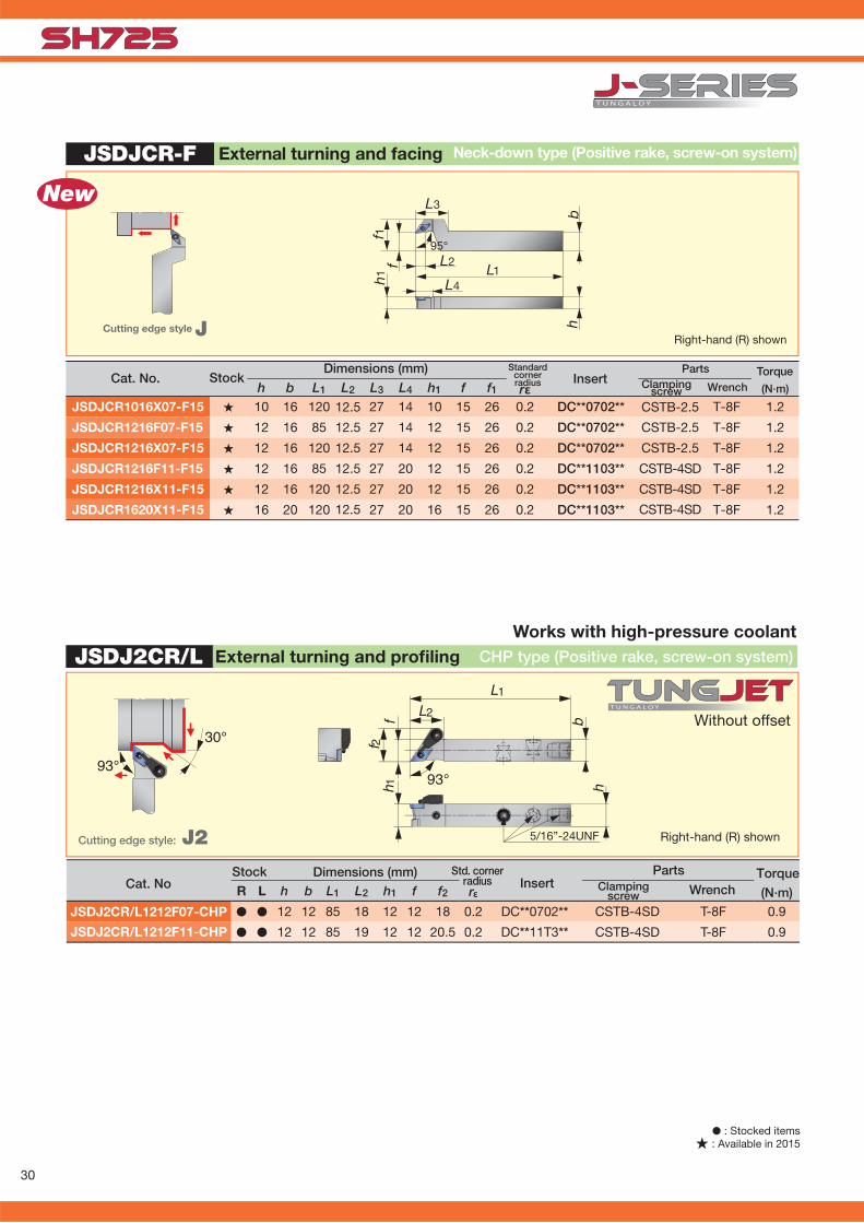
JSDJCR-F
New
f1
h
L1L4
b
fh1
L3
L295°
rε (N·m)h b L1 L2 L3 L4 h1 f f1JSDJCR1016X07-F15 � 10 16 120 12.5 27 14 10 15 26 0.2 DC**0702** CSTB-2.5 T-8F 1.2
JSDJCR1216F07-F15 � 12 16 85 12.5 27 14 12 15 26 0.2 DC**0702** CSTB-2.5 T-8F 1.2
JSDJCR1216X07-F15 � 12 16 120 12.5 27 14 12 15 26 0.2 DC**0702** CSTB-2.5 T-8F 1.2
JSDJCR1216F11-F15 � 12 16 85 12.5 27 20 12 15 26 0.2 DC**1103** CSTB-4SD T-8F 1.2
JSDJCR1216X11-F15 � 12 16 120 12.5 27 20 12 15 26 0.2 DC**1103** CSTB-4SD T-8F 1.2
JSDJCR1620X11-F15 � 16 20 120 12.5 27 20 16 15 26 0.2 DC**1103** CSTB-4SD T-8F 1.2
30°
93°
hb
h 1
L2
L1
93°
f 2f
5/16”-24UNF
JSDJ2CR/L
rεR L h b L1 L2 h1 f f2 (N·m)JSDJ2CR/L1212F07-CHP � � 12 12 85 18 12 12 18 0.2 DC**0702** CSTB-4SD T-8F 0.9
JSDJ2CR/L1212F11-CHP � � 12 12 85 19 12 12 20.5 0.2 DC**11T3** CSTB-4SD T-8F 0.9
External turning and facing Neck-down type (Positive rake, screw-on system)
Right-hand (R) shownCutting edge style J
InsertStandard
cornerradius
Parts Clamping Wrench screw
Cat. No.Dimensions (mm)
Stock Torque
� : Stocked items★ : Available in 2015
External turning and profi ling CHP type (Positive rake, screw-on system)
Cutting edge style: J2 Right-hand (R) shown
Without offset
Cat. NoStock Dimensions (mm) Std. corner
radius InsertParts
Clamping screw Wrench
Torque
Works with high-pressure coolant

31
JSDJCR/L
f bhh1
L1L293°
30°
93°
rε (N·m)R L h b L1 L2 h1 fJSDJCR/L0808H07 � � 8 8 100 14 8 10 0.4 DC**0702 CSTB-2.5 T-8F 1.2
JSDJCR/L1010H11 � � 10 10 100 18 10 12 0.8 DC**11T3 CSTB-4SD T-8F 1.2
JSDJCR/L1212H07 � � 12 12 100 14 12 16 0.4 DC**0702 CSTB-2.5 T-8F 1.2
JSDJCR/L1212H11 � � 12 12 100 18 12 16 0.8 DC**11T3 CSTB-4SD T-8F 1.2
JSDJCR/L1616H11 � � 16 16 100 18 16 20 0.8 DC**11T3 CSTB-4SD T-8F 1.2
JSDNCN
L1L2
f
b
h 1 h
62.5°62.5°62.5°
rε (N·m)h b L1 L2 h1 fJSDNCN0808H07 � 8 8 100 14 8 4 0.4 DC**0702 CSTB-2.5 T-8F 1.2
JSDNCN1010X07 � 10 10 120 15 10 5 0.2 DC**0702 CSTB-2.5 T-8F 1.2
JSDNCN1010X11 � 10 10 120 21 10 5 0.2 DC**11T3 CSTB-4SD T-8F 1.2
JSDNCN1010K07 � 10 10 125 14 10 5 0.4 DC**0702 CSTB-2.5 T-8F 1.2
JSDNCN1212F07 � 12 12 85 15 12 6 0.2 DC**0702 CSTB-2.5 T-8F 1.2
JSDNCN1212X07 � 12 12 120 15 12 6 0.2 DC**0702 CSTB-2.5 T-8F 1.2
JSDNCN1212K07 � 12 12 125 14 12 6 0.4 DC**0702 CSTB-2.5 T-8F 1.2
JSDNCN1212F11 � 12 12 85 21 12 6 0.2 DC**11T3 CSTB-4SD T-8F 1.2
JSDNCN1212H11 � 12 12 100 21 12 6 0.8 DC**11T3 CSTB-4SD T-8F 1.2
JSDNCN1212X11 � 12 12 120 21 12 6 0.2 DC**11T3 CSTB-4SD T-8F 1.2
JSDNCN1616H11 � 16 16 100 21 16 8 0.8 DC**11T3 CSTB-4SD T-8F 1.2
JSDNCN1616X11 � 16 16 120 21 16 8 0.2 DC**11T3 CSTB-4SD T-8F 1.2
NewNew
NewNew
New
New
New
External profi ling JS type (Positive rake, screw-on system)
Right-hand (R) shownCutting edge style J
� : Stocked items
InsertStandard
cornerradius
Parts Torque Clamping Wrench screw
Cat. No.Dimensions (mm)Stock
External profi ling JS type (Positive rake, screw-on system)
Right-hand (R) shownCutting edge style N
InsertStandard
cornerradius
Parts Torque Clamping Wrench screw
Cat. No.Dimensions (mm)
Stock

32
JSDN3CR/L
L1L2
fh 1
bh
62.5°
62.5°
rε (N·m)R L h b L1 L2 h1 fJSDN3CR/L1212H07 � � 12 12 105 100 12 18 0.4 DC**0702 CSTB-2.5 T-8F 1.2
JSDN3CR/L1616H11 � � 16 16 107 100 16 25 0.8 DC**11T3 CSTB-4SD T-8F 1.2
JSDFCR/L
91°
h1
b
L1L2
f
h
91°
rε (N·m)R L h b L1 L2 h1 fJSDFCR/L1212H07 � � 12 12 100 8 12 16 0.4 DC**0702 CSTB-2.5 T-8F 1.2
JSDFCR/L1616H11 � � 16 16 100 10.5 16 22 0.8 DC**11T3 CSTB-4SD T-8F 1.2
Right-hand (R) shown
Profi ling JS type (Positive rake, screw-on system)
Cutting edge style N3
� : Stocked items
InsertStandard
cornerradius
Parts Torque Clamping Wrench screw
Cat. No.Dimensions (mm)Stock
Facing JS type (Positive rake, screw-on system)
Right-hand (R) shownCutting edge style F
InsertStandard
cornerradius
Parts Torque Clamping Wrench screw
Cat. No.Dimensions (mm)Stock
33
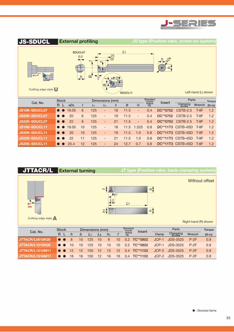
B 3˚
5f
0.0 2520
L1
b
h G
B
6f
h øDs
rε (N·m)R L øDs f L1 L2 h B G
JS19K-SDUCL07 � � 19.05 6 125 - 18 11.5 - 0.4 DC**0702 CSTB-2.5 T-8F 1.2
JS20K-SDUCL07 � � 20 6 125 - 19 11.5 - 0.4 DC**0702 CSTB-2.5 T-8F 1.2
JS22K-SDUCL07 � � 22 6 125 - 21 11.5 - 0.4 DC**0702 CSTB-2.5 T-8F 1.2
JS19K-SDUCL11 � � 19.05 10 125 - 18 11.5 1.525 0.8 DC**11T3 CSTB-4SD T-8F 1.2
JS20K-SDUCL11 � � 20 10 125 - 19 11.5 1.0 0.8 DC**11T3 CSTB-4SD T-8F 1.2
JS22K-SDUCL11 � � 22 11 125 - 21 11.5 1.0 0.8 DC**11T3 CSTB-4SD T-8F 1.2
JS25K-SDUCL11 � � 25.4 12 125 - 24 12.7 0.7 0.8 DC**11T3 CSTB-4SD T-8F 1.2
JS-SDUCL
SDUCL11
SDUCL07
rε (N·m)R L h b L1 L2 h1 fJTTACR/L0810K08 � � 8 10 125 10 8 10 0.2 TC**0802 JCP-1 JDS-3525 P-2F 0.9
JTTACR/L1010K08 � � 10 10 125 10 10 10 0.2 TC**0802 JCP-1 JDS-3525 P-2F 0.9
JTTACR/L1212M11 � � 12 12 150 12 12 12 0.4 TC**1102 JCP-2 JDS-3525 P-2F 0.9
JTTACR/L1616M11 � � 16 16 150 12 16 16 0.4 TC**1102 JCP-2 JDS-3525 P-2F 0.9
JTTACR/L
L1L2
bh
fh 1
91°
91°
External profi ling JS type (Positive rake, screw-on system)
Stock Dimensions (mm) Cat. No. Insert
Standardcornerradius
Parts Torque Clamping Wrench screw
Left-hand (L) shownCutting edge style U
External turning JT type (Positive rake, back-clamping system)
InsertStandard
cornerradius
Parts Clamp Clamping Wrench screw
Right-hand (R) shown
Without offset
Cutting edge style A
Cat. No.Dimensions (mm)Stock Torque
� : Stocked items
34
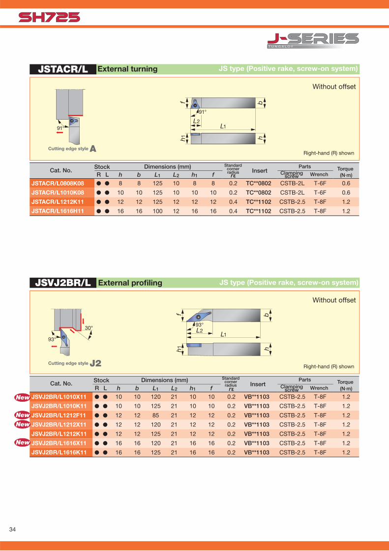
JSVJ2BR/L
h1 h
f b
L1L293°30°
93°
rε (N·m)R L h b L1 L2 h1 fJSVJ2BR/L1010X11 � � 10 10 120 21 10 10 0.2 VB**1103 CSTB-2.5 T-8F 1.2
JSVJ2BR/L1010K11 � � 10 10 125 21 10 10 0.2 VB**1103 CSTB-2.5 T-8F 1.2
JSVJ2BR/L1212F11 � � 12 12 85 21 12 12 0.2 VB**1103 CSTB-2.5 T-8F 1.2
JSVJ2BR/L1212X11 � � 12 12 120 21 12 12 0.2 VB**1103 CSTB-2.5 T-8F 1.2
JSVJ2BR/L1212K11 � � 12 12 125 21 12 12 0.2 VB**1103 CSTB-2.5 T-8F 1.2
JSVJ2BR/L1616X11 � � 16 16 120 21 16 16 0.2 VB**1103 CSTB-2.5 T-8F 1.2
JSVJ2BR/L1616K11 � � 16 16 125 21 16 16 0.2 VB**1103 CSTB-2.5 T-8F 1.2
JSTACR/L
h1 hbf
L1L291°
91°
rε (N·m)R L h b L1 L2 h1 fJSTACR/L0808K08 � � 8 8 125 10 8 8 0.2 TC**0802 CSTB-2L T-6F 0.6
JSTACR/L1010K08 � � 10 10 125 10 10 10 0.2 TC**0802 CSTB-2L T-6F 0.6
JSTACR/L1212K11 � � 12 12 125 12 12 12 0.4 TC**1102 CSTB-2.5 T-8F 1.2
JSTACR/L1616H11 � � 16 16 100 12 16 16 0.4 TC**1102 CSTB-2.5 T-8F 1.2
New
New
New
New
External profi ling JS type (Positive rake, screw-on system)
Without offset
Right-hand (R) shownCutting edge style J2
InsertStandard
cornerradius
Parts Torque Clamping Wrench screw
Cat. No. Dimensions (mm)Stock
Without offset
External turning JS type (Positive rake, screw-on system)
Right-hand (R) shownCutting edge style A
InsertStandard
cornerradius
Parts Torque Clamping Wrench screw
Cat. No.Dimensions (mm)Stock

35
JSVJBR/L
h1
L1
hbf
L293°
93°
rε (N·m)R L h b L1 L2 h1 fJSVJBR/L1010H11 � � 10 10 100 20 10 12 0.4 VB**1103 CSTB-2.5 T-8F 1.2
JSVJBR/L1212H11 � � 12 12 100 22 12 16 0.4 VB**1103 CSTB-2.5 T-8F 1.2
JSVJBR/L1616H11 � � 16 16 100 22 16 20 0.4 VB**1103 CSTB-2.5 T-8F 1.2
JSVJBR-F
rε (N·m)h b L1 L2 L3 L4 h1 f f1JSVJBR1216F11-F15 � 12 16 85 12.6 27 21 12 15 26 0.2 VB**1103** CSTB-2.5 T-8F 1.2JSVJBR1216X11-F15 � 12 16 120 12.6 27 21 12 15 26 0.2 VB**1103** CSTB-2.5 T-8F 1.2JSVJBR1620X11-F15 � 16 20 120 12.6 27 21 16 15 26 0.2 VB**1103** CSTB-2.5 T-8F 1.2
L1
bh
L4L2
93°
h1
L3
f1 f
93°50°
New
� : Stocked items
External profi ling JS type (Positive rake, screw-on system)
Right-hand (R) shownCutting edge style J
InsertStandard
cornerradius
Parts Torque Clamping Wrench screw
Cat. No.Dimensions (mm)Stock
Neck-down type (Positive rake, screw-on system)External turning and profi ling
Right-hand (R) shownCutting edge style J
InsertStandard
cornerradius
Parts Clamping Wrench screw
Cat. No.Dimensions (mm)
Stock Torque

36
JSVJ2BR/L
30°
93°
hb
L1L2
93°
h 1f 2
f
5/16”-24UNF
rεR L h b L1 L2 h1 f f2 (N·m)JSVJ2BR/L1212F11-CHP � � 12 12 85 23.6 12 12 14.7 0.2 VB**1103** CSTB-2.5 T-8F 1.2
JSVABR/L
f b
L1L291°
h1 h
91°
rε (N·m)R L h b L1 L2 h1 fJSVABR/L1010K11 � � 10 10 125 21 10 10 0.2 VB**1103 CSTB-2.5 T-8F 1.2JSVABR/L1212K11 � � 12 12 125 21 12 12 0.2 VB**1103 CSTB-2.5 T-8F 1.2JSVABR/L1616K11 � � 16 16 125 21 16 16 0.2 VB**1103 CSTB-2.5 T-8F 1.2
� : Stocked items★ : Available in 2015
Cutting edge style: J2
External turning and profi ling CHP type (Positive rake, screw-on system)
Right-hand (R) shown
Cat. NoStock Dimensions (mm) Std.
cornerradius Insert
PartsClamping
screw WrenchTorque
External turning JS type (Positive rake, screw-on system)
Right-hand (R) shownCutting edge style A
Without offset
InsertStandard
cornerradius
Parts Torque Clamping Wrench screw
Cat. No.Dimensions (mm)Stock
Without offset
Works with high-pressure coolant

37
JSVNBN
New
rε (N·m)h b L1 L2 h1 fJSVNBN1010X11 � 10 10 120 22 10 0 0.2 VB**1103 CSTB-2.5 T-8F 1.2
JSVNBN1212F11 � 12 12 85 22 12 0 0.2 VB**1103 CSTB-2.5 T-8F 1.2
JSVNBN1212X11 � 12 12 120 22 12 0 0.2 VB**1103 CSTB-2.5 T-8F 1.2
JSVNBN1616X11 � 16 16 120 22 16 0 0.2 VB**1103 CSTB-2.5 T-8F 1.2
L1L2
bh
fh1
72.5°72.5°
JSVL2PR/L
f b
L1L295°
h1 h
95°
rε (N·m)R L h b L1 L2 h1 fJSVL2PR/L1010X08 � � 10 10 120 16 10 10 0.2 VP**0802 CSTB-2L T-6F 0.6
JSVL2PR/L1010K08 � � 10 10 125 16 10 10 0.2 VP**0802 CSTB-2L T-6F 0.6
JSVL2PR/L1212F08 � � 12 12 85 16 12 12 0.2 VP**0802 CSTB-2L T-6F 0.6
JSVL2PR/L1212F11 � � 12 12 85 21 12 12 0.2 VP**1103 CSTB-2.5 T-8F 1.2
JSVL2PR/L1212X08 � � 12 12 120 16 12 12 0.2 VP**0802 CSTB-2L T-6F 0.6
JSVL2PR/L1212X11 � � 12 12 120 21 12 12 0.2 VP**1103 CSTB-2.5 T-8F 1.2
JSVL2PR/L1212K08 � � 12 12 125 16 12 12 0.2 VB**0802 CSTB-2L T-6F 0.6
JSVL2PR/L1616X08 � � 16 16 120 16 16 16 0.2 VP**0802 CSTB-2L T-6F 0.6
JSVL2PR/L1616K08 � � 16 16 125 16 16 16 0.2 VP**0802 CSTB-2L T-6F 0.6
JSVL2PR/L1616X11 � � 16 16 120 21 16 16 0.2 VP**1103 CSTB-2.5 T-8F 1.2
New
NewNewNewNew
New
New
� : Stocked items
External profi ling JS type (Positive rake, screw-on system)
Right-hand (R) shownCutting edge style N
InsertStandard
cornerradiusCat. No.
Dimensions (mm) PartsWrenchClamping
screwStock Torque
External turning and facing JS type (Positive rake, screw-on system)
Right-hand (R) shownCutting edge style L2
Without offset
InsertStandard
cornerradius
Parts Torque Clamping Wrench screw
Cat. No.Dimensions (mm)Stock

38
rε (N·m)h b L1 L2 h1 f f2JSVP2PR/L1010K08 l 10 10 125 16 10 10 4 0.2 VPoo0802 CSTB-2L T-6F 0.6JSVP2PR/L1212K08 l 12 12 125 16 12 12 2 0.2 VPoo0802 CSTB-2L T-6F 0.6JSVP2PR/L1616K08 l 16 16 125 16 16 16 2 0.2 VPoo0802 CSTB-2L T-6F 0.6JSVP2PR/L1010K11 l 10 10 125 20 10 10 8 0.2 VPoo1103 CSTB-2.5 T-8F 1.2JSVP2PR/L1212K11 l 12 12 125 20 12 12 6 0.2 VPoo1103 CSTB-2.5 T-8F 1.2JSVP2PR/L1616K11 l 16 16 125 20 16 16 6 0.2 VPoo1103 CSTB-2.5 T-8F 1.2
JSVP2P R/L
f b
L1
L2f 2
117.
5°
h 1 h
27.5°
rε (N·m)R L h b L1 L2 h1 f f2JSVP2PR/L1010K08 � � 10 10 125 16 10 10 4 0.2 VP**0802 CSTB-2L T-6F 0.6
JSVP2PR/L1212K08 � � 12 12 125 16 12 12 2 0.2 VP**0802 CSTB-2L T-6F 0.6
JSVP2PR/L1616K08 � � 16 16 125 16 16 16 2 0.2 VP**0802 CSTB-2L T-6F 0.6
JSVP2PR/L1010K11 � � 10 10 125 20 10 10 8 0.2 VP**1103 CSTB-2.5 T-8F 1.2
JSVP2PR/L1212K11 � � 12 12 125 20 12 12 6 0.2 VP**1103 CSTB-2.5 T-8F 1.2
JSVP2PR/L1616K11 � � 16 16 125 20 16 16 6 0.2 VP**1103 CSTB-2.5 T-8F 1.2
JSVP2PR/L
f b
L1L2
f2
117.5°
h1 h
27.5°
JTTANR/L
hbf
L2
L1
h1
91°
91˚
rε (N·m)R L h b L1 L2 h1 fJTTANR/L1216K16 � � 12 16 125 19.8 12 16 0.4 TN**1604 JCP-3N JDS-5040 P-2.5F 1.2
JTTANR/L1616K16 � � 16 16 125 19.8 16 16 0.4 TN**1604 JCP-3N JDS-5040 P-2.5F 1.2
� : Stocked items
Without offset
External profi ling and undercut JS type (Positive rake, screw-on system)
Stock Dimensions (mm) Cat. No. Insert
Standardcornerradius
Parts Torque Clamping Wrench screw
Right-hand (R) shownCutting edge style P2
External turning JT type (Negative rake, back-clamping system)
Without offset
Right-hand (R) shown
Cutting edge style A
InsertStandard
cornerradius
Parts Clamp Clamping Wrench screw
Cat. No.Dimensions (mm)Stock Torque

39
JTTLNR/L
95°
L1L2
fh 1
bh
95°New
rε (N·m)R L h b L1 L2 h1 fJTTLNR/L1216F16 � � 12 16 85 17 12 16 0.4 TN**1604** JCP-3N JDS-5040 P-2.5F 1.0
JTTLNR/L1216X16 � � 12 16 120 17 12 16 0.4 TN**1604** JCP-3N JDS-5040 P-2.5F 1.0
JTTLNR/L1616X16 � � 16 16 120 17 16 16 0.4 TN**1604** JCP-3N JDS-5040 P-2.5F 1.0
PTL2NR/L
rε (N·m)R L h b L1 L2 h1 f
PTL2NR/L2020H16 � � 20 20 100 22 20 20 0.4 TN**1604** LST317 LCS3 LCL3 LSP3 P-2.5 2.0
L1
fh1
bh
L295°
45°95°
New
External turning and facing
Right-hand (R) shownCutting edge style L
Without offset
JT type (Negative rake, back-clamping system)
� : Stocked items
InsertStandard
cornerradius
Parts Clamp Clamping Wrench screw
Cat. No.Dimensions (mm)Stock Torque
External turning and facing P type (Negative rake, lever-lock system)
Right-hand (R) shown
InsertStandard
cornerradius
Parts
Shim Clampingscrew Lever Spring Wrench
Cat. No.Stock Dimensions (mm)
Cutting edge style L2
Without offset
Torque

40
(N·m)R L h b L1 L2 h1 f C
JSTBR/L1010X3 � � 10 10 120 15 12 10 5 JTBR/L3** CSTB-4SD T-8F (T-8L) 1.2
JSTBR/L1010K3 � � 12 12 125 15 10 10 5 JTBR/L3** CSTB-4SD T-8F (T-8L) 1.2
JSTBR/L1212F3 � � 12 12 85 15 12 12 3 JTBR/L3** CSTB-4SD T-8F (T-8L) 1.2
JSTBR/L1212X3 � � 12 12 120 15 12 12 3 JTBR/L3** CSTB-4SD T-8F (T-8L) 1.2
JSTBR/L1212K3 � � 12 12 125 15 12 12 3 JTBR/L3** CSTB-4SD T-8F (T-8L) 1.2
JSTBR/L1616X3 � � 16 16 120 15 16 16 - JTBR/L3** CSTB-4SD T-8F (T-8L) 1.2
JSTBR/L1616K3 � � 16 16 125 15 16 16 - JTBR/L3** CSTB-4SD T-8F (T-8L) 1.2
JSTBR/L
New
New
New
New
L1L2
bh
fh1
C
JS-TBL3
B
0.0 2517
ø32
h
f
L1
b
h
øDs
(N·m)øDs f L1 L2 h B
JS19K-TBL3 � 19.05 6 125 - 18 11.5 JTBR3*** CSTB-4S T-15F 3.0
JS20K-TBL3 � 20 6 125 - 19 11.5 JTBR3*** CSTB-4S T-15F 3.0
JS22K-TBL3 � 22 6 125 - 21 11.5 JTBR3*** CSTB-4S T-15F 3.0
JS25K-TBL3 � 25.4 10 125 - 24 12.7 JTBR3*** CSTB-4S T-15F 3.0
� : Stocked items
Can be wrenched from the back side with double-socket torx screw.
Back turning
Cat. No.Stock Dimensions (mm)
Insert
JS type (Screw-on system)
Clamping screw
Right-hand (R) shown
Parts
ap ≤ 2.5 mm
Notes: Left-hand holder use right-hand insert.
Back turning JS type (Screw-on system)
Left-hand (L) shown
ap ≤ 2.5 mm
Torque
InsertCat. No.Dimensions (mm)Stock Torque
WrenchClamping screw
Parts
Wrench (Optional)

41
JSEGR/L
(N·m)R L h b L1 L2 h1 f
JSEGR/L1010K10 � � 10 10 125 3.3 10 7.5 J10ER/L***** CSTB-2.5 T-8F (T-8L) 1.2
JSEGR/L1212K10 � � 12 12 125 3.3 12 9.5 J10ER/L***** CSTB-2.5 T-8F (T-8L) 1.2
JSEGR/L1616K10 � � 16 16 125 3.3 16 13.5 J10ER/L***** CSTB-2.5 T-8F (T-8L) 1.2
L1
bfh1 h
L2
Back turning JS type (Screw-on system)
Right-hand (R) shown
ap ≤ 3 mm
Cat. No.Stock Dimensions (mm)
InsertClamping screw
Parts
� : Stocked items
TorqueWrench (Optional)

42
øDm rε (N·m)R L øDs f L1 L2 h f2 θ α
A04F-SCLCR/L03-D050 � � 5 4 2.5 80 8 3.8 - 0˚ -15˚ 0.2 CC**03X1 CSTA-1.6 T-6F 0.6
A05F-SCLCR/L03-D060 � � 6 5 3 80 9 4.8 - 0˚ -13˚ 0.2 CC**03X1 CSTA-1.6 T-6F 0.6
A06G-SCLCR/L04-D070 � � 7 6 3.5 90 11 5.75 - 0˚ -13˚ 0.2 CC**04T1 CSTB-2 T-6F 0.6
A07G-SCLCR/L04-D080 � � 8 7 4 90 12 6.75 - 0˚ -11˚ 0.2 CC**04T1 CSTB-2 T-6F 0.6
øDm rε (N·m)R L øDs f L1 L2 h f2 θ α
E04G-SCLCR/L03-D050 � � 5 4 2.5 90 9 3.8 - 0˚ -15˚ 0.2 CC**03X1 CSTA-1.6 T-6F 0.6
E05G-SCLCR/L03-D060 � � 6 5 3 90 10 4.8 - 0˚ -13˚ 0.2 CC**03X1 CSTA-1.6 T-6F 0.6
E06H-SCLCR/L04-D070 � � 7 6 3.5 100 12 5.75 - 0˚ -13˚ 0.2 CC**04T1 CSTB-2 T-6F 0.6
E07H-SCLCR/L04-D080 � � 8 7 4 100 14 6.75 - 0˚ -11˚ 0.2 CC**04T1 CSTB-2 T-6F 0.6
SCLCR/L
ØDm
α
95°
f
h
L1L2
θ
ØD
s
Boring & internal facing S type (Positive, screw-on)
When using a right or left-hand insert, the right-hand insert is used for the left-hand toolholder (SCLCL oo type), and the left-hand insert is used for the right-hand toolholder (SCLCRoo type).
■ Carbide shank
Parts Clamping Wrench screw
Stock Min Dimensions (mm) Cat. No. bore.dia. Insert
Std.cornerradius
Parts Clamping Wrench screw
Stock Min Dimensions (mm) Cat. No. bore.dia. Insert
Std.cornerradius
■ Steel shank
Torque
Torque
Right-hand (R) shownCutting edge style L
� : Stocked items
Oil Hole
43
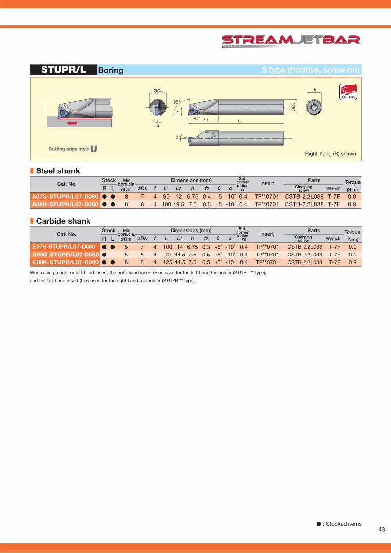
øDm rε (N·m)R L øDs f L1 L2 h f2 θ α
A07G-STUPR/L07-D080 � � 8 7 4 90 12 6.75 0.4 +5˚ -10˚ 0.4 TP**0701 CSTB-2.2L038 T-7F 0.9A08H-STUPR/L07-D080 � � 8 8 4 100 19.5 7.5 0.5 +5˚ -10˚ 0.4 TP**0701 CSTB-2.2L038 T-7F 0.9
øDm rε (N·m)R L øDs f L1 L2 h f2 θ α
E07H-STUPR/L07-D080 � � 8 7 4 100 14 6.75 0.3 +5˚ -10˚ 0.4 TP**0701 CSTB-2.2L038 T-7F 0.9E08G-STUPR/L07-D080 � 8 8 4 90 44.5 7.5 0.5 +5˚ -10˚ 0.4 TP**0701 CSTB-2.2L038 T-7F 0.9E08K-STUPR/L07-D080 � � 8 8 4 125 44.5 7.5 0.5 +5˚ -10˚ 0.4 TP**0701 CSTB-2.2L038 T-7F 0.9
STUPR/L
θ
ØDm
α
95°
f
L2f 2
L1
ØD
s
h
Boring S type (Positive, screw-on)
Parts Clamping Wrench screw
Stock Min Dimensions (mm) Cat. No. bore.dia. TorqueInsert
Std.cornerradius
When using a right or left-hand insert, the right-hand insert (R) is used for the left-hand toolholder (STUPL ** type),
and the left-hand insert (L) is used for the right-hand toolholder (STUPR ** type).
■ Carbide shank
■ Steel shank
Right-hand (R) shownCutting edge style U
Parts Clamping Wrench screw
Stock Min Dimensions (mm) Cat. No. bore.dia. TorqueInsert
Std.cornerradius
Oil Hole
� : Stocked items

44
øDm rε (N·m)R L øDs f L1 L2 h f2 θ α
*A05F-SWUBR/L03-D060 � � 6 5 3 80 9 4.8 - 0˚ -13˚ 0.4 WB**0301 CSTB-2 T-6F 0.6
*A06G-SWUBR/L03-D070 � � 7 6 3.5 90 11 5.75 - 0˚ -12˚ 0.4 WB**0301 CSTB-2 T-6F 0.6
*A07G-SWUBR/L03-D080 � � 8 7 4 90 12 6.75 - 0˚ -11˚ 0.4 WB**0301 CSTB-2 T-6F 0.6
A08H-SWUBR03-D060 � 6 8 3.1 100 18 7.5 - 0˚ -12˚ 0.4 WB**0301 CSTB-2 T-6F 0.6
A08H-SWUBR03-D070 � 7 8 3.6 100 20 7.5 - 0˚ -12˚ 0.4 WB**0301 CSTB-2 T-6F 0.6
øDm rε (N·m)R L øDs f L1 L2 h f2 θ α
*E05G-SWUBR/L03-D060 � � 6 5 3 90 10 4.8 - 0˚ -13˚ 0.4 WB**0301 CSTB-2 T-6F 0.6
*E06H-SWUBR/L03-D070 � � 7 6 3.5 100 12 5.75 - 0˚ -12˚ 0.4 WB**0301 CSTB-2 T-6F 0.6
*E07H-SWUBR/L03-D080 � � 8 7 4 100 14 6.75 - 0˚ -11˚ 0.4 WB**0301 CSTB-2 T-6F 0.6
E08K-SWUBR03-D060 � 6 8 3.1 125 30 7.5 - 0˚ -12˚ 0.4 WB**0301 CSTB-2 T-6F 0.6
E08K-SWUBR03-D070 � 7 8 3.6 125 40 7.5 - 0˚ -12˚ 0.4 WB**0301 CSTB-2 T-6F 0.6
SWUBR/L
93°
f
L
ØD
s
1
h
ØD
s
ØDm
f
93°
αL2
θ
L1
� : Stocked in Japan
Boring S type (Positive, screw-on)
Parts Clamping Wrench screw
Stock Min Dimensions (mm) Cat. No. bore.dia. Insert
Std.cornerradius
Parts Clamping Wrench screw
Stock Min Dimensions (mm) Cat. No. bore.dia. Insert
Std.cornerradius
When using a right or left-hand insert, the right-hand insert (R) is used for the left-hand toolholder (SWUBL oo type), and the left-hand insert (L) is used for the right-hand toolholder (SWUBR ootype).
Torque
Torque
■ Carbide shank
■ Steel shank
Right-hand (R) shownCutting edge style U
*Straight shank style
Oil Hole
45
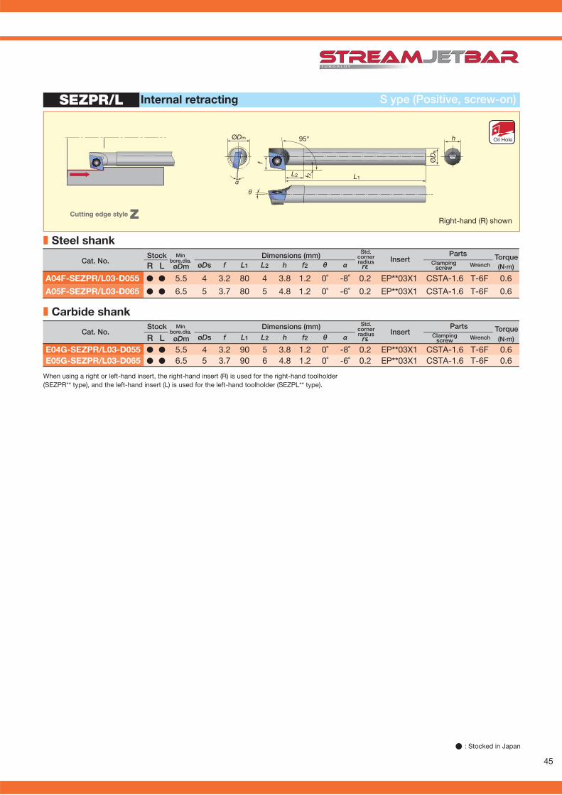
øDm rε (N·m)R L øDs f L1 L2 h f2 θ α
A04F-SEZPR/L03-D055 � � 5.5 4 3.2 80 4 3.8 1.2 0˚ -8˚ 0.2 EP**03X1 CSTA-1.6 T-6F 0.6
A05F-SEZPR/L03-D065 � � 6.5 5 3.7 80 5 4.8 1.2 0˚ -6˚ 0.2 EP**03X1 CSTA-1.6 T-6F 0.6
øDm rε (N·m)R L øDs f L1 L2 h f2 θ α
E04G-SEZPR/L03-D055 � � 5.5 4 3.2 90 5 3.8 1.2 0˚ -8˚ 0.2 EP**03X1 CSTA-1.6 T-6F 0.6E05G-SEZPR/L03-D065 � � 6.5 5 3.7 90 6 4.8 1.2 0˚ -6˚ 0.2 EP**03X1 CSTA-1.6 T-6F 0.6
SEZPR/L
95°
f
L2 f 2 L1
ØD
s
ØDm h
θα
Parts Clamping Wrench screw
Stock Min Dimensions (mm) Cat. No. bore.dia.
Std.cornerradius
Parts Clamping Wrench screw
Stock Min Dimensions (mm) Cat. No. bore.dia.
Std.cornerradius
S ype (Positive, screw-on)Internal retracting
Insert
Insert
When using a right or left-hand insert, the right-hand insert (R) is used for the right-hand toolholder (SEZPR** type), and the left-hand insert (L) is used for the left-hand toolholder (SEZPL** type).
Torque
Torque
■ Carbide shank
■ Steel shank
Right-hand (R) shownCutting edge style Z
Oil Hole
� : Stocked in Japan
46
øDm rε (N·m)R L øDs f L1 L2 h f2 θ α
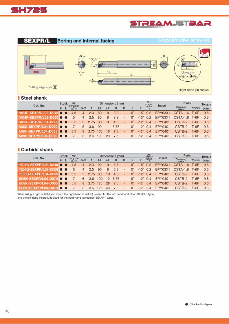
*A04F-SEXPR/L03-D045 � � 4.5 4 2.3 80 8 3.8 - 0˚ -15˚ 0.2 EP**03X1 CSTA-1.6 T-6F 0.6*A04F-SEXPR/L03-D050 � � 5 4 2.5 80 8 3.8 - 0˚ -13˚ 0.2 EP**03X1 CSTA-1.6 T-6F 0.6*A05F-SEXPR/L04-D055 � � 5.5 5 2.75 80 9 4.8 - 0˚ -12˚ 0.4 EP**0401 CSTB-2 T-6F 0.6A06G-SEXPR/L04-D070 � � 7 6 3.6 90 11 5.75 - 0˚ -12˚ 0.4 EP**0401 CSTB-2 T-6F 0.6A08H-SEXPR/L04-D055 � � 5.5 8 2.75 100 16 7.5 - 0˚ -12˚ 0.4 EP**0401 CSTB-2 T-6F 0.6A08H-SEXPR/L04-D070 � � 7 8 3.6 100 20 7.5 - 0˚ -12˚ 0.4 EP**0401 CSTB-2 T-6F 0.6
øDm rε (N·m)R L øDs f L1 L2 h f2 θ α
*E04G-SEXPR/L03-D045 � � 4.5 4 2.3 90 9 3.8 - 0˚ -15˚ 0.2 EP**03X1 CSTA-1.6 T-6F 0.6*E04G-SEXPR/L03-D050 � � 5 4 2.5 90 9 3.8 - 0˚ -13˚ 0.2 EP**03X1 CSTA-1.6 T-6F 0.6*E05G-SEXPR/L04-D055 � � 5.5 5 2.75 90 10 4.8 - 0˚ -12˚ 0.4 EP**0401 CSTB-2 T-6F 0.6E06H-SEXPR/L04-D070 � � 7 6 3.6 100 12 5.75 - 0˚ -12˚ 0.4 EP**0401 CSTB-2 T-6F 0.6E08K-SEXPR/L04-D055 � � 5.5 8 2.75 125 28 7.5 - 0˚ -12˚ 0.4 EP**0401 CSTB-2 T-6F 0.6E08K-SEXPR/L04-D070 � � 7 8 3.6 125 40 7.5 - 0˚ -12˚ 0.4 EP**0401 CSTB-2 T-6F 0.6
SEXPR/L
100°
f
L1
ØD
s
θ
ØDm
α
100°
f
L1
ØD
s
h
L2
� : Stocked in Japan
Parts Clamping Wrench screw
Stock Min Dimensions (mm) Cat. No. bore.dia. Insert
Std.cornerradius
Parts Clamping Wrench screw
Stock Min Dimensions (mm) Cat. No. bore.dia. Insert
Std.cornerradius
S type (Positive, screw-on)Boring and internal facing
When using a right or left-hand insert, the right-hand insert (R) is used for the left-hand toolholder (SEXPL** type), and the left-hand insert (L) is used for the right-hand toolholder (SEXPR** type).
Torque
Torque
■ Carbide shank
■ Steel shank
Right-hand (R) shownCutting edge style X
*Straight shank style
Oil Hole

47
JSVGR/L
L1
fh1
bh
6.2
L2
35°
(N·m)R L h b L1 L2 h1 f
JSVGR/L1010K-C � � 10 10 125 23 10 10 JVGR/L***(F) CSTB-3S T-9F (T-9L) 2.3
JSVGR/L1212K-C � � 12 12 125 23 12 12 JVGR/L***(F) CSTB-3S T-9F (T-9L) 2.3
JSVGR/L1616K � � 16 16 125 23 16 16 JVGR/L***(F) CSTB-3S T-9F (T-9L) 2.3
(N·m)R L h b L1 L2 h1 f C
JSTGR/L1010X3 � � 10 10 120 18.5 12 10 2 JTGR/L3** CSTB-4SD T-8F (T-8L) 1.2
JSTGR/L1010K3 � � 12 12 125 18.5 10 10 2 JTGR/L3** CSTB-4SD T-8F (T-8L) 1.2
JSTGR/L1212F3 � � 12 12 85 18.5 12 12 - JTGR/L3** CSTB-4SD T-8F (T-8L) 1.2
JSTGR/L1212X3 � � 12 12 120 18.5 12 12 - JTGR/L3** CSTB-4SD T-8F (T-8L) 1.2
JSTGR/L1212K3 � � 12 12 125 18.5 12 12 - JTGR/L3** CSTB-4SD T-8F (T-8L) 1.2
JSTGR/L1616X3 � � 16 16 120 18.5 16 16 - JTGR/L3** CSTB-4SD T-8F (T-8L) 1.2
JSTGR/L1616K3 � � 16 16 125 18.5 16 16 - JTGR/L3** CSTB-4SD T-8F (T-8L) 1.2
JSTGR/L
L1L2
bhh1
f
C
New
New
New
New
(Two corner type)
External grooving JS type (Screw-on system)
Right-hand (R) shown
C-type
Wrench (Optional)Clamping screw
Parts
Grooving toolholders
Cat. No.Stock Dimensions (mm)
Insert Torque
Wrench (Optional)Clamping screw
PartsCat. No.
Stock Dimensions (mm)Insert Torque
� : Stocked items
Can be wrenched from the back side with double-socket Torx screw.
External grooving JS type (Screw-on system)
Right-hand (R) shown

48
(N·m)R L h b L1 L2 h1 f C
JSTTR/L1010X3 � � 10 10 120 18.5 12 10 2 JTTR/L3** CSTB-4SD T-8F (T-8L) 1.2
JSTTR/L1010K3 � � 12 12 125 18.5 10 10 2 JTTR/L3** CSTB-4SD T-8F (T-8L) 1.2
JSTTR/L1212F3 � � 12 12 85 18.5 12 12 - JTTR/L3** CSTB-4SD T-8F (T-8L) 1.2
JSTTR/L1212X3 � � 12 12 120 18.5 12 12 - JTTR/L3** CSTB-4SD T-8F (T-8L) 1.2
JSTTR/L1212K3 � � 12 12 125 18.5 12 12 - JTTR/L3** CSTB-4SD T-8F (T-8L) 1.2
JSTTR/L1616X3 � � 16 16 120 18.5 16 16 - JTTR/L3** CSTB-4SD T-8F (T-8L) 1.2
JSTTR/L1616K3 � � 16 16 125 18.5 16 16 - JTTR/L3** CSTB-4SD T-8F (T-8L) 1.2
JSTTR
L1
L2
bh
fh1
C
5˚
New
New
New
New
JS-TGL3
h L1
fB
20
b
h øDs
(N·m)øDs f L1 L2 h/b BJS19K-TGL3 � 19.05 6 125 - 18 11.5 JTGR3*** (F) CSTB-4S T-15F 3.0
JS20K-TGL3 � 20 6 125 - 19 11.5 JTGR3*** (F) CSTB-4S T-15F 3.0
JS22K-TGL3 � 22 6 125 - 21 11.5 JTGR3*** (F) CSTB-4S T-15F 3.0
JS25K-TGL3 � 25.4 10 125 - 24 12.7 JTGR3*** (F) CSTB-4S T-15F 3.0
External threading JS type (Screw-on system)
Right-hand (R) shownCan be wrenched from the back side with double-socket Torx screw.
� : Stocked items
Threading
Wrench (Optional)Clamping screw
PartsCat. No.
Stock Dimensions (mm)Insert Torque
External grooving JS type (Screw-on system)
Left-hand (L) shown
InsertCat. No.Dimensions (mm)Stock Torque
WrenchClamping screw
Parts

49
(N·m)øDs f L1 h/b B
JS19K-TTL3 � 19.05 10 125 18 11.5 JTTR30**F CSTB-4S T-15F 3.5
JS20K-TTL3 � 20 10 125 19 11.5 JTTR30**F CSTB-4S T-15F 3.5
JS22K-TTL3 � 22 10 125 21 11.5 JTTR30**F CSTB-4S T-15F 3.5
JS25K-TTL3 � 25.4 10 125 24 12.7 JTTR30**F CSTB-4S T-15F 3.5
JS-TTL3
L1
90°
øDm
h
fB
b
h øDs
JSDJ2XR/L1212F07-CHPDXGU0703��L/R
SR34-514 T-7F S-CU-CHP
JSWL2XR/L1212F04-CHPWXGU0403��L/R
SR34-514 T-7F S-CU-CHP
JSVJ2XR/L1212F09-CHPVB��1103��
SR34-508 T-7F S-CU-CHP
JSDJ2CR/L1212F07-CHPDC��0702��
CSTB-2.5 T-8F S-CU-CHP
JSDJ2CR/L1212F11-CHPDC��11T3��
CSTB-4SD T-8F S-CU-CHP
JSVJ2BR/L1212F11-CHPVB��1103��
CSTB-2.5 T-8F S-CU-CHP
External threading
Cat. No. StockDimensions (mm)
InsertWrench
JS-type (Screw-on system)
Clamping screw
Right-hand (R) shown
PartsTorque
Toolholder Cat. No Applicable inserts
Screw Wrench Coolant unit
Spare parts for TungJet toolholders
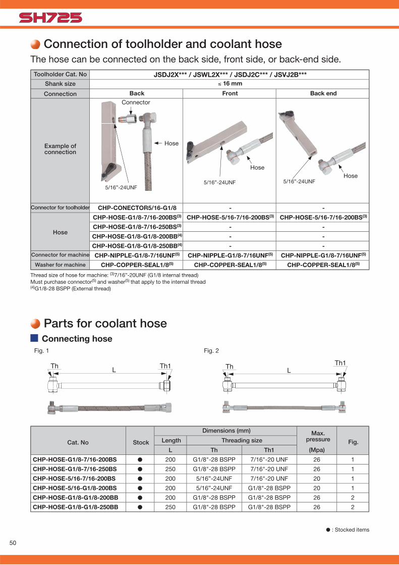
50
(Mpa)L Th Th1
CHP-HOSE-G1/8-7/16-200BS � 200 G1/8"-28 BSPP 7/16"-20 UNF 26 1
CHP-HOSE-G1/8-7/16-250BS � 250 G1/8"-28 BSPP 7/16"-20 UNF 26 1
CHP-HOSE-5/16-7/16-200BS � 200 5/16”-24UNF 7/16"-20 UNF 20 1
CHP-HOSE-5/16-G1/8-200BS � 200 5/16”-24UNF G1/8"-28 BSPP 20 1
CHP-HOSE-G1/8-G1/8-200BB � 200 G1/8"-28 BSPP G1/8"-28 BSPP 26 2
CHP-HOSE-G1/8-G1/8-250BB � 250 G1/8"-28 BSPP G1/8"-28 BSPP 26 2
JSDJ2X*** / JSWL2X*** / JSDJ2C*** / JSVJ2B***
CHP-CONECTOR5/16-G1/8 - -
CHP-HOSE-G1/8-7/16-200BS(3) CHP-HOSE-5/16-7/16-200BS(3) CHP-HOSE-5/16-7/16-200BS(3)
CHP-HOSE-G1/8-7/16-250BS(3) - -
CHP-HOSE-G1/8-G1/8-200BB(4) - -
CHP-HOSE-G1/8-G1/8-250BB(4) - -
CHP-NIPPLE-G1/8-7/16UNF(5) CHP-NIPPLE-G1/8-7/16UNF(5) CHP-NIPPLE-G1/8-7/16UNF(5)
CHP-COPPER-SEAL1/8(5) CHP-COPPER-SEAL1/8(5) CHP-COPPER-SEAL1/8(5)
5/16”-24UNF 5/16”-24UNF 5/16”-24UNF
� : Stocked items
Cat. No
Dimensions (mm)
Threading sizeLength Fig.Max.
pressureStock
Fig. 1 Fig. 2
Connecting hose
Parts for coolant hose
Back
≤ 16 mm
Front Back end
Toolholder Cat. No
Shank size
Connection
Example of connection
Washer for machine
Hose
Connector for toolholder
Connector for machine
Connector
Hose
HoseHose
Thread size of hose for machine: (3)7/16”-20UNF (G1/8 internal thread) Must purchase connector(5) and washer(5) that apply to the internal thread(4)G1/8-28 BSPP (External thread)
Connection of toolholder and coolant hoseThe hose can be connected on the back side, front side, or back-end side.

51
JSEGR1212K10 SVLPR1212X-11FFJ10ER010BF VPET110301MFR-JRP
SH725 SH725
100 1500.04 0.021.2 0.5
10000
7500
5000
2500
0
35 mm
ø6
20 mm
ø7
150
112.5
75
37.5
0
CHP-NIPPLE-G1/8-7/16UNF � øD ød W
CHP-COPPER-SEAL1/8 � 15 10 1
CHP-COPPER-SEAL5/16 � 11 8 1
CHP-COPPER-SEAL5/16-2.5 � 11 8 2.5
CHP-CONECTOR/5/16-G1/8 �
Workpiece typeToolholder
InsertGrade
Workpiece material
Cutting speed : Vc (m/min) Feed : f (mm/rev) Depth of cut : ap (mm) Machining Coolant
Results
Cut
ting
cond
ition
s
Shaft Shaft
SUM24L / Low-carbon free-cutting steel SCM415 / 18CrMo4
Back TurningWet
Insert in SH725 grade maintains accuracy in machined dimensions and extends tool life by 2 times even in back turning due to excellent wear and chipping resistance. Competitor
Tool life 200%UP!
Num
ber
of p
ices
wor
k (p
cs /
cor
ner)
External turning Wet
Practical examples
CompetitorNum
ber
of p
ices
wor
k (p
cs /
cor
ner)
Tool life 130% UP!
SH725 extends tool life by 130% and reduces fl ank wear due to improved wear resistance.
Cat. NoCat. No
Cat. No
Dimensions (mm)Stock
Stock
Stock
Connector
Connector for small lathewith seal washer
Seal washer
� : Stocked items

www.youtube.com/tungaloycorporation
Distributed by:
Sep. 2015 (TJ)Produced from Recycled paper
To see this product in action visit:w w w . t u n g a l o y . c o m
f a c e b o o k . c o m / t u n g a l o y j a p a nt w i t t e r . c o m / t u n g a l o y j a p a n
follow us at:
D O W N L O A D
Dr. Carbide App ISO 9001 Certifi edQC00J0056Tungaloy Corporation18/10/1996
ISO 14001 Certifi edEC97J1123Tungaloy GroupJapan site and Asianproduction site26/11/1997
Tungaloy Scandinavia ABS:t Lars Väg 42ASE-22270 Lund, SwedenPhone: +46-462119200 Fax: +46-462119207www.tungaloy.se
Tungaloy Rus, LLC36-D Harkovsky Lane308009 Belgorod, RussiaPhone: +7 4722 24 00 07 Fax: +7 4722 24 00 08www.tungaloy.co.jp/ru
Tungaloy Polska Sp. z o.o.ul. Genewska 24 03-963 Warszawa, PolandPhone: +48-22-617-0890 Fax: +48-22-617-0890www.tungaloy.co.jp/pl
Tungaloy U.K. LtdThe Technology Centre, Wolverhampton Science Park Glaisher Drive, WolverhamptonWest Midlands WV10 9RU, UKPhone: +44 121 4000 231 Fax: +44 121 270 9694 www.tungaloy.co.jp/uk [email protected]
Tungaloy Hungary KftErzsébet királyné útja 125 H-1142 Budapest, Hungary Phone: +36 1 781-6846 Fax: +36 1 781-6866www.tungaloy.co.jp/hu [email protected]
Tungaloy TurkeyDudullu OSB 4. Cad No:4 34776 Ümraniye Istanbul, TURKEY Phone: +90 216 540 04 67 Fax: +90 216 540 04 87www.tungaloy.com.tr [email protected]
Tungaloy Benelux b.v.Tjalk 70NL-2411 NZ Bodegraven, Netherlands Phone: +31 172 630 420 Fax: +31 172 630 429www.tungaloy-benelux.com
Tungaloy CroatiaJosipa Kozarca 410432 Bregana, Croatia Phone: +385 1 3326 604 Fax: +385 1 3327 683www.tungaloy.hr
Tungaloy Cutting Tool (Shanghai) Co.,Ltd.Rm No 401 No.88 Zhabei Jiangchang No.3 RdShanghai 200436, ChinaPhone: +86-21-3632-1880 Fax: +86-21-3621-1918www.tungaloy.co.jp/tcts
Tungaloy Cutting Tool (Thailand) Co.,Ltd.TCIF Tower 4th Fl. 1858/5-7 Bangna-Trad Road km.5 Bangna, Bangna, Bangkok 10260ThailandPhone: +66-2-751-5711 Fax: +66-2-751-5715www.tungaloy.co.th
Tungaloy Singapore (Pte.), Ltd.62 Ubi Road 1, #06-11 Oxley BizHub 2Singapore 408734Phone: +65-6391-1833 Fax: +65-6299-4557www.tungaloy.co.jp/tspl
Tungaloy Vietnam Unit 18, 4th Fl. Saigon Centre Building 65 Le Loi Blvd. Dist 1, Ho Chi Minh City, Vietnam Phone: +84-8-3827-0201 Fax: +84-8-3827-0203 www.tungaloy.co.jp/tspl
Tungaloy India Pvt. Ltd.Unit#13, B wing, 8th Fl.Kamala Mills Compound Trade World, Lower Parel (West)Mumbai - 4000 13. IndiaPhone: +91-22-6124-8804 Fax: +91-22-6124-8899www.tungaloy.co.jp/in
Tungaloy Korea Co., Ltd#1312, Byucksan Digital Valley 5-chaBeotkkot-ro 244, Geumcheon-gu153-788 Seoul, KoreaPhone: +82-2-2621-6161 Fax: +82-2-6393-8952www.tungaloy.co.jp/kr
Tungaloy Malaysia Sdn Bhd50 K-2, Kelana Mall, Jalan SS6/14Kelana Jaya, 47301 Petaling Jaya, Selangor Darul Ehsan MalaysiaPhone: +603-7805-3222 Fax: +603-7804-8563www.tungaloy.co.jp/my
Tungaloy Australia Pty LtdPO Box 2232, Rowville, Victoria 3178, AustraliaPhone: +61-3-9755-8147 Fax: +61-3-9755-6070www.tungaloy.com.au
PT. Tungaloy IndonesiaKompleks Grand Wisata Block AA-10 No.3-5 Cibitung Bekasi 17510, IndonesiaPhone: +62-21-8261-5808 Fax: +62-21-8261-5809www.tungaloy.co.jp/id
Tungaloy Corporation (Head offi ce)11-1 Yoshima-KogyodanchiIwaki-city, Fukushima, 970-1144 JapanPhone: +81-246-36-8501 Fax: +81-246-36-8542www.tungaloy.co.jp
Tungaloy America, Inc.3726 N Ventura DriveArlington Heights,IL 60004, U.S.A.Phone: +1-888-554-8394 Fax: +1-888-554-8392www.tungaloyamerica.com
Tungaloy Canada 432 Elgin St. Unit 3 Brantford, Ontario N3S 7P7, Canada Phone: +1-519-758-5779 Fax: +1-519-758-5791 www.tungaloy.co.jp/ca
Tungaloy de Mexico S.A.C Los Arellano 113, Parque Industrial Siglo XXIAguascalientes, AGS, Mexico 20290Phone: +52-449-929-5410 Fax: +52-449-929-5411www.tungaloy.co.jp/mx
Tungaloy do Brasil Ltda.Rua dos Sabias N.10413280-000 Vinhedo, São Paulo, BrazilPhone: +55-19-38262757 Fax: +55-19-38262757www.tungaloy.com/br
Tungaloy Germany GmbHAn der Alten Ziegelei 1D-40789 Monheim, GermanyPhone: +49-2173-90420-0 Fax: +49-2173-90420-19www.tungaloy.de
Tungaloy France S.A.S.ZA Courtaboeuf - Le Rio1 rue de la Terre de feuF-91952 Courtaboeuf Cedex, FrancePhone: +33-1-6486-4300 Fax: +33-1-6907-7817www.tungaloy.fr
Tungaloy Italia S.r.I.Via E. Andolfato 10I-20126 Milano, ItalyPhone: +39-02-252012-1 Fax: +39-02-252012-65www.tungaloy.it
Tungaloy Czech s.r.o.Turanka 115CZ-627 00 Brno, Czech RepublicPhone: +420-532 123 391 Fax: +420-532 123 392www.tungaloy.cz
Tungaloy Ibérica S.L.C/Miquel Servet, 43B, Nau 7 Pol. Ind. BufalventES-08243 Manresa (BCN), SpainPhone: +34 93 113 1360 Fax: +34 93 876 2798www.tungaloy.es