tunelovÉ stavby pro dokonČenÍ … · the package of structures of the city circle road being...
TRANSCRIPT

17
20. ročník - č. 2/2011
1 INRODUCTION
The package of structures of the City Circle Road being currentlyunder construction within the section between Malovanka and PelcTyrolka, containing the Blanka complex of tunnels (for more detailssee TUNEL 03/2007) will continue by the last section of the CityCircle Road (CCR) being under preparation, containing several othertunnel structures. From a formal point of view, it is a package of theCity Circle Road lots No. 0081 (Pelc Tyrolka – Balabenka section),
No. 0094 (Balabenka-Štěr-boholy Radial Road) and theLibeň Link Road (LLR),construction lot No. 8313,which, when completed, willmean the total completion ofthe inner ring road in Prague(see Fig. 1). According to theassumption formed in thevalid Master Plan for theCity of 1999 and, at the sametime, according to the con-cept dated 2009, the above-mentioned three constructionlots, found in the north-eas-tern segment of Prague, areparts of the high level systemof main roads.
When completed, the pac-kage of constructions (CCR+LLR) will offer a new alter -native route (e.g. an alternati-ve differing from the North-
South Backbone Road), allowing more fluent and quicker connectionwithin the city, not only from the north to the south but also in the oppo-site direction. But, first of all, it will offer a safer route, more considera-te of the living environment than the existing congested street network.After the completion, the entire City Circle Road, which is part of theradial-circular system, will provide a route bypassing the wider city cent-re, thus it will be possible to significantly restrict the transit traffic in thecentre and to prefer mass transport, including passenger and cycling traf-fic, and to start to deal with the active regulation of dispensable car traf-fic. The remaining parts of the CCR and LLR are 8.8 km and 1.4 kmlong respectively (see Fig. 2). Of this length, over 5 km are expected torun through mined or cut-and-cover / cover-and-cut tunnels.
2 BASIC DESCRIPTION
The routes for at-grade capacity roads approximately followingthe corridors of the constructions described in this paper were con-sidered even in the traffic management scheme contained in theconcept of the Basic road system in Prague (the so-called ZÁKOS),which was approved at the end of 1974. Some of the corridors havebeen designed for the transportation use for a significantly longertime, even since the period when proposals for the traffic system inPrague were dealt with during the so-called First Republic and sincethe 1950s and 1960s (general extension plans and zone planningdocuments).
1 ÚVOD
Na právě realizovaný soubor staveb Městského okruhu (MO) v úsekuMalovanka – Pelc-Tyrolka s tunelovým komplexem Blanka (podrobně-ji viz Tunel 03/2007) navazuje poslední připravovaná část Městskéhookruhu s několika dalšími tunelovými stavbami. Z hlediska formálníhojde o soubor staveb Městského okruhu č. 0081 (úsek Pelc-Tyrolka –Balabenka), č. 0094 (úsek Balabenka – Štěrboholská radiála)a Libeňskou spojku (LS) č. 8313, jejichž realizací dojde ke kompletní-mu dokončení vnitřního praž-ského okruhu (obr. 1). Podlepředpokladu platného územ-ního plánu hl. m. Prahyz roku 1999 a zároveň i podlekonceptu z roku 2009 jsoutyto tři stavby v seve ro vý -chod ním seg mentu měs ta sou-částí nadřazeného sys témuhlavních komunikací.
Po svém dokončení nabíd-ne soubor staveb MO+LSnovou alternativní trasu(například oproti Severojižnímagistrále) s nabídkou ply-nulejšího a rychlejšího spoje-ní městem, nejen ve směrusever–jih a naopak. Pře de -vším pak ale nabídne trasubezpečnější a ohle duplnějšík životnímu prostředí než jestávající přetížená uliční síť.Celý dokončený Městskýokruh jakožto součást radiálně-okružního systému zajistí objízdnoukomunikaci širšího centra města, takže bude možné významně ome-zit průjezdnou dopravu centrem, preferovat hromadnou dopravu,včetně dopravy pěší a cyklistické, a přistoupit k aktivní regulaci proměsto zbytné individuální automobilové dopravy. Délka zbývajícípřipravované části MO je 8,8 km, délka Libeňské spojky je 1,4 km(obr. 2). Z této délky je předpokládáno vedení trasy v raženýcha hloubených tunelech v celkové délce přes 5 km.
2 ZÁKLADNÍ POPIS
S vedením povrchových kapacitních komunikací přibližněv koridorech zde popisovaných staveb uvažovalo již dopravní řešeníobsažené v koncepci Základního komunikačního systému v Praze(tzv. ZÁKOS) schválené na konci roku 1974. Některé koridory jsoudokonce určeny pro dopravní využití výrazně déle, ještě z obdobínávrhů dopravního řešení Prahy z první republiky a 50.–60. let(směrné a regulační plány).
Stopa komunikací ze ZÁKOS byla víceméně převzata do dnesplatného územního plánu z roku 1999. Ovšem oproti ZÁKOS bylzpůsob vedení tras v územním plánu optimalizován tak, aby ko -munikace procházely územím s větším ohledem na okolní životníprostředí (obr. 3 a 4). Navržené řešení celého souboru staveb stu-dijně zpracované společnostmi Satra a Mott MacDonald Praha ještěvýrazněji rozvinulo tento požadavek zakomponováním řady opat-ření, zejména rozsáhlejšího využití tunelových úseků (hloubených
TUNELOVÉ STAVBY PRO DOKONČENÍ MĚSTSKÉHO OKRUHU V PRAZE TUNNEL STRUCTURES FOR COMPLETING THE CITY CIRCLE ROAD
IN PRAGUE
PAVEL ŠOUREK
Obr. 1 Schéma sítě hlavních komunikací v PrazeFig. 1 Layout of the network of main roads in Prague
Městský okruh (MO)City Circle Road (CCR)
Silniční okruh (SOKP) City Ring Road (CRR)
tunel_2_11:tunel_3_06 20.6.2011 20:06 Stránka 17

18
20. ročník - č. 2/2011
The footprint of theroads contained in theZÁKOS was more or lesstaken over and incorpora-ted into the plan from1999, which has been validtill now. Of course, theroutes were optimised inthe land use plan comparedwith the ZÁKOS, with theaim of increasing the res-pect to the surroundingliving environment whenpassing through the areas(see Figures 3 and 4). Thesolution for the entire pac-kage of construction lotswhich was proposed at thelevel of studies by SATRAa.s. and Mott MacDonaldPraha s. r. o. developed thisrequirement even toa higher level by incorpo-rating a range of measuresinto the solution, first of alla more extensive use oftunnels (both mined and
cut-and-cover / cover-and-cut) to follow modern trends in otherdeveloped countries in Europe (see Fig. 5). The protection of theliving environment and the historic urban structure of the city,together with the consideration of traffic states and services in thearea during the course of construction, has become one of thedesign priorities.
It is crucial for all of the three projects being solved that they arebrought into service jointly. For that reason the projects are consi-dered as a single package of constructions in terms of the stages ofplanning, implementation and opening to traffic. Without puttingthem into operation jointly, significant capacity-related problemswould originate within the linking area or the anticipated efficien-cy of the constructions being operated and the whole system of thehigh-level roads would be significantly reduced. As a result, theeconomic and ecological effectiveness of the solution being pro-posed would be devalued.
As far as the time is concerned, all of the constructions were con-sidered in the land use plan to be implemented in the horizon of2010. However, it is today obvious that the structures will not beopened to traffic in this term; the term after 2015 at the earliest,
i ražených) v souladu s moderními trendy v ostatních rozvinutýchzemích Evropy (obr. 5). Ochrana životního prostředí a historickéurbanistické struktury města se stala jednou z prvořadých prioritnávrhu, spolu se zohledněním dopravních stavů a obsluhy územív průběhu výstavby.
Pro všechny tři řešené stavby je rozhodující nutnost společnéhozprovoznění, proto jsou stavby pro etapy přípravy, realizacea zprovoznění uvažovány jako jeden soubor staveb. Bez společnéhozprovoznění by došlo k výrazným kapacitním problémům v sou -visejícím území, resp. k výraznému snížení očekávané účinnostiprovozovaných staveb a celého systému nadřazených komunikací.Tím by byla znehodnocena ekonomická a ekologická efektivitanavrhovaného řešení.
Z časového hlediska byly všechny stavby v územním plánu uva-žovány v horizontu do roku 2010. Dnes je však zřejmé, že ke zpro-voznění v tomto termínu nedojde a jako reálný časový horizont lzei s ohledem na potřebnou dobu výstavby a projektové přípravypředpokládat nejdříve období až po roce 2015 návazně na dokon-čení a zprovoznění severozápadní části MO s tunelovým komple-xem Blanka. Všechny tři stavby jsou rozhodnutím zastupitelstva
Obr. 2 Celková situace souboru staveb Městského okruhu a Libeňské spojkyFig. 2 General layout of the package of structures of the City Circle Road and the Libeň Link Road
Obr. 3 Křižovatka U Kříže – nedokončené části MOFig. 3 U Kříže intersection – the CCR parts to be completed
Obr. 4 Zenklova ulice – současnostFig. 4 Zenklova Street – current state
tunel_2_11:tunel_3_06 20.6.2011 20:06 Stránka 18
19
20. ročník - č. 2/2011
after the completion and inauguration of the north-western part ofthe CCR containing the Blanka complex of tunnels, appears to berealistic, even with respect to the time required for the constructi-on and design preparation. All of the three projects are listed accor-ding to a decision of the municipality as publicly beneficial, as arethe other projects forming the high-level traffic system in the Cityof Prague.
From the technical point of view, the design has been carried outin compliance with applicable standards and regulations; the cur-rent CSN 73 7507 standard in the case of designing tunnel structu-res. At the same time, the experience gained from other similarconstruction projects, designed and implemented not only in theconditions of the Czech Republic, is used, probably most of all theexperience from the planning and implementation of the Blankacomplex of tunnels in Prague. At last but not least, even new requ-irements of the future administrator, Technical Administration ofRoads of the City of Prague, have been incorporated.
The basic configuration within the entire package of structuresbeing designed corresponds to the customs existing on the opera-ting part of the City Circle Road. The roadway for the CCR andLLR is designed as a function class B of a local distributor road, inthe basic configuration comprising 2x2 transit traffic lanes 3.5 mwide each. The design speed along the main route is 80 kilometresper hour. The design velocity for tunnels is 70 kilometres per hour.
Geological conditions along the alignment of individual tunnelsare typical of Prague, which means that they are variable with the
vedeny jako stavby veřejně prospěšné, stejně jako ostatní stavbynadřazeného dopravního systému hlavního města Prahy.
Z technického hlediska je při návrhu postupováno podle plat-ných norem a předpisů, v případě tunelových staveb potom podleplatné ČSN 737507. Zároveň však je využíváno zkušenostíz dalších obdobných staveb nejen v českých podmínkách, asi nej-více potom zkušeností z přípravy a výstavby tunelového komple-xu Blanka v Praze. V neposlední řadě jsou zapracováványi aktuální požadavky budoucího správce TSK hl. m. Prahy.
Základní uspořádání v celém navrženém souboru staveb odpoví-dá zvyklostem provozované části Městského okruhu. KomunikaceMO a LS je navržena jako místní sběrná funkční skupiny B,v základním uspořádání 2x2 průběžné jízdní pruhy o šířce 3,5 m.Návrhová rychlost na hlavní trase je 80 kilometrů za hodinu.V tunelech je návrhová rychlost 70 kilometrů za hodinu.
Geologické poměry v trase jednotlivých tunelů jsou typicky pražské,tedy proměnlivé se střídáním měkkých a tvrdých hornin – ordovickýchbřidlic s četným tektonickým porušením. Nad skalní bází se nacháze-jí kvartérní pokryvy tvořené převážně svahovými a sprašovými hlína-mi, s povrchovým krytím navážkami. Jejich charakteristiky a mocnostipro potřeby dosavadních prací byly získány pouze z archivních materi-álů Geofondu ČR, případně dalších subjektů. Nepřeberné množstvízkušeností s daným geologickým prostředím však poskytují podkladyz dalších pražských tunelů již zrealizovaných.
Výsledné řešení staveb Městského okruhu, které bylo předlože-no mj. k posouzení vlivů staveb na životní prostředí podle zák.100/2001 Sb. (EIA), obsahuje několik variant (2 varianty stavbyč. 0081 a 4 varianty stavby č. 0094). Libeňská spojka byla nako-nec předložena jako invariantní. Jednotlivé varianty MO se lišív několika aspektech nejen z hlediska své dopravní funkce,ale také z hlediska konstrukčně-technické náročnosti, investičníchnákladů a z hlediska vlivu na životní prostředí. Právě proces EIArozhodne o vybraných konečných variantách tras.
3 STAVBA MO Č. 0094 V ÚSEKU BALABENKA – ŠTĚRBOHOLSKÁ RADIÁLA
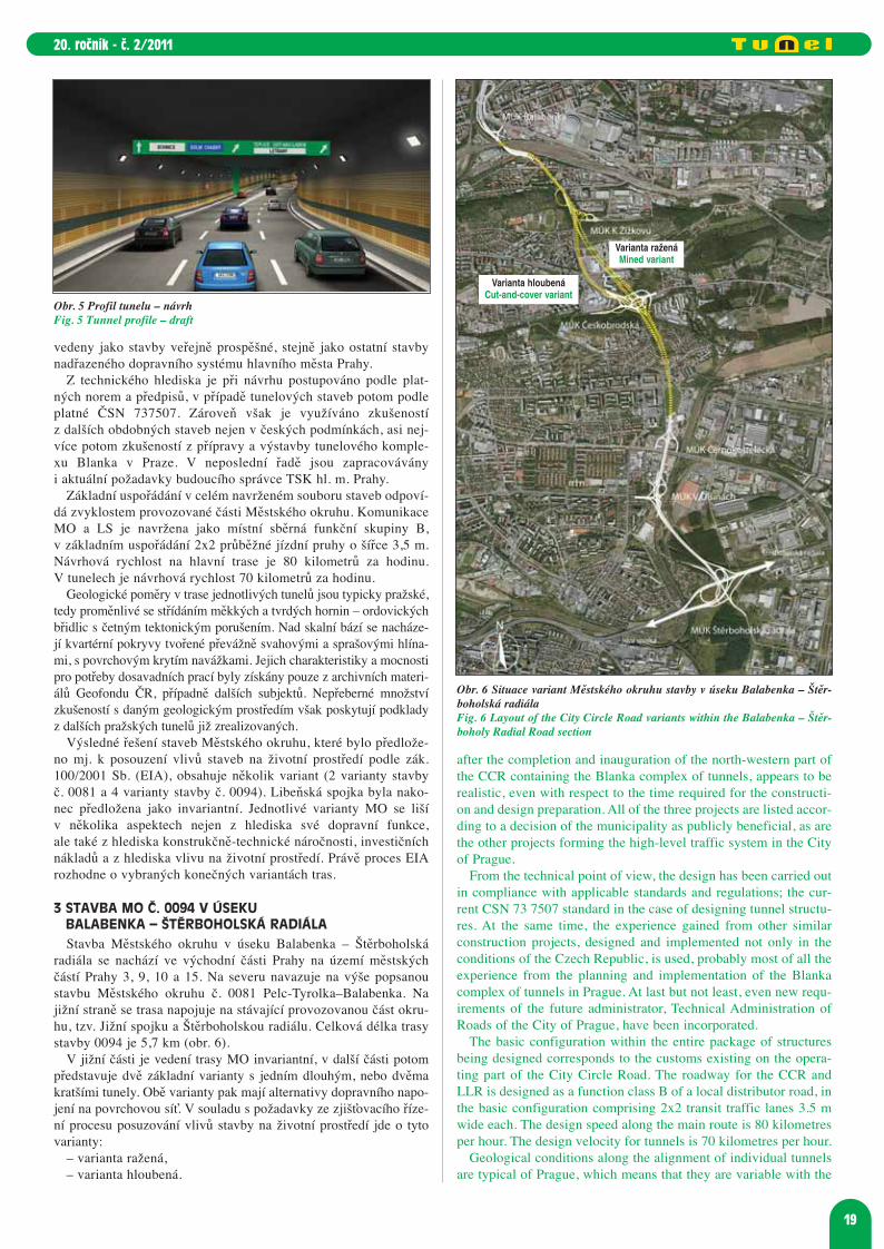
Stavba Městského okruhu v úseku Balabenka – Štěrboholskáradiála se nachází ve východní části Prahy na území městskýchčástí Prahy 3, 9, 10 a 15. Na severu navazuje na výše popsanoustavbu Městského okruhu č. 0081 Pelc-Tyrolka–Balabenka. Najižní straně se trasa napojuje na stávající provozovanou část okru-hu, tzv. Jižní spojku a Štěrboholskou radiálu. Celková délka trasystavby 0094 je 5,7 km (obr. 6).
V jižní části je vedení trasy MO invariantní, v další části potompředstavuje dvě základní varianty s jedním dlouhým, nebo dvěmakratšími tunely. Obě varianty pak mají alternativy dopravního napo-jení na povrchovou síť. V souladu s požadavky ze zjišťovacího říze-ní procesu posuzování vlivů stavby na životní prostředí jde o tytovarianty:
– varianta ražená,– varianta hloubená.
Obr. 5 Profil tunelu – návrhFig. 5 Tunnel profile – draft
Obr. 6 Situace variant Městského okruhu stavby v úseku Balabenka – Štěr-boholská radiálaFig. 6 Layout of the City Circle Road variants within the Balabenka – Štěr-boholy Radial Road section
Varianta ražená Mined variant
Varianta hloubenáCut-and-cover variant
tunel_2_11:tunel_3_06 20.6.2011 20:06 Stránka 19

20
20. ročník - č. 2/2011
Invariantní povrchová část v úseku Štěrboholská
radiála – MalešiceZačátek stavby č. 0094 je umístěn do prostoru mimoúrovňové kři-
žovatky se Štěrboholskou radiálou. V místě křížení s Rabakovskouulicí navazuje na stávající trasu MO vedoucí od Lanového mostu.Doposud je zde v provozu zúžený úsek komunikace vedený obou-směrně pouze v šíři jednoho jízdního pásu. V současnosti probíhádostavba druhého jízdního pásu ve směru na východ, která umožnízlepšení dopravní propustnosti a významně přispěje ke zvýšení bez-pečnosti provozu (obr. 7).
Trasa okruhu pokračuje severním směrem v souběhu se zkušeb-ní kolejí metra, několika mostními objekty překračuje kolejištěmetra trasy A u depa Hostivař a železniční nákladovou spojkuMalešice – Vršovice. Následuje mimoúrovňová křižovatkaV Olšinách řešící napojení hlavní trasy na síť místních komunika-cí. Dále trasa prochází průmyslovou oblastí Nových Strašnic, křížíulici Černokosteleckou a podél ulice Dřevčické je vedena dooblasti Malešic. Zde před Malešickým náměstím povrchový úsektrasy končí. Jeho délka činí 2,1 km.
Mimoúrovňová křižovatka s ulicí Černokosteleckou je řešenavýstavbou nového přemostění. Hlavní trasa MO bude zahloubenapod stávající komunikaci. Součástí stavby je i přeložka okruhempřerušené ulice Dřevčické.
S ohledem na ochranu životního prostředí a morfologii území,podmínky realizace a dopady v průběhu výstavby je v dalšímúseku trasa Městského okruhu vedena převážně v tunelech řeše-ných ve dvou variantách. Ražená varianta využívá ve větším roz-sahu tunelů ražených a představuje jeden souvislý tunelový úseks mezilehlou křižovatkou Českobrodská. Hloubená varianta nao-pak využívá převážně tunelů hloubených a sestává ze dvou samo-statných tunelů s mezilehlým povrchovým úsekem v MÚK Česko-brodská. U obou variant je jižní portál tunelu umístěn předMalešické náměstí.Varianta ražená v úseku Malešice – MÚK Balabenka
V ražené variantě podzemní trasa Městského okruhu pokračujeod železničního nádraží Malešice severním směrem do prostorumimoúrovňové křižovatky u Českobrodské ulice. Tento úsek buderealizován s využitím ražených tunelů. Dále trasa pokračuje hlou-beným tunelovým úsekem pod Českobrodskou ulicí a opět vstupu-je do raženého tunelu vedoucího až k Vysočanskému náměstí.Trasa je umístěna v těsné blízkosti nově vzniklého obytného sou-boru Zelené město a nákupního centra Kaufland. Severní portáltunelu je umístěn v ulici Spojovací, jejímž prostorem trasa okruhupokračuje od Vysočanského náměstí jako hloubený tunel. Celkovádélka tunelového komplexu je 2950 m. Za portálem následujepovrchové vedení ke stávajícímu podjezdu železniční tratě Praha
soft and hard rock alternating on it – the Ordovician shales withnumerous tectonic disturbances. Above the rock base there areQuaternary superficial deposits consisting mainly of slope loamsand secondary loess, with made ground covering the surface. Theircharacteristics and thickness, the knowledge of which is requiredfor the works performed till now, were obtained only from archivedocuments available at Geofond of the CR or other subjects, as thecase may be. In addition, an inexhaustible amount of experiencewith the given geological environment is provided by documentsfrom other Prague tunnels which have already been completed.
The resultant solution to constructions on the City Circle Roadwhich has been submitted among others to the assessment of the envi-ronmental impact of the structures according to the Law No. 100/2001Coll. (the EIA) contains several variants (2 variants for constructionlot 0081 and 4 variants for lot 0094). The Libeň Link Road solutionwas eventually submitted as invariant. Individual variants of the CCRdiffer in several aspects, not only as far as its traffic function is con-cerned, but also in terms of the technical structural exactingness,investment costs and the environmental impact. It will be the EIAwhat will decide about the final winning variants of the routes.
3 CCR CONSTRUCTION LOT NO. 0094 IN BALABENKA – ŠTĚRBOHOLY RADIAL ROAD SECTION
The construction of the City Circle Road in the section betweenBalabenka and the Štěrboholy Radial Road is found in the easternsector of Prague, in the area of municipal districts of Prague 3, 9,10 and 15. In the north it links to the above-mentioned constructi-on of the City Circle Road - lot 0081 between Pelc Tyrolka andBalabenka. On the southern side the route connects to the existing,operating part of the circle road, the so-called Southern Link Roadand the Štěrboholy Radial Road. The total length of constructionlot No. 0094 route is 5.7 km (see Fig. 6).
In the southern part, the CCR alignment is invariant, while twovariants exist for the adjoining section, comprising either one long ortwo shorter tunnels. Both variants have alternatives for the trafficconnection to the surface road network. In compliance with the requ-irements from the declaratory proceedings of the EnvironmentalImpact Assessment process, the following variants are dealt with:
- a mined variant- a cut-and-cover tunnel variant.
The invariant at-grade part within the Štěrboholy Radial Road – Malešice section
The beginning of the construction lot No. 0094 is placed to thearea of the grade-separated intersection with the Štěrboholy RadialRoad. In the location of the intersection with Rabakovská Street itconnects to the existing route of the CCR leading from the suspen-sion bridge. There is still a narrowed section of the road in opera-tion, with the width of a single carriageway serving for both direc-tions of traffic. The other carriageway, heading to the east, is cur-rently under construction. It will make the improvement of theroad carrying capacity possible and will significantly contribute toincreasing the level of the operational safety. (See Fig. 7)
The circle road route proceeds northwards in parallel with a testtrack of the metro. It crosses over the metro Line A rails (near theHostivař depot) and the Malešice – Vršovice connecting rail lineused for freight transport on several bridges. The V Olšináchgrade-separated intersection, solving the connection of the mainroute to the local road network, follows. Further the route passesacross the industrial area of Nové Strašnice, crosses Černokoste-lecká Street and, running along Dřevčická Street, heads toward thearea of Malešice. Here, before Malešice Square, the at-grade secti-on of the route terminates. Its length amounts to 2.1 km.
The grade-separated intersection with Černokostelecká Street issolved by means of a new bridge. The main route of the CCR will bedepressed below the existing road. Part of the construction lot is alsoa diversion of Dřevčická Street, which will be disrupted by the CCR.
Obr. 7 Vizualizace křižovatky – Městský okruh/Štěrboholská radiála (zdrojMott MacDonald Praha + C-Tech)Fig. 7 Visualisation of the intersection between the City Circle Road and theŠtěrboholy Radial Road (source: Mott MacDonald Praha + C-Tech)
tunel_2_11:tunel_3_06 20.6.2011 20:06 Stránka 20

21
20. ročník - č. 2/2011
With respect to the environmental protection and morphology ofthe area, implementation conditions and impacts during the courseof the construction, the next section of the City Circle Road routeis led mostly through tunnels, which are designed in two variants.The mined tunnel variant uses mined tunnels to a larger extent, for-ming one continuous tunnel section with the intermediate Česko-brodská intersection. Conversely, the cut-and-cover / cover-and-cut variant uses mainly cut-and-cover / cover-and-cut tunnels; itconsists of two independent tunnels with an intermediate at-gradesection at the grade-separated intersection (GSI) Českobrodská.Both variants have the southern portal located before MalešiceSquare. The mined variant in the Malešice – GSI Balabenka section
In its mined variant, the underground route of the City CircleRoad proceeds from the Malešice railway station northward, to thearea of the grade-separated intersection at Českobrodská Street.Mined tunnels will be used in this section. The route continuesfurther through a cut-and-cover tunnel section crossing under Čes-kobrodská Street and again enters a mined tunnel leading up toVysočany Square. The route is located in the close vicinity of thenewly developed residential complex Zelené Město (Green Town)and a Kaufland shopping centre. The northern portal of the tunnelis located in Spojovací Street. The Circle Road route continues wit-hin the footprint of this street from Vysočany Square througha cover-and-cut tunnel. The total length of the tunnel complex is2,950 m. An at-grade section follows behind the portal, up to theexisting subway under the Prague Hlavní Nádraží station – PragueLibeň rail line, behind which the construction enters the Balabenkaintersection, where it ends (see Fig. 10).
In the Českobrodská Street – Vysočany Square section, the routeis designed to run outside the footprints of Černobrodská andSpojovací Streets so that the surrounding area is affected by theconstruction and the structures themselves as little as possible.This solution is a deviation from the valid land-use plan, but it pro-vides a range of benefits both for the construction stage and for thefinal solution:
- The construction of mined tunnels means significantly lowerrestrictions upon the traffic in Spojovací and Českobrodská Streetsduring the course of the construction.
- It found a traffic solution for the area of Jarov which is moresuitable in town planning terms.
- It will make better connection of the new residential develop-ment (Zelené Město) during the construction possible.
- The living environment in the area of Jarov will improve, firstof all with respect to the noise and scenery.
- It is more advantageous from the operation-technical point ofview (the alternation of the at-grade and tunnel sections,
hlavní nádraží – Praha Libeň, za kterým stavba vstupuje do křižo-vatky Balabenka, kde končí (obr. 10).
Trasa okruhu v úseku Českobrodská – Vysočanské náměstí jeumístěna mimo prostor ulice Českobrodské a Spojovací tak, aby bylopři realizaci i vlastní stavbou okolní území zasaženo co nejméně.Toto řešení je změnou oproti platnému územnímu plánu, ale přinášířadu výhod jak pro etapu výstavby, tak i pro konečné řešení:
– Výstavba ražených tunelů znamená výrazně menší omezenídopravy ve Spojovací a Českobrodské ulici v průběhu realiza-ce stavby.
– Jedná se o nalezení urbanisticky vhodnějšího dopravního řeše-ní v prostoru Jarova.
– Umožní lepší napojení nové výstavby (Zelené město)v průběhu stavby.
– Dojde ke zlepšení životního prostředí v oblasti Jarova, zejmé-na s ohledem na hluk a krajinný ráz.
– Je výhodnější z provozně-technického hlediska (odpadá stří-dání povrchového a tunelového úseku – změna podmínek navozovce, vhodnější pro provozní zabezpečení).
– I proto bylo toto řešení variantně převzato do konceptu územ-ního plánu hl. m. Prahy z roku 2009.
– Dopravní řešení mimoúrovňové křižovatky Českobrodská jeuspořádáno do tří úrovní (obr. 8 a 9).
– Podzemní vedení hloubených tunelů Městského okruhu.– V úrovni terénu je navržena okružní křižovatka, která umož-
ňuje napojení povrchových komunikací do tunelu včetně plá-nované Jarovské spojky.
– V horní úrovni je prostor křižovatky doplněn pásem zeleně, zakterým jsou umístěny chodníky a stezky pro cyklisty.
Varianta hloubená v úseku Malešice – MÚK BalabenkaU hloubené varianty je první část úseku s raženým tunelem
vedeným od Malešického nádraží shodná s předchozí variantouraženou. Tunel délky 1060 m však končí u podjezdupod železniční tratí Malešice – Nákladové nádraží Žižkovu Českobrodské ulice. Za portálem trasa mostním objektem pře-kračuje plánovanou Jarovskou spojku, která propojí Jarov s ulicíŽelivského a na Městský okruh se napojí v mimoúrovňové křižo-vatce Českobrodská.
Po krátkém povrchovém úseku vedeném v prostoru Českobrod-ské ulice hlavní trasa okruhu opět vstupuje do tunelu. Hloubenýtunel délky 1760 m je veden pod povrchovou křižovatkou naJarově a pokračuje dál pod Spojovací ulicí. Ukončení tunelu jeplánováno obdobně jako u varianty ražené za Vysočanskýmnáměstím, opět s povrchovým pokračováním na Balabenku. UliceSpojovací bude v rámci stavby obnovena a zrekonstruována. Tatovarianta odpovídá původnímu řešení podle platného územníhoplánu z roku 1999.
Obr. 8 Vizualizace křižovatky ČeskobrodskáFig. 8 Visualisation of the Českobrodská intersection
Obr. 9 Vizualizace prostorového řešení křižovatky ČeskobrodskáFig. 9 Visualisation of the spatial design for the Českobrodská intersection
tunel_2_11:tunel_3_06 20.6.2011 20:06 Stránka 21

Alternativy dopravního řešení
Součástí obou návrhů je rovněž mimoúrovňová křižovatkaK Žižkovu, umístěná do prostoru ulice Pod Šancemi. Tato křižo-vatka je navržena s cílem umožnit napojení z prostoru ulicK Žižkovu, Spojovací a Novovysočanské na trasu MO v úsekumezi Balabenkou a Jarovem.
V rámci posouzení různých alternativ dopravního řešení bylapodrobně posouzena i možnost, kdy mimoúrovňová křižovatkaK Žižkovu není navržena. Z dopravního hlediska je toto řešeníméně výhodné, protože na stávajících povrchových komunikacíchzůstává větší podíl automobilové dopravy.
Součástí řešení je zároveň i mostní ekodukt přes ulici Spojovacív oblasti Balkán pro převod biokoridoru a několik pěších lávek potrase okruhu. V nezanedbatelné míře dojde výstavbou k re vi ta li -zaci dnes poměrně neutěšeného území v okolí trasy, využívanéhočasto pouze jako skládky, nebo stavební dvory.Tunely na stavbě MO 0094
Technické řešení hloubených tunelů v ulici Spojovací jes ohledem na potřebu zcela minimalizovat povrchové záborya výluky navrženo jako kombinace čelně odtěžovaných tunelů pod
i.e. changes in conditions on the roadway surface, is avoided,which is more suitable for the operational security).
This is also a reason why this solution was incorporated as analternative into the concept of the Master Plan of the City ofPrague from 2009.
The traffic solution for the Českobrodská grade-separated inter-section has three levels (see Figures 8 and 9):
- An underground route for the City Circle Road runningthrough cut-and-cover tunnels.
- An at-grade roundabout is designed allowing surface roads,including the planned Jarov Link Road, to link to the tunnel.
- At the upper level, the intersection space is complemented bya green belt and pavements and cycle tracks running behind it.
The cut-and-cover variant in the Malešice – GSI Balabenka section
As far as the cut-and cover / cover and-cut variant is concerned,the initial part of the section with the mined tunnel running fromMalešice railway station is identical with the previous mined vari-ant. But the 1,060 m long tunnel ends at the subway under theMalešice – Žižkov freight station line, at Českobrodská Street.Behind the portal the route crosses on a bridge structure over theplanned Jarov Link Road, which will link Jarov with ŽelivskéhoStreet and will connect to the City Circle Road at the Českobrod-ská grade-separated intersection.
After a short at-grade section running within the footprint ofČeskobrodská Street, the main route again enters a tunnel. The1,760 m long cut-and-cover / cover-and-cut tunnel is led under anat-grade intersection in Jarov and continues under SpojovacíStreet. The tunnel end is planned similarly as it is in the case of themined variant, i.e. behind Vysočany Square, again with the at-grade continuation toward Balabenka. Spojovací Street will berenewed and reconstructed within the framework of this project.This variant corresponds to the original solution contained in thevalid Master Plan from 1999. Traffic solution alternatives
Another part of the two proposals is the K Žižkovu grade-sepa-rated intersection, which is located at the area of Pod ŠancemiStreet. This intersection has been proposed with the aim of makingthe connection from the area of K Žižkovu, Spojovací andNovovysočanská Streets to the CCR possible.
Even the option wit-hout designing theK Žizkovu grade-separa-ted intersection wasassessed in detail withinthe framework of asses-sing various traffic soluti-on variants. This solutionis less advantageous interms of traffic becauseof the fact that a largerproportion of vehiculartraffic remains on theexisting at-grade roads.
In addition, part of thesolution is an ecoductbridge over SpojovacíStreet, in the Balkán area,transferring a bio-corri-dor, and several pedestri-an bridges to be builtover the Circle Roadroute. Owing to the con-struction, the today relati-vely dreary area along theroute, which is often used
22
20. ročník - č. 2/2011
Obr. 10 Vizualizace portálu tunelu za Vysočanským náměstímFig. 10 Visualisation of the tunnel portal behind Vysočany Square
Obr. 11 Situace variant Městského okruhu stavby v úseku Pelc-Tyrolka – BalabenkaFig. 11 Layout of the City Circle Road variants for the Pelc-Tyrolka – Balabenka section
Varianta s patrovým uspořádáním Stacked configuration variant
Varianta s tunelem pod Bílou skálou Variant with the tunnel under Bílá Skála rock
tunel_2_11:tunel_3_06 20.6.2011 20:06 Stránka 22

23
20. ročník - č. 2/2011
ochranou podzemních stěn a stropní desky nebo klasických hlou-bených tunelů. Vždy s rovným stropem a s uvažováním o společ-né střední stěně pro oba tubusy tunelu. Ostatní hloubené tunelovéčásti jsou plánovány pouze v klasickém uspořádání s realizacíz povrchu do předem zajištěné stavební jámy. Konstrukce tunelujsou buď klenbového, nebo rámového typu podle výšky nadloží.
Ražené tunely jsou opět navrženy pouze konvenčně technologiíNRTM. Možnost využití plnoprofilových tunelovacích strojů vylu-čuje velká variabilita profilů tunelu daná situačním a výškovýmřešením trasy. Zkušenosti z geologického prostředí v daném územíje možno získat hned z několika podzemních děl v nedalekémokolí. Například železniční tunel Malešický s délkou 358 ma zprovozněný v roce 1919.
4 STAVBA MO Č. 0081 V ÚSEKU PELC-TYROLKA – BALABENKA
Stavba Městského okruhu v úseku Pelc-Tyrolka – Balabenka senachází v severovýchodní části Prahy, v k. ú. Libeň. Na severuv prostoru mimoúrovňové křižovatky Pelc-Tyrolka u mostuBarikádníků tato část Městského okruhu navazuje na realizovanoustavbu MO č. 0079 s tunelem Královská obora. Na jihu je úsekukončen na Balabence, kde dále navazuje stavba Městského okru-hu Balabenka – Štěrboholská radiála. Celková délka trasy stavby0081 je 3,2 km (obr. 11).
Na základě vyhodnocení předchozích studijních prací je navrže-no vedení ve dvou variantách:
– s patrovým uspořádáním komunikace v ulici Povltavská,– s jednosměrným tunelem pod Bílou skálou.
Varianta s patrovým uspořádáním v Povltavské ulici
Směrem od Pelc-Tyrolky Městský okruh využívá koridor stáva-jící Povltavské ulice, která prochází mezi vltavským nábřežíma železniční tratí tzv. holešovické přeložky. Z důvodu omezenéhoprostoru je zde navrženo patrové vedení, kdy jsou jízdní pásy hlav-ní trasy umístěny nad sebou.
Pravý jízdní směr (na Balabenku) je veden v úrovni stávajícíPovltavské ulice. Levý jízdní směr (na Pelc-Tyrolku) v souběhustoupá. Po dosažení úrovně nad Povltavskou ulicí se postupněnasouvá do polohy nad dolní komunikaci. V průběhu zpracováníprojektové dokumentace byla pro tento náročný úsek trasy prove-dena optimalizace výškového, směrového a šířkového řešení.Cílem bylo zmenšit dopad stavební činnosti do prostoru přírodnípamátky Bílá skála, která se nachází severně od navržené trasy(nad železničním tunelem Bílá skála, nebo taky Libeňský).
Technické řešení mostu pro patrové vedení spočívá ve výstavbětří konstrukčně odlišných částí přemostění.
V první části se vnější (levý) pás komunikace postupně nasouvánad Povltavskou ulici. Tato část je řešena pomocí nosné konstruk-ce vetknuté do opěrné stěny.
Druhá část zajišťuje postupné směrové navedení horní komuni-kace nad spodní vozovku. Mostovka se vysouvá směrem od svahua je osazena na nosné příčné rámy.
Ve třetí části jsou oba směry komunikace vedeny nad sebou.Mostní konstrukce je navržena s příčným nosným systémem.Volný boční prostor umožňuje osvětlení a odvětrání vnitřního pro-storu vzniklé galerie (obr. 12).
Na konci galerie celkové délky 575 m se trasa Městského okru-hu postupně snižuje, vnitřní (pravý) pás se zahlubuje a přecházív hloubený tunel pod Povltavskou ulicí délky 540 m. Tunel pro-chází mezi železniční tratí a zástavbou Na Košince. Jeden jízdnísměr okruhu je zde veden v tunelu pod Povltavskou ulicí, druhýjízdní směr se nachází na stropní desce tunelu, v úrovni stávajícíPovltavské ulice. Vedení komunikací nad sebou zmenšuje nárokyna prostorové požadavky stavby a omezuje zatížení okolí hlukem.
Za východním portálem tunelu následuje přechodový úsek trasy,ve kterém se obě komunikace znovu dostávají do souběžnéhovedení. Zde je pravý jízdní směr veden na stávajících mostech přes
only for stockpiling or construction site facilities, will be revitali-sed to a non-negligible extent. Tunnels in the CCR construction lot 0094
The technical solution for the cut-and-cover tunnels in SpojovacíStreet is designed as a combination of cover-and-cut and cut-and-cover tunnels, taking into consideration the necessity for totallyminimising land acquisition and closing of traffic. In either case,flat roof decks and common central walls between the tunnel tubesare proposed. The other tunnel parts are of the classical cut-and-cover type, i.e. built in open trenches, in advance provided withexcavation support. The tunnel structures are either of the vaultedtype or rectangular frame type, depending on the overburdenheight.
The mined tunnels are again considered to be driven using theconventional NATM. The possibility of using full-face tunnelboring machines is excluded because of the high variability of thetunnel profiles, resulting from the horizontal and vertical align-ment of the route. The experience gained in the geological envi-ronment in the given area can be obtained from several underg-round works in the not so distant surroundings, for example the358 m long Malešice railway tunnel, which was opened to trafficin 1919.
4 CCR CONSTRUCTION LOT NO. 0081 WITHIN PELCTYROLKA – BALABENKA SECTION
The construction lot within the Pelc Tyrolka – Balabenka secti-on of the City Circle Road is found in the north-eastern part ofPrague, the cadastral district of Libeň. In the north, in the area ofthe Pelc Tyrolka grade-separated intersection next to theBarikádníků Bridge, this part of the City Circle Road links to theCCR construction lot No. 0079 being under construction, contai-ning the Královská Obora tunnel. In the south, the section ends atBalabenka, where it is further continued by the Balabenka – Štěr-boholy Radial Road lot of the City Circle Road. The total length ofthe construction lot No. 0081 route is 3.2 km (see Fig. 11).
Two variants of the route are under consideration on the basis ofthe assessment of previous studies:
- A variant with a stacked configuration of the road in Po -vltavská Street.
- A variant with a unidirectional tunnel under the Bílá Skála rock.The variant with a stacked configuration in Povltavská Street
In the direction from Pelc Tyrolka, the City Circle Road uses thecorridor running along Povltavská Street, which leads between theVltava River embankment and the railway track of the so-calledHolešovice Diversion Line. Because of the restricted space in thisarea, a stacked configuration is designed here, with the carriage-ways of the main route located one above the other.
The right-hand direction of traffic (toward Balabenka) is led at thelevel of existing Povltavská Street. The parallel left-hand directionof traffic (toward Pelc Tyrolka) rises alongside. After reaching therequired level above Povltavská Street, it is gradually shifted to theposition above the lower roadway. The vertical and horizontal align-ment and the width design for this difficult section of the route wereoptimised during the course of the work on the design. The objecti-ve was to diminish the impact of construction activities on the areaof the Bílá Skála Natural Monument, which is found north of theproposed route (above the Bílá Skála or Libeň railway tunnel).
The technical solution for the bridge required for the stackedconfiguration comprises three structurally different parts of thebridge:
In the first part, the outer (left) carriageway is gradually shiftedabove Povltavská Street. This part is solved using a load-bearingstructure fixed in a retaining wall.
The second part provides gradual directional insertion of theupper roadway over the lower carriageway. The bridge deck is
tunel_2_11:tunel_3_06 20.6.2011 20:06 Stránka 23

24
20. ročník - č. 2/2011
Primátorskou a Zenklovu ulici. Pro levou polovinu okruhu je navr-žena nová souběžná komunikace s novým přemostěním ulicPrimátorská a Zenklova. Mimoúrovňová křižovatka U Kříže zajiš-ťuje napojení Městského okruhu severním směrem na Proseckouradiálu. Toto spojení řeší samostatná plánovaná stavba Libeňskéspojky popsaná dále. Od mimoúrovňové křižovatky U Kříže trasaokruhu využívá již v 80. letech částečně vybudovaný úsek komu-nikace v ulici Čuprova. Dobudována zde fakticky bude pouzedruhá polovina komunikace Městského okruhu.
Podmínkou dopravního řešení této části trasy je kromě jinéhoumožnit výhledové napojení plánované II. etapy Vysočanské radi-ály. Trasa stavby 0081 je ukončena na mimoúrovňové křižovatceBalabenka.
Stávající estakáda přes ulici Sokolovskou a ulici Na Žertváchbyla navržena pro jednu polovinu Městského okruhu, a proto budepo rekonstrukci převádět levý jízdní směr. Pro pravý jízdní směrhlavní trasy je navržena výstavba nového souběžného přemostění.Pro napojení uliční sítě budou využity stávající křižovatkovérampy, spolu s velkou okružní křižovatkou umístěnou na konciulice na Žertvách (obr. 13).Varianta s tunelem pod Bílou skálou
Ve druhé variantě je v úseku Košinka – Pelc-Tyrolka polovinaMěstského okruhu ve směru z Balabenky vedena raženým tunelempod Bílou skálou délky 1490 m. Tunel je pouze jednosměrnýdvoupruhový a jeho trasa severně obchází starý železniční tunel.
shifted in the direction from the slope; it is placed on transverseload-bearing beams.
In the third part, both directions of the road run one above theother. A transverse load-bearing structure is designed for the brid-ge. The open space on the side makes lighting and ventilation ofthe inner space of the gallery possible (see Fig. 12).
At the end of the gallery with the total length of 575m, the CityCircle Road route gradually descends; the inner (right-hand) carria-geway gradually sinks, passing into a 540 m long cut-and-covertunnel under Povltavská Street. The tunnel passes between the rail-way track and buildings surrounding Na Košince Street. One direc-tion of traffic on the circle road in this location runs through the tun-nel under Povltavská Street, the opposite direction roadway isfound on the tunnel roof deck, at the level of the current PovltavskáStreet. The stacked configuration reduces requirements of the struc-ture for space and diminishes noise pollution in the surroundings.
A transition section of the route follows after the eastern portalof the tunnel. In this section both carriageways get again into theparallel position. The right-hand carriageway is led on existingbridges over Primátorská and Zenklova Streets. A new, parallelroad with a new bridge over Primátorská and Zenklova Streets isdesigned for the left-hand half of the circle road. The U Křížegrade-separated intersection provides the connection of the CityCircle Road northward to the Prosek Radial Road. This connectionis solved by means of a separately planned construction of theLibeň Link Road, which is described below. From the U Křížegrade-separated intersection the circle road route uses the road sec-tion in Čuprova Street, which was partially developed in the 1980s.Practically only the other half of the City Circle Road carriagewaywill be added in this location.
A condition for the traffic solution for this part of the route is,among others, that the future connection of the planned stage II ofthe Vysočany Radial Road will be possible. The construction lot0081 route terminates at the Balabenka grade-separated intersection.
The existing viaduct over Sokolovská and Na Žertvách Streetswas designed for one half of the City Circle Road. For that reasonit will carry the left-hand direction of traffic after reconstruction.The construction of a new, parallel bridge is designed for the right-hand direction of traffic on the main route. The existing intersecti-on ramps together with a large roundabout located at the end of NaŽertvách Street (see Fig. 13) will be used for the connection of thenetwork of streets. The variant with the tunnel under Bílá Skála rock
In the second variant, a half of the route in the Košinka – PelcTyrolka section of the City Circle Road in the direction fromBalabenka is led through a 1,490 m long mined tunnel runningunder Bílá Skála rock. The tunnel is only unidirectional, with twolanes; its alignment bypasses the old railway tunnel on the northernside. Thus the space in Povltavská Street is vacated for the at-gradealignment of the opposite direction of traffic on the circle road hea-ding toward Balabenka. The remaining section of this variant bet-ween Košinka and Balabenka is identical with the variant using thestacked configuration.
Part of the City Circle Road project is a design for flood preven-tion measures concerning the road part running along the riverembankment. Flood defence embankments will link to barriers atthe Pelc Tyrolka intersection. Taking into consideration the appro-priate incorporation into the landscape, the new embankment willserve for the development of a new cycle way. In addition, severalpedestrian bridges and subways will be constructed and the areaassociated with the project will be revitalised. Tunnels within the CCR construction lot 0081
The tunnels including the gallery are assumed to be built usingthe classical cut-and-cover method, i.e. in a shelf or a pre-stabili-sed construction trench. The reinforced concrete structure is desig-
Obr. 12 Vizualizace galerie patrového uspořádání MO v ulici Povltavská (v pozadí železniční tunel Libeňský) (zdroj Mott MacDonald Praha + C-Tech)Fig. 12 Visualisation of the gallery at the stacked configuration of the CCRin Povltavská Street (the Libeň railway tunnel in the background) (source:Mott MacDonald Praha + C-Tech)
Obr. 13 Vizualizace Městského okruhu v prostoru BalabenkyFig. 13 Visualisation of the City Circle Road in the area of Balabenka
tunel_2_11:tunel_3_06 20.6.2011 20:06 Stránka 24

Uvolňuje tak prostor v Povltavské ulici pro povrchové vedení dru-hého jízdního směru okruhu směřujícího na Balabenku. Zbývajícíúsek této varianty v úseku Košinka – Balabenka je shodnýs variantou s patrovým uspořádáním.
Součástí stavby Městského okruhu je i návrh protipovodňovýchopatření podél nábřežní části komunikace. Protipovodňové valybudou navazovat na bariéry u křižovatky Pelc-Tyrolka. S ohledemna vhodné začlenění do krajiny bude vzniklé zemní těleso sloužitpro zřízení cyklostezky. Vybudováno bude rovněž i několik láveka podchodů spolu s revitalizací souvisejícího území.Tunely na stavbě MO 0081
Hloubené tunelové části včetně galerie jsou plánovány v kla -sickém uspořádání s realizací z povrchu do předem zajištěnéhoodřezu, nebo stavební jámy. Železobetonová konstrukce je s ohle -dem na nutnost minimálního zahloubení pod železniční trať nebodruhý jízdní směr MO řešena jako rámová s rovným stropem.
Ražený tunel se předpokládá vzhledem k rozsahu a dispozičnímpožadavkům realizovat technologií NRTM. Při jeho výstavbě budetřeba zohlednit zkušenosti z výstavby železničního tunelu(Libeňský, dl. 331 m), který byl realizován v letech 1966–1975pomocí modifikované belgické (podchycovací) metody. Běhemvýstavby se tehdy plně projevily nepříjemné vlastnosti křemenco-vých vrstev. Po vyhloubení stavební jámy obou křídel východníhoportálu se daly do pohybu zastižené mocné lavice křemenců spa-dající do jámy pod úhlem cca 45°. Jejich pohyb byl cca 10–20cm/den. V takto komplikovaném geologickém prostředí budeproto třeba počítat s velkými deformacemi ostění tunelu, sedánímnadloží a celkově s vysoce náročnou ražbou.
5 STAVBA Č. 8313 LIBEŇSKÁ SPOJKA
Libeňská spojka je svým významem důležitou součástí systémuhlavních komunikací v severovýchodní části Prahy. Tato stavbazajišťuje úplné dopravní propojení mezi Proseckou radiáloua Městským okruhem, krom jiného doplňuje neúplnou mimoúrov-ňovou křižovatku Prosecké radiály a Městského okruhu na Pelc-Tyrolce, čímž odklání dopravu jinak směřující do uliceV Holešovičkách. Proto musí být připravována a uvedena do pro-vozu společně s navazujícími stavbami Městského okruhu č. 0081a 0094. Celý úsek Libeňské spojky se nachází na území městskéčásti Praha 8 a jeho délka činí 1,35 km (obr. 14).
ned as a frame with a flat roof deck, taking into consideration thenecessity for minimising the depth of the crossing under the rail-way track and the passage under the opposite CCR carriageway.
It is assumed, taking into consideration the extent and require-ments for the route layout, that the mined tunnel will be construc-ted using the NATM. In addition, the experience gained during theconstruction of the railway tunnel (the 331 m long Libeň tunnel)will have to be taken into account. This tunnel was built in 1966-1975 using the modified flying-arch (Belgian) system. At that time,the unpleasant properties of quartzite beds took full effect. Afterexcavating the construction pit for both wings of the eastern por-tal, thick quartzite beds dipping into the pit at the angle of about45° started to move. The rate of their movement was approximate-ly 10-20 cm per day. It is necessary to allow for complicationsassociated with this geological environment, manifesting themsel-ves in the form of large deformations of the tunnel lining and sett-lement of the overburden, resulting in a highly demanding tunnel-ling process.
5 CONSTRUCTION LOT NO. 8313: LIBEŇ LINK ROAD
The Libeň Link Road is, in terms of its importance, a significantpart of the system of main roads in the north-eastern part ofPrague. This structure secures full traffic connection between theProsek Radial Road and the City Circle Road. In addition, it supp-lements the incomplete grade-separated intersection between theProsek Radial Road and the City Circle Road in Pelc Tyrolka,diverting the traffic which would otherwise head to V Hole -šovičkách Street. For that reason the Libeň Link Road must beprepared and opened to traffic jointly with the linking City CircleRoad construction lots No. 0081 and 0094. The entire 1.35 kmlong Libeň Link Road is found in the area of the municipal districtof Prague 8 (see Fig. 14).
On the southern side, the route starts in the area of the Balabenka– U Kříže intersection node, for which even the future connection ofthe Vysočany Radial Road to the CCR is being prepared. On the nort-hern side, it ends inside the Vychovatelna grade-separated intersecti-on. A range of variants were examined within the framework of see-king an optimal solution, first of all the possibility to lead the two car-riageways of the Libeň Link Road separately through cut-and-covertunnels under Zenklova, Vosmíkových and Braunerova Streets. The
possibility of using minedtunnels was also examined.These solutions did not turnout to be suitable, first of allfor the reasons of the layoutand economy. On the onehand, the resultant invariantsolution more or less main-tains the effort to keep to thefootprint of Zenklova Street,as it is stipulated in theMaster Plan, on the otherhand, it uses a progressivetechnical solution. Owing totaking advantage of the ter-rain configuration in thearea of the connection of theCity Circle Road to Prosec -ká Street, the Libeň LinkRoad gets to the stackedconfiguration. This solutionsignificantly reduces overallrequirements of the con-struction for spaces and thelink road route can passacross the most critical loca-tions in Zenklova Street wit-hout intervention in adjacentbuildings.
25
20. ročník - č. 2/2011
Obr. 14 Situace Libeňské spojkyFig. 14 Layout of the Libeň Link Road
Prosecká radiála – Prosek Radial Road
Vysočanská radiála – Vysočany Radial Road
tunel_2_11:tunel_3_06 20.6.2011 20:06 Stránka 25

26
20. ročník - č. 2/2011
Na jižní straně začíná trasa v prostoru křižovatkového uzluBalabenka – U Kříže, kde je připravováno i budoucí připojeníVysočanské radiály na MO. Na severní straně pak končív mimoúrovňové křižovatce Vychovatelna. V rámci hledání opti-málního řešení byla zkoumána řada variant, především pak mož-nosti vést oba směry komunikace Libeňské spojky samostatněhloubenými tunely, ulicemi Zenklovou, Vosmíkových a Brau -nerovou. Rovněž byla prověřena možnost využití tunelů ražených.Tato řešení se však neprokázala jako vhodná, jednak z prostorovědispozičních důvodů a jednak z důvodů ekonomických. Výslednéinvariantní řešení se tak sice z větší části stále snaží držet stopuZenklovy ulice, jak je dáno v platném územním plánu, avšak zapoužití progresivního technického řešení. Využitím konfiguraceterénu v prostoru napojení Městského okruhu na Proseckou ulicise komunikace spojky dostává do patrového uspořádání. Tím sevýrazně redukují plošné nároky stavby a trasou spojky lzev nejkritičtějších místech projít Zenklovou ulicí bez zásahu dookolní zástavby.
Stavba Libeňské spojky začíná v oblasti mimoúrovňové křižo-vatky U Kříže, kde se napojuje na Městský okruh. Trasa LS nej-dříve kříží Proseckou ulici, za kterou vchází do prostoru již zde-molované zástavby mezi ulicemi Zenklova a Fr. Kadlece. Výškovéřešení v tomto úseku využívá prostorové dispozice území.Stoupající pás směrem na Vychovatelnu podchází Proseckou ulicitunelem, zatímco směr klesající ji překonává mostem tak, aby semohl napojit na stávající zárodek mostní konstrukce na MO. Vestávající úrovni je navržena okružní křižovatka umožňující napo-jení na Městský okruh a Libeňskou spojku z uliční sítě (obr. 16).
Oba dopravní směry Libeňské spojky dále pokračují severnímsměrem pod Zenklovou ulicí ve společném hloubeném tunelu,který je navržen s vertikálním uspořádáním obou tubusů nad sebou(obr. 17). Od křižovatky ulic Zenklova a Vosmíkových trasa smě-řuje do dvorního prostoru bloku mezi oběma ulicemi a pokračujek náměstí Na Stráži. V tomto úseku dochází k postupnému pře-chodu od patrového uspořádání k horizontálnímu uspořádání tune-lových tubusů vedle sebe.
Trasa Libeňské spojky dále vede pod náměstím Na Stráži opětdo prostoru Zenklovy ulice směrem pod mostní konstrukci mimo-úrovňové křižovatky Vychovatelna, kde je ukončena (obr. 18).Napojení na Proseckou radiálu a ostatní komunikace je zajištěnosamostatnými rampami. Celková délka tunelu dosahuje 865 m.
Navržené řešení Libeňské spojky minimalizuje nutné demolicepodél Zenklovy ulice a díky originálnímu technickému řešeníomezuje trvalé i dočasné stavební zásahy do území. Vlivem dlou-hodobé stavební uzávěry a nedokončené asanace pro tehdy ještěpovrchově vedenou LS (obr. 15) je území kolem budoucí LSpoměrně neutěšené se zcela narušenou urbanistickou strukturou.
The construction of the Libeň Link Road starts in the area of theU Kříže grade-separated intersection, where it links to the CityCircle Road. Its route first crosses Prosecká Street and behind itenters the area of already demolished buildings between Zenklovaand Fr. Kadlece Streets. The vertical alignment design for this sec-tion takes advantage of the spatial configuration of the area. Thecarriageway ascending in the direction of Vychovatelna passesunder Prosecká Street through a tunnel, whilst the descendingdirection overcomes it by means of a bridge allowing it to link tothe existing stub of a bridge on the CCR. The roundabout allowingthe connection to the City Circle Road and the Libeň Link Roadfrom the street level is designed to be at the existing level (see Fig. 16).
Both carriageways of the Libeň Link Road further proceednorthwards, under Zenklova Street, through a common cover-and-cut tunnel, which is designed as a stacked configuration structure(see Fig. 17). From the intersection between Zenklova andVosmíkových Streets, the route heads to a courtyard of the blockfound between these streets and proceeds to Na Stráži Square. Inthis section the stacked configuration gradually passes toa horizontal configuration with the tunnels running side-by-side.
The Libeň Link Road is further led under Na Stráži Square backto the footprint of Zenklova Street, in the direction heading underthe bridge structure of the Vychovatelna grade-separated intersec-tion, where it is terminated (see Fig. 18). The connection to theProsek Radial Road and other roads is secured by independentramps. The total length of the tunnel amounts to 865 m.
The solution proposed for the Libeň Link Road (LLR) minimi-ses demolitions necessary along Zenklova Street and, owing to theoriginal technical solution, curtails both permanent and temporarystructural interventions to be performed in the area. As a result ofa long-term prohibition of construction and the fact that the reha-bilitation of the area required for the at that time at-grade route ofthe Libeň Link Road has not been finished (see Fig. 15), the areaalong the future LLR is in a relatively dismal condition, with theurban structure completely disturbed. Despite this fact, the imple-mentation of the solution contained in the valid Master Plan wouldrequire a significant amount of demolition and other interventionsin private property. Anyway, the experience gained not only inPrague suggests that the possibility of coping with these problemsis often beyond time-related and economic capacity of the projectowner. This is why a technically more complex variant was ado-pted, requiring minimum intervention in the existing developmentand, on the other hand, providing larger space for the possibility ofsubsequent upgrading of the area. At the same time, these werealso the reasons why the new concept of the Libeň Link Road with
Obr. 15 Fotografie modelu původního povrchového řešení Libeňské spojkyz 80. letFig. 15 A picture of the model of the original at-grade design for the LibeňLink Road from the 1980s Obr. 16 Vizualizace křižovatky U Kříže
Fig. 16 Visualisation of the U Kříže intersection
tunel_2_11:tunel_3_06 20.6.2011 20:06 Stránka 26

27
20. ročník - č. 2/2011
Přesto by si realizace řešení podle platného územního plánu vyžá-dala značné množství demolic a dalších zásahů do soukroméhomajetku. Zkušenosti nejen z Prahy však naznačují, že možnostvypořádání se s těmito problémy často překračuje jak časové, taki ekonomické možnosti investora. Proto byla přijata varianta tech-nicky náročnější, avšak s minimálním zásahem do stávající zástav-by, a naopak ponechávající větší prostor pro možnost následnéhodotvoření území. Zároveň i z těchto důvodů byla nová koncepceLibeňské spojky s patrovým tunelem zapracována do konceptunového územního plánu.Tunely na stavbě LS 8313
Pro urychlení doby výstavby a omezení jejích dopadů na obslu-hu území byl pro konstrukce hloubených tunelů umístěných doprostoru Zenklovy ulice navržen systém čelního odtěžování profi-lu tunelu pod ochranou konstrukčních podzemních stěna definitivní stropní konstrukce. Tento systém spočívá ve vytvoře-ní svislých podzemních stěn vetknutých do únosného podložíz povrchu. Následně se do mělké stavební jámy vytvoří definitiv-ní stropní deska uložená na podzemní stěny. Po dokončení stropnídesky a jejím zasypání se realizuje definitivní úprava povrchua následně dojde k jeho zprovoznění.
Vlastní odtěžování profilu tunelu bude probíhat z otevřenýchstavebních jam umístěných mimo prostor dnešních komunikací.Provádění se pak předpokládá ve dvou úrovních daných mezileh-lou deskou oddělující oba tubusy tunelu.
Úseky v otevřených stavebních jámách mimo uliční prostorbudou realizovány klasickým systémem výstavby hloubenýchtunelů z povrchu s následným zásypem.
6 ZÁVĚR
Soubor staveb Městského okruhu č. 0081 a 0094 a Libeňskéspojky č. 8313 se v současné době nachází ve fázi posuzovánívlivů záměrů na životní prostředí podle zákona 100/2001 Sb.(EIA). Příslušným orgánem pro vydání stanoviska k posuzovánívlivů stavby na životní prostředí je Ministerstvo životního prostře-dí ČR.
Smyslem realizace popisovaných staveb je dokončeníMěstského okruhu, které umožní převedení co největšího počtudopravních vztahů ze stávající komunikační sítě na nadřazenýsystém komunikací. Dojde k oddělení průjezdné dopravy od hro-madné dopravy, pěších a dopravy místní. Tím může být naplněnhlavní cíl, a sice plošné snížení negativních účinků dopravy naživotní prostředí a ochránění obytné zástavby ve městě od exhalacía hluku.
Z dopravně-inženýrských výpočtů provedených v rámci technic-kých podkladů pro dokumentaci EIA vyplývá, že zprovozněnímvýchodní části MO a navazujících komunikací dojde ke snížení
the stacked tunnel was incorporated into the concept of the newland use plan. Tunnels within the construction lot Libeň Link Road LS 8313
The cover-and-cut technique with the excavation carried outunder the protection of structural diaphragm walls and the finalroof deck structure has been designed for the construction of thetunnels in the footprint of Zenklova Street. This system is based onthe construction of vertical diaphragm walls installed from theground surface, fixed in a competent base. Then a final roof deckis cast in a shallow construction trench, resting on the diaphragmwalls. When the roof deck is finished and backfilled, the final tre-atment of its surface takes place and the slab structure is open totraffic.
The tunnel profile excavation itself will proceed from open con-struction trenches located outside the space of today’s roads. It isexpected that the excavation will be carried out in two stages givenby the intermediate slab dividing the two tunnel tubes.
The sections in open construction trenches outside the streetspace will be constructed using the classical cut-and-cover tech-nique.
6 CONCLUSION
The package of the City Circle Road construction lots No. 0081and 0094 and the Libeň Link Road No. 8313 is currently found atthe stage during which the impacts of the plans on the living envi-ronment are being assessed according to the Law No. 100/2001Coll. (the EIA). The administrative body competent to issue theopinion on assessing of the environmental impact is the Ministryof the Environment of the Czech Republic.
The purpose of the above-mentioned constructions is the com-pletion of the City Circle Road, owing to which it will be possibleto transfer as large as possible number of traffic relations from theexisting road network to the high-level system of roads. The tran-sit traffic will be separated from mass transport, pedestrians andshort-distance traffic. Accomplishing it, the main objective may bemet, i.e. the area-wide reduction of negative effects of traffic on theliving environment and protection of residential developments inthe city against exhaust emissions and noise.
It follows from traffic engineering calculations carried out wit-hin the framework of technical feedback for the EIA documentsthat by opening the eastern part of the CCR and linking roads totraffic the traffic volume in many today critical locations will bereduced. This is first of all the case of the following streets: JanaŽelivského, Koněvova, Malešická, Českobrodská, K Žižkovu,Freyova, Vysočanská, Prosecká, Zenklova, Kbelská, Průmyslová,
Obr. 17 Tunely vertikálního uspořádání tubusů v Zenklově uliciFig. 17 Stacked configuration tunnels in Zenklova Street
Obr. 18 Vizualizace křižovatky Vychovatelna a náměstí Na StrážiFig. 18 Visualisation of the Vychovatelna intersection and Na Stráži Square
tunel_2_11:tunel_3_06 20.6.2011 20:06 Stránka 27

28
20. ročník - č. 2/2011
intenzit dopravy na řadě dnes kritických míst. Jedná se předevšímo ulice Jana Želivského, Koněvova, Malešická, Českobrodská,K Žižkovu, Freyova, Vysočanská, Prosecká, Zenklova, Kbelská,Průmyslová, V Holešovičkách a jejich křižovatky, ale rovněži Legerovu, Wilsonovu, Argentinskou a ulici 5. května.
Protože realizací předmětných staveb dojde k dokončení celéhoMěstského okruhu a bude nabídnuta alternativa k řadě stávajícíchkomunikací, bude dále možné reálně přistoupit k omezení prů-jezdné i cílové automobilové dopravy v oblasti uvnitř Městskéhookruhu. Zprovoznění celého Městského okruhu tak umožní zave-dení některého ze způsobů regulace dopravy (například výkonovézpoplatnění-mýto). Získané prostředky z výběru mýta bude možnézpětně využít například jako investice do MHD.
Pro dosažení maximálního kladného efektu na životní prostředía splnění legislativních požadavků na hygienické limity všaknestačí pouze převést dopravu na kvalitnější trasu. Je třeba při-jmout další opatření, která povedou k vhodnějšímu rozdělení pře-pravní práce mezi jednotlivé druhy dopravy a k intenzifikaci fak-torů zlepšujících životní prostředí ve městě vůbec. Nejedná se tedypouze o klasické dopravní plánování, ale spíše o celkovou doprav-ní a enviromentální koncepci v Praze. Z těchto důvodů bylov rámci dokumentace EIA souboru staveb MO+LS přijato několikopatření směřujících právě k dalšímu zlepšování životního pro-středí a ke splnění hygienických limitů.
Mezi ta nejdůležitější opatření patří:– rozsáhlé vedení trasy v tunelech– realizace protihlukových bariér a izolační zeleně– zavedení emisních zón EURO 3 a EURO 4 na území Prahy– návrh plošné regulace automobilové dopravy například zave-
dením mýta– omezení vjezdu nákladních vozidel do prostoru uvnitř
Městského okruhu– zavedení účinných prostředků pro aktivní řízení rychlosti
a skladby dopravy
Tato opatření byla následně schválena Radou hl. m. Prahyv usnesení 1701 ze dne 21. 9. 2010 a stanou se nedílnou podmín-kou stanoviska MŽP ČR k dokumentaci vydaného v rámci proce-su EIA.
V procesu přípravy a ve způsobu realizace navržených stavebnejsou doposud zcela ujasněny veškeré detaily. Konečné řešeníjistě dozná změn, ať bude v procesu EIA vybrána jakákoli varian-ta. Přesto věřme, že bude pro dokončení Městského okruhuv Praze dostatek vůle (politické, občanské) a dostatek finančníchprostředků tak, aby mohl sloužit nejen všem obyvatelům Prahy conejdříve.
ING. PAVEL ŠOUREK, [email protected], SATRA, s. r. o.
Recenzoval: Ing. Jaromír Zlámal
Pozn.: Při tvorbě tohoto článku bylo čerpáno zejménaz příspěvku Dokončení Městského okruhu v Praze ve sborníkukonference Podzemní stavby Praha 2010 autorů P. Šourek, L.Rákosník oba SATRA, s. r. o., a M. Hrdlička, P. Hanuš oba MottMacDonald Praha, s. r. o.
V Holešovičkách and their intersections, but also Legerova,Wilsonova, Argentinská and 5. května Streets.
Because of the fact that the implementation of the above-menti-oned constructions will result in the completion of the entire CityCircle Road and an alternative will be available to many existingroads, it will be further possible to set about restrictions on thethrough traffic and terminating traffic in the area encircled by theCity Circle Road. Opening of the entire City Circle Road to trafficwill make the introduction of some of the traffic management sys-tems (e.g. a distance-based tolling system) possible. It will be pos-sible to use the means gained through the collection of toll, forexample as funds to be invested in the urban mass transit system.
However, it is not enough for achieving a maximum positiveeffect on the environment and complying with legislative require-ments for sanitary limits only to transfer traffic to a higher qualityroute. It is necessary to adopt other measures which will lead tomore suitable distribution of traffic performance among individualtransportation modes and intensify the factors improving the urbanenvironment as the whole. It is not only the case of classical tran-sport planning; it is rather an overall transportation and environ-mental concept for Prague. For the above-mentioned reasons, seve-ral measures were adopted aimed at further improving of the livingenvironment and complying with sanitary limits.
The following measures belong among the most important:- Extensive placing of the route in tunnels - Providing noise barriers and noise isolating green areas - Introducing low emission zones in Prague, meeting EURO 3
and EURO 4 limits - Proposing area-wide vehicular traffic regulation, e.g. by intro-
ducing a tolling system - Restricting the entry of goods vehicles to the space encircled
by the City Circle Road - Introducing effective means of active control of speed and
composition of traffic
The above measures were subsequently approved by the PragueCity Council in the resolution No. 1701 of 21st September 2010.They will become an inseparable part of the opinion of theMinistry of the Environment on documents issued within the EIAprocess.
Some details regarding the planning process and the way inwhich the proposed structures are to be implemented have not beencompletely clarified yet. The final solution will certainly undergochanges, no matter which of the variants is selected in the EIA pro-cess. Still, let us believe that there will be sufficient goodwill(among politicians and citizens) and sufficient financial meansallowing the completion of the City Circle Road in Prague so thatit can serve all Prague citizens at the soonest.
ING. PAVEL ŠOUREK, [email protected], SATRA, s. r. o
Note: This paper was prepared using first of all the paperCompletion of the City Circle Road project, Prague published inthe Proceedings of the Underground Construction Prague 2010Conference by the authors P. Šourek, L. Rákosník, both fromSATRA, s.r.o., and M. Hrdlička, P. Hanuš, both from MottMacDonald Praha, s.r.o.
LITERATURA / REFERENCESDokumentace vlivů stavby na životní prostředí (EIA) souboru staveb MO+LS. Praha : SATRA, s. r. o., Mott MacDonald Praha, s. r. o.,Envisystem, s. r. o., 2010.Optimalizace staveb sítě hlavních komunikací v Praze. Praha : SATRA, s. r. o., 2006.Vyhledávací, ověřovací, dopravní, urbanistické a technické studie MO a LS. Praha : Mott MacDonald Praha, s. r. o., SATRA, s. r. o.,1998–2010.
tunel_2_11:tunel_3_06 20.6.2011 20:06 Stránka 28