tunable lens by spatially varying liquid crystal … 361.pdftunable lens by spatially varying liquid...
TRANSCRIPT

Tunable lens by spatially varying liquid crystal pretilt anglesMan-Chun Tseng, Fan Fan, Chung-Yung Lee, Anatoli Murauski, Vladimir Chigrinov et al. Citation: J. Appl. Phys. 109, 083109 (2011); doi: 10.1063/1.3567937 View online: http://dx.doi.org/10.1063/1.3567937 View Table of Contents: http://jap.aip.org/resource/1/JAPIAU/v109/i8 Published by the American Institute of Physics. Related ArticlesBiaxial order and a rotation of the minor director in the nematic phase of an organo-siloxane tetrapode by theelectric field J. Chem. Phys. 136, 094513 (2012) Sub-hertz relaxation process in chiral smectic mixtures doped with silver nanoparticles Appl. Phys. Lett. 100, 073112 (2012) The effect of salt on ion adsorption on a SiOx alignment film and reduced conductivity of a liquid crystal host J. Appl. Phys. 111, 024501 (2012) Influence of temperature on dynamics of birefringence switching in photochromic nematic phase J. Appl. Phys. 110, 113104 (2011) Electro-optical response of the combination of two twisted nematic liquid crystal cells in series and theapplicability of the extended Jones matrix AIP Advances 1, 042167 (2011) Additional information on J. Appl. Phys.Journal Homepage: http://jap.aip.org/ Journal Information: http://jap.aip.org/about/about_the_journal Top downloads: http://jap.aip.org/features/most_downloaded Information for Authors: http://jap.aip.org/authors
Downloaded 17 Mar 2012 to 143.89.47.144. Redistribution subject to AIP license or copyright; see http://jap.aip.org/about/rights_and_permissions

Tunable lens by spatially varying liquid crystal pretilt angles
Man-Chun Tseng, Fan Fan, Chung-Yung Lee, Anatoli Murauski, Vladimir Chigrinov,and Hoi-Sing Kwoka)
Center for Display Research, Department of Electrical and Electronic Engineering, Hong Kong University ofScience and Technology, Clear Water Bay, Kowloon, Hong Kong
(Received 21 October 2010; accepted 21 February 2011; published online 21 April 2011)
We report a method of obtaining controllable spatially varying liquid crystal pretilt angles using a
stacked alignment layer. The stacked alignment layer consists of nano-domains of horizontal and
vertical alignment materials. The pretilt angle is controlled by varying the domain ratio of the two
layers. By using photoalignment material as the top layer, the pretilt angle can be controlled
by varying the UV light dosage. A spatially variable UV light beam can be used to control the
pretilt angle spatially. An electrically tunable-focus liquid crystal lens is obtained using this
method. VC 2011 American Institute of Physics. [doi:10.1063/1.3567937]
I. INTRODUCTION
Study of heterogeneous surface for liquid crystal (LC)
alignment has witnessed a rapid growth in recent years1–15
because such alignment arrangement is capable of generating
variable high pretilt angles. The value of the pretilt angle in a
liquid crystal cell is important in determining the characteris-
tics of the display. Various applications are possible if such
variable pretilt angles are available, such as bistable displays
devices16 and no-bias bend fast switching mode LCD.14 Previ-
ously we have proposed a nano-structured surface by mixing
horizontal and vertical alignment polyimide to obtain high pre-
tilt angle.12 In this paper, we demonstrate a new nanostructure
using stacked alignment layers that is capable of generating ar-
bitrary pretilt angles by controlling the ratio of horizontal and
vertical alignment domain size. In particular, a photoalignment
material is used as the top layer. In this configuration, the do-
main ratio can be controlled by varying the UV dosage. Thus a
spatially varying UV light beam can be used to generate a spa-
tially varying pretilt angle profile. In particular, we applied
this technique to the fabrication of a tunable lens. A tunable
liquid crystal lens has been investigated, and several configura-
tions have been proposed, such as using nonuniform cell
gap17,18 or structured electrode.19–25 We shall show that by
using the variable pretilt approach, a large size lens with rea-
sonable F numbers can be fabricated.
II. STACKED ALIGNMENT LAYERS (SALs)
The experiment process for preparing the SAL is shown
in Fig. 1. In the first step, vertical alignment polyimide
JALS2021 from JSR Corporation was spin-coated on ITO
glass substrate. It was then cured and rubbed in the usual
manner. In the second step, a horizontal alignment polymer
ROP-103 from Rolic Ltd. was spin-coated on top of the poly-
imide layer. A UV light source was then used to polymerize
this layer. Finally, a solvent, such as cyclohexanone was
used to rinse the unexposed top ROP-103 material. This
final step results in a top alignment layer that was discontinu-
ous. This discontinuous layer, in combination with the
continuous bottom layer, constitutes the nano-structure
alignment layer.
The discontinuity of the top alignment is affected by
both the concentration of the ROP-103 and the UV dosage.
When the ROP-103 concentration is low, there may not be
enough material to cover the whole surface, which will lead
to the formation of a discontinuous layer. The UV dosage
determines the level of polymerization. If the UV light inten-
sity is low or the exposure time is also low, the ROP-103
layer may not be fully polymerized. Then in the rinse step,
the unpolymerized material will be rinsed away and a dis-
continuous layer is formed. The model shown in Fig. 2 is
used to study the pretilt angle relation with the stacked align-
ment layers. The structure in the model represents one unit
cell in the discontinuous SAL. k is the domain size of a unit
cell that consists of the area of horizontal alignment kH and
the area of vertical alignment kV.
The average pretilt angle, according to Ref. 11 is related
to the ratio between domain sizekand extrapolation length of
domain iwhich is defined as:
‘ei � K11=Whi (1)
where i denotes horizontal or vertical alignment domain,
K11 is the LC splay elastic constant, Whi is the polar anchor-
ing strength of domain i. For E7 that was used here, K11 is
about 11 pN. The polar anchoring energy strength can be
measured by a high voltage method.26 The polar anchoring
energy strength of the bottom vertical alignment polyimide
layer is about 5� 10�4 Jm�2, and the top horizontal align-
ment polymer layer is about 1� 10�3 Jm�2. So the extrapo-
lation length is about 16 nm. If the domain size k is much
smaller than the extrapolation length, the LC configuration
could be considered as uniform, and the average pretilt angle
will have nonlinear relationship with domain ratio
p ¼ kH=ðkV þ kHÞ :11a)Author to whom correspondence should be addressed. Electronic mail:
0021-8979/2011/109(8)/083109/5/$30.00 VC 2011 American Institute of Physics109, 083109-1
JOURNAL OF APPLIED PHYSICS 109, 083109 (2011)
Downloaded 17 Mar 2012 to 143.89.47.144. Redistribution subject to AIP license or copyright; see http://jap.aip.org/about/rights_and_permissions
hAV ¼ hV þ1
2tan�1 1� pð ÞWH sin 2 hV � hHð Þ
p� 1ð ÞWH cos 2 hV � hHð Þ � pWV
� �:
(2)
In the opposite limit, if the domain size k is much larger
than the extrapolation length, the average pretilt angle will
have a linear relation with the domain ratio:11
hAV ¼ phH þ ð1� pÞhV: (3)
At the interface, the LC alignment will just copy the inho-
mogeneity of the surface pattern, which, however, will
become uniform within one domain size period from the
surface. That is, when z > k, the LC configuration will be
uniform and the pretilt angle will be hAV. So to better con-
trol the pretilt angle by varying the domain ratio, the linear
relation is better than the nonlinear relation because the lin-
ear case has larger processing window. However, the do-
main size should not be too large otherwise the
inhomogeneity will be too large and uniform alignment will
not occur.
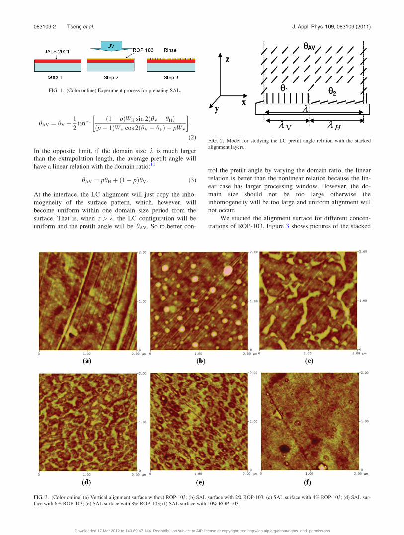
We studied the alignment surface for different concen-
trations of ROP-103. Figure 3 shows pictures of the stacked
FIG. 1. (Color online) Experiment process for preparing SAL.
FIG. 2. Model for studying the LC pretilt angle relation with the stacked
alignment layers.
FIG. 3. (Color online) (a) Vertical alignment surface without ROP-103; (b) SAL surface with 2% ROP-103; (c) SAL surface with 4% ROP-103; (d) SAL sur-
face with 6% ROP-103; (e) SAL surface with 8% ROP-103; (f) SAL surface with 10% ROP-103.
083109-2 Tseng et al. J. Appl. Phys. 109, 083109 (2011)
Downloaded 17 Mar 2012 to 143.89.47.144. Redistribution subject to AIP license or copyright; see http://jap.aip.org/about/rights_and_permissions

alignment layers using an atomic force microscopy (AFM).
From the AFM pictures, it can be calculated that the average
domain size is about 0.4 to 0.58 mm. This is a proper value
for both a linear average pretilt angle condition and a uni-
form alignment.
To verify the linear relation between the domain ratio
and average pretilt angle as indicated in Eq. (3), the domain
ratio is calculated using the AFM picture, and the pretilt
angle for anti-parallel cell with the same alignment structure
in both substrates is measured using the crystal rotation
method.27 It can be seen that the experimental result fit very
well with simulation (Fig. 4). The pretilt angle of the SAL
linearly depends on the domain ratio. Any pretilt angle
between planar and vertical alignment can be obtained by
changing the domain ratio.
Because ROP-103 is a linearly photo-polymerizable
polymer (LPP), different UV light dosage will lead to differ-
ent level of polymerization. If the UV light intensity or expo-
sure time is not enough, the ROP-103 layer may be just
partially polymerized. The unpolymerized ROP-103 material
will be rinsed away. Thus different domain ratios can be
obtained, resulting in different pretilt angles.
In our experiment, ROP-103 concentration 10% was
used. After spin-coating, the ROP-103 was exposed to UV
light for different durations. The UV lamp used here is
200 mJ=cm2 with center wavelength of 300 nm. Two sub-
strates with the same treatments were assembled in anti-par-
allel rubbing direction so that a homogeneous alignment cell
is formed. The pretilt angles were then measured. The pretilt
angles as a function of exposure time are plotted in Fig. 5. It
can be seen that it is possible to control the pretilt angle by
varying the exposure time.
III. FABRICATION OF LENS USING A UV LASER
Obviously another way to vary the UV light dosage
is by varying the light intensity with the same exposure
time. A different light intensity will lead to different po-
lymerization speeds. Thus it is possible to get spatially
variable pretilt angles by exposure to a spatially variable
UV intensity profile. A UV laser with a Gaussian profile
can therefore be used to induce spatially variable pretilt
angles.
The process for preparing the substrates is almost the
same as the previous stacked alignment layers case. The only
difference is that a UV laser is used instead of a uniform
incoherent lamp. After the SAL process, a discontinuous
ROP-103 layer is formed. In the center of the laser spot, the
pretilt angle is the smallest due to the highest polymerization
level of ROP-103. Then the top and bottom substrates were
placed in an anti-parallel rubbing direction with the vertical
alignment layer and then filled with liquid crystal (E7). The
upper substrate of the LC cell was a single vertical alignment
layer that gave high pretilt angles. The bottom substrate was
a SAL. This resulted in a hybrid aligned nematic (HAN) cell
structure.
To test the optical properties of this HAN cell, the sam-
ple was put between two crossed polarizers. The rubbing
direction of the bottom substrate is at 45� to both polarizers.
Green light at 530 nm was incident from one side of the po-
larizer and passed through the LC cell and was imaged by
a microscope camera. A 1 kHz ac voltage source was used
to drive the LC cell. The transmittance of the LC cell is
given by
T ¼ sin2 pdDn
k
� �: (4)
FIG. 4. Relation between domain ratio and average pretilt angle.
FIG. 5. (Color online) Pretilt angles as a function of exposure time. FIG. 6. (Color online) LC lens under different voltages.
083109-3 Tseng et al. J. Appl. Phys. 109, 083109 (2011)
Downloaded 17 Mar 2012 to 143.89.47.144. Redistribution subject to AIP license or copyright; see http://jap.aip.org/about/rights_and_permissions

Figure 6 shows photographs of the cell at different voltages.
The brightness of the photo represents the transmittance,
which can be used to calculate the phase retardation profile.
The retardation profile calculated in different voltages
is shown in Fig. 7. The x-axis parameter radius represents
distance to the center point. The y-axis parameter retarda-
tion is d ¼ pdDn=k. Because a parabola retardation profile
is ideal for making a lens, parabolic approximation was
made (dashed line in Fig. 7) for every retardation profile. It
can be seen that in the radius range of 0.45 mm, the retarda-
tion profile fits very well with the parabola curve in all vol-
tages. So within this area, the cell truly acts as perfect lens,
and the 0.45 mm radius circle was drawn as a red circle in
Fig. 6.
The focal length of the lens at different voltages can be
obtained by using the function:23
f ¼ r2
2dDn(5)
Where r is the radius of the LC lens, d is the LC cell thick-
ness, Dn is the effective refraction index difference between
the lens center and edge of the lens. The results are shown in
Fig. 8. It can be seen that when there is no voltage applied,
the focal length is 19 cm. The focal length is tunable from 19
cm to infinite by applying a voltage to the lens.
IV. CONCLUSION
We have demonstrated an alignment surface (SAL) that
is capable of patterning arbitrary pretilt angles spatially for a
liquid crystal layer. It is achieved by stacking two alignment
materials where the top layer is a photoalignment material.
Thus the spatial profile of the pretilt angle can be controlled
by the spatial profile of the UV source. A variable-focus liq-
uid crystal lens was achieved by SAL. The SAL layer is
quite powerful in generating any spatial pretilt angle varia-
tion. Many applications can be realized using such spatially
variable pretilt angles. For example, a beam steering device
can be made.
ACKNOWLEDGMENTS
This research was supported by the Hong Kong Govern-
ment Research Grants Council Grant No. 614410 and CERG
612409.
1P. Teixeira and T. J. Sluckin, J. Chem. Phys. 97, 1498 (1992).2J. Kim, M. Yoneya, and H. Yokoyama, Nature 420, 159 (2002).3S. Park, C. Padeste, H. Schift, J. Gobrecht, and T. Scharf, Adv. Mater. 17,
1398 (2005).4J. B. Kim, K. C. Kim, H. J. Ahn, B. H. Hwang, J. T. Kim, S. J. Jo, C. S.
Kim, H. K. Baik, C. J. Choi, and M. K. Jo, Appl. Phys. Lett. 91, 23507
(2007).5K. Zhang, N. Liu, R. J. Twieg, B. C. Auman, and P. J. Bos, Liq. Cryst. 35,
1191 (2008).6T. Z. Qian and P. Sheng, Phys. Rev. Lett. 77, 4564 (1996).7T. Z. Qian and P. Sheng, Phys. Rev. E 55, 7111 (1997).8B. Zhang, F. K. Lee, O. Tsui, and P. Sheng, Phys. Rev. Lett. 91, 215501
(2003).9O. Tsui, F. K. Lee, B. Zhang, and P. Sheng, Phys. Rev. E 69, 21704
(2004).10F. K. Lee, B. Zhang, P. Sheng, H. S. Kwok, and O. Tsui, Appl. Phys. Lett.
85, 5556 (2004).11J. Wan, O. Tsui, H. S. Kwok, and P. Sheng, Phys. Rev. E 72, 21711
(2005).12F. S. Yeung, J. Y. Ho, Y. W. Li, F. C. Xie, O. Tsui, P. Sheng, and H. S.
Kwok, Appl. Phys. Lett. 88, 51910 (2006).13F. Yeung, F. C. Xie, J. Wan, F. K. Lee, O. Tsui, P. Sheng, and H. S.
Kwok, J. Appl. Phys. 99, 124506 (2006).14F. Yeung and H. S. Kwok, Appl. Phys. Lett. 88, 63505 (2006).
FIG. 7. (Color online) Retardation pro-
file in different voltages.
FIG. 8. (Color online) Relation between voltage and focal length.
083109-4 Tseng et al. J. Appl. Phys. 109, 083109 (2011)
Downloaded 17 Mar 2012 to 143.89.47.144. Redistribution subject to AIP license or copyright; see http://jap.aip.org/about/rights_and_permissions

15J. Ho, V. G. Chigrinov, and H. S. Kwok, Appl. Phys. Lett. 90, 243506
(2007).16D. W. Berreman and W. R. Heffner, J. Appl. Phys. 52, 3032 (1981).17S. Sato, Jpn. J. Appl. Phys. 18, 1679 (1979).18H. T. Dai, Y. J. Liu, X. W. Sun, and D. Luo, Opt. Express. 17, 4317 (2009).19N. A. Riza and M. C. Dejule, Opt. Lett. 19, 1013 (1994).20A. F. Naumov, M. Y. Loktev, I. R. Guralnik, and G. Vdovin, Opt. Lett. 23,
992 (1998).
21H. Ren, Y. H. Fan, S. Gauza, and S. T. Wu, Appl. Phys. Lett. 84, 4789 (2004).22M. Ye, B. Wang, and S. Sato, Appl. Opt. 43, 6407 (2004).23H. Ren and S. T. Wu, Opt. Express 14, 11292 (2006).24H. Ren, Y. H. Lin, and S. T. Wu, Appl. Phys. Lett. 88, 191116 (2006).25M. Ye, B. Wang, T. Takahashi, and S. Sato, Opt. Rev. 14, 173 (2007).26Y. A. Nastishin, R. D. Polak, S. V. Shiyanovskii, and O. D. Lavrentovich,
Appl. Phys. Lett. 75, 202 (1999).27M. P. Cuminal and M. Brunet, Liq. Cryst. 22, 185 (1997).
083109-5 Tseng et al. J. Appl. Phys. 109, 083109 (2011)
Downloaded 17 Mar 2012 to 143.89.47.144. Redistribution subject to AIP license or copyright; see http://jap.aip.org/about/rights_and_permissions