tufline sleeved plug valves -...
TRANSCRIPT

Tufline®
SleevedPlug Valves

2
Design more economical, flexible, and compact fluid handling systems. Bi-directional flow, simple actuation, lightweight, compact design,and multiport configurations all facilitate improved system design.
Superior, longer-lasting in-line sealing. The inert PTFE sleeve completely surrounds the plug. Thesleeve provides a large, circumferential sealing surface from portto port. Open, closed, or rotating, the seal is assured. No ball orgate valve can match this sealing power.
Secure sealing with no cold-flow, deformation, orrotation of the sleeve. The sleeve is securely nestled in the valve body. High pressureribs, top and bottom retention, and 360° port lips all assuresleeve containment.
No seizing. No sticking. As the plug rotates, the 360° port lips provide a self-cleaningaction to remove scaling and adhering media.
Page / Contents
2-4 Unique and patented features
5 Multiport valves
6-11 Special application configurations
12 Pressure-temperature ratings
13 Cv factors, dimen-sions, and weights
Page / Contents
16 Manual operators and actuators
17 Actuator mounting hole configurations
18 Quick reference selection table
19 How to order
High Pressure sealing ribs
Top retention of sleeve
Sleeve relief area
No cavities. No contamination. There are no body cavities where flowmedia can accumulate and contaminatefuture processing. This cavity-freedesign also prevents sticking.
© Copyright Xomox Corporation 1965, 2006.All rights reserved. Xomox®, Tufline®. Tufline XP® and Matryx®
are registered trademarks of Xomox Corporation.Xomox XRP is a trademark of Xomox Corporation.
Bottom retentionof the sleeve
360° lips

3
Eliminate unscheduled downtime and maintenance... plus get greatly extended service life.
Many processors experience dramatic cost reductions when theyswitch from ball and gate valves.
A simple turn of the top adjustmentbolts keeps the sleeve sealing tight-ly and the valve in service far
Two independent sealing systemsprovide double protection againstatmospheric leakage.
Turn the page for detailsabout this valve’s superiordouble stem seal.
Trouble-free sealing is provided bythe large, full-circumferential PTFEsleeve. No ball or gate valve canmatch this sealing capacity.
The PTFE sleeve has a low coefficient of friction. It acts as alubricant. Ease of operation isassured, even when the valve is leftopen or closed for extended periods.
Standard cost and greatly extendedservice life assure exceptionally low,long-term cost-of-ownership.

No ball or gate valveoffers this capability.
4
The Tufline® sleeved plug valve pays foritself many times over with more up-timeand greatly extended service life.There’s a fully adjustable in-line seal and dual stem seal.
Bolts in the top cover provide quick and easy adjustment. Adjust out in-line leakage between shutdowns. Adjust out potential stem leakage.
Stem Seal 1.The primary stem seal is around thecircumference of the plug. Flowmedia is prevented from reachingthe stem. Stem Seal 2.
The secondary backup seal systemprovides a wide comprehensivebackup seal along the top edge ofthe plug and the stem.
Unmatched stem sealing. The Tufline standard dual stem sealis clearly superior to those of gatevalves, ball valves, other plugvalves, and many expensive valveswith extended auxiliary packing.
360° lips. Port defining lips were developed and patented by Tufline. The lipssurround the ports.
The lips improve valve performanceand extend service life by:
• Preventing sleeve cold flow anddeformation.
• Eliminating sleeve rotation.
• Breaking up and removingadhering, scaly deposits from theouter surface of the plug as itrotates.
There are two independent
environmental seals.
You get double seal protection
at no extra cost.
5
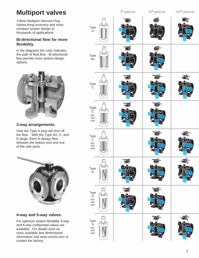
Multiport valves Tufline Multiport Sleeved PlugValves bring economy and morecompact system design to thousands of applications.
Bi-directional flow for moreflexibility. In the diagrams the color indicatesthe path of fluid flow. Bi-directionalflow permits more system designoptions.
3-way arrangements. Only the Type A plug will shut offthe flow. With the Type AX, C, and D plugs, there is always flow between the bottom port and one of the side ports.
0° position
TypeA
TypeAX
TypeC
TypeC
pos.1&2only
TypeC
pos.2&3only
TypeD
TypeD
pos.1&2only
TypeD
pos.2&3only
90° position 180° position
4-way and 5-way valves. For optimum system flexibility 4-wayand 5-way multiported valves areavailable. For details such as sizes available and dimensionalinformation visit www.xomox.com orcontact the factory.

6
Fire TestedValves
API-607 Standards. Tufline Fire Tested Sleeved PlugValves have been tested in accordance with API-607 - FourthEdition - Section 4.2 - SpecificationsFor External Leakage. Thesevalves exceed the sealing require-ments specified in those standards.A tight external seal was maintainedeven after the PTFE sleeve andsealing parts were totally destroyedby fire.
Fire tested stem seal. A metal diaphragm overlays thePTFE diaphragm. If the PTFEdiaphragm and wedge ring aredestroyed by fire, the metaldiaphragm maintains the seal.
Fire tested cover seal. In the standard valve, if the PTFEsleeve and diaphragm aredestroyed by fire, leakage wouldoccur at the cover joint. The flexiblegraphite cover seal prevents this. Itis fitted into a machined counter-bore in the valve body. The coverbolts compress the graphite ring betweenthe valve body and cover. Even iffire occurs, this seal is maintained.
Vented plug. In fire tested valves, the plug isvented on the upstream side. Thisrelieves the expansive pressurecaused by the heat of the fire.Valves with vented plugs are unidirectional. An arrow stampedon the valve body indicates the flowdirection.
Sizes: ½” - 6”.
For larger sizes use the Tertiary TopSeal shown on the next page.
Configurations: 2, 3, 4, and 5-way.Also partially and fully jacketed.
End connections:Screwed, flanged, weld.
Pressure ratings:ANSI 150, 300, and 600.
WedgeRing PTFE
Diaphragm
MetalDiaphragm
ThrustCollar
Flexible Graphite Cover Seal

7
Tertiary Top Seal Valves
Control fugitive emissions. This optional top seal package provides exceptional control of fugitive emissions. It meets orexceeds the most stringent currentregulatory requirements.
Triple sealed for extra protection. Under normal conditions, there arethree active seals between the flowmedia and the atmosphere. Primarysealing is provided by the interactionof the plug, sleeve, and body.
Secondary sealing is provided bythe PTFE and metal diaphragms.
Tertiary sealing is provided at thestem by the encapsulated, flexiblegraphite stem seal and at thebody/cover joint by the graphitecover seal ring.
This simple system assures stem sealing. This simple, compact, patenteddesign harnesses complex dynamicforces to assure effective sealing toatmosphere.
The metallic cartridge totally encapsulates the flexible graphitetertiary dynamic stem seal.
At its outer edge, the metaldiaphragm overlaps the graphitestatic seal ring to reinforce the tertiary seal at the body-to-coverjoint.
The PTFE wedge ring concentratesthe sealing force of the PTFEdiaphragm radially against the valvestem for more reliable prevention ofexternal leakage at this secondaryseal.
API-607 Standards. Like the fire tested valve, the TuflineTertiary Top Seal Sleeved Plugvalve also exceeds API-607 - FourthEdition - Section 4.2 - SpecificationsFor External Leakage. It is avail-able in a broader range of sizesthan the standard fire tested model.
Vented plug. If this valve is intended for use in a fire tested application, a vented plug is required.
Sizes: 1/2 inch - 24 inch.
Configurations: 2, 3, 4, and 5-way.Also partially and fully jacketed.
End connections:Screwed, flanged, socket weld, and butt weld.
Pressure ratings: ANSI 150, 300, and 600.
Metaldiaphragm
Valvebody
PTFEsleeve Plug
Flexible graphitecover seal
Valvecover
Cartridgeouter ring
Encapsulated, flexiblegraphite stem seal
PTFE diaphragm
Cartridge inner ring
PTFE wedge ring
Adjustingbolt

8
The cage is contained within theplug. It is fixed in place by pins thatare welded in the bottom of thevalve body. Bearings on the cageprovide clearance between the plugand the cage, so the plug rotatesfreely.
Metal-to-metal throttling. With caged plugs, there is metal-to-metal throttling and metal-to-softseat shutoff. In throttling applications, the cage protects theseat from erosion by shielding thesoft seat from direct flow impingement at the valve ports.
High velocity fluids. With high velocity fluids, the cagereduces turbulence and cuttingaction. The cage provides a moredirect, contoured flow path throughthe valve.
Sizes: 1” - 8”.
Materials:
WCB body with CD4MCu plug andcage.
316SS body with CD4MCu plug andcage.
(Other materials upon application.Consult your Tufline SalesEngineer.)
Caged PlugValves PTFE sleeve protection. Tufline Sleeved Plug Valves can befurnished with caged plugs. Thisprovides soft seat protection in throttling applications and in services with high pressure dropthrough the valve.
Typical applications: Waste sludge Calcium carbonate slurry Alum Brine Green liquor Raw river water Lime mud Sulfuric acid with zinc powderPhosphoric acid slurry Soda ash ... and many others

9
Sampling Valves
Fluid analysis, equipment evaluation, problem solving, andquality control all depend on convenient sampling.
Safe, simple sampling. 1. Valve open - normal flow.
2. As the valve is rotated and passes the intermediate position,flow is shut off. A specificamount of media is trapped within the plug. There is no trans-flow.
3. With the valve in the fully closedposition, the trapped sample canbe transferred into an appropriate container by operating sample and vent valving.
Infrequent use. In many applications, samplingvalves are cycled infrequently.Tufline Sampling Valves provideexcellent operating reliability, evenafter being left open for long periodsof time.
Tufline Sampling Valves are available in a full range of classes,sizes, and materials. You can alsochoose from several levels of fugitive emissions control.
Gravity Sampling System. Material drops from the tank or hopper into the plug cavity. Themodified plug has an opening onone side only. The plug is rotated180° and the plug contents are fedinto the gravity or vacuum systempipe.
The plug rotates 180° to its originalposition and refills. The valve canbe manually or automatically operated. A typical application ismetered injection of a pelletized orliquid catalyst.
Plug Cavity Volume - Cubic inches (approximate)
Gravity Plug Cavity Volume - Cubic inches (approximate)
1” 11/2” 2” 21/2” 3” 4” 6”
0.8 1.8 4.5 8.7 8.7 20 58
1/2” 1” 11/2” 2” 21/2” 3” 4” 6” 8”
0.2 1.3 3 7 11 11 27 64 142

10
Additional configurations Separate descriptive brochures andtechnical data are available forthese valves. Ask your SalesEngineer for details.
Severe service Tufline Severe Service Valves provide outstanding protectionagainst external leakage, even withextreme thermal cycling.
Class 600 Available in sizes 1/2” thru 24” in awide variety of materials.Multiported also available.
Tufline XP® Sleeved Plug Valveshave a patented shrink seal lip.During thermal cycling, when fugitive emissions are most likely toescape, this patented shrink-seal liptightens the seal.
To enhance protection against leakage to atmosphere, the PTFEchevron rings provide a secondary(completely redundant) pressure-assisted stem seal.
Live loaded spring washers providea constant, uniform pressure on thepacking. This is especially important during thermal cycling.
To protect the spring washers fromdamage and particle intrusion, theyare completely enclosed.
Carbon graphite filled PTFE endrings prevent extrusion of the PTFEpacking.
The primary external seal is aroundthe top of the plug.
An optional monitoring/injection portis also available.

11
Vacuum All standard Tufline valves are satisfactory for vacuum service to aslow as .01 microns of absolute pressure. However, special clean-ing is required to achieve this rating.Vacuum ratings have been established by independent laboratories by helium leak tests on mass spectrometers.
High Temperature XeniThTM sleeved plug valves pro-vide reliable shut-off in applications with temperatures up to 600° F.
Vented plugs Tufline valves are available withvented plugs on the upstream side.Venting the plug results in a unidirectional valve.
Chlorine and oxygen Cleaning, testing, drying, sealing,and packaging are all in accordancewith recommended procedures.
Bar stock Wetted surfaces of these valves areavailable in virtually any materialincluding titanium and zirconium.
Full port Full round bores, no cavities, andlips that remove adhering flowmedia all make this valve ideal forslurries, brines, muds, and sewage.Both 2-way and 3-way valves areavailable.
Product responsibility. Xomox’s concern for product performance extends to the product’s period of service. Wefeel it is important for users toalso be aware of their responsibilities. Our products aremanufactured and used in numerous applications with awide variety of service conditions. While general guidelines are often furnished, itobviously is not possible to provide complete and specificperformance data for every conceivable service condition.Therefore, the end user mustassume final responsibility forproper evaluation, application andperformance of all products. Thecontents of this document arepresented for information purposes only. Every effort hasbeen made to ensure accuracy.This information is not intendedto be construed as warranties orguarantees, expressed orimplied, nor imply use applicabili-ty, for products or servicesdescribed herein. We reservethe right to modify or improve thedesigns and specifications ofsuch products at any time withoutnotice. As the manufacturer,Xomox sells its products and services pursuant to its standardterms and conditions of sale,including its limited warranty,copies of which are availableupon request. Xomox limits its liability specifically to the replacement or repair of defective items, or to a refund forsame. Xomox does not accept liability for any incidental or consequential damages.
TM

Pressure-temperature ratings The useful range of PTFE sleevedplug valves is -20°F to +400°FTufline-475 sleeve: -20°F to +475°FTufline-600 sleeve: -20°F to +600°Fwith maximum temperature variationof 200°F.
Applications beyond these rangescan be handled effectively but mayrequire valve adjustments at theoperating temperature.
Material selections are governed bythe limits imposed by ANSI B16.34,1996 edition and B16.34a 1998 edition.
12
13
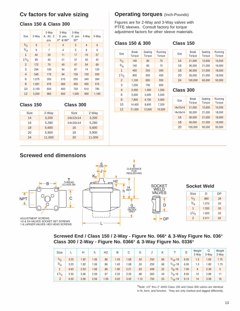
Cv factors for valve sizing
Class 150 & Class 300
Class 150 Class 300
Operating torques (Inch-Pounds)
Figures are for 2-Way and 3-Way valves withPTFE sleeves. Consult factory for torque adjustment factors for other sleeve materials.
Class 150 & 300
Screwed end dimensions
Screwed End / Class 150 / 2-Way - Figure No. 066* & 3-Way Figure No. 036*Class 300 / 2-Way - Figure No. 0366* & 3-Way Figure No. 0336*
Socket Weld
Class 150
Class 300
3-Way 3-Way 3-WaySize 2-Way A, AX, C D pos. D pos. 4-Way 5-Way
pos. 0° &180° 90°1/2 9 7 4 5 4 63/4 9 7 4 5 6 61 43 20 11 17 15 27
11/2 89 40 21 37 30 42 2 172 70 40 47 54 693 294 100 54 87 74 1204 548 175 94 159 150 2006 1,075 350 210 255 340 3908 1,591 475 360 450 455 575
10 2,159 650 450 750 610 78512 3,200 965 650 1,000 900 1,160
Size Break Seating RunningTorque Torque Torque
14x12x14 21,000 12,600 10,50014x16x14 36,000 21,000 18,000
16 36,000 21,000 18,000 18 36,000 21,000 18,00020 100,000 60,000 50,000
Size 2-Way
14 3,200
16 5,280
18 5,600
20 5,900
24 11,000
Size 2-Way
14x12x14 3,200
14x16x14 5,280
16 5,600
18 5,900
20 11,000
Size Break Seating RunningTorque Torque Torque
14 21,000 12,600 10,50016 36,000 21,000 18,00018 36,000 21,000 18,00020 36,000 21,000 18,00024 100,000 60,000 50,000
Size Break Seating RunningTorque Torque Torque
1/2 140 80 70 3/4 140 80 701 400 250 200
11/2 800 500 4002 1,100 650 5503 1,200 700 6004 2,400 1,450 1,2006 5,000 3,000 2,5008 7,800 4,700 3,900 10 14,400 8,600 7,20012 21,000 12,600 10,500
Size D DP1/2 .860 .383/4 1.070 .50 1 1.335 .50
11/2 1.920 .50 2 2.411 .63
Size L H h H2 B C S J K T E Weight G Weight2-Way 3-Way 3-Way
1/2 3.25 1.92 1.06 .86 1.43 1.68 .50 .250 .66 5/16-18 6.00 1.5 1.69 1.753/4 3.25 1.92 1.06 .86 1.43 1.68 .50 .250 .66 5/16-18 6.00 1.5 1.80 1.751 4.63 2.50 1.66 .86 1.90 2.21 .63 .438 .32 3/8-16 7.00 4 2.38 5
11/2 5.50 3.06 2.09 .97 2.33 2.33 .88 .563 .44 3/8-16 8.00 10 2.88 112 6.50 3.56 2.56 1.00 3.02 3.02 1.13 .750 .53 7/16-14 9.13 14 3.38 16
*Note: 1/2” thru 2” ANSI Class 150 and Class 300 valves are identicalin fit, form, and function. They are only marked and tagged differently.

14
Dimensions
Flanged End / Class 150 / 2-Way - Figure No. 067 & 3-Way Figure No. 037
* On 8” valves, the two top holes in the flange are tapped for 3/4-10UNC-2B threads.
On 10” and 12” valves, the two top holes in the flange are tapped for 7/8-9UNC-2B threads.
On 14” valves, the two top holes in the flange are tapped for 1-8UNC-2B threads.
On 24” valves, the top six holes in the flange are tapped for 11/4-8UNC-2B threads.
† 21/2” valves are machined from 3” castings, but the flanges are machined to 21/2” dimensions.
Dimensions are in inches. Weights are in pounds.
Size L H D T P R N O C S J K E Z CX Weight G Weight2-Way 3-Way 3-Way
1/2 4.25 1.92 3.50 .38 1.38 1.75 4 .63 2.38 .50 .250 .66 6.00 - 1.09 2.8 2.75 3.83/4 4.63 1.92 3.88 .41 1.69 1.94 4 .63 2.75 .50 .250 .66 6.00 - 1.09 3.3 2.88 4.51 5.00 2.50 4.25 .44 2.00 2.13 4 .63 3.13 .63 .438 .32 7.00 .53 1.38 6.5 3.50 9
11/2 6.50 3.06 5.00 .56 2.88 2.50 4 .63 3.88 .88 .563 .44 8.00 .59 1.56 13 4.13 172 7.00 3.56 6.00 .63 3.63 3.00 4 .75 4.75 1.13 .750 .53 9.13 .78 2.00 20 4.50 26
21/2† 8.00 4.13 7.50 .75 4.13 3.75 4 .75 5.50 1.13 .750 .53 10.13 .78 2.00 31 5.13 423 8.00 4.13 7.50 .75 5.00 3.75 4 .75 6.00 1.13 .750 .53 10.13 .78 2.00 31 5.13 424 9.00 5.22 9.00 .94 6.19 4.63 8 .75 7.50 1.25 .875 .78 22.00 .90 2.50 54 6.00 696 10.50 7.35 11.00 1.00 8.50 5.50 8 .88 9.50 2.00 1.398 1.00 25.00 - 3.06 95 7.50 1198 11.50 9.32 13.50 1.13 10.63 6.75 8 .88* 11.75 2.00 1.398 1.00 28.00 - 4.12 175 9.00 214
10 13.00 10.81 16.00 1.19 12.75 8.00 12 1.00* 14.25 2.50 1.673 1.00 29.00 - 4.50 260 11.00 33112 14.00 11.81 19.00 1.25 15.00 9.50 12 1.00* 17.00 3.00 1.968 1.00 35.00 - 5.31 355 - -14 15.00 11.75 21.00 1.38 16.25 10.50 12 1.13* 18.75 2.97 1.968 .995 N/A - 5.31 430 - -16 30.00 14.96 23.50 2.12 18.50 11.50 16 1.13 21.25 3.94 2.00 1.575 N/A - N/A 925 - -18 33.00 14.96 25.50 2.25 21.00 12.75 16 1.25 22.75 3.94 2.00 1.575 N/A - N/A 1,005 - -20 36.00 14.96 27.50 2.38 23.00 14.00 20 1.25 25.00 3.937 2.00 1.575 N/A - N/A 1,200 - -24 39.00 20.48 32.00 2.50 27.25 16.13 20 1.38* 29.50 6.00 4.00 2.000 N/A - N/A 2,500 - -

15
Flanged End / Class 300 / 2-Way - Figure No. 0367 & 3-Way Figure No. 0337
* On 14" valves, the two top holes in the flanges are tapped for 1-8UNC-2B threads.
** On 20" valves the six top holes in the flanges are tapped for 11/4 -8 unc-2B threads.† 21/2" valves are machined from 3" castings, but the flanges are machined to 21/2" dimensions.
Dimensions are in inches. Weights are in pounds.
Wrench & Enclosed Gear Operator Dimensions These operator dimensions apply to all flange types and all multiport valves.
Size L H D T P R N O C S J K E Z CX Weight G Weight2-Way 3-Way 3-Way
1/2 5.50 1.92 3.75 .56 1.38 1.88 4 .63 2.63 .50 .250 .66 6.00 - 1.09 6 2.88 83/4 6.00 1.92 4.63 .63 1.69 2.31 4 .75 3.25 .50 .250 .66 6.00 - 1.09 9 3.00 121 6.50 2.50 4.88 .69 2.00 2.44 4 .75 3.50 .63 .438 .32 7.00 .53 1.38 11 3.75 15
11/2 7.50 3.06 6.13 .81 2.88 3.06 4 .88 4.50 .88 .563 .44 8.00 .59 1.56 21 4.38 29 2 8.50 3.56 6.50 .88 3.63 3.25 8 .75 5.00 1.13 .750 .53 9.13 .78 2.00 28 4.75 37
21/2† 11.13 4.13 8.25 1.13 4.13 4.13 8 .88 5.88 1.13 .750 .53 10.13 .78 2.00 38 5.56 533 11.13 4.13 8.25 1.13 5.00 4.13 8 .88 6.63 1.13 .750 .53 10.13 .78 2.00 38 5.56 53 4 12.00 5.22 10.00 1.25 6.19 5.13 8 .88 7.88 1.25 .875 .78 22.00 .90 2.50 80 6.75 105 6 15.88 7.35 12.50 1.44 8.50 6.25 12 .88 10.63 2.00 1.398 1.00 25.00 - 3.06 165 8.50 2078 16.50 9.32 15.00 1.63 10.63 7.50 12 1.00 13.00 2.00 1.398 1.00 28.00 - 4.12 267 10.00 334
10 18.00 10.81 17.50 1.88 12.75 8.75 l6 1.13 15.25 2.50 1.673 1.00 29.00 - 4.50 395 12.00 47012 19.75 11.81 20.50 2.00 15.00 10.25 16 1.25 17.75 3.00 1.968 1.00 35.00 - 5.31 540 - -14 30.00 14.96 23.00 2.12 16.25 11.50 20 1.25* 20.25 3.937 2.00 1.575 N/A - N/A 925 - -16 33.00 14.96 25.50 2.25 18.50 12.75 20 1.38 22.50 3.937 2.00 1.575 N/A - N/A 1,005 - -18 36.00 14.96 28.00 2.38 21.00 14.00 24 1.38 24.75 3.937 2.00 1.575 N/A - N/A 1,200 - -20 39.00 20.48 32.00 2.50 23.00 16.13 24 1.38** 27.00 6.00 4.00 2.00 N/A - N/A 2,500 -
Size M B Y 1/2 - 4.00 6.38 3/4 - 4.00 6.381 3.81 2.88 8.75
11/2 4.56 3.63 12.502 5.13 4.00 18.00
21/2 5.69 4.63 24.003 5.69 4.63 24.004 7.06 5.75 30.00
Size F G U V
4 8.75 6.00 2.06 8.006 11.50 9.00 2.62 10.388 13.50 9.00 2.62 10.3810 15.25 12.00 3.53 12.3112 16.25 15.00 4.88 15.8814 21.66 15.00 5.38 16.9016 21.66 12.00 5.12 17.6618 21.66 12.00 5.12 17.6620 32.92 15.75 16.97 24.0024 32.92 15.75 16.97 24.00

16
ManualOperators A wide variety of handle and gearoperators are available.
You can choose from chain wrenches, T-wrenches, chainwheels, and tandem adapters.
Talk with your Tufline Sales Engineer about your specificrequirements, sizing, and how toorder.
Xomox XRP™Actuators The unique features of Xomox XRPPneumatic Rack & Pinion Actuatorsinclude:
* A balanced pinion which doesnot require an external retainingclip to prevent the pinion fromblowing out.
* Individual single point adjustmentfor both the CW and CCW directions.
* 98 degrees of total travel on themost popular sizes.
* Vertically aligned air passagesallow increased air flow minimizing cycle time.
Xomox Limit Switches A wide variety of switching optionsand other automation accessoriesare available.
Matryx® Vane Actuators Matryx Vane Actuators provide reliable and efficient remote controlof any type of rotary operation.They are used for ball, plug, andbutterfly valves as well as othermechanisms such as dampers,switches, and safety devices. Theyare available up to 30,000 in-lbs oftorque.
Locking DevicesSpecify whether the valve is to belocked open, closed, or both. (The lock is not supplied.)
Xomox Actuators – Automation Accessories

Size A AY W X A W X 1/2 - - - - 3.62 5/16-18 .473/4 - - - - 3.75 5/16-18 .47
1 4.19 1.75 5/16-18 .38 - - -
11/2 5.75 1.75 5/16-18 .47 - - -
2 6.31 2.25 5/16-18 .47 - - -
21/2 7.13 3.50 3/8-16 .56 - - -
3 7.13 3.50 3/8-16 .56 - - -
4 8.00 4.00 7/16-14 .63 - - -
6 9.44 4.00 7/16-14 .63 - - -
8 10.19 6.00 1/2-13 .63 - - -
10 11.56 6.00 1/2-13 .63 - - -
12 12.53 6.00 1/2-13 .63 - - -
14 13.750 6.00 1/2-13 .63 - - -
16 27.812 8.00 5/8-11 1.00 - - -
18 30.688 8.00 5/8-11 1.00 - - -
20 33.56 8.00 5/8-11 1.00 - - -
24 36.25 11.50 1.00-8 1.50 - - -
17
Actuator mounting hole configurations Full dimensions for valve and actuator assemblies are available.
Class 150 4 hole pattern 2 hole pattern
Dimensions are in inches.
Size A AY W X A W X1/2 - - - - 4.38 5/16-18 .473/4 - - - - 4.38 5/16-18 .47
1 5.75 1.75 5/16-18 .38 - - -
11/2 6.63 1.75 5/16-18 .47 - - -
2 7.56 2.25 5/16-18 .47 - - -
21/2 9.94 3.50 3/8-16 .56 - - -
3 9.94 3.50 3/8-16 .56 - - -
4 10.69 4.00 7/16-14 .63 - - -
6 14.00 4.00 7/16-14 .63 - - -
8 14.63 6.00 1/2-13 .63 - - -
10 15.69 6.00 1/2-13 .63 - - -
12 17.38 6.00 1/2-13 .63 - - -
14 27.812 8.00 5/8-11 1.00 - - -
16 30.688 8.00 5/8-11 1.00 - - -
18 33.563 8.00 5/8-11 1.00 - - -
20 36.25 11.50 1.00-8 1.50 - - -
Class 300 4 hole pattern 2 hole pattern

18
Quick Reference Selection Table The table below provides a brief overview of the most commonly specified valves. When ordering, be sure to specifyall options including body, plug, and sleeve materials.
No. of Type* ANSI Size Operator FigurePorts Class Range Number
Screwed End150
1/2-2066
300 Wrench 0366
1501/2-4 067
Flanged End4-24 Enclosed Gear 067EG
3001/2-4 Wrench 0367
4-24 Enclosed Gear 0367EG
2 1501-4 Wrench 067PJ
Partial Jacket4-12 Enclosed Gear 067PJ-EG
3001-4 Wrench 0367PJ
4-12 Enclosed Gear 0367PJ-EG
1502x1x2-6x4x6 Wrench 067FJ
Full Jacket6x4x6-12x10x12 Enclosed Gear 067FJ-EG
3002x1x2-6x4x6 Wrench 0367FJ
6x4x6-12x10x12 Enclosed Gear 0367FJ-EG
Screwed End150 1/2-2 036
300 1/2-2 Wrench 0336
1501/2-4 037
Flanged End4-12 Enclosed Gear 037EG
3 3001/2-4 Wrench 0337
4-12 Enclosed Gear 0337EG
1501-4 Wrench 037PJ
Partial Jacket4-8 Enclosed Gear 037PJ-EG
3001-4 Wrench 0337PJ
4-8 Enclosed Gear 0337PJ-EG
Screwed End 1/2-2Wrench
046
4 Flanged End 1/2-4 047
Flanged End 150 6-12 Enclosed Gear 047-EG
5Screwed End 1/2-2
Wrench056
Flanged End 1-4 057
* Socket weld and butt weld end valve information is available in a separate catalog.
Notes
2-way Tufline Sleeved Plug Valves provide
tight shutoff from high vacuum through rated
pressure at temperaturesfrom -20°F to 600°F
Standard jacketed valvesare available in carbon
steel or 316 stainless steel.
All jackets are rated at 235psi at 400°F.
Full jacketed valves haveover-sized flanges.
When ordering 3-wayvalves, be sure to include
the port configuration. Refer to page 5.
Bodies are available in carbon steel or 316
stainless steel. Standardpressure/temperature ratingsapply, with the exception that
pressure drop should notexceed 170 psi at 100°F
when switching.

1” - 066 - FT - 6 - 6 - P1 - W - C
19
Materials The following are ASTM designations formaterials listed elsewhere in this catalog.
Carbon steel . . . . . . . . .ASTM A216 WCB
302 stainless steel . . . .ASTM A240 Type 302
304 stainless steel . . . .ASTM A240 Type 304
304 stainless steel . . . .ASTM A351 CF8
304L stainless steel . . .ASTM A351 CF3
316 stainless steel . . . .ASTM A351 CF8M
316L stainless steel . . .ASTM A351 CF3M
Alloy 20 . . . . . . . . . . . .ASTM A351 CN7M
Bronze . . . . . . . . . . . . .ASTM B61
CD4MCu . . . . . . . . . . .ASTM A351 CD4MCu
Ductile Iron . . . . . . . . . .ASTM A395
Hastelloy B . . . . . . . . . .ASTM A494 N7M
Hastelloy C . . . . . . . . . .ASTM A494 CW6M
Inconel . . . . . . . . . . . . .ASTM A494 CY40
Nickel . . . . . . . . . . . . . .ASTM A494 CZ-100
Monel . . . . . . . . . . . . . .ASTM A494 M30-C
Ni-Al Bronze . . . . . . . . .ASTM B148 Gr.958
Titanium . . . . . . . . . . . .ASTM B367 Gr. C-3
Zirconium . . . . . . . . . . .ASTM B752 Gr. 702
Other ferrous and non-ferrous materials areavailable upon application.
Size & Figure No. See Quick ReferenceSelection Table on theprevious page
Options Fire Tested . . . . . . .FTTertiary Top Seal . .TSCage Control . . . .CCVExtended Packing .XPPartial Jacket . . . . .PJFull Jacket . . . . . . .FJPort Arrangements for 3-Way valves (See page 6) . . . . . .A, AX, C, or D
Valve specificationsmay include multipleoptions.
Body Alloy 20 . . . . . . . . . . .0Ductile Iron . . . . . . . .1Carbon Steel . . . . . .2Monel . . . . . . . . . . . .3Nickel . . . . . . . . . . . .5316SS . . . . . . . . . . . .6Hastelloy B . . . . . . . .8Hastelloy C . . . . . . . .9CD4MCu . . . . . . . . .27lnconel . . . . . . . . . .40Other (Specify) . . . . .X
ServiceChlorine . . . . . . .COxygen . . . . . . . .OVacuum . . . . . . . .VGeneralService . . . .BlankOther** . . . . . . . .X
OperatorLess Operator . . .NWrench . . . . . . .WWrench with locking device .WYGear . . . . . . . . . .GGear with locking device .GZActuator* . . . . . . .A
SleevePTFE . . . . . . . . .P115% RPTFE . . .P225% RPTFE . . .P3PFA . . . . . . . . . .P6Xomox-7 . . . . . .P7UHMWPE . . . . .P8Tufline-475 . . .P16Tufline-600 . . .P20Other(Specify) . . . . . .PX
PlugAlloy 20 . . . . . . . .0Ductile Iron . . . . .1Carbon Steel . . . .2Monel . . . . . . . . .3304SS . . . . . . . . .4Nickel . . . . . . . . .5316SS . . . . . . . . .6Hastelloy B . . . . .8Hastelloy C . . . . .9CD4MCu . . . . . .27Inconel . . . . . . . .40Other (Specify) . .X
How to specify
Size Figure
No.
Option
Body
Plug Sleeve
Opera
tor
Servic
e
* Specify actuator type and available air supply.
** Consult your Xomox SalesEngineer for a wide variety ofother available service options.

Global Capabilities For Global Customers
Worldwide capabilities. No matter where in the world youare, Xomox technical support andservices are available from:
• 16 Manufacturing Facilities
• 18 Service Centers
• 50 Sales Offices
• More than 200 XomoxAuthorized Distributors
Product selection. Xomox offers the broadest line ofprocess valves, actuators, accessories, and related servicesincluding:
• Tufline Process Valves
• Saunders Diaphragm Valves
• Matryx Rack & Pinion, VaneActuators
• Xomox XRP™ Actuators
Corporate strength. Xomox is a Crane Co. company.Through the Crane Co. association,Xomox offers even greater globalcapabilities and breadth of productlines.
Xomox Corporation World Headquarters 4444 Cooper Road Cincinnati, Ohio 45242
Global locator. For a listing of XomoxManufacturing Facilities, ServiceCenters, Regional Offices, andAuthorized Distributors, visit ourweb site www.xomox.com
Xomox literature. All Xomox catalogs and technicaldata are available as PDF files atwww.xomox.com
Phone support. Call your nearest Xomox SalesOffice or the Xomox WorldHeadquarters: Phone: 513-745-6000 Fax: 513-745-6093
PN329703 04/06 3M C&O