tubular web rbs connection to improve seismic behavior of
TRANSCRIPT
Scientia Iranica A (2017) 24(6), 2726{2740
Sharif University of TechnologyScientia Iranica
Transactions A: Civil Engineeringwww.scientiairanica.com
Tubular Web RBS connection to improve seismicbehavior of moment-resisting steel frames
S.M. Zahraia, S.R. Mirghaderia and A. Salehb;�
a. School of Civil Engineering, College of Engineering, The University of Tehran, Tehran, P.O. Box 11155/4563, Iran.b. Department of Civil Engineering, Islamic Azad University, Professor Hesabi Branch, Tafresh, P.O. Box 3951736167, Iran.
Received 17 October 2015; received in revised form 29 June 2016; accepted 29 October 2016
KEYWORDSCyclic behavior;Moment-resisting steelframes;Rigid connection;Reduced beamsection;Tubular Web RBS(TW-RBS).
Abstract. A new type of Reduced Beam Section (RBS) connection, called \Tubular WebRBS (TW-RBS)", is proposed in this research. TW-RBS is made by replacing a part of webwith a tube at the expected location of the beam plastic hinge. In addition to an analyticalstudy, the proposed section is numerically studied under cyclic load using ABAQUS �nite-element software, and a test specimen is used for the calibration of numerical results.The results show that using TW-RBS not only creates a ductile fuse far from the beam-to-column connection components, but it also increases story drift capacity up to 9%.Furthermore, the tubular web, like corrugated sheet, can improve both the out-of-planesti�ness of the beam longitudinal axis and the ange stability condition due to the smallerwidth-to-thickness ratio of the beam ange in the plastic hinge region. Thus, the tubularweb improves lateral-torsional buckling stability of beam. On the other hand, the tubularweb provides a better condition than other accordion web with sharp corners in terms oflow-cycle fatigue, because change of direction of strain in arc shape of the tubular websection is smaller than the accordion web with sharp corners.
© 2017 Sharif University of Technology. All rights reserved.
1. Introduction
The experiences gained from the earthquake e�ects,such as the Northridge and Kobe earthquakes, posedserious challenges in seismic behavior of steel structuresat the international level. The most extensive studyhas been done by the SAC committee leading to theresults published in the set of FEMA 350 [1]. Theconcentrated tensions on the welded areas of ange,web, and connection vulnerability in high ductilitydemands were considered as two main critical factors
*. Corresponding author. Tel./Fax: +98 21 6111-2273E-mail addresses: [email protected] (S.M. Zahrai);[email protected] (S.R. Mirghaderi);[email protected] (A. Saleh)
doi: 10.24200/sci.2017.4168
of failure. A common way to resolve this issue is toreduce the ductility demand and related concentratedtensions in these areas. Thus, di�erent methodsand ideas have been provided in order to reduce thedemands of the beam-to-column connection. A basicstrategy of this method is to intentionally reduce thesection of the connected beam which results in theformation of plastic hinge at the reduced cross-section.Furthermore, local reduction decreases the demand ofthe components of connection. It reduces the damagesmade to the components of connection including panelzone, continuity plates, and related welds at a rigidconnection. The studies on the reduced beam sectioncan be categorized as follows:
1.1. RBS connectionsRBS connection with a dog-bone con�guration was

S.M. Zahrai et al./Scientia Iranica, Transactions A: Civil Engineering 24 (2017) 2726{2740 2727
initiated by a European company, named Arbed, andwas patented in the USA in 1992. SAC committee [2]studied the results of 45 tests on RBS connectionafter the Northridge Earthquake during 1996 to 1998.The main variables in these tests are the shape of ange cut (straight cut, tapered cut, or radius cut),depths of columns and beams, and web connection.According to the results, the radius cut RBS connectionshowed successful behavior; the connection behaviordepended on the beam depth; bolted and welded webconnections had relatively similar behaviors. Chen andChao (2001) [3] examined the e�ects of concrete slabon moment connection by the reduced section. Theyshowed that the ratio of positive to negative momentcapacity can be 1.18 with the presence of slab.
Adopting a statistical study, cyclic instability ofRBS connections was investigated by Uang and Fanin 2001 [4]. Nakashima and Kanao (2002) [5] studiedanalytically and numerically the lateral torsional in-stability and lateral bracing e�ects of wide- ange steelbeams subjected to cyclic loading. Jay Shen et al.(2002) [6] analyzed the RBS connected to deep columnsand investigated the e�ects of slab through a numericalapproach. This study showed that the lateral beamsand oor slab provide suitable lateral bearing for thebeam.
Jones et al. (2002) [7] experimentally investigatedthe e�ects of panel zone, concrete slab, and also thee�ect of the web connection type. Roeder (2002) [8],summarizing SAC committee's research, expressed thatdevelopment of shear deformation in panel zone inthe RBS connections can also enhance the ductilitydemand on the column ange weld. Ricles et al.(2002) [9] presented that panel zone in the RBSconnections plays an important role in connectionbehavior provided for using balanced panel zone in ananalytical and experimental research report. Lee etal., 2005 [10], using eight full-scale tests, showed thatstrong panel zone leads to dissipating total energy inthe reduced region; so, this area has signi�cant localbuckling and lateral-torsional buckling which leads toa twisted column.
Moslehi Tabar and Deilami (2005) [11] numeri-cally studied the instability of RBS connection, con-centrating on the e�ect of plasticity shear panel incolumns. Their results indicated that not only doesthe rigid shear panel keep the panel zone in theelastic range, but it also causes instability in thebeam cyclic behavior. Zhang and Ricles (2006) [12,13]demonstrated that concrete oor supports beam top ange and increases the ultimate load in the plastichinge, which is not included in design procedures. Hanand Moon (2009) [14] showed that if the span-to-depthratio is less than 10 and if the beam ange bending-moment contribution is less than 70% of the beam exural strength, then using web bolted connection is
not recommended. Pachoumis et al. (2010) [15] studiedcyclic behavior of RBS moment connections throughexperimental and numerical analysis. They showedthat using the RBS connection in European sectionsrequires changing the RBS geometric parameters.
1.2. Reducing the web heightIn another study, Wilkinson et al. (2006) [16] evaluateda new detail by which the web height reduction nearthe connection of beam-to-column is achieved. Theexperimental results approved that the plastic rotationcapacity is more than 5%.
1.3. Connection with web reductionIn FEMA 350 [1], a new type of reduced connectionhas been proposed in which the demand reductionat the column face is provided through making acircle hole in the web near the connection. Thesize of hole is such that the yielding occurs alongthe span and the connection remains in the elasticrange. Rao and Kumar (2006) [17] studied a connectionwith rectangular hollow in web, entitled RectangularHollow Sections (RHS). In their study, channel beam tochannel column connection was used. Yang and Yang(2009) [18] studied the circular hole in web sections aswell as a built-up beam numerical model with di�erentloading distances of 2, 3, 4, and 5 meters and varyingcircular holes radius.
1.4. Connection with accordion webThe exural behavior of a beam with corrugated webconsiderably di�ers from that with a at web. This dif-ferent behavior is derived from the di�erence betweenthe natures of the at sheet and corrugated sheet. Flatsheet in the in-plane stress has an isotropic behavior,although sti�ness of corrugated sheet in x and ydirections is completely di�erent. In the longitudinaldirection, sti�ness is sharply reduced. This smallsti�ness in corrugated sheet causing deformation underload is similar to opening and closing accordion. Thisbehavior is called accordion behavior. So, by usingaccordion web in beams due to the lack of strain on theweb, and thereby little participation of corrugated webin exure resistance, the ultimate bending capacity canbe determined only based on the beam ange plasticcapacity while web e�ect can be ignored. In this case,the whole shear is mainly tolerated by the corrugatedweb. Previous studies have also shown that there is nointeraction between the exural behavior and shear be-havior of beams with corrugated web [19]. Mirghaderiet al. (2010) [20] discussed and evaluated bendingbeam connection of reduced cross-section by corrugatedweb in an experimental and analytical study. Twosymmetric angles were considered in two test sampleswith respect to the web as corrugated sheet to executeremoved web accommodation and create a cross-sectionas Accordion Web RBS (AW-RBS). The results of both

2728 S.M. Zahrai et al./Scientia Iranica, Transactions A: Civil Engineering 24 (2017) 2726{2740
tests were correlated without reducing resistance up to8% story drift. Saleh et al. (2016) [21] experimentallystudied a kind of accordion-web RBS connection inwhich part of the at web of the beam is replaced bya steel tube. Based on the experimental results, thetubular web in the plastic hinge region improves lateral-torsional buckling stability of the beam, such that onlylocal buckling of the beam ange at the center of thereduced section was observed during the tests.
1.5. Heat-treated Beam Section (HBS)The technique involves reducing the strength of spec-i�ed regions of the beam anges by exposing themto high temperatures followed by slow cooling asstudied by Morrison et al. (2015) [22]. Contraryto RBS, HBS connection does not sacri�ce elasticsti�ness or buckling resistance. They tested two large-scale connections modi�ed with the HBS techniqueleading to the promotion of yielding and plastic hingedevelopment in the heat-treated regions with specimensattaining inter-story drifts as high as 6% without weldor near-weld fracture.
Usual RBS moment connection is one of the mosteconomical and practical prequali�ed connections, butaccording to the previous studies, this connection isweak in terms of assessing beam instabilities, such asweb and ange local buckling and subsequent lateraltorsional buckling. Such instabilities cause degradationin the connection strength at large rotation demands.On the other hand, beam connection with a reductionin web area or web height reduces shear strength atthe plastic hinge location. Heat-treated beam section isbetter than the other purposed connections, but seemsexpensive as heat processing is used after fabrication.Connection with accordion web can improve both out-of-plane sti�ness of the beam longitudinal axis and the ange stability condition due to the smaller width-to-thickness ratio of beam ange. Thus, conditionsof beam stability would be better in connection withaccordion web at larger rotation demands.
Parallel to the connection with accordion web inthis paper, a new web RBS connection called \TW-RBS" is proposed for steel moment-resisting frames. Inthe proposed connection, the beam bending capacityis reduced using a pipe instead of a at web atthe expected location of the beam plastic hinge inthe vicinity of the beam-to-column connection. Thetubular web provides even a better condition thanAW-RBS connection in low-cycle fatigue by changingsharp corners of angles to arc shape of the tubularweb section. In this regard, the present study aimsto analytically and numerically investigate the seismicbehavior and cyclic response of the new proposedconnection. It is noteworthy that a specimen test wasused for the calibration of numerical results in thisstudy.
2. The proposed connection (TW-RBS) design
2.1. Determining the appropriate location ofthe TW-RBS
Connection design approach is based on the 2010 AISCseismic provisions [23]. In order to reduce demandand decrease the failure of beam welded to columnconnection and surrounding material, the maximummoment demand at the column face must be lowerthan the nominal plastic strength in that speci�c point.Therefore, as illustrated in Figure 1, the maximummoment generated at the column face (Mf ) can beobtained from the image of the maximum expectedmoment established in the center of the reduced beamsection (MTW-RBS) as follows:
Mf = MTW-RBS(L+ e)L
; (1)
where L is the distance between the centerline ofreduced beam section to the middle span. If comparedto the seismic demand, the gravity load on the beamis assumed small, and then the moment distributionis linear. Maximum expected moment created in thecenter of reduced beam section (MTW-RBS) based onseismic criteria is de�ned as follows:
M(TW-RBS) = 1:1RyZ(TW-RBS)Fy; (2)
where ZTW-RBS is the plastic section modulus of thecorrugated region, and Ry is the di�erence betweenthe minimum speci�ed yield strength (Fy) and theexpected yield strength. Maximum moment demand atthe column face ratio to the nominal plastic strengthis calculated as follows:
Figure 1. Bending moment gradient for seismic loading.

S.M. Zahrai et al./Scientia Iranica, Transactions A: Civil Engineering 24 (2017) 2726{2740 2729
� =Mf
ZbRyFy=M(TW-RBS)
(L+e)L
ZbRyFy
=1:1RyZ(TW-RBS)Fy
(L+e)L
ZbRyFy
=1:1Z(TW-RBS)(L+ e)
ZbL: (3)
In the equation above, Zb is the plastic modulus in theunreduced beam section at the column face. In orderto reduce demand and failure risk in welded connectionof beam and the column face, the value of � mustbe lower than 1. The recommended value for thisparameter in the design of common reduced beams is0.9 [24]. Therefore, the plastic modulus of reduced andunreduced beam sections and the length of cantileveredbeam (L+ e) determine the appropriate distance fromthe center of the reduced section to the column face.
2.2. Substructure and the choice ofdimensional parameters
The proposed subassembly used in similar experimen-tal studies investigated by Mirghaderi et al. [20] waschosen to con�rm bene�cial behavior of the connection.It consists of interior connection with beams attachedto the column opposite faces. In this subassembly, halfof the parts of lower and upper columns were chosen asvertical elements, and half of the beam was chosen ashorizontal elements.
For modeling the connection, box-column (built-
up 200�160�10) and IPE180 were chosen, respectively,for column and beam, as shown in Table 1. Thegeometrical dimensions are 2150 mm for the verticalmembers, acting as the columns, and 3290 mm (dis-tance between the rollers boundary condition of twobeams) for the horizontal members, behaving as thebeams. The selected sections satisfy width-thicknessratio of seismically compact section.
The distance of center of tube to the column faceand also diameter of tube come from Table 2 andEq. (4):
As it can be seen, with considering the allowedrange for e, the diameter of tube can be determinedfrom Eq. (4):
D = 2(e� a): (4)
So, by allowing for a = 5:35, it gives a value of7.3 cm for tube outside the diameter. The thicknessof available steel pipe in the market according to DIN-2440 is 5.5 mm, which is known with nominal diameterof 65 mm (2-1/2 inch).
2.3. Determining the expected moment inplastic hinge location (MTW-RBS)
According to the reduced section plastic modulus, theexpected moment is speci�ed in the beam plastic hingelocation and the condition of weak beam-strong columnis controlled, as presented in Table 3 in which expectedyielding stress of material (Fye = RyFy = 1:5�2400 =3600) has been used. Su�cient safety factor for columnface demand is provided (� = 0:888).
Table 1. Determining the beam and column speci�cations.
Member Section A(m2 � 10�4)
d(m�10�2)
bf(m�10�2)
tf(m�10�2)
tw(m�10�2)
Beam IPE180 23.9 18 9.1 0.8 0.53Column 200� 160� 10 64.0 18 14 1.0 1.0
Note: A: cross-section area; d: depth of section; bf and tf : width and thickness of ange; and tw: thickness of web.
Table 2. Determining the reduced section of dimensional parameters.
Section Zb(m3 � 10�6)
ZTW-RBS
(m3 � 10�6)L+ e
(m�10�2)e
(m�10�2)
Allowed range of e0:5d < e < d(m�10�2)
Allowed range of a0:5bf < a < 0:75bf
(m�10�2)IPE180 166 131.44 154.5 9 9 < e < 18 4:55 < a < 6:83
Note: Zb: Plastic modulus of the unreduced section; ZTW-RBS: Plastic modulus of the reduced section (Appendix);L+ e: Length of beam; and e: Distance from the center of the reduced section to the column face (Eq. (3)).
Table 3. Beam design control at the column face.
ZTW-RBS
(m3 � 10�6)MTW-RBS
(kN-m)L
(m�10�2)e
(m�10�2)Mf
(kN-m)ZbFye
(kN-m)� e+ dc=2
(m�10�2)
PMpb
(kN-m)
PMpc
(kN-m)PMpc=
PMpb
131.44 52.05 145.5 9 55.27 59.76 0.925 19 117.7 205.44 1.75Note: MTW-RBS: expected moment in plastic hinge location; Mf : beam moment at the column face location;� = Mf=ZbFye: moment ratio at the column face;PMpb =
PMc = 2Mf � (L+ e+ dc=2)=(L+ e): beam moment at the center of column;P
Mpc =PZcFyc: column plastic moment.
2730 S.M. Zahrai et al./Scientia Iranica, Transactions A: Civil Engineering 24 (2017) 2726{2740
2.4. Controlling beam shearIn corrugated sheets, shear buckling is controlled bythe interaction of the buckling mode obtained frominteraction of local and global buckling modes. Elasticlocal buckling shear stress can be calculated usingEq. (5) [25]:
�ecr;l = k1�2E
12(1� �2)
�tw!
�2
: (5)
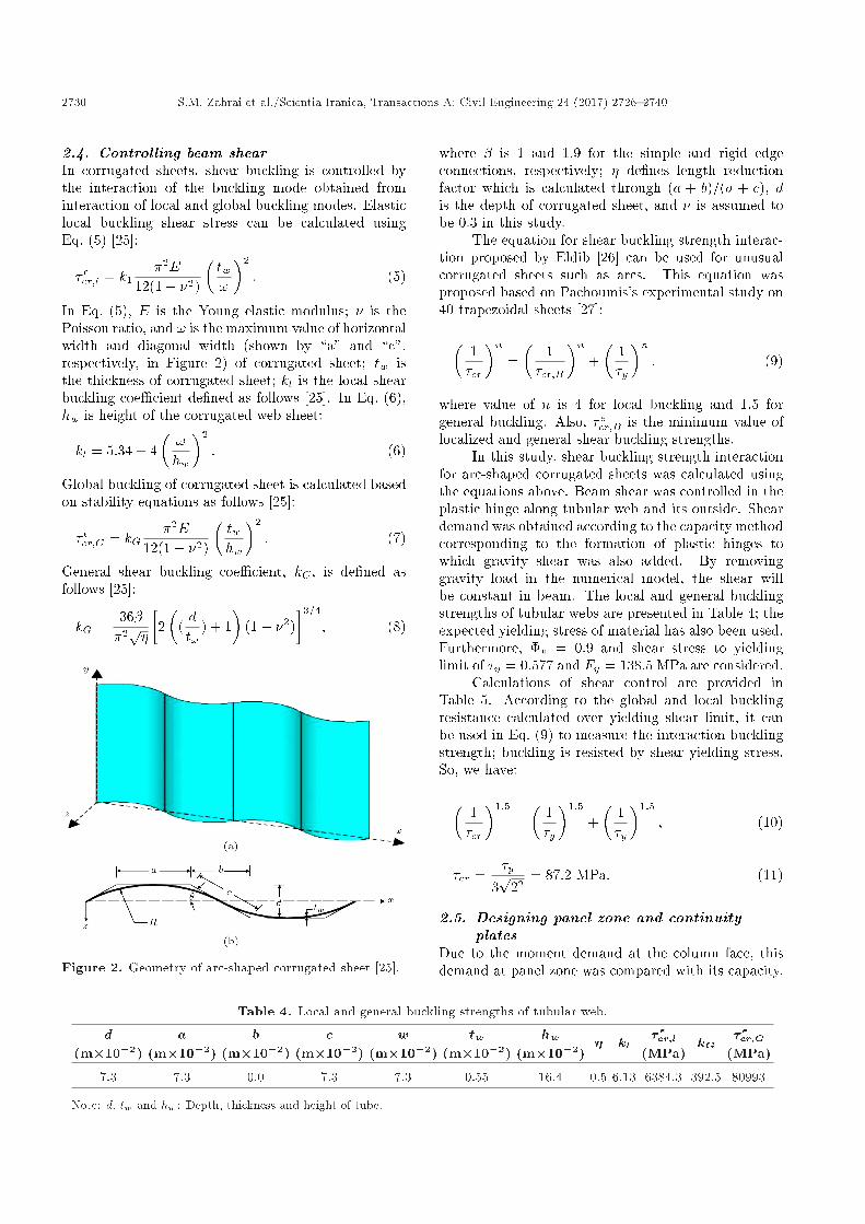
In Eq. (5), E is the Young elastic modulus; � is thePoisson ratio, and ! is the maximum value of horizontalwidth and diagonal width (shown by \a" and \c",respectively, in Figure 2) of corrugated sheet; tw isthe thickness of corrugated sheet; kl is the local shearbuckling coe�cient de�ned as follows [25]. In Eq. (6),hw is height of the corrugated web sheet:
kl = 5:34 + 4�!hw
�2
: (6)
Global buckling of corrugated sheet is calculated basedon stability equations as follows [25]:
�ecr;G = kG�2E
12(1� �2)
�twhw
�2
: (7)
General shear buckling coe�cient, kG, is de�ned asfollows [25]:
kG =36��2p�
�2�
(dt!
) + 1�
(1� �2)�3=4
; (8)
Figure 2. Geometry of arc-shaped corrugated sheet [25].
where � is 1 and 1.9 for the simple and rigid edgeconnections, respectively; � de�nes length reductionfactor which is calculated through (a + b)=(a + c), dis the depth of corrugated sheet, and � is assumed tobe 0.3 in this study.
The equation for shear buckling strength interac-tion proposed by Eldib [26] can be used for unusualcorrugated sheets such as arcs. This equation wasproposed based on Pachoumis's experimental study on40 trapezoidal sheets [27]:�
1�cr
�n=�
1�cr;B
�n+�
1�y
�n; (9)
where value of n is 4 for local buckling and 1.5 forgeneral buckling. Also, �ecr;B is the minimum value oflocalized and general shear buckling strengths.
In this study, shear buckling strength interactionfor arc-shaped corrugated sheets was calculated usingthe equations above. Beam shear was controlled in theplastic hinge along tubular web and its outside. Sheardemand was obtained according to the capacity methodcorresponding to the formation of plastic hinges towhich gravity shear was also added. By removinggravity load in the numerical model, the shear willbe constant in beam. The local and general bucklingstrengths of tubular webs are presented in Table 4; theexpected yielding stress of material has also been used.Furthermore, �v = 0:9 and shear stress to yieldinglimit of �y = 0:577 and Fy = 138:5 MPa are considered.
Calculations of shear control are provided inTable 5. According to the global and local bucklingresistance calculated over yielding shear limit, it canbe used in Eq. (9) to measure the interaction bucklingstrength; buckling is resisted by shear yielding stress.So, we have:�
1�cr
�1:5
=�
1�y
�1:5
+�
1�y
�1:5
; (10)
�cr =�y
3p
22= 87:2 MPa: (11)
2.5. Designing panel zone and continuityplates
Due to the moment demand at the column face, thisdemand at panel zone was compared with its capacity.
Table 4. Local and general buckling strengths of tubular web.
d(m�10�2)
a(m�10�2)
b(m�10�2)
c(m�10�2)
w(m�10�2)
tw(m�10�2)
hw(m�10�2)
� kl� ecr;l
(MPa)kG
�ecr;G(MPa)
7.3 7.3 0.0 7.3 7.3 0.55 16.4 0.5 6.13 6384.3 392.5 80993
Note: d, tw and hw: Depth, thickness and height of tube.

S.M. Zahrai et al./Scientia Iranica, Transactions A: Civil Engineering 24 (2017) 2726{2740 2731
Table 5. Shear control of at and tubular webs.
�cr(MPa)
tw(m�10�2)
hw(m�10�2)
Vnt(kN)
twf(m�10�2)
db(m�10�2)
Vnf(kN)
MTW�RBS
(kN�m)L
(m�10�2)V g
(m�10�2)Vu
(kN)Vu=
�yVntVu=
�yVnf87.2 0.55 16.4 157.3 0.53 16.4 125 52.05 145.5 0.0 35.77 0.25 0.32
Note: Vnt = 2�crtwhw: shear capacity of tube; twf and db: at web thickens and depth of beam;Vnf = 0:6Fy twfdb: shear capacity of at web;Vu = MTW-RBS=L: shear in plastic hinge; V g: gravity shear.
In these calculations, the shear strength reductionfactor of �� = 1:0 was considered. Minimum thicknessof shear panel was obtained from Eq. (12):
tz � wz + dz90
: (12)
In Eq. (12), wz and dz are the width and depth of panelzone, respectively; so, by substituting 18 and 18 cm inEq. (12), the minimum thickness of the panel zone is0.4 cm. This control criterion is established accordingto the thickness of box-column.
Continuity plates of 180�140�15 mm3 were usedin the panel zone. This sheet not only tolerates theimposed tensile and compressive force from the beam ange, but also conversely converts the axial force toshear force in panel zone, since the established length-to-width ratio is greater than 1.5 on this sheet. Inaddition, width-to-thickness ratio in b=t < 800=
pFy
is also satis�ed. Thus, the proposed model is alreadyde�ned and can be simulated with ABAQUS software.
3. Finite element modeling
Connections analysis is carried out using a three-dimensional �nite-element model in ABAQUS6.10.Given the assumption of the SHELL behavior of com-ponents in this model, deformable SHELL is de�nedfor all components. Four-node tetrahedral elementwith six degrees of freedom (three translational degreesand three rotational degrees) was used for meshingthe components. Mesh sizes of all components aresimilar (maximum dimension 1.5 cm) except for beam ange (maximum dimension 1.25 cm). All the regardedelements are square-shaped. This model focuses oninvestigating the model behavior; while connectionsweld is not explicitly modeled, however, degrees offreedom in connection zone are bound together withTie constraints (Figure 3).
3.1. Material propertiesDue to the fact that materials are supposed to exceedtheir linear range, the analysis should be done consider-ing nonlinear behavior. St37 steel with kinematic hard-ening and bilinear response curve was used to de�ne themechanical properties, where the slope of the elasticbehavior is (Young modulus) E = 2:03e+6 kg/cm2 andthe slope nonlinear behavior is obtained by connecting
yield point ("y; Fy) to failure point ("u; Fu) on stress-strain curve. Poisson ratio for steel is 0.3 in allanalyses.
3.2. De�nition of load type and analysisThe standard solver of ABAQUS software (ABA-QUS/Standard) was used for analyzing the model.In the load section, supports were de�ned by settingup boundary conditions. Furthermore, cyclic loadingwas imposed on the structure by de�ning boundaryconditions as a displacement on top of the columnbased on the 2010 AISC Seismic Provisions [23]. Themodel investigated by ABAQUS was loaded to reach9% story drift. The loading history consisted of sixcycles at 0.375%, 0.5%, and 0.75% total story driftangles, respectively. The next four cycles involved 1%story drift, followed by two cycles where each wouldsuccessively increase drift percentages (i.e., 2; 3; 4:::%).
Boundary condition for the bottom of the columnwas de�ned by �xing the degree of freedom in 3directions. Roller support was de�ned at a distanceof 154.5 cm from the column face by �xing degree offreedom in vertical direction. To de�ne lateral support,out-of-plane displacement of beam web was �xed at 45and 135 cm from the side of the column. Also, thecolumn was �xed with a lateral support in its upperhalf.
4. Numerical results
4.1. Expression of resultsLateral force-story drift cyclic curve is presented inFigure 4(a) for the proposed connection. The drift isobtained by dividing lateral displacement at the topof column to the column height. Also, Figure 4(b)provides the story drift-moment curve of beam atthe column face. The moment at the column faceis calculated through equilibrium in sub-structure.Increasing demand on these curves is due to subjectingmaterial in strain hardening area. Plastic story driftversus normalized moment curve at the column faceis also presented in Figure 4(c). Plastic story drift isobtained by subtracting the elastic story drift from thetotal story drift. The moment at the column face isnormalized to beam nominal exural capacity until theadditional resistance of structures is estimated.
The results of the proposed model satisfy the 2010

2732 S.M. Zahrai et al./Scientia Iranica, Transactions A: Civil Engineering 24 (2017) 2726{2740
Figure 3. Finite-element modeling for the proposed TW-RBS connection.
AISC seismic provisions' [23] acceptance criteria to con-�rm that special moment frame connection tolerates atleast 0.03 radian story drift, and the exural capacityof the specimen at the column face should not be lessthan 80% of the beam plastic moment at 0.04 radian
story drift. The proposed connection provides a stablecyclic behavior without strength reduction up to 9%story drift.
The von-Mises stress and strain contours at 0.06radian story drift are illustrated in Figure 5 for both

S.M. Zahrai et al./Scientia Iranica, Transactions A: Civil Engineering 24 (2017) 2726{2740 2733
Figure 4. Numerical results of the proposed model.
Figure 5. Von-Mises stress and strain contours at 0.06 radian story drift.
positive and negative bending moments. The stress isshown by units of kg/cm2. Gray color represents theyielding area, and tension contour shows formation ofplastic hinge at the center of corrugated area. Flangetension near column face is lower than that in theplace of plastic hinge formation. Studying the tensiondistribution in the corrugated web indicates that thevalue of tension in corrugated web is much lower thanthat in beam ange.
The results show that the hinge is formed atthe accordion area while the plastic strain in thesurrounding corrugated area has far less intensity, andthe rest of area remains elastic. This reduction in straindemand at the column face and full penetration weldsin beam-to-column connection signi�cantly reduce therisk of failure at the full penetration welds.
4.2. Results veri�cationOnly numerical studies may not be su�cient to supportthe TW-RBS connection. Cyclic plastic deformation,low cycle fatigue endurance, and the behavior of thewelds without cyclic tests are unknown on TW-RBSconnection. Then, for validation/calibration purposesof the numerical model, experimental test has beencarried out to study the behavior of TW-RBS moment
connections. All dimensions and design of connectionare according to what already mentioned for thenumerical model. Lateral force-story drift cyclic curveis presented in Figure 6 for TW-RBS test specimencompared with the numerical study. As shown in Fig-ure 6, TW-RBS test specimen provides a stable cyclicbehavior without strength reduction up to 8% story
Figure 6. Column tip force versus story drift forTW-RBS test specimen and numerical study.

2734 S.M. Zahrai et al./Scientia Iranica, Transactions A: Civil Engineering 24 (2017) 2726{2740
Figure 7. TW-RBS test specimen results.
drift satisfying the 2010 AISC seismic provisions [23]and FEMA [1] acceptance criteria up to 9% story driftwhile also validating the numerical model.
According to the test observations, �rst, yieldingemerged on the beam anges at the center of thereduced region during the �rst cycle of 1.5% storydrift cycles, as shown in Figure 7(a). It spread overthe entire reduced region and extended toward thecolumn face and beam end during next story drifts(Figure 7(b)). Flange local buckling was detected inthe reduced region on the both sides of beam following
the 4% story drift, as shown in Figure 7(c), and theamplitude of ange local buckling increased at thenext story drifts (Figure 7(d)). The yielding at thetubular web extended into the beam depth in the 6%story drift. In the �rst cycle of 7% story drift, lateral-torsional buckling of beam appeared in the top angeof left beam immediately after the reduced region, asshown in Figure 7(e). In the �rst cycle of 8% storydrift, the crack was initiated in the top ange of leftbeam immediately after the reduced region, as shownin Figure 7(f). The crack progressed to the middle of

S.M. Zahrai et al./Scientia Iranica, Transactions A: Civil Engineering 24 (2017) 2726{2740 2735
ange and fracture was initiated in the connection weldof tubular web to at web in this part during the secondcycle of 8% story drift. The cracks progressed downinto connection of the tubular web to at web duringthe �rst cycle of 9% story drift as shown in Figure 7(g).In the following second half of the �rst cycle of 9%, thecracks and rupture were initiated in the bottom angeof right beam, exactly in the reduced region as shownin Figure 7(h). According to the test, low cycle fatiguecannot happen at tubular webs and lateral-torsionalbuckling stability maintains up to high story drift.
5. Result comparison of TW-RBS versusAW-RBS
The connection proposed by Mirghaderi et al. [20] wasused in this section in order to compare the results.As explained in the literature, their connection was akind of reduced section using accordion web created bydouble angles 50� 50� 4 placed in IPE180 (Figure 8)with the same subassembly with the proposed TW-RBS connection. Therefore, it was considered as asuitable choice for comparison purposes.
5.1. Evaluation of numerical analysisobservations at di�erent story drifts
In order to have a better assessment of the proposedmodel results, numerical and experimental results atdi�erent story drifts on TW-RBS model were com-pared with the obtained experimental results of AW-RBS [20], as detailed in Table 6.
According to the results, in TW-RBS, local buck-ling of compression ange in the reduced section hasbeen created at 4% story drift, while in the AW-RBSconnection, buckling is noticed outside of the reducedsection between reduced section area and the columnface. The TW-RBS connection satis�es AISC seismicprovisions [23] and FEMA [1] acceptance criteria up to9% story drift, while the AW-RBS connection satis�esacceptance criteria up to 8%. Also, TW-RBS provides
a better condition in terms of low-cycle fatigue thanAW-RBS because the crack and rupture at TW-RBSwere �nally initiated in the ange, but crack wasinitiated in the angles at beam web in AW-RBS.
5.2. Evaluation of strain in numerical analysisIn order to investigate the plastic hinge region, themaximum plane strain was found on three points on thebeam ange axis, including the center of the reducedsection, i.e. a point near the reduced section at adistance of 4.5 cm from the column face, another pointin the beam-to-column connections, and the last pointon tubular web in the middle of pipe at its contact with ange, as shown in Figure 9. They are divided by yieldstrain to become the normalized strain.
The beam ange in the reduced section has highstrain, as shown in Figure 9, indicating that the plasticstrains are concentrated in this location. The ange ofbeam around the reduced region also has high strainlevel, whereas corrugated web experiences lower strain.The results show that the plastic hinge has occurred atthe section having the corrugated web and its centermatches the center of corrugated web area. Moreover, ange at beam to column connection has the lowestlevel of strain compared to other parts, con�rmingdemand reduction assumption at this location.
For AW-RBS, normalized strain of the ange atthe center of the reduced area at 0.03 radian storydrift was obtained 16, while a value of 25 was obtainedfor the analytical results of TW-RBS model, as shownin Figure 9, representing a higher strain level for theproposed model at the same story drift.
The strain envelope of top ange in a longitudinalsection of beam is illustrated in Figure 10. Evaluatingthe values presented in the curve shows that strainof ange in the reduced section zone of the proposedmodel is larger than those at other locations.
For AW-RBS, normalized strains at 0.02, 0.03,and 0.04 radian story drifts in the reduced section zonewere obtained 9, 13, and 15, respectively, whereas these
Figure 8. AW-RBS test specimen's details by Mirghaderi et al. [20].

2736 S.M. Zahrai et al./Scientia Iranica, Transactions A: Civil Engineering 24 (2017) 2726{2740
Table 6. Comparison of numerical results of the proposed model and experimental results of AW-RBS model.
Experimental and numericalstudy of TW-RBS model
Experimental and numericalstudy of AW-RBS model
Story drift
The �rst yeilding emerged at the center of thecorrugated region during the �rst cycle.
The �rst yeilding emerged at the center of thecorrugated region during the �rst cycle.
1.5%
Yeilding was completed at the corrugated regionand spread over the entire reduced region.
Yeilding was more apparent. 2%
The ange yeilding was extended and thisyeilding was apparent at tubular web in themiddle of connection part in the ange.
Yeilding of the reduced region was followed by aminor yeilding outside the reduced region nearthe column face, and also before the reduced region.
3%
Yeilding regions were extended and the ange localbuckling commenced inside the corrugated region.
Yeilding of beam ange extended and thenslightly towards the at web.
4%
Yeilding was apparent at the tubular web inconnection corner part to ange.
Yeilding became extensive adjacent to theconection beam to column peneteration welds.
5%
local buckling became extensive and theyielding at the tubular web extended into thebeam depth
A minor aking was detected at the corrugated webcorner, near the beam ange and the ange localbuckling commenced outside the corrugated region;this was then followed by web local buckling.
6%
Lateral-torsional buckling of beam appeared inthe top ange of left beam, immediately afterthe reduced region.
|| 7%
The ange yeilding was extended at depth andwidth of tubular web and the amplitudes of the ange buckling became more noticeable. Testresults show that the crack and rupture wereinitiated at the top ange of left beam,immediately after the reduced region.
The amplitudes of the ange and web buklingbecome more expensive and the right beamtop ange moved laterally, while it was incomperession.
8%
Test results show the cracks in the top ange ofleft beam progressed down into connection ofthe tubular web to at web and crack and rupturewere initiated in the bottom ange of right beam,exactly in the reduced region.
The ange and web buckling grew rapidly andthe ange lateral movment became expensive,cracks were found in the �llet welds at cornersof the corrugated plates near the left beambottom ange.
9%
values are respectively 12, 23, and 36 for TW-RBSmodel in the reduced section zone at the same storydrift. In comparison with AW-RBS, it represents anincrease of plastic strain in the reduced section zone ofthe proposed model.
Normalized strain curve on di�erent parts of tubu-lar web in TW-RBS model is presented in Figure 11in order to study the e�ects of accordion web. Asclearly shown, strain pro�le in corrugated web has asigni�cant decrease in all points in comparison withlinear pro�le of strain distribution in beam web, and
the accordion web behavior has caused great reductionof the axial strain of beam web at plastic hinge location.According to the curves, axial strain in the tubular webwas increased close to the beam ange, while by takingdistance from beam ange, the longitudinal strain ofthe web was highly decreased and became negligible.The absence of web in the exural strain leads to theelimination of web participation in exural capacity.
Evaluation of strain gained from the numericalanalysis of the proposed models shows more concen-tration of plastic strain in the reduced section of the

S.M. Zahrai et al./Scientia Iranica, Transactions A: Civil Engineering 24 (2017) 2726{2740 2737
Figure 9. Normalized strain push versus story drift.
Figure 10. Envelope of normalized strain on the beam ange at di�erent distances from the column face.
Figure 11. Envelope of normalized strain at di�erentdistances from the neutral axis.
proposed model compared to the previous experimentaland numerical studies of AW-RBS, demonstrating moreductility for the proposed model.
6. Conclusions
In this study, a new type of RBS connection, TW-RBS, was evaluated through cutting continuous weband replacement of that part with a tube. Overall,the numerical and experimental results demonstratedthat TW-RBS provides signi�cant ductility up to 8%story drift without reducing the bending strength atthe column face. It is noteworthy that TW-RBSsatis�es the 2010 AISC seismic provisions [23] andFEMA 350 [1] acceptance criteria up to 9% storydrift. Moreover, a connection with TW-RBS was alsoprovided with more strain and tension concentrationin the reduced section of the ange compared to theconnection proposed by Mirghaderi et al. [20]. Inaddition, the following are concluded:
� The results indicate that due to exural strengthreduction by replacing web in the proposed con-nection, using TW-RBS reduces the plastic straindemand near complete joint penetration welds ande�ectively concentrates the plastic strains within thereduced region;

2738 S.M. Zahrai et al./Scientia Iranica, Transactions A: Civil Engineering 24 (2017) 2726{2740
� The plastic hinge capacity can only be estimated inthe reduced region based on the beam anges, andthe contribution of the beam web to the plastic hingecapacity is negligible because of the web accordionbehavior;
� The most important feature of using the tubular webis to improve the out-of-plane sti�ness about thebeam longitudinal axis and also the ange stabilitycondition due to the smaller width-to-thickness ratioof beam ange. Also, according to the numericaland experimental results, ange local buckling wasdetected inside the reduced region in TW-RBSconnection;
� Tubular web provides a better condition in terms oflow-cycle fatigue than accordion web because changeof strain direction in arc shape of the tabular websection creates smaller angles compared to sharpcorners of the accordion section.
Despite the acceptable seismic performance of thedesigned connection, the results may not necessarily beextrapolated to the deeper beams used frequently inmoment frame constructions. Therefore, complemen-tary experimental program in the next stage of thisresearch is underway by authors for deep beams andfurther validation purposes.
Acknowledgment
Authors would like to thank the University of Tehranand the Islamic Azad University, Professor HesabiBranch, for supporting this research.
References
1. Federal Emergency Management Agency, FEMA-350,Seismic Design Criteria for New Moment ResistingSteel Frame Construction, Washington DC (2000).
2. Federal Emergency Management Agency, FEMA-355D \State of the art report on connection perfor-mance", Washington DC (2000).
3. Chen, S.J. and Chao, Y.C. \E�ect of composite actionon seismic performance of steel moment connectionswith reduced beam sections", Journal of ConstructionSteel Research, 57, pp. 417-434 (2001).
4. Uang, C.-M. and Fan, C.-C. \Cyclic stability criteriafor steel moment connections with reduced beam sec-tion", Journal of Structural Engineering, 127(9), pp.1021-1027 (2001).
5. Nakashima, M. and Kanao, I. \Lateral instabilityand lateral bracing of steel beams subjected to cyclicloading", Journal of Structural Engineering, 128(10),pp. 1308-1316 (2002).
6. Jay-Shen, J.H., Astaneh-Asl, A. and McCallen, D.Use of Deep Columns in Special Steel Moment Frames,AISC, Steel Tips (2002).
7. Jones, S.L., Fry, G.T. and Engelhardt, M.D. \Experi-mental evaluation of cyclically loaded reduced beamsection moment connections", Journal of StructuralEngineering, 128(4), pp. 441-451 (2002).
8. Roeder, C.W. \Connection performance for seismicdesign of steel moment frames", Journal of StructuralEngineering, 128(4), pp. 517-525 (2002).
9. Ricles, J.M., Fisher, J.W., Lu, L.-W. and Kaufmann,E.J. \Development of improved welded moment con-nections for earthquake-resistant design", Journal ofConstructional Steel Research, 58, pp. 565-604 (2002).
10. Lee, C.H., Jeon, S.W., Kim, J.H. and Uang, C.M.\E�ect of panel zone strength and beam web con-nection method on seismic performance of reducedbeam section steel moment connection", Journal ofStructural Engineering, 131(12), pp. 1854-1865 (2005).
11. Moslehi Tabar, A. and Deylami, A. \Instability ofbeams with reduced beam section moment connectionsemphasizing the e�ect of column panel zone ductility",Journal of Constructional Steel Research, 61(11), pp.1475-1491 (2005).
12. Zhang, X. and Ricles, J.M. \Experimental evaluationof reduced beam section connections to deep columns",Journal of Structural Engineering, 132(3), pp. 346-357(2006).
13. Zhang, X. and Ricles, J.M. \Seismic behavior ofreduced beam section moment connections to deepcolumns", Journal of Structural Engineering, 132(3),pp. 358-367 (2006).
14. Han, S.W. and Moon, H.H. \Design equations formoment strength of RBS-B connection", Journal ofConstruction Steel Research, 65, pp. 1087-1095 (2009).
15. Pachoumis, D.T., Galoussis, E.G., Kalfas, C.N. andEfthimiou, I.Z. \Cyclic performance of steel moment-resisting connections with reduced beam sections-experimental analysis and �nite element model sim-ulation", Engineering Structures, 32(9), pp. 2683-2692(2010).
16. Wilkinson, S., Hurdman, G. and Crouther, A. \Amoment resisting connection for earthquake resistingstructure", Journal of Constructional Steel Research,62, pp. 295-302 (2006).
17. Prasada-Rao, D.V. and Satish-Kumar, S.R. \RHSbeam-to-column connection with web opening-parametric study and design guidelines", Journal ofConstructional Steel Research, 62, pp. 747-756 (2006).
18. Yang, Q. and Yang, N. \Seismic behaviors of steelmoment resisting frames with opening in beam web",Journal of Constructional Steel Research, 65(6), pp.1323-1336 (2009).
19. Elgaaly, M., Hamlton, R. and Seshadri, A. \Shearstrength of beams with corrugated webs", Journal ofStructural Engineering, 122(4), pp. 390-398 (1997).

S.M. Zahrai et al./Scientia Iranica, Transactions A: Civil Engineering 24 (2017) 2726{2740 2739
20. Mirghaderi, S.R., Torabian, S. and Imanpour, A.\Seismic performance of the Accordion-Web RBS con-nection", Journal of Constructional Steel Research, 66,pp. 277-288 (2010).
21. Saleh, A., Zahrai, S.M. and Mirghaderi, S.R. \Exper-imental study on innovative tubular web RBS con-nections in steel MRFs with typical shallow beams",Structural Engineering & Mechanics, 57(5), pp. 71-88(2016).
22. Morrison, M., Schweizer, D. and Hassan, T. \An in-novative seismic performance enhancement techniquefor steel building moment resisting connections", Jour-nal of Constructional Steel Research, 109, pp. 34-46(2015).
23. American Institute of Steel Construction, AISC, Seis-mic Provisions for Structural Steel Buildings, Chicago(2010).
24. Engelhardt, M., Winneberger, T., Zekany, A. andPotyraj, T. \Experimental investigation of Dogbonemoment connections", Eng. J. AISC, Fourth Quarter,pp. 128-139 (1998).
25. Eldib, M.E. \Shear buckling strength and design ofcurved corrugated steel webs for ridges", Journalof Constructional Steel Research, 65, pp. 2129-2139(2009).
26. Eldib, M.E. \Buckling analysis of beams with corru-gated webs", Proceeding of 5th International Confer-ence on Civil and Architecture Eng. (ICCAE Conf),(2004).
27. Hamilton, R.W. \Behavior of welded girder with corru-gated webs", Ph.D. Dissertation, University of Maine,Maine (1993).
Appendix
Assessment of resistance mechanisms of thetubular Web RBS connection (TW-RBS)To evaluate the axial resistance of tubular web in thereduced region and compare it with the axial resistanceof a at web, a cylindrical bar with the depth of the unitis considered. According to Figure A.1, the ultimatecondition of a cylindrical bar under the e�ect of Pmakes four hinges at the end points and the centerpoint of the circular. Free body diagram of quartersegments can be considered due to the establishmentof symmetry. Accordingly, by writing the momentbalance equation at a plastic joint, Pcorr force can beobtained as follows:
Pcorr =8Mpc
D=
8 tc2
4 FyD
=2tc2FyD
: (A.1)
By taking the same height and letting Af = tf for atsheet, we have:
P at = AfFy = tfFy: (A.2)
Figure A.1. Free energy diagram for a cylindrical barand a at bar to a depth of the unit.
Measurement of the impact on the resistanceproperties of tubular accordion web and a comparisonbetween the tube resistance and at web, StrengthDegradation Factor (SDF) can be calculated as follows:
SDF = 1� Pcorr
P at= 1� 2
�tctf
�2�Dtf
� : (A.3)
Based on the equation above, SDF is a function of pipediameter ratio to at web and tube thickness ratio to at web.
Beam plastic moment in the corrugated area canbe written as a function of axial resistance P at or Pcorr.Letting p(y) = �p for negative values of y and p(y) = pfor positive values of y in the web plastic state, and alsothe cross-section is symmetric about the neutral axis;plastic moment is calculated as follows:
M =Ph2
4: (A.4)
In this case, p is the axial strength and can be replacedby Pcorr or P at. Because the plastic moment of websection is equal to ZwebFy, then modulus of the plasticportion of web can be calculated as follows:
M =Ph2
4= ZwebFy; (A.5)
Zweb =Ph2
4Fy: (A.6)
Since the plastic modulus calculated by the contri-bution of web directly depends on the inside axialstrength, the ratio of the plastic modulus of the tubularweb to plastic modulus of the at web is Pcorr=P atproportionally.
In other words, the reduction factor of web plasticmodulus is equal to SDF. According to the results, theplastic modulus of the I-shaped beam along the tubulararea can be calculated as follows:
ZAWS = Z ange + (1� SDF)Z atweb: (A.7)
Biographies
Seyed Mehdi Zahrai was born in Tehran, Iran, in1964. He received his BSc degree in Civil Engineering

2740 S.M. Zahrai et al./Scientia Iranica, Transactions A: Civil Engineering 24 (2017) 2726{2740
from Tehran Polytechnic in 1987, his MSc degree inStructural Engineering from the University of Tehranin 1990, and his PhD in Structural Engineering fromthe University of Ottawa in 1997. He has been aProfessor at the School of Civil Engineering, Univer-sity of Tehran, since 1999. He has authored manypublications, including 10 books and more than 380journals and conference papers, supervised about 140theses and research projects, managed and directedmany large steel and concrete building tower or bridgeprojects in design and construction phases, served a fewconferences as the chairman, and has been a memberof editorial board or reviewer in many internationaljournals. Dr. Zahrai has been also a member of manyscienti�c societies and innovation advisory committeesin Iran, awarded a few times for teaching or researchand uniquely recognized for about 300 workshops andeducational sessions held on di�erent aspects of seismicdesign, retro�t and construction of steel and concretebuilding and bridge structures.
Seyed Rasoul Mirghaderi was born in Esfehan,Iran in 1954. He received his BSc degree in CivilEngineering from the Sharif University, Iran, in
1976, and his MSc and PhD degrees in StructuralEngineering from the Purdue University, USA,in 1980 AND 1981, respectively. He has been aProfessor at the School of Civil Engineering, theUniversity of Tehran, since 1987. He has authoredmany publications including 11 books, more than250 journals, and conference papers, so far supervisedabout 100 theses and research projects, managed anddirected many large steel and concrete building towerprojects in design and construction phases, and serveda few conferences as the chairman. Dr. Mirghaderihas been also a member of many scienti�c societiesand innovation advisory committees in Iran.
Aboozar Saleh was born in Tehran, Iran in 1979. Hereceived his BSc in Civil Engineering from the TehranPolytechnic in 2002, his MSc degree in StructuralEngineering from the Sharif University, Iran, in 2004,and his PhD degree in Earthquake Engineering fromthe University of Tehran, in 2016. He has been an As-sistance Professor at the Islamic Azad University Pro-fessor Hesabi Branch since 2005. He has authored morethan 20 journal and conference papers. His researchinterests are seismic analyses and structural control.