tubing and pipes - inicio · allowable working pressures are based on equations from asme b31.3 for...
TRANSCRIPT

Tubing, Pipes, Hoses and ConnectorsDTubing and Pipes...............D-02
Hoses and Connectors ............D-18
Tubing and Pipes
Tubing and Pipes D-02

Tubing and Pipes D-04D-03 Tubing and Pipes
Proper selection, handling, and installation of tubing, when combined with proper selection of FITOK tube fittings, are
essential for reliable tubing systems.
The following variables should be considered when ordering tubing for use with tube fittings:
Surface finish
Material
Hardness
Wall thickness
FITOK
◎
◎
◎
◎
Tubing Selection
It is important to properly handle the tubing in order to reduce the scratches and protect the surface finish.
Tubing should never be dragged out of a tubing rack or across a rough surface.
Tube cutters or hacksaws should be sharp. Do not take deep cuts with each turn of the cutter or stroke of the saw.
The tubing will go all the way through the ferrules without damaging the ferrule sealing edge.
◎
◎
Tubing Handling
Wall Thickness
The accompanying tables show working pressure ratings of tubing in a wide range of wall thicknesses. Except as noted,
allowable pressure ratings are calculated from S values as specified by ASME B31.3, Process Piping. FITOK tube fittings have
been repeatedly tested in both the minimum and maximum wall thicknesses shown. FITOK tube fittings are not recommended
for tube wall thicknesses outside the ranges shown in the accompanying tables for each size.
tube fittings are designed to work properly with the tubing that is suggested in the ordering instructions.
stainless steel tube fittings have been repeatedly tested successfully with tubing with hardness up to 200 HV and 90 HRB.
FITOK FITOK
Hardness
Material
Metal tubing material should be softer than fitting material. For example, stainless steel tubing should not be used with
brass fittings. When tubing and fittings are made of the same material, tubing must be fully annealed.
Surface finish is very important to proper sealing. Tubing with any kind of depression, scratch, raised portion, or other surface
defect will be difficult to seal, particularly in gas service.
Surface Finish
Contents
Tubing
Pipes
Stainless Steel Seamless Pipe D-17
D-05
D-08
D-09
Stainless Steel Seamless Tubing
Copper Tubing
Carbon Steel Tubing
Suggested Allowable Working Pressure Tables
D-11
D-11
D-12
D-12
D-13
D-13
D-14
D-10
Alloy C-276 Tubing
Alloy 20 Tubing
Alloy 600 Tubing
Grade 2 Titanium Tubing
SAF 2507 Super Duplex Tubing
Alloy 825 Tubing
Alloy 625 Tubing
Alloy 400 Tubing
Suggested Allowable Working Pressure for Additional Alloys
D-14Pressure Ratings at Elevated Temperatures
D-16
D-15
Part Number Description
Ordering Information
Base Ordering Number
D-04Tubing Selection
D-04Tubing Handling
D-05Gas Service
D-05Tubing Installation

Tubing and Pipes D-06D-05 Tubing and Pipes
Metric, mm
19
21
23
25
31
32
34
40
46
50
54
63
3
6
8
10
12
14
15
16
18
20
22
25
28
30
32
38
50 80
1/2
23/32
3/4
13/16
7/8
15/16
1 3/16
1 1/4
1 5/16
1 1/2
2
2 13/32
3 1/4
Required straight tube length.
1/16
1/8
3/16
1/4
5/16
3/8
5/8
3/4
7/8
1 1/4
1 1/2
2
1
➀
Fractional, in.
TTube O.D. L➀ L➀
TTube O.D.
1/2
Tubing Installation
R
T
L
T Tube O.D.
L Required straight tube
length (see tables)
R Radius of tubing bend
Tubing properly selected and handled, combined with
properly installed tube fittings, will give you a
leaktight system and provide reliable service in a wide
variety of applications.
For maximum assurance of reliable performance, use:
Properly selected and handled high-quality tubing
such as provided by
tube fittings assembled in accordance
instructions.
An appropriate tube support system to limit the
movement of tubing and fluid system components.
When installing fittings near tube bends, there must be
sufficient straight length of tubing to allow the tube
bottomed in the fitting see tables
FITOK
— FITOK.
FITOK with
catalog
a
to be FITOK ( ).
◎
◎
◎
Figures and tables are for reference only. No implication is made that these values can be used for design work. Applicable
codes and practices in industry should be considered.
All pressures are calculated from equations in ASME B31.3, Process Piping. See factors for calculating working pressures in
accordance with ASME B31.1, Power Piping.
No allowance is made for corrosion or erosion.
Calculations are based on maximum O.D. and mimimum wall thickness, except as noted in individual tables.
Example: 1/2 in. O.D.×0.049 in. wall thickness stainless steel tubing purchased to ASTM A269:
O.D. Tolerance ±0.005 in. / Wall Thickness Tolerance ±10%
Calculations are based on 0.505 in.O.D.×0.0441 in. wall thickness tubing.
◎
◎
◎
Gas Service
Gases air, hydrogen, helium, nitrogen, etc.) have very small molecules that can escape through even the most minute
leak path. Some surface defects on the tubing can provide such a leak path. As tube outside diameter (O.D.) increases,
so does the likelihood of a scratch or other surface defect interfering with proper sealing.
The most successful connection for gas service will occur if all installation instructions are carefully followed and the
heavier wall thicknesses of tubing on the accompanying tables are selected.
(
Suggested Allowable Working Pressure Tables
1/16
1/8
3/16
1/4
5/16
3/8
1/2
5/8
3/4
7/8
1
1 1/4
1 1/2
0.010 0.012 0.014 0.016 0.020 0.028 0.035 0.049 0.065 0.083 0.095 0.109 0.120 0.134 0.156 0.188
Nominal Wall Thickness, in.
Working Pressure, psig
Note: For gas service, select a tube thickness outside of the shaded area.
Table 1 — Fractional Stainless Steel Seamless Tubing
Allowable working pressures are calculated from an
S value of 20 000 psi (137.8 MPa) for ASTM A269 tubing
at -20 to 100°F (-28 to 37°C), as listed in ASME B31.3,
except as noted. Multiply stainless steel rating by 0.94
for working pressure in accordance with ASME B31.1.
Suggested Allowable Working Pressure for Stainless Steel Tubing
For Welded Tubing
Suggested Ordering Information
For welded and drawn tubing, a derating factor must be
applied for weld integrity:
For double-welded tubing, multiply working pressure
by 0.85.
For single-welded tubing, multiply working pressure
by 0.80.
◎
◎
TubeO.D.(in.)
High-quality, fully annealed (Type 304, 304L, 316, 316L) (seamless or welded and drawn) stainless
steel hydraulic tubing, ASTM A269 or A213, or equivalent. Hardness not to exceed 90 HRB or 200 HV. Tubing to be free
of scratches, suitable for bending and flaring. O.D. tolerances not to exceed 0.003 in. for 1/16 in. O.D. tubing.
Note: Certain austenitic stainless tubing has an allowable ovality tolerance double the O.D. tolerance and may not fit into
precision tube fittings. Dual-certified grades such as 304/304L and 316/316L meet the minimum chemistry and
the mechanical properties of both alloy grades.
±
FITOK
5600 6800 8100 9400 12000
8500 10900
5400 7000 10200
4000 5100 7500
4000 5800
3300 4800
2600 3700 6700
2900 5200 6000
2400 4200 4900 5800
2000 3600 4200 4800
10200
8000
6500
5100
4000
3300
2800
2400 3100 3600 4200 4700
2400 2800 3300 3600 4100 4900
2300 2700 3000 3400 4000 4900
Table 2—Metric Stainless Steel Seamless Tubing
For Welded Tubing
Allowable working pressures are based on equations
from ASME B31.3 for EN ISO 1127 tubing (D4, T4
tolerance for 3 to 12 mm; D4, T3 tolerance 14 to 50 mm),
using a stress value of 137.8 MPa (20 000 psi) and tensile
strength of 516.4 MPa (74 900 psi), except as noted.
Multiply stainless steel rating by 0.94 for working pressure
in accordance with ASME B31.1.
For welded and drawn tubing, a derating factor must
be applied for weld integrity:
For double-welded tubing, multiply working pressure
by 0.85.
For single-welded tubing, multiply working pressure
by 0.80.
◎
◎

Tubing and Pipes D-08D-07 Tubing and Pipes
3
6
8
10
12
14
15
16
18
20
22
25
28
30
32
38
0.8 1.0 1.2 1.5 1.8 2.0 2.2 2.5 2.8 3.0 3.5 4.0 4.5
Nominal Wall Thickness, mmTubeO.D.(mm) Working Pressure, bar
670
310 420 540 710
310 390 520
240 300 400 510 580
200 250 330 410 470
160 200 270 340 380 430 490
150 190 250 310 360 400 450
170 230 290 330 370 400
150 200 260 290 320 370
140 180 230 260 290 330 380
140 160 200 230 260 300 340
180 200 230 260 290 320
180 200 230 260 280 330
170 180 210 240 260 310
160 170 200 220 240 290 330
140 160 190 200 240 270 310
4.5
Suggested Allowable Working Pressure for Carbon Steel Tubing
Table 3 — Fractional Carbon Steel Tubing
Allowable working pressures are calculated from an S value of 15 700 psi (108.2 MPa) for ASTM A179 tubing at -20 to 100
( 28 to 37 ), as listed in ASME B31.3. For working pressure in accordance with ASME B31.1, multiply by 0.85.
°
°
F
- C
High-quality, soft annealed seamless carbon steel hydraulic tubing, ASTM A179 or equivalent. Hardness not to exceed
72 HRB or 130 HV. Tubing to be free of scratches, suitable for bending and flaring.
8000
5100
3700 9600
7500
6200
4500 5900
3500 4600 5300
2900 3700 4300 5100
2400 3200 3700 4300
2100 2700 3200 3700 4100
1600 2100 2500 2900 3200 3600 4000 4600 5000
1800 2000 2400 2600 2900 3300 3700 4100 5100
0.028
Working Pressure, psig
Tube Wall Thickness, in.
0 035. 0 049. 0 065. 0 083. 0 095. 0 109. 0 120. 0 134. 0 148. 0 165. 0 180. 0 220.
TubeO.D.(in.)
1/8
3 16/
1 4/
5 16/
3 8/
1/2
5/8
3/4
7/8
1
1 1/4
1 1/2
9600
7000
5500
4500
3200
2600
2100
1800
1500
10200
6600
4800
3700
3100
2300
1800
Suggested Ordering Information
Table 4 — Metric Carbon Steel Tubing
Allowable working pressures are based on equations from ASME B31.3 for DIN 2391 tubing, using a stress value of
113 MPa (16 300 psi) and tensile strength of 340 MPa (49 300 psi).
High-quality, soft annealed carbon steel tubing, DIN 2391 or equivalent. Hardness not to exceed 72 HRB or 130 HV.
Tubing to be free of scratches, suitable for bending and flaring.
Suggested Ordering Information
630 790
290 370 460 590
270 330 430
210 260 330
170 210 270 330 380 420
150 180 230 280 320 350
140 170 210 260 290 330
130 150 200 240 270 300 350
140 170 210 240 270 310
120 160 190 210 240 270 310
110 140 170 190 210 240 280
100 120 150 170 180 210 240 260
150 160 190 210 230 270
140 150 170 200 210 250
130 140 160 180 200 230 270
120 130 150 160 190 230 260
3
6
8
10
12
14
15
16
18
20
22
25
28
30
32
38
Working Pressure, bar
Tube Wall Thickness, mmTubeO.D.(mm)
0 8. 1 0. 1 2. 1 5. 1 8. 2 0. 2 2. 2 5. 2 8. 3 0. 3 5. 4 0. 4 5.
Note: For gas service, select a tube thickness outside of the shaded area.
Note: For gas service, select a tube thickness outside of the shaded area.
Suggested Ordering Information
High-quality, fully annealed (Type 304, 304L, 316, 316L) stainless steel tubing, EN ISO 1127 or equivalent. Hardness not to exceed 90 HRB or
200 HV. Tubing to be free of scratches, suitable for bending and flaring. O.D. tolerances not to exceed ±0.076 mm for 3 mm O.D. tubing.
Note: Dual-certified grades such as 304/304L, 316/316L meet the minimum chemistry and the mechanical properties
of both alloy grades.
Note: For gas service, select a tube thickness outside of the shaded area.
Tolerances for W.T. Lenth Tolerances
for Lenth
mm mm inch mm mm mm mm
0.035 1.0
0.035 1.0
0.035 1.0
0.049 1.2
0.049 1.2
0.065 1.5
0.049 1.2
0.065 1.5
0.065 1.5
0.065 1.5±0.20
+0.05-0.00
±0.10
±0.05
±0.10
4000+3.00-0.00
Wall Thickness
Dimensions and Tolerances:
Tolerances for O.D.
6
10
38
50
12
20
25
inch
Tube O.D.
1/4
3/8
1-1/2
2
1/2
3/4
1
BA (Bright Annealing) Tubing
Features: Finish-rolling with bright annealing treatment, achieving good internal surface finish; Hardness under HRB80; Low carbon, high
nickel, high chromium and molybdenum, better corrosion resistance; Close dimensional tolerance, better consistency in application; Longer
service life in marine environment application; Applicable to clean industry, such as semiconductor, biological pharmaceuticals, food proce-
ssing and other fields.
Composition:
C Mn P S Si Ni Cr Mo
≤0.035 ≤2.00 ≤0.045 ≤0.015 ≤1.00 12.0-14.0 17.0-18.0 2.50-3.00
Chemical Component
Internal Surface States:
Ra (μm) Ra (μinch)
≤0.38 ≤151/4 (6) OD≤ ≤22 (50)
Dimension in. (mm) Internal Surface Finish
MP (Mechanical Polishing) Tubing
Features: Cold drawn and with mechanical polishing,
acid pickling of internal surface; Hardness under HRB80;
Composition: In accordance with the standard require-
ments, please refer to the corresponding standard.
Dimensions and Tolerance: In accordance with the sta-
ndard requirements, please refer to the corresponding
standard.
Internal surface state: acid pickling, surface finish
Ra .≤ μ3.2 m
316/316L
Material

Tubing and Pipes D-10D-09 Tubing and Pipes
Allowable working pressures are calculated from an S value of 6000 psi (41.3 MPa) for ASTM B75 (B75M) and ASTM B88 (B88M)
tubing at 20 to 100 ( 28 to 37 ), as listed in ASME B31.3 and ASME B31.1.- F - C° °
Suggested Allowable Working Pressure for Copper Tubing
Table 5 — Fractional Copper Tubing
Working Pressure, psig
1/2
1/8
3/16
1/4
5/16
3/8
5/8
3/4
7/8
1
1 1/8
Tube Wall Thickness, in.TubeO.D.(in.)
High-quality, soft annealed seamless copper tubing, ASTM B75 (B75M) or equivalent. Also soft annealed
(Temper O) copper water tube, type K or type L to ASTM B88 (type A or type B to ASTM B88M).
Suggested Ordering Information
Table 6 — Metric Copper Tubing
Working Pressure, bar
Tube Wall Thickness, mmTubeO.D.(mm)
0.8 1.0 1.2 1 5. 1 8. 2.0 2 2. 2 5. 2 8. 3.0
0.028 0 030. 0 035. 0 049. 0 065. 0 083. 0 095. 0 109. 0 120. 0 134.
2700 3000 3600
1800 1900 2300 3400
1300 1400 1600 2500 3500
1300 1900 2700
1000 1600 2200
800 1100 1600 2100
900 1200 1600 1900
700 1000 1300 1500 1800
600 800 1100 1300 1500
500 700 900 1100 1300 1500
600 800 1000 1100 1300 1400
6
8
10
12
14
15
16
18
20
22
25
28
110 140 170 220
100 120 160
80 100 130
60 80 100 130 140
50 60 90 110 120
60 80 100 110 120
70 90 100 110 120
60 80 90 100 110
60 70 80 90 100 110
50 60 70 80 90 100
40 50 60 70 80 90 100
40 50 60 70 80 90
130
Note: For gas service, select a tube thickness outside of the shaded area.
Suggested Allowable Working Pressure for Additional Alloys
Alloy 400 Tubing
Allowable working pressures are calculated from an S value of 18 700 psi (128.9 MPa) for ASTM B165 tubing at 20 to 100
(-28 to 37 C), as listed in ASME B31.3 and ASME B31.1.
- °F
°
A limited amount of test data is available on tube fittings used with special alloy tubing. For sizes not listed in the
following tables, we recommend that a sample of the tubing be provided for evaluation before installation. Please include
all pertinent information relating to system parameters. Give tubing sample to any of authorized FITOK representatives to
forward to the factory.
FITOK
Working Pressure, psig
0.028 0 035. 0 049. 0 065. 0 083. 0 095. 0 109. 0 120.
Tube Wall Thickness, in.TubeO.D.(in.)
Table 7 — Fractional
High-quality, fully annealed seamless alloy 400 hydraulic tubing, ASTM B165 or equivalent. Hardness not
to exceed 75 HRB or 137 HV. Tubing to be free of scratches, suitable for bending and flaring. O.D. toler-
ances not to exceed ±0.005 in (±0.13 mm).
Suggested Ordering Information
Table 8 — Metric
Working Pressure, bar
Tube Wall Thickness, mmTubeO.D.(mm)
0.8 1.0 1.2 1 5. 1 8. 2.0 2 2. 2 5. 2 8. 3.0
7900
3700
10 100
4 800
3 700
3 100
2 300
7000
5400
4400
3200
2200
9500
7300
6100
4400
3000
2200
4000
2900
4600
3400 3900 4300
1/8
1/4
5/16
3/8
1/2
3/4
1
6
8
10
12
14
18
20
25
310 620
450
350
290
390
290
220
180
160 240 270
490
350
280
230
190
150 200 240 270 300
180 210 240 270 290
170 190 210 240 270 290
Note: For gas service, select a tube thickness outside of the shaded area.
Note: For gas service, select a tube thickness outside of the shaded area.
Note: For gas service, select a tube thickness outside of the shaded area.
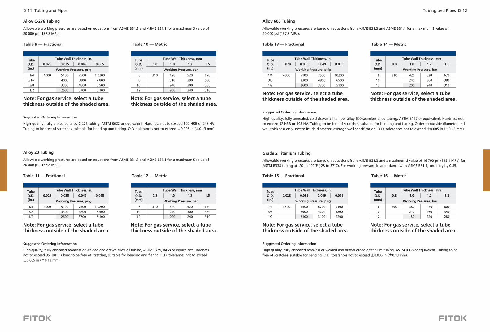
Tubing and Pipes D-12D-11 Tubing and Pipes
Allowable working pressures are based on equations from ASME B31.3 and ASME B31.1 for a maximum S value of
20 000 psi (137.8 MPa).
Alloy C-276 Tubing
Working Pressure, psig
TubeO.D.(in.)
0.028 0 035. 0 049. 0 065.
Tube Wall Thickness, in.
High-quality, fully annealed alloy C-276 tubing, ASTM B622 or equivalent. Hardness not to exceed 100 HRB or 248 HV.
Tubing to be free of scratches, suitable for bending and flaring. O.D. tolerances not to exceed ±0.005 in (±0.13 mm).
Suggested Ordering Information
Table 9 — Fractional Table 10 — Metric
4000 5100 7500
4000 5800
3300 4800
1/4
5/16
3/8
2600 3700
1 0200
7 800
6 500
5 100
310 420 520 670
310 390 500
240 300 380
6
8
10
12 200 240 310
Working Pressure, bar
TubeO.D.(mm)
Tube Wall Thickness, mm
0.8 1 0. 1 2. 1 5.
Allowable working pressures are based on equations from ASME B31.3 and ASME B31.1 for a maximum S value of
20 000 psi (137.8 MPa).
Alloy 20 Tubing
High-quality, fully annealed seamless or welded and drawn alloy 20 tubing, ASTM B729, B468 or equivalent. Hardness
not to exceed 95 HRB. Tubing to be free of scratches, suitable for bending and flaring. O.D. tolerances not to exceed
±0.005 in .(±0.13 mm)
Suggested Ordering Information
Working Pressure, psig
TubeO.D.(in.)
0.028 0 035. 0 049. 0 065.
Tube Wall Thickness, in.
Table 11 — Fractional Table 12 — Metric
Working Pressure, bar
TubeO.D.(mm)
Tube Wall Thickness, mm
0.8 1 0. 1 2. 1 5.
5100 7500
3300 4800
2600 3700
1 0200
6 500
5 100
310 420 520 670
240 300 380
6
10
12 200 240 310
1/4 4000
3/8
1/2
1/2
Note: For gas service, select a tube thickness outside of the shaded area.
Note: For gas service, select a tube thickness outside of the shaded area.
Note: For gas service, select a tube thickness outside of the shaded area.
Note: For gas service, select a tube thickness outside of the shaded area.
Allowable working pressures are based on equations from ASME B31.3 and ASME B31.1 for a maximum S value of
20 000 psi (137.8 MPa).
Alloy 600 Tubing
Table 13 — Fractional Table 14 — Metric
Allowable working pressures are based on equations from ASME B31.3 and a maximum S value of 16 700 psi (115.1 MPa) for
ASTM B338 tubing at -20 to 100 F (-28 to 37 C). For working pressure in accordance with ASME B31.1, multiply by 0.85.° °
Grade 2 Titanium Tubing
Table 15 — Fractional Table 16 — Metric
High-quality, fully annealed seamless or welded and drawn grade 2 titanium tubing, ASTM B338 or equivalent. Tubing to be
free of scratches, suitable for bending. O.D. tolerances not to exceed (±0.13 mm).±0.005 in
Suggested Ordering Information
Working Pressure, psig
TubeO.D.(in.)
0.028 0 035. 0 049. 0 065.
Tube Wall Thickness, in.
Working Pressure, bar
TubeO.D.(mm)
Tube Wall Thickness, mm
0.8 1 0. 1 2. 1 5.
6
10
12
1/4
3/8
3500 4500 6700 9100
2900 4200 5800
2100 3100 4200
290 380 470 600
210 260 340
180 220 2801/2
Note: For gas service, select a tube thickness outside of the shaded area.
Note: For gas service, select a tube thickness outside of the shaded area.
High-quality, fully annealed, cold drawn #1 temper alloy 600 seamless alloy tubing, ASTM B167 or equivalent. Hardness not
to exceed 92 HRB or 198 HV. Tubing to be free of scratches, suitable for bending and flaring. Order to outside diameter and
wall thickness only, not to inside diameter, average wall specification. O.D. tolerances not to exceed (±0.13 mm).±0.005 in
Suggested Ordering Information
Working Pressure, psig
TubeO.D.(in.)
0.028 0 035. 0 049. 0 065.
Tube Wall Thickness, in.
Working Pressure, bar
TubeO.D.(mm)
Tube Wall Thickness, mm
0.8 1 0. 1 2. 1 5.
5100 7500
3300 4800
2600 3700
10200
6500
5100
310 420 520 670
240 300 380
6
10
12 200 240 310
1/4 4000
3/8
1/2
Note: For gas service, select a tube thickness outside of the shaded area.
Note: For gas service, select a tube thickness outside of the shaded area.

Alloy 625 Tubing
Allowable working pressures are calculated from an S value of 26 700 psi (184.1 MPa) for ASTM B444 Grade 2 tubing at
-20 to 100 28 to 37 tubing outside diameter and wall thickness tolerances from ASTM B444 for small-diameter tube.° ° F (- C),
➀
➁
➂
Based on 375°F (190°C) max.
Dual-certified grades such as 304/304L and 316/316L meet the minimum chemistry and the mechanical properties of both alloy grades.
Based on the lower derating factor for stainless steel, in accordance with ASME B31.3.
Temperature
°F °C Copper Ti
0 80. 1 00. 1 00. 0 87. 1 00. 1 00. 0 86. 0 90.
0 50. 0 93. 0 96. 0 79. 0 96. 0 96. 0 61. 0 82.
0 82. 0 85. 0 79. 0 85. 0 85. 0 45. 0 80.
0 76. 0 79. 0 75. 0 79. 0 79.
0 69. 0 76. 0 76.
Pressure Ratings at Elevated Temperatures
93
204
315
426
537
200
400
600
800
1000
CarbonSteel ➀
Tubing Materials
Alloy400
Alloy 20➂
AlloyC-276➂
1 00.
0 96.
0 85.
0 79.
0 35.
Alloy 600➂
SAF 2507
0 95.
0 87. ➀
Table 22 — Elevated Temperature Factors
To determine allowable working pressure at elevated temperatures, multiply allowable working pressures from Tables 1
through 21 by a factor shown in Table 22.
Example: Type 316 stainless steel 1/2 in. O.D. 0.035 in. wall at 1000 F
1. The allowable working pressure at 20 to 100 F 28 to 37 C) is 2600 psig Table 1, page 6
2. The elevated temperature factor for 1000 F (537 C) is 0.76 Table 22, above):
2600 psig 0.76 1976 psig
The allowable working pressure for 316 SS 1/2 in. O.D. 0.035 in. wall tubing at 1000 F 537 C is 1976 psig.
°
- ° (- ° ( D-0 ).
° ° (
=
° ( ° )
×
×
×
304/304L➁
316/316L➁
1/4
3/8
Working Pressure, psig
TubeO.D.(in.)
0.035 0 049.
Tube Wall Thickness, in.
1/2
Suggested Ordering Information
6
10
12
Working Pressure, bar
TubeO.D.(mm)
Tube Wall Thickness, mm
0 8. 1 0. 1 2.
470 610 750
350 430
290 350
7300
4700
3500
10 700
6 800
5 000
0 065.
14 600
9 400
6 800
High-quality, fully annealed seamless alloy 625 tubing, ASTM B444, Grade 1 or 2, or equivalent. Hardness not to exceed 25
HRC or 266 HV. Tubing to be free of scratches, suitable for bending and flaring.
Table 20 — Fractional Table 21 — Metric
1 00.
0 90.
0 84.
0 81.
0 93.
0 85.
0 79.
0 75.
0 73.
Alloy825
Alloy 625
1 5. 1 8.
550
450 550
Tubing and Pipes D-14D-13 Tubing and Pipes
Allowable working pressures are calculated from an S value of 38 700 psi 266.8 MPa) for ASTM A789 tubing at -20 to 100°
(-28 to 37° as listed in ASME B31.3.
( F
C),
Table 17 — Fractional SAF 2507 Super Duplex Tubing
Working Pressure, psig
TubeO.D.(in.)
Tube Wall Thickness, in.
1/2
1/4
3/8
5/8
3/4
10 000
6 500
5 000
15 000
10 100
7 200
5 800
4 700
12 700
10 100
7 600
6 300
12 900
10 100
8 500 10 000
0 035. 0 049. 0 065. 0 083. 0 095.
High-quality, fully annealed SAF 2507 super duplex tubing, ASTM A789 or equivalent. Hardness not to exceed 32 HRC.
Tubing to be free of scratches, suitable for bending and flaring.
Suggested Ordering Information
Allowable working pressures are calculated from an S value of 23 300 psi (160.6 MPa) for ASTM B163 and ASTM B423
seamless tubing at -20 to 100° -28 to 37° For ASTM B704, Class 1 or equivalent welded and drawn tubing, multiply
working pressure by 0.85.
F ( C),
Alloy 825 Tubing
1/4
3/8
Working Pressure, psig
TubeO.D.(in.)
0.035 0 049. 0 065.
Tube Wall Thickness, in.
1/2
6400 9300
4100 5900
3000 4300
11 600
8 200
5 900
410 530 660
300 370 480
250 300 390 480
6
10
12
Working Pressure, bar
TubeO.D.(in.)
Tube Wall Thickness, mm
0 8. 1 0. 1 2. 1 5. 1 8.
Suggested Ordering Information
High-quality, fully annealed seamless alloy 825 tubing, ASTM B163, ASTM B423, or equivalent. Fully annealed welded alloy
825 tubing, ASTM B704, class 1 or equivalent. Hardness not to exceed HR15T90 or 201 HV. Tubing to be free of scratches,
suitable for bending and flaring. Wall thickness tolerances not to exceed ±10%.
Table 18 — Fractional Table 19 — Metric
Note: For gas service, select a tube thickness outside of the shaded area.

Tubing and Pipes D-16D-15 Tubing and Pipes
Ordering Information
Base Ordering Number
Basic Ordering Number
316
Weight
lb/ft
0.035
0.049
0.049
0.065
0.049
0.065
0.065
0.083
0.134
SS-ST4-035-
SS-ST4-049-
SS-ST6-049-
SS-ST6-065-
SS-ST8-049-
SS-ST8-065-
SS-ST12-065-
SS-ST16-083-
SS-ST24-134-
0.082
0.107
0.173
0.219
0.240
0.307
0.484
0.827
1.989
1/4
3/8
1/2
3/4
1
1 1/2
316
Weight
Kg/m
1.0 0.125
1.0 0.175
1.0
1.5
0.226
0.320
1.5 0.395
2.8 1.769
3.0 2.031
2.0 0.501
1.5 0.470
2.0 0.602
1.5 0.545
2.0 0.702
1.5 0.620
2.0 0.802
2.0 0.903
2.5 1.410
3.5 2.501
4.0
SS-ST6M-1.0-
SS-ST8M-1.0-
SS-ST10M-1.0-
SS-ST10M-1.5-
SS-ST12M-1.5-
SS-ST28M-2.8-
SS-ST30M-3.0-
SS-ST12M-2.0-
SS-ST14M-1.5-
SS-ST14M-2.0-
SS-ST16M-1.5-
SS-ST16M-2.0-
SS-ST18M-1.5-
SS-ST18M-2.0-
SS-ST20M-2.0-
SS-ST25M-2.5-
SS-ST32M-3.5-
SS-ST38M-4.0- 3.410
10
12
28
30
14
16
18
20
25
32
38
6
8
316L
316L
6L-ST4-035-
6L-ST4-049-
6L-ST6-049-
6L-ST6-065-
6L-ST8-049-
6L-ST8-065-
6L-ST12-065-
6L-ST16-083-
6L-ST24-134-
Fractional Stainless Steel Tubing
Metric Stainless Steel Tubing
6L-ST6M-1.0-
6L-ST8M-1.0-
6L-ST10M-1.0-
6L-ST10M-1.5-
6L-ST12M-1.5-
6L-ST28M-2.8-
6L-ST30M-3.0-
6L-ST12M-2.0-
6L-ST14M-1.5-
6L-ST14M-2.0-
6L-ST16M-1.5-
6L-ST16M-2.0-
6L-ST18M-1.5-
6L-ST18M-2.0-
6L-ST20M-2.0-
6L-ST25M-2.5-
6L-ST32M-3.5-
6L-ST38M-4.0-
Basic Ordering Number
304
S4-ST4-035-
S4-ST4-049-
S4-ST6-049-
S4-ST6-065-
S4-ST8-049-
S4-ST8-065-
S4-ST12-065-
S4-ST16-083-
S4-ST24-134-
304L
4L-ST4-035-
4L-ST4-049-
4L-ST6-049-
4L-ST6-065-
4L-ST8-049-
4L-ST8-065-
4L-ST12-065-
4L-ST16-083-
4L-ST24-134-
316
S4-ST6M-1.0-
S4-ST8M-1.0-
S4-ST10M-1.0-
S4-ST10M-1.5-
S4-ST12M-1.5-
S4-ST28M-2.8-
S4-ST30M-3.0-
S4-ST12M-2.0-
S4-ST14M-1.5-
S4-ST14M-2.0-
S4-ST16M-1.5-
S4-ST16M-2.0-
S4-ST18M-1.5-
S4-ST18M-2.0-
S4-ST20M-2.0-
S4-ST25M-2.5-
S4-ST32M-3.5-
S4-ST38M-4.0-
316L
4L-ST6M-1.0-
4L-ST8M-1.0-
4L-ST10M-1.0-
4L-ST10M-1.5-
4L-ST12M-1.5-
4L-ST28M-2.8-
4L-ST30M-3.0-
4L-ST12M-2.0-
4L-ST14M-1.5-
4L-ST14M-2.0-
4L-ST16M-1.5-
4L-ST16M-2.0-
4L-ST18M-1.5-
4L-ST18M-2.0-
4L-ST20M-2.0-
4L-ST25M-2.5-
4L-ST32M-3.5-
4L-ST38M-4.0-
WallThickness
(in.)
TubeO.D.(in.)
WallThickness
(mm)
TubeO.D.(mm)
SSST
60
49
20
MP
A26
9 -
-
-
-
-
1 2 3 4 5 6 8
10
12
14
16
20
24
Mate
rial
Typ
eTu
be O
.D.
Wall T
hic
kn
ess
Len
gth
Su
rface
Co
nd
itio
nSta
nd
ard
SS
316
6L
316L
S4
304
4L
304L
CS
Carb
on
Ste
el
CU
Co
pp
er
MA
llo
y 400
HC
A20
INC
Allo
y C
-276
Allo
y 20
Allo
y 600
TI2
D7
A85
Tit
an
ium
Gra
de 2
Du
ple
x 2507
Allo
y 825
A65
Allo
y 625
ST
Seam
less
Tu
bin
gFr
act
ion
al
1/1
6"
1/8
"
3/1
6"
1/4
"
5/1
6"
3/8
"
1/2
"
5/8
"
3/4
"
7/8
"
1"
1 1
/4"
1 1
/2"
Metr
ic
2M
3M
2 m
m
3 m
m
6M
6 m
m
8M
10M
8 m
m
10 m
m
12M
14M
14 m
m
15 m
m15M
16M
16 m
m
18 m
m18M
20M
20 m
m
22 m
m22M
25 m
m25M
28 m
m28M
30 m
m30M
32 m
m32M
38 m
m38M
12 m
m
Fract
ion
al
Metr
ic
028
0.0
28"
0.8
0.8
mm
035
0.0
35"
1.0
1.0
mm
049
0.0
49"
1.2
1.2
mm
065
0.0
65"
1.5
1.5
mm
083
0.0
83"
1.8
1.8
mm
095
0.0
95"
2.0
2.0
mm
109
0.1
09"
2.2
2.2
mm
120
0.1
20"
2.5
2.5
mm
134
0.1
34"
2.8
2.8
mm
156
0.1
56"
3.0
3.0
mm
188
0.1
88"
3.5
3.5
mm
4.0
4.0
mm
4.5
4.5
mm
Fract
ion
al
Metr
ic
11 f
oo
t0.1
M100 m
m
33 f
tee
0.5
M500 m
m
66 f
tee
1M
1000 m
m
20
20 f
tee
3M
3000 m
m
6M
6000 m
m
AST
M A
179
AST
M A
269
AST
M B
75
AST
M B
165
AST
M B
622
AST
M B
729
AST
M B
167
AST
M B
338
AST
M A
789
AST
M B
163
A179
A269
B75
B165
B622
B729
B167
B338
A789
B163
B444
AST
M B
444
Part
Nu
mb
er
Desc
rip
tio
n
50 f
tC
oil
ee
50C
100 f
tC
oil
ee
100C
20M
C20000 m
mC
oil
50000 m
mC
oil
50M
C
No
te: "Part
Nu
mb
er
Desc
rip
tio
n" is
use
d f
or
com
po
siti
on
ru
les
of
FITO
K
p
rod
uct
mo
del, N
ot
suit
ab
le f
or
speci
fic
pro
du
ct p
art
nu
mb
er
se
lect
ion
, n
ot
ran
do
m c
om
bin
ati
on
s. If
in d
ou
bt,
ple
ase
co
nta
ct
FI
TO
K g
rou
p o
r au
tho
rize
d a
gen
t.
Weight unit conversion:
1 lb/ft=1.488 Kg/m 1 Kg/m=0.672 lb/ft
R
efe
r to
Tab
le 1
to
21 f
or
tub
ing
wall t
hic
kn
ess
.
Stan
dard
mate
rials
of
coil t
ub
ing
: SS
, 6L,
S4, 4L,
CS,
CU
;
Co
il T
ub
ing
O.D
. : U
p t
o 1
/2", 14m
m;
For
coil t
ub
ing
of
oth
er
mate
rials
, O
.D.
or
len
gth
,
◎ ◎ ◎
p
lease
co
nta
ct
F
ITO
K g
rou
p o
r au
tho
rize
d a
gen
t.
②①: :
①
②②
②②
Mech
an
ically
Po
lish
ed
MP
BA
Bri
gh
t A
nn
eale
d

Hoses and ConnectorsMH, MM, PS, MP, TH and HC Series
Hoses and Connectors D-18D-17 Tubing and Pipes
Pip
e D
imen
sio
n 10.2
87
13.7
16
17.1
45
21.3
36
26.6
70
33.4
01
42.1
64
48.2
60
60.3
25
73.0
25
88.9
00
101.6
00
114.3
00
141.3
00
168.2
75
219.0
75
273.0
50
323.8
50
355.6
00
406.4
00
457.2
00
508.0
00
558.8
00
609.6
00
660.4
00
711.2
00
762.0
00
812.8
00
863.6
00
914.4
00
Sch
ed
ule
Nu
mb
er
510S
10
20
30
40S
40
STD
60
80S
80
XS
100
120
140
160
XX
S5S
Ou
tsid
e
Dia
mete
r
mm
1.6
51
1.6
51
1.6
51
1.6
51
1.6
51
1.6
51
2.1
08
2.1
08
2.1
08
2.1
08
2.7
69
2.7
69
2.7
69
3.4
04
3.9
62
3.9
62
4.1
91
4.1
91
4.7
75
4.7
75
5.5
37
6.3
50
1.6
51
1.6
51
1.6
51
1.6
51
1.6
51
1.6
51
2.1
08
2.1
08
2.1
08
2.1
08
2.7
69
2.7
69
2.7
69
3.4
04
3.9
62
3.9
62
4.1
91
4.1
91
4.7
75
4.7
75
5.5
37
6.3
50
1.2
45
1.6
51
1.6
51
2.1
08
2.1
08
2.7
69
2.7
69
2.7
69
2.7
69
3.0
48
3.0
48
3.0
48
3.0
48
3.4
04
3.4
04
3.7
59
4.1
91
4.5
72
4.7
75
4.7
75
4.7
75
5.5
37
5.5
37
6.3
50
7.9
25
1.2
45
1.6
51
1.6
51
2.1
08
2.1
08
2.7
69
2.7
69
2.7
69
2.7
69
3.0
48
3.0
48
3.0
48
3.0
48
3.4
04
3.4
04
3.7
59
4.1
91
4.5
72
6.3
50
6.3
50
6.3
50
6.3
50
6.3
50
6.3
50
7.9
25
7.9
25
7.9
25
7.9
25
7.9
25
7.9
25
6.3
50
6.3
50
6.3
50
7.9
25
7.9
25
7.9
25
9.5
25
9.5
25
9.5
25
12.7
00
12.7
00
12.7
00
12.7
00
12.7
00
12.7
00
1.4
48
1.8
54
1.8
54
2.4
13
2.4
13
2.9
00
2.9
72
3.1
75
3.1
75
4.7
75
4.7
75
4.7
75
4.7
75
7.0
36
7.7
98
8.3
82
9.5
25
9.5
25
11.1
25
12.7
00
12.7
00
14.2
75
15.8
75
15.8
75
15.8
75
15.8
75
15.8
75
1.7
27
2.2
35
2.3
11
2.7
69
2.8
70
3.3
78
3.5
56
3.6
83
3.9
12
5.1
56
5.4
86
5.7
40
6.0
20
6.5
53
7.1
12
8.1
79
9.2
71
9.5
25
9.5
25
9.5
25
9.5
25
9.5
25
9.5
25
1.7
27
2.2
35
2.3
11
2.7
69
2.8
70
3.3
78
3.5
56
3.6
83
3.9
12
5.1
56
5.4
86
5.7
40
6.0
20
6.5
53
7.1
12
8.1
79
9.2
71
10.3
12
11.1
25
12.7
00
14.2
75
15.0
88
17.4
75
17.4
75
17.4
75
19.0
50
1.7
27
2.2
35
2.3
11
2.7
69
2.8
70
3.3
78
3.5
56
3.6
83
3.9
12
5.1
56
5.4
86
5.7
40
6.0
20
6.5
53
7.1
12
8.1
79
9.2
71
9.5
25
9.5
25
9.5
25
9.5
25
9.5
25
9.5
25
9.5
25
9.5
25
9.5
25
9.5
25
9.5
25
9.5
25
9.5
25
10.3
12
12.7
00
14.2
75
15.0
88
16.6
62
19.0
50
20.6
25
22.2
25
24.6
13
2.4
13
3.0
23
3.2
00
3.7
34
3.9
12
4.5
47
4.8
51
5.0
80
5.5
37
7.0
10
7.6
20
8.0
77
8.5
60
9.5
25
10.9
73
12.7
00
12.7
00
12.7
00
12.7
00
12.7
00
12.7
00
12.7
00
12.7
00
2.4
13
3.0
23
3.2
00
3.7
34
3.9
12
4.5
47
4.8
51
5.0
80
5.5
37
7.0
10
7.6
20
8.0
77
8.5
60
9.5
25
10.9
73
12.7
00
15.0
88
17.4
75
19.0
50
21.4
38
23.8
25
26.1
87
28.5
75
30.9
63
2.4
13
3.0
23
3.2
00
3.7
34
3.9
12
4.5
47
4.8
51
5.0
80
5.5
37
7.0
10
7.6
20
8.0
77
8.5
60
9.5
25
10.9
73
12.7
00
12.7
00
12.7
00
12.7
00
12.7
00
12.7
00
12.7
00
12.7
00
12.7
00
12.7
00
12.7
00
12.7
00
12.7
00
12.7
00
12.7
00
15.0
88
18.2
63
21.4
38
23.8
25
26.1
87
29.3
62
32.5
37
34.9
25
38.8
87
11.1
25
12.7
00
14.2
75
18.2
63
21.4
38
25.4
00
27.7
88
30.9
63
34.9
25
38.1
00
41.2
75
46.0
25
20.6
25
25.4
00
28.5
75
31.7
50
36.5
25
39.6
75
44.4
50
47.6
25
52.3
75
4.7
75
5.5
63
6.3
50
6.3
50
7.1
37
8.7
38
9.5
25
11.1
25
13.4
87
15.8
75
18.2
63
23.0
12
28.5
75
33.3
25
35.7
12
40.4
88
45.2
37
50.0
13
53.9
75
59.5
38
7.4
68
7.8
23
9.0
93
9.7
03
10.1
60
11.0
74
14.0
21
15.2
40
17.1
20
19.0
50
21.9
46
22.2
25
25.4
00
25.4
00
1/8
1/4
3/8
1/2
3/4 1
1 1
/4
1 1
/2 2
2 1
/2 3
3 1
/2 4 5 6 8
10
12
14
16
18
20
22
24
26
28
30
32
34
36
No
min
al W
all T
hic
kn
ess
, m
min
.
0.4
05
0.5
40
0.6
75
0.8
40
1.0
50
1.3
15
1.6
60
1.9
00
2.3
75
2.8
75
3.5
00
4.0
00
4.5
00
5.5
63
6.6
25
8.6
25
10.7
50
12.7
50
14.0
00
16.0
00
18.0
00
20.0
00
22.0
00
24.0
00
26.0
00
28.0
00
30.0
00
32.0
00
34.0
00
36.0
00
1. Th
e s
ched
ule
nu
mb
ers
of
5S,
10S,
40S,
an
d 8
0S
com
ply
wit
h A
SME B
36.1
9M
.
2. Th
e o
thers
co
mp
ly w
ith
ASM
E B
36.1
0M
.
NPS
Stainless Steel Seamless Pipe
Features
◎
◎
Nominal pipe sizes from NPS 1/8 to NPS 2.
Material, size, specification and heat code are indicated on the pipe surface.
◎
◎
◎
◎
◎
◎
◎
◎
◎
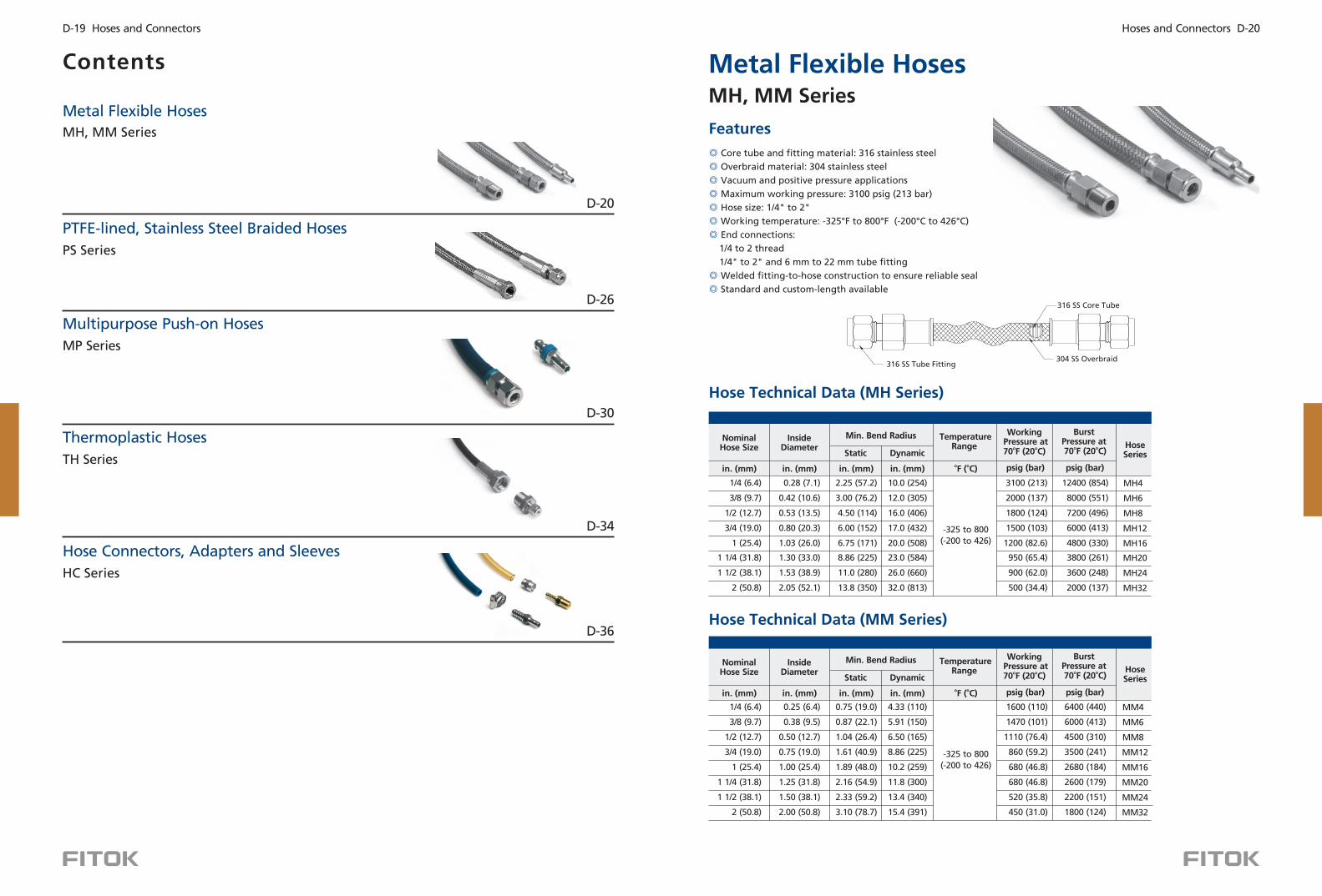
Core tube and fitting material: 316 stainless steel
Overbraid material: 304 stainless steel
Vacuum and positive pressure applications
Maximum working pressure: 3100 psig (213 bar)
Hose size: 1/4 to 2
End connections:
1/4 to 2 thread
1/4 to 2 and 6 mm to 22 mm tube fitting
Welded fitting-to-hose construction to ensure reliable seal
Standard and custom-length
" "
Working temperature: -325°F to 800°F (-200°C to 426°C)
" "
available
Features
Metal Flexible HosesMH, MM Series
Contents
D-26
D-30
D-34
Metal Flexible Hoses
PTFE-lined, Stainless Steel Braided Hoses
Multipurpose Push-on Hoses
Thermoplastic Hoses
Hose Connectors, Adapters and Sleeves
MH, MM Series
PS Series
MP Series
TH Series
D-36
HC Series
D-20
Hose Technical Data (MH Series)
Hose Technical Data (MM Series)
316 SS Core Tube
316 SS Tube Fitting304 SS Overbraid
InsideDiameter
in. ( )mm
0.25 (6.4)
0.38 (9.5)
0.50 (12.7)
0.75 (19.0)
1.00 (25.4)
1.25 (31.8)
1.50 (38.1)
2.00 (50.8)
in. ( )mm
0.75 (19.0)
0.87 (22.1)
1.04 (26.4)
1.61 (40.9)
1.89 (48.0)
2.16 (54.9)
2.33 (59.2)
3.10 (78.7)
Static
Min. Bend Radius
Dynamic
in. ( )mm
4.33 (110)
5.91 (150)
6.50 (165)
8.86 (225)
10.2 (259)
11.8 (300)
13.4 (340)
15.4 (391)
TemperatureRange
-325 to 800
(-200 to 426)
Working Pressure at
o o70 F (20 C)
psig ( )bar
1600 (110)
1470 (101)
1110 (76.4)
860 (59.2)
680 (46.8)
680 (46.8)
520 (35.8)
450 (31.0)
BurstPressure at
o o 70 F (20 C)
HoseSeries
6400 (440)
6000 (413)
4500 (310)
3500 (241)
2680 (184)
2600 (179)
2200 (151)
1800 (124)
MM4
MM6
MM8
MM12
MM16
MM20
MM24
MM32
psig ( )bar
NominalHose Size
1/4 (6.4)
3/8 (9.7)
1/2 (12.7)
3/4 (19.0)
1 (25.4)
1 1/4 (31.8)
1 1/2 (38.1)
2 (50.8)
in. ( )mmo oF ( C)
InsideDiameter
in. ( )mm
0.28 (7.1)
0.42 (10.6)
0.53 (13.5)
0.80 (20.3)
1.03 (26.0)
1.30 (33.0)
1.53 (38.9)
2.05 (52.1)
in. ( )mm
2.25 (57.2)
3.00 (76.2)
4.50 (114)
6.00 (152)
6.75 (171)
8.86 (225)
11.0 (280)
13.8 (350)
Static
Min. Bend Radius
Dynamic
in. ( )mm
10.0 (254)
12.0 (305)
16.0 (406)
17.0 (432)
20.0 (508)
23.0 (584)
26.0 (660)
32.0 (813)
TemperatureRange
-325 to 800
(-200 to 426)
Working Pressure at
o o70 F (20 C)
psig ( )bar
3100 (213)
2000 (137)
1800 (124)
1500 (103)
1200 (82.6)
950 (65.4)
900 (62.0)
500 (34.4)
BurstPressure at
o o 70 F (20 C)
HoseSeries
12400 (854)
8000 (551)
7200 (496)
6000 (413)
4800 (330)
3800 (261)
3600 (248)
2000 (137)
MH4
MH6
MH8
MH12
MH16
MH20
MH24
MH32
psig ( )bar
NominalHose Size
1/4 (6.4)
3/8 (9.7)
1/2 (12.7)
3/4 (19.0)
1 (25.4)
1 1/4 (31.8)
1 1/2 (38.1)
2 (50.8)
in. ( )mmo oF ( C)
Hoses and Connectors D-20D-19 Hoses and Connectors

Pressure vs. Temperature
The working pressure of the hose selected must not exceed the maximum pressure, including any pressure spikes of the system.
To determine actual working pressure ratings in accordance with pulsation, shock factors multiply by 0.5.
Pre
ssu
re (
b ar)
34.4
69.0
103
137
172
206
241
426
0
800
371
700
316
600
260
500
Temperature ( )°C
Temperature ( )°F
204
400
149
300
93
200
38
100
MH series
MM series
-200
-325
0
500
1000
1500
2000
2500
3000
3500
Pre
ssu
re (
p si
g)
-5 3Every FITOK metal flexible hose assembly is factory tested with helium to a maximum leak rate of 1 x 10 std cm /s.
FITOK metal flexible hose components are cleaned in accordance with FITOK standard cleaning (FC-01) for general
industrial procedures.
Shorter hoses are packed in cartons with suitable protective material, longer hoses are coiled, bagged and boxed
or crated.
Cleaning and Packaging
Testing
MH4
MH6MH8
MH12MH16
MH20MH24
MH32
Pre
ssu
re (
b ar)
34.4
69.0
103
137
0
426
800
371
700
316
600
260
500
Temperature ( )°C
Temperature ( )°F
204
400
149
300
93
200
38
100
-200
-325
500
1000
1500
2000
0
Pre
ssu
re (
p si
g)
MM4MM6
MM8
MM12
MM16 / MM20
MM24
MM32
Standard Assemblies
1. All dimensions are for reference only and are subject to change. For dimensions not shown above, please
contact the authorized representative or .
2. Types listed are standard. Other types are available upon request, refer to the ordering information.
FITOK Group
Tube Fitting to Male NPT End
Tube Adapter End
NominalHoseSize
in.
3/8
1/4
TubeAdapter
Size
in.
3/8
1/4
HoseSeries
MH6
MM6
MH4
MM4
in.(mm)
12 (305)
36 (914)
12 (305)
36 (914)
Overall
engthL Ordering Number
SS-MH6-FT6-F12
SS-MM6-FT6-F36
SS-MH4-FT4-F12
SS-MM4-FT4-F36
MinimumInside
Diameter
in.(mm)
0.27 (6.9)
0.16 (4.1)
0.27 (6.9)
0.16 (4.1)
MaximumOutside
Dimension
in.(mm)
1.01 (25.6)
0.81 (20.6)
0.91 (23.1)
0.76 (19.2)
Tube Fitting End
TubeFitting
Size
NominalHoseSize
in.in.
HoseSeries
OverallengthL Ordering Number
MinimumInside
Diameter
MaximumOutside
Dimension
in.(mm) in.(mm)
MH4
MM4
MH6
MM6
MH8
MM8
MH12
MM12
MH16
0.19 (4.8)
0.19 (4.8)
0.28 (7.1)
0.28 (7.1)
0.41 (10.4)
0.41 (10.4)
0.66 (16.0)
0.66 (16.0)
0.88 (22.4)
0.94 (23.8)
0.87 (22.0)
1.09 (27.7)
1.01 (25.7)
1.23 (31.3)
1.23 (31.3)
1.74 (44.2)
1.59 (40.5)
1.82 (46.3)
SS-MH4-FL4-F12
SS-MM4-FL4-F36
SS-MH6-FL6-F18
SS-MM6-FL6-F36
SS-MH8-FL8-F18
SS-MM8-FL8-F48
SS-MH12-FL12-F18
SS-MM12-FL12-F48
SS-MH16-FL16-F24
1/41/4
3/83/8
1/21/2
3/43/4
11
in.(mm)
12 (305)
36 (914)
18 (457)
36 (914)
18 (457)
48 (1220)
18 (457)
48 (1220)
24 (610)
TubeFitting
Size
NominalHoseSize
NPTSize
in.in.
HoseSeries
OverallLength Ordering Number
MinimumInside
Diameter
MaximumOutside
Dimension
in.(mm) in.(mm)
MH4
MM4
MH6
MM6
MH8
MM8
MH12
MM12
MH16
0.19 (4.8)
0.19 (4.8)
0.28 (7.1)
0.28 (7.1)
0.41 (10.4)
0.41 (10.4)
0.66 (16.0)
0.66 (16.0)
0.88 (22.4)
0.94 (23.8)
0.87 (22.0)
1.09 (27.7)
1.01 (25.7)
1.23 (31.3)
1.23 (31.3)
1.74 (44.2)
1.59 (40.5)
1.82 (46.3)
SS-MH4-FL4-NS4-F12
SS-MM4-FL4-NS4-F36
SS-MH6-FL6-NS6-F18
SS-MM6-FL6-NS6-F36
SS-MH8-FL8-NS8-F18
SS-MM8-FL8-NS8-F48
SS-MH12-FL12-NS12-F18
SS-MM12-FL12-NS12-F48
SS-MH16-FL16-NS16-F24
1/41/4
3/83/8
1/21/2
3/43/4
11
1/4
3/8
1/2
3/4
1
in. in.(mm)
12 (305)
36 (914)
18 (457)
36 (914)
18 (457)
48 (1220)
18 (457)
48 (1220)
24 (610)
Hoses and Connectors D-22D-21 Hoses and Connectors

End Connections
A
Tube Fittings
MinimumInside
Diameter
MaximumOutside
Diameter
0.19 (4.8)
0.28 (7.1)
0.28 (7.1)
0.41 (10.4)
0.50 (12.7)
0.63 (16.0)
0.88 (22.4)
1.09 (27.7)
1.34 (34.0)
1.88 (47.8)
4.8 (0.19)
6.4 (0.25)
7.9 (0.31)
9.7 (0.38)
0.94 (23.8)
0.94 (23.8)
1.09 (27.7)
1.23 (31.3)
1.23 (31.3)
1.74 (44.2)
1.82 (46.3)
2.23 (58.9)
2.61 (66.3)
3.48 (88.4)
20.6 (0.81)
20.6 (0.81)
31.3 (1.23)
38.8 (1.53)
End Connection Designator
NominalHose Size
FL4
FL6
FL6
FL8
FL10
FL12
FL16
FL20
FL24
FL32
ML6
ML8
ML10
ML12
in.
Dimensions
1/4
1/4
3/8
1/2
1/2
3/4
1
1 1/4
1 1/2
2
1/4
1/4
3/8
1/2
1.94 (49.3)
2.00 (50.8)
2.02 (51.3)
2.24 (56.9)
2.27 (57.7)
2.35 (59.7)
2.64 (67.1)
4.04 (103)
4.75 (121)
5.72 (145)
62.2 (2.45)
63.2 (2.49)
51.6 (2.03)
56.9 (2.24)
mm mm (in.)
A
TubeFitting
Size
1/4
3/8
3/8
1/2
5/8
3/4
1
1 1/4
1 1/2
2
6
8
10
12
in. in. (mm)
A
Tube Adapters
MinimumInside
Diameter
MaximumOutside
Diameter
0.16 (4.1)
0.27 (6.9)
0.37 (9.4)
0.58 (14.7)
0.80 (20.3)
4.1 (0.16)
7.1 (0.28)
8.9 (0.35)
0.81 (20.6)
1.01 (25.6)
1.23 (31.3)
1.53 (38.8)
1.82 (46.3)
20.6 (0.81)
25.6 (1.01)
31.3 (1.23)
End Connection Designator
NominalHose Size
FT4
FT6
FT8
FT12
FT16
MT6
MT10
MT12
in.
Dimensions
1/4
3/8
1/2
3/4
1
1/4
3/8
1/2
1.76 (44.7)
1.82 (46.2)
2.22 (56.4)
2.35 (59.7)
2.69 (68.3)
44.4 (1.75)
47.0 (1.85)
57.2 (2.25)
mm (in.)
A
TubeAdapter
Size
1/4
3/8
1/2
3/4
1
6
10
12
in.
in.
in. (mm)
A
Male FR Metal Gasket Face
Seal Fittings Swivel MinimumInside
Diameter
MaximumOutside
Diameter
0.18 (4.6)
0.40 (10.2)
0.65 (16.5)
0.87 (22.1)
0.81 (20.6)
1.23 (31.3)
1.52 (38.7)
1.53 (38.8)
End Connection Designator
NominalHose Size
SFR4
SFR8
SFR12
SFR16
FRSize
1/4
1/2
3/4
1
in. in. in. (mm)
Dimensions
1/4
1/2
3/4
1
2.60 (66.0)
2.83 (71.9)
4.19 (106)
4.80 (122)
A
Female FR Metal Gasket Face
Seal Fittings Swivel
Female Pipe Threads, NPT
Male Pipe Threads, NPT
MinimumInside
Diameter
MaximumOutside
Diameter
0.28 (7.1)
0.38 (9.7)
0.47 (11.9)
0.72 (18.3)
0.94 (23.9)
1.09 (27.7)
1.23 (31.3)
1.74 (44.2)
NPTSize
End Connection Designator
NominalHose Size
FNS4
FNS6
FNS8
FNS12
1/4
3/8
1/2
3/4
in. in. in. (mm)
Dimensions
1/4
3/8
1/2
3/4
1.81 (46.0)
1.87 (47.5)
2.18 (55.4)
2.21 (56.1)
A
MinimumInside
Diameter
MaximumOutside
Diameter
0.17 (4.3)
0.28 (7.1)
0.42 (10.7)
0.81 (20.6)
1.01 (25.6)
1.23 (31.3)
SwivelSize
End Connection Designator
NominalHose Size
SAN4
SAN6
SAN8
1/4
3/8
1/2
in. in. (mm)in.
Dimensions
1/4
3/8
1/2
1.87 (47.5)
1.98 (50.3)
2.25 (57.2)
A
MinimumInside
Diameter
MaximumOutside
Diameter
0.18 (4.6)
0.40 (10.2)
0.81 (20.6)
1.23 (31.3)
FOSize
End Connection Designator
NominalHose Size
SFFO4
SFFO8
1/4
1/2
in. in. (mm)in.
Dimensions
1/4
1/2
2.11 (53.6)
2.14 (54.4)
A
in. (mm)
MinimumInside
Diameter
MaximumOutside
Diameter
0.28 (7.1)
0.28 (7.1)
0.38 (9.7)
0.47 (11.9)
0.47 (11.9)
0.63 (16.0)
0.88 (22.4)
1.09 (27.7)
1.34 (34.0)
1.81 (46.0)
0.94 (23.9)
1.09 (27.7)
1.09 (27.7)
1.02 (25.8)
1.23 (31.3)
1.74 (44.2)
1.82 (46.3)
2.03 (51.6)
2.47 (62.6)
3.19 (81.0)
NPTSize
End Connection Designator
NominalHose Size
NS4
NS4
NS6
NS8
NS8
NS12
NS16
NS20
NS24
NS32
1/4
1/4
3/8
1/2
1/2
3/4
1
1 1/4
1 1/2
2
in. in.
Dimensions
1/4
3/8
3/8
1/4
1/2
3/4
1
1 1/4
1 1/2
2
1.80 (45.7)
1.81 (46.0)
1.81 (46.0)
1.99 (50.6)
2.15 (54.6)
2.22 (56.4)
2.54 (64.5)
3.06 (77.7)
3.72 (94.5)
4.19 (106)
A
Female FO O-Ring Face
Seal Fittings Swivel
A
A
A
A
oSAE 37 (JIC) Female Swivel
A
37
o
MinimumInside
Diameter
MaximumOutside
Diameter
0.18 (4.6)
0.40 (10.2)
0.65 (16.5)
0.87 (22.1)
0.87 (22.1)
1.23 (31.3)
1.74 (44.2)
2.03 (51.6)
FRSize
End Connection Designator
NominalHose Size
SFFR4
SFFR8
SFFR12
SFFR16
1/4
1/2
3/4
1
in. in. in. (mm)
Dimensions
1/4
1/2
3/4
1
2.00 (50.8)
2.16 (54.9)
4.19 (106)
4.80 (122)
A
End Connections
mm
in.
Hoses and Connectors D-24D-23 Hoses and Connectors

Example: SS-MH4-FT6-M710
SS: End connection material is 316 stainless steel.
MH4: MH series, hose size is 1/4 .
FT6: End 1 connection type and size is 3/8 tube adapter.
End 2 connection type and size is 3/8 tube adapter.
M710: Overall length is 710 mm.
"
"
"
◎
Lightweight construction for easy handling and installation
Core tube material: smooth virgin PTFE
Overbraid material: 304 stainless steel
Maximum working pressure: 3000 psig (207 bar)
Hose size: 1/4" to 1"
-65°F to 400°F (-53°C to 204°C)
Standard and custom-length available
◎
◎
◎
◎
◎
◎
Working temperature:
PTFE-lined, Stainless Steel Braided HosesPS Series
Features
Hose Technical Data
316 SS and other alloy end connections
Smooth Virgin PTFE Core Tube
304 SS Overbraid
End 1 and end 2 follow the orders and regulations below:
1. Metric Double Ferrules - Fractional Double Ferrules - Metric Tube Adapters - Fractional
Tube Adapters - NPT Threads - BSPT Threads - BSPP Threads -SAE/MS Parallel Threads -
37 Flare - Others
2. Put the sizes from the biggest down to the smallest if they are of the same type.
3. Put the female before male if they are of the same type and size.
in. ( )mmin. ( )mm
Min. Inside Bend Radius TemperatureRange
InsideDiameter
NominalHose Size
0.19 (4.8)
0.31 (7.9)
0.41 (10.3)
0.63 (15.9)
0.88 (22.2)
1/4 (6.4)
3/8 (9.5)
1/2 (12.7)
3/4 (19.0)
1 (25.4)
Static Dynamic
Working Pressure at
o o70 F (20 C)
Burst Pressure at
o o70 F (20 C)
psig ( )bar
1.5 (38 1).
3.5 (88 9).
4.5 (114)
6.0 (152)
9.0 (229)
2.0 (50.8)
5.0 (127)
6.0 (152)
7.5 (190)
11.3 (287)
-65 to 450
(-53 to 230)
3000 (206)
2500 (172)
2000 (137)
1500 (103)
1000 (68)
12000 (826)
10000 (690)
8000 (551)
6000 (413)
4000 (275)
in. ( )mm in. ( )mmo o
F ( C) psig ( )bar
Nominal Hose Size
End ConnectionMaterial
SS - MH4 FL6 NS6 F36 - - -
Hose End 1 Connection Type End 1 Connection SizeEnd 2 Connection
Type and Size
MM
MH
Mediumpressure hose
High pressure hose
6
3/8 (in.) or 6 mm
1/2 (in.) or 8 mm
5/8 (in.) or 10 mm
3/4 (in.) or 12 mm
M14 x 1.5
6
8
10
12
14
4
1 (in.) or 16 mm16
M18 x 1.518
M20 x 1.520
Same as End 1
Specify in the same way as the end 1 connection type and size
Overall Length
XX in.
XX mm
FXX
MXX1/4 (in.)
4 1/4"
3/8"
3 3/16 (in.) SS 316 SS
904L SS904L
1 1/4"
1 1/
8
12
16
1/2''
3/4"
Fractional Tube Fitting
Fractional Tube Adapter
Female JIC 37Flare Swivel
°
Female NPT
Female BSPT
Male BSPT
Male NPT
Female Metric Thread(for RG gasket)
Male Metric Thread(for RG gasket)
Metric Tube Fitting
Metric TubeAdapter
Male JIC 37Flare
°
Female FR FittingSwivel
Male FR FittingSwivel
FL
ML
FT
FNS
FRT
RT
FMS
MS
NS
MT
AN
SFFR
SFR
SAN
20
24
32
1"
2"
2"
Note: "Part Number Description" is used for composition
rules of FITOK product model, Not suitable for
specific product part number selection, not random
combinations. If in doubt, please contact FITOK
group or authorized agent.
Part Number Description
Hoses and Connectors D-26D-25 Hoses and Connectors

Pressure vs. Temperature
Testing
Every FITOK PTFE-lined hose assembly is factory tested with pure water at 1.5 times the maximum working pressure.
Cleaning and Packaging
FITOK PTFE-lined hose components are cleaned in accordance with FITOK standard cleaning (FC-01) for general
industrial procedures.
Shorter hoses are packed in cartons with suitable protective material, longer hoses are coiled, bagged and boxed
or crated.
PTFE-lined Hose Standard Assemblies
Tube Adapters
1. All dimensions are for reference only and are subject to change. For dimensions
not shown above, please contact the authorized representative or .
2. Sizes and types listed are standard. Other sizes and types are available on
request, refer to the ordering information.
FITOK Group
NominalHoseSize
in.
Ordering Number
in. in.(mm) in.(mm)in.(mm)
SS-PS4-FT4-F6
SS-PS4-FT4-F12
SS-PS4-FT4-F18
SS-PS4-FT4-F24
SS-PS4-FT4-F36
SS-PS4-FT4-F48
SS-PS4-FT4-F60
SS-PS4-FT4-F72
SS-PS4-FT4-F120
SS-PS6-FT6-F12
SS-PS6-FT6-F18
SS-PS6-FT6-F24
SS-PS6-FT6-F36
SS-PS6-FT6-F48
SS-PS6-FT6-F60
SS-PS6-FT6-F72
SS-PS6-FT6-F96
SS-PS6-FT6-F120
SS-PS8-FT8-F12
SS-PS8-FT8-F24
SS-PS8-FT8-F36
SS-PS8-FT8-F48
SS-PS8-FT8-F60
SS-PS8-FT8-F72
SS-PS12-FT12-F24
SS-PS12-FT12-F36
SS-PS16-FT16-F36
SS-PS16-FT16-F48
SS-PS4-MT6-F12
SS-PS4-MT6-F24
SS-PS4-MT6-F36
SS-PS8-MT12-F24
SS-PS8-MT12-F36
1/4 1/4 0.16(4.1)
0.54(13.7)
3/8 3/80.27(6.9)
0.73(18.5)
1/2 0.36(9.1)
0.86(21.8)
1/2
3/40.53
(13.5)1.04
(26.4)3/4
10.80
(20.3)1.36
(34.5)1
in. mm in.(mm) in.(mm)
60.16(4.1)
0.54(13.7)1/4
120.33(8.4)
0.86(21.8)1/2
OverallLength
TubeAdapter
Size
MinimumInside
Diameter
MaximumOutside
Diameter
in.(mm)
6.0 (153)
12.0 (305)
18.0 (458)
24.0 (610)
36.0 (915)
48.0 (1220)
60.0 (1530)
72.0 (1829)
120.0 (3050)
12.0 (305)
18.0 (458)
24.0 (610)
36.0 (915)
48.0 (1220)
60.0 (1530)
72.0 (1829)
96.0 (2439)
120.0 (3050)
12.0 (305)
24.0 (610)
36.0 (915)
48.0 (1220)
60.0 (1530)
72.0 (1829)
24.0 (610)
36.0 (915)
36.0 (915)
48.0 (1220)
12.0 (305)
24.0 (610)
36.0 (915)
24.0 (610)
36.0 (915)
Hoses and Connectors D-28D-27 Hoses and Connectors
Temperature ( )°C
Temperature ( )°F
Pre
ssu
re (
psi
g)
Pre
ssu
re (
bar)
100 200 300 400 600
0
300
600
900
1200
1500
1800
2100
2400
2700
3000
3300
0
20 7.
41 4.
62 1.
82 8.
103 4.
124 1.
144 8.
165 5.
186 2.
206 9.
227.6
38 93 149 204 316
PS4
PS6
PS8
PS12
PS16
-100
-73.3

302 S
tain
less
Ste
el
Spri
ng
Gu
ard
Cle
ar
PV
C C
ove
rP SP
PS
PTFE
ho
se
(hig
h-p
ress
ure
)
No
min
al
Ho
se S
ize
Ho
se
SS
PS4
FL6
FT6
M1000
-
-
-
-
- P
F2
En
d 1
Co
nn
ect
ion
Siz
eEn
d C
on
nect
ion
Mate
rial
Overa
ll
Len
gth
SS
316 S
S
A20
Allo
y 20
S4
304 S
S
INC
HC
Allo
y 600
Allo
y C
-276
TI
Tit
an
ium
4 6 8
12
16
1/4
"
3/8
"
1/2
''
3/4
"
1"
En
d 1
Co
nn
ect
ion
Typ
e
4 6 8
12
14
16
18
20
1/4
(in
.)
3/8
(in
.) o
r 6 m
m
5/8
(in
.) o
r 10 m
m
3/4
(in
.) o
r 12 m
m
M14 x
1.5
1 (
in.)
or
16 m
m
M18 x
1.5
M20 x
1.5
10
XX
in
.
XX
mm
FXX
MX
X
Exa
mp
le:
SS-P
S4-S
AN
4-M
500
SS
: E
nd
co
nn
ect
ion
ma
teri
al
is 3
16
sta
inle
ss s
tee
l.
PS
4:
PS s
eri
es,
ho
se i
nsi
de
dia
me
ter
is 3
/16
.
SA
N4
: E
nd
1 c
on
ne
ctio
n t
ype
an
d s
ize
is
1/4
o
fi
ttin
g s
ize
, fe
ma
le J
IC 3
7 f
lare
sw
ive
l.
E
nd
2 c
on
ne
ctio
n t
yp
e a
nd
siz
e i
s 1
/4
o
fitt
ing
siz
e,
fem
ale
JIC
37
fla
re s
wiv
el.
M5
00
: O
ve
rall
le
ng
th i
s 5
00
mm
.
"
" "
En
d 2
Co
nn
ect
ion
Typ
e a
nd
Siz
e
Sam
e a
s En
d 1
Speci
fy in
th
e
sam
e w
ay
as
the
en
d 1
co
nn
ect
ion
ty
pe a
nd
siz
e
Op
tio
n
1/2
()
8
in.
or
mm
1. O
pti
on
s an
d a
ccess
ori
es
do
no
t ch
an
ge h
ose
tech
nic
al d
ata
. H
ose
op
era
tin
g
p
ara
mete
rs m
ust
be c
on
sid
ere
d w
hen
sele
ctin
g a
co
ver.
2.
PV
C c
ove
r re
sist
s ab
rasi
on
.
3. 302 s
tain
less
ste
el sp
rin
g g
uard
co
vers
en
tire
ho
se t
o p
rote
ct a
gain
st
kin
kin
g a
nd
ab
rasi
on
.
4.
Luci
d
To
ord
er
a h
ose
ass
em
bly
wit
h s
peci
al cl
ean
ing
an
d p
ack
ag
ing
(FC
-02),
fo
llo
win
g
A
STM
G93 le
vel C
, ad
d -
F2 a
s a s
uff
ix t
o t
he o
rderi
ng
nu
mb
er.
E
xam
ple
: SS-P
S4-F
T4-F
24-F
2.
En
d 1
an
d e
nd
2 f
ollo
w t
he o
rders
an
d r
eg
ula
tio
ns
belo
w:
1. M
etr
ic D
ou
ble
Ferr
ule
s -
Fract
ion
al D
ou
ble
Ferr
ule
s -
Metr
ic T
ub
e A
dap
ters
- F
ract
ion
al
T
ub
e A
dap
ters
- N
PT T
hre
ad
s -
BSP
T T
hre
ad
s -
BSP
P T
hre
ad
s -
SAE/M
S Para
llel
Th
read
s -
3
7
Flare
- O
thers
2. Pu
t th
e s
izes
fro
m t
he b
igg
est
do
wn
to
th
e s
mallest
if
they
are
of
the s
am
e t
ype.
3. Pu
t th
e f
em
ale
befo
re m
ale
if
they
are
of
the s
am
e t
ype a
nd
siz
e.
Cle
an
ing
an
d
Pack
ag
ing
FC-0
1
FC-0
2F2
904L
904L
SS
Fem
ale
(f
or
RG
gask
et)
Metr
ic T
hre
ad
Male
(f
or
RG
)
Metr
ic T
hre
ad
gask
et
Metr
ic T
ub
e A
dap
ter
Fem
ale
JIC
37
Flare
Swiv
el
°
Fem
ale
Metr
ic T
hre
ad
Sw
ivel
(fo
r R
G g
ask
et)
Fem
ale
BSP
P S
wiv
el
(fo
r R
G
)g
ask
et
Fract
ion
al
Tu
be
Fitt
ing
Metr
ic T
ub
e F
itti
ng
Fract
ion
al
Tu
be
Ad
ap
ter
Male
JIC
37
Flare
°
Fem
ale
NPT
Male
NPT
Fem
ale
BSP
T
Male
BSP
T
FNS
NS
FRT
RT
FMS
MS
FLML
FTMT
AN
SA
N
SM
S
SR
G
Part
Nu
mb
er
Desc
rip
tio
n
No
te: "Part
Nu
mb
er
Desc
rip
tio
n" is
use
d f
or
com
po
siti
on
ru
les
of
FITO
K p
rod
uct
mo
del, N
ot
suit
ab
le f
or
sp
eci
fic
pro
du
ct p
art
nu
mb
er
sele
ctio
n, n
ot
ran
do
m
co
mb
inati
on
s. If
in d
ou
bt,
ple
ase
co
nta
ct F
ITO
K
g
rou
p o
r au
tho
rize
d a
gen
t.
Hoses and Connectors D-30D-29 Hoses and Connectors
0
3.4
6.8
10.3
13.7
17.2
20.7
24.1
Pre
ssu
re (
bar)
Pre
ssu
re (
psi
g)
350653720-40
300
250
200
150
100
50
-400
10070
88
150 200
Temperature ( )°C
Temperature ( )°F
TemperatureRange
in. ( )mmin. ( )mm
InsideDiameter
Nominal Hose Size
Min. InsideBend Radius
Working Pressure at
o-40 to 70 F
o(-40 to 20 C)
Min. Burst Pressure
o oat 70 F (20 C)
psig (bar)
2.50 (63.5)
3.00 (76.2)
5.00 (127)
7.00 (178)
0.26 (6.6)
0.39 (9.9)
0.50 (12.7)
0.76 (19.3)
1/4 (6.4)
3/8 (9.5)
1/2 (12.7)
3/4 (19.0)
-40 to 200
(-40 to 93)300 (20.6) 1200 (82.7)
psig (bar)in. ( )mm ° °F( C)
◎
◎
◎
◎
◎
◎
◎
◎
◎
◎
Cover: weatherproof, abrasion withstanding and oil-resistant synthetic rubber
Reinforcement: single-braid high-strength synthetic fiber woven for maximum
strength and end connection retention
Core tube: highly oil-resistant rubber
Hose colors: blue, black, green, gray, red and yellow
Maximum working pressure: 300 psig (20.7 bar)
Hose size: 1/4 to 3/4
-40 F to 190 F (-40 C to 88 C)
End connection materials: stainless steel and brass
End connections reusable
Custom-length
" "
° ° ° °
available
Working temperature:
Features
Hose Technical Data Pressure vs. Temperature
Multipurpose Push-on HosesMP Series
Synthetic Rubber
Synthetic Rubber Tube
One High-strength Synthetic Yarn Laid
◎ Do not reuse hose.
Caution:
Testing
Every FITOK multipurpose push-on hose assembly is factory tested with pure water at 1.5 times the maximum working pressure.
Cleaning and Packaging
FITOK multipurpose push-on hose components are cleaned in accordance with FITOK standard cleaning (FC-01) forgeneral industrial
procedures.
Shorter hoses are packed in cartons with suitable protective material, longer hoses are coiled, bagged and boxed or crated.

Multipurpose Push-on Hose End Connections
Tube Fittings
A
B
NominalHoseSize
BasicOrdering Number
TubeFitting
Size
-MP4-FL4
-MP6-FL6
-MP8-FL8
A BMinimum
InsideDiameter
MaximumOutside
Diameter
1/4
3/8
1/2
1/4
3/8
1/2
1.97 (50.0)
2.11 (53.6)
2.47 (62.7)
1.21 (30.7)
1.24 (31.5)
1.42 (36.1)
0.16 (4.1)
0.27 (6.9)
0.37 (9.5)
0.67 (17.0)
0.87 (22.1)
1.02 (25.8)
in. in.
Dimensions, in.(mm)
Tube Adapters
A
B
Male NPT
A
B
Male BSPT
B
A
MinimumInside
Diameter
MaximumOutside
Diameter
Unions
A
B
NominalHose Size
BasicOrdering Number
-MP4-4
-MP6-6
-MP8-8
-MP12-12
1/4
3/8
1/2
3/4
in.
2.07 (52.6)
2.25 (57.2)
2.61 (69.8)
3.85 (97.8)
0.43 (11.4)
0.40 (12)
0.40 (14)
0.47 (12.0)
0.16 (4.1)
0.27 (6.9)
0.37 (9.5)
0.61 (15.6)
0.67 (17.0)
0.83 (21.1)
0.96 (24.5)
1.23 (31.3)
A B
Example: MP-8-F60-BK
MP: Hose series
8: Hose size is 1/2''.
F60: Overall length is 60 ."
BK: Hose color is black.
Hose Part aNumber Description
MP 4 F36 BK - - -
Hose Series
4
6
8
12
1/4(6.4mm)
"
3/8(9.5 mm)
"
1/2(12.7 mm)
''
3/4(19.0 mm)
"
Overall Length
XX in.
XX mm
FXX
MXX
MP
Hose Color
Blue
Black
Red
Green
Gray
BK
RD
GR
GY
YellowYW
Nominal Hose Size
MinimumInside
Diameter
MaximumOutside
Diameter
NominalHose Size
BasicOrdering Number
NPT Size
-MP4-NS4
-MP6-NS4
-MP6-NS6
-MP8-NS8
-MP12-NS12
1/4
3/8
3/8
1/2
3/4
in.
1/4
1/4
3/8
1/2
3/4
1.68 (42.7)
1.80 (45.7)
1.80 (45.7)
2.19 (55.6)
2.81 (71.4)
0.92 (23.4)
0.93 (23.6)
0.93 (23.6)
1.14 (29.0)
1.14 (29.0)
0.16 (4.1)
0.27 (6.9)
0.27 (6.9)
0.37 (9.5)
0.61 (15.6)
0.67 (17.0)
0.83 (21.1)
0.83 (21.1)
1.02 (25.9)
1.31 (33.3)
A B
Dimensions, in.(mm)
MinimumInside
Diameter
MaximumOutside
Diameter
0.15 (3.8)
0.24 (6.1)
0.34 (8.7)
0.57 (14.5)
3.8 (0.15)
4.1 (0.16)
5.6 (0.22)
6.9 (0.27)
8.1 (0.32)
8.6 (0.34)
0.67 (17.0)
0.83 (21.1)
0.98 (24.9)
1.23 (31.3)
17.0 (0.67)
17.0 (0.67)
21.1 (0.83)
21.1 (0.83)
24.9 (0.98)
31.3 (1.23)
NominalHoseSize
BasicOrdering Number
TubeAdapter
Size
-MP4-FT4
-MP6-FT6
-MP8-FT8
-MP12-FT12
-MP4-MT6
-MP4-MT8
-MP6-MT8
-MP6-MT10
-MP8-MT12
-MP12-MT18
1/4
3/8
1/2
3/4
1/4
1/4
3/8
3/8
1/2
3/4
in. in.
1/4
3/8
1/2
3/4
6
8
8
10
12
18
1.93 (49.0)
2.03 (51.6)
2.47 (62.7)
3.14 (79.8)
49.0 (1.93)
48.8 (1.92)
52.1 (2.05)
51.6 (2.03)
62.7 (2.47)
79.8 (3.14)
in. mm mm(in.)
1.17 (29.7)
1.16 (29.5)
1.42 (36.1)
1.48 (37.6)
29.7 (1.17)
29.5 (1.16)
30.0 (1.18)
29.5 (1.16)
36.1 (1.42)
37.3 (1.47)
A B
Dimensions, in.(mm)
MinimumInside
Diameter
MaximumOutside
Diameter
NominalHose Size
BasicOrdering Number
BSPT Size
-MP4-RT4
-MP6-RT4
-MP6-RT6
-MP8-RT8
-MP12-RT12
1/4
3/8
3/8
1/2
3/4
in.
1/4
1/4
3/8
1/2
3/4
1.68 (42.7)
1.80 (45.7)
1.80 (45.7)
2.19 (55.6)
2.81 (71.4)
0.92 (23.4)
0.93 (23.6)
0.93 (23.6)
1.14 (29.0)
1.14 (29.0)
0.16 (4.1)
0.27 (6.9)
0.27 (6.9)
0.37 (9.5)
0.61 (15.6)
A B
Dimensions, in.(mm)
Dimensions, in.(mm)
0.67 (17.0)
0.83 (21.1)
0.83 (21.1)
1.02 (25.9)
1.31 (33.3)
Note: "Part Number Description" is used for composition
rules of FITOK product model, Not suitable for
specific product part number selection, not random
combinations. If in doubt, please contact FITOK
group or authorized agent.
Hoses and Connectors D-32D-31 Hoses and Connectors

◎
◎
◎
◎
◎
◎
◎
◎
◎
Polyurethane cover: resists oil, weather and abrasion
Reinforcement: double-braid high-strength synthetic fiber
Core tube: nylon
Maximum working pressure: 5000 psig (345 bar)
Hose size: 3/16 to 1
-40 F to 200 F (-40 C to 93 C)
End connections: 1/4 to 1 thread, 1/4 to 1 and 6 mm to 22 mm tube fitting
End connection materials: stainless steel, brass and carbon steel
Custom-length
" "
° ° ° °
" "
available
Working temperature:
Features
Thermoplastic HosesTH Series
Polyurethane Cover Fiber Reinforcement
Core Tube
Thermoplastic Hydraulic Hose (SAE 100R8)
Hose Series
Min. InsideBend
Radius Specification
NominalHose Size
InsideDiameter
Working Pressure at
o o70 F (20 C)
Min. Burst Pressure
o oat 70 F (20 C)
TemperatureRange
o oF ( C)
-40 to 200(-40 to 93)
SAE J517100R8
psig bar( )psig bar( )in. ( )mm in. ( )mm in. ( )mm
Thermoplastic Hydraulic Hose (SAE 100R7)
in. ( )mm in. ( )mm in. ( )mm
Hose Series
Min. InsideBend
Radius SpecificationNominal
Hose Size
TH3
TH4
TH5
TH6
TH8
InsideDiameter
Working Pressure at
o o70 F (20 C)
Min. Burst Pressure
o oat 70 F (20 C)
psig bar( )
TemperatureRange
o oF ( C)
1.58 (40)
1.97 (50)
2.36 (60)
2.95 (75)
3.74 (95)
-40 to 200(-40 to 93)
SAE J517100R7
psig bar( )
Technical Data
5000 (344)
5000 (344)
4000 (275)
3500 (241)
2250 (155)
2000 (137)
2.00 (50.8)
2.00 (50.8)
2.50 (63.5)
4.00 (102)
6.50 (165)
10.0 (254)
12000 (828)
11000 (758)
10000 (690)
9000 (620)
8000 (551)
3000 (207)
2750 (189)
2500 (173)
2250 (155)
2000 (137)
20000 (1378)
20000 (1378)
16000 (1102)
14000 (964)
9000 (620)
8000 (551)
0.19 (4.8)
0.25 (6.4)
0.38 (9.8)
0.50 (12.7)
0.75 (19.0)
1.00 (25.4)
0.19 (4.8)
0.25 (6.4)
0.31 (7.9)
0.38 (9.8)
0.50 (12.7)
TH3
TH4
TH6
TH8
TH12
TH16
3/16 (4.8)
1/4 (6.4)
3/8 (9.6)
1/2 (12.7)
3/4 (19.0)
1 (25.4)
3/16 (4.8)
1/4 (6.4)
5/16 (8.0)
3/8 (9.6)
1/2 (12.7)
Mu
ltip
urp
ose
Pu
sh-O
n H
ose
Cu
sto
m A
ssem
blie
s
Exa
mp
le:
SS-M
P4-F
T4-F
28-B
K
SS
: E
nd
co
nn
ect
ion
ma
teri
al
is 3
16
sta
inle
ss s
tee
l.
MP4
: M
P s
eri
es,
ho
se s
ize
is
1/4
".
FT
4:
En
d 1
co
nn
ect
ion
typ
e a
nd
siz
e i
s 1
/4"
tu
be
ad
ap
ter.
En
d 2
co
nn
ect
ion
typ
e a
nd
siz
e i
s 1
/4"
tu
be
ad
ap
ter.
F2
8:
Ove
rall
le
ng
th i
s 2
8"
.
BK
: H
ose
co
lor
is b
lack
.
En
d 1
an
d e
nd
2 f
ollo
w t
he o
rders
an
d r
eg
ula
tio
ns
belo
w:
1. M
etr
ic D
ou
ble
Ferr
ule
s -
Fract
ion
al D
ou
ble
Ferr
ule
s -
Metr
ic T
ub
e A
dap
ters
- F
ract
ion
al
T
ub
e A
dap
ters
- N
PT T
hre
ad
s -
BSP
T T
hre
ad
s -
BSP
P T
hre
ad
s -
SAE/M
S Para
llel Th
read
s -
3
7 F
lare
- O
thers
2. Pu
t th
e s
izes
fro
m t
he b
igg
est
do
wn
to
th
e s
mallest
if
they
are
of
the s
am
e t
ype.
3. Pu
t th
e f
em
ale
befo
re m
ale
if
they
are
of
the s
am
e t
ype a
nd
siz
e.
°
En
d C
on
nect
ion
Mate
rial
Ho
se S
eri
es
En
d 1
Co
nn
ect
ion
Typ
eEn
d 1
Co
nn
ect
ion
Siz
eEn
d 2
Co
nn
ect
ion
Typ
e a
nd
Siz
e
MP4
MP6
MP8
MP12
1/4
(6.4
mm
)"
3/8
(9.5
mm
)"
1/2
(12.7
mm
)''
3/4
(19.0
mm
)"
1/4
(in
.)
3/8
(in
.) o
r 6 m
m
1/2
(in
.) o
r 8 m
m
10 m
m
3/4
(in
.) o
r 12 m
m
18 m
m
6 8
10
12
184
Sam
e a
s En
d 1
Speci
fy in
th
e
sam
e w
ay
as
the
en
d 1
co
nn
ect
ion
ty
pe a
nd
siz
e
Overa
ll L
en
gth
XX
in
.
XX
mm
FXX
MX
X
SS
316 S
S
BB
rass
S4
304 S
S
Fract
ion
al
Tu
be F
itti
ng
Male
NPT
FLML
FTMT
NS
RT
Metr
ic
Tu
be F
itti
ng
Frac
tion
al T
ube
Ada
pter
Metr
ic T
ub
eA
dap
ter
Male
BSP
T
Ho
se C
olo
r
Blu
e
Bla
ck
Red
Gre
en
Gra
y
BK
RD
GR
GY
SSM
P4
4FT
4F3
6B
K -
-
-
-
-
FL
Yello
wY
W
904L
904L
SS
TestingEvery FITOK thermoplastic hose assembly is factory tested with pure water at 1.5 times the maximum working pressure.
Cleaning and Packaging
FITOK thermoplastic hose components are cleaned in accordance with FITOK standard cleaning (FC-01) for general industrial procedures.
Shorter hoses are packed in cartons with suitable protective material, longer hoses are coiled, bagged and boxed or crated.
Part
aN
um
ber
Desc
rip
tio
n
No
te: "Part
Nu
mb
er
Desc
rip
tio
n" is
use
d f
or
com
po
siti
on
ru
les
of
FITO
K p
rod
uct
mo
del, N
ot
suit
ab
le f
or
sp
eci
fic
pro
du
ct p
art
nu
mb
er
sele
ctio
n,
no
t ra
nd
om
co
mb
inati
on
s. If
in d
ou
bt,
ple
ase
co
nta
ct F
ITO
K
g
rou
p o
r au
tho
rize
d a
gen
t.
Hoses and Connectors D-34D-33 Hoses and Connectors

◎
◎
◎
◎
◎
Used to connect soft plastic or rubber tubing.
Working pressures and are wider
than those of the connected hoses.
Stainless steel or brass is available.
Shank design holds tubing inside diameter securely.
Hose connectors are reusable.
working temperatures
Features
Hose Connectors and SleevesHC Series
Th
erm
op
last
ic H
ose
Ass
em
blie
s
Hose Connectors
Tube Fittings
Tube Adapters
F
L
1/8
1/4
1/4
3/8
1/4
1/4
3/8
3/8
3/4
1
-HC-F2-FT2
-HC-F2-FT4
-HC-F4-FT4
-HC-F4-FT6
-HC-F5-FT4
-HC-F6-FT4
-HC-F6-FT6
-HC-F6-FT8
-HC-F8-FT6
-HC-F8-FT8
-HC-F12-FT12
-HC-F16-FT16
1/2
1/2
1/8
1/4
5/16
3/8
3/4
1
1/2
Hose ID
in.
Basic
Ordering
Number
Tube Size
in.
0.08 (2.0)
0.09 (2.3)
0.19 (4.8)
0.19 (4.8)
0.19 (4.8)
0.19 (4.8)
0.30 (7.6)
0.28 (7.1)
0.38 (9.7)
0.63 (16.0)
0.80 (20.3)
0.28 (7.1)
in.(mm)
MinimumInside
Diameter
1.37 (34.8)
1.47 (37.3)
1.86 (47.2)
1.92 (48.8)
1.94 (49.3)
1.94 (49.3)
2.26 (57.4)
2.07 (52.6)
2.33 (59.2)
2.50 (63.5)
3.03 (77.0)
2.00 (50.8)
in.(mm)
L
11/16
11/16
13/16
5/16
3/8
7/16
7/16
7/16
9/16
5/8
1 3/8
9/16
in.
F
Dimensions
mm ( )in.
0.08 (2.0)
0.09 (2.3)
0.19 (4.8)
0.19 (4.8)
0.28 (7.1)
0.38 (9.7)
4.8 (0.19)
6.4 (0.25)
6.4 (0.25)
7.9 (0.31)
9.7 (0.38)
mm
14
1.42 (36.1)
1.81 (46.0)
1.92 (48.8)
1.99 (50.6)
2.06 (52.3)
2.24 (56.9)
49.5 (1.95)
49.8 (1.96)
51.6 (2.03)
52.3 (2.06)
57.4 (2.26)
7/16
7/16
9/16
9/16
3/4
7/8
16
18
19
22
mm ( )in.
Hose ID
mm
1/8
1/4
3/8
1/2
6
8
10
12
in.
Tube Size
mm
1/8
1/8
1/4
1/4
3/8
1/2
6
8
10
10
12
in. in.(mm) in.(mm)in.
MinimumInside
DiameterLF
Dimensions
-HC-F2-FL2
-HC-F4-FL2
-HC-F4-FL4
-HC-F6-FL4
-HC-F6-FL6
-HC-F8-FL8
-HC-M6-ML6
-HC-M8-ML8
-HC-M8-ML10
-HC-M10-ML10
-HC-M12-ML12
BasicOrdering Number
SS
316 S
S
CS
S4
Carb
on
Ste
el
304 S
S
En
d C
on
nect
ion
Mate
rial
Ho
se S
eri
es
SST
H4
FL4
SAN
4M
1000
R7
-
-
-
-
-
En
d 1
Co
nn
ect
ion
Typ
eEn
d 1
Co
nn
ect
ion
Siz
eEn
d 2
Co
nn
ect
ion
Typ
e a
nd
Siz
e
TH
3
TH
4
TH
5
TH
6
TH
8
3/1
6(4
.8 m
m)
"
1/4
(6.4
mm
)"
5/1
6(7
.9 m
m)
"
3/8
(9.5
mm
)"
1/4
(in
.)
3/8
(in
.) o
r 6 m
m
1/2
(in
.) o
r 8 m
m
5/8
(in
.) o
r 10 m
m
3/4
(in
.) o
r 12 m
m
6 8
10
124
1 (
in.)
or
16 m
m16
Sam
e a
s En
d 1
Speci
fy in
th
e
sam
e w
ay
as
the
en
d 1
co
nn
ect
ion
typ
e a
nd
siz
e
Overa
ll
Len
gth
XX
in
.
XX
mm
FXX
MX
X
100R
7
100R
8
R7
R8Ho
se C
od
e
Exa
mp
le:
S S
-TH
4-F
L4-N
S4-F
36-R
7
SS
: E
nd
co
nn
ect
ion
ma
teri
al
is 3
16
sta
inle
ss s
tee
l.
TH
4: T
H s
eri
es,
ho
se s
ize
is
1/4
FL4
: En
d 1
co
nn
ect
ion
typ
e a
nd
siz
e i
s 1
/4 t
ub
e f
itti
ng
.
NS
4 : E
nd
2 c
on
ne
ctio
n t
yp
e a
nd
siz
e i
s 1
/4 m
ale
NP
T.
F3
6 :
Ove
rall
le
ng
th i
s 3
6
R7
: SA
E J
51
7 1
00
R7
.
"
"
"
1/2
(12.7
mm
)"
T
ub
e A
dap
ters
- N
PT T
hre
ad
s -
BSP
T T
hre
ad
s -
BSP
P T
hre
ad
s -
SAE/M
S Para
llel
Th
read
s -
En
d 1
an
d e
nd
2 f
ollo
w t
he o
rders
an
d r
eg
ula
tio
ns
belo
w:
1. M
etr
ic D
ou
ble
Ferr
ule
s -
Fract
ion
al D
ou
ble
Ferr
ule
s -
Metr
ic T
ub
e A
dap
ters
- F
ract
ion
al
3
7Fl
are
- O
thers
°
2. Pu
t th
e s
izes
fro
m t
he b
igg
est
do
wn
to
th
e s
mallest
if
they
are
of
the s
am
e t
ype.
3. Pu
t th
e f
em
ale
befo
re m
ale
if
they
are
of
the s
am
e t
ype a
nd
siz
e.
904L
904L
SS
Fem
ale
(f
or
RG
gask
et)
Metr
ic T
hre
ad
Male
(f
or
RG
)
Metr
ic T
hre
ad
gask
et
Metr
ic T
ub
e A
dap
ter
Fem
ale
JIC
37
Flare
Swiv
el
o
Fem
ale
Metr
ic T
hre
ad
Sw
ivel (f
or
RG
gask
et)
Fem
ale
BSP
P S
wiv
el
(fo
r R
G
)g
ask
et
Fract
ion
al Tu
be
Fitt
ing
Metr
ic T
ub
e F
itti
ng
Fract
ion
al Tu
be
Ad
ap
ter
Male
NPT
Male
BSP
T
NS
RT
FMS
MS
FLML
FTMT
SA
N
SM
S
SR
G
L
F
Part
aN
um
ber
Desc
rip
tio
n
No
te: "Part
Nu
mb
er
Desc
rip
tio
n" is
use
d f
or
co
mp
osi
tio
n r
ule
s o
f FI
TO
K p
rod
uct
m
od
el, N
ot
suit
ab
le f
or
speci
fic
pro
du
ct
p
art
nu
mb
er
sele
ctio
n, n
ot
ran
do
m
co
mb
inati
on
s. If
in d
ou
bt,
ple
ase
co
nta
ct
FI
TO
K g
rou
p o
r au
tho
rize
d a
gen
t.
Hoses and Connectors D-36D-35 Hoses and Connectors
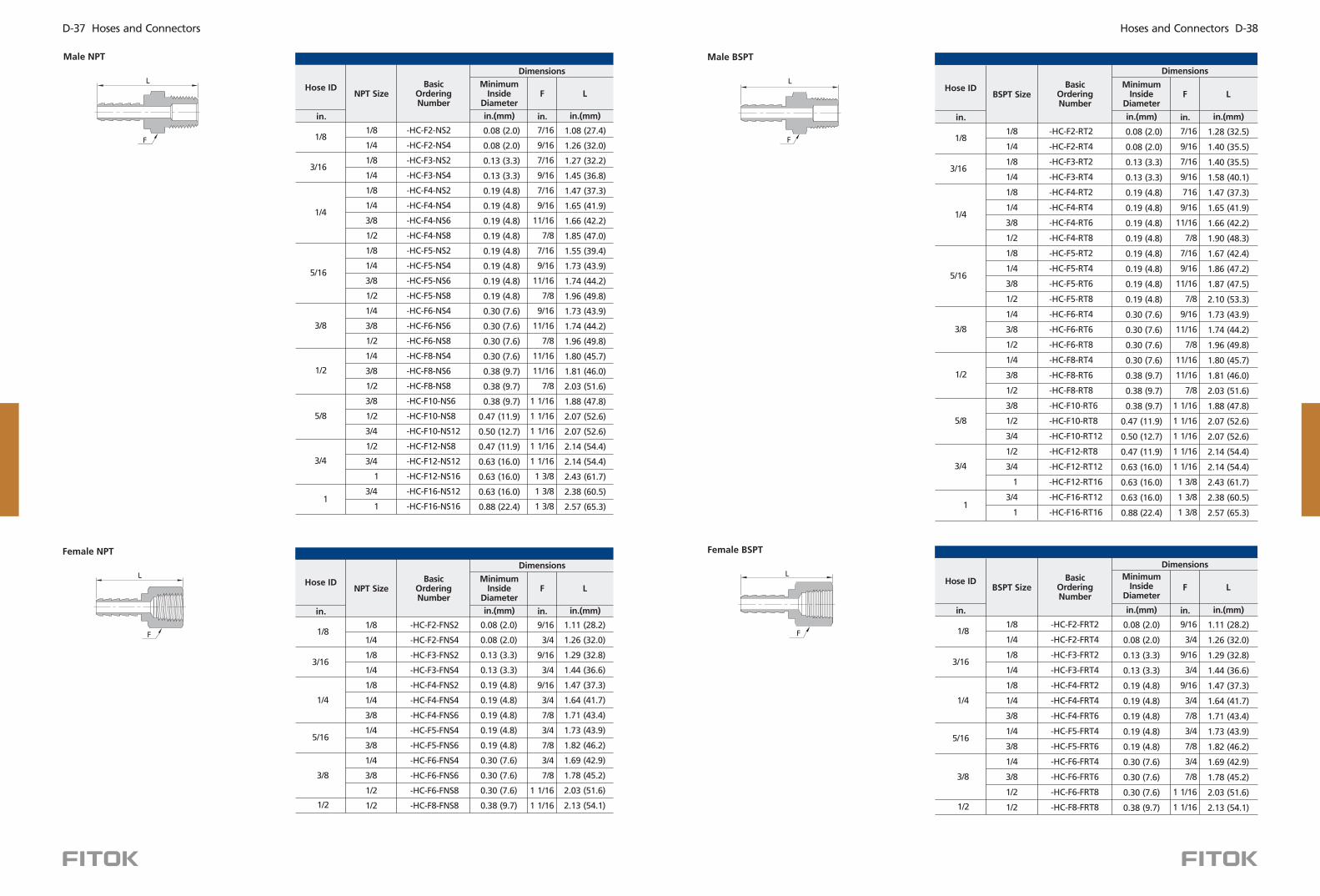
-HC-F2-NS2
-HC-F2-NS4
-HC-F3-NS2
-HC-F3-NS4
-HC-F4-NS2
-HC-F4-NS4
-HC-F4-NS6
-HC-F4-NS8
-HC-F5-NS2
-HC-F5-NS4
-HC-F5-NS6
-HC-F5-NS8
-HC-F6-NS4
-HC-F6-NS6
-HC-F6-NS8
-HC-F8-NS4
-HC-F8-NS6
-HC-F8-NS8
-HC-F10-NS6
-HC-F10-NS8
-HC-F10-NS12
-HC-F12-NS8
-HC-F12-NS12
-HC-F12-NS16
-HC-F16-NS12
-HC-F16-NS16
0.08 (2.0)
0.08 (2.0)
0.13 (3.3)
0.13 (3.3)
0.19 (4.8)
0.19 (4.8)
0.19 (4.8)
0.19 (4.8)
0.19 (4.8)
0.19 (4.8)
0.19 (4.8)
0.19 (4.8)
0.30 (7.6)
0.30 (7.6)
0.30 (7.6)
0.30 (7.6)
0.38 (9.7)
0.38 (9.7)
0.38 (9.7)
0.47 (11.9)
0.50 (12.7)
0.47 (11.9)
0.63 (16.0)
0.63 (16.0)
0.63 (16.0)
0.88 (22.4)
7/16
9/16
7/16
9/16
7/16
9/16
11/16
7/8
7/16
9/16
11/16
7/8
9/16
11/16
7/8
11/16
11/16
7/8
1 1/16
1 1/16
1 1/16
1 1/16
1 1/16
1 3/8
1 3/8
1 3/8
1.08 (27.4)
1.26 (32.0)
1.27 (32.2)
1.45 (36.8)
1.47 (37.3)
1.65 (41.9)
1.66 (42.2)
1.85 (47.0)
1.55 (39.4)
1.73 (43.9)
1.74 (44.2)
1.96 (49.8)
1.73 (43.9)
1.74 (44.2)
1.96 (49.8)
1.80 (45.7)
1.81 (46.0)
2.03 (51.6)
1.88 (47.8)
2.07 (52.6)
2.07 (52.6)
2.14 (54.4)
2.14 (54.4)
2.43 (61.7)
2.38 (60.5)
2.57 (65.3)
Hose ID
in.
BasicOrdering Number
NPT Size
1/8
1/4
1/8
1/4
1/8
1/4
3/8
1/2
1/8
1/4
3/8
1/2
1/4
3/8
1/2
1/4
3/8
1/2
3/8
1/2
3/4
1/2
3/4
1
3/4
1
1/8
3/16
1/4
5/16
3/8
1/2
5/8
3/4
1
in.(mm) in.(mm)in.
MinimumInside
DiameterLF
Dimensions
Hose ID
in.
BasicOrdering Number
NPT Size
-HC-F2-FNS2
-HC-F2-FNS4
-HC-F3-FNS2
-HC-F3-FNS4
-HC-F4-FNS2
-HC-F4-FNS4
-HC-F4-FNS6
-HC-F5-FNS4
-HC-F5-FNS6
-HC-F6-FNS4
-HC-F6-FNS6
-HC-F6-FNS8
-HC-F8-FNS8
1/8
3/16
1/4
5/16
3/8
1/2
0.08 (2.0)
0.08 (2.0)
0.13 (3.3)
0.13 (3.3)
0.19 (4.8)
0.19 (4.8)
0.19 (4.8)
0.19 (4.8)
0.19 (4.8)
0.30 (7.6)
0.30 (7.6)
0.30 (7.6)
0.38 (9.7)
1/8
1/4
1/8
1/4
1/8
1/4
3/8
1/4
3/8
1/4
3/8
1/2
1/2
9/16
3/4
9/16
3/4
9/16
3/4
7/8
3/4
7/8
3/4
7/8
1 1/16
1 1/16
1.11 (28.2)
1.26 (32.0)
1.29 (32.8)
1.44 (36.6)
1.47 (37.3)
1.64 (41.7)
1.71 (43.4)
1.73 (43.9)
1.82 (46.2)
1.69 (42.9)
1.78 (45.2)
2.03 (51.6)
2.13 (54.1)
in.(mm) in.(mm)in.
MinimumInside
DiameterLF
Dimensions
F
LHose ID
in.
BasicOrdering Number
BSPT Size
-HC-F2- 2RT
-HC-F2-RT4
-HC-F3-RT2
-HC-F3-RT4
-HC-F4-RT2
-HC-F4-RT4
-HC-F4-RT6
-HC-F4-RT8
-HC-F5-RT2
-HC-F5-RT4
-HC-F5-RT6
-HC-F5-RT8
-HC-F6-RT4
-HC-F6-RT6
-HC-F6-RT8
-HC-F8-RT4
-HC-F8-RT6
-HC-F8-RT8
-HC-F10-RT6
-HC-F10-RT8
-HC-F10-RT12
-HC-F12-RT8
-HC-F12-RT12
-HC-F12-RT16
-HC-F16-RT12
-HC-F16-RT16
0.08 (2.0)
0.08 (2.0)
0.13 (3.3)
0.13 (3.3)
0.19 (4.8)
0.19 (4.8)
0.19 (4.8)
0.19 (4.8)
0.19 (4.8)
0.19 (4.8)
0.19 (4.8)
0.19 (4.8)
0.30 (7.6)
0.30 (7.6)
0.30 (7.6)
0.30 (7.6)
0.38 (9.7)
0.38 (9.7)
0.38 (9.7)
0.47 (11.9)
0.50 (12.7)
0.47 (11.9)
0.63 (16.0)
0.63 (16.0)
0.63 (16.0)
0.88 (22.4)
7/16
9/16
7/16
9/16
716
9/16
11/16
7/8
7/16
9/16
11/16
7/8
9/16
11/16
7/8
11/16
11/16
7/8
1 1/16
1 1/16
1 1/16
1 1/16
1 1/16
1 3/8
1 3/8
1 3/8
1.28 (32.5)
1.40 (35.5)
1.40 (35.5)
1.58 (40.1)
1.47 (37.3)
1.65 (41.9)
1.66 (42.2)
1.90 (48.3)
1.67 (42.4)
1.86 (47.2)
1.87 (47.5)
2.10 (53.3)
1.73 (43.9)
1.74 (44.2)
1.96 (49.8)
1.80 (45.7)
1.81 (46.0)
2.03 (51.6)
1.88 (47.8)
2.07 (52.6)
2.07 (52.6)
2.14 (54.4)
2.14 (54.4)
2.43 (61.7)
2.38 (60.5)
2.57 (65.3)
1/8
1/4
1/8
1/4
1/8
1/4
3/8
1/2
1/8
1/4
3/8
1/2
1/4
3/8
1/2
1/4
3/8
1/2
3/8
1/2
3/4
1/2
3/4
1
3/4
1
1/8
3/16
1/4
5/16
3/8
1/2
5/8
3/4
1
in.(mm) in.(mm)in.
MinimumInside
DiameterLF
DimensionsL
F
Male NPT
L
F
Female NPT
Male BSPT
Female BSPT
L
F
BSPT SizeBasic
Ordering Number
Hose ID
in.
-HC-F2-FRT2
-HC-F2-FRT4
-HC-F3-FRT2
-HC-F3-FRT4
-HC-F4-FRT2
-HC-F4-FRT4
-HC-F4-FRT6
-HC-F5-FRT4
-HC-F5-FRT6
-HC-F6-FRT4
-HC-F6-FRT6
-HC-F6-FRT8
-HC-F8-FRT8
1/8
3/16
1/4
5/16
3/8
1/2
0.08 (2.0)
0.08 (2.0)
0.13 (3.3)
0.13 (3.3)
0.19 (4.8)
0.19 (4.8)
0.19 (4.8)
0.19 (4.8)
0.19 (4.8)
0.30 (7.6)
0.30 (7.6)
0.30 (7.6)
0.38 (9.7)
1/8
1/4
1/8
1/4
1/8
1/4
3/8
1/4
3/8
1/4
3/8
1/2
1/2
9/16
3/4
9/16
3/4
9/16
3/4
7/8
3/4
7/8
3/4
7/8
1 1/16
1 1/16
1.11 (28.2)
1.26 (32.0)
1.29 (32.8)
1.44 (36.6)
1.47 (37.3)
1.64 (41.7)
1.71 (43.4)
1.73 (43.9)
1.82 (46.2)
1.69 (42.9)
1.78 (45.2)
2.03 (51.6)
2.13 (54.1)
in.(mm) in.(mm)in.
MinimumInside
DiameterLF
Dimensions
Hoses and Connectors D-38D-37 Hoses and Connectors

1. Sizes and types listed are standard. Other sizes and types are available
upon request, refer to the ordering information.
2. All dimensions are for reference only and are subject to change. For
dimensions not shown above, please contact the authorized
representative or .FITOK Group
L
F
E
Hose Connector SleevesHose ID
in.
Ordering Number
Hose OD
in.
AL-HC-F2-F4
AL-HC-F4-F6
AL-HC-F4-F7
AL-HC-F4-F8
AL-HC-F5-F7
AL-HC-F6-F8
AL-HC-F6-F9
AL-HC-F7-F10
AL-HC-F8-F11
AL-HC-F12-F16
0.26 (6.6)
0.41 (10.4)
0.46 (11.7)
0.52 (13.2)
0.48 (12.2)
0.55 (14.0)
0.61 (15.5)
0.69 (17.5)
0.76 (19.3)
1.10 (27.9)
3/8
9/16
5/8
11/16
5/8
11/16
3/4
13/16
7/8
1 1/4
0.40 (10.2)
0.79 (20.1)
0.79 (20.1)
0.79 (20.1)
0.87 (22.1)
0.87 (22.1)
0.87 (22.1)
0.94 (23.9)
0.94 (23.9)
1.07 (27.2)
1/8
1/4
1/4
1/4
5/16
3/8
3/8
7/16
1/2
3/4
1/4
3/8
7/16
1/2
7/16
1/2
9/16
5/8
11/16
1
Dimension, in. (mm)
E LF
◎
◎
Material: Aluminum
Reusable
Hose ClampsMin Hose OD Max Hose OD
mm mm
Ordering Number
CP8-12
CP10-16
CP12-20
CP16-25
CP20-32
CP25-40
8
10
12
16
20
25
12
16
20
25
32
40
◎
◎
Material: 304 SS
Reusable
Metric Thread
L
F
Hose ID
6
8
10
12
in.(mm) in.(mm)mm
MinimumInside
DiameterLF
BasicOrdering Number
Thread Size
-HC-M6-MS10
-HC-M6-MS12
-HC-M6-MS14
-HC-M8-MS14
-HC-M8-MS16
-HC-M10-MS16
-HC-M10-MS18
-HC-M12-MS20
-HC-M12-MS22
4.3 (0.17)
4.3 (0.17)
4.3 (0.17)
4.8 (0.19)
4.8 (0.19)
7.9 (0.31)
7.9 (0.31)
8.9 (0.35)
8.9 (0.35)
12
14
15
15
18
18
19
22
24
39.6 (1.54)
40.4 (1.59)
42.2 (1.66)
44.2 (1.74)
46.2 (1.82)
46.2 (1.82)
47.2 (1.86)
50.3 (1.98)
52.8 (2.08)
M10 x 1
M12 x 1.5
M14 x 1.5
M14 x 1.5
M16 x 1.5
M16 x 1.5
M18 x 1.5
M20 x 1.5
M22 x 1.5
Dimensions
Example: SS-HC-F4-FT6
SS: End connection material is 316 stainless steel.
FT6: End 2 connection type and size is 3/8 tube adapter.
HC: HC series.
F4: Hose ID is 1/4 ."
"
End ConnectionMaterial
End 1 Connection Type
SS HC F4 NS4- - -
Series
HC
M
Fractional
Metric
F
End 1 Connection Size End 2 Connection Type End 2 Connection Size
1/4 or 4 mm"
3/8 or 6 mm"
1/2 or 8 mm"
5/8 or 10 mm"
3/4 or 12 mm"
1 or 16 mm"
6
8
10
12
16
4 1/4 (in.)
3/8 (in.) or 6 mm
1/2 (in.) or 8 mm
5/8 (in.) or 10 mm
3/4 (in.) or 12 mm
1 (in.) or 16 mm
6
8
10
12
16
4
M18 x 1.518
M20 x 1.520
SS
304 SS
316 SS
S4
A20 Alloy 20
INC
HC
TI
Alloy 600
Alloy C-276
Titanium
AL Aluminum
904L 904L SS
FNS
RT
FMS
FL
ML
FT
FRT
MS
NS
MT
Fractional Tube Fitting
Fractional Tube Adapter
Female NPT
Female BSPT
Male BSPT
Male NPT
Female Metric Thread(for RG gasket)
Male Metric Thread(for RG gasket)
Metric Tube Fitting
Metric TubeAdapter
in.mm
Part Number Description
Note: "Part Number Description" is used for composition
rules of FITOK product model, Not suitable for
specific product part number selection, not random
combinations. If in doubt, please contact FITOK
group or authorized agent.
Hoses and Connectors D-40D-39 Hoses and Connectors