ttm 1.2 new - tulikivi
TRANSCRIPT

TULIKIVI – TECHNICAL
MANUAL
PART NUMBER : TTM1 REVISION 1.2
SAVE THESE INSTRUCTIONS
PLEASE READ ALL MANUALS PROVIDED BEFORE INSTALLING THE HEATER. FAILURE TO FOLLOW INSTRUCTIONS MAY RESULT IN PROPERTY DAMAGE, BODILY DAMAGE OR EVEN DEATH

TULIKIVI -TECHNICAL MANUAL GENERAL INFORMATION
-Tulikivi -fireplaces, bakeovens, cookstoves and different accessory products are pre- fabricated products made in Finland out of soapstone. -Yearly production is 15.000 - 18.000 units per year, additionally different kind of architectual stone products, such as tiles, columns, cylinders, woodstove-veneers, beef-stones, various other items. -60 % of production is exported to 16 countries in Europe and North-America. All the products are officially tested for safety and emissions in all market areas. In North-America the heaters are listed by Underwriters' Laboratories and Underwriters' Laboratories of Canada. -This manual is made for Tulikivi -distributors, installers, architects, and designers to help in planning home heating and interior décor. Location of Tulikivi -unit is important to get the best performance, the greatest eye appeal and to provide a lifetime of service. This manual will help you to locate the heater and the chimney. It provides installation details including clearances to combustible materials and how to reduce them (if necessary) using "foamglas" insulation and heat shield.
The manual also helps building officials and inspectors to control appropriate installation. It also explains the unique Tulikivi concept in home heating. Manual is divided in 7 parts as following: 1. Custom design heaters 2. Clearances 3. Chimney 4. Installation examples
- Foamglass - Flue connections - Heat shield - Dampers
5. Labels
6. Floorings 7. Electric elements 8. FR-04, FR-05, FR-06, Specifications

- Additionally, every Tulikivi -unit including custom designs includes an installation manual, an operating manual and warranty documents. - Before installation read all the documents included in the shipment carefully. - If you need more information don't hesitate to call your nearest distributor or dealer.
Connections: Tulikivi U.S., Inc. P.O. Box 7547
Charlottesville, VA 22906-7547 Website: www.tulikivi.com

1. CUSTOM DESIGN HEATERS Your Tulikivi dealer will be pleased to help you to select a heater from the many standard designs and variations illustrated in the Tulikivi catalogue. If you wish, he will also help you to design a custom heater to suit your needs and décor. You can exploit the natural beauty of polished or rough cut soapstone arranged to compliment and enhance the aesthetic of any home, commercial or institutional building. You can add a soapstone chimney, a heated bench seat or reduce clearances to suit other building features. The options are limited only by your imagination, provided that the simple rules below are followed. 1) The floor area of the fire chamber (hearth) must not exceed 2650 sq.cm. (Fig 1.1) 2) The avarage fire chamber wall thichness must not be less than 75 mm. (Fig 1.2) 3) Fuelling doors, ash pit door and ash pan must be standard Tulikivi components as fitted to standard heaters described in the UL and ULC listings. (Fig 1.3) 4) The fire chamber hearth must be at least 240 mm above the floor level. (Fig 1.4) 5) The fire chamber must be surrounded to the sides, rear and top by a flue gas passageway not less than 75 mm wide or by an air gap not less than 15 mm wide. (Fig 1.5) 6) The outer shell enclosing the flue gas passageway must not be less than 90 mm thick. (Fig 1.6) 7) The outer shell enclosing a 15 mm air gap must not be less than 60 mm thick. (Fig 1.7)

FIG 1.1 FIG 1.2

FIG 1.4 FIG 1.5 FIG 1.6 FIG 1.7

Clearances 1) A minimum clearance of 350 is to be provided between combustible material and faces of the heater where the construction consists of a fire chamber wall, a flue gas passageway and a 90 mm outer shell. (Fig 2.1) 2) A minimum clearance of 500 mm is to be provided between combustible material and faces of the heater where the construction consists of a fire chamber wall, a 15 mm air gap and a 60 mm thick outer shell. (Fig 2.1) 3) A minimum clearance of 250 mm is to be provided above the heater. (Fig 2.2) 4) The heater may be assembled on a noncombustible pad or on a 75 mm thick foamglas pad over a combustible floor. (Fig 2.3) 5) Where a mantle or unheated bench having a thickness of 75mm or less is attached to the face of the heater, the distance from the end of the mantle or bench may be disregarded when determining clearances. (Fig 2.4) 6) Cooktops have a clearance of 500mm in all directions (Fig 2.7) 7) Tulikivi chimney connectors have a clearance of 25mm (1") to the combustibles (Fig 2.8) 8) In alcove situation side clearances are increased from 350mm to 500mm.Minimum alcove height 2400mm.

FIG 2.1 FIG 2.2 FIG 2.3

FIG 2.4

TULIKIVI COOKSTOVES AND THEIR CLEARANCES FIG 2.5 : Cookstoves must be built on a non-combostible environment (not heat shield)

FIG 2.6 :If the chimney is to be installed between the stove and combustible wall a minimum clearance of 1’ – 8” (500mm) is required between the wall and stove.

FIG 2.7 : Side clearances 1’ – 8” (500mm) to combustible material.

FIG 2.8: Tulikivi chimney connector clearances 1” (25mm) to the combustibles

FIG 2.9: Alcove situation

3. CHIMNEY The heater must be connected to a 650 °C Underwriters' Laboratories of Canada Labelled Factory Built Chimney (Canada) a Underwriters' Laboratories Listed Factory Built Residential and Building Heating Appliance Type HT Chimney (USA), installed in accodance with the manufacturer's instructions or a Lined Masonry Chimney, acceptable to the authority having jurisdiction. An existing masonry chimney must be inspected, and if necessary repaired by a competant mason. The chimney serving the heater must not serve any other appliances. If you intend to use a fireplace chimney, the fireplace opening must be sealed. The chimney diameter must be at least 150 mm (6 in) and the overall height of the chimney, measured from the floor on which the heater is installed, must be at least 4.5 m (15 ft) 6,0m (20ft) for bakeoven models. Do not use more than two elbows. TULIKIVI-CHIMNEY CONNECTOR Chimney construction options are shown in figures 3.3-3.6 . The general construction of custom design heaters must reflect the intent of the design and construction criteria described in the instructions covering other listed heaters. Custom heaters, as any other Tulikivi heater must be built by Tulikivi technicians. See Tulikivi -chimney typical installation figures 3.1, 3.2, 3.7-3.9 FIG 3.1: Base connection FIG 3.2: Top connection

FIG 3.3: UL-listed single wall stainless steel chimney flue pipe Ø 7”- Ø 8” OPTION I FIG 3.4: UL-listed single wall stainless steel chimney flue pipe Ø 6” OPTION II FIG 3.5: UL-listed single wall stainless steel chimney flue pipe Ø 7”- Ø 8” OPTION III FIG 3.6: UL-listed single wall stainless steel chimney flue pipe Ø 6” OPTION IV

FIG 3.7: Tulikivi - chimney transition through the ceiling ( top connection) Transition into any other UL/ULC -listed chimney-system with anchor-plate. Maximum weight for chimney built on Tulikivi -unit is 2200 lbs (1000 kg).

FIG 3.8: Tulikivi -chimney transition through the ceiling (base connection)

FIG 3.9: Tulikivi chimney connector/chimney transition detail through the ceiling.
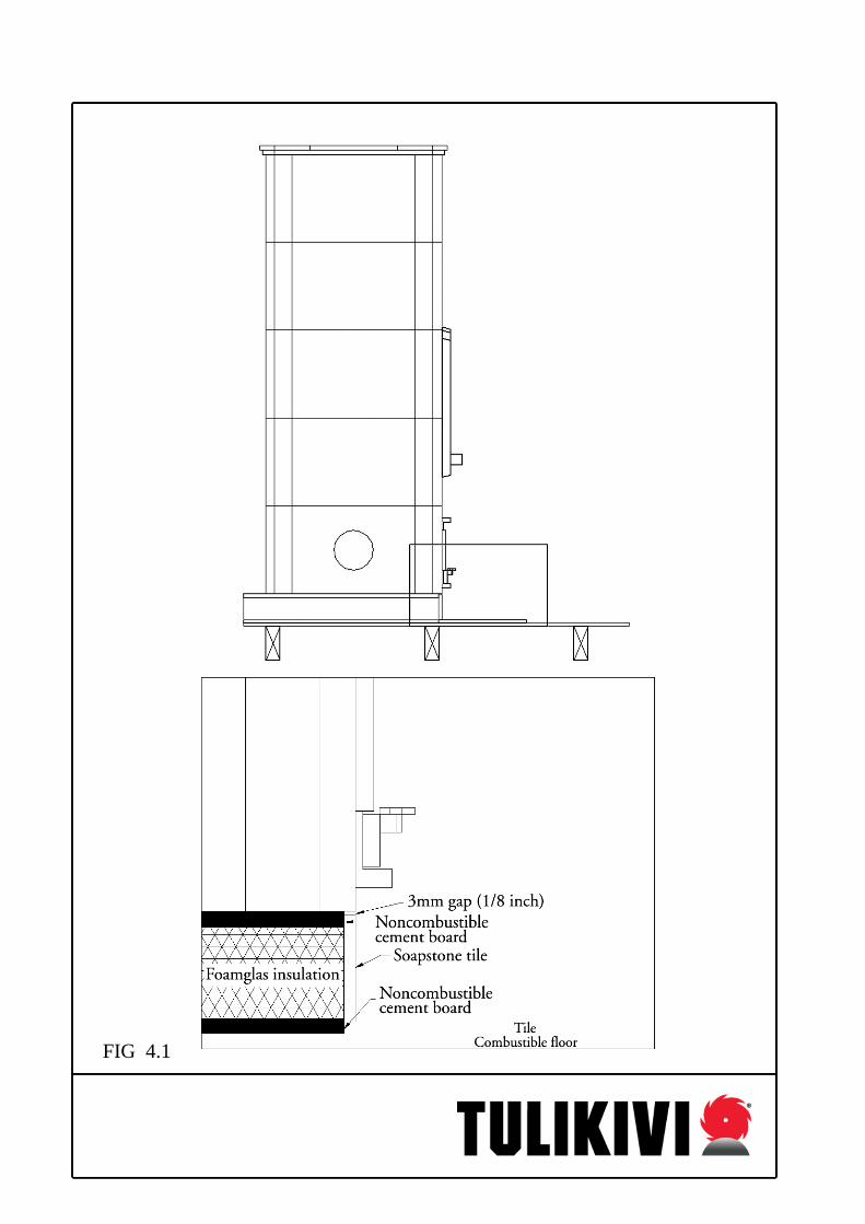
FIG 4.1

FIG 4.2

FIG 4.3 : Foamglas usage between combustible materals and Tulikivi -bench Note! Floor has to be engineered to hold weight of Tulikivi -bench and -heater.
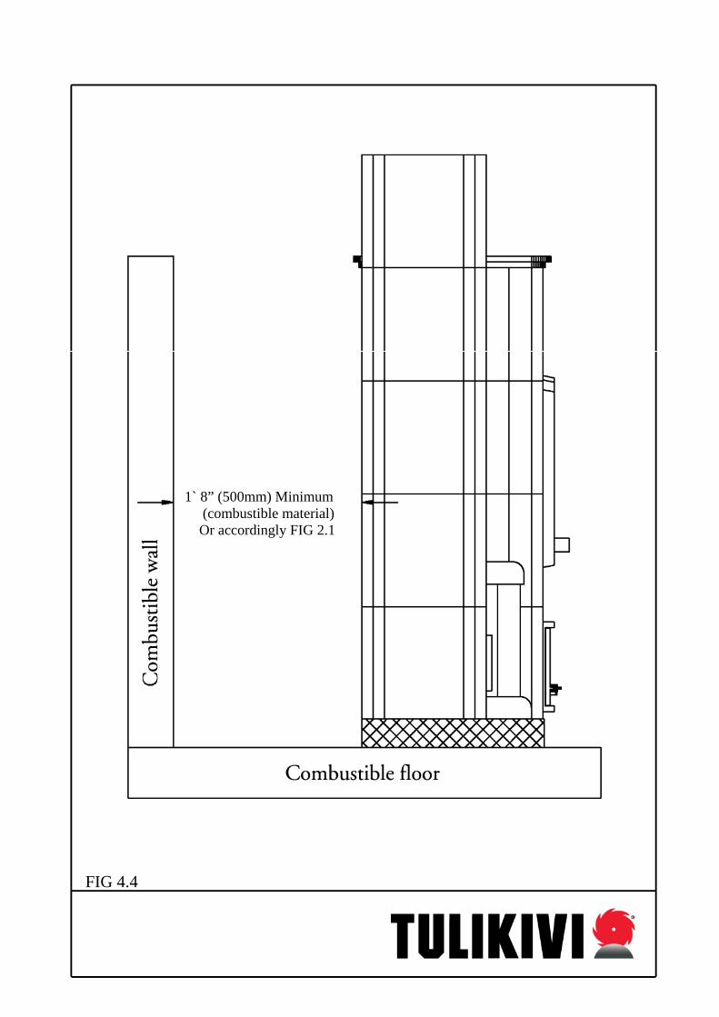
1` 8” (500mm) Minimum (combustible material) Or accordingly FIG 2.1 FIG 4.4
All Tulikivi heaters have following clearances to combustibles: -sides 14” 350mm -back 20” 500mm -top 10” 250mm -front 48” 1200mm -cooktop 20” 500mm Clearances can be reduced to 3” (75mm) by using an on site built heat shield described in following pages. Heat shield consists of two 28 gauge galvanized steel sheets, that are built 1” (25mm) apart from each other and 1” (25mm) apart from the combustible wall. Heat shield can be built by using drywall channels or profiles made out of same material as the heat shield sheets. Sheets and drywall channels are attached to each other by self tapping metal screws #8 x ½” one per every 12”. IMPORTANT: through fasteners to combustible material are not allowed! Heat shield is attached to a wall by using e.g. #6 x 15/8” drywall screws, 1 per every 12”. In case of a drywall, make sure that attaching screws hit the wooden or steel studs in the drywall. Heat shield can be covered from the sides with 3/8” (10mm) soapstone tiles, having a 2” x 3” (50mm x 75mm) air gap on the bottom to secure the air flow. See Fig 4.6. Tiles may not form a bridge from the heater to the combustible wall, 1/8” (3mm) gaps are left between the heater and the tile, and between the tile and the combustible wall. Flat area or the heater has to be covered by the heat shield. If the heater has roundings on the corners, the heat shield (and tiling) has to cover the flat area completely See Fig. 4.5.

FIG 4.5

FIG 4.6
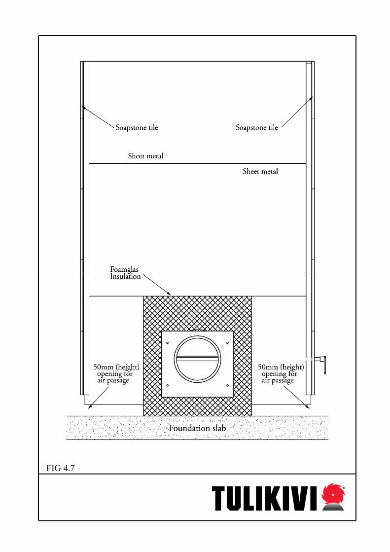
FIG 4.7

FIG 4.8

FIG 4.9

FIG 4.10

FIG 4.11

FIG 4.12

FIG 4.13

DAMPER ASSEMBLY To make Tulikivi –installation easier and trouble-free, there is available stainless steel connection-damper assembly, three standard sizes nominal ∅ 6” (150 mm), ∅ 7” (175 mm)
and ∅ 8” (200 mm). FIG 4.14 : Damper assembly

FIG 4.15 :Top connection

5. UL/ULC Labels and Listing Requirements Tulikivi heaters are safety-tested and listed to be installed according to the guidelines in this manual. However, nothing in this manual should be construed to contradict either the local code or the UL/ULC listing of assosiated materials and installation components. Check with the local authority having jurisdiction before proceeding with any installation to be sure all pertinent rules are followed. Once installed, the UL/ULC labeling should be found both on one primary door and attached to the soapstone below the ash pan. The serial number for each stove must be registered by your dealer and included with you warranty registration form to maintain the listing requirement for each and every Tulikivi.

FIG 5.1
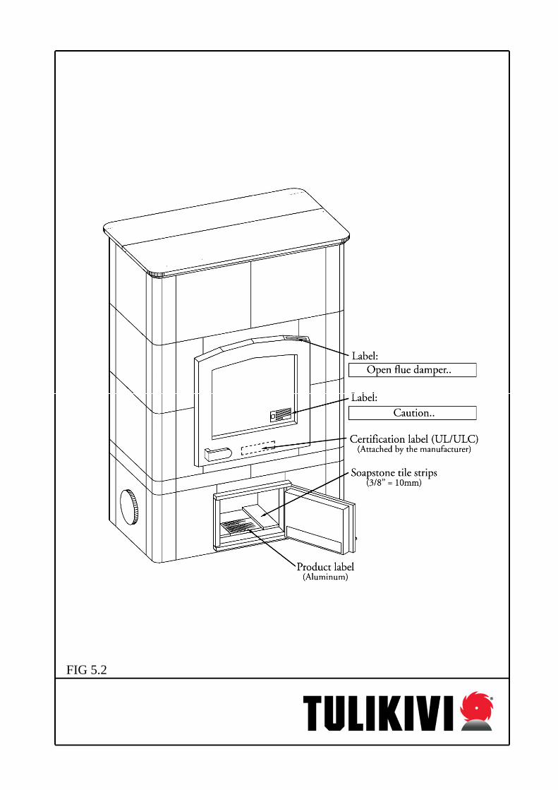
FIG 5.2

FIG 5.3 Certification label will be attached by the manufacturer, 3 others will be placed on site by the installer

FIG 6.1
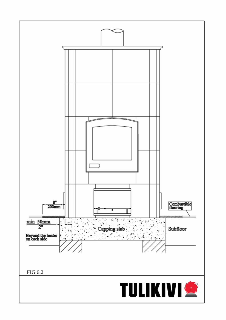
FIG 6.2

TULIKIVI ELECTRIC HEATING These elements are to be installed in accordance with local codes, in the absence of any follow the current ANSI/NFPA-70 – National Electrical Code in the USA and the CSA-C22.1 – Canadian Electrical Code in Canada. Technical data
- Power supply 240 V / 60 Hz - Heater element output a' 500 W - Non -functional section at ends 4-3/4" ( 120 mm ) - Thermal output 6,5 W/In2 ( 1,12 W/cm2) - Tube material AISI 309 (corrosion resistant)
- 2 kW ( 4 x 500 W ) heating elements. -3 kW ( 6 x 500 W ) heating elements.
Components supplied - 2 kW ( 4 x 500 W ) heating elements.
- 3 kW ( 6 x 500 W ) heating elements.
The necessary cables and lead sets pre-assembled, connectors in place. Connection cable and internal lead sets have silicone sheaths and withstand temperatures of up to 392°F (+200°C).
Installation and maintenance The installation of the electric heater components is the last stage in heater assembly. It must be carried out only by an authorized person ( i.e. a specially trained authorized Tulikivi mason or qualified electrician ). External connection may only be carried out by an qualified electrician, and the internal connection either by a specially trained Tulikivi mason or an qualified electrician. Service must be performed by qualified persons. Power must be switched off during soot cleaning.

1. Positioning the heater elements The heater elements are installed in the heat exchange channel, hanging from the fire tube capstones by their attachment brackets. To make space for the heater element, a set of 3/8" (10 mm) holes has to be drilled, such that the distance between the outer edges of the furthest holes is about 3-1/8" (85 mm). The stone between the holes is then chipped away with a 3/8" (10 mm) bit (Fig. 7.1). When positioning a heater clement, make sure that the element lies near to the heat exchange channel wall and does not impair soot removal. Attach the heater elements to the fire tube capstones using the 4x30mm screws provided; 1/8" (3,5mm) holes have to be drilled for these screws in the fire tube capstones. 2. Insulating capstones Lay 3x12mm isoglas insulation on top of the capstones. Make small holes in the insulation for the ends of the heater elements. (Fig. 7.2). Note: Do not pack the mineral wool so tightly that its insulating effect is lost. 3. Internal electric installation Heater elements are connected together using only wiring and components provided by Tulikivi. (Fig 7.4) Factory delivered metal plate (“*”) with 7/8” (22mm) hole is installed on the face of the heater according to a following diagram (Fig 7.3) using 4x30mm screws. 4. External electric installation A qualified electrician connects factory furnished high temperature 392°F (200°C) connection cable to the junction box (power supply). Approved rigid metal conduit is installed between a metal plate (“*”) in Tulikivi unit and a locally approved junction box. (Fig. 7.5) 5. Controlling heater elements Electric heating is controlled by a system including a thermostat or timing device. This system must be certified and capable of switching 2 kW. 6. Label Each Tulikivi unit with an electric heaters is provided with following label, placed visibly in the face of the heater, located close to the penetration of the heater by the metal conduit. (Fig. 7.6)

FIG 7.1 FIG 7.2
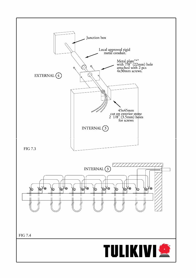
FIG 7.3 FIG 7.4

FIG 7.5 : These elements are to be installed in accordance with local codes, in the absence of any follow the current ANSI/NFPA-70 – National Electrical Code in the USA and
the CSA-C22.1 – Canadian Electrical Code in Canada

FIG 7.6 : Label is placed visibly close to the penetration of the heater by the metal conduit.

A = 270mm A = 270mm B = 360mm B = 360mm
A= 270mm B= 360mm C= 520mm FIG 8.1 : FR-04, FR-05, FR-06

FIG 8.2 FR-04, FR-05, FR-06, Certification UL/ULC label locations

FIG 8.3 Certification UL/ULC label locations

FIG 8.4 Certification label will be attached by the manufacturer, 3 others will be placed on site by the installer