tsp. based aep c) the 2 33 an
TRANSCRIPT
execution of this Agreement, the Generator hereby authorizes the TSP to proceed with the design, procurement and construction of the TIF under this Agreement.
(2) The Parties hereby acknowledge and agree that the September 4, 2008 In-Service Date for Unit 1 is a good faith estimation by the TSP for the In-Service Date for Unit 1 at this time, and that until the TSP has developed and executed certain third party contracts for the installation of the TIF, the In-Service Date for Unit 1 is subject to reasonable adjustment by the TSP. The Parties hereby acknowledge and agree that the July 10,2010 In-Service Date for Unit 2 is based on the timely completion of the enhancements by AEP of its transmission system pursuant to the AEP Agreement (as defined in Exhibit C) and other factors and circumstances that are not presently known or determinable, and accordingly, the In-Service Date for Unit 2 is subject to reasonable adjustment by the TSP. The Parties also hereby acknowledge and agree that the dates and times of this Exhibit 33 assume that the necessary rights-of-way, easements and other real property interests are timely obtained and that a CCN is not required for the construction of the TIF. In the event that the necessary rights- of-way, easements and other real property interests are not timely obtained, or in the event that a CCN is required, the dates and times of this Exhibit B, including the In-Service Date for one or both Units, shall be extended by an appropriate period of time to reflect the additional time required to obtain the rights-of-way, easements or other real property interest or a CCN, as applicable, as determined by the TSP. The Parties further acknowledge and agree that the In-Service Date for each Unit is dependent upon ERCOT’s approval of scheduled activities, including ERCOT granting clearances to install equipment. None of the foregoing shall be construed as relieving the TSP of its obligations under Section 4.1(A) of this Agreement.
EXECUTION VERSION 41
Exhibit ‘T” Interconnection Details
Name: Sherbino Mesa I Wind Farm LLC
Point of Interconnection location:
The point of interconnection is located in Pecos County, Texas, approximately 27 miles east of Ft. Stockton on the south side of M 10 near Mile Post a 8 7 of M 10. Specifically at the point where the jumpers from the Generator transmission line contact TSP switch AS138-73 terminals in TSP White Baker Switching Station.
Delivery Voltage: 138 kV
Number and size of Generating Units:
Unit 1 of the Plant has an aggregate nameplate generating capacity of 150 M W and consists of fifty (50) wind turbine generating units, each with a nameplate generating capacity of 3 MW. The Generator is scheduled to connect Unit 1 during September 2008. Unit 2 of the Plant has an aggregate nameplate generating capacity of 150 M W and consists of fifty (50) wind turbine generating units, each with a nameplate generating capacity of 3 MW, unless otherwise approved in writing by the TSP as set forth below. The Generator is scheduled to connect Unit 2 during July 2010 to coincide with the completion of enhancements by AEP Texas North Company (“AEP”) of its transmission system pursuant to the Amended and Restated Agreement for Transmission Engineering, Design, Procurement and Construction Services for Transmission Upgrades to the AEP Texas System, dated January 15, 2008, between AEP and Generator (the “AEP Agreement”).
Type of Generating Unit:
Unit 1 shall consist of 50 Vestas V90 wind turbine generators. Unit 2 shall consist of an additional 50 Vestas V90 wind turbine generators (or with the written consent of the TSP, an alternate wind turbine generator approved in writing by the TSP and AFP). The Generator agrees that any change in type of turbine generator may require additional system improvements to both the TSP and AEP transmission systems and may require a modification to Exhibit C and other provisions of this Agreement. In the event the Generator desires to change the type of wind turbine generators for Unit 2, the Generator shall provide reasonable advance written notice to the TSP and AEP of such proposed change to allow sufficient time for the TSP and AEP to review and determine whether the proposed alternate turbine generators have similar operating characteristics to the Vestas V90 wind turbine generators and what, if any modifications are required by the TSP. The TSP may withhold its consent to any requested change in the
EXECUTION VERSION 42
type of wind turbine generator for Unit 2 until a determination has been made by the TSP regarding what, if any, additional system improvements to the TSP transmission systems are required and any modifications required by the TSP to this Agreement have been mutually agreed to by the Parties. The Parties acknowledge the need to review, discuss, coordinate and consent (“Coordination Activities”) on all aspects of Unit 2 installation with respect to interconnection and integration activities. Such Coordination Activities are intended to ensure that the interconnection and integration of Unit 2 is consistent with and adheres to the same criteria and requirements established for Unit 1.
Metering and Telemetry Requirements:
TSP shall, in accordance with ERCOT Requirements and Good Utility .Practice, install, own, operate, inspect, test, calibrate, and maintain 138 kV metering accuracy potential and current transformers and metering and telemetry equipment (including RTU) located in the TIF. A one-line diagram showing TSP’s ERCOT-polled Settlement meter (“S”) metering location is attached to this Exhibit C as Attachment 1-A. TSP will connect its EPS meters to its RTU via a communications link. Data and electrical parameters to be communicated from the TSP to GIF shall be as identified in the SCADA Table in Attachment 2 to this Exhibit C.
To satisfy the ERCOT Requirements for the provision of metering data by Generator’s “Qualified Scheduling Entity”, Generator shall, in accordance with Good Utility Practice, install and maintain equipment necessary to satisfy the requirements of the Qualified Scheduling Entity at the GIF.
Generator shall, in accordance with ERCOT requirements and Good Utility Practice, install, own, operate, inspect,. test, calibrate, and maintain the equipment and telemetry equipment (including RTU or other equipment reasonably acceptable to TSP) to supply all electrical parameters from the Plant and GIF to TSP as specified in the SCADA Table in Attachment 2 to this Exhibit C.
Generator shall, in accordance with ERCOT Requirements and Good Utility Practice, provide communications facilities that are, or may in the future be, necessary for effective interconnected operation of the Generator’s Plant with the transmission system. Generator will directly make arrangements to provide and will bear the cast of installation and ongoing of such facilities. The communications facilities will include:
Fiber Optic cable between the TIF and the GIF control houses using Fiber Optic Ground Wire OPT-GW, CC-54/472 nominal cable size, 24 single-mode fiber;
Two private line voice circuit in the TIF control house; and
League City Communication Path (See Item 9 below).
EXECUTION VERSION 43

Prior to In- Service Date, acceptance test will be performed by TSP and Generator to insure proper functioning of all metering, telemetry, and communications equipment and to verify the accuracy of data being received by TSP.
Following the Commercial Operation date with respect to each Unit, each Party shall test its metering, telemetry, and communications equipment in accordance with ERCOT Requirements and Good Utility Practice. Each Party shall give the other Party reasonable advance notice of such testing. Each Party shall have the right to observe testing performed by the other Party.
Each Party will promptly advise the other Party if it detects or otherwise learns of any metering, telemetry, or communications equipment or related situation that requires attention and /or correction by the other Party.
Generator Interconnection Facilities: The GIF shall include the following facilities.
Generator Transmission Facilities
The Generator will be responsible for the construction and ownership of an estimated five (5) miles of 138 kV transmission line facilities from the Generator’s Plant 138 kV switchyard to the TSP switching station inclusive of fiber optic cable. The transmission line and fiber optic cable will be maintained by Generator to the designated point of interconnect. The designated point of interconnect for the transmission line will be the line side terminal of air switch AS138-73 located on the TIF dead-end structure in the TSP white Baker Station. The designated point of interconnect for the fiber optic is the fiber optic patch panel designated by the TSP in the TIF control house. OPGW fiber optic cable will be installed by the Generator from the GIF to a termination cabinet located at the base of the TIF dead-end structure. ADSS cable shall be installed by the Generator from the termination cabinet to the patch panel located in the TIF control house. TSP shall install appropriate duct bank, conduit, and/or interduct from the termination cabinet to the TIF control house for use by Generator to install the ADSS cable.
TSP has the right to inspect, with reasonable prior notice to Generator and during normal business hours, Generator’s transmission line facilities and dead end structure to verify that it does meet all clearance requirements prior to the interconnection of the TSP’s facilities to Generator’s facilities. TSP reserves the right to deny interconnect rights if the line does not meet Applicable Legal and Electrical Requirements (as defined below) and to continue denying the interconnect rights until such time that the line does meet Applicable Legal and Electrical Requirements. “Applicable Legal and Electrical Requirements” shall mean, collectively, Good
ExEcunoN VERSlON 44
Utility Practice, the National Electrical Safety Code (as approved by the American National Standards Institute), National Electric Reliability Corporation (“NERC”) Standards, ERCOT Requirements, PUCT Rules and Applicable Laws.
Generator Plant Switchyard Facilities (“Keo”)
The following list of major switchyard equipment has been identified by the Generator for the Plant switchyard. Items marked with an (*) shall be installed in conjunction with the AEP transmission system enhancements to be made by AEP pursuant to the AEP Agreement to provide for the export of a total of 300 MW from the Plant. A one-line diagram showing the Generator Plant Switchyard Facilities for Unit 1 is attached to this Exhibit C as Attachment 1-B.
Initial Equipment required for Unit 1 Output:
EXECUTIoN VERSION
Metering and Telemetry as provided in Item 6 above. (1 ea) Digital Fault Recorder (1 ea) 138 kV, 2000 amp, 40 kA circuit breakers (1 ea) 138 kV, 2000 amperes, gang operated, 3 phase air break
(4 ea per phase) 2000:s amp breaker bushing CT’s for relaying (1 ea per phase) CCVTs for relaying (3 ea per phase) 84 kV surge arresters
switch
(1 ea) auto-transformer 138/34.5 kV Y-Y: 176 MVA @ 65 degrees C rise No-Load Tap Changer: None Impedance: 9% on 106 MVA base. (3 ea per phase) 12005 amp high side bushing CT’s for
(3 ea per phase) 4000:5 amp low side bushing CT’s for
(1 ea per phase) 1200:5 amp CT for neutral relaying
relaying
relaying
(4 ea) 11 MVAR switched capacitor banks
Additional Equipment Required For Unit 2 Output (*):
(1 ea) 138 kV, 2000 amp, 40 kA circuit breakers * (1 ea) 138 kV, 2000 amperes, gang operated, 3 phase air break switch* (4 ea per phase) 2000:5 amp breaker bushing CT‘s for relaying*
(1 ea) auto-transformer 138/34.5 kV Y-Y:* 176 MVA @ 65 degrees C rise No-bad Tap ChangeK None Impedance: 9% on 106 MVA base.
45
54
(3 ea per phase) 1200:5 amp high side bushing CT’s for
(3 ea per phase) 40005 amp low side bushing CT’s for
(1 ea per phase) 12005 amp CT for neutral relaying
relaying
relaying
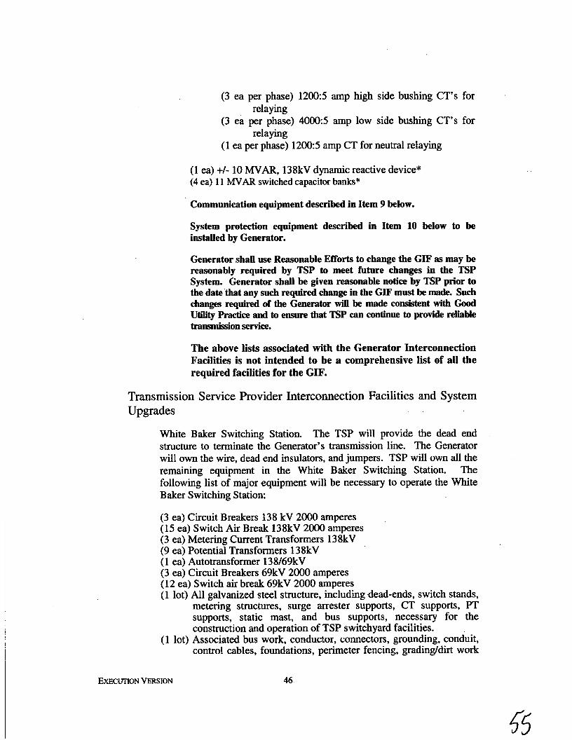
(1 ea) +/- 10 WAR, 138kV dynamic reactive device* (4 ea) 11 WAR switched capacitor banks*
Communication equipment described in Item 9 below.
System protection equipment described in Item 10 below to be installed by Generator.
Generator shall use Reasonable Efforts to change the GIF as may be reasonably required by TSP to meet future changes in the TSP System. Generator shall be given reasonable notice by TSP prior to the date that any such required change in the GIF must be made. Such changes required of the Generator will be made ConsWnt with Good Utility Practice and to ensure that TSP can continue to provide reliable trammaon service. . . The above lists associated with the Generator Interconnection Facilities is not intended to be a comprehensive list of all the required facilities for the GIF.
Transmission Service Provider Interconnection Facilities and System Upgrades
White Baker Switching Station. The TSP will provide the dead end structure to terminate the Generator’s transmission line. The Generator will own the wire, dead end insulators, and jumpers. TSP will own all the remaining equipment in the White Baker Switching Station. The following list of major equipment will be necessary to operate the White Baker Switching Station:
(3 ea) Circuit Breakers 138 kV 2000 amperes (15 ea) Switch Air Break 138kV 2000 amperes (3 ea) Metering Current Transformers 138kV (9 ea) Potential Transformers 138kV (1 ea) Autotransformer 138/69kV (3 ea) Circuit Breakers 69kV 2000 amperes (12 ea) Switch air break 69kV 2000 amperes (1 lot) All galvanized steel structure, including dead-ends, switch stands,
metering structures, surge arrester supports, CT supports, PT supports, static mast, and bus supports, necessary for the construction and operation of TSP switchyard facilities.
( 1 lot) Associated bus work, conductor, connectors, grounding, conduit, control cables, foundations, perimeter fencing, gradingldirt work
EXECUTION VERSION 46
55
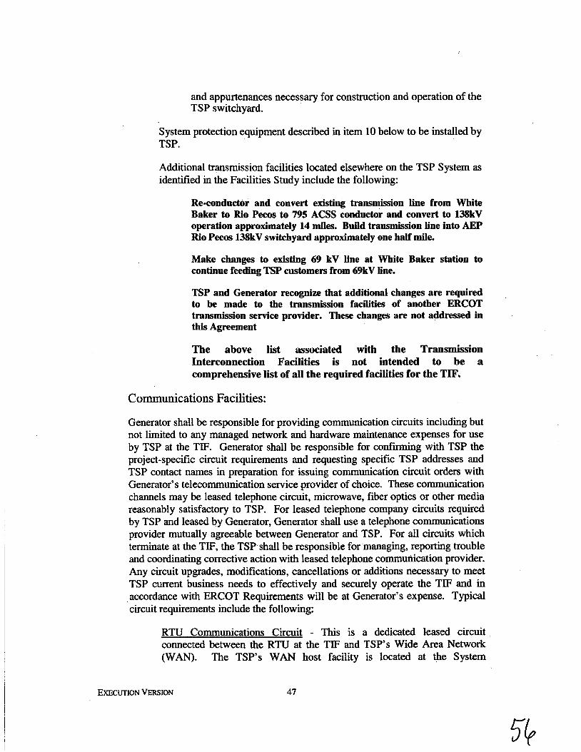
and appurtenances necessary for construction and operation of the TSP switchyard.
System protection equipment described in item 10 below to be installed by TSP.
Additional transmission facilities located elsewhere on the TSP System as identified in the Facilities Study include the following:
Re-conductor and convert existing transmission line from White Baker to Rio Pecos to 795 ACSS conductor and convert to 138kV operation approximately 14 miles. Build transmission line into AEP Rio Pems 138kV switchyard approximately one half mile.
Make changes to existing 69 kV line at White Baker station to continue feeding TSP customers from 69kV line.
TSP and Generator recognize that additional changes are required to be made to the transmission facilities of another ERCOT transmission service provider. These changes are not addressed in this Agreement
,
The above list associated with the Transmission Interconnection Facilities is not intended to be a comprehensive list of all the required facilities for the TIF.
Communications Facilities:
Generator shall be responsible for providing communication circuits including but not limited to any managed network and hardware maintenance expenses for use by TSP at the TIF. Generator shall be responsible for confirming with TSP the project-specific circuit requirements and requesting specific TSP addresses and TSP contact names in preparation for issuing communication circuit orders with Generator’s telecommunication service provider of choice. These communication channels may be leased telephone circuit, microwave, fiber optics or other media reasonably satisfactory to TSP. For leased telephone company circuits required by TSP and leased by Generator, Generator shall use a telephone communications provider mutually agreeable between Generator and TSP. For all circuits which terminate at the TIF, the TSP shall be responsible for managing, reporting trouble and coordinating corrective action with leased telephone communication provider. Any circuit upgrades, modifications, cancellations or additions necessary to meet TSP current business needs to effectively and securely operate the TIF and in accordance with ERCOT Requirements will be at Generator’s expense. Typical circuit requirements include the following:
RTU Communications Circuit - This is a dedicated leased circuit connected between the RTU at the TIF and TSP’s Wide Area Network (WAN). The TSP‘s WAN host facility is located at the System
EXECUTION VERSION 47
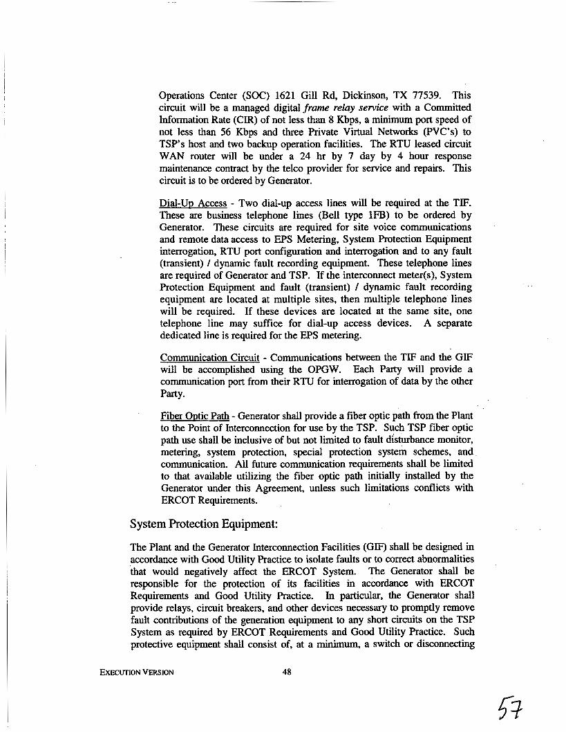
Operations Center (SOC) 1621 Gill Rd, Dickinson, TX 77539. This circuit will be a managed digital frame relay service with a Committed Information Rate (CIR) of not less than 8 Kbps, a minimum port speed of not less than 56 Kbps and three private Virtual Networks (PVC’s) to TSP’s host and two backup operation facilities. The RTU leased circuit WAN router will be under a 24 hr by 7 day by 4 hour response maintenance contract by the telco provider for service and repairs. This circuit is to be ordered by Generator.
Dial-Uu Access - Two dial-up access lines will be required at the TIF. These are business telephone lines (Bell type 1FB) to be ordered by Generator. These circuits are required for site voice communications and remote data access to EPS Metering, System Protection Equipment interrogation, RTU port configuration and interrogation and to any fault (transient) / dynamic fault recording equipment. These telephone lines are required of Generator and TSP. If the interconnect meter(s), System Protection Equipment and fault (transient) / dynamic fault recording equipment are located at multiple sites, then multiple telephone lines will be required. If these devices are located at the same site, one telephone line may suffice for dial-up access devices. A separate dedicated line is required for the EPS metering.
Communication Circuit - Communications between the TIF and the GIF will be accomplished using the OPGW. Each Party will provide a communication port from their RTU for interrogation of data by the other Party.
Fiber &tic Path - Generator shall provide a fiber optic path from the Plant to the Point of Interconnection for use by the TSP. Such TSP fiber optic path use shall be inclusive of but not limited to fault disturbance monitor, metering, system protection, special protection system schemes, and communication. All future communication requirements shall be limited to that available utilizing the fiber optic path initially installed by the Generator under this Agreement, unless such limitations conflicts with ERCOT Requirements.
System Protection Equipment:
The Plant and the Generator Interconnection Facilities (GIF) shall be designed in accordance with Good Utility Practice to isolate faults or to correct abnormalities that would negatively affect the ERCOT System. The Generator shall be responsible for the protection of its facilities in accordance with ERCOT Requirements and Good Utility Practice. In particular, the Generator shall provide relays, circuit breakers, and other devices necessary to promptly remove fault contributions of the generation equipment to any short circuits on the TSP System as required by ERCOT Requirements and Good Utility Practice. Such protective equipment shall consist of, at a minimum, a switch or disconnecting
EXECUTION VERSION 48

device with the appropriate interrupting capability to be located at the Plant switchyard. In addition to faults inside the Plant and GIF, the Generator is responsible, to the extent required by ERCOT Requirements and Good Utility Practice, for protection of such facilities from such conditions as negative sequence currents, over and under frequency events, sudden load rejection, over or under voltage, Generator loss of field, inadvertent energization (reverse power) and un-cleared transmission system faults.
The Plant and the GIF shall have protective relaying that is consistent with relaying criteria described in the ERCOT Requirements and North American Electric Reliability Corporation (“NERC”) standards. If requested by the TSP, Generator shall provide corrections or additions to existing control and equipment required to protect the transmission system, provided such corrections or additions are required by ERCOT Requirements and Good Utility Practice.
The relay designs shall incorporate necessary test switches to enable complete functional testing. The test switches will be placed such that they allow operations of the relay without tripping the breaker failure scheme and causing unnecessary breaker trips and tripping of the generator units.
Prior to modifying any relay protection system design or relay setting involving the connection between the Plant and the TSP System, Generator shall submit the proposed changes to TSP for review and approval. TSP review and approval shall be for the limited purpose of determining whether the proposed changes are compatible with the TSP transmission system so as to not affect the ERCOT system, and shall not be unreasonably withheld or delayed.
In accordance with Good Utility Practice, the TSP shall determine requirements for protection of the Point of Interconnection and the zone of protection around the Point of Interconnection and shall specify and implement protection and control schemes as necessary to meet such requirements. Generator shall have the right to review and comment on such protection requirements and such comments shall not be unreasonably refused when determining such requirements. The TSP and Generator shall work together to coordinate the relay system protection between the GIF and the TSP transmission system so as to not affect the ERCOT system. Relaying may require updating from time to time, and the Parties will be responsible to update, at their costs, the relay enhancements consistent with Good Utility Practice.
TSP WHITE BAKER SWITCHING
TSP 138kV line from TSP White Baker Station (“WB”) to AEP’s Rio Pecos Plant
TSP shall provide line protection for the WB - Rio Pecos line. The line protection shall be provided by using GE-L90 line differential and SEL-421 POT” scheme ring-bus panels compatible with the AEP standard design. This panel will utilize
EXECUTION VERSION 49
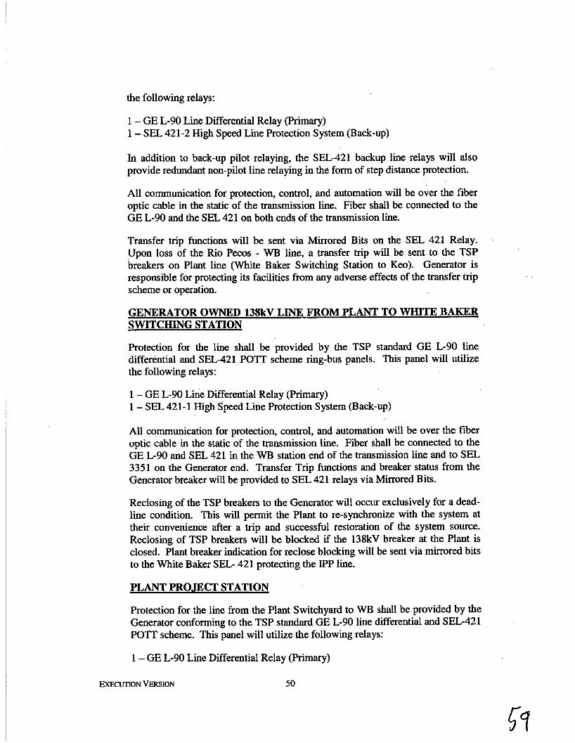
the following relays:
1 - GE L-90 Line Differential Relay (Primary) 1 - SEL 421-2 High Speed Line Protection System (Back-up)
In addition to back-up pilot relaying, the SEL-421 backup line relays will also provide redundant non-pilot line relaying in the form of step distance protection.
All communication for protection, control, and automation will be over the fiber optic cable in the static of the transmission line. Fiber shall be connected to the GE L-90 and the SEL 421 on both ends of the transmission line.
Transfer trip functions will be sent via Mirrored Bits on the SEL 421 Relay. Upon loss of the Rio Pecos - WB line, a transfer trip will be sent to the TSP breakers on Plant line (White Baker Switching Station to Keo). Generator is responsible for protecting its facilities from any adverse effects of the transfer trip scheme or operation.
GENERATOR OWNED 138kV LINE FROM PLANT TO WHITE BAKER SWITCHING STATION
Protection for the line shall be provided by the TSP standard GE L-90 line differential and SEL-421 POTT scheme ring-bus panels. This panel will utilize the following relays:
1 - GE L-90 Line Differential Relay (Primary) 1 - SEL 421-1 High Speed Line Protection System (Back-up)
All communication for protection, control, and automation will be over the fiber optic cable in the static of the transmission line. Fiber shall be connected to the GE L-90 and SEL 421 in the W B station end of the transmission line and to SEL 3351 on the Generator end. Transfer Trip functions and breaker status from the Generator breaker will be provided to SEL 421 relays via Mirrored Bits.
Reclosing of the TSP breakers to the Generator will occur exclusively for a dead- line condition. This will permit the Plant to re-synchronize with the system at their convenience after a trip and successful restoration of the system source. Reclosing of TSP breakers will be blocked if the 138kV breaker at the Plant is closed. Plant breaker indication for reclose blocking will be sent via mirrored bits to the White Baker SEG 421 protecting the IPP line.
PLANT PROJECT STATION
Protection for the line from the Plant Switchyard to WB shall be provided by the Generator conforming to the TSP standard GE L-90 line differential and SEL-421 POTT scheme. This panel will utilize the following relays:
1 - GE L-90 Line Differential Relay (Primary)
-ON VERSION 50

1 - SEL 421-1 High Speed Line Protection System (Back-up) 1 - Breaker Failure Relay
The breaker failure relay must be able to interface with the SEL-421 to send a transfer trip to the WB breakers via Mirrored Bits.
There will be no automatic reclosing on the transmission line from the Generator station side.
The SEL-421 at the station must supply breaker position via Mirrored Bits to the SEL-421 at the W B station protecting the WB - Keo line.
TSP requests review of Generator line protection design to ensure compatibility.
Generator shall install sufficient digital fault recording equipment, in accordance with ERCOT Requirements, to analyze system disturbances of the ERCOT system in the immediate area. This equipment shall monitor the voltages at all major nodes of the system, cunent at major branches, breaker and switch positions and enough of the dc logic in the relay control scheme to analyze a system disturbance. All Fault and dynamic recorders shall be equipped with time synchronizing equipment.
Inputs to Telemetry Equipment:
Point of Interconnection data points and Plant data points required for telemetry will be provided to TSP in accordance with Item 6.
Supplemental Terms and Conditions, if any, Attached:
The Supplemental Terms and Conditions are attached hereto as Exhibit C-12
Special Operating Conditions:
The nature of the upgrades on the TSP System are limited to providing radial service from the GIF Point of Interconnection on TSP’s transmission system to the AEP Rio Pecos switching station. Both the Generator and TSP agree that the Plant output and any back feed to the Plant will be reduced to 0 M W with outages of the TSP transmission line facilities between Rio Pecos switching station and the Point of Interconnection. Such action is consistent with the results of the Facility Study. In the event that system enhancements occur after the date hereof such that the Plant output or any back feed to the Plant is not required to be reduced to 0 MW with outages of the TSP transmission line facilities between Rio Pecos switching station and the Point of Interconnection, then the Parties agree to work cooperatively with each other to develop a mutually acceptable alternative arrangement that is consistent with the then current system capabilities.
EXE€UnON VERSION 51
A transfer trip scheme will be utilized to disconnect the Plant generation for loss of the 138 kV transmission line to the Rio Pecos switching station as set forth in Section 10 above.
Maximum output of the Plant will not exceed 300 M W without prior approval from TSP.
Generator is responsible for supplying reactive power within the range of .95 lead to .95 lag at the Point of Interconnection as requested by ERCOT. Generator will provide four (4) 11 W A R switched capacitor banks in addition to operating the generators at 0.98 PF leading to 0.96 PF lagging for reactive power support for Unit 1. The Generator shall define additional requirements for Unit 2 and shall provide such additional requirements to the TSP for review and approval. Such review and approval shall not be unreasonably withheld by the TSP.
Generator shall maintain low voltage ride through capability for normal system disturbances as characterized by Generator in the data provided to ERCOT for performing the Full Interconnection Study.
Generator acknowledges that transmission capacity beyond TSP’s point of interconnection with AEP’s transmission system will be insufficient to accommodate the full output of the Plant prior to completion of the AEP system enhancements to be completed by AEP pursuant to the AEP Agreement. Accordingly, curtailment of Plant output is expected from time to time with normal system conditions prior to completion of such AEP system enhancements. The Generator acknowledges and agrees that the installation and completion of the AEP system enhancements are the responsibility of AEP, and the TSP has no obligation or liability reiated to the curtailments or the cost, schedule or completion of the AEP system enhancements. The Generator hereby agrees to indemnify, defend and hold the TSP and its Affiliates and its and their respective officers, directors, employees, representatives and agents from and against any and all claims, actions, demands, liabilities, losses, damages, penalties, costs and expenses, including judgments, costs and reasonable attorneys’ fees, incurred by or asserted against the TSP or its Affiliates relating to or arising out of claims by the Generator or any of its Affiliates in connection with any curtailment of or reduction in generation of the Plant as a result of limitations beyond the TSP’s point of interconnection with AEP’s transmission system or as a result of any failure by AEP to install or complete the enhancements to its system.
EXECUTION VERSION 52
. .

The difference between the estimated cost of the TIF under 4.1.A ($ ) and the estimated cost of the TIF’ under 4.1.B ($ ) is:
NIA , if applicable.
53

Exhibit C-12 Supplemental Terms and Conditions
Practices for Parallel Generation
In addition to installation of specified protective devices for disconnection from the power system, Generator must install and maintain equipment to monitor and verify the proper interconnected operation (both transient and steady state) for expected power system disturbances.
If any generating unit at the Plant is an induction machine or if an inverter system is being considered for the Plant, TSP shall be consulted during the planning and design process.
General Operating and Design Requirements
TSP’s nominal transmission voltages are 69 kV, 138 kV, and 345 kV.
Generator shall change its facilities or equipment as may be reasonably required by TSP to meet future changes in the TSP System. Generator shall be given reasonable notice by TSP prior to the date that any such required change in the GIF must be made.
The Parties shall develop and execute operating procedures to facilitate the coordination and energization of the GIF. The parties will reasonably cooperate in properly synchronizing the Plant with the TSP System. Generator shall provide to TSP, for review, the most current specifications for GIF equipment, including control drawings and one-line diagrams. TSP’s review of Generator’s specifications shall not be construed as confirming or endorsing the design or as any warranty of safety, durability or reliability of the facility or equipment.
Generator shall not energize a de-energized TIF circuit, unless under direction of TSP.
If wye delta connected generator step up transformers are utilized, they shall be wye connected to TIF and delta connected to the GIF. Generator’s use of a wye-wye step up transformer is acceptable to TSP.
The Plant shall not cause objectionable interference with the electric service provided to other customers by TSP, nor jeopardize the security of the ERCOT power system. In order to minimize objectionable interference of the Plant, the Plant shall meet the following criteria to the extent required by ERCOT Requirements:
(a) Voltage - The Plant shall not cause excessive voltage excursions. Generator shall operate its Plant in such manner that the voltage levels on the TSP System are in the same range as if the Plant was not connected to the TSP System. Generator shall provide an automatic method of disconnecting its Plant and GIF from the TIF to protect against excessive voltage excursions.
EXECUTION VERSION 54

(b) Flicker - The Plant shall not cause excessive voltage flicker on the TSP System. Flicker is to be measured at the Point of Interconnection and shall not exceed 1.5% or the Borderline of Visibility Curve Voltage Flicker Chart of ANSVIEEE Standard 141-1993, whichever is less.
(c) Frequency - The operating frequency of the Plant shall not deviate from the frequency of the TSP System. Plant under frequency relays shall be set the same as TSP’s under frequency relays, so that the Plant will not separate from the TSP System during under frequency conditions until all of TSP’s under frequency load shedding equipment has operated.
(d) Harmonics, Telephone Interference and Carrier Interference - The Plant shall not introduce excessive distortion of the TSP System waveforms; voltage and current; telephone interference; or carrier interference at the Point of Interconnection. EEE Standard 519 shall be used as a guide.
Fault and Line Clearing - The Plant and GIF shall be disconnected from the TSP System on occurrence of an outage or fault on the TIF serving the Plant radially. Generator is responsible for the electrical stability of its Plant and providing adequate GIF so that critical fault clearing times are met.
(e)
(0 Power Factor - The power factor of the Plant will be +/- 0.95. For synchronous generators, the generator voltage-var schedule, voltage regulator, and transformer ratio settings will be jointly determined by TSP and Generator to ensure proper coordination of voltages and regulator action. In cases where starting or load changes on induction generators will have an adverse impact on the TSP System voltage, TSP is to be consulted on techniques required to bring voltage changes to acceptable levels.
(g) Ride Through Cauabilitv - The Plant shall have “ride-through” capability for significant system voltage disturbances as identified in the Full Interconnection Study and Item 13 above.
It is the sole responsibility of Generator to protect its Plant and GIF from excessive negative sequence currents.
TSP reserves the right to disconnect and isolate the Plant for any of the following:
1. The Plant, upon TSP’ s reasonable determination, causes objectionable, interference with other customer’s service or with the secure operation of the TSP System.
2. The Plant, upon TSP’s reasonable determination, exceeds the operating boundaries outlined above.
EXECUTION VERSION 55

3. Generator’s control and protective equipment causes or contributes to a hazardous condition. TSP reserves the right to verify all protective equipment including relays, circuit breakers, etc. at the Point of Interconnection and GIF. Verification may include the tripping of the tie breaker by the protective relays.
4. Continued parallel operation of the Plant is hazardous to the Plant, GIF, TIF or TSP System or to the general public in TSP’s reasonable opinion.
5. To provide TSP personnel the clearances for dead line or live line maintenance.
TSP will use Reasonable Efforts to notify Generator before disconnection, but notification may not be possible in emergency situations that require immediate action.
When TSP’s source breakers trip and isolate the Plant, Generator shall use Reasonable Efforts to disconnect its generation from the Point of Interconnection prior to automatic reclosure by TSP. Generator is solely responsible for the protection of its Plant from automatic reclosing by TSP. The Parties recognize and agree that only one path has capacity to carry flows from the Plant to the transmission system. Transfer trip schemes described in Item 10 above shall be used to remove the Plant from the TIF.
Generator may not commence parallel operation of the Plant until consent has been given by TSP, which consent shall not be unreasonably withheld or delayed. TSP reserves the right to inspect the GIF and witness testing of any equipment or devices associated with the Point of Interconnection, provided that at any time that the TSP or any of its agents, representatives, contractors or other invitees is on property of Generator or the Plant, TSP shall comply, and shall cause its agents, representatives, contractors and other invitees to comply, with all site safety rules of Generator and its contractors.
Generator shall submit the most current specifications and single-line drawings of the GIF to TSP for review and approval, which approval shall not be unreasonably withheld or delayed. TSP will review, approve and provide comments only on those portions of the drawings that affect the TSP System. Any changes required by TSP shall be made prior to final issue of drawings and TSP shall be provided with final copies of the revised drawings. TSP’s review and approval of Generator’s specification shall not be construed as confiiing or endorsing the design or as any warranty of safety, durability or reliability of the facility or equipment.
Generator shall maintain an operating log at the Plant, which at a minimum will indicate changes in operating status (available or unavailable) of the GIF, maintenance outages, trip indications or other unusual conditions found upon inspection, in each such case to the extent required by ERCOT Requirements. For generators that are “block-loaded” to a specific M W level, changes in this setting shall also be logged. TSP may waive this requirement at its discretion. Reliability information, as required by ERCOT Requirements, will be maintained by Generator.
Upon reasonable request by the TSP, consistent with Good Utility Practice and to the
EXECUTION VERSION 56
extent required by ERCOT Requirements, Generator will be required to back down the Plant at certain times to maintain reliability of the ERCOT power system.
Construction Practices
The following practices are minimum construction standards and as such do not represent a warranty from TSP of the adequacy of Generator’s design. Construction practices to be followed by Generator include, but are not limited to the following:
Work Schedule and Material - A proposed project timetable, including construction milestones shall be prepared. The schedule should list types, quantity and delivery schedule of major materials and equipment, required dead-line clearances, temporary construction, etc.
Supervision - Knowledgeable and experienced construction management personnel shall be used for quality workmanship, use of specified materials, and coordination of work between the Parties.
Contractors - Qualification of contractors shall be based on familiarity and experience in working around energized and similar installations and on known reputation for quality workmanship.
Safety - Generator and TSP personnel, their guests and agents are to be fully aware of the existence and location of the other Party’s transmission, substation and distribution facilities. Generator and TSP personnel shall be knowledgeable of the risks of conducting activities in the vicinity of such facilities and be knowledgeable of the procedures and precautions necessary to minimize such risks. This includes but is not limited to those set for in the OSHA regulations, National Electric Safety Code (NESC, ANSI C2- 1990), National Electrical Code (NEC and Sections 754.001 el. seq. of the Texas Health and Safety Code). When TSP is on or within Generator’s facility, TSP shall follow all of Generator’s safety rules and regulations. When Generator is on or within TSP’s facility, Generator shall follow all of TSP’s safety rules and regulations.
Upon determination of the Point of Interconnection, the design and construction of new substation facilities on the TSP System necessary to connect the Plant shall be done utilizing current TSP construction, installation, and structural practices for new facilities. For proposed facilities on TSP’s side of the Point of Interconnection, TSP will review project plans with Generator before work commences.
Power Consumption through the Point of Interconnection
The TSP is not a Retail Electric Provider or other person that sells electric energy to retail or wholesale customers. The energy and power that the Plant and GIF may from time to time consume from the transmission grid through the Point of Interconnection (“Back- Feed”) will not be supplied by the TSP, and the Generator shall secure these services elsewhere. Generator will be responsible for obtaining any Back-Feed that the Plant and GIF may consume from the transmission grid through the Point of Interconnection. In
EXECUTION VERSlON 57
addition, Generator acknowledges that single phase power and energy for its office buildings will not be provided by the TSP.
Reimbursement of Costs and Expenses
Prior to the development and execution of this Agreement, at the request of Orion, the TSP and Orion entered into a Funding Agreement (the “Funding Agreement”), dated July 19,2007, that enabled the TSP to initiate the purchase of long lead items for the proposed TIF and to perform other work in connection with the TIF prior to the completion of the facilities studies pursuant to the Interconnection Request and the development and execution of this Agreement. The Generator hereby agrees to pay to the TSP an amount equal to the portion of the TNMP Costs and Expenses (as defined in the Funding Agreement) that the TSP reasonably determines would be excluded from the TSP’s transmission cost of service as allowed by the applicable Governmental Authority (the “Excess Cost Reimbursement”). Within one-hundred twenty (120) days after execution of this Agreement, the TSP shall submit an invoice to the Generator setting forth the Excess Cost Reimbursement, which invoice shall include reasonable and appropriate documentation supporting the amounts invoiced. Within ten (10) days after receipt of such invoice, the Generator shall pay to the TSP the amount invoiced. Amounts not paid on or before the due date shall be payable with interest accrued from the due date to the date of payment at the lower of (a) the greater of (i) the rate of one and one-half percent (1.5%) per month or (ii) the prime rate of interest for United States of America financial institutions as reported from time to time by The WuZZ Street Journal (New York Edition), plus three percent (3%), or (b) the maximum rate permitted by Applicable Law.
The Generator acknowledges and agrees that the Interconnection Request is for a 300 MW wind generation project in Pecos County, Texas. As more fully described in Exhibit C, the Generator is expected to interconnect an aggregate nameplate generating capacity of 150 MW consisting of fifty (50) wind turbine generating units, each with a nameplate generating capacity of 3 MW, during September 2008 to coincide with the TSP system improvements and to interconnect an additional aggregate nameplate generating capacity of 150 MW consisting of fifty (50) wind turbine generating units, each with a nameplate generating capacity of 3 MW, during July 2010 to coincide with the completion of the AEP system enhancements. If at any time the PUCT issues an order excluding from TCOS any portion of the TIF costs that the PUCT finds should not be recovered through TCOS for any reason relating to or arising out of Unit 2 not having achieved Commercial Operation, the Generator shall pay to the TSP an amount equal to such portion of the TIF costs that are excluded from TCOS. The TSP shall submit an invoice to the Generator setting forth the amount payable by the Generator pursuant to this paragraph, which invoice shall include a copy of the relevant PUCT order. Within thirty (30) days after receipt of such invoice, the Generator shall pay to the TSP the amount invoiced. Amounts not paid on or before the due date shall be payable with interest accrued from the due date to the date of payment at the lower of (a) the greater of (i) the rate of one and one-half percent (1.5%) per month or (ii) the prime rate of interest for United States of America fiiancial institutions as reported from time to time by The Wall Street Journal (New York Edition), plus three percent (3%), or (b) the maximum rate permitted by Applicable Law.
EXECUTION VERSION 58
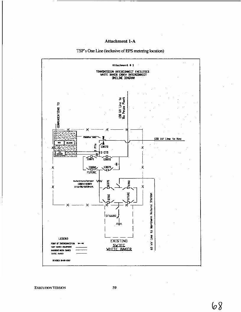
Attachment 1-A
TSP’s One Line (inclusive of EPS metering location)
I x
1
I I ! I i w
13B kV Llne t o Kea
I
I I
EXECUTION VERSION 59
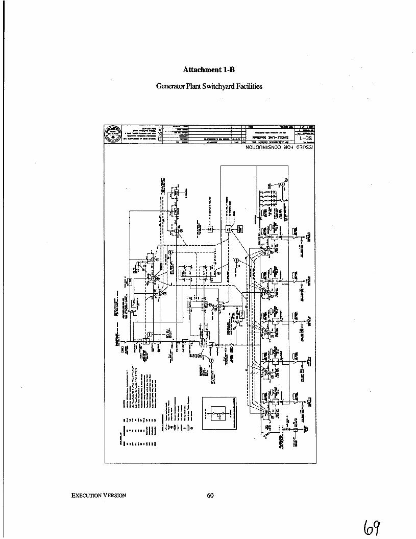
Attachment 1-B
Generator Plant Switchyard Facilities
NOU3ntllSN03 tlOd a3flSSl
t @ )-a- '\\ *
I 4-34
EXECUTION VERSION 60
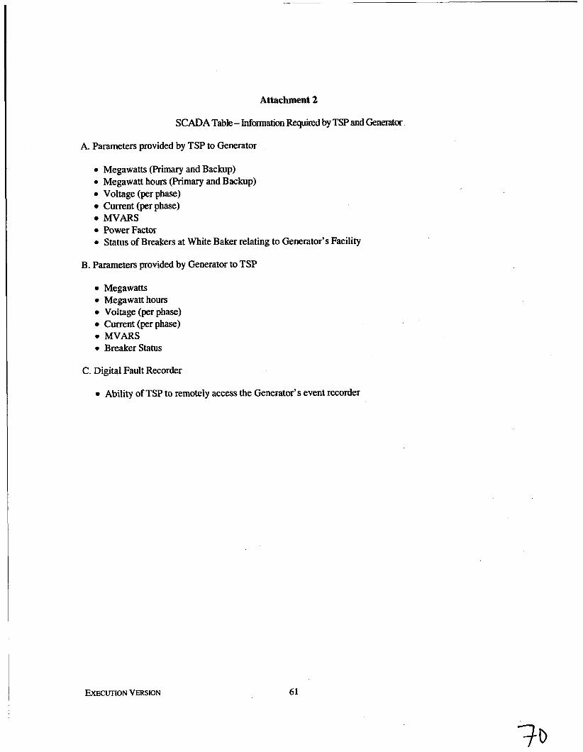
Attachment 2
SCADA Table - Information Requid by TSP and Generator
A. Parameters provided by TSP to Generator
0 Megawatts (Primary and Backup) 0 Megawatt hours (Primary and Backup) 0 Voltage (per phase)
Current (per phase) W A R S
0 Power Factor 0 Status of Breakers at White Baker relating to Generator’s Facility
B. Parameters provided by Generator to TSP
Megawatts 0 Megawatt hours
Voltage (per phase) Current (per phase)
0 MVARS 0 Breakerstatus
C. Digital Fault Recorder
Ability of TSP to remotely access the Generator’s event recorder
EXECUTION VERSION 61
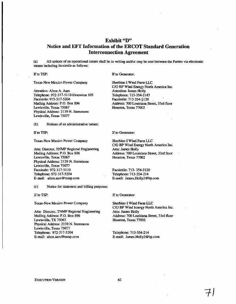
Exhibit “I)” Notice and EFT Information of the ERCOT Standard Generation
Interconnection Agreement
(a) means including facsimile as follows:
All notices of an operational nature shall be in writing andor may be sent between the Parties via electronic
If to TSP
Texas-New Mexico Power Company
Attention: Alton A. Aars Telephone: 972-3 17-5 1 10 Extension 105 Facsimile: 972-3 17-5204 Mailing Address: P.O. Box 8% Lewisville, Texas 75067 Physical Address: 2139 N. Stemmons Lewisville,. Texas 75077
(b) Notices of an administrative nature:
If to TSP
Texas-New Mexico Power Company
Attn: Director, TNMP Regional Engineering Mailing Address: P.O. Box 8% Lewisville, Texas 75067 Physical Address: 2139 N. Stemmons Lewisville, Texas 75077 Facsimile: 972-317-51 10 Telephone: 972-3 17-5204 E-mail: alton.aars @tnmp.com
(c) Notice for statement and billing purposes:
If to TSP
Texas-New Mexico Power Company
Attn: Director, TNMP Regional Engineering Mailing Address: P.O. Box 8% Lewisville, TX 75067 Physical Address: 2 139 N. Stemmons Lewisville, Texas 75077 Telephone: 972-3 17-5204 E-mail: [email protected]
EXECUTION VERSION
If to Generator:
Sherbh I Wind Farm UC C/O BP Wind Energy North America Inc. Attention: James Holly Telephone: 7 13-354-2 143 Facsimile: 713-354-2120 Address: 700 Louisiana Street, 33rd floor Houston, Texas 77002
If to Generator:
Sherbino I Wind Farm LLC C/O BP Wind Energy North America Inc. Attn: James Holly Address: 700 Louisiana Street, 33rd floor Houston, Texas 77002
Facsimile: 713- 354-2120 Telephone: 7 13-354-214 E-mail: James.HoIly29bp.com
If to Generator:
Sherbino I Wind Farm LLC C/O BP Wind Energy North America Inc. Attn: James Holly Address: 700 Louisiana Street, 33rd floor Houston, Texas 77002
Telephone: 7 13-354-2 14 E-mail: [email protected]
62
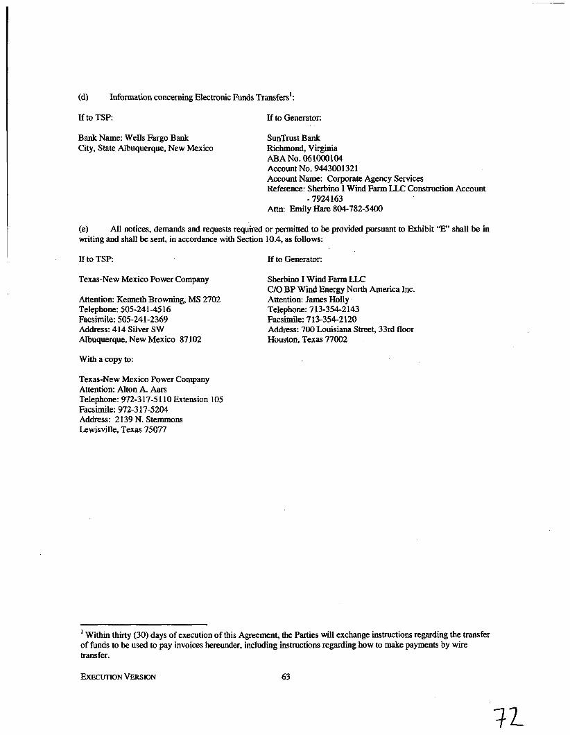
(d) Information concerning Electronic Funds Transfers':
If to TSP: If to Generator:
Bank Name: Wells Fargo Bank City, State Albuquerque, New Mexico
SunTrust Bank Richmond, Virginia ABA No. 061ooO104 Account No. 9443001321 Account Name: Corporate Agency Services Reference: Sherbino I Wind Farm LLC Construction Account
Attn: Emily Hare 804-782-5400 - 7924163
(e) writing and shall be sent, in accordance with Section 10.4, as follows:
All notices, demands and requests required or permitted to be provided pursuant to Exhibit "E" shall be in
If to TSP
Texas-New Mexico Power Company
Attention: Kenneth Browning, MS 2702 Telephone: 505-24 1 -45 16 Facsimile: 505-24 1-2369 Address: 414 Silver SW Albuquerque, New Mexico 87 102
If to Generator:
Sherbino I Wind Farm U C C/O BP Wind Energy North America Inc. Attention: James Holly Telephone: 7 13-354-2143 Facsimile: 7 13-354-2 120 Address: 700 Louisiana Street., 33rd floor Houston, Texas 77002
With a copy to:
Texas-New Mexico Power Company Attention: Alton A. Aars Telephone: 972-317-51 10 Extension 105 Facsimile: 972-3 17-5204 Address: 2139 N. Stemmons Lewisville, Texas 75077
Within thirty (30) days of execution of this Agreement, the Parties will exchange instructions regarding the transfer 1
of funds to be used to pay invoices hereunder, including instructions regarding how to make payments by wire transfer.
EXECUTION VERSION 63

Exhibit “E” Security Arrangement Details
On the date hereof, the Generator has provided Performance Assurance (as defined below) to the TSP in the form of a letter of credit as collateral securing the performance by the Generator of its obligations hereunder. The Generator shall provide and maintain Performance Assurance in an amount not less than the Collateral Amount (as defied below). Further, Generator shall provide written notice to TSP not more than 75 days nor less than 60 days prior to the date of expiration of any letter of credit provided to TSP as Performance Assurance under this Agreement, together with an explanation of how Generator intends to either extend or renew such letter of credit or replace such letter of credit with other Performance Assurance required by this Agreement, and in each case: (a) the extension or renewal of the then current letter of credit or the replacement of such letter of credit with other Performance Assurance shall be effected not less than 45 days prior to the expiration date of the then current letter of credit; and (b) any extended, renewed or replacement letter of credit will not expire prior to the date that is one year from the expiration date of the then current letter of credit. If at any time hereafter, the amount of Performance Assurance held by the TSP is less than the Collateral Amount, then the TSP may request that the Generator provide additional Performance Assuranm to the TSP in an amount equal to such deficiency. Within five Business Days after receipt‘of such a written request, the Generator will provide such requested Performance Assurance to the TSP. Any proceeds from a draw by the TSP under a letter of credit provided as Performance Assurance that are received by the TSP and not applied to reduce the Generator’s obligations under this Agreement shall constitute Performance Assurance provided to the TSP in the form of cash. For purposes of determining the amount of Performance Assurance held by the TSP, the following shall apply: (i) for cash, the amount held shall equal the actual amount of any cash provided as Performance Assurance (whether received from the Generator or as proceeds from a draw under a letter of credit that are not applied to reduce the Generator’s obligations under this Agreement); and (ii) for a letter of credit, the amount held shall equal the undrawn face value of the letter of credit, unless such letter of credit expires within forty-five (45) days or the issuer does not have the required credit rating set forth below, in which case, the amount held shall equal zero (0).
If at any time hereafter, the credit rating of a fmancial institution that is the issuer of a letter of credit provided as Performance Assurance to the TSP hereunder falls below “A2” by Moody’s Investors Service, Inc. or “A” by Standard and Poor’s Corporation, the TSP may request alternate Performance Assurance from the Generator in an amount equal to the Collateral Amount. Within five Business Days after receipt of such a written request, the Generator will provide such requested Performance Assurance to the TSP.
Failure to provide Performance Assurance as required by this Agreement within the time period specified in this Exhibit E shall be deemed a Default under Section 10.6 of this Agreement, notwithstanding any cure period otherwise provided for in Section 10.6.
Notwithstanding any notice provided by the Generator to the TSP regarding the expiration of a letter of credit provided to the TSP as Performance Assurance, or the Generator’s intentions regarding renewal or replacement of such letter of credit, the TSP may draw down any letter of credit provided to it as Performance Assurance in the event that such letter of credit has
64
not been renewed or replaced by some other Performance Assurance at least forty-five (45) days prior to the expiration date of such letter of credit. Any and all amounts drawn by the TSP shall constitute Performance Assurance provided to the TSP in the form of cash.
Performance Assurance shall be provided as collateral securing the performance by the Generator of its obligations under this Agreement. As security for the payment of all amounts due or that may become due from the Generator to the TSP under this Agreement, the Generator hereby grants to the TSP a pledge of and a first priority continuing security interest in and lien on and right of setoff against any cash held by the TSP as Performance Assurance, whether provided to the TSP on the date hereof or thereafter. In addition to any other rights and remedies that may be available to the TSP under this Agreement or otherwise, if the Generator fails to pay any amount hereunder when due, then the TSP may exercise one or more of the following rights and remedies: (i) exercise its rights of setoff against the Performance Assurance; (ii) draw on any letter of credit issued for its benefit; and (iii) exercise any and all rights and remedies available to a secured party under Applicable Law with respect to the Performance Assurance. The TSP shall apply any such setoff against the Performance Assurance and proceeds received from any such draw on a letter of credit to reduce the Generator’s obligations under this Agreement (the Generator remaining liable for any amounts owing to the TSP after such application).
Upon satisfaction of all obligations of the Generator hereunder following the termination of this Agreement or when the TSP receives written notification from Generator that Unit 2 has achieved Commercial Operation, whichever occurs fust, the TSP shall release and return to the Generator, within five Business Days thereafter, any remaining Performance Assurance provided by the Generator under this Agreement. Upon reasonable advance notice, Generator shall have the right to replace any Performance Assurance provided under this Agreement with other Performance Assurance that meets the requirements of this Exhibit E.
As used herein, each of the following terms shall have the meaning set forth below:
’ “Collateral Amount” means an amount equal to Eight Million, Eight Hundred Thousand Dollars ($8,800,000).
“Performance Assurance” means cash or an irrevocable standby letter of credit, in form and substance acceptable to the TSP, from either (a) Fortis Bank S.A.N.V., New York Branch, or (b) a financial institution located within the United States of America, so long as in each such case of the preceding clause (a) and clause (b), the applicable entity has a credit rating of “A2” or better by Moody’s Investors Service, Inc. or “A” or better by Standard and Poor’s Corporation. Any letter of credit may consist of one or more consecutive terms so long as the letter of credit automatically renews from term to term without amendment such that there shall be no interruption of surety provided by the letter of credit.
65