tsi-sp-069 - control equipment for road traffic signals
TRANSCRIPT

ROADS AND MARITIME SERVICES
TRAFFIC SYSTEMS
SPECIFICATION NO. TSI-SP-069
CONTROL EQUIPMENT FOR ROAD TRAFFIC SIGNALS
Issue: 1.0 Dated: 06/09/2018

Specification: TSI-SP-069, Issue 1.0 Page 2 of 294 pages
DISCLAIMER AND CONDITIONS FOR USE OF THIS SPECIFICATION
This Specification has been prepared by Roads and Maritime Services (referred to herein as Roads and Maritime) for use, insofar as it is applicable, in the State of New South Wales for equipment supplied under an Roads and Maritime order or contract, or under an order or a contract from another party that is required in writing by Roads and Maritime to use this Specification. The use of this Roads and Maritime Specification other than by those parties stated above and in the manner stated above is not recommended or authorised by Roads and Maritime. Any such use is entirely the decision of the user alone. Roads and Maritime disclaims all responsibilities and liabilities arising whether directly or indirectly from any such use. Roads and Maritime does not warrant that this Specification is error free, nor does Roads and Maritime warrant the suitability, fitness or otherwise of this Specification for any stated or implied purposes expressed or implied in this Specification or other documents. By using this Specification, the user agrees to indemnify Roads and Maritime against the full amount of all expenses, losses, damages and costs (on a full indemnity basis and whether or not incurred by or awarded against Roads and Maritime) which may be suffered by any person or Roads and Maritime in connection with or arising out of the use of this Specification in any manner. Roads and Maritime is not under any duty to inform you of any errors in or changes to this Specification.
CONTROL EQUIPMENT FOR ROAD TRAFFIC SIGNALS (Copyright RMS 2018)

Specification: TSI-SP-069, Issue 1.0 Page 3 of 294 pages
DECLARATION
This document is a version of Specification TSC/4 for Control Equipment for Road Traffic Signals which only incorporates the original document and amendments 1, 2, 3, 4 and 5.
This document does not address spelling, grammatical or technical inaccuracies; these issues will be addressed in future work.
RECORD OF AMENDMENTS
Issue Summary Date Approved by
0 Original specification TSC/4 titled “Control Equipment for Road Traffic Signals”
17Dec1999 J Bliss
0.1 Incorporating Amendments: 1 (23Aug2004) and 2 (24Dec2009)
15Jun2016
0.2 Incorporating Amendments: 3 (22Jan2016) (deleted text stricken through, new text shown in RED)and 4 (10May2016) (deleted text stricken through, new text shown in BLUE)
24 Jun 2016
0.3 Incorporating Amendments: 5 (17 Oct 2017) (deleted test stricken through, new text shown in GREEN)
04 Jan 2018
0.4 Incorporating minor corrections 14 Jun 2018
1.0 Incorporates a change to the initial Declaration Version for Release
06 Sep 2018 S.Kindleysides
CONTROL EQUIPMENT FOR ROAD TRAFFIC SIGNALS (Copyright RMS 2018)
Specification: TSI-SP-069, Issue 1.0 Page 4 of 294 pages
FOREWORD
The present Specification (TSC/4) includes many new features and enhancements included in traffic signal controllers since the introduction of the previous Specification (TSC/3). Many of these enhancements have resulted from the innovation of the controller manufacturers, and others from Road Authorities in relation to the SCATS system.
The present Specification also includes the knowledge of a number of Road Authorities gained from extensive experience with a large installed base of traffic signal controllers.
The Specification introduces a new concept of compatibility between the controller electronics (or Logic Module) and the wired housing, such that there is interchangeability between equipment of different manufacture.
The Specification aims to tightly specify the requirements for interchangeability, and to specify functional requirements. Where field experience has shown an adverse history for certain materials or methods, the Specification specifically excludes such materials or methods. Other than these areas, the Specification is open to innovation to achieve comparable or better performance.
CONTROL EQUIPMENT FOR ROAD TRAFFIC SIGNALS (Copyright RMS 2018)

Specification: TSI-SP-069, Issue 1.0 Page 5 of 294 pages
C O N T E N T S
1 SCOPE ............................................................................................................................................... 16
1.1 GENERAL................................................................................................................................... 16 1.2 ALTERNATIVE OFFERS................................................................................................................ 16 1.3 NOTES ...................................................................................................................................... 16
2 DEFINITIONS .................................................................................................................................... 17
3 APPLICABLE DOCUMENTS ............................................................................................................ 19
3.1 AUSTRALIAN STANDARD SPECIFICATIONS .................................................................................... 19 3.2 RTA SPECIFICATIONS AND DOCUMENTS ..................................................................................... 20 3.3 OTHER STANDARD SPECIFICATIONS ............................................................................................ 21 3.4 COMPLIANCE WITH SPECIFICATIONS ............................................................................................ 21 3.5 PRECEDENCE OF SPECIFICATIONS .............................................................................................. 22 3.6 EXCEPTIONS TO SPECIFICATION ................................................................................................. 22
4 DRAWING ISSUES ........................................................................................................................... 23
5 TYPE APPROVAL ............................................................................................................................. 24
5.1 GENERAL................................................................................................................................... 24 5.2 PROCEDURE .............................................................................................................................. 24 5.3 TYPE TESTS .............................................................................................................................. 25
5.3.1 Documentation ............................................................................................................ 25 5.3.2 Initial Scrutiny .............................................................................................................. 26 5.3.3 Testing by the Supplier ................................................................................................ 28 5.3.4 Final Scrutiny ............................................................................................................... 31
5.4 FIELD EVALUATION ..................................................................................................................... 31 5.5 ISSUE OF TYPE APPROVAL ......................................................................................................... 32 5.6 RETENTION OF EQUIPMENT ........................................................................................................ 32 5.7 REVOCATION OF TYPE APPROVAL ............................................................................................... 32 5.8 FRAUDULENT CLAIMS ................................................................................................................. 33
6 TECHNICAL REQUIREMENTS ........................................................................................................ 34
6.1 GENERAL REQUIREMENTS .......................................................................................................... 34 6.1.1 General ........................................................................................................................ 34 6.1.2 Site-Specific Adaptation of Equipment ........................................................................ 34 6.1.3 Modular Design ........................................................................................................... 35 6.1.4 Design Life .................................................................................................................. 35 6.1.5 Safety and Reliability ................................................................................................... 35 6.1.6 Protective Coating ....................................................................................................... 35
6.2 FUNCTIONAL REQUIREMENTS (TRAFFIC CONTROL) ...................................................................... 35 6.2.1 General ........................................................................................................................ 35 6.2.2 Inputs and Outputs ...................................................................................................... 36 6.2.3 Signal Display Modes .................................................................................................. 37 6.2.4 Phases and Phase Intervals ....................................................................................... 38 6.2.5 Phase Intervals and Auxiliary Phase Interval .............................................................. 38 6.2.6 Approach Timing ......................................................................................................... 41 6.2.7 Phase Demands .......................................................................................................... 41 6.2.8 Pedestrian Movements and Intervals .......................................................................... 42 6.2.9 Pedestrian Demands ................................................................................................... 42
CONTROL EQUIPMENT FOR ROAD TRAFFIC SIGNALS (Copyright RMS 2018)
Specification: TSI-SP-069, Issue 1.0 Page 6 of 294 pages
6.2.10 Vehicle Signal Group Displays .................................................................................... 43 6.2.11 Pedestrian Signal Group Displays .............................................................................. 43 6.2.12 Safety Interlocks .......................................................................................................... 44 6.2.13 Modes of Operation ..................................................................................................... 44 6.2.14 Controller Start up ....................................................................................................... 46 6.2.15 Minimum Resolution for Timesettings ......................................................................... 48 6.2.16 Normal Running Safety Checks .................................................................................. 48 6.2.17 User Interfaces ............................................................................................................ 48
6.3 CONTROL PROGRAM .................................................................................................................. 49 6.3.1 General ........................................................................................................................ 49 6.3.2 Software Implementation............................................................................................. 50 6.3.3 Software Components and Functions ......................................................................... 50 6.3.4 Control Program for Field Use .................................................................................... 56 6.3.5 Software Execution Times........................................................................................... 56 6.3.6 Diagnostic Software .................................................................................................... 56 6.3.7 Software for Testing Configuration Data ..................................................................... 57 6.3.8 Software Maintenance and Upgrades ......................................................................... 58
6.4 COMPUTER SYSTEM ................................................................................................................... 58 6.4.1 General ........................................................................................................................ 58 6.4.2 Central Processing Unit ............................................................................................... 59 6.4.3 Alternatives For CPU System...................................................................................... 61 6.4.4 RAM ............................................................................................................................. 61 6.4.5 Non Volatile Program Memory .................................................................................... 61 6.4.6 Configuration and System Memory ............................................................................. 63 6.4.7 Interrupt Controller ...................................................................................................... 65 6.4.8 CPU Clock and System Clock ..................................................................................... 65 6.4.9 Hardware Watchdog Timer ......................................................................................... 66 6.4.10 Hardware Start up Timer ............................................................................................. 67 6.4.11 Master Relay Control ................................................................................................... 68 6.4.12 Mains Frequency Clock ............................................................................................... 69 6.4.13 Real Time Clock .......................................................................................................... 70 6.4.14 Mains-Fail Detection .................................................................................................... 70 6.4.15 Standby Power Source ................................................................................................ 71 6.4.16 Memory Map ............................................................................................................... 71 6.4.17 System Architecture .................................................................................................... 71 6.4.18 Workstation ................................................................................................................. 72 6.4.19 Subsystem for Web-based User Interface .................................................................. 73
6.5 INTERFACING, INPUTS AND OUTPUTS .......................................................................................... 73 6.5.1 General Requirements for Protection .......................................................................... 73 6.5.2 General Requirements for Design ............................................................................... 75 6.5.3 Signal Group Outputs .................................................................................................. 79 6.5.4 Pedestrian Wait Indicators .......................................................................................... 84 6.5.5 Detector and Pushbutton Inputs .................................................................................. 85 6.5.6 Facility Switch Inputs ................................................................................................... 89 6.5.7 Master Relay ............................................................................................................... 89 6.5.8 Auxiliary Relay ............................................................................................................. 91 6.5.9 Flasher Unit Interface .................................................................................................. 92 6.5.10 Light Sensor ................................................................................................................ 94 6.5.11 Gas Sensor ................................................................................................................. 94 6.5.12 Daily Event Output ...................................................................................................... 95 6.5.13 Special Facility Control ................................................................................................ 96 6.5.14 VP and Sister Link Control .......................................................................................... 98
CONTROL EQUIPMENT FOR ROAD TRAFFIC SIGNALS (Copyright RMS 2018)

Specification: TSI-SP-069, Issue 1.0 Page 7 of 294 pages
6.5.15 Lamp Monitor Relay (LAMR) ..................................................................................... 101 6.5.16 Detector Loop Inputs ................................................................................................. 101 6.5.17 Mains Frequency Clock Input .................................................................................... 102 6.5.18 Front Panel Switches and Indicators ......................................................................... 103 6.5.19 Site Identification Encoder......................................................................................... 105 6.5.20 No Longer Used Control Panel (Reserved for Future Use) ...................................... 110 6.5.21 Electronic Facility Switch ........................................................................................... 110 6.5.22 Vehicle Detection System ......................................................................................... 111 6.5.23 SCATS Modem ......................................................................................................... 112 6.5.24 SCATS Portable Terminal (TTY) Serial Port ............................................................. 115 6.5.25 Hand Held Terminal (HHT) Serial Port ...................................................................... 116 6.5.26 Intelligent Transportation Systems Serial Ports ........................................................ 117 6.5.27 Ethernet Port for SCATS Communications (XNS) .................................................... 119 6.5.28 Ethernet Port for Web-based User Interface (XNW) ................................................. 120 6.5.29 USB Port (XUP) ......................................................................................................... 120 6.5.30 Dimming by Control Signal – Signalling and Monitor Interface ................................. 120
6.6 REGULATION AND DIMMING OF LAMP SUPPLY VOLTAGE ............................................................. 121 6.6.1 Common Requirements for Regulation and Dimming .............................................. 122 6.6.2 Regulation of Lamp Supply Voltage .......................................................................... 122 6.6.3 Dimming of Signal Displays....................................................................................... 123
6.7 LAMP MONITORING .................................................................................................................. 128 6.7.1 General ...................................................................................................................... 128 6.7.2 Measurements ........................................................................................................... 129 6.7.3 Learning Connected Loads ....................................................................................... 131 6.7.4 Detecting and Reporting Lamp Faults ....................................................................... 133 6.7.5 Clearing of Lamp Faults ............................................................................................ 136
6.8 CONFLICT MONITOR ................................................................................................................. 137 6.8.1 General Requirements .............................................................................................. 137 6.8.2 Conflict Data .............................................................................................................. 138 6.8.3 Signal Display Measurements ................................................................................... 140 6.8.4 Primary Conflict Monitor ............................................................................................ 141 6.8.5 Secondary Conflict Monitor ....................................................................................... 144 6.8.6 Design Requirements for the Conflict Monitors......................................................... 146 6.8.7 Prevention of Confusing Displays ............................................................................. 148
6.9 PCMCIA CARDBUS PERSONALITY MODULE AND INTERFACE ..................................................... 148 6.9.1 General Personality Module ...................................................................................... 149 6.9.2 PCMCIA CardBus Slot Design Operation Support and Connection for Personality Module 150 6.9.3 Configuration Data Storage of Configuration Data and Supplementary Data .......... 151
6.10 POWER SUPPLY ....................................................................................................................... 152 6.10.1 Direct Current Power Supply ..................................................................................... 152 6.10.2 Alternating Current Power Supply ............................................................................. 153 6.10.3 Supply Rail Failure Detection .................................................................................... 154 6.10.4 Mechanical Requirements ......................................................................................... 154 6.10.5 Logic Module Power Consumption ........................................................................... 155
6.11 LOGIC MODULE MECHANICAL ARRANGEMENT ........................................................................... 155 6.11.1 General ...................................................................................................................... 155 6.11.2 Logic Module Layout ................................................................................................. 156 6.11.3 Logic Module Dimensions ......................................................................................... 157 6.11.4 Logic Module Weight ................................................................................................. 157 6.11.5 Logic Module Positioning Devices ............................................................................ 157 6.11.6 Retention of Circuit Cards ......................................................................................... 157
CONTROL EQUIPMENT FOR ROAD TRAFFIC SIGNALS (Copyright RMS 2018)

Specification: TSI-SP-069, Issue 1.0 Page 8 of 294 pages
7 WIRED HOUSING ........................................................................................................................... 158
7.1 GENERAL................................................................................................................................. 158 7.2 HOUSING TYPES ...................................................................................................................... 158
7.2.1 General ...................................................................................................................... 158 7.2.2 Ground-Mounted Housing ......................................................................................... 158 7.2.3 Post-Mounted Housing .............................................................................................. 159
7.3 HOUSING CONSTRUCTION ........................................................................................................ 160 7.3.1 General ...................................................................................................................... 160 7.3.2 Material ...................................................................................................................... 161 7.3.3 Mounting .................................................................................................................... 161 7.3.4 Cable Access and Telecommunications Conduit Access ......................................... 162 7.3.5 Door ........................................................................................................................... 163 7.3.6 Door Hinges .............................................................................................................. 163 7.3.7 Door Locks ................................................................................................................ 164 7.3.8 Door Retainer ............................................................................................................ 164 7.3.9 Weather Sealing ........................................................................................................ 164 7.3.10 Ventilation .................................................................................................................. 165 7.3.11 Plan Pocket ............................................................................................................... 165 7.3.12 No Longer Used ........................................................................................................ 166 7.3.13 Holder for Hand Held Terminal ................................................................................. 166 7.3.14 Equipment Shelf ........................................................................................................ 166 7.3.15 Finish and Protection ................................................................................................. 166 7.3.16 Controller Nameplate ................................................................................................ 167 7.3.17 Resistance to Vandalism ........................................................................................... 167
7.4 CABLE CLAMPING BARS ........................................................................................................... 168 7.4.1 General ...................................................................................................................... 168 7.4.2 Position ...................................................................................................................... 168 7.4.3 Clamping Action and Capacity .................................................................................. 168
7.5 SWITCHBOARD ......................................................................................................................... 169 7.5.1 General ...................................................................................................................... 169 7.5.2 Mounting Position ...................................................................................................... 169 7.5.3 Main Switch and Fault Current Limiter ...................................................................... 169 7.5.4 Lamps Circuit Breaker ............................................................................................... 170 7.5.5 Flash Circuit Breaker ................................................................................................. 170 7.5.6 Logic Circuit Breaker ................................................................................................. 170 7.5.7 Detector Circuit Breaker ............................................................................................ 170 7.5.8 Auxiliary Circuit Breaker and CCTV Circuit Breaker ................................................. 170 7.5.9 Active Bus Bar ........................................................................................................... 170 7.5.10 Neutral Links ............................................................................................................. 171 7.5.11 Earth Link .................................................................................................................. 171 7.5.12 GPO with Integral Residual Current Device .............................................................. 171 7.5.13 Surge Diverter ........................................................................................................... 172 7.5.14 EMI Filter ................................................................................................................... 173 7.5.15 Spare Panel Space for Auxiliary Switch .................................................................... 173 7.5.16 Switchboard Marking ................................................................................................. 174 7.5.17 Order of Switches on the Switchboard ...................................................................... 175 7.5.18 Spare Space for Additional Circuit Breaker............................................................... 175
7.6 FIELD TERMINAL BLOCKS ......................................................................................................... 175 7.6.1 Terminal Types .......................................................................................................... 175 7.6.2 Signal Circuits ........................................................................................................... 176 7.6.3 Lamp Active and Neutral ........................................................................................... 177
CONTROL EQUIPMENT FOR ROAD TRAFFIC SIGNALS (Copyright RMS 2018)

Specification: TSI-SP-069, Issue 1.0 Page 9 of 294 pages
7.6.4 Detector Active and Neutral ...................................................................................... 177 7.6.5 External Detector Inputs and Detector Common ...................................................... 178 7.6.6 Minor Linking ............................................................................................................. 178 7.6.7 Loop Terminations ..................................................................................................... 178
7.7 FACILITY SWITCH ..................................................................................................................... 179 7.7.1 Standard Key ............................................................................................................. 179 7.7.2 Switch Positions and Function .................................................................................. 179 7.7.3 Type and Rating ........................................................................................................ 180 7.7.4 Mounting .................................................................................................................... 180 7.7.5 Weatherproofing ........................................................................................................ 181 7.7.6 Marking ...................................................................................................................... 181 7.7.7 Resistance to Vandalism ........................................................................................... 181 7.7.8 Connection to the Site Identification Card (Connector ZSW) .................................... 181
7.8 MASTER RELAY AND AUXILIARY RELAY ..................................................................................... 182 7.8.1 Function ..................................................................................................................... 182 7.8.2 Type and Rating ........................................................................................................ 182 7.8.3 Mounting, Visibility and Accessibility ......................................................................... 182 7.8.4 Connection to the Site Identification Card (Connector ZMR) .................................... 183
7.9 FLASH CHANGE-OVER RELAYS AND FLASH CIRCUIT PROTECTION .............................................. 183 7.9.1 Function ..................................................................................................................... 183 7.9.2 Provision of Flash Change over Relays and Flash Circuit Protection ...................... 184 7.9.3 Flash Change over Relay Type and Ratings ............................................................ 185 7.9.4 Mounting, Visibility and Accessibility ......................................................................... 185 7.9.5 Selection of Signal Groups for Flashing Yellow ........................................................ 185
7.10 LAMP MONITOR RELAY ............................................................................................................. 186 7.10.1 Function ..................................................................................................................... 186 7.10.2 Type and Rating ........................................................................................................ 186 7.10.3 Mounting, Visibility and Accessibility ......................................................................... 186
7.11 MISCELLANEOUS RELAYS AND CONTACTORS ............................................................................ 187 7.11.1 Function ..................................................................................................................... 187 7.11.2 Type and Rating ........................................................................................................ 187 7.11.3 Mounting, Visibility and Accessibility ......................................................................... 187
7.12 FLASHER UNIT ......................................................................................................................... 187 7.12.1 Function and Connections......................................................................................... 187 7.12.2 Mains Active Supply to the Flasher Unit ................................................................... 188 7.12.3 Flasher Unit Flashing Active Outputs ........................................................................ 189 7.12.4 Prevention of Residual Direct Current to the Load ................................................... 189 7.12.5 Lamp Active Sensing Input........................................................................................ 190 7.12.6 Disable Flash Inputs .................................................................................................. 190 7.12.7 Flasher Unit Mains Supply Operating Voltage Range .............................................. 191 7.12.8 Flash Change-over Relay Drive Output .................................................................... 191 7.12.9 Flash Change-over Relay Status Output .................................................................. 191 7.12.10 Flasher Unit Control Logic ......................................................................................... 192 7.12.11 Mounting, Visibility and Accessibility ......................................................................... 193 7.12.12 ELV Connector (XFC) ............................................................................................... 193 7.12.13 LV Connector (XFP) .................................................................................................. 193 7.12.14 Earthing ..................................................................................................................... 194 7.12.15 Marking ...................................................................................................................... 194 7.12.16 Protective Coating ..................................................................................................... 194
7.13 SITE IDENTIFICATION ENCODER UNIT ........................................................................................ 194 7.13.1 Standard Drawings .................................................................................................... 194 7.13.2 Function ..................................................................................................................... 194
CONTROL EQUIPMENT FOR ROAD TRAFFIC SIGNALS (Copyright RMS 2018)

Specification: TSI-SP-069, Issue 1.0 Page 10 of 294 pages
7.13.3 Site Identification Encoder......................................................................................... 195 7.13.4 Master Relay and Auxiliary Relay Connections (ZMR) ............................................. 196 7.13.5 Facility Switch Connections (ZSW) ........................................................................... 196 7.13.6 Flasher Unit Connections (ZFL) ................................................................................ 197 7.13.7 Light Sensor Connections (ZLS) ............................................................................... 198 7.13.8 Gas Sensor Connections (ZGS) ............................................................................... 198 7.13.9 No Longer Used Control Panel Connections (ZPC) ................................................. 198 7.13.10 Housing Door Switch Connections (ZDR) ................................................................. 199 7.13.11 Controller Logic Module Connections (ZID) .............................................................. 199 7.13.12 Housing Electrical Code Encoder Connections (ZHC) ............................................. 199 7.13.13 Lamp Dimming Signal Generator Connections (ZDC) .............................................. 200 7.13.14 Mounting, Visibility and Accessibility ......................................................................... 200
7.14 TELECOMMUNICATIONS LINE ISOLATION TRANSIENT PROTECTION UNIT ...................................... 200 7.14.1 Conformance with ACA ACMA Standards ............................................................... 200 7.14.2 Function and Circuit Description ............................................................................... 201 7.14.3 Mechanical Arrangement .......................................................................................... 202 7.14.4 Provision for Telephone Wall-Socket Connector Cable and Connector for PSTN Modem Connection................................................................................................................ 203 7.14.5 Mounting .................................................................................................................... 203 7.14.6 Weatherproofing ........................................................................................................ 204 7.14.7 Instruction Label ........................................................................................................ 204 7.14.8 Resistance to Vandalism ........................................................................................... 205 7.14.9 Telecommunications Access Conduit ....................................................................... 205
7.15 LIGHT SENSOR ........................................................................................................................ 206 7.15.1 Function ..................................................................................................................... 206 7.15.2 Type ........................................................................................................................... 206 7.15.3 Mounting .................................................................................................................... 206 7.15.4 Weatherproofing ........................................................................................................ 206 7.15.5 Resistance to Vandalism ........................................................................................... 207
7.16 GAS SENSOR ........................................................................................................................... 207 7.16.1 Function ..................................................................................................................... 207 7.16.2 Type ........................................................................................................................... 207 7.16.3 Sensing Threshold .................................................................................................... 207 7.16.4 Gas Sensor Interface Circuit ..................................................................................... 207 7.16.5 Mounting .................................................................................................................... 208 7.16.6 Protective Coating ..................................................................................................... 208
7.17 NO LONGER USED LAMP DIMMING SIGNAL GENERATOR ............................................................ 208 7.17.1 Function ..................................................................................................................... 208 7.17.2 Dimming Control Inputs ............................................................................................. 208 7.17.3 Dimming Control Monitor Output ............................................................................... 209 7.17.4 Lamp Dimming Control Signal .................................................................................. 209 7.17.5 Indicator lights ........................................................................................................... 209 7.17.6 Mounting, Visibility and Accessibility ......................................................................... 209 7.17.7 Connection to the Site Identification Card (Connector ZDC) .................................... 210
7.18 HOUSING DOOR SWITCH .......................................................................................................... 210 7.18.1 Function ..................................................................................................................... 210 7.18.2 Type ........................................................................................................................... 210 7.18.3 Mounting .................................................................................................................... 210
7.19 EXTRA LOW VOLTAGE (ELV) TRANSFORMER ............................................................................ 211 7.19.1 Function ..................................................................................................................... 211 7.19.2 Type, Voltage and Rating .......................................................................................... 211 7.19.3 Fusing and Connections............................................................................................ 211
CONTROL EQUIPMENT FOR ROAD TRAFFIC SIGNALS (Copyright RMS 2018)

Specification: TSI-SP-069, Issue 1.0 Page 11 of 294 pages
7.19.4 Mounting, Visibility and Accessibility ......................................................................... 212 7.19.5 Marking ...................................................................................................................... 212
7.20 EQUIPMENT MOUNTING SPACE ................................................................................................. 212 7.20.1 Shelf Space ............................................................................................................... 212 7.20.2 Blank Panel Space .................................................................................................... 212
7.21 CONNECTORS .......................................................................................................................... 212 7.21.1 Interface Connectors ................................................................................................. 213 7.21.2 Connector Sensing and Encoding ............................................................................. 213 7.21.3 Connector Coding or Keying ..................................................................................... 213 7.21.4 Connector Backshells ................................................................................................ 213 7.21.5 Connector Retention ................................................................................................. 213 7.21.6 Safety Requirements ................................................................................................. 214
7.22 WIRING ................................................................................................................................... 214 7.22.1 Safety Standards ....................................................................................................... 214 7.22.2 Type and Rating ........................................................................................................ 214 7.22.3 Terminations .............................................................................................................. 214 7.22.4 Marking and Colour Coding ...................................................................................... 214 7.22.5 Protection and Mechanical Support .......................................................................... 215 7.22.6 Equipotential Bonding ............................................................................................... 215 7.22.7 Insulation Resistance ................................................................................................ 215
7.23 INFORMATION TO BE PROVIDED IN THE HOUSING ........................................................................ 216 7.23.1 General ...................................................................................................................... 216 7.23.2 Danger Sign .............................................................................................................. 216 7.23.3 Housing Layout Diagram ........................................................................................... 216 7.23.4 Housing Wiring Diagram ........................................................................................... 217 7.23.5 Approval Numbers ..................................................................................................... 217 7.23.6 Housing Serial Number ............................................................................................. 217
7.24 GENERAL REQUIREMENTS ........................................................................................................ 218 7.24.1 Prevention of Corrosion............................................................................................. 218 7.24.2 Prevention of Accidental Contact with Live Circuits .................................................. 218 7.24.3 Use of Non-Flammable Materials .............................................................................. 218
7.25 HOUSING ELECTRICAL CODE ENCODER UNIT ............................................................................ 218 7.25.1 Function ..................................................................................................................... 219 7.25.2 Construction .............................................................................................................. 219 7.25.3 Housing Electrical Code ............................................................................................ 219
7.26 PROVISION FOR EXTERNAL GENERATOR ................................................................................... 219 7.26.1 General ...................................................................................................................... 219 7.26.2 Protected Cable Entry ............................................................................................... 220 7.26.3 Power Connection and Change-over Unit ................................................................. 220 7.26.4 Cable Support and Clamping .................................................................................... 220 7.26.5 Provision for anchoring the external generator ......................................................... 221
8 ENVIRONMENTAL REQUIREMENTS ............................................................................................ 222
8.1 AMBIENT CONDITIONS .............................................................................................................. 222 8.2 ATMOSPHERIC POLLUTANTS ..................................................................................................... 222 8.3 POWER SUPPLY ....................................................................................................................... 222
8.3.1 Operating Voltage ..................................................................................................... 222 8.3.2 Transient Voltages on Mains Supply Voltage ........................................................... 223 8.3.3 Surges on Mains Supply Voltage .............................................................................. 223 8.3.4 Breaks and Brownouts in Mains Supply Voltage ...................................................... 223 8.3.5 Insulation Resistance ................................................................................................ 224
8.4 SHOCK AND VIBRATION ............................................................................................................ 224
CONTROL EQUIPMENT FOR ROAD TRAFFIC SIGNALS (Copyright RMS 2018)

Specification: TSI-SP-069, Issue 1.0 Page 12 of 294 pages
8.4.1 Shock......................................................................................................................... 224 8.4.2 Vibration .................................................................................................................... 224
8.5 IMMUNITY TO SURGES AND ELECTROMAGNETIC RADIATION ........................................................ 225 8.6 ELECTROMAGNETIC EMISSIONS ................................................................................................ 226 8.7 WEATHER RESISTANCE ............................................................................................................ 226 8.8 ACOUSTIC NOISE ..................................................................................................................... 226 8.9 VANDAL RESISTANCE ............................................................................................................... 226 8.10 FIRE HAZARD ........................................................................................................................... 227
9 DOCUMENTATION ......................................................................................................................... 228
9.1 GENERAL................................................................................................................................. 228 9.2 FIELD MANUAL ......................................................................................................................... 229 9.3 TECHNICAL REFERENCE MANUAL ............................................................................................. 229 9.4 USER MANUAL ......................................................................................................................... 231 9.5 CIRCUIT DIAGRAMS .................................................................................................................. 231 9.6 COMPONENT SCHEDULES ......................................................................................................... 231
10 QUALITY ASSURANCE .................................................................................................................. 232
11 FACTORY TESTING ....................................................................................................................... 233
12 PRE-DELIVERY INSPECTION........................................................................................................ 234
13 PACKAGING ................................................................................................................................... 235
13.1 QUALITY ASSURANCE DOCUMENTATION .................................................................................... 235 13.2 HOUSING ................................................................................................................................. 235 13.3 HEAVY EQUIPMENT .................................................................................................................. 235 13.4 REMOVABLE EQUIPMENT .......................................................................................................... 235
14 WARRANTY AND SPARES............................................................................................................ 236
14.1 WARRANTY .............................................................................................................................. 236 14.2 SPARES ................................................................................................................................... 236
15 INFORMATION TO BE SUPPLIED WITH QUOTATION ................................................................ 237
APPENDIX A – LIST OF DRAWINGS .................................................................................................... 239
APPENDIX B – DEFINITIONS AND ABBREVIATIONS ........................................................................ 241
APPENDIX C – INITIALISATION OF RAM ............................................................................................. 245
C.1 – POWER-UP WITHOUT CONFIGURATION MEMORY ........................................................................ 245 C.2 – INCORRECT INTERSECTION NUMBER .......................................................................................... 245 C.3 – CONTROLLER CLOCK AND CALENDAR ........................................................................................ 245 C.4 – CONTROLLER FAULT/ERROR LOG .............................................................................................. 245 C.5 – LEARNED LAMP LOADS .............................................................................................................. 246 C.6 – RAM TIMESETTINGS AND FLEXILINK DATA .................................................................................. 246
APPENDIX D VIRTUAL MACHINE ......................................................................................................... 248
D.1 – VIRTUAL MACHINE ..................................................................................................................... 248
APPENDIX E FOURIER SERIES FOR PHASE CONTROL ................................................................... 250
E.1 – FOURIER SERIES FOR GENERAL CASE ........................................................................................ 250
CONTROL EQUIPMENT FOR ROAD TRAFFIC SIGNALS (Copyright RMS 2018)
Specification: TSI-SP-069, Issue 1.0 Page 13 of 294 pages
E.2 – FOURIER SERIES FOR TRIVIAL CASES ......................................................................................... 250 E.3 – FOURIER SERIES FOR THE PARTICULAR CASE OF α = π/2 ............................................................ 250
APPENDIX F LOGIC MODULE CONNECTOR PINOUT SUMMARY .................................................... 252
F.1 – XA, XB, XC, XD, XAA, XBB, XCC, XDD SIGNAL GROUP OUTPUTS ........................................... 252 F.2 – XDS VEHICLE DETECTION SYSTEM ............................................................................................ 253 F.3 – XDY PEDESTRIAN WAITS AND DAILY EVENT OUTPUT .................................................................. 254 F.4 –XEA, XEB, XEC, XED EXTERNAL DETECTOR AND PUSHBUTTON INPUTS ..................................... 255 F.5 –XHHT HAND HELD TERMINAL ..................................................................................................... 256 F.6 – XID SITE IDENTIFICATION ENCODER ........................................................................................... 257 F.7 –XLD, XLL, XLX, XLY DETECTOR LOOPS 1-64 ............................................................................ 258 F.8 –XM SCATS MODEM................................................................................................................... 259 F.9 – XP LOGIC MODULE POWER CONNECTOR ................................................................................... 260 F.10 – XSF SPECIAL FACILITY INPUTS AND OUTPUTS 1-12 .................................................................. 261 F.11 – XTSA, XTSB INTELLIGENT TRANSPORTATION SYSTEMS PORTS 1-2 .......................................... 262 F.12 – XTSC, XTSD INTELLIGENT TRANSPORTATION SYSTEMS PORTS 3-4 ......................................... 263 F.13 – XTTY SCATS PORTABLE TERMINAL ........................................................................................ 264 F.14 – XXF SPECIAL FACILITY INPUTS AND OUTPUTS 13-24 ................................................................ 265 F.15 – XVP MINOR LINKING ............................................................................................................... 267 F.16 XNS ETHERNET PORT FOR SCATS COMMUNICATIONS ............................................................... 268 F.17 XNW ETHERNET PORT FOR WEB-BASED USER INTERFACE .......................................................... 268 F.18 XPM PERSONALITY MODULE ...................................................................................................... 269 F.19 XRJ PSTN MODEM .................................................................................................................... 270 F.20 XUP USB PORT FOR USER INTERFACE ....................................................................................... 270
APPENDIX G WIRED HOUSING CONNECTOR PINOUT SUMMARY ................................................. 272
G.1 – SITE IDENTIFICATION ENCODER UNIT CONNECTORS(CLAUSE 7.13) ............................................. 272 G.1.1 Connector ZDR for Door Switch (Clause 7.13.10) ...................................................... 272 G.1.2 Connector ZFL for Flasher Unit (Clause 7.13.6) ......................................................... 272 G.1.3 Connector ZGS for Gas Sensor (Clause 7.13.8) ......................................................... 273 G.1.4 Connector ZID for Logic Module (Clause 7.13.11) ...................................................... 274 G.1.5 Connector ZLS for Light Sensor (Clause 7.13.7) ........................................................ 275 G.1.6 Connector ZMR for Master Relay (Clause 7.13.4) ...................................................... 275 G.1.7 No Longer Used Connector ZPC ................................................................................. 276 G.1.8 Connector ZSW for Facility Switch (Clause 7.13.5) .................................................... 276 G.1.9 Connector ZHC for Housing Electrical Code Encoder ................................................ 277 G.1.10 Connector ZDC for Lamp Dimming Signal Generator ............................................... 277
G.2 – FLASHER UNIT CONNECTORS (CLAUSE 7.12) ............................................................................. 278 G.2.1 Connector XFC for Flasher Unit Control (Clause 7.12.12) .......................................... 278 G.2.2 Connector XFP for Flasher Unit Power (Clause 7.12.13) ........................................... 278
APPENDIX H CONNECTOR TYPES SUMMARY .................................................................................. 280
H.1 – LOGIC MODULE CONNECTORS (CLAUSE 6.5) .............................................................................. 280 H.1.1 Connector Types Summary ......................................................................................... 280 H.1.2 Logic Module Connectors XA, XB, XC, XD, XAA, XBB, XCC, XDD............................ 280 H.1.3 Logic Module Connector XDS ...................................................................................... 281 H.1.4 Logic Module Connector XDY ...................................................................................... 281 H.1.5 Logic Module Connectors XEA, XEB, XEC, XED ........................................................ 281 H.1.6 Logic Module Connector XHHT ................................................................................... 281 H.1.7 Logic Module Connector XHHT ................................................................................... 281 H.1.8 Logic Module Connectors XLD, XLL ............................................................................ 281
CONTROL EQUIPMENT FOR ROAD TRAFFIC SIGNALS (Copyright RMS 2018)

Specification: TSI-SP-069, Issue 1.0 Page 14 of 294 pages
H.1.9 Logic Module Connector XM ........................................................................................ 282 H.1.10 Logic Module Connector XP ...................................................................................... 282 H.1.11 Logic Module Connectors XSF, XXF ......................................................................... 282 H.1.12 Logic Module Connectors XTSA, XTSB .................................................................... 282 H.1.13 Logic Module Connectors XTSC, XTSD .................................................................... 282 H.1.14 Logic Module Connector XTTY .................................................................................. 282 H.1.15 Logic Module Connector XVP .................................................................................... 282 H.1.16 Logic Module Connector XNS.................................................................................... 283 H.1.17 Logic Module Connector XNW................................................................................... 283 H.1.18 Logic Module Connector XPM ................................................................................... 283 H.1.19 Logic Module Connector XRJ .................................................................................... 283 H.1.20 Logic Module Connector XUP.................................................................................... 283
H.2 – SITE IDENTIFICATION ENCODER UNIT CONNECTORS (CLAUSE 7.13) ............................................ 284 H.2.1 Connector Types Summary ......................................................................................... 284 H.2.2 Site Identification Encoder Connector ZDR ................................................................. 284 H.2.3 Site Identification Encoder Connector ZFL .................................................................. 284 H.2.4 Site Identification Encoder Connector ZGS ................................................................. 284 H.2.5 Site Identification Encoder Connector ZID ................................................................... 284 H.2.6 Site Identification Encoder Connector ZLS .................................................................. 284 H.2.7 Site Identification Encoder Connector ZMR ................................................................. 285 H.2.8 No Longer Used Site Identification Encoder Connector ZPC ...................................... 285 H.2.9 Site Identification Encoder Connector ZSW ................................................................ 285 H.2.10 Site Identification Encoder Connector ZDC ............................................................... 285 H.2.11 Site Identification Encoder Connector ZHC ............................................................... 285
H.3 – FLASHER UNIT CONNECTORS (CLAUSE 7.12) ............................................................................. 285 H.3.1 Connector Types Summary ......................................................................................... 285 H.3.2 Flasher Unit Connector XFC ........................................................................................ 285 H.3.3 Flasher Unit Connector XFP ........................................................................................ 286
H.4 – FLASHER UNIT CONNECTORS (CLAUSE 7.1) ............................................................................... 287 H.4.1 Connector Types Summary ......................................................................................... 287 H.4.2 Housing Connectors XA, XB, XC, XD, XAA, XBB, XCC, XDD .................................... 288 H.4.3 Housing Connector XDS .............................................................................................. 288 H.4.4 Housing Connector XDY .............................................................................................. 288 H.4.5 Housing Connectors XEA, XEB, XEC, XED ................................................................ 288 H.4.6 Housing Connector XFC .............................................................................................. 288 H.4.7 Housing Connector XFP .............................................................................................. 288 H.4.8 Housing Connector XHHT ........................................................................................... 289 H.4.9 Housing Connector XID ............................................................................................... 289 H.4.10 Housing Connectors XLD, XLL .................................................................................. 289 H.4.11 Housing Connector XM .............................................................................................. 289 H.4.12 Housing Connector XP .............................................................................................. 289 H.4.13 Housing Connectors XSF, XXF ................................................................................. 289 H.4.14 Housing Connectors XTSA, XTSB............................................................................. 289 H.4.15 Housing Connectors XTSC, XTSD ............................................................................ 290 H.4.16 SCATS Portable Terminal Connector XTTY .............................................................. 290 H.4.17 Housing Connector XVP ............................................................................................ 290 H.4.18 Housing Connector ZDR ............................................................................................ 290 H.4.19 Housing Connector ZFL ............................................................................................. 290 H.4.20 Housing Connector ZID ............................................................................................. 290 H.4.21 Housing Connector ZGS ............................................................................................ 290 H.4.22 Housing Connector ZLS ............................................................................................. 291 H.4.23 Housing Connector ZMR ........................................................................................... 291
CONTROL EQUIPMENT FOR ROAD TRAFFIC SIGNALS (Copyright RMS 2018)

Specification: TSI-SP-069, Issue 1.0 Page 15 of 294 pages
H.4.24 No Longer Used Housing Connector ZDC ................................................................ 291 H.4.25 Housing Connector ZSW ........................................................................................... 291 H.4.26 Housing Connector ZPC ............................................................................................ 291 H.4.27 Housing Connector ZHC ............................................................................................ 291 H.4.28 Housing Connector XRJ ............................................................................................ 291
APPENDIX I COMPONENTS AND MATERIALS ................................................................................... 293
I.1 – GASKET MATERIAL FOR DOOR SEALS .......................................................................................... 293 I.2 – ANTI GRAFFITI POLYESTER POWDER COAT .................................................................................. 293 I.3 – CRIMP LUGS ............................................................................................................................... 293 I.4 – TERMINAL BLOCKS ...................................................................................................................... 293 I.5 – LIGHT SENSOR ........................................................................................................................... 294
CONTROL EQUIPMENT FOR ROAD TRAFFIC SIGNALS (Copyright RMS 2018)

Specification: TSI-SP-069, Issue 1.0 Page 16 of 294 pages
EQUIPMENT SPECIFICATION No. TSC/4
CONTROL EQUIPMENT
FOR ROAD TRAFFIC SIGNALS
SECTION 1
1 SCOPE
1.1 General
This Specification covers the hardware, software and electrical requirements for the control equipment used for operation of road traffic signals in New South Wales.
The Specification covers the requirements for the logic control circuits and the weatherproof housing as separate items of equipment, and also specifies the interface between them to allow interchangeability of logic control equipment of different manufacture in a weatherproof housing.
NOTE: This Specification supersedes Specification TSC/3 issued October 1977 and all subsequent amendments thereto.
NOTE: This Specification relates to the hardware requirements for controllers to operate with SCATS Version 7 and previous versions of SCATS. The Specification relates only to the software requirements for SCATS versions prior to SCATS Version 7. The Specification will be revised in the future to specify the software requirements for SCATS Version 7.
1.2 Alternative Offers
This Specification is not intended to preclude alternative offers which propose use of new technology, new materials or new methods, etc.
In various clauses throughout the Specification particular materials or methods are cited as an example of the type of material or method which would be acceptable. Such statements should be construed as the minimum standard which is acceptable under this Specification.
In some clauses particular materials or methods are precluded. Alternative offers proposing any such precluded materials or methods will not be considered for Type Approval in accordance with Section 5 of this Specification.
Alternative offers which will cause incompatibility of logic control circuits or incompatibility of the weatherproof housings will not be considered.
1.3 Notes
This Specification provides additional information in the form of notes in italic type, as illustrated below. These notes form part of this Specification and may contain additional requirements.
NOTE: This is an example of the notes included in this Specification. Notes may contain information and/or requirements.
CONTROL EQUIPMENT FOR ROAD TRAFFIC SIGNALS (Copyright RMS 2018)
Specification: TSI-SP-069, Issue 1.0 Page 17 of 294 pages
SECTION 2
2 DEFINITIONS
For the purpose of this Specification, the following definitions shall apply: Authority: The Roads and Traffic Authority of New South Wales
Roads and Maritime Services of New South Wales Manager: Manager, Equipment and Standards
RTA Traffic Technology, First Floor, 28 Ennis Rd, Milsons Point, NSW 2061 P.O. Box 404, Milsons Point, NSW 1565 Telephone (02) 9935 7360 Fax (02) 9935 7365 Principal Manager, Intelligent Transport Systems Road Network Operations
Drawing Office Manager: The Drawing Office Manager,
RTA Traffic Technology, First Floor, 28 Ennis Rd, Milsons Point, NSW 2061 P.O. Box 404, Milsons Point, NSW 1565 Telephone (02) 9935 7353 Fax (02) 9935 7365 As advised by the Manager from time to time
Quality Assurance Manager:
Quality Assurance Manager RTA Traffic Technology, First Floor, 28 Ennis Rd, Milsons Point, NSW 2061 P.O. Box 404, Milsons Point, NSW 1565 Telephone (02) 9935 7352 Fax (02) 9935 7365 As advised by the Manager from time to time
For the purpose of Type Approval, the following terms in Specification ECA/2 are superseded by the following definitions. Manufacturer: The company responsible for the design and manufacture of the
equipment. Part or all of the equipment may be manufactured under contract. However, note the requirements for certification of quality systems for all companies involved in the design and manufacture of the equipment in Section 10.
Principal: The Roads and Traffic Authority of New South Wales
Roads and Maritime Services of New South Wales (see above). Superintendent: Manager, Equipment and Standards
Principal Manager, Intelligent Transport Systems (see above). Supplier: The company that enters into a contract to supply equipment to the
Authority. The supplier may be the Manufacturer, or may be an agent
CONTROL EQUIPMENT FOR ROAD TRAFFIC SIGNALS (Copyright RMS 2018)

Specification: TSI-SP-069, Issue 1.0 Page 18 of 294 pages
for the Manufacturer.
NOTE: Refer also to: (a) Appendix B of this Specification, and (b) Clause 1.4 and Appendix B in Specification ECA/2.
CONTROL EQUIPMENT FOR ROAD TRAFFIC SIGNALS (Copyright RMS 2018)

Specification: TSI-SP-069, Issue 1.0 Page 19 of 294 pages
SECTION 3
3 APPLICABLE DOCUMENTS
3.1 Australian Standard Specifications
The following Standards have been referred to in subsequent clauses of this Specification:
AS 1319 Safety Signs for the Occupational Environment
AS/NZS 1768 Lightning Protection
AS 2005 Low Voltage Fuses - Fuses With Enclosed Fuse Links
AS 2276 Cables for Traffic Signal Installations 2276.1 Multicore Power Cables 2276.2 Feeder Cable for Vehicle Detectors
AS 2700 Colour Standards for General Purposes
AS/NZS 3000 Wiring Rules
AS/NZS 3008 Electrical Installations- Selection of Cables Part 1.1: Cables for alternating voltages up to and including 0.6/1 kV- Typical Australian installation conditions
AS/NZS 3080 Telecommunications installations – Generic cabling for commercial premises
AS 3100 Approval and Test Specification - General Requirements for Electrical Equipment
AS 3108 Approval and Test Specification - Particular Requirements for Isolating Transformers and Safety Isolating Transformers
AS 3147 Approval and Test Specification - Electric Cables - Thermoplastic Insulated - For Working Voltages up to and Including 0.6/1 kV
AS 3190 Approval and Test Specification - Residual Current Devices (Current-Operated Earth-Leakage Devices)
AS 4251 Electromagnetic Compatibility - Generic Emission Standard 4251.1 Residential, Commercial and Light Industry
AS 4252 Electromagnetic Compatibility - Generic Immunity Standard 4252.1 Residential, Commercial and Light Industry
AS/NZS ISO 9001:2000 Quality Management Systems - Requirements
AS 60038 Standard Voltages
AS 60068.2.6 Environmental Testing Part 2.6: Tests Test Fc: Vibration (sinusoidal)
AS 60068.2.29 Environmental Testing Part 2.29: Tests Test Eb and Guidance: Bump
CONTROL EQUIPMENT FOR ROAD TRAFFIC SIGNALS (Copyright RMS 2018)

Specification: TSI-SP-069, Issue 1.0 Page 20 of 294 pages
AS 60068.2.30 Environmental Testing Part 2.30: Tests Test Db and Guidance: Damp heat, cyclic (12+12 hour cycle)
AS 60529 Degrees of Protection Provided by Enclosures (IP Code)
AS/NZS 60950.1 Information Technology Equipment – Safety – Part 1: General Requirements
AS 61000 Electromagnetic compatibility (EMC)
AS/NZS 61000.6.1 Electromagnetic compatibility (EMC) - Generic standards – Immunity for residential, commercial and light-industry environments
AS/NZS 61000.6.3 Electromagnetic compatibility (EMC) - Generic standards – Emission standard for residential, commercial and light-industry environments
AS/NZS 61508 Functional Safety of Electrical/Electronic/ Programmable Electronic Safety-Related Systems, Parts 1-7 Parts 0-7
AS/NZS 61558.2.6 Safety of power transformers, power supply units and similar - Particular requirements for safety isolating transformers for general use (IEC 61558-2-6:1997, MOD)
AS/ACIF S008 Requirements for authorised cabling products
3.2 RTA Specifications and Documents
The following RTA Specifications (as amended) have been referred to in subsequent clauses of this Specification:
ECA/2 (Rev. 1) General Requirements for Electronic Components and Assemblies for Outdoor Equipment
HB/1 Handbooks for Electronic Assemblies and Equipment
HHT/1 Hand Held Terminal
ILD/1 Controller Specific Vehicle Loop Detector Equipment
VDS/1 Vehicle Detection System
RTA-TC-103 SCATS Operating Instructions
RTA-TC-116 Standard Flexilink Operation
RTA-TC-185 RTA Standard Personality Reference Manual
RTA-TC-221 RTA Controller Functional Testing
RTA-TC-235 SCATS Communications
RTA TC-302 RTA Hand-Held Terminal Operator's Manual
CONTROL EQUIPMENT FOR ROAD TRAFFIC SIGNALS (Copyright RMS 2018)

Specification: TSI-SP-069, Issue 1.0 Page 21 of 294 pages
3.3 Other Standard Specifications
The following Standards have been referred to in subsequent clauses of this Specification:
Bell 103 0-300 bps, 2-wire full-duplex modem standard, Bell
IEEE 1074 Standard for Developing Software Life Cycle Processes
IEC 60038 IEC standard voltages
IEC 60068-2-30 Environmental Testing – Part 2: Tests – Test Db and guidance: Damp heat, cyclic (12+12-hour cycle)
IEC 61000 Electromagnetic compatibility (EMC)
ISO 2112 Plastics - Aminoplastic moulding materials
ISO/IEC 8877
Information technology – Telecommunications and information exchange between systems – Interface connector and contact assignments for ISDN Basic Access Interface located at reference points S and T
ITU T V.34
Recommendation V.34 (02/98) - A modem operating at data signalling rates of up to 33 600 bit/s for use on the general switched telephone network and on leased point-to-point 2-wire telephone-type circuits
PC Card Standard Release 8, April 2001. Published jointly by PCMCIA and JEITA
3.4 Compliance with Specifications
The control equipment and associated software shall be developed in accordance with a proven procedure or standard for assuring the functional safety of safety related equipment. The developer shall support the claim of functional safety by means of a Safety Case.
NOTE: Examples of suitable standards are IEC 61508 and Australian Defence Standard DEF(AUST) 5679.
All equipment and materials, where not otherwise specified, shall be in accordance with Australian Standard Specifications, where such exist, and in their absence, with appropriate IEC or ISO Specifications.
The equipment shall comply with the safety requirements of the National Electrical Codes AS 3000, AS 3100 and AS/NZS 60950.1. The equipment shall also comply with the requirements of the NSW Occupational Health and Safety Act.
Except where specifically stated otherwise in this Specification, the equipment shall comply with all relevant requirements of Specification ECA/2. Refer to Clause 1.5.1 in Specification ECA/2.
Except where specifically stated otherwise in this Specification, all manuals and circuit diagrams shall comply with the relevant requirements of Specification HB/1.
CONTROL EQUIPMENT FOR ROAD TRAFFIC SIGNALS (Copyright RMS 2018)

Specification: TSI-SP-069, Issue 1.0 Page 22 of 294 pages
3.5 Precedence of Specifications
In the event of any conflict between the referenced Specifications, the order of precedence shall be:
(a) this Specification (TSC/4) (as amended);
(b) RTA Specification ECA/2 (as amended);
(c) Australian Standard Specifications; and then
(d) IEC and ISO Specifications.
3.6 Exceptions to Specification
The Supplier shall clearly tabulate all exceptions, (if any), to this Specification under the heading, "Exceptions to Specification TSC/4".
The Supplier shall clearly tabulate all exceptions, (if any), to Specification ECA/2 under the heading, "Exceptions to Specification ECA/2".
Notwithstanding any other statements made in any other part of the Supplier's submission, it will be deemed that the tendered equipment complies fully with this Specification and Specification ECA/2 except for the particular points tabulated under the headings, "Exceptions to Specification TSC/4", and "Exceptions to Specification ECA/2 ".
CONTROL EQUIPMENT FOR ROAD TRAFFIC SIGNALS (Copyright RMS 2018)

Specification: TSI-SP-069, Issue 1.0 Page 23 of 294 pages
SECTION 4
4 DRAWING ISSUES
It is to be noted that any drawing referred to in this Specification shall be the drawing issue which is current at the time of tendering unless otherwise agreed in writing between the Authority and the Supplier.
Where copies of any of the drawings referred to in this Specification are not already provided, the Supplier may obtain the necessary copies of such drawings by arrangement with the Drawing Office Manager.
A summary list of all drawings directly quoted in this Specification is provided in Appendix A.
CONTROL EQUIPMENT FOR ROAD TRAFFIC SIGNALS (Copyright RMS 2018)

Specification: TSI-SP-069, Issue 1.0 Page 24 of 294 pages
SECTION 5
5 TYPE APPROVAL
5.1 General
The Authority requires that all new equipment be subjected to a testing procedure to confirm the suitability and reliability of the equipment for controlling traffic signals. A Type Approval Certificate will be issued for equipment which meets the Authority's requirements.
Type Approval is required for consideration in the tender process for purchase of equipment by the Authority.
It is a pre-requisite for Type Approval that the equipment manufacturer has quality system certification by an independent body. Refer to Section 10.
This Section specifies the procedure and the requirements for equipment to be granted Type Approval.
5.2 Procedure
Quotations for new equipment will not be considered until the Type Tests specified in Clause 5.3 below have been successfully completed. It is accordingly desirable for prospective Suppliers to submit new equipment as early as practicable in order that Type Testing may be completed before quotations are sought.
Following acceptance under Type Testing, the Authority may purchase a sample quantity of equipment for field evaluation in accordance with Clause 5.4. Purchase of further quantities will not be considered until Type Approval is obtained in accordance with Clause 5.5.
The procedure for obtaining Type Approval shall be as follows:
(a) Submission of a formal request for Type Testing of the equipment. Applications and submissions for Type Testing shall be directed to the Manager.
(b) Supply of the specified documentation for the equipment (refer to Clause 5.3.1 below).
(c) Initial scrutiny of one sample of the equipment by the Authority's representative at the nominated Authority premises (refer to Clause 5.3.2 below). Following the tests the Supplier shall collect the equipment from the Authority's premises.
(d) Formal testing by the Supplier, witnessed by the Authority's representative (refer to Clause 5.3.3 below). These tests shall be performed on the same equipment tested by the Authority. Following the tests the equipment shall be returned to the Authority's premises.
(e) Final scrutiny by the Authority's representative at the nominated Authority premises (refer to Clause 5.3.4 below).
(f) Submission of the Inspection and Test Plan.
(g) Field evaluation of the specified number of controllers (refer to Clause 5.4 below).
The above procedure is also applicable to previously purchased equipment following major design changes.
CONTROL EQUIPMENT FOR ROAD TRAFFIC SIGNALS (Copyright RMS 2018)

Specification: TSI-SP-069, Issue 1.0 Page 25 of 294 pages
5.3 Type Tests
5.3.1 Documentation
5.3.1.1 General
The documentation specified in Clause 8.2.2.1 of Specification ECA/2 shall be supplied to the Authority prior to delivery of the equipment for Type Testing. All of the specified items of documentation are applicable except for "DOC approval". However the requirements are modified by the following paragraphs.
5.3.1.2 Certificate of Suitability
The equipment shall not be submitted for a Certificate of Suitability until the equipment has passed the Initial Scrutiny by the Authority (Clause 5.3.2). The Certificate of Suitability shall be submitted with the results of the Supplier Tests specified in Clause 5.3.3.
5.3.1.3 ACA ACMA Approval
The equipment shall be tested by a registered testing authority for compliance with the relevant requirements for connection to the Telecommunications network. Documentary evidence that the equipment complies with all relevant ACA ACMA requirements shall be submitted to the Authority prior to the delivery of the equipment for Type Testing
5.3.1.4 Manuals and Circuit Drawings
For the case where a complete equipment, (ie Weatherproof Housing with Logic Module), is submitted for Type Approval, a Field Manual, a Technical Reference Manual, and a User Manual shall be provided. The circuit diagrams for the complete equipment shall be provided in the relevant manuals. Refer to Section 9.
For the case where only a Logic Module is submitted for Type Approval, a Technical Reference Manual and a User Manual shall be provided. The circuit diagrams for all of the Logic Module circuits shall be provided in the Technical Reference Manual. Refer to Section 9.
For the case where only a Weatherproof Housing is submitted for Type Approval, a Field Manual and a Technical Reference Manual shall be provided. The circuit diagrams for the wiring in the Weatherproof Housing and for the equipment mounted in the housing shall be provided in the relevant manuals. Refer to Section 9.
NOTE: For new equipment which is not yet in production, draft or preliminary documentation will be acceptable for Type Testing by the Authority. However, full documentation must be supplied to the Authority before Type Approval will be granted.
5.3.1.5 Software
NOTE: This Clause is not relevant for the case where a Weatherproof Housing is submitted for Type Approval without a Logic Module.
In view of the Authority’s liability for the safe operation of equipment which it installs, the control program for the equipment will be inspected as part of the Type Approval tests.
CONTROL EQUIPMENT FOR ROAD TRAFFIC SIGNALS (Copyright RMS 2018)
Specification: TSI-SP-069, Issue 1.0 Page 26 of 294 pages
The software source for the complete control program shall be supplied in a machine-readable form, (such as on one or more floppy diskettes), with the equipment. The software shall be accompanied by appropriate documentation describing the operation of the software. Type Approval procedures will not commence until this requirement is met.
In particular, the strategy implemented in the hardware and software for safety checks and for prevention of dangerous signal displays shall be described in detail in the documentation.
NOTE: For example, the documentation shall provide full details of the strategy for control of the Hardware Watchdog Timer, (Clause 6.4.9), the operation of the Primary and Secondary Conflict Monitors, (Clause 6.8), the operation of the self-checking processes, (Clause 6.3.3.10), etc.
The Manager and all Authority staff with access to the software, will sign an appropriate non-disclosure agreement relating to the software source.
The Authority will return the software source when Type Approval is granted, or at the termination of Type Testing. The Authority will retain a PROM image of the software that was installed upon Type Approval.
5.3.2 Initial Scrutiny
5.3.2.1 General
Type Tests shall be conducted in accordance with Clause 8.2.2.2 of Specification ECA/2.
Testing shall be conducted on a complete equipment, that is, a controller Logic Module mounted in a Weatherproof Housing.
For cases where Type Testing is only required for the Logic Module, the Supplier submitting the Logic Module shall be required to submit the Logic Module in a previously Type Approved wired housing, (possibly from another supplier). Concessions will be given for tests that relate only to the Weatherproof Housing. Refer to Clause 5.3.2.3.
For cases where Type Testing is only required for the Weatherproof Housing, the Supplier submitting the Weatherproof Housing shall be required to submit the housing with a previously Type Approved Logic Module, (possibly from another supplier). Concessions will be given for tests that relate only to the Logic Module. Refer to Clause 5.3.3.4.
5.3.2.2 Testing of Complete Control Equipment
The procedure for testing a complete control equipment, consisting of a Logic Module mounted in a Weatherproof Housing, by the Authority's representative is as follows:
(a) The equipment will be inspected for compliance with mechanical requirements. This shall include checking the materials, dimensions, layout of the equipment, suitability for maintenance, and safety aspects. Equipment which does not comply with Occupational Health and Safety regulations, or which is likely to provide a safety hazard to the general public will be rejected and Type Testing will be suspended.
(b) The switchboard and electrical wiring within the equipment will be inspected for compliance with the Wiring Rules (AS/NZS 3000). The function of the electrical circuits will be checked. The connectors and electrical components will also be checked for type, rating and compliance with this Specification.
(c) The equipment will be inspected for compliance with the requirements of this Specification for compatibility between Logic Modules and Weatherproof Housings of different manufacture.
CONTROL EQUIPMENT FOR ROAD TRAFFIC SIGNALS (Copyright RMS 2018)

Specification: TSI-SP-069, Issue 1.0 Page 27 of 294 pages
(d) The function of the circuits will be checked. The detailed design of the electronic circuits will also be checked for correct operation and appropriate derating of components.
(e) Functional testing will be performed upon the equipment as a whole to confirm the operation of the controller software and the interaction of the software with the hardware circuits. The document RTA-TC-221, "Controller Functional Testing", provides an overview of the functional tests which will be performed.
5.3.2.3 Testing of Logic Module Only
The procedure for Type Testing a Logic Module without a Weatherproof Housing shall be as specified in Clause 5.3.2.2 above with the following concessions:
The inspection in (a) shall apply only to the Logic Module.
The inspection in (b) shall exclude the switchboard and housing wiring.
5.3.2.4 Testing of Weatherproof Housing Only
The procedure for Type Testing a Weatherproof Housing without a Logic Module shall be as specified in Clause 5.3.2.2 above with the following concessions:
The inspection in (a) shall apply only to the Weatherproof Housing.
The inspection in (d) shall apply only to the Weatherproof Housing.
5.3.2.5 Compliance with Specifications
Type Testing will be suspended if any non-conformance is found with the requirements of this Specification or the Specifications listed in Section 3.
Testing will not be resumed until all non-conformances have been resolved in accordance with Clauses 5.3.2.6 and 5.3.2.7 below.
5.3.2.6 Minor Non-Conformance with Specifications
In cases of minor non-conformance the Supplier may make remedial changes to the equipment and/or documentation, to the satisfaction of the Manager, following which Type Testing will be resumed.
5.3.2.7 Major Non-Conformance with Specifications
In cases of major non-conformance the Supplier shall remove the equipment and documentation from the Authority's premises. In such case a new application will be required before the equipment is returned to the Authority's premises for Type Testing.
The new application shall provide a detailed report on the causes of the previous non-conformances and the remedial actions taken.
CONTROL EQUIPMENT FOR ROAD TRAFFIC SIGNALS (Copyright RMS 2018)

Specification: TSI-SP-069, Issue 1.0 Page 28 of 294 pages
5.3.3 Testing by the Supplier
5.3.3.1 General
Testing shall be conducted on a complete equipment, that is, a controller Logic Module mounted in a Weatherproof Housing.
For cases where Type Testing is only required for the Logic Module, concessions will be given for tests that relate only to the Weatherproof Housing. Refer to Clause 5.3.3.3.
For cases where Type Testing is only required for the Weatherproof Housing, concessions will be given for tests that relate only to the Logic Module. Refer to Clause 5.3.3.4
5.3.3.2 Testing of Complete Control Equipment
Performance and environmental tests shall be as follows:
(a) Performance:
The Supplier shall demonstrate that the equipment meets or exceeds the performance requirements of Clause 6.3.5.
(b) Temperature and Humidity:
The controller shall be operated for 72 hours with the cumulative ambient conditions specified in Clause 8.1. The ambient conditions for the test shall be as follows: the free air temperature shall be 50oC; insolation shall be 1 kW/m2 applied to the maximum exposed surface; and the relative humidity shall be 80% or higher. The controller operation shall be continuously monitored throughout the test to confirm correct operation of the equipment.
(c) Accelerated Damp Heat Test:
This test shall be carried out in accordance with AS 60068.2.30. The upper temperature shall be 55ºC and the number of cycles shall be six (6). The controller operation shall be continuously monitored throughout the test to confirm correct operation of the equipment.
(d) Power Supply Transient Susceptibility Test:
The test conditions shall be as specified in Clause 8.3 for mains supply voltage and frequency and for breaks in the mains supply. The equipment shall operate correctly throughout the tests. The operation shall be checked before and after each test to confirm that the equipment has not sustained damage during testing.
(e) Electromagnetic Interference Tests - Susceptibility:
The test conditions for susceptibility to electromagnetic radiation and mains borne transients shall be as specified in Clause 8.5. The equipment shall operate correctly throughout the tests.
NOTE: For the simulated lightning discharge at the mains input, the equipment shall not be damaged, other than possible damage to the surge suppression devices. In this test it is permissible for the controller to switch off and restart following a transient on the mains supply.
CONTROL EQUIPMENT FOR ROAD TRAFFIC SIGNALS (Copyright RMS 2018)

Specification: TSI-SP-069, Issue 1.0 Page 29 of 294 pages
(f) Electromagnetic Interference Tests - Emission:
The test conditions for electromagnetic emissions shall be as specified in Clause 8.6. Separate tests are required on the Logic Module, the Flasher unit, and the complete equipment.
(g) Enclosure Protection Test:
The complete equipment shall be tested for compliance with Clause 8.7. There is no requirement for the equipment to be operational during the test, but the equipment shall operate correctly after the test.
(h) High Voltage Tests applied to I/O leads:
The complete equipment shall be tested for compliance with Clause 6.5.1 as specified for the particular inputs and outputs in Clauses 6.5.3 through 6.5.26. The equipment, including wiring, shall not be damaged by the high voltage tests. There is no requirement for the equipment to be operational during the test, but the equipment shall operate correctly after the test.
(i) Bump Test:
The equipment shall be tested for compliance with Clause 8.4.1. There is no requirement for the equipment to be operating during the test, but the equipment shall operate correctly after the test.
(j) Vibration Test:
The equipment shall be tested for compliance with Clause 8.4.2. The equipment shall operate normally throughout the test.
(k) Acoustic Noise Emission:
The equipment shall be tested for compliance with Clause 8.8. The equipment shall be operating normally throughout the test.
(l) Fire hazard level:
The equipment shall be tested for compliance with Clause 8.10.
(m) Vandal test:
The equipment shall be tested for compliance with Clause 8.9. The equipment shall operate normally throughout the test.
(n) Certificate of Suitability:
The equipment shall be submitted to the Office of Energy to obtain a Certificate of Suitability in accordance with Clause 10.7 of Specification ECA/2.
For the case of a post-mounted controller, where the equipment is required to be operating in the above tests, the equipment shall be loaded with the nominal lamp loads specified in Table 5.3.2a below. The table specifies the distribution of the total lamp load to be applied to six (6) signal groups. The Authority's representative shall specify which loads shall be applied to the particular signal groups before the commencement of the tests. The lamp loads may be provided by means of panels with lamp sockets, and with connecting cables not less than 2.0 m.
CONTROL EQUIPMENT FOR ROAD TRAFFIC SIGNALS (Copyright RMS 2018)

Specification: TSI-SP-069, Issue 1.0 Page 30 of 294 pages
Item Groups Incandescent Lamp Load
ELV QH Lamp Load
LED-Lamp Load
1 2 Veh 1200W 300W - -
2 1 Veh 67W - - 4 QTY
3 1 Veh - 35W 70W -
4 1 Ped 134W - - 2 QTY
5 1 Ped - 70W 35W 2 QTY
Table 5.3.2a For the case of the ground-mounted controller, where the equipment is required to be operating in the above tests, the equipment shall be loaded with the nominal lamp loads specified in Table 5.3.2b below. The table specifies the distribution of the total lamp load to be applied to sixteen (16) signal groups. The Authority's representative shall specify which loads shall be applied to the particular signal groups before the commencement of the tests. The lamp loads may be provided by means of panels with lamp sockets, and with connecting cables not less than 2.0 m.
Item Groups Incandescent Lamp Load
ELV Lamp Load
LED-Lamp Load
1 2 Veh 1200W 300W - -
2 2 Veh 434W - - 3 QTY
3 2 Veh - 170W -
4 2 Veh 134W 100W -
5 2 Veh - 105W 2 QTY
6 1 Veh 67W - - 4 QTY
7 1 Veh - 35W -
8 2 Ped 134W - - 2 QTY
9 2 Ped - 70W -
Table 5.3.2b
5.3.3.3 Testing of Logic Module Only
The procedure for Type Testing a Logic Module without a Weatherproof Housing shall be as specified in Clause 5.3.3.2 above with the following exceptions:
The Enclosure Protection Test in (g) shall not be required.
The Bump Test in (i) and the Vibration Test in (j) shall apply only to the Logic Module.
The Certificate of Suitability in (n) shall not be required.
CONTROL EQUIPMENT FOR ROAD TRAFFIC SIGNALS (Copyright RMS 2018)

Specification: TSI-SP-069, Issue 1.0 Page 31 of 294 pages
5.3.3.4 Testing of Weatherproof Housing Only
The procedure for Type Testing a Weatherproof Housing without a Logic Module shall be as specified in Clause 5.3.3.2 above with the following exceptions:
The Performance Test in (a) shall not be required.
The Bump Test in (i) and the Vibration Test in (j) shall apply only to the Weatherproof Housing.
NOTE: The Flasher Unit is considered to be part of the Weatherproof Housing.
5.3.4 Final Scrutiny
Following the testing by the Supplier, the equipment shall be returned to the Authority's premises for the final scrutiny, as specified in Clause 8.2.2.4 of Specification ECA/2.
5.4 Field Evaluation
This clause replaces Clause 8.2.2.5 of Specification ECA/2.
Subject to satisfactory completion of the Type Tests under Clause 5.3 above, the Authority may consider purchase of a sample quantity of equipment for field evaluation. The quantity of equipment shall be ten (10) units unless otherwise specified by the Manager.
Field testing will be carried out on complete equipment. For the cases where the Supplier submits only the Logic Module, or only the Weatherproof Housing, for Type Testing the Authority will purchase only the equipment submitted for Type Testing.
The field evaluation will cover a continuous trial period of two-hundred (200) days immediately following a "settling period" of thirty (30) days after initial commissioning. During the trial period, the equipment shall not have any fault which, in the opinion of the Manager, is related to a deficiency in the design of the equipment.
During the 200 days field trial, the equipment shall not have more than one failure in total, where the failure is attributed to a component failure.
NOTE: Clause 6.1.5 requires the equipment to be designed for a mean time between failures (MTBF) not less than 40,000 hours throughout the life of the equipment.
Where a complete equipment is submitted for type Testing, design faults shall include both hardware and software faults. Where only a Logic Module or only a Weatherproof Housing is submitted for Type Testing, determination of design faults shall be limited to design faults in the equipment submitted for testing.
In the event that the equipment fails due to a component failure, the Supplier shall repair the equipment under warranty and the two-hundred days field trial period shall be resumed, (ie continued from the point at which the field test was suspended due to the failure), for the repaired unit.
In the event that the equipment fails due to a design failure, the trial shall be terminated. The Manager shall determine whether the design fault is of a minor nature or not. Accordingly:
(a) For the case of a minor design fault, the Supplier shall resolve the design problem and make remedial repairs. At the discretion of the Manager, the two-hundred (200) days field trial period shall then be either started again from day one, or resumed; or
CONTROL EQUIPMENT FOR ROAD TRAFFIC SIGNALS (Copyright RMS 2018)
Specification: TSI-SP-069, Issue 1.0 Page 32 of 294 pages
(b) For the case of a serious design fault, the equipment shall be removed from service and the Type Approval procedure terminated. The Supplier may re-submit the equipment with a new application for Type Approval after the design fault(s) have been resolved.
In the above stipulation, failures are defined as those not induced by misuse, careless handling, operation outside the limits of temperature (Clause 8.1), and supply voltage (Clause 8.3.1), or caused by failure of other associated equipment.
5.5 Issue of Type Approval
Type Approval will be issued by the Manager in accordance with Clause 8.2.2.6 of Specification ECA/2.
The Supplier shall provide two (2) full sets of the approved final equipment manuals before the issue of Type Approval.
During the validity period of the Type Approval, if the design of the equipment is altered, the Supplier shall notify the Manager of all the particulars for endorsement of the Type Approval Certificate. In the case of major design changes, the Manager may require that the modified equipment be submitted for further tests.
5.6 Retention of Equipment
One complete equipment submitted for Type Approval shall be retained by the Authority in accordance with Clause 8.2.2.7 of Specification ECA/2.
5.7 Revocation of Type Approval
This clause replaces Clause 8.2.2.8 of Specification ECA/2.
The following are circumstances in which the Supplier may be requested to show cause why Type Approval should not be revoked:
(a) an adverse service history of the equipment in regard to service to the public; or
(b) modification to the equipment or the intended method of use which make it different from that for which Type Approval was issued; or
(c) loss of third-party Quality System certification specified in Clause 9.2 of Specification ECA/2; or
(d) repeated failure to supply equipment in compliance with specified requirements; or
(e) serious breaches in quality procedures as established in quality audits conducted by or on behalf of the Authority; or
(f) fraudulent claims or misrepresentations regarding the equipment operation by the Supplier, the Manufacturer or their agent (refer to Clause 5.8); or
(g) failure to provide software maintenance or upgrades (refer to Clause 6.3.8).
CONTROL EQUIPMENT FOR ROAD TRAFFIC SIGNALS (Copyright RMS 2018)

Specification: TSI-SP-069, Issue 1.0 Page 33 of 294 pages
5.8 Fraudulent Claims
If the Supplier or the Manufacturer of the equipment submitted for Type Approval, or its agent, is found to have made fraudulent claims or misrepresentations concerning the operation of the equipment, then Type Testing may be terminated at the discretion of the Manager.
In particular, this shall apply to fraudulent claims relating to any of the following, where there is an implication upon the safe and reliable operation of the equipment:
(a) the wired circuits, or
(b) the operation of the electronic circuits, or
(c) the operation of the software.
If fraudulent claims or misrepresentations are discovered after Type Approval has been granted, then the Type Approval may be revoked at the discretion of the Manager.
CONTROL EQUIPMENT FOR ROAD TRAFFIC SIGNALS (Copyright RMS 2018)

Specification: TSI-SP-069, Issue 1.0 Page 34 of 294 pages
SECTION 6
6 TECHNICAL REQUIREMENTS
6.1 General Requirements
6.1.1 General
The control equipment covered by this Specification shall comprise the electronic circuits and ancillary equipment mounted in a Weatherproof Housing. The electronic circuits include the computer, interface circuits and associated power supplies mounted in a removable unit, (the Logic Module). The control equipment shall process information from vehicle detectors, pedestrian push-button switches and remote master equipment to control the sequence and duration of signal aspects for the control of road traffic.
The control equipment shall also make provision for connection of ancillary equipment for Intelligent Transport System (ITS) applications.
The control equipment shall be supplied as an operating system incorporating the Authority's standard traffic control program (TRAFF) and the necessary run-time library routines to interface the control program to the hardware.
The particular technical requirements for the control equipment are described in Section 6 for the Logic Module and Section 7 for the Weatherproof Housing. Section 9 specifies the requirements for associated manuals.
The general technical requirements are specified in Sections 3, 4, 5, 6, 7 and 8 of Specification ECA/2.
6.1.2 Site-Specific Adaptation of Equipment
Adaptive engineering, other than programming of the controller Personality data, shall be restricted to:
a) programming the Site Identification Encoder by clipping out the appropriate diodes (Clause 7.13.3);
b) adjustment of links for disabling Flashing Yellow displays on particular signal groups (Clause 7.9.5); and
c) wiring optional accessories located within the controller housing, such as vehicle detectors, time-switches, etc.
The control equipment shall not be programmed by switches or jumpers or removable links on printed circuit boards for traffic functions or parameters relating to signal displays.
CONTROL EQUIPMENT FOR ROAD TRAFFIC SIGNALS (Copyright RMS 2018)

Specification: TSI-SP-069, Issue 1.0 Page 35 of 294 pages
6.1.3 Modular Design
The control equipment shall be designed on a modular basis in such manner to facilitate expansion of the basic assembly to the maximum number of facilities which can be accommodated within the specified housing size. Refer also to the requirements of Clause 6.11.
6.1.4 Design Life
The control equipment shall be designed for a minimum service life of fifteen (15) years. All components used in the equipment shall be readily available from more than one manufacturer. In exceptional cases, written approval must be obtained from the Manager for the use of any single source components. Refer also to Section 14 for requirements relating to equipment warranty and spares.
6.1.5 Safety and Reliability
The control equipment shall be designed using fail-safe principles such that any failure that prevents the equipment from providing safe operation causes the signals to change to the Fallback display mode. For intersections, the Fallback display mode shall be Flashing Yellow signals to all approaches. For mid-block pedestrian crossings, the Fallback display mode shall be all signals off.
The equipment shall be designed to provide reliable service throughout its life, with a mean time between failure (MTBF) not less than 40,000 hours.
6.1.6 Protective Coating
Printed circuit cards shall be protected from the environment by a conformal coating or a spray on lacquer designed for this purpose. The coating used shall be a solder-through type. Refer to Appendix I.8.
6.2 Functional Requirements (Traffic Control)
6.2.1 General
This clause provides a description of the basic traffic control functions and facilities to be provided.
NOTE: The functions specified in Clause 6.2 are provided by the TRAFF software in conjunction with calls to the run time library routines.
NOTE: The requirements specified in Clause 6.2 are applicable only to SCATS versions prior to SCATS Version 7, except that references to hardware requirements are also applicable to SCATS Version 7.
CONTROL EQUIPMENT FOR ROAD TRAFFIC SIGNALS (Copyright RMS 2018)
Specification: TSI-SP-069, Issue 1.0 Page 36 of 294 pages
Clauses 6.2.2 through 6.2.17 specify particular functional requirements for the control program supplied with the equipment. Additional requirements related to hardware are specified in the relevant clauses.
NOTE: In the following clauses, reference is made to various entries in the controller Personality data. Refer to RTA-TC-185, "RTA Standard Personality Reference Manual", for details relating to the Personality data.
6.2.2 Inputs and Outputs
6.2.2.1 Detector Inputs
The control program shall process up to sixty-four (64) inputs, with any combination of vehicle detector and pedestrian pushbutton inputs.
NOTE: For ground-mounted controllers, the typical requirement is for housings which accommodate all necessary equipment for processing up to thirty-two (32) inputs, (eg 24 vehicle detector inputs and 8 pedestrian pushbutton inputs).
Each input which is assigned as a vehicle detector input shall have an associated Presence Delay Timer. The timesettings for Presence Delay Timers typically take values in the range 0 - 15 seconds, or as otherwise specified in the MAXTAB table in the controller Personality data.
6.2.2.2 Detector Alarms
Vehicle detector inputs shall generate an alarm (DASC) if a vehicle detector input remains continuously actuated for an alarm checking interval.
Vehicle detector inputs shall generate an alarm (DAOC) if a vehicle detector input remains continuously de-actuated for an alarm checking interval.
Provision shall be made for both the SCATS master and the Controller to control the duration of the alarm checking intervals for vehicle detectors. For controllers communicating with a SCATS master, the source for generation of the alarm checking intervals shall be specified by an operator command, from the SCATS master.
Vehicle detector inputs shall generate a chattering detector alarm (DACH) if a vehicle detector input provides five or more actuations in one second.
Pedestrian pushbutton inputs shall generate an alarm (PBSC) if a pushbutton input remains continuously actuated for a period of four (4) minutes or longer.
Pedestrian pushbutton inputs shall generate an alarm (PBOC) if a pushbutton input remains continuously de-actuated for a period of twenty-four (24) hours or longer.
CONTROL EQUIPMENT FOR ROAD TRAFFIC SIGNALS (Copyright RMS 2018)

Specification: TSI-SP-069, Issue 1.0 Page 37 of 294 pages
6.2.2.3 Signal Group Outputs
The control program shall control lamp switching for up to thirty-two (32) signal groups, with any combination of vehicle signal groups and pedestrian signal groups.
NOTE: For ground-mounted controllers, the typical requirement is for housings which accommodate all necessary equipment for switching twelve (12) signal groups, with any combination of vehicle groups and pedestrian groups.
The control program shall also make provision for the three (3) aspects associated with a signal group output to be independently switched, such that the aspect outputs may be used for general purposes, as specified by the controller Personality data.
NOTE: For example, the three aspects associated with a signal group may be used for independent switching of signs.
6.2.3 Signal Display Modes
The controller shall provide three (3) modes of operation for the signal displays:
(a) Normal;
(b) Flash; and
(c) Off.
In the Normal mode, the controller logic shall control the sequence and duration of the signal colours for the control of road traffic.
In the Flash mode, the Yellow aspects shall be flashed for specified vehicle signal groups, with a flash rate of one flash per second. The supply voltage shall be removed from all other aspects of all signal groups. Refer also to Clauses 7.9 and 7.12.
In the Off mode, the supply voltage shall be removed from all signal displays.
The Facility Switch (Clause 7.7) shall be used to manually select the operating mode for the signal displays.
The OFF position of the Facility Switch shall force the Off mode, regardless of commands from the SCATS master.
The FLASH position of the Facility Switch shall set the operation mode for the signals to the Flash mode (or to the Off mode if so specified by commands from the SCATS master).
The NORMAL position of the Facility Switch shall enable the signal displays for Normal operation if so specified by commands from the SCATS master.
For controllers which are not communicating with a SCATS master, the current operating mode for the signal displays shall be specified by the Facility Switch.
NOTE: The relevant Circuit Breakers must be in the ON position for the signal displays to operate in the Normal mode and Flash mode.
CONTROL EQUIPMENT FOR ROAD TRAFFIC SIGNALS (Copyright RMS 2018)

Specification: TSI-SP-069, Issue 1.0 Page 38 of 294 pages
The signal displays shall be forced from the Normal mode to the Fallback display mode when the controller enters the Fault Mode (Clause 6.2.13.5).
For intersections, the Fallback display mode shall be Flash mode, (or the Off mode if the Flash mode cannot be attained, eg when the Flash Circuit Breaker is off). For mid-block pedestrian crossings, the Fallback display mode shall be Off mode.
NOTE: The signal displays for the Site Diagnostic Mode (Clauses 6.2.13.6 and 6.3.3.12) are a special case of Normal mode.
6.2.4 Phases and Phase Intervals
The basic method of operation shall be by control of phases which provide control for groupings of compatible traffic movements.
The controller logic shall provide seven (7) Phases, identified as Phases A through G. The number of Phases applicable at a particular intersection shall be specified by the controller Personality data.
6.2.5 Phase Intervals and Auxiliary Phase Interval
6.2.5.1 General
Each Phase shall provide the following nine (9) Phase Intervals:
(a) Late Start;
(b) Minimum Green;
(c) Variable Initial Green;
(d) Rest Green;
(e) Extension Green;
(f) Early Cut Off Yellow;
(g) Early Cut Off Green;
(h) Yellow; and
(i) All Red.
The Phase intervals appear sequentially in the Phase, except for the Early Cut Off Yellow interval, which commences timing at the termination of the Extension Green interval and may time concurrently with the Early Cut Off Green and Yellow intervals.
6.2.5.2 Late Start Interval
The Late Start interval shall be of fixed duration and shall have a separate timesetting for each Phase.
The Late Start timesettings typically take values in the range 0 - 15 seconds, or as otherwise specified in the MAXTAB table in the controller Personality data.
CONTROL EQUIPMENT FOR ROAD TRAFFIC SIGNALS (Copyright RMS 2018)

Specification: TSI-SP-069, Issue 1.0 Page 39 of 294 pages
6.2.5.3 Minimum Green Interval
The Minimum Green interval shall be of fixed duration and shall have a separate timesetting for each Phase.
The Minimum Green timesettings typically take values in the range 0 - 15 seconds, or as otherwise specified in the MAXTAB table in the controller Personality data.
Provision shall be made to enforce a minimum value of 5.0 seconds for Minimum Green timesettings, as specified in the MODE entry in the controller Personality data.
6.2.5.4 Variable Initial Green Interval
The Variable Initial Green interval shall be of variable duration in accordance with the Increment timesetting for the phase and the number of increment counts registered since the controlling signal group(s) last displayed green.
A separate Increment timesetting shall be provided for each Phase, with a timesetting range of 0 - 5.0 seconds, or as otherwise specified in the MAXTAB table in the controller Personality data.
A separate Maximum Initial Green timesetting shall be provided for each Phase. Timing for the Maximum Initial Green shall commence at the start of the phase Minimum Green interval and shall limit the maximum duration of the Variable Initial Green interval, but shall not limit the duration of the Minimum Green interval.
The Maximum Initial Green timesettings typically take values in the range 0 - 40 seconds, or as otherwise specified in the MAXTAB table in the controller Personality data.
6.2.5.5 Rest Green Interval
The Rest Green interval shall be an untimed interval in which the controller shall rest when there is no demand for another Phase.
6.2.5.6 Extension Green Interval
The Extension Green interval shall be of variable duration in accordance with the controller operating mode. A separate Maximum Green timesetting shall be provided for each Phase to limit the duration of the Extension Green interval when the controller is operating in the Isolated Mode. The MODE entry in the controller Personality data shall specify whether the Maximum Green Timer shall commence timing at the start of the Minimum Green interval or the Extension Green interval.
The Maximum Green timesettings typically take values in the range 0 - 150 seconds, or as otherwise specified in the MAXTAB table in the controller Personality data.
Dependent upon the controller operating mode, the Extension Green interval may be terminated subject to the traffic demand. Refer to Clause 6.2.6 relating to approach timing. Four separate sets of Gap, Headway and Waste timesettings shall be provided for each Phase.
CONTROL EQUIPMENT FOR ROAD TRAFFIC SIGNALS (Copyright RMS 2018)

Specification: TSI-SP-069, Issue 1.0 Page 40 of 294 pages
The Gap, Headway and Waste timesettings typically take values in the ranges 0 - 10, 0 - 5.0 and 0 - 50 seconds respectively, or as otherwise specified in the MAXTAB table in the controller Personality data.
6.2.5.7 Early Cut-Off Yellow Interval
The Early Cut Off Yellow interval shall be of fixed duration and shall commence timing following the termination of the Extension Green interval. The Early Cut-Off Yellow interval shall time concurrently with the Phase Early Cut-Off Green interval and may continue timing concurrently with the Phase Yellow interval.
The Early Cut-Off Yellow interval shall use the Yellow timesetting for the corresponding Phase. That is, separate timesettings are not required for the Early Cut-Off Yellow interval.
The controller shall not permit Early Cut-Off Yellow times of less than 3.0 seconds.
6.2.5.8 Early Cut-Off Green Interval
The Early Cut-Off Green interval shall be of fixed duration and shall have a separate timesetting for each Phase.
The Early Cut-Off Green timesettings typically take values in the range 0 - 15 seconds, or as otherwise specified in the MAXTAB table in the controller Personality data.
6.2.5.9 Yellow Interval
The Yellow interval shall be of fixed duration and shall have a separate timesetting for each Phase.
The controller shall not permit Yellow timesettings to be less than 3.0 seconds. The control program shall check the timesetting used for timing the Yellow interval and shall substitute a value of 3.0 seconds if the timesetting is less than 3.0 seconds or greater than the maximum limit specified in the MAXTAB table in the controller personality data.
The Yellow timesettings typically take values in the range 3.0 - 6.4 seconds, or as otherwise specified in the MAXTAB table in the controller Personality data.
6.2.5.10 All Red Interval
The All Red interval shall be of fixed duration and shall have a separate timesetting for each Phase.
The All Red timesettings typically take values in the range 0 - 15 seconds, or as otherwise specified in the MAXTAB table in the controller Personality data.
CONTROL EQUIPMENT FOR ROAD TRAFFIC SIGNALS (Copyright RMS 2018)

Specification: TSI-SP-069, Issue 1.0 Page 41 of 294 pages
6.2.6 Approach Timing
Eight sets of approach timers, (Gap, Headway and Waste timers), shall be provided and shall time in each Phase. The controller Personality data shall specify which detectors and which signal groups control each set of approach timers in each Phase.
An approach shall not be enabled for timing until the controlling signal group for the approach is displaying green. If a set of approach timers is controlled by more than one signal group then at least one of the controlling signal groups must be displaying green to enable timing for the approach.
While a set of approach timers is enabled, each actuation on a controlling detector shall reset the Gap timer. During the Extension Green interval, each actuation on a controlling detector shall also reset the Headway timer. The Waste timer shall only be permitted to time in the Extension Green interval while the Headway timer is in the timed out state. Waste timing shall be suspended each time the Headway timer is reset and shall resume when the Headway timer is again timed out.
A set of approach timers is effectively expired when either the Gap or the Waste timer is in the timed out state. Dependent on the controller operating mode, the Extension interval may be permitted to terminate when all eight sets of approach timers are expired.
The controller Personality data shall make provision for a Reversion Demand to be placed for a Phase for which the Extension Green interval is terminated with one or more Gap timers unexpired.
6.2.7 Phase Demands
A demand for a Phase shall be placed by any of the following, in accordance with the controller Personality data:
(a) an actuation from a vehicle detector;
(b) expiry of the Presence Timer associated with a vehicle detector input;
(c) a Reversion Demand;
(d) a demand for a Pedestrian Movement;
(e) an Arterial Switch (front panel switch or HHT simulated switch);
(f) a logic flag; or
(g) an artificial demand generated by the condition tables in the controller Personality data.
The controller Personality data shall specify the conditions under which any or all of the above shall place a demand for a Phase.
Typically the Arterial Switches (A G) shall place artificial demands for the corresponding Phases A - G, where those phases are used.
CONTROL EQUIPMENT FOR ROAD TRAFFIC SIGNALS (Copyright RMS 2018)
Specification: TSI-SP-069, Issue 1.0 Page 42 of 294 pages
The controller Personality data shall provide for logic to be applied to the various sources of Phase demands to allow efficient operation at the intersection.
The controller Personality data shall specify the conditions under which the demand for a Phase is cancelled. Typically the demand for a Phase is cancelled when the Phase is introduced, but may also be cancelled when the demand is satisfied in another Phase, for example by a filter movement, or by an overlap signal display, or by a movement permitted in another Phase.
6.2.8 Pedestrian Movements and Intervals
The controller shall provide control for eight (8) sixteen (16) pedestrian movements.
Each pedestrian movement shall provide the following eight (8) intervals:
(a) Dont Walk;
(b) Delay 1;
(c) Delay 2;
(d) Walk 1;
(e) Walk 2;
(f) Clearance 1;
(g) Clearance 2; and
(h) Clearance 3.
The Dont Walk interval shall be an untimed interval in which the pedestrian movement rests when the pedestrian movement is not demanded.
The Delay 1, Walk 1, Clearance 1 and Clearance 2 intervals shall be of fixed duration and shall have separate timesettings for each Pedestrian Movement. The Delay 1, Walk 1, Clearance 1 and Clearance 2 timesettings typically take values in the range 0 - 20 seconds, 0 - 15 seconds, 0 - 40 seconds and 0 - 10 seconds respectively, or as otherwise specified in the MAXTAB table in the controller Personality data.
The Delay 2 and Walk 2 intervals are untimed intervals in which the pedestrian movement rests until stepped to the subsequent interval by the condition table entries in the controller Personality data.
The Clearance 3 interval is of fixed 2 seconds duration and is applicable only to the particular case of the pedestrian Dont Walk display being dependent upon a demand for the pedestrian movement, as specified in the MODE entry in the controller Personality data.
6.2.9 Pedestrian Demands
Pedestrian pushbutton actuations shall place a demand for the corresponding pedestrian movement when the pedestrian signal for the movement is not displaying Walk.
CONTROL EQUIPMENT FOR ROAD TRAFFIC SIGNALS (Copyright RMS 2018)

Specification: TSI-SP-069, Issue 1.0 Page 43 of 294 pages
A demand for a pedestrian movement shall also place a demand for one or more Phases in which the pedestrian movement is permitted to display the Walk signal.
The demand for a pedestrian movement shall be cancelled when the Walk signal is displayed for the movement.
6.2.10 Vehicle Signal Group Displays
The vehicle signal displays shall be controlled by the entries in the controller Personality data.
Typically a vehicle signal group is required to display the Green signal during the Late Start through Early Cut-Off Green intervals of the associated Phase, the Yellow signal during the Yellow interval of the associated Phase, and the Red signal at all other times.
A vehicle group may be specified to display the Red signal during the Late Start interval of the associated Phase to provide delayed introduction of the Green signal.
A vehicle group may be specified to terminate the Green signal at the commencement of the Early Cut-Off Green interval of the associated Phase. In such case the vehicle group shall display the Yellow signal for the duration of the Early Cut-Off Yellow interval of the associated Phase.
The controller Personality data shall permit the Green signal for a vehicle group to overlap between two or more compatible Phases.
The controller Personality data shall permit a blank display for a vehicle signal group as may be required for a filter movement.
The controller Personality data shall also allow the display colours for a vehicle signal group to be controlled independently of the current Phase and Phase intervals.
The control program shall update the vehicle signal group display outputs every 100 milliseconds.
6.2.11 Pedestrian Signal Group Displays
The signal display for each pedestrian movement shall be controlled by the intervals for the pedestrian movement.
A pedestrian signal group shall display Red (Dont Walk) for the Dont Walk, Delay 1, Delay 2 and Clearance 3 intervals of the corresponding pedestrian movement.
A pedestrian signal group shall display Green (Walk) for the Walk 1 and Walk 2 intervals of the corresponding pedestrian movement.
A pedestrian signal group shall display the flashing clearance signal for the Clearance 1 and Clearance 2 intervals of the corresponding pedestrian movement. The flashing clearance display shall be either flashing Red (Flashing Dont Walk) or Flashing Green (Flashing Walk), whichever is specified in the MODE entry in the controller Personality data.
CONTROL EQUIPMENT FOR ROAD TRAFFIC SIGNALS (Copyright RMS 2018)

Specification: TSI-SP-069, Issue 1.0 Page 44 of 294 pages
The control program shall update the pedestrian signal group display outputs every 100 milliseconds.
6.2.12 Safety Interlocks
The current Phase shall be held in the Extension Green interval, (and/or the Early Cut Off Green interval), until the safety requirements have been satisfied. That is, the Phase shall be held until all terminating pedestrian movements have completed timing the Clearance 1 interval and until all vehicle groups have completed timing the minimum green display.
As an additional safety precaution, the current Phase shall be held in the All Red interval until all terminating pedestrian movements have completed timing the Clearance 2 and Clearance 3 intervals.
The above safety interlocks shall be effective for all modes of controller operation.
6.2.13 Modes of Operation
6.2.13.1 General
The controller shall provide the following modes of operation:
(a) Isolated Mode (Clause 6.2.13.2);
(b) Flexilink Mode (Clause 6.2.13.3);
(c) Masterlink Mode (Clause 6.2.13.4);
(d) Fault Mode (Clause 6.2.13.5);
(e) Site Diagnostic Mode (Clause 6.2.13.6).
6.2.13.2 Isolated Mode of Operation
The controller shall operate in the Isolated Mode when it is specified to operate in this mode and also when it is unable to operate in any of the coordinated modes of operation, (ie Masterlink or Flexilink).
In the Isolated Mode of operation the duration of the current Phase shall be determined by the prevailing traffic demand sensed by the vehicle detectors for the traffic movements associated with the Phase.
With under-saturated traffic flows the current Phase may terminate due to expiry of all approaches associated with the Phase. With saturated traffic flows, or in the absence of vehicle detectors, the Phase duration shall be determined by the Phase Maximum Green timesetting.
The Phases shall appear in cyclic order as specified in the controller Personality data. Phases which are not demanded shall be skipped in the sequence.
6.2.13.3 Flexilink Mode of Operation
NOTE: Refer to the document RTA-TC-116, "Standard Flexilink Operation", for a description of Flexilink operation.
CONTROL EQUIPMENT FOR ROAD TRAFFIC SIGNALS (Copyright RMS 2018)

Specification: TSI-SP-069, Issue 1.0 Page 45 of 294 pages
The Flexilink Mode shall provide coordinated operation of the signal displays in accordance with the data specified in the currently selected Flexilink Plan.
The stored Flexilink Schedule data shall specify the current Plan for Flexilink operation according to the day of week and the time of day.
The currently selected Flexilink Plan data shall specify the Cycle Time, Phase Splits and the Offset for coordinated operation.
The Phases shall appear in cyclic order as specified in the controller Personality data. Phases which are not demanded shall be skipped in the sequence, and the time allocated for unused Phases shall be available to demanded Phases, or to the coordination Phase, as specified by the Plan data and the controller Personality data.
The controller Personality data may permit a Phase to terminate upon expiry of all approaches for the Phase. The maximum time for a Phase shall be determined by the data in the current Plan.
6.2.13.4 Masterlink Mode of Operation
The Masterlink Mode shall provide operation of the signal displays in accordance with the command pulses received from the coordination master.
The controller shall report the current Phase and Phase interval, the current Phase demands, and other relevant data to the master to allow the master to control the operation for optimum coordination.
The sequence of Phases shall be determined by the master in accordance with the Plan data stored in the master and the current Phase demand status reported by the controller.
Subject to command from the master, the current Phase may terminate upon expiry of all approaches for the Phase, otherwise the duration of Phases shall be determined by the master.
6.2.13.5 Fault Mode
The controller shall enter the Fault Mode when it is unable to operate safely in any other mode of operation. The signal displays shall be switched to the Fallback display mode when the controller enters the Fault Mode.
NOTE: The controller shall automatically switch to the fallback display state when the process of updating the controller firmware is being initiated. The controller shall remain in the fallback display state until the controller is restarted after the completion of firmware update.
For an intersection, the Fallback display mode shall be Flash mode, (Clause 6.2.3), otherwise Off mode if Flash mode is not available, for example due to the Flash Circuit Breaker being Off. For a mid-block pedestrian crossing, the Fallback display mode shall be Off mode, (Clause 6.2.3).
NOTE: An indicator LED shall be lit on the front panel while the controller is in Fault Mode. Refer to Clause 6.5.18.3.
CONTROL EQUIPMENT FOR ROAD TRAFFIC SIGNALS (Copyright RMS 2018)

Specification: TSI-SP-069, Issue 1.0 Page 46 of 294 pages
The Hardware Start up Timer (Clause 6.4.10), shall be held in the reset state while the controller is in Fault Mode.
The controller shall remain in the Fault Mode until a command is generated by the control program to attempt a restart of signalised operation.
The control program shall generate a command to attempt a restart either:
(a) in response to a command from the master;
(b) in response to a user command from the HHT; or
(c) automatically up to the number of times specified in the FAILS entry in the controller Personality data.
6.2.13.6 Site Diagnostic Mode
The Site Diagnostic mode shall be invoked by a sequence of Hand Held Terminal commands. In this mode a technician may perform diagnostic checks on the installation wiring and signal lanterns by means of manual commands entered at the HHT. Refer to Clauses 6.3.3.9 and 6.3.3.12.
6.2.14 Controller Start up
6.2.14.1 Power-On Start up
When the mains supply is connected to the equipment, the control progam shall command the Flash mode for the signal displays. The signal displays shall remain in the Flash mode for 10 seconds, during which time the control program shall perform a sequence of start-up checks.
The 10 second start up time shall be effected by means of the Hardware Start up Timer (Clause 6.4.10), and by simultaneous software start-up timing by the control program.
6.2.14.2 Restart Start up
When the control program attempts a restart, for example, to exit from Fault Mode, the controller design shall ensure that the signal displays do not commence normal operation for 10 seconds. Effectively the operation shall be the same as specified in Clause 6.2.14.1 for a power-on start-up.
The 10 second start up time shall be enforced by both the Hardware Start up Timer (Clause 6.4.10), and by simultaneous software start-up timing by the control program.
NOTE: The 10 second start up time is to prevent the signal displays from changing rapidly from displaying green for some movements to displaying green for conflicting movements.
6.2.14.3 Start-up Checks
During the start-up time the control program shall:
(a) check for the presence of all required power supply voltages;
(b) check the checksum for the System Data;
CONTROL EQUIPMENT FOR ROAD TRAFFIC SIGNALS (Copyright RMS 2018)

Specification: TSI-SP-069, Issue 1.0 Page 47 of 294 pages
(c) check the integrity of the System Data;
(d) check the checksum for the controller Personality data;
(e) check the integrity of the controller Personality data;
(f) check the hardware configuration for compatibility with the requirements of the Personality data;
(g) check the checksum for non-volatile RAM Timesettings and Flexilink data;
(h) check the integrity of the non-volatile RAM data;
(i) check the correspondence of the non-volatile RAM data with the requirements of the Personality data;
(j) check the checksum for the PROM Timesettings and Flexilink data;
(k) check the checksums for program memory; and
(l) check that the necessary connectors are mated correctly.
The control program shall cause the controller to enter the Fault Mode if the System Data is invalid, or if the Personality data is invalid, or if the hardware configuration is invalid for the controller Personality data, or if any of the PROM checksum checks fails, or if the Timesettings data in both PROM and RAM are invalid, or if any of the necessary connectors for the hardware configuration is not mated correctly.
The control program shall cause the controller to enter the Fault Mode if the System Data is invalid, or if the Personality data is invalid, or if the hardware configuration (including provisions for voltage regulations, lamp supply voltages and signal lantern dimming) is invalid for the controller Personality data, or if any of the PROM checksum checks fails, or if the Timesettings data in both PROM and RAM are invalid, or if any of the necessary connectors for the hardware configuration is not mated correctly.
If the non-volatile RAM data is invalid, then the controller shall attempt to re-initialise the RAM data from the PROM data.
Appendix C provides details of the initialisation requirements for RAM.
6.2.14.4 Start-up Display
During the 10 second start up time the signal displays shall be in Flash mode, (Clause 6.2.3).
6.2.14.5 Starting All Red Display
At the termination of the 10 second start up time, if so specified by the MODE entry in the controller Personality data, the signal displays shall display Red on all signal groups for the minimum specified time before providing normal displays.
NOTE: If the Personality data does not specify the Starting All Red display, then following the 10 second start up time the signal displays shall show the colours for the starting phase.
CONTROL EQUIPMENT FOR ROAD TRAFFIC SIGNALS (Copyright RMS 2018)

Specification: TSI-SP-069, Issue 1.0 Page 48 of 294 pages
6.2.15 Minimum Resolution for Timesettings
Timesettings in the range 0 - 10, 10 - 100 and 100 - 300 seconds shall have minimum resolutions not exceeding 0.1, 1 and 5 seconds respectively.
6.2.16 Normal Running Safety Checks
During normal running, the controller control program shall perform the following routine checks:
(a) Checksum of System Data
(b) Integrity check of System Data;
(c) Checksum of Personality data;
(d) Integrity check of Personality data;
(e) Checksum of PROM Timesettings and Flexilink data;
(f) Checksum of RAM Timesettings and Flexilink data;
(g) Range checking on PROM Timesettings and Flexilink data;
(h) Range checking on RAM Timesettings and Flexilink data;
(i) Validation of the source for Timesettings and Flexilink data;
(j) Checksum of program memory;
(k) Check that the necessary connectors are mated correctly.
The above checks shall be performed routinely as a background task, with the exception of the checksum for RAM data which shall be completed within each 0.5 seconds.
The control equipment shall perform conflict monitoring checks as specified in Clause 6.3.3.9.
Refer also to Clause 6.3.3.10 for further self-checks.
6.2.17 User Interfaces
6.2.17.1 Hand Held Terminal
The equipment shall make provision for a Hand Held Terminal (HHT) as a user interface to the equipment.
The HHT shall be used to monitor the operation, examine diagnostic data, and (subject to privilege), change operating data in the controller.
The basic operation of the HHT and the minimum set of commands shall be as specified in the document RTA-TC-220, "Hand-Held Terminal Operator's Manual".
6.2.17.2 SCATS Portable Terminal
The equipment shall make provision for a SCATS Portable Terminal as a user interface to the equipment.
CONTROL EQUIPMENT FOR ROAD TRAFFIC SIGNALS (Copyright RMS 2018)

Specification: TSI-SP-069, Issue 1.0 Page 49 of 294 pages
The SCATS Portable Terminal shall be used to send operator commands to the SCATS master and to display data received from the SCATS master. The SCATS Portable Terminal shall be used to monitor the operation, examine diagnostic data, and (subject to privilege), change operating data in the SCATS master and the controller.
The basic operation for the SCATS Portable Terminal and the set of commands shall be as specified in the document RTA-TC-103, "SCATS Operating Instructions".
6.2.17.3 Web-based User Interface
The equipment shall provide an independent subsystem (refer to Clause 6.4.19) to make provision for a portable computer to operate as a user interface to the equipment using an Ethernet connection (XNW, refer to Clause 6.5.28).
The subsystem shall provide a web-based user interface to the portable computer for the following purposes:
(a) Monitor the operation, examine diagnostic data, and (subject to privilege), change operating data in the controller;
(b) Transfer data, logs and other transferrable data and files, (subject to privilege), from the controller for storage on the portable computer;
(c) Update the software of the controller (subject to privilege and operating mode);
(d) Transmit data, subject to system constraints and user privilege and operating mode, to the controller.
6.2.17.4 USB Drive Terminal
The equipment shall make provision for a USB flash drive or portable drive as a user interface to the equipment using a USB port (XUP). Refer to Clause 6.5.29.
When a USB flash drive or portable drive is connected, the controller shall use the device as an external disk drive. The controller shall make this external disk drive accessible and available for use to other user interfaces referred to in Clause 6.2.17.
6.3 Control Program
6.3.1 General
Clauses 6.3.2 through 6.3.5 specify the requirements for the implementation of the control program.
NOTE: Where applicable, software functions related to specific hardware are described in the relevant sections specifying the hardware in other clauses in this Specification.
NOTE: Appendix D provides a pictorial representation of the controller as a Virtual Machine as seen by the control program.
Clause 6.3.6 specifies a special-purpose software for use in a workshop environment for diagnosing faults and for testing the controller logic circuits.
Clause 6.3.7 specifies a special-purpose software for use in an office environment for testing controller Configuration data (ie Personality, Timesettings and Graphics data).
CONTROL EQUIPMENT FOR ROAD TRAFFIC SIGNALS (Copyright RMS 2018)

Specification: TSI-SP-069, Issue 1.0 Page 50 of 294 pages
NOTE: The software components for the control program are defined in Clause 6.3.3.1.
6.3.2 Software Implementation
6.3.2.1 Software Standards
The software development shall conform to the requirements of IEEE 1074 or other appropriate Australian or international standard for the development of software.
6.3.2.2 Language
The control program shall be written exclusively in the ANSI C programming language, except for low level routines which must necessarily be written in assembly language.
6.3.2.3 Memory Model
The control program shall use a flat memory model. That is, the whole memory space shall be directly addressed, rather than addressed in pages by means of segment registers.
6.3.2.4 Memory Management
The control program shall support memory management and protection.
6.3.2.5 Storage and Execution of the Control Program
The control program shall be resident in non-volatile program memory and shall execute from the non-volatile memory. It is not permissible for the control program to execute from RAM.
6.3.2.6 Merging of TRAFF and Manufacturer Softwares
The TRAFF software and the Manufacturer software shall be separately compiled and the resulting objects linked to provide the executable image to be stored in the program memory devices.
The Supplier shall provide compiled objects, for each release of the Manufacturer’s software, to the Authority, to allow the Authority to generate updated versions of the control program.
The compiled objects shall be supplied in machine readable form on a suitable medium such as floppy diskettes.
6.3.3 Software Components and Functions
6.3.3.1 General
The control program shall comprise the following functional modules:
(a) Start up and initialisation routines (Clause 6.3.3.2);
(b) System executive (Clause 6.3.3.3);
(c) The RTA TRAFF software (Clause 6.3.3.4);
(d) Run time library routines to interface the TRAFF software to the controller hardware (Clause 6.3.3.5);
CONTROL EQUIPMENT FOR ROAD TRAFFIC SIGNALS (Copyright RMS 2018)

Specification: TSI-SP-069, Issue 1.0 Page 51 of 294 pages
(e) Routines for the Hand Held Terminal user interface (Clause 6.3.3.6);
(f) Routines for Regulation and Dimming of the lamp supply voltage (Clause 6.3.3.7);
(g) Routines for Lamp Monitoring (Clause 6.3.3.8);
(h) Routines for Conflict Monitoring (Clause 6.3.3.9);
(i) Security check routines (Clause 6.3.3.10);
(j) Routines for the controller Fault/Error Log (Clause 6.3.3.11); and
(k) Routines for Site Diagnostic Tests (Clause 6.3.3.12).
6.3.3.2 Start up and Initialisation Routines
The start-up and initialisation routines shall check the hardware configuration, initialise the programmable hardware devices, initialise RAM, launch the system executive and perform the checks specified in Clause 6.2.14.3.
NOTE: Refer to Appendix C for requirements for initialising RAM.
6.3.3.3 System Executive
The control program shall use a Real Time Executive which is commercially available from a reputable software company.
The Real Time Executive shall support the following functions:
(a) Task control;
(b) Interrupt control;
(c) Timing control;
(d) Semaphore management;
(e) Mailbox management;
(f) Message exchange management;
(g) Event management;
(h) Memory management;
(i) Buffer management;
(j) Linked list management.
The function calls and response times for the Real Time Executive shall be as specified in the Run-Time Library supplied with the RTA TRAFF software. Refer to Clause 6.3.3.5.
NOTE: It is permissible for an intervening software layer to be used to interface the RTA TRAFF software to the Real Time Executive in order to meet the requirements.
The Supplier shall provide complete documentation for the executive functions in a machine-readable form, such as on a floppy diskette, for the Type Approval process.
NOTE: It is desirable that the Real Time Executive is one for which a source licence can be purchased.
CONTROL EQUIPMENT FOR ROAD TRAFFIC SIGNALS (Copyright RMS 2018)

Specification: TSI-SP-069, Issue 1.0 Page 52 of 294 pages
NOTE: It is desirable that the Real Time Executive is one which is free of royalty for the use of object code in the controller.
6.3.3.4 TRAFF Software
The TRAFF software source will not be made available until the prospective Manufacturer/Supplier has entered into a licence agreement with the Authority.
NOTE: It is likely that the TRAFF software will be upgraded during the lifetime of equipment, for example to add more functions, or to modify existing functions. It is a requirement that the control program can be easily upgraded to incorporate new versions of the TRAFF software.
The Manufacturer/Supplier shall not modify the function of the TRAFF software in equipment supplied to the Authority.
6.3.3.5 Run-Time Library Routines
The run time library routines provide the interface between the TRAFF software and the hardware.
The description for the run time library routines will not be made available until the prospective Manufacturer/Supplier has entered into a licence agreement with the Authority.
6.3.3.6 Hand Held Terminal Routines
The Authority will provide outline source-code for the basic functions for the Hand Held Terminal user interface.
The HHT source code will not be made available until the prospective Manufacturer/Supplier has entered into a licence agreement with the Authority.
The HHT source code provided by the Authority includes operator functions for the Site Diagnostic Tests specified in Clause 6.3.3.12.
NOTE: The Menu 5 options of the basic HHT code are reserved for the Manufacturer to provide additional functions for product differentiation.
6.3.3.7 Voltage Regulation and Dimming Routines
The Supplier shall provide such software routines as are necessary to control regulation and dimming of the lamp supply voltage. Refer to Clause 6.6.
6.3.3.8 Lamp Monitoring Routines
The Supplier shall provide such software routines as are necessary to report the failure of signal lamps. Refer to Clause 6.7.
6.3.3.9 Conflict Monitor Routines
NOTE: The control equipment is required to provide a Primary and a Secondary Conflict Monitor. The Primary Conflict Monitor is required to be implemented by software
CONTROL EQUIPMENT FOR ROAD TRAFFIC SIGNALS (Copyright RMS 2018)
Specification: TSI-SP-069, Issue 1.0 Page 53 of 294 pages
routines in conjunction with the hardware measurement circuits. Refer to Clause 6.8.
NOTE: The Authority will provide outline source code for the software conflict monitor routines to indicate the functionality which must be provided. The Supplier may use these routines as a basis for the development of the software conflict monitor for the equipment. The onus for correct operation of the conflict monitor rests entirely with Supplier.
The Supplier shall provide such software routines as are necessary to detect and respond to conflicting or dangerous displays on the signal displays.
Upon detection of conflicting or dangerous signal displays, the control program shall enter the Fault Mode and switch the signal displays to the Fault Mode display.
The control program shall record all detected conflicts in the controller Fault Log.
The conflict monitoring routines shall execute continuously in all modes of operation, with the frequency specified in Clause 6.8.4.1.
It shall not be possible to disable the execution of the conflict monitoring routines while the controller is operating.
Where the controller is operating in the Site Diagnostic Mode, the conflict monitor routines shall be limited to checking for the presence of simultaneous non blank displays on more than one signal group. In such case, if a conflict is detected then the controller shall enter the Fault Mode and the conflict fault shall be reported in the controller Fault Log. Refer to Clause 6.3.3.12.
6.3.3.10 Security Check Routines
The control program shall continuously perform security checks on its own operation.
In addition to the routine checks specified in Clause 6.2.16, the security checks shall include:
(a) checking the successful execution of software routines within the specified time for each routine;
(b) checking the presence of all necessary hardware and the mating of connectors for signal group outputs each time signal group colours are output; and
(c) periodically checking the hardware configuration and mating of all connectors.
The processes for checking for successful execution of software routines shall also include checks for "deadlock", (eg. two tasks which are each waiting for the other).
In the event that the control program detects a fault condition, or a failure in its own execution, then the software shall attempt to enter the Fault Mode of operation.
In the event that the control program is unable to function correctly, then the control program shall be prevented from resetting the Hardware Watchdog Timer. This shall result in the system being reset by the expiry of the Hardware Watchdog Timer.
CONTROL EQUIPMENT FOR ROAD TRAFFIC SIGNALS (Copyright RMS 2018)
Specification: TSI-SP-069, Issue 1.0 Page 54 of 294 pages
6.3.3.11 Controller Fault/Error/Event Log
The controller Fault/Error/Event Log shall be fully supported by the Supplier's software routines.
The controller Fault/Error/Event Log shall be accessible from the HHT user interface and shall be accessible remotely by the appropriate commands from a SCATS terminal.
6.3.3.12 Site Diagnostic Tests
The Manufacturer shall develop software routines for testing an installation. The site diagnostic tests shall be invoked by a sequence of menu commands from the Hand Held Terminal when the controller is in start-up.
The site diagnostic menu shall include the following commands:
(a) Enter Test Mode;
(b) Cable Test;
(c) Lamps Test;
(d) Exit (from menu).
The Enter Test Mode command shall only be effective while the controller is in start-up and shall provide the following sequence of prompts:
(a) Confirm request to enter Test Mode;
(b) Confirm password entry;
(c) Confirm that the Lamps Circuit Breaker is On and that the Flash Circuit Breaker is Off.
If the Enter Test Mode command is activated while the controller is not in start-up, then the HHT shall display an error condition for the command and the controller shall continue to operate in its current mode of operation.
The user must confirm the request to enter Test Mode and then enter the appropriate password to enable the site diagnostic tests. This password shall be stored in the system EEPROM, with a default password in the system software. It shall not be possible to disable the password protection for this command by any means.
When the access password has been correctly entered, the user shall be prompted to switch off the Flash Circuit Breaker and to switch on the Lamps Circuit Breaker. Upon confirmation by the user, the controller software shall:
(a) switch off all signal group outputs;
(b) release the Flash Changeover Relays to allow the software to drive Yellow signal aspects;
(c) energise the Master Relay; and
CONTROL EQUIPMENT FOR ROAD TRAFFIC SIGNALS (Copyright RMS 2018)

Specification: TSI-SP-069, Issue 1.0 Page 55 of 294 pages
(d) display a confirmation message to the user that the controller has entered Test Mode.
Once the controller has entered the Test Mode, this mode shall be in effect until the mains power is removed from the controller.
As a minimum the site diagnostic tests shall provide:
(a) a check for short-circuits between cable cores (ie the Cable Test command), for checking cables for signal group outputs; and
(b) a check to simplify visual verification that cables are correctly connected to the signal aspects (ie the Lamps Test command).
For the Cable Test, the controller shall apply a phase-controlled test voltage to the output for only one signal group aspect at a time, and perform checks for voltage fed back on all other signal group aspects. The test shall pause when voltage is detected on other cable cores and the HHT shall display all signal groups and aspects with voltage present. The test shall be resumed by operator action from the HHT. The applied test voltage shall not exceed the On (lit) threshold voltage for Green signal aspects specified in Clause 6.8.3.2. The voltage pulse applied to each aspect shall have an On time of 0.4 seconds duration, with an Off time of 0.1 seconds between pulses.
For the Lamps Test, the signal aspects shall be energised by pulses with an On time not exceeding 0.2 seconds duration, followed by an Off time of not less than 0.4 seconds duration. A sequence of pulses shall be applied to only one signal group at a time. The user shall be able to request the sequence of pulses to be repeated automatically or by manual command. The pulse sequence shall not be repeated at intervals less than 5.6 seconds. The pulse sequences shall provide a single pulse to the green aspect, two pulses to the yellow aspect and three pulses to the red aspect, in the order green, yellow, red. The test voltage for this test shall be the mains supply voltage.
NOTE: Refer to Clause 6.3.3.9 regarding operation of the Conflict Monitor.
6.3.3.13 Sampling of Inputs
The control program shall sample detector and pushbutton inputs once per half-cycle of the mains supply, regardless of the mains supply frequency, (i.e. every 10 milliseconds for a 50 Hz mains supply frequency).
6.3.3.14 Updating of Outputs
The control program shall update the signal group outputs for all vehicle and pedestrian signal groups each 100 milliseconds.
6.3.3.15 Timing Reference
The timing reference for signal timings shall be derived either from the Mains Frequency Clock (Clause 6.4.12), or from the Real Time Clock (Clause 6.4.13), whichever is specified by the MODE entry in the Personality data.
CONTROL EQUIPMENT FOR ROAD TRAFFIC SIGNALS (Copyright RMS 2018)
Specification: TSI-SP-069, Issue 1.0 Page 56 of 294 pages
6.3.4 Control Program for Field Use
The Supplier shall provide the equipment with the entire control program as a working system conforming to the requirements of this Specification.
The Supplier shall incorporate the software provided by the Authority, together with software written by the Supplier, into the complete control program.
6.3.5 Software Execution Times
The test conditions for processing speed shall be as follows:
(a) The equipment shall be configured to control a complex intersection having 16 signal groups, 24 vehicle detectors and 8 pedestrian pushbutton inputs (using Personality data supplied by the Authority); and
(b) One or more of the 32 detector and pushbutton inputs shall change state each 10 milliseconds; and
(c) The controller shall be communicating with and be monitored from a SCATS master.
For the case of a system executive which allows the TRAFF background loop to be processed continuously when time is available, (ie instead of an "idle" task), and with the above test conditions, the average execution time for the TRAFF background loop shall not exceed 10 milliseconds.
For the case of a system executive which executes the TRAFF background loop once in each 100 milliseconds, the average CPU usage shall not exceed 20%. That is, an average of 80% (ie 80 milliseconds in 100 milliseconds), of the CPU time shall be available to the "idle" task, with the above test conditions.
The system executive and associated functions shall not consume more than 5% of the CPU time with the controller in normal operation.
NOTE: Clause 5.3.3.2 requires the Supplier to demonstrate that the requirements for execution time have been satisfied. The requirement is for reasonable accuracy or estimates rather than accurate measurements. The intention is that sufficient computing power is available for the next generation controller software for use with second generation SCATS.
6.3.6 Diagnostic Software
The Supplier shall develop diagnostic software routines for use in testing and repairing the equipment in a workshop environment.
The diagnostic software shall be supplied with, and used in conjunction with, the test workstation specified in Clause 6.4.18.
NOTE: The above requirement is not intended to preclude purpose built equipment for testing and repair of the circuit cards in the equipment.
CONTROL EQUIPMENT FOR ROAD TRAFFIC SIGNALS (Copyright RMS 2018)

Specification: TSI-SP-069, Issue 1.0 Page 57 of 294 pages
The diagnostic software routines shall not be included in the normal software (ie in the firmware), used for controlling intersections.
As a minimum, the diagnostic routines shall provide tests for checking the operation of the following:
(a) the CPU;
(b) the memory, (RAM, EPROM, EEPROM);
(c) the Interrupt Controller;
(d) the Real Time Clock;
(e) the Hardware Watchdog Timer;
(f) the Site ID Bus;
(g) all detector and pushbutton inputs;
(h) all signal group outputs;
(i) the measuring circuits;
(j) the dimming and regulation;
(k) the Conflict Monitors;
(l) the Facility Switch;
(m) the interface to the Flasher Unit;
(n) the Light Sensor;
(o) the Gas Sensor;
(p) all serial ports;
(q) all remaining I/O buses;
(r) all remaining inputs; and
(s) all remaining outputs;
It is permissible for the workshop diagnostic tests to be controlled by the Hand Held Terminal or by a separate terminal, such as a Personal Computer.
6.3.7 Software for Testing Configuration Data
The Supplier shall develop a modified control program for use in an office environment for testing controller Personality data.
The modified control program for testing Configuration data shall be supplied with, and used in conjunction with, the test workstation specified in Clause 6.4.18.
The modified control program for testing Configuration data shall not be included in the normal software (ie in the firmware), used for controlling intersections.
The modified control program for testing Configuration data shall provide all of the functionality of the normal software used for controlling intersections, and as a minimum, shall provide the following additional functions:
CONTROL EQUIPMENT FOR ROAD TRAFFIC SIGNALS (Copyright RMS 2018)

Specification: TSI-SP-069, Issue 1.0 Page 58 of 294 pages
(a) downloading of the Personality data into RAM in the workstation;
(b) simulation of input actuations; and
(c) simulation of conflicts by manual control of signal group colours.
The Personality testing routines shall be controlled by the Hand Held Terminal or by a portable computer.
6.3.8 Software Maintenance and Upgrades
6.3.8.1 General
The Supplier shall provide regular maintenance and upgrades for the operating software, to correct deficiencies to the operation of the equipment, and to make the equipment fully compatibility with upgrades to the SCATS Traffic Control System.
For the case of software maintenance, where the deficiency is safety related or has serious implications for the efficiency of the traffic control function, the Supplier shall provide a new software release within one calendar month from the date of a formal request by the Authority for a software update.
For the case of a software upgrade for the equipment to be fully compatible with upgrades to the SCATS Traffic Control System, or for correction of minor deficiencies, the new software release shall be provided within 12 calendar months from the date of a formal request by the Authority for a software update.
NOTE: Refer to Clause 5.7 (g) relating to the requirement of software maintenance for Type Approval.
6.3.8.2 Fallback Display State for Operating Software Installation
The control program shall automatically switch to the fallback display state when the process of installing the operating software is being initiated. The controller shall remain in the fallback display state until the controller is restarted after the completion of software installation.
6.4 Computer System
6.4.1 General
The Authority's TRAFF software assumes a specific hardware configuration for its operation. The hardware for the computer system shall be designed in accordance with the requirements of the TRAFF software.
The computer system shall comprise the following main elements for the execution of the TRAFF program:
(a) CPU (Clause 6.4.2);
(b) RAM (Clause 6.4.4);
CONTROL EQUIPMENT FOR ROAD TRAFFIC SIGNALS (Copyright RMS 2018)

Specification: TSI-SP-069, Issue 1.0 Page 59 of 294 pages
(c) Program memory (Clause 6.4.5);
(d) Configuration memory (Clause 6.4.6);
(e) System Data EEPROM (Clause 6.4.6);
(f) Interrupt controller (Clause 6.4.7);
(g) CPU clock (Clause 6.4.8);
(h) Hardware Watchdog Timer (Clause 6.4.9);
(i) Hardware Start up Timer (Clause 6.4.10);
(j) Master Relay (Clause 6.4.11);
(k) Mains Frequency Clock (Clause 6.4.12);
(l) Real Time Clock (Clause 6.4.13);
(m) Low mains detection (Clause 6.4.14).
The control program shall access the Personality data from the EEPROM in the Configuration data PCMCIA card. Personality data shall not be duplicated in RAM for use by the control program.
The control program shall access the Personality data from the EEPROM in the Personality Module. Personality data shall not be duplicated in RAM for use by the control program.
NOTE: It is permissible for the Personality data to be copied into RAM for use by the Secondary Conflict Monitor. In such case the RAM copy shall be frequently verified against the Personality data in EEPROM in the Configuration data PCMCIA card.
NOTE: It is permissible for the Personality data to be copied into RAM for use by the Secondary Conflict Monitor. In such case the RAM copy shall be frequently verified against the Personality data in the Personality Module.
The control program shall also allow the storing of controller settings by the user (e.g. using the HHT) in the personality module (refer to Clause 6.9.1). Such data may include detector channel sensitivity, light sensor thresholds and other user configurable parameters.
Requirements for the memory map are specified in Clause 6.4.16.
Clause 6.4.17 specifies a preferred system architecture for the computer system and hardware.
Clause 6.4.18 specifies a workstation incorporating the controller logic and interface circuits, for use in testing either the hardware circuits or the Configuration data.
NOTE: Refer to Clause 6.8.5 for the requirements for the CPU system for the Secondary Conflict Monitor if the Secondary Conflict Monitor is implemented using a CPU.
6.4.2 Central Processing Unit
The requirements for the Central Processing Unit (CPU) for execution of the TRAFF software are as follows:
CONTROL EQUIPMENT FOR ROAD TRAFFIC SIGNALS (Copyright RMS 2018)

Specification: TSI-SP-069, Issue 1.0 Page 60 of 294 pages
(a) The CPU shall have an efficient internal architecture with registers having not less than 32 bits. The registers shall provide efficient execution of instructions for 8 bit, 16 bit and 32 bit data.
(b) The CPU shall provide direct addressing for a memory space of not less than 64 Mbyte.
(c) The CPU shall provide 32 bit data paths for data transfers to and from memory.
(d) The CPU shall provide either 32 bit, 16 bit, or 8 bit data paths, or serial data paths, for data transfers to and from the interface circuits.
(e) The CPU shall be a type which provides read-modify-write instructions, such as Complex Instruction Set Computers (CISC). Reduced Instruction Set Computers (RISC) which do not provide read-modify-write instructions are not permitted.
(f) The CPU shall provide hardware integer multiply and divide instructions for up to 32 bit integers or greater.
(g) The CPU shall provide a hardware floating point unit for floating point arithmetic calculations.
(h) It is not permissible for the CPU to halt when invalid data is encountered. The CPU shall provide a trap for divide-by-zero which shall pass control to an error handling routine. The CPU shall also provide a trap when an illegal instruction or opcode is encountered.
(i) The internal architecture of the CPU shall be suited to efficient code generation and execution for the ANSI C programming language.
(j) The CPU chip shall not have application software programmed into an internal on chip read-only memory (for example, ROM, PROM, EPROM or EEPROM). Refer to Clause 6.4.3.
(k) The CPU chip shall provide a hardware Memory Management Unit (MMU). The MMU shall assign blocks of memory to each process and shall prevent each process from accessing memory which has not been assigned to it. In the event that a process attempts to access memory which has not been assigned to it, the MMU shall generate a trap (exception). The MMU is not required to provide translation from virtual memory spaces to physical memory spaces.
NOTE: The CPU may address I/O in either the memory space, or in I/O space if I/O space is supported by the particular CPU.
NOTE: Preference shall be given to CPU chips which are built with the CMOS technology, or other equivalent low power technology, and which have static operation for internal registers and memory.
The CPU shall not be of a type with an integral fan, and shall not require the use of a fan to limit the temperature rise of the CPU chip. Heatsinks shall be provided if necessary to limit the temperature rise of the CPU chip.
When the equipment is operating in the ambient conditions specified in Clause 8.1, the case temperature (in degrees Celsius), of the CPU device shall not exceed 70% of the maximum permissible operating temperature specified by the manufacturer.
CONTROL EQUIPMENT FOR ROAD TRAFFIC SIGNALS (Copyright RMS 2018)
Specification: TSI-SP-069, Issue 1.0 Page 61 of 294 pages
6.4.3 Alternatives For CPU System
The Supplier may use a CPU chip with in-built non-volatile program memory to protect the equipment design from reverse engineering and cloning. In such case, the Supplier shall provide full details of the scheme and method adopted, particularly with regard to compatibility with the TRAFF software and to compatibility with software updates in the field.
The Supplier shall provide fully documented source-code in a machine-readable form, such as on a floppy diskette, for all program code and data resident in the memory internal to the CPU chip.
The Manager and all Authority staff with access to the software, will sign an appropriate non-disclosure agreement relating to the software source.
6.4.4 RAM
6.4.4.1 Non-Volatile RAM
The computer system design shall make provision for a minimum of 256 kbytes of static RAM for data storage in a contiguous block in memory space for use exclusively by the TRAFF software.
The RAM chip(s) shall be a low power type and shall be provided with a standby power source to maintain the stored data in the absence of equipment power. Refer to Clause 6.4.15 for the standby power source.
The non-volatile RAM shall be write protected when any of the power supply rails for the non-volatile RAM and the logic circuits are below the minimum operating threshold.
6.4.4.2 Volatile RAM
The computer system may use volatile RAM storage for data which is not required to be preserved during a power failure, or when the computer system restarts.
Sufficient RAM shall be provided to meet the requirements of the Real-Time Executive functions and storage for non-critical data collected by the control program.
Volatile RAM storage may be implemented using either static or dynamic RAM.
6.4.4.3 Mounting of Memory Devices
All RAM devices shall be soldered directly to the circuit board. It is not permissible for a RAM device to be mounted in a socket.
6.4.5 Non Volatile Program Memory
6.4.5.1 General
The non-volatile program memory shall be the Flash EEPROM type.
NOTE: It is permissible for the power-on routines to reside in EPROM (ie a "bootstrap" EPROM).
CONTROL EQUIPMENT FOR ROAD TRAFFIC SIGNALS (Copyright RMS 2018)

Specification: TSI-SP-069, Issue 1.0 Page 62 of 294 pages
It is not permissible for the control program to be copied into RAM for execution. The control program shall execute entirely from the non-volatile program memory.
6.4.5.2 Program Memory
The computer system shall make provision for up to 32 Mbytes of non-volatile program memory for storing the control program.
Only such memory devices as are necessary for storage of the control program are required to be fitted, however, allowance shall be made for the future expansion of memory, either by the use of higher density memory chips or by the provision of sockets and/or circuit traces for additional memory devices.
Higher density memory devices shall be accommodated by re-configuring slide-on links.
The program memory shall be implemented as a single contiguous block in the memory space addressable by the CPU.
NOTE: For CPU’s which require program memory at specified addresses for boot-up, it is permissible to have segmented program memory to accommodate this requirement. The intention is that the program memory shall be provided substantially as a single contiguous block in the memory address space.
The Flash EEPROM devices shall be a type which conforms to the Common Flash Interface (CFI) specification.
The Flash EEPROM devices shall be symmetrically blocked devices of a type which allows the CPU to randomly access the data (eg. devices implemented using "NOR" gates).
The Flash EEPROM devices shall not be types that store more than one bit per memory cell.
6.4.5.3 Reprogramming of Program Memory
The computer system shall be designed to allow the non-volatile program memory (ie the Flash EEPROM), to be re-programmed on-site from a portable computer connected to the SCATS Portable Terminal (TTY) port.
6.4.5.4 Data Protection for Flash EEPROM
A write-protection circuit shall be provided to allow the CPU to enable and disable erase and data write operations to the Flash EEPROM devices.
If the device type supports bulk erasing of data then this function shall also be enabled or disabled by the write-protection circuit.
The write-protection circuit shall require the control program to perform a specified sequence of operations to enable erasing or writing of data to the memory devices.
The control program shall be responsible for disabling data write operations again after writing to the device.
The default state for the write-protection circuit at power-up, and following a system reset, shall be that data write operations to the Flash EEPROM devices are disabled.
CONTROL EQUIPMENT FOR ROAD TRAFFIC SIGNALS (Copyright RMS 2018)

Specification: TSI-SP-069, Issue 1.0 Page 63 of 294 pages
NOTE: Separate write-protection circuitry is required for the program memory and the configuration memory (Clause 6.4.6).
6.4.5.5 Mounting of Memory Devices
All EPROM devices, if any, shall be mounted in sockets.
Flash EEPROM devices may be soldered to the circuit board or mounted in sockets.
For Dual-In-Line package devices the sockets shall be of the milled-insert type. Chip-carrier sockets shall be fitted with a retaining spring. Refer to Clause 4.5.4.3 in Specification ECA/2.
6.4.6 Configuration and System Memory
6.4.6.1 General
Configuration data comprises Personality data, Timesettings data, Plan and Schedule data, and Intersection Graphics data.
The equipment operation shall be configured by data stored in the configuration memory. The controller Personality data shall configure the traffic related operation of the equipment, such as operation of signal groups, detector inputs, etc.
The System Data shall configure hardware-related parameters, such as electronic serial number, hardware specific options, data transmission rates for serial ports, etc.
6.4.6.2 Configuration Data Storage
The hardware design shall provide addressing for a minimum of 8 Mbytes of non-volatile memory for storage of Configuration data.
The Configuration data shall be stored in Flash EEPROM in a plug-in PCMCIA CardBus card the Personality Module. Refer to Clause 6.9.
The configuration memory shall be a implemented as a single contiguous block in the memory space addressable by the CPU.
The Flash EEPROM devices shall be a type which conforms to the Common Flash Interface (CFI) specification.
The Flash EEPROM devices shall be symmetrically blocked devices of a type which allows the CPU to randomly access the data (eg. devices implemented using "NOR" gates).
NOTE: EEPROM devices with serial data transfer shall not be used to store Configuration data.
The control program shall make provision for the Configuration data to be loaded into the non-volatile memory from a portable computer connected to the SCATS Portable Terminal (TTY) port.
NOTE: There is no requirement for Configuration data to be down-loaded from the SCATS master into the Flash EEPROM in the PCMCIA card.
CONTROL EQUIPMENT FOR ROAD TRAFFIC SIGNALS (Copyright RMS 2018)

Specification: TSI-SP-069, Issue 1.0 Page 64 of 294 pages
NOTE: The equipment design shall also make provision for the Configuration data to be stored in RAM, for the workstation specified in Clause 6.4.18. That is, the PCMCIA card shall be replaced by a card containing RAM rather than Flash EEPROM.
6.4.6.3 System Data Storage
The hardware design shall provide addressing for a minimum of 8 kbytes of non-volatile memory for storage of System Data.
The System Data shall be stored in EEPROM or Flash EEPROM.
NOTE: EEPROM devices with serial data transfer shall not be used for storage of System Data.
6.4.6.4 Data Protection for Configuration Memory
The data stored in the configuration memory shall be protected by a write-protection circuit, similar to the protection circuitry specified for program memory in Clause 6.4.5.4.
6.4.6.5 Read Access for Configuration Memory
The configuration memory shall always be available for direct access by the CPU for data read operations, except for a specified delay time after a data write operation to the configuration memory.
Provision shall be made for the CPU to sense whether an internal write operation is in progress within the configuration memory. That is, sensing shall be provided to determine whether the configuration memory is available for data read access.
6.4.6.6 Electronic Serial Number
Each computer system shall be uniquely identified by an electronic serial number stored in the System Data EEPROM. The electronic serial number shall be accessible by the CPU for display at the user interface and for transmission to the SCATS master.
When the equipment is delivered to the Authority, the System Data EEPROM shall be in an erased state, except for the following data:
(a) a unique electronic serial number stored in the device;
(b) the default parameters for all serial ports;
(c) the default parameters for the modem; and
(d) the default protocol parameters for the SCATS communications channel.
NOTE: It is permissible for the Supplier to use the System Data EEPROM for configuring the operation of the hardware. For example, the revision level of the CPU hardware may be stored in the System Data EEPROM.
6.4.6.7 Erase-Write Endurance for EEPROM Devices
All EEPROM and Flash EEPROM devices used in the equipment shall be types which are rated for not less than 100,000 erase-write cycles.
CONTROL EQUIPMENT FOR ROAD TRAFFIC SIGNALS (Copyright RMS 2018)
Specification: TSI-SP-069, Issue 1.0 Page 65 of 294 pages
6.4.6.8 Mounting of Memory Devices
The System Data memory device(s) shall be soldered directly to the circuit board.
6.4.7 Interrupt Controller
The CPU design shall make provision, (eg. by an interrupt controller) for prioritising and responding to interrupts from the following sources:
(a) System Clock Tick (Clause 6.4.8);
(b) Mains Frequency Clock (one interrupt each half-cycle of the mains supply) (Clause 6.4.12);
(c) Real Time Clock (periodic interrupts from a crystal oscillator) (Clause 6.4.13);
(d) Mains-Fail detection circuit (Clause 6.4.14);
(e) Serial communications port to the Vehicle Detection System (Clause 6.5.22);
(f) Modem for serial communications to the SCATS master (Clause 6.5.23);
(g) Serial communications port to a SCATS portable terminal (Clause 6.5.24);
(h) Serial communications port to a Hand Held Terminal (Clause 6.5.25);
(i) Four serial communications ports for ITS equipment (Clause 6.5.26).
Any interrupts required by the Supplier software for sequencing the measurement of signal outputs and/or mains voltage shall be provided by additional inputs to those listed above.
NOTE: It is permissible for serial port interrupts to be grouped together as a single interrupt, such as provided by quad and octal UART devices with FIFO storage.
It is not permissible for devices such as UARTs to be polled. The intention of this clause is to identify the sources of interrupts which must be accommodated by the equipment design.
6.4.8 CPU Clock and System Clock
The clock frequency for the CPU shall be sufficiently high to meet the processing requirements specified in Clause 6.3.5.
Provision shall be made for the System Clock Tick for the Real Time Executive to be derived from each of the following sources:
(a) the CPU clock; or
(b) the Mains Frequency Clock (Clause 6.4.12); or
(c) the Real Time Clock (Clause 6.4.13).
NOTE: Attention is drawn to the requirement that the timing reference for signal timings shall be derived either from the Mains Frequency Clock or the Real Time Clock, whichever is specified by the MODE entry in the Personality data.
CONTROL EQUIPMENT FOR ROAD TRAFFIC SIGNALS (Copyright RMS 2018)

Specification: TSI-SP-069, Issue 1.0 Page 66 of 294 pages
6.4.9 Hardware Watchdog Timer
6.4.9.1 Implementation
The Hardware Watchdog Timer shall be a free-running timer and shall be part of the control logic.
NOTE: In this Specification a “free-running timer” is defined as a timer that automatically re-commences timing immediately upon expiry and immediately after being reset.
The Hardware Watchdog Timer shall not be configured by software. It shall not have any software for its operation.
The Hardware Watchdog Timer shall be designed to provide reliable operation. The Hardware Watchdog Timer shall be implemented as a stand-alone circuit and shall perform its function without dependence on the correct operation of other circuits.
The operation and expiry of the Hardware Watchdog Timer shall not be dependent upon the CPU clock signal, or any signal derived from the same source as the CPU clock signal.
The Hardware Watchdog Timer shall be designed to be fail-safe, as far as practicable, such that in the event of a component failure, the system reset output from the timer shall assume its active state and reset the system as described in Clause 6.4.9.3.
The Hardware Watchdog Timer shall only be restarted by a voltage transition from one prescribed voltage level to another, ie edge-triggered by either a low-to-high or high-to-low transition.
The hardware design shall not provide any means for disabling the Hardware Watchdog Timer.
6.4.9.2 Expiry of the Watchdog Timer
The expiry time for the Hardware Watchdog Timer shall not be greater than 200 milliseconds.
Upon expiry, the Hardware Watchdog Timer shall generate a system reset pulse of not less than 100 ms duration, or such longer time as is necessary, to ensure resetting of the CPU and hardware circuits.
The Hardware Watchdog Timer shall continue to generate system reset pulses at each expiry until the Hardware Watchdog Timer is restarted under program control.
6.4.9.3 System Reset Pulses
The system reset pulse(s) generated by expiry of the Hardware Watchdog Timer shall reset the following devices:
(a) The CPU (Clause 6.4.2);
(b) The Hardware Start up Timer (Clause 6.4.10);
(c) The output latches for the Master Relay;
(d) The output latches for the signal lamp switching circuits;
CONTROL EQUIPMENT FOR ROAD TRAFFIC SIGNALS (Copyright RMS 2018)

Specification: TSI-SP-069, Issue 1.0 Page 67 of 294 pages
(e) All latched hardware logic circuits; and
(f) All devices requiring a reset signal at power-up.
The system reset pulse shall cause the Master Relay to be de energised. Refer to Clause 6.4.11.
NOTE: De-energising the Master Relay shall force the signal displays to change to the Flash mode (Clause 6.2.3). In the event that the Flash mode cannot be implemented, due to a fault or for any other reason, then the signal displays shall change to the Off mode (Clause 6.2.3).
It shall not be possible for the signal displays to revert to the Normal mode until the CPU has resumed resetting the Hardware Watchdog Timer under program control.
6.4.9.4 Restarting the Watchdog Timer
The Hardware Watchdog Timer shall be restarted periodically only under program control by the CPU.
The restarting of the Hardware Watchdog Timer by the CPU shall be achieved by a complex interaction between hardware and software to minimise “chance” restarting of the Hardware Watchdog Timer in the presence of a fault condition.
The interaction between hardware and software shall not be less complex than either of the following methods:
(a) The CPU shall be required to write a specific data pattern to a single address location to effect restarting of the timing for the Hardware Watchdog Timer. The specific data pattern shall not have all bits clear or all bits set (eg. 5555 Hex). The address location for resetting the watchdog timer shall be unique, either in the Memory or the I/O address space. The Hardware Watchdog Timer shall not be restarted by a write at any other address in the Memory or I/O address space, or by a read from any address;
(b) The CPU shall be required to write to two non-sequential address locations to effect restarting of the timing for the Hardware Watchdog Timer. The second write shall occur within 5 µS of the first write for the timing to be restarted. The address for the first write shall be higher than the address for the second write, and the two addresses shall be widely separated in the Memory or I/O address space. The address locations for restarting the Hardware Watchdog Timer shall be unique, either in the Memory or the I/O address space. The Hardware Watchdog Timer shall not be restarted by a write at any other addresses in the Memory or I/O address space, or by a read from any address.
NOTE: A detailed description of the operation of the Hardware Watchdog Timer is required by Clause 5.3.1.5.
6.4.10 Hardware Start up Timer
The Hardware Start up Timer shall be a 10 second timer and shall be part of the control logic.
CONTROL EQUIPMENT FOR ROAD TRAFFIC SIGNALS (Copyright RMS 2018)

Specification: TSI-SP-069, Issue 1.0 Page 68 of 294 pages
The Hardware Start up Timer shall commence timing after the initial application of mains supply to the equipment, or following removal of all reset signals from its reset inputs. It shall not commence timing until all essential power supply rails are within tolerance.
The status of the Hardware Start up Timer (ie timing or expired), shall be accessible by the control program at all times.
The Hardware Start up Timer shall be reset by any of the following conditions:
(a) Failure of any essential power supply rail; or
(b) Expiry of the Hardware Watchdog Timer (Clause 6.4.9); or
(c) A software reset command from the control program.
The output latches for the Master Relay and the lamp switching circuits shall be held in the reset state while the Hardware Start up Timer is timing. The hardware reset signal shall not be removed from these latches until expiry of the Hardware Start up Timer.
The Hardware Start up Timer shall thus ensure that the signal displays are held in the Fallback display mode, (Clause 6.2.3), for not less than 10 seconds in the following cases:
(a) Following application of mains power to the controller; and
(b) Following each restart of the controller under program control; and
(c) Following each expiry of the Hardware Watchdog Timer.
NOTE: The Hardware Start up Timer shall be reset by each expiry of the Hardware Watchdog Timer. Thus a hardware fault which results in repeated expiry of the Hardware Watchdog Timer shall ensure that the signal displays remain in the Fallback display mode of operation while the fault persists.
6.4.11 Master Relay Control
The Master Relay (Clause 7.8), shall be controlled by drive circuitry for each side of the contactor coil (ie high side and low side drivers). A separate latch shall be provided for each of the high side and low side drivers.
The output latches controlling the Master Relay shall be reset by:
(a) the power on reset circuity;
(b) the Hardware Start up Timer being unexpired;
(c) expiry of the Hardware Watchdog Timer;
(d) program control by command from the CPU; and
(e) the Primary and Secondary Conflict Monitors, (see below).
The CPU shall only be able to set the high side latch to operate the Master Relay under program control when the Primary Conflict Monitor is operational and has not detected a conflict or fault condition.
CONTROL EQUIPMENT FOR ROAD TRAFFIC SIGNALS (Copyright RMS 2018)

Specification: TSI-SP-069, Issue 1.0 Page 69 of 294 pages
The CPU shall only be able to set the low side latch to operate the Master Relay under program control when the Secondary Conflict Monitor is operational and has not detected a conflict or fault condition.
The status of the latches controlling the Master Relay, (ie latched or reset), shall be accessible by the control program at all times.
NOTE: It is desirable for the control program to be able to monitor the state of the high-side and low-side drive transistors for the Master Relay. The control program may be able to provide early detection of a fault condition which causes a drive transistor to be in the On state. In such case the control program should place an Error entry in the controller Fault/Error Log.
6.4.12 Mains Frequency Clock
The Mains Frequency Clock shall provide timing information to the CPU from the frequency of the mains supply. An interrupt shall be provided to the CPU at each zero crossing of the mains supply voltage, or at two other reference points in the mains cycle, to provide uniform interrupts for each half-cycle of the mains supply.
The Mains Frequency Clock shall provide circuitry to provide interrupts at the appropriate time(s) during a brownout of the mains supply voltage. The circuitry shall continue to provide interrupts for missing pulses until the mains supply is restored, (or until the mains-fail detection circuit activates).
The Mains Frequency Clock shall provide circuitry to provide interrupts at the appropriate rate or time(s) when the frequency of the mains supply deviates from the normal nominal operating frequency by 4% or more. The circuitry shall continue to provide interrupts at within ± 1% of the correct rate until the mains frequency returns to within the normal range, or until the mains supply is restored (or the mains-fail detection circuit activates) as appropriate.
That is, the Mains Frequency Clock circuitry shall ensure that:
(a) Mains clock interrupts occur uniformly at a rate of one each half-cycle of the mains supply, or where the mains supply frequency deviates by the value specified above, at the required rate; and
(b) Noise or disturbance on the mains supply does not cause spurious mains clock interrupts to occur; and
(c) Brownouts and missing cycles on the mains supply do not cause mains clock interrupts to be missed.
NOTE: The need for the Mains Frequency Clock to generate interrupts not referenced to the mains supply waveform usually occurs when the controller is supplied by a portable generator.
CONTROL EQUIPMENT FOR ROAD TRAFFIC SIGNALS (Copyright RMS 2018)

Specification: TSI-SP-069, Issue 1.0 Page 70 of 294 pages
6.4.13 Real Time Clock
The Real Time Clock shall use a crystal, or equivalent device, to provide a stable and accurate time-base. The Real Time Clock shall provide counters for fractions of a second, (preferably in deciseconds), seconds, minutes, hours, day of week, date, month and year. The counters shall be accessible by the CPU for both reading and writing.
The Real Time Clock chip shall provide not less than 8 bytes of available RAM which shall be used to store a check pattern. The control program shall validate the check pattern at start up to confirm that the data in the Real Time Clock chip has not been corrupted.
The Real Time Clock shall be powered from a standby power supply to maintain accurate timekeeping in the absence of system power. Refer to Clause 6.4.15.
The Real Time Clock counters, registers, and RAM shall be write protected when any of the power supply rails for the Real Time Clock and the logic circuits are below the minimum operating threshold.
The Real Time Clock shall maintain real time with an accuracy of ± 6.0 seconds per week (that is, approximately ±10 ppm) over the full range of ambient conditions specified in Clause 8.1 and over the range of variations permitted in the standby power source.
The Real Time Clock shall provide interrupts to the CPU each 100 milliseconds when the MODE entry in the controller Personality data specifies the Real Time Clock to be the timing reference for system timing.
The Real Time Clock shall function as a down-time accumulator when so specified in the MODE entry in the controller Personality data. That is, the Real Time Clock shall be continuously reset under program control to midnight on Sunday, the first day of January, while system power is available and shall accumulate time while system power is absent.
6.4.14 Mains-Fail Detection
A Mains-Fail interrupt shall be generated when the incoming mains supply voltage falls below the Low Mains Threshold voltage. Refer to Clauses 6.10.3.1 and 8.3.1.
When a Mains-Fail interrupt occurs, the logic shall switch the signal displays to the Fallback display mode, (Clause 6.2.3). The signal displays shall be switched to the Fallback display mode by releasing (de energising) the Master Relay.
The Hardware Start up Timer shall be held reset while the Mains-Fail condition persists. Refer to Clause 6.4.10.
The controller shall not be permitted to restart until the incoming mains supply voltage has risen above the Mains Restored Threshold. Refer to Clauses 6.10.3.1 and 8.3.1.
NOTE: It is permissible for the Low Mains Threshold and the Mains Restored Thresholds to be set in a non-volatile manner by the CPU under program control. Alternatively the Low Mains Threshold and Mains Restored Threshold may be set by hardware by appropriate resistor values or slide-on links.
CONTROL EQUIPMENT FOR ROAD TRAFFIC SIGNALS (Copyright RMS 2018)

Specification: TSI-SP-069, Issue 1.0 Page 71 of 294 pages
6.4.15 Standby Power Source
A standby power source shall be provided to maintain the supply voltage to the non-volatile RAM and the Real Time Clock (Clauses 6.4.4 and 6.4.13). The standby supply shall be a primary cell (eg. a Lithium cell), or a supercap (eg. a 1.0 Farad capacitor or larger).
If a primary cell is used for the standby power source, the capacity shall be sufficient to provide supply for a minimum of 5 years before replacement is required. The equipment shall perform periodic checks to determine the state of the cell and shall place an entry in the controller Fault/Error Log when the cell requires replacement, and light a front panel indicator. A slide-on link shall be provided in series with the cell to allow the cell to be disconnected from the circuit.
If a supercap is used for the standby power source, the capacitance shall be sufficiently large to provide standby power to the RAM and the Real Time Clock for not less than one (1) week.
In the event of a power failure, the standby power source shall maintain supply to the RAM and the Real Time Clock and any other circuits requiring a protected supply to prevent loss or corruption of data.
The standby power source shall be mounted on the same circuit card as the non-volatile RAM and the Real Time Clock.
6.4.16 Memory Map
The computer system shall be designed with a memory map to allow for future expansion. For example, the memory map may be as follows:
(a) Contiguous 32 Mbytes of Flash EEPROM for the control program (Clause 6.4.5);
(b) Contiguous 8 Mbytes of Flash EEPROM for Configuration data (Clause 6.4.6); Deleted in Amendment 3
(c) Contiguous 4 Mbytes of non-volatile RAM (Clause 6.4.4);
(d) Contiguous 16 Mbytes of volatile RAM, (Clause 6.4.4);
(e) Contiguous 8 kbytes of non-volatile memory for System Data (Clause 6.4.6).
(f) Contiguous 8 Mbytes of memory for use of the Personality Module (Clauses 6.4.6 and 6.9).
If the computer system uses memory mapped I/O then all I/O addressing shall be contained within a small memory space, such as 8 kbytes, including all alias addressing. The I/O addressing shall be designed such that there is minimum conflict with future expansion of memory within the memory map.
6.4.17 System Architecture
NOTE: The potential Supplier is cautioned with regard to the environment that the equipment is required to operate in. In particular, the equipment is subject to
CONTROL EQUIPMENT FOR ROAD TRAFFIC SIGNALS (Copyright RMS 2018)

Specification: TSI-SP-069, Issue 1.0 Page 72 of 294 pages
electrical noise impressed into the equipment, from external sources via electrical cables entering the housing, and from internal sources. Electrical noise is generated within the housing by sparking which occurs with the switching of relay contacts (Master Relay, Auxiliary Relay, Flash Change over Relays, etc).
NOTE: It is desirable that the CPU system address, data and control buses are contained entirely on the circuit card with the CPU chip to minimise the susceptibility of the CPU system to electrical noise.
Separate buses, (either parallel or serial), with appropriate buffering and isolation circuitry, shall be used on the backplane for data transfer between the CPU card and I/O circuits on other cards. It is permissible for these buses to operate at a slower speed for improved noise immunity.
All data transfers for signal group colours via the backplane shall be verified. That is, for a parallel data transfer, all data shall be verified, such as by reading back; and for a serial data transfer, all data shall be verified by a Cyclic Redundancy Checksum (CRC).
Data transfers between the CPU and I/O circuits on other cards shall not be implemented using chains of shift registers for serial transfer of the data.
The backplane shall not contain any active components, or any consumable components, such as fuses, or surge suppression components. Passive components, such as terminations for buses and decoupling capacitors for supply rails, are permitted on the backplane.
The System Reset signal shall be buffered to prevent electrical noise from resetting, or partially resetting, the computer system or I/O devices.
6.4.18 Workstation
The design of the Logic Module shall be suitable for incorporation into a workstation for use in either a workshop or an office environment.
NOTE: The workstation is a separate piece of equipment which is not a part of the controller.
In the workshop environment, the workstation shall be used with diagnostic software (Clause 6.3.6), for checking and repairing the controller circuit card assemblies.
In the office environment the workstation shall be used with modified software (Clause 6.3.7), for testing and debugging controller Configuration data.
The workstation design shall incorporate the controller logic and power supply in a single assembly. The workstation shall provide such components as are necessary to simulate operation within a controller housing. The workstation shall also provide simulated loads for the signal group outputs.
The workstation shall be ergonomically designed for use in both the workshop and the office, with regard to the intended use in each environment.
CONTROL EQUIPMENT FOR ROAD TRAFFIC SIGNALS (Copyright RMS 2018)

Specification: TSI-SP-069, Issue 1.0 Page 73 of 294 pages
NOTE: It is permissible for the workstation to consist of a small box enclosing the simulated housing components and the signal group loads, with the controller Logic Module sitting on top of the box.
6.4.19 Subsystem for Web-based User Interface
The subsystem that provides the web-based user interface referred to in Clause 6.2.17.3 shall be based on a processor dedicated for the purpose of implementing the user interface and related security functions.
The subsystem shall provide the following security functions as the minimum:
(a) Be designed to be used only for the purposes stated in Clause 6.2.17.3 and be able to be used for such only;
(b) Not provide socket connections to internal circuits of the controller other than for the purpose stated in this clause;
(c) Not permit any data or other signals from the user interface to be sent beyond the traffic signal controller;
(d) Ensures only those ports that are essential to the operation of the system are opened;
(e) Not be capable of providing DHCP service to devices or systems connected to it;
(f) Not accept connection from a device with an IP address outside the subnet that has been defined for operation of the web-based user interface;
(g) Not be capable of using any protocols other than ‘http’ for communication with any devices and systems;
(h) Not be capable of using or providing for command line interfaces and command line instructions.
For the purpose of ensuring network related security, from time to time the Authority may request the Supplier of the equipment to provide software upgrade to the control program for the equipment for one or more of the following reasons:
(a) To improve the performance of the security functions;
(b) To eliminate a potential weakness of the security functions;
(c) To address a new security issue or perceived vulnerability.
Such requests shall be classified as safety related and the relevant applicable time period in Clause 6.3.8.1 for such a new software release shall apply.
6.5 Interfacing, Inputs and Outputs
6.5.1 General Requirements for Protection
6.5.1.1 Electrostatic Discharge
Interface circuits shall be able to withstand Electrostatic Discharge (ESD). Refer to Clause 8.5.
CONTROL EQUIPMENT FOR ROAD TRAFFIC SIGNALS (Copyright RMS 2018)

Specification: TSI-SP-069, Issue 1.0 Page 74 of 294 pages
6.5.1.2 Surge Voltage
Where there is risk that an interface circuit may be subjected to surges from lightning discharges, eg. the interface circuit is connected to external wiring, the circuit shall be protected from damage by surge suppression devices (eg. surge diverters such as Metal Oxide Varistors (MOV), "TransZorb" diodes, “Transil” diodes, Transient Voltage Suppressor (TVS) diodes, gas discharge arresters, etc).
Printed circuit boards containing interface circuits shall be designed with due regard to the surge voltages which may be impressed on the circuits from field wiring. That is, printed circuit boards shall be designed to prevent surge voltages from "bypassing" the interface circuitry.
As a minimum precaution, the interface circuits shall be in close proximity to the connectors for the associated field wiring and shall be adequately separated from logic circuits. The printed wiring for the "field wiring side" of the interface shall be adequately separated from circuit traces at the "logic level side" of the interface.
Printed circuit traces associated with field wiring shall be appropriately spaced and, in order to minimise the spread of surges, shall not have sharp corners or bends.
It is permissible for detector loop circuits to be protected against surges by means of spark gaps formed by printed circuit traces on an expendable circuit card. In such case the expendable circuit card(s) shall be readily replaceable and shall be located electrically in close proximity to the entry or exit of the cables from the housing for the protected circuits. The supplier shall provide test data to support the use of such designs.
6.5.1.3 Mains Supply Voltage
Where there is risk that Low Voltage (ie mains voltage), may be inadvertently applied to an Extra-Low Voltage interface circuit, the circuit shall be designed to withstand application of mains voltage indefinitely without damage.
Notwithstanding, it is permissible to use an expendable component to protect an interface circuit from damage by mains voltage. Expendable components shall include fuse-links, or fusible resistors designed for that purpose.
6.5.1.4 Isolation
Circuits which operate at Low Voltage (ie mains voltage), shall be effectively isolated from the CPU system and other circuits which operate at logic levels referenced to ground. The isolation shall be effective for continuous application of 3,000 V d.c. of either polarity.
The interface circuits between the Low Voltage circuits and the logic level circuits shall provide isolation against surges as specified in Clause 6.5.1.2.
NOTE: Attention is drawn to the requirements of AS 3000 regarding earthing of metal components, such as front panels, etc.
CONTROL EQUIPMENT FOR ROAD TRAFFIC SIGNALS (Copyright RMS 2018)

Specification: TSI-SP-069, Issue 1.0 Page 75 of 294 pages
6.5.2 General Requirements for Design
6.5.2.1 CPU and Microcontroller Circuits
Each CPU and microcontroller shall be provided with its own hardware watchdog timer. Each CPU and microcontroller shall periodically reset its associated hardware watchdog timer.
The timeout period for each hardware watchdog timer shall be designed appropriately for the application of the associated CPU or microcontroller. Upon failure of a CPU or microcontroller to reset its watchdog timer within the timeout period, the watchdog timer shall continuously apply reset pulses to the associated CPU or microcontroller.
6.5.2.2 Noise Immunity
Input circuits shall be designed to provide hysteresis for the sensing thresholds. The level of hysteresis provided shall be appropriate for each individual input interface circuit.
Particular attention shall be given to the design of input circuits which have wiring in common cables with signal group wiring, such as Detector and Pushbutton interface circuits. The interface circuits shall not malfunction due to capacitive coupling with the phase-controlled voltages and currents present in the signal group wiring.
Where multiplexers are used in measuring circuitry, such as for measuring voltage or current for signal groups, the circuits shall be designed such that any switching spikes from the multiplexer device(s) shall not impair the accuracy of the measurements.
6.5.2.3 Standard Devices
The normal operation of interface circuits shall not be dependent upon:
(a) Parasitic components within devices; or
(b) Electrostatic Discharge protection circuits within devices.
The operation of interface circuits shall not be dependent upon "unique" features within a device of a particular manufacturer which are not present in otherwise "industry equivalent" devices from other manufacturers.
Notwithstanding, where devices from a particular manufacturer have superior performance in a particular characteristic which is not related to the normal operation of the circuit, such as Electrostatic Discharge protection, such devices shall be given preference. The Technical Reference Manual shall draw specific attention to the use of such components, clearly stating the manufacturer of preference and the reason for the preference (Clause 9.6).
6.5.2.4 Ignitable Devices
Ignitable devices, such as Metal Oxide Varistor (MOV) devices, may be used for surge protection. All circuits employing ignitable devices shall be designed to operate within the ratings of the particular device(s) such that ignition will not occur.
CONTROL EQUIPMENT FOR ROAD TRAFFIC SIGNALS (Copyright RMS 2018)

Specification: TSI-SP-069, Issue 1.0 Page 76 of 294 pages
Ignitable devices shall be mounted in such a manner that there is low risk of fire in the event that the device ignites.
Ignitable devices shall be kept clear of other components such that there is low risk of damage to adjacent components in the event that the device ignites.
Where there is risk that Low Voltage (ie mains voltage), may be inadvertently applied to an Extra-Low Voltage circuit, any ignitable devices in the circuit shall have appropriate voltage thresholds to ensure that ignition does not occur when mains voltage is applied to the circuit.
6.5.2.5 High Temperature Devices
Devices which can operate at high temperatures, such as Positive Temperature Coefficient (PTC) Thermistors, may be used to protect circuits from any of the conditions specified in Clause 6.5.1. Such devices shall be suitably located and mounted with due regard to the case temperature that may occur.
Where there is risk that Low Voltage (ie mains voltage), may be inadvertently applied to an Extra-Low Voltage circuit employing high temperature devices, no damage shall occur when mains voltage is applied to the circuit.
High temperature devices shall not be used in circuits which rely on the device being normally operated with a high case temperature.
6.5.2.6 Device Ratings
NOTE: Attention is drawn to the requirements of Section 5 of Specification ECA/2 relating to the derating of components.
Components which operate in circuits which may be subject to mains voltage potential, shall have voltage ratings to withstand the normal working voltages plus allowance for transients on the mains supply.
NOTE: For example, resistors in snubber networks in mains voltage circuits should be rated for not less than 500 V peak without damage or degradation.
6.5.2.7 Measuring Circuits
Particular attention shall be given to the design of the circuits used for measuring analogue quantities, such as the circuits for measuring the mains supply voltage and the measurements associated with signal group outputs.
Measuring circuits shall be designed to provide an accuracy of 2% or better for measurement of the mains supply voltage and for the measurement of signal group voltage, current and power.
NOTE: It is permissible to use Analogue-to-Digital (A/D) converters with higher accuracy, such as 10 bits or more, to provide the required accuracy for low valued readings without the need for range switching.
NOTE: Attention is drawn that measurements relating to the mains supply voltage and to signal groups are required to be r.m.s. measurements.
CONTROL EQUIPMENT FOR ROAD TRAFFIC SIGNALS (Copyright RMS 2018)
Specification: TSI-SP-069, Issue 1.0 Page 77 of 294 pages
A separate analogue "ground-reference" shall be used for analogue measuring circuits to minimise noise and interference from digital circuits. It is permissible for the analogue "ground-reference" to be floating at the Lamp Active (ie mains) supply voltage.
NOTE: Refer to Clause 6.8.6.1 for requirements for the measuring circuits for the Primary and Secondary Conflict Monitors.
Where measurements related to the signal groups result in logic values, (eg. the signal group aspect is On/Off), the measuring circuits shall be designed to provide self-checking, or checking by the CPU logic, to detect failure of the measuring circuit.
NOTE: For example, this requirement may be achieved by making measurements at different points in the mains cycle and observing that the measured result changes state during the mains cycle.
6.5.2.8 Switching Transients
All outputs which switch an inductive load shall be provided with snubber networks to suppress transient voltage spikes when the outputs switch. The snubber network for each particular output shall be designed in accordance with the load characteristics for the output to provide an underdamped circuit with the load.
6.5.2.9 Electronic Identities for Circuit Cards
Where practical, each circuit card addressable by the CPU shall be provided with an electronic serial number, module type and hardware revision number which can be read by the CPU. For circuit cards that have resident software, the software revision shall also be accessible to the CPU. Refer also to Clause 6.4.6.6.
NOTE: It is desirable for the CPU to read the electronic identity data from the circuit cards and store the data in the System Data EEPROM when the controller is in start up. The electronic identities will be read from the SCATS master to maintain an electronic inventory system of equipment. The serial numbers will also allow tracing of circuit cards for modification, or tracking of circuit cards with a history of faults.
6.5.2.10 Interface Connectors
This Specification requires the use of specific connector types for interfacing the Logic Module to the housing circuits, in order to provide compatibility between equipment from different suppliers.
The connectors used in the equipment shall be the specified types, or types which are directly equivalent with regard to mating to the corresponding connector.
The pin functions for the interface circuits shall be as specified in this Specification.
All connectors for interfacing the circuits in the Logic Module to equipment or wiring external to the Logic Module shall be accessible at the front panel of the Logic Module.
CONTROL EQUIPMENT FOR ROAD TRAFFIC SIGNALS (Copyright RMS 2018)

Specification: TSI-SP-069, Issue 1.0 Page 78 of 294 pages
6.5.2.11 Connector Sensing and Encoding
Sensing circuitry shall be provided for each connector to allow the control program to determine which connectors have been mated and which connectors have not been mated.
The control program shall also use the connector sensing to confirm that the connectors have been mated correctly.
The controller shall enter the Fault mode if any of the required connectors is not mated correctly. In normal operation the control program shall perform the checks with a frequency of not less than once every second. Refer to Clause 6.5.3.11 for special requirements for signal group outputs connector sensing.
The sensing circuitry shall sense a link in a mating connector or a signal which must always be present in a mating connector to determine whether a connector is mated.
For the signal group output connectors, the sensing circuitry shall detect silicon diodes fitted in the mating connectors in the controller housing. Refer to Clause 6.5.3.11 and Table F.1c in Appendix F.
For all other connectors the sensing circuitry shall not rely upon any component(s) in the mating connectors other than wire links between terminals.
NOTE: Connectors which are not required to have a sensing link are specifically noted in the appropriate clauses relating to those connectors.
Where there is mains voltage present on a connector, the sensing circuitry shall provide isolation in accordance with Clauses 6.5.1.1 and 6.5.1.3.
6.5.2.12 Connector Coding or Keying
As far as practicable, the equipment shall be designed using different connector types, or different connector keying, to prevent incorrect mating of the connectors.
6.5.2.13 Safety Requirements
The equipment shall be designed such that incorrect mating of any connector shall not cause damage to the equipment, or cause the equipment to operate in a dangerous manner.
Connectors with Low Voltage at any terminal shall have shrouded or recessed terminals to preclude inadvertent contact by personnel.
6.5.2.14 Miniature "D" Connectors
Where the Specification calls for Miniature "D" type connectors, the connector contacts shall be designed for a nominal pin diameter of 1.02 mm (0.040 inches).
All Miniature "D" style connectors shall have pins and sockets with a minimum of 0.76 micrometres (30 microinches) thickness of gold plating over nickel in the contact area. The contacts shall be rated with a maximum contact resistance of 15 milliohms.
The connectors shall be rated for a minimum of 500 insertion and removal cycles without degradation of the contact performance outside specification.
CONTROL EQUIPMENT FOR ROAD TRAFFIC SIGNALS (Copyright RMS 2018)

Specification: TSI-SP-069, Issue 1.0 Page 79 of 294 pages
Miniature "D" style interface connectors shall make provision for the use of retaining devices for securing the mating connectors. Each front panel interface connector shall be fitted with latching blocks which provide for retaining mating connectors with either latching clips or thumb-screws.
6.5.2.15 Miniature Double Density "D" Connectors
All Miniature Double Density "D" style connectors shall have pins and sockets with a minimum of 0.76 micrometres (30 microinches) thickness of gold plating over nickel in the contact area. The contacts shall be rated with a maximum contact resistance of 15 milliohms.
The connectors shall be rated for a minimum of 500 insertion and removal cycles without degradation of the contact performance outside specification.
Miniature Double Density "D" style interface connectors shall make provision for the use of retaining devices for securing the mating connectors. Each front panel interface connector shall be fitted with latching blocks which provide for retaining mating connectors with either latching clips or thumb-screws.
6.5.2.16 Printed Circuit Boards
All printed circuit boards shall be coated with an epoxy or polymer based coating, (solder resist mask), on both sides of the circuit board.
NOTE: Printed circuit boards with spark gaps formed by the circuit traces on the printed board may provide exposed areas in the solder resist mask over the spark gaps to provide uniformity of the breakdown voltage for the spark gaps. Refer to Clause 6.5.1.2.
NOTE: Attention is drawn to the requirements of Section 6 of Specification ECA/2 relating to printed circuit board assemblies.
6.5.2.17 Heatsink Requirements
It is a general requirement that all heatsinks shall be at ground potential. Where any device mounted on a heatsink is at mains voltage, the heatsink shall also provide a legend warning of the presence of mains voltage.
NOTE: Attention is drawn to the requirements of Clauses 4.2.3 and 4.2.8 of Specification ECA/2 relating to cooling.
6.5.3 Signal Group Outputs
6.5.3.1 General
The equipment shall be expandable in modules to provide switching for up to thirty-two (32) three-aspect signal groups. Identical circuitry shall be used for all signal groups.
The switching function shall be performed by semiconductor devices such as TRIACs (Silicon Bidirectional Thyristors). A separate TRIAC device shall be used for each aspect of each signal group.
CONTROL EQUIPMENT FOR ROAD TRAFFIC SIGNALS (Copyright RMS 2018)

Specification: TSI-SP-069, Issue 1.0 Page 80 of 294 pages
The lamp switching TRIACs shall provide the phase control for regulation and dimming of the lamp supply voltage to the signal lanterns.
NOTE: This Specification refers to TRIACs for output switching devices, but other semiconductor switching devices may be used.
Four terminal Solid State Relays shall not be used for switching signal displays.
The circuitry for switching the signal lamps shall be incorporated entirely within the controller logic module. In particular, it is not permissible for the switching circuitry to be physically mounted within signal lantern assemblies.
NOTE: The controller Personality data specifies separately for each signal group whether regulation and/or dimming is enabled or disabled for the particular signal group outputs.
6.5.3.2 Switching Requirements
The maximum load for each lamp switching TRIAC shall be 1200 W (5 A r.m.s.), with power factor greater than 0.9.
The maximum external load for each lamp switching TRIAC shall be 300 W at a power factor of 0.9 and with a lamp supply voltage of any value over the range 12-280 V r.m.s. and for any variations of frequency in the range 48-52 Hz.
The minimum load for each lamp switching TRIAC shall be 20 W, (a transformer driven lamp), with power factor greater than 0.75.
The minimum external load for each lamp switching TRIAC shall be 0 W.(that is, no load).
NOTE: Signal lanterns using mains voltage lamps present a nominally resistive load. Signal lanterns using low-wattage low-voltage lamps, (typically 35 W and 50 Watt at either 10 V or 12 V), employ a transformer for each signal aspect and present an inductive load. The load presented to a TRIAC switching circuit may be a combination of any number of either type of signal lantern within the limits given above. LED lamp based lanterns generally present load impedances that are variable with different supply voltages and different for different makes and models. The load presented to a TRIAC switching circuit may be a combination of any number and makes of these types of lantern within the limits given above.
The Peak Forward Blocking Voltage and the Peak Reverse Blocking Voltage for the TRIAC devices shall not be less than 600 V.
6.5.3.3 Overload Capability and Overload Protection
A plasma arc may occur within a gas-filled lamp when the filament ruptures. In such case the lamp presents a low impedance to the supply causing an overload current to flow in the switching device.
The TRIAC devices shall be rated at not less than 250 A Peak Non-Repetitive Surge Current for a single cycle of the mains supply.
CONTROL EQUIPMENT FOR ROAD TRAFFIC SIGNALS (Copyright RMS 2018)

Specification: TSI-SP-069, Issue 1.0 Page 81 of 294 pages
Each TRIAC output shall also be protected against a continuous overload situation, such as may occur with a cable fault or ingress of water into a signal lantern.
Each TRIAC output shall be protected by a fast acting fuse cartridge with arc quenching (eg. sand filled fuse cartridge). The fuse cartridges shall be readily replaceable from the front of the equipment without the need to remove or unplug panels, modules, connectors, or other components, and without the need for special tools other than a flat-bladed screwdriver.
The fuse holders shall be of a suitable type which provides reliable contact with the fuse cartridge. For printed circuit board mounting fuse holders, these shall be a type which does not permit stress on the soldered connections when the fuse cartridge is removed or installed.
Alternatively, it is permissible for the equipment to provide electronic fusing for the TRIAC outputs rather than discrete fuses. The overload protection shall not cause the controller to enter the Fault Mode unnecessarily due to a transient overload such as may be caused by a lamp failure.
6.5.3.4 Prevention of Half-Waving
The gate drive to each TRIAC switch shall be designed with a generous safety factor to ensure that each TRIAC triggers reliably without half-waving over the range of loads specified in Clause 6.5.3.2, and over the range of ambient conditions specified in Clause 8.1.
The TRIAC devices used for switching the signal group outputs shall be a type specified for triggering with the polarity of the gate drive used in the equipment. If positive gate drive is used, (ie current flow into the gate terminal), then the gate drive shall be sufficient to ensure reliable triggering when the voltage at Main Terminal 2 of the TRIAC is negative with respect to Main Terminal 1.
The equipment shall detect the presence of half-waving on any lamp switching output and shall force the controller into Fault Mode. Refer to Clauses 6.8.1.2 and 6.8.6.3.
6.5.3.5 Heatsink Requirements for Signal Group Output Devices
The combined total load for all signal groups will not exceed 20 A. Where common heatsinks are employed for multiple TRIACs, the principle of diversity may be applied in determining the heat sinking requirements.
NOTE: It is preferable that the TRIACs be types with insulated mounting tabs.
NOTE: Refer to Clause 6.5.2.17 for general heatsink requirements.
6.5.3.6 Snubber Networks
Appropriate snubber networks shall be fitted to the TRIAC outputs for all signal groups (Clause 6.5.2.8).
NOTE: The snubber networks are required to prevent spurious switch-on of the output switching TRIACs due to dV/dt effects.
CONTROL EQUIPMENT FOR ROAD TRAFFIC SIGNALS (Copyright RMS 2018)
Specification: TSI-SP-069, Issue 1.0 Page 82 of 294 pages
6.5.3.7 Isolation
The output interface circuits shall effectively isolate the controller logic circuits from the conditions specified in Clauses 6.5.1.1, 6.5.1.2 and 6.5.1.4.
6.5.3.8 Front Panel Indicators
A separate Light Emitting Diode (LED) shall be provided at the front panel for each aspect of each signal group. The LED associated with an aspect shall be lit when the aspect is driven.
NOTE: It is preferable for the LED indicators to be separately driven by the logic circuits rather than by the signal group output circuits.
The colours displayed by the LED indicators shall correspond with the aspect colours of the associated signal groups.
The LED indicators shall be high intensity types with clear packages and shall provide unambiguous displays with good visibility in direct sunlight.
NOTE: It is preferable for the LED indicators to be closely grouped on the associated output modules.
6.5.3.9 Mechanical Arrangement
The mechanical arrangement for signal group output switching modules shall be compatible with the requirements of the ground-mounted housing and the post-mounted housing.
Each output module shall provide switching for four (4) or eight (8) signal groups.
The Logic Module for ground-mounted controllers shall make provision for switching up to thirty-two (32) signal group outputs. It is permissible for the Supplier to provide a range of versions of the Logic Module with different capability for the maximum number of signal group outputs; for example, Logic Modules with maximum output switching capability of 8, 16, 24 and 32 signal groups. Refer to Clause 6.11.1.
The Logic Module for post-mounted controllers shall make provision for switching up to eight (8) signal group outputs.
NOTE: For ground-mounted controllers, switching is typically required for twelve (12) or sixteen (16) signal groups. Occasionally switching is required for up to twenty-four (24) signal groups. The provision for thirty-two (32) signal groups is to cater for future requirements.
NOTE: For post-mounted controllers, switching is typically required for six (6) signal groups. Occasionally switching is required for eight (8) signal groups.
6.5.3.10 Connectors for Signal Group Outputs
The signal group outputs from the Logic Module shall be grouped with outputs for four (4) signal groups per connector.
The signal group outputs shall be assigned to the connectors as follows:
CONTROL EQUIPMENT FOR ROAD TRAFFIC SIGNALS (Copyright RMS 2018)

Specification: TSI-SP-069, Issue 1.0 Page 83 of 294 pages
Connector Signal Group outputs
XA 1 to 4
XB 5 to 8
XC 9 to 12
XD 13 to 16
XAA 17 to 20
XBB 21 to 24
XCC 25 to 28
XDD 29 to 32
Table 6.5.3.10
The pin connections for the signal group output connectors shall be as specified in Tables F.1a and F.1b in Appendix F.
The same connector type shall be used for all signal group outputs, as specified in Appendix H.1.2.
The control program shall confirm that each connector has been correctly mated by reading the coding diodes in the mating connectors.
6.5.3.11 Coding for Signal Group Output Connectors
For the case of signal group outputs, the mating interface connectors shall be uniquely coded by diodes and shall be uniquely identifiable by the control program.
The coding diodes in the wander lead connectors for the signal group outputs shall be connected as specified in Table F.1c in Appendix F.
This requirement is mandatory to prevent signal group displays from being driven by incorrect outputs.
The logic circuits shall be able to perform read operations under program control from each of the coding pins to each of the other coding pins to confirm the position and polarity of the diodes, and thereby confirm the correct mating of the wander lead connectors. The read checks shall also confirm that the diodes have not failed to short-circuit or open-circuit.
The control program shall confirm the correct mating of the signal group output connectors each time signal group colours are written to the outputs.
6.5.3.12 Suppression of Picked-up Voltages on Signal Group Outputs
Appropriate circuits shall be provided for all signal group outputs to suppress the voltage picked up by or coupled to the field wiring connected to each output, when the output is in the off state. These suppression circuits shall provide a conduction path between each
CONTROL EQUIPMENT FOR ROAD TRAFFIC SIGNALS (Copyright RMS 2018)

Specification: TSI-SP-069, Issue 1.0 Page 84 of 294 pages
signal group output to the lamp supply neutral when the signal group output is in the Off state. When a signal group output is in the On state, the relevant connected suppression circuit shall switch off its conduction path for the signal group output.
Each suppression circuit shall be capable of sinking a mains frequency induced current of not less than 100 mA a.c.
6.5.4 Pedestrian Wait Indicators
6.5.4.1 General
This specification does not require switching for Pedestrian Wait Indicators, however guidance is given by way of notes for provision of this facility for use by other Authorities.
NOTE: The Pedestrian Wait Indicators must be extinguished while the signal groups are in the Flash mode or the Off mode (Clause 6.2.3).
NOTE: The CMODE entry in the controller Personality data makes provision for specifying the Pedestrian Wait Indicator outputs to be used for general purposes if not required for switching Pedestrian Wait Indicators.
6.5.4.2 Switching by Signal Group Outputs
NOTE: If so specified in the CMODE entry, the Yellow output for a Pedestrian Group shall be used for switching the associated Wait Indicator. This method permits regulation and dimming for the Wait Indicators. The lamp loads for Wait Indicators may optionally be monitored for failed lamps. If Extra-Low Voltage outputs are required then it will be necessary to provide a step-down transformer for each pedestrian movement.
6.5.4.3 Switching by Wait Indicator Outputs
NOTE: If so specified in the CMODE entry, separate outputs shall be used for switching the Wait Indicators associated with Pedestrian Movements. Where Wait Indicators operate at Extra-Low Voltage, it is appropriate for the switching circuits to switch Extra-Low Voltage supplied by one or two common transformers.
NOTE: Provision is made for eight Pedestrian Wait outputs for switching either solid state or mechanical relays. The relays may thus switch an Extra low voltage supply to the appropriate Wait Indicator lamps. Each output should sink current from the load device (ie relay or solid state relay), sourced from the supply voltage (24 V d.c.).
NOTE: The CMODE entry in the personality data makes provision for the Pedestrian Wait outputs to be used for general purpose switching of devices other than Pedestrian Wait Indicators if so required.
6.5.4.4 Snubber Networks
NOTE: Appropriate snubber networks or suppression diodes shall be fitted to the Pedestrian Wait outputs (Clause 6.5.2.8).
CONTROL EQUIPMENT FOR ROAD TRAFFIC SIGNALS (Copyright RMS 2018)

Specification: TSI-SP-069, Issue 1.0 Page 85 of 294 pages
6.5.4.5 Isolation
The output interface circuits shall effectively isolate the controller logic circuits from the conditions specified in Clause 6.5.1.1.
6.5.4.6 Connector for Wait Outputs
Refer to Clause 6.5.12.5 and 6.5.12.6 for the connector and pin connections for the Pedestrian Wait outputs for switching external solid state or mechanical relays.
6.5.5 Detector and Pushbutton Inputs
6.5.5.1 General
The equipment shall provide input interfacing for up to sixty-four (64) Detectors and Pushbuttons.
Identical circuitry shall be used for interfacing external vehicle detector and pedestrian pushbutton inputs. That is, the input interface circuits shall not be dedicated to particular functions.
The input interface circuits shall be expandable in modules of not less than 16 circuits. Refer also to Clause 6.11.1.
Loop detector sensor units complying with Specification VDS/1 shall be interfaced to the controller logic by a serial communications link. Refer to Clause 6.5.22
NOTE: This Specification is not intended to preclude other types of vehicle detection equipment, such as video camera detectors. Refer to Clause 6.5.22.1.
6.5.5.2 Voltage Levels
Each external device will provide an actuation by an isolated contact closure to the Detector Common, ie Ground.
The voltage applied to the external devices from the interface circuits shall be alternating current and shall not exceed Extra-Low Voltage.
The interface circuits shall source the Extra-Low Voltage from the Extra-Low Voltage Transformer specified in Clause 7.19.
Each input interface circuit shall respond to an input actuation when current is sourced from the input interface to the Detector Common through a low impedance.
The current drawn from an input interface circuit shall not exceed 15 mA r.m.s. when the input is connected to the Detector Common.
NOTE: Interface circuits are required to source a.c. voltage and current to minimise corrosion on terminals used for field wiring.
CONTROL EQUIPMENT FOR ROAD TRAFFIC SIGNALS (Copyright RMS 2018)
Specification: TSI-SP-069, Issue 1.0 Page 86 of 294 pages
6.5.5.3 Spurious Actuations
The interface circuits shall be designed to provide immunity against the effects of capacitive coupling between cable cores. In particular, the interface circuits shall not produce spurious actuations due to coupling between wiring for external devices and wiring for signal groups.
NOTE: For 29 core PVC insulated cables, the capacitance of a single core to all other cores is approximately 150 pF per metre.
NOTE: The signal groups are driven from phase-controlled voltages.
6.5.5.4 Isolation
The input interface circuits shall effectively isolate the controller logic circuits from the conditions specified in Clauses 6.5.1.1, 6.5.1.2, and 6.5.1.3.
6.5.5.5 Front Panel Control Switches
Each interface circuit shall be provided with a separate 3-position control switch at the front panel.
The switch positions shall be clearly marked on the front panel as follows, (or in abbreviated form):
(a) NORMAL
(b) OFF
(c) SIMULATE
The logic circuits shall be able to read the status (ie position) of each of the switches.
The NORMAL position shall result in the logic circuits processing the input status of the associated interface circuit.
The OFF position shall result in the logic circuits processing the input status with the input status inactive, thus inhibiting actuations from the corresponding input device.
The SIMULATE position shall result in the logic circuits processing the input status with the input status active, thus simulating an actuation for the corresponding external device.
The control switches shall be miniature toggle switches with positive switching action. The contact material shall be suitable for switching signals at logic levels.
NOTE: It is permissible for the front panel switches and LED indicators to be provided on a separate plug-in card in the Logic Module.
6.5.5.6 Front Panel Indicators
A separate Light Emitting Diode (LED) shall be provided at the front panel for each input interface circuit. The LED associated with an input shall light when the interface circuit responds to an actuation and extinguish when the actuation ceases. The LEDs shall be driven by the logic circuits under program control.
CONTROL EQUIPMENT FOR ROAD TRAFFIC SIGNALS (Copyright RMS 2018)

Specification: TSI-SP-069, Issue 1.0 Page 87 of 294 pages
The LED associated with each input circuit shall be ergonomically placed with relation to the corresponding control switch described in Clause 6.5.5.5 for the input.
The LED indicators shall be high intensity types with clear packages and shall provide unambiguous displays with good visibility in direct sunlight.
NOTE: It is permissible for the front panel switches and LED indicators to be provided on a separate plug-in card in the Logic Module.
6.5.5.7 Connectors for External Detector and Pushbutton Inputs
The External Detector and Pushbutton Inputs to the Logic Module shall be grouped with sixteen (16) inputs per connector. Provision shall be made for up to sixty-four (64) inputs.
The front panel connectors at the Logic Module for connection to all External Detector and Pushbutton Inputs shall be 25 pin female Miniature "D" type connectors.
CONTROL EQUIPMENT FOR ROAD TRAFFIC SIGNALS (Copyright RMS 2018)

Specification: TSI-SP-069, Issue 1.0 Page 88 of 294 pages
The External Detector and Pushbutton Inputs shall be assigned to the connectors as follows:
Connector External Inputs
XEA 1 to 16
XEB 17 to 32
XEC 33 to 48
XED 49 to 64
Table 6.5.5.7
The pin connections for the External Detector and Pushbutton Inputs connectors shall be as specified in Table F.4a in Appendix F.
The connectors shall be distinguished by different arrangements of keying pins and coding links for each connector pair. The control program shall confirm that each connector has been correctly mated by reading the coding links in the mating connectors.
6.5.5.8 Keying and Coding for External Input Connectors
The interface connectors for External Detector and Pushbutton Inputs shall be uniquely keyed by keying pins fitted at pins 2 and 20.
The mating interface connectors shall have pins 2 and 20 removed to correspond with the keying of the connectors on the Logic Module.
The mating connectors for the External Detector and Pushbutton Inputs shall be uniquely identifiable by the control program.
The coding links in the wander lead connectors for the External Detector and Pushbutton Inputs shall be:
Connector External Inputs Coding Links
XEA 1 to 16 24 to 25
XEB 17 to 32 23 to 25
XEC 33 to 48 22 to 25
XED 49 to 64 23 to 24 to 25
Table 6.5.5.8
CONTROL EQUIPMENT FOR ROAD TRAFFIC SIGNALS (Copyright RMS 2018)

Specification: TSI-SP-069, Issue 1.0 Page 89 of 294 pages
6.5.6 Facility Switch Inputs
6.5.6.1 General
The Facility Switch (Clause 7.7) shall provide inputs to the controller logic for monitoring the switch position.
NOTE: The Facility Switch is required to be interfaced to the Logic Module via the Site Identification Encoder (Clause 7.13.5).
6.5.6.2 Switch Position Encoding
The Facility Switch position shall be encoded using a Gray Code to avoid incorrect reading of the switch position while the switch is in transition from one position to another. That is, the encoded data shall change only one bit between adjacent switch positions. Refer to Clause 7.7.2.
6.5.6.3 Position Encoding Contacts Interface Circuit
The Facility Switch contacts shall be interfaced to the logic circuits via the Site ID Bus on the Site Identification Encoder. Refer to Clause 6.5.19 and circuit drawing VE533-17.
6.5.6.4 Isolation
The input interface circuits shall effectively isolate the controller logic circuits from the conditions specified in Clause 6.5.1.1.
6.5.7 Master Relay
6.5.7.1 General
The Master Relay provides the means for the logic circuits and the Facility Switch to control the Low Voltage supply to the signal group circuits.
NOTE: Refer to Clause 6.4.11 for requirements relating to control of the Master Relay.
The Master Relay coil shall be driven by high-side and low-side switches, such as transistors.
The Master Relay coil shall not be energised until both of the Master Relay control outputs are in the active state.
The Master Relay provides a status contact to allow the logic circuits to sense the state of the contactor (ie operated or released) (Clause 7.8.2).
NOTE: The Master Relay is interfaced to the Logic Module via the Site Identification Encoder (Clause 7.13.4).
CONTROL EQUIPMENT FOR ROAD TRAFFIC SIGNALS (Copyright RMS 2018)

Specification: TSI-SP-069, Issue 1.0 Page 90 of 294 pages
6.5.7.2 Fail-Safe Operation
The Master Relay control outputs shall be forced to the inactive state by any of the following:
(a) the power on reset circuity;
(b) the Hardware Start up Timer being unexpired;
(c) expiry of the Hardware Watchdog Timer;
(d) program control by command from the CPU; or
(e) the Primary and Secondary Conflict Monitors.
Refer to Clauses 6.4.9, 6.4.10, 6.4.11 and 6.8.1.2.
The Master Relay control output circuits shall be designed in a fail-safe manner such that failure of the control circuitry shall cause the Master Relay to release (de-operate), thus removing the Lamp Active supply from the signal displays.
6.5.7.3 Output Drive Capability
The Master Relay control outputs shall be designed to drive the Master Relay specified in Clause 7.8 over the range of ambient conditions specified in Clause 8.1.
Each of the output switches (high side and low side) shall be rated for switching up to 250 mA d.c.
The output switches shall be designed with due regard to the reverse voltage specified in Clause 6.5.7.4.
6.5.7.4 Coil Suppression Network
The Master Relay shall release in the minimum time in order to remove the Lamp Active supply from the signal displays when a fault or conflict is detected.
A suitable suppression network shall be connected across the Master Relay control outputs. The suppression network shall be designed to minimise the release (de operate) time of the Master Relay.
The reverse voltage generated across the Master Relay coil when either of the Master Relay control outputs switches off shall not exceed 30 V peak.
NOTE: For example, the suppression network may be a zener diode (eg. 24 V 3 Watt) and a series rectifier diode (eg. 1N5060) connected in parallel with the relay coil. Refer to the circuit drawing for the Site Identification Encoder, VE533-17.
The suppression network shall be connected directly across the coil of the Master Relay. Alternatively, the suppression network may be mounted on the Site Identification Encoder, (Clause 7.13), with due regard that the coil drive to the Master Relay can be interrupted by the Facility Switch. Refer to the circuit diagram for the Site Identification Encoder, VE533-17.
CONTROL EQUIPMENT FOR ROAD TRAFFIC SIGNALS (Copyright RMS 2018)
Specification: TSI-SP-069, Issue 1.0 Page 91 of 294 pages
6.5.7.5 Sensing Contact Interface Circuit
The Master Relay status contact shall be interfaced to the logic circuits via the Site ID Bus on the Site Identification Encoder. Refer to Clause 6.5.19 and circuit drawing VE533-17.
6.5.7.6 Isolation
The Master Relay control output and status input interface circuits shall effectively isolate the controller logic circuits from the conditions specified in Clause 6.5.1.1.
6.5.8 Auxiliary Relay
6.5.8.1 General
The Auxiliary Relay provides the means for the logic circuits and the Facility Switch to control the Low Voltage supply to equipment external to the controller housing.
The Auxiliary Relay coil shall be driven by either a high-side or low-side switch, such as a transistor.
The Auxiliary Relay coil shall be energised when the Auxiliary Relay control output is in the active state.
The Auxiliary Relay provides a status contact to allow the logic circuits to sense the state of the contactor (ie operated or released).
NOTE: The Auxiliary Relay is interfaced to the Logic Module via the Site Identification Encoder (Clause 7.13.4).
6.5.8.2 Fail-Safe Operation
The Auxiliary Relay output circuit shall be designed in a fail-safe manner such that failure of the output control circuitry shall cause the Auxiliary Relay to release (de-operate).
6.5.8.3 Output Drive Capability
The Auxiliary Relay control output shall be designed to drive the Auxiliary Relay specified in Clause 7.8 over the range of ambient conditions specified in Clause 8.1.
The output switch shall be rated for switching up to 250 mA d.c.
The output switch shall be designed with due regard to the reverse voltage specified in Clause 6.5.8.4.
6.5.8.4 Coil Suppression Diode
The Auxiliary Relay control output shall have a suppression network connected in parallel with the contactor coil.
The reverse voltage generated across the Auxiliary Relay coil when the Auxiliary Relay control output switches off shall not exceed 30 V peak.
NOTE: There is no requirement to minimise the release (de operate) time of the Auxiliary Relay.
CONTROL EQUIPMENT FOR ROAD TRAFFIC SIGNALS (Copyright RMS 2018)

Specification: TSI-SP-069, Issue 1.0 Page 92 of 294 pages
NOTE: For example, the suppression network may be a rectifier diode, such as 1N5060.
The suppression network shall be connected directly across the coil of the Auxiliary Relay. Alternatively, the suppression network may be mounted on the Site Identification Encoder (Clause 7.13) with due regard that the coil drive to the Auxiliary Relay can be interrupted by the Facility Switch. Refer to the circuit diagram for the Site Identification Encoder, VE533-17.
6.5.8.5 Sensing Contact Interface Circuit
The Auxiliary Relay status contact shall be interfaced to the logic circuits via the Site ID Bus on the Site Identification Encoder. Refer to Clause 6.5.19 and circuit drawing VE533-17.
6.5.8.6 Isolation
The Auxiliary Relay control output and status input interface circuits shall effectively isolate the controller logic circuits from the conditions specified in Clause 6.5.1.1.
6.5.9 Flasher Unit Interface
6.5.9.1 General
The Logic Module shall provide circuits to interface with the control circuits in the Flasher unit. The control signals requiring interface circuits in the Logic Module are the:
(a) Flash Disable output;
(b) Flash Change-over Relay Status input; and
(c) Residual DC Fault input.
NOTE: The Logic Module is interfaced to the Flasher unit via the Site Identification Encoder (Clause 7.13.6).
NOTE: Refer to Table 6.5.19.3g and to Clauses 7.12.12 and 7.13.6 for details of the connector sensing link for the Flasher unit.
CONTROL EQUIPMENT FOR ROAD TRAFFIC SIGNALS (Copyright RMS 2018)

Specification: TSI-SP-069, Issue 1.0 Page 93 of 294 pages
6.5.9.2 Flash Disable Output
The Flash Disable output shall conform to the following requirements:
(a) With the output active, the open-circuit voltage (Thevenin voltage) sourced from the output shall be nominally 12 V d.c. and shall not exceed 15 V d.c.;
(b) The output impedance (Thevenin impedance) shall not be less than 1.2 kilohm, and shall not be greater than 1.8 kilohm;
(c) With the output inactive, the output voltage shall not exceed 0.5 V d.c.;
(d) The output circuitry shall provide protection as specified in Clause 6.5.1.1.
The Flash Disable output shall be toggled between the inactive and active states at a rate not less than 5 Hz to command the Flasher unit to release (de operate) the Flash Change over Relays, thereby removing the Flashing display from the signal lanterns.
6.5.9.3 Flash Change-over Relay Status Input
The Flash Change-over Relay Status input shall sense the status of the Flash Change-over Relays as reported by the Flasher unit (Clause 7.12.9).
NOTE: The Flash Change over Relay Status input will be active when the Flash Change over Relays are energised by the Flasher unit.
NOTE: When the Lamp Active supply is not present, the Flash Change over Relay Status input indicates the state of the signal displays as either Off or Flashing.
NOTE: The Flash Change over Relay Status input also indicates whether Flashing displays are present together with normal signal displays. Refer to Clause 6.8.7.
The interface requirements for the Flash Changeover Relay Status input shall be as specified in Clause 6.5.9.5.
6.5.9.4 Residual DC Fault Input
The Residual DC Fault input shall sense the status of the Residual DC Fault output of the Flasher unit specified in Clause 7.12.
NOTE: The Flasher unit provides circuitry for sensing a residual direct current in the load, as may occur when a Flashing Active output TRIAC does not trigger reliably for both half-cycles of the mains supply (ie half-waving). Refer to Clause 7.12.4.
NOTE: A residual direct current may cause saturation of the transformer associated with an Extra-Low Voltage lamp, resulting in excessive currents which may damage either the Flasher unit or the signal lantern, or both.
The interface requirements for the Residual DC Fault input shall be as specified in Clause 6.5.9.5.
CONTROL EQUIPMENT FOR ROAD TRAFFIC SIGNALS (Copyright RMS 2018)

Specification: TSI-SP-069, Issue 1.0 Page 94 of 294 pages
6.5.9.5 Input Interface Levels
The Flash Change over Relay Status input and the Residual DC Fault input shall conform to the following requirements:
(a) The open-circuit voltage (Thevenin voltage) sourced from the input shall be nominally 12 V d.c. and shall not exceed 15 V d.c.;
(b) The source impedance for the input circuit (Thevenin impedance) shall not be less than 1 kilohm;
(c) The input shall have active status when an external low impedance at the input sinks a current greater than 5 mA d.c. to the logic common, with a stand off voltage not exceeding 0.5 V d.c. across the external impedance;
(d) The input shall have inactive status when the external impedance at the input sinks a current less than 0.5 mA d.c. to the logic common;
6.5.9.6 Isolation
The Flash Disable output interface and the Flash Change-over Relay Status input and the Residual DC Fault input interface circuits shall effectively isolate the controller logic circuits from the conditions specified in Clause 6.5.1.1.
6.5.10 Light Sensor
6.5.10.1 General
The Light Sensor specified in Clause 7.15 shall be interfaced to the controller logic circuits to determine the ambient light levels as required by Clauses 6.6.3.5 and 6.6.3.6 for dimming of the signal displays.
NOTE: The Light Sensor is interfaced to the Logic Module via the Site Identification Encoder (Clause 7.13.7).
6.5.10.2 Thresholds
The sensing thresholds for daylight and dark ambient conditions shall be set by the control program. Refer to Clause 6.6.3.6.
6.5.10.3 Isolation
The input interface circuit shall effectively isolate the controller logic circuits from the conditions specified in Clause 6.5.1.1.
6.5.11 Gas Sensor
6.5.11.1 General
The controller logic circuits shall use the Gas Sensor to detect the presence of gas in the controller housing. The controller logic shall report the presence of gas to the SCATS master and place an entry in the controller Fault/Error log.
CONTROL EQUIPMENT FOR ROAD TRAFFIC SIGNALS (Copyright RMS 2018)

Specification: TSI-SP-069, Issue 1.0 Page 95 of 294 pages
The control logic shall sense the output state of the Gas Sensor interface circuit specified in Clause 7.16.4.
NOTE: The Gas Sensor is interfaced to the Logic Module via the Site Identification Encoder (Clause 7.13.8).
6.5.11.2 Sensing Threshold
Refer to Clauses 7.16.3 and 7.16.4.
6.5.11.3 Isolation
The input and output interface circuits shall effectively isolate the controller logic circuits from the conditions specified in Clause 6.5.1.1.
6.5.12 Daily Event Output
6.5.12.1 General
The Daily Event output shall provide switching for an event which starts at a specified time and ends at a specified time on every day of the week. The Daily Event output typically finds application in switching on Pedestrian Audio-tactile Signal units for a set period each day.
The equipment design shall cater for Pedestrian Audio-tactile Signal units which are powered from a common mains supply reticulated around the intersection.
The Daily Event output shall energise the coils of the Daily Event Relays when the Daily Event output is in the active state. Refer to Clause 7.11.
6.5.12.2 Drive Capability
The Daily Event output shall provide sufficient current sinking capability to switch up to four (4) Daily Event Relays as specified in Clause 7.11.2, such as by means of an open collector transistor output. That is, the Daily Event output shall provide switching for a total load impedance of not less than 75 ohms with a nominal 24 V d.c. supply.
In the active state the Daily Event output shall sink current to the d.c. common.
6.5.12.3 Coil Suppression Network
The Daily Event output shall provide a suppression network, such as a rectifier diode, connected across the coils of the Daily Event Relays.
6.5.12.4 Isolation
The Daily Event output interface circuit shall effectively isolate the controller logic circuits from the conditions specified in Clause 6.5.1.1.
6.5.12.5 Daily Event and Wait Outputs Connector (XDY)
The Daily Event output and the Pedestrian Wait outputs from the Logic Module shall be grouped in the same connector.
CONTROL EQUIPMENT FOR ROAD TRAFFIC SIGNALS (Copyright RMS 2018)
Specification: TSI-SP-069, Issue 1.0 Page 96 of 294 pages
The front panel connector at the Logic Module for connection to all Daily Event and Pedestrian Wait outputs shall be a 25 pin female Miniature "D" type connector.
The pin connections for the Daily Event and Pedestrian Wait outputs connector shall be as specified in Table F.3a in Appendix F.
6.5.12.6 Keying and Coding for Daily Event Connector
The interface connector for the Daily Event and Wait outputs shall be uniquely keyed by keying pins fitted at pins 3 and 7.
The mating interface connector shall have pins 3 and 7 removed to correspond with the keying of the connector on the Logic Module.
The mating connector for the Daily Event and Wait outputs shall be uniquely identifiable by the control program.
The wander lead connector for the Daily Event and Wait outputs shall have a coding link between pins 13 and 25.
6.5.13 Special Facility Control
6.5.13.1 General
Unusual situations occasionally occur with requirements for additional control inputs and outputs, such as in lane control using movable medians, motorised signs at signalised roundabouts, etc.
Such situations typically require output interfaces for driving heavy-duty contactors to control the devices and input interfaces for sensors on the controlled devices.
The equipment shall make provision for twenty-four (24) Special Facility outputs.
The equipment shall make provision for twenty-four (24) Special Facility inputs.
NOTE: The spare inputs and outputs described in this Clause are seldom required and it is sufficient for the equipment to make provision for these by the addition of removable module(s).
6.5.13.2 High Security Special Facilities
Provision shall be made for switching twelve (12) high-security outputs for the control of signs, in-pavement lights, movable medians, etc.
Special Facility outputs 1 to 12 shall be used to provide the high-security outputs. The Personality data shall individually specify whether each output is required to provide high-security or not.
Special Facility inputs 1 to 12 shall be used to provide the confirmation for the high-security outputs.
The controlled device is required to return a confirmation signal, within a specified check time, that the commanded action has taken place. If the device has not provided
CONTROL EQUIPMENT FOR ROAD TRAFFIC SIGNALS (Copyright RMS 2018)

Specification: TSI-SP-069, Issue 1.0 Page 97 of 294 pages
confirmation within the check time then an alarm condition shall be raised at the SCATS master. An entry shall also be placed in the controller Fault/Error log.
6.5.13.3 Special Facility Outputs
The Special Facility outputs may be required to switch a wide variety of loads remote from the control equipment. In view of this, each Special Facility output shall be designed to switch the coil of a heavy-duty contactor. The remote loads will be switched by the contactors.
The Special Facility outputs shall provide switching for the contactors specified in Clause 7.11.2. That is, each output shall provide switching for a load impedance of not less than 300 ohms with a nominal 24 V d.c. supply.
In the active state the Special Facility outputs shall sink current to the d.c. common.
6.5.13.4 Coil Suppression Networks
Each Special Facility output shall be provided with a suppression network, such as a rectifier diode, connected in parallel with the contactor coil.
6.5.13.5 Special Facility Inputs
Each Special Facility input shall respond to an isolated contact closure to the Detector Common.
The interface circuity for the Special Facility Confirmation inputs shall be as specified for detector and pushbutton inputs in Clauses 6.5.5.2 and 6.5.5.3 (Detector and Pushbutton inputs).
There is no requirement for control switches and LED displays to be provided for the Special Facility inputs. These functions shall be provided by a Hand Held Terminal command.
6.5.13.6 Isolation
The Special Facility output interface circuits shall effectively isolate the controller logic circuits from the conditions specified in Clause 6.5.1.1.
The Special Facility input interface circuits shall effectively isolate the controller logic circuits from the conditions specified in Clauses 6.5.1.1, 6.5.1.2 and 6.5.1.3.
6.5.13.7 Special Facility Connectors (XSF and XXF)
The Special Facility inputs and outputs to the Logic Module shall be grouped with twelve (12) inputs and outputs per connector.
The front panel connectors at the Logic Module for connection to all Special Facility inputs and outputs shall be 37 pin female Miniature "D" type connectors.
The Special Facility inputs and outputs shall be assigned to the connectors as follows:
CONTROL EQUIPMENT FOR ROAD TRAFFIC SIGNALS (Copyright RMS 2018)

Specification: TSI-SP-069, Issue 1.0 Page 98 of 294 pages
Connector Special Facilities
XSF 1 to 12
XXF 13 to 24
Table 6.5.13.7
The pin connections for the Special Facility inputs and outputs connectors shall be as specified in Tables F.10a and F.14a in Appendix F.
The connectors shall be distinguished by different arrangements of keying pins and coding links for each connector pair. The control program shall confirm that each connector has been correctly mated by reading the coding links in the mating connectors.
6.5.13.8 Keying and Coding for Special Facility Connectors
The interface connectors for Special Facility inputs and outputs shall be uniquely keyed by keying pins fitted at pins 19 and 20.
The mating interface connectors shall have pins 19 and 20 removed to correspond with the keying of the connectors on the Logic Module.
The mating connectors for the Special Facility inputs and outputs shall be uniquely identifiable by the control program.
The coding links in the wander lead connectors for the Special Facility inputs and outputs shall be:
Connector Special Facilities Coding Link
XSF 1 to 12 28 to 29
XXF 13 to 24 27 to 29
Table 6.5.13.8
6.5.14 VP and Sister Link Control
6.5.14.1 General
The equipment shall make provision for minor linking. That is, the equipment shall make provision for VP Linking to two (2) Pedestrian controllers and for Sister Linking to another intersection controller.
NOTE: Minor linking is seldom required and it is sufficient for the equipment to make provision for minor linking by the addition of a removable module.
6.5.14.2 VP and Sister Link Outputs
Two (2) isolated contact closure outputs shall be provided for each VP Link.
CONTROL EQUIPMENT FOR ROAD TRAFFIC SIGNALS (Copyright RMS 2018)
Specification: TSI-SP-069, Issue 1.0 Page 99 of 294 pages
Three (3) isolated contact closure outputs shall be provided for the Sister Link.
Each output shall be a heavy duty reed switch, with voltage rating not less than 500 V d.c., and rated for switching not less than 50 W. The reed switches shall be rated for not less than 100 million operations.
Each switch contact shall be provided with an avalanche diode and a 50 ohm resistor in series connection with the contact. The reverse breakover voltage for the avalanche diodes shall be not less than 500 V.
NOTE: The avalanche diode allows multiplexing of two signals onto a single cable core by using the positive and negative half-cycles of the mains supply as separate control signals. The series resistor provides protection to limit the surge currents associated with cable capacitance and against inadvertent connection to Low Voltage.
6.5.14.3 VP and Sister Link Inputs
Two (2) inputs shall be provided for each VP Link.
Two (2) inputs shall be provided for the Sister Link.
NOTE: The third Sister Link output from the remote control equipment is used to drive a detector input at the other intersection.
Each interface circuit shall respond to half-cycles of one polarity only for input signals at the mains supply frequency. The input terminals for each interface circuit shall be brought out to the front panel connector to allow selection of the appropriate polarity for each interface circuit.
NOTE: The control signal voltage shall be sourced from the Extra-Low Voltage Transformer (Clause 7.19). The voltage sourced through the interface circuit will be switched by an isolated contact closure at the remote equipment. This method obviates difficulties which would otherwise occur with equipment powered from different phases of the mains supply.
6.5.14.4 Spurious Actuations
The minor linking interface circuits shall be designed to provide immunity against the effects of capacitive coupling between cable cores.
In particular, the interface circuits shall not produce spurious actuations due to coupling between wiring for external devices and wiring for signal groups.
NOTE: Cable runs to the remote equipment may be up to 300 m in length.
6.5.14.5 Isolation
The minor linking input and output interface circuits shall effectively isolate the controller logic circuits from the conditions specified in Clause 6.5.1.1, 6.5.1.2 and 6.5.1.3.
CONTROL EQUIPMENT FOR ROAD TRAFFIC SIGNALS (Copyright RMS 2018)
Specification: TSI-SP-069, Issue 1.0 Page 100 of 294 pages
6.5.14.6 Link/Isolate Switches
Separate Link/Isolate switches shall be provided for each VP Link and the Sister Link to enable or disable the associated minor linking function. The switches shall each have two (2) positions with the markings:
(a) LINK
(b) OFF
The switches shall be clearly identified for the particular minor link to which they relate, as follows, or suitably abbreviated:
(a) VP1
(b) VP2
(c) SISTER
The switches specified above in this clause may be provided by control switches at the front panel of the equipment, or simulated by Hand Held Terminal commands.
If control switches are provided, they shall be interfaced to the control logic such that the control program can read the current state of each switch. The control switches shall be miniature toggle switches with positive switching action. The contact material shall be suitable for switching signals at logic levels.
6.5.14.7 Front Panel Indicators
A separate display indication shall be provided for each minor linking input interface circuit.
If the Link/Isolate Switches specified in Clause 6.5.14.6 are provided by control switches, then the display indications shall be provided by Light Emitting Diodes (LEDs) at the front panel. The LED associated with an input interface circuit shall light when the circuit responds to an actuation and shall extinguish when the actuation ceases.
The LED indicators shall be high intensity types with clear packages and shall provide unambiguous displays with good visibility in direct sunlight.
Where the switches specified in Clause 6.5.14.6 are simulated by a Hand Held terminal command, the display indicators specified above in this clause may also be simulated by displays on the Hand Held Terminal.
6.5.14.8 Minor Linking Connector (XVP)
The Minor Linking inputs and outputs at the Logic Module shall be grouped in the same connector.
The front panel connector at the Logic Module for connection to all Minor Linking inputs and outputs shall be a 37 pin female Miniature "D" type connector.
CONTROL EQUIPMENT FOR ROAD TRAFFIC SIGNALS (Copyright RMS 2018)

Specification: TSI-SP-069, Issue 1.0 Page 101 of 294 pages
The pin connections for the Minor Linking inputs and outputs connector shall be as specified in Table F.15a in Appendix F.
6.5.14.9 Keying and Coding for Minor Linking Connector
The interface connector for Minor Linking inputs and outputs shall be uniquely keyed by keying pins fitted at pins 8 and 30.
The mating interface connector shall have pins 8 and 30 removed to correspond with the keying of the connector on the Logic Module.
The mating connector for the Minor Linking inputs and outputs shall be uniquely identifiable by the control program.
The wander lead connector for the Minor Linking inputs and outputs shall have a coding link between pins 27 and 28.
6.5.15 Lamp Monitor Relay (LAMR)
6.5.15.1 General
The controller measuring circuits shall sense the state of the Lamp Active supply to the signal displays in normal operation. Refer to Clause 7.10.
NOTE: The connections to the Lamp Monitor Relay for minor linking will be external to the control logic. That is, input sensing for the Lamp Monitor Relay is not required for Minor Linking.
6.5.16 Detector Loop Inputs
6.5.16.1 General
Provision shall be made for connecting the detector loops to Loop Detector Sensor Units complying with Specification VDS/1. Provision shall be made for connection of up to thirty-two (32) detector loops, in groups of sixteen (16) loops.
6.5.16.2 Isolation
The isolation provided for the Detector Loops shall be as specified in Specification VDS/1.
Spark gaps formed by printed circuit traces on an expendable circuit card may be used to provide protection against surges. Refer to Clause 6.5.1.2.
6.5.16.3 Detector Loop Connectors (XLD, XLL)
The Loop Detector Sensor Loops to the Logic Module shall be grouped with sixteen (16) loops per connector.
The front panel connectors at the Logic Module for connection to all Loop Detector Sensor Loops shall be 37 pin male Miniature "D" type connectors.
The Sensor Loops shall be assigned to the connectors as follows:
CONTROL EQUIPMENT FOR ROAD TRAFFIC SIGNALS (Copyright RMS 2018)

Specification: TSI-SP-069, Issue 1.0 Page 102 of 294 pages
Connector Sensor Loops
XLD 1 to 16
XLL 17 to 32
XLX 33 to 48
XLY 49 to 64
Table 6.5.16.3
The pin connections for the Loop Detector Sensor Loop connectors shall be as specified in Table F.7a in Appendix F.
The connectors shall be distinguished by different arrangements of keying pins and coding links for each connector pair. The control program shall confirm that each connector has been correctly mated by reading the coding links in the mating connectors.
6.5.16.4 Coding for Detector Loops
The mating connectors for the detector loops will be uniquely identifiable by the control program in the Loop Detector Sensor unit, and reported to the control logic in the Logic Module.
The coding links in the wander lead connectors for detector loops shall be:
Connector Detector Loops Coding Links
XLD 1 to 16 18 to 36
XLL 17 to 32 19 to 36
XLX 33 to 48 18 to 19
XLY 49 to 64 18 to 19 to 36
Table 6.5.16.4
6.5.17 Mains Frequency Clock Input
6.5.17.1 General
The controller Mains Frequency Clock shall derive timing information from the voltage supplied by the Extra-Low Voltage Transformer (Clause 7.19) or from the Logic mains supply to the Logic Module power supply. Refer to Clause 6.4.12.
CONTROL EQUIPMENT FOR ROAD TRAFFIC SIGNALS (Copyright RMS 2018)

Specification: TSI-SP-069, Issue 1.0 Page 103 of 294 pages
6.5.17.2 Noise Rejection
The input interface shall provide effective rejection to prevent perturbations of the mains supply voltage from influencing the Mains Frequency Clock. Refer to Clause 6.4.12.
6.5.17.3 Isolation
The input interface circuit shall effectively isolate the controller logic circuits from the conditions specified in Clause 6.5.1.1, 6.5.1.2 and 6.5.1.3.
6.5.18 Front Panel Switches and Indicators
6.5.18.1 General
The equipment shall provide a minimum complement of control switches and LED indicators at the front panel to facilitate the user interface.
NOTE: Additional control switches and indicators are specified in the following clauses:
(a) Clause 6.5.3.8 specifies the requirements for front panel indicators for signal group outputs.
(b) Clauses 6.5.5.5 and 6.5.5.6 specify the requirements respectively for front panel switches and indicators for Detector and Pushbutton inputs.
(c) Clauses 6.5.14.6 and 6.5.14.7 specify the requirements respectively for front panel switches and indicators for VP and Sister Linking, where these facilities are provided by control switches and LEDs.
(d) Clause 6.5.23.1 specifies the requirements for front panel indicators for transmit and receive data for communications with the SCATS master.
6.5.18.2 Front Panel Switches
The control equipment shall provide for the following functions:
(a) 16 Revert/Auto-introduction Switches;
(b) Alarm Cancel Pushbutton; and
(c) SCATS Communications Loopback Switch.
These functions may be implemented by miniature switches at the front panel or by Hand Held Terminal commands.
Where control switches are used for implementing function (a), they shall be miniature two (2) position toggle switches with positive switching action. The contact material shall be suitable for switching signals at logic levels.
Where a control switch is used to implement function (b), it shall be a miniature momentary-action pushbutton switch. The contact material shall be suitable for switching signals at logic levels.
CONTROL EQUIPMENT FOR ROAD TRAFFIC SIGNALS (Copyright RMS 2018)

Specification: TSI-SP-069, Issue 1.0 Page 104 of 294 pages
Where a control switch is used to implement function (c), it shall be a miniature two (2) position toggle switch with positive switching action. The contact material shall be suitable for switching signals at logic levels.
NOTE: The switch functions (a) shall correspond to Arterial Switches A G, Flexilink Link/Isolate Switch, and Pedestrian Auto Switches 1 8, for operation with SCATS versions prior to SCATS Version 7.
NOTE: The switch function (c) is required for performing Bit-Error-Rate (BER) tests on the SCATS communications line. During testing the SCATS master will send a data stream to the controller. When the switch is in the Loopback position, the controller is required to return the received data stream to the master in the same manner as normal transmit data. Refer to Clause 6.5.23.5.
6.5.18.3 Front Panel LED Indicators
The display colours for the LED displays, (other than the LED displays for signal group outputs), shall be chosen according to whether the LED indicates a warning or failure (Red colour), or a normal status, (Green colour), or temporary status (Yellow colour). LEDs of a particular colour shall be grouped together, such that a green LED which is not lit can be easily identified.
NOTE: The intention is that a technician can quickly assess the status of the equipment by the colour coding of the display indicators.
The LED indicators shall be high intensity types with clear packages and shall provide unambiguous displays with good visibility in direct sunlight.
As a minimum, the equipment shall provide LED indicators at the front panel for the following functions:
(a) Hardware Watchdog Timer expiry (Red) (Clause 6.4.9);
(b) Controller in Fault Mode (Red) (Clause 6.2.13.5);
(c) Controller in Start up (Yellow) (Clause 6.2.14);
(d) Communications OK to the SCATS master (Green);
(e) Controller Clock set (Green);
(f) RAM Data loaded from the SCATS master (Green);
(g) RAM Data Valid (Green);
(h) PROM Data Valid (Green);
(i) RAM Data Selected (Green);
(j) Signal displays on (Green);
(k) Power Supply Voltages within tolerance (Green) (Clause 6.10.1.2);
(l) Transmit and Receive data for communications with the SCATS master (Yellow) (Clause 6.5.23.6).
CONTROL EQUIPMENT FOR ROAD TRAFFIC SIGNALS (Copyright RMS 2018)

Specification: TSI-SP-069, Issue 1.0 Page 105 of 294 pages
Additional LED indicators may be required, such as a Battery Fail LED (Red) if a primary cell is used for the standby power source (Clause 6.4.15).
6.5.18.4 Isolation
The front panel control switches may be interfaced directly to the logic circuits at logic levels.
The LED indicators controlled by the control program may be interfaced directly to the logic circuits at logic levels.
6.5.19 Site Identification Encoder
6.5.19.1 General
The Site Identification Encoder provides the Site Number and Revision Level for the Personality data for the particular intersection. The Site Number and the Revision Number are encoded by diodes on the Site Identification Encoder.
The Site Identification Encoder also provides a common interface between the Logic Module and other devices mounted in the controller housing. Refer to Clause 7.13.
6.5.19.2 Site ID Bus
The Site Identification Encoder provides a bus structure (Site ID Bus) for allowing the logic circuits to read the Site Number and Revision Number, the controller housing electrical characteristic code, and the status of various devices connected to the Site Identification Encoder.
NOTE: Drawing VE533-17 provides the circuit of the Site Identification Encoder with the Site ID Bus.
The logic circuits shall provide interfacing for the Site ID Bus and for generating the Select Lines to place data on the bus.
The Select Lines shall sink up to 100 mA d.c. current to the logic common in the active state, with an output voltage at a logic "low" level less than 0.5 V d.c. Inactive Select Lines shall be held at a logic "high" voltage level of nominally 12 V d.c. and not exceeding 15 V d.c.
The Site ID Bus is a Read only bus. The input sensing circuits shall provide voltage thresholds for sensing the bus levels for the eight (8) data lines, with due consideration for the output levels provided by the Select Lines. The Site ID Bus provides active low (negative logic) operation.
The interface circuits for the Site ID Bus data lines shall present an open-circuit voltage of nominally 12 V d.c., and not greater than 15 V d.c., and shall source a current of not less than 5 mA, and not greater than 10 mA, when pulled down by an active Select Line.
NOTE: The Site ID Bus may be implemented as a Read/Write Bus to allow for a Control Panel which requires several LED indicators. Select Lines 0 through 7 shall be implemented to give Read-only access on the Site ID Bus. LED Strobe Lines A and B may be implemented as strobes for latching data on the Site ID bus into latches on the Control Panel circuit board.
CONTROL EQUIPMENT FOR ROAD TRAFFIC SIGNALS (Copyright RMS 2018)

Specification: TSI-SP-069, Issue 1.0 Page 106 of 294 pages
6.5.19.3 Bus Addressing
The following tables provide the map of data accessed from the Site ID Bus by each Select Line. Refer also to the circuit Drawing VE533-17.
Select 0 Data Bus Function
D0 Site Number, 10,000 digit (LSB)
D1 Site Number, 10,000 digit
D2 Site Number, 10,000 digit
D3 Site Number, 10,000 digit (MSB)
D4 Unused Housing Electrical Code Bit 0
D5 Unused Housing Electrical Code Bit 1
D6 Unused Housing Electrical Code Bit 2
D7 Unused Housing Electrical Code Bit 3
Table 6.5.19.3a
Select 1 Data Bus Function
D0 Site Number, 100 digit (LSB)
D1 Site Number, 100 digit
D2 Site Number, 100 digit
D3 Site Number, 100 digit (MSB)
D4 Site Number, 1,000 digit (LSB)
D5 Site Number, 1,000 digit
D6 Site Number, 1,000 digit
D7 Site Number, 1,000 digit (MSB)
Table 6.5.19.3b
Select 2 Data Bus Function
D0 Site Number, 1 digit (LSB)
D1 Site Number, 1 digit
D2 Site Number, 1 digit
D3 Site Number, 1 digit (MSB)
CONTROL EQUIPMENT FOR ROAD TRAFFIC SIGNALS (Copyright RMS 2018)

Specification: TSI-SP-069, Issue 1.0 Page 107 of 294 pages
D4 Site Number, 10 digit (LSB)
D5 Site Number, 10 digit
D6 Site Number, 10 digit
D7 Site Number, 10 digit (MSB)
Table 6.5.19.3c
Select 3 Data Bus Function
D0 Revision B
D1 Revision C
D2 Revision D
D3 Revision E
D4 Revision F
D5 Revision G
D6 Revision H
D7 Revision I
Table 6.5.19.3d
CONTROL EQUIPMENT FOR ROAD TRAFFIC SIGNALS (Copyright RMS 2018)
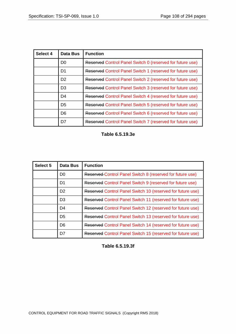
Specification: TSI-SP-069, Issue 1.0 Page 108 of 294 pages
Select 4 Data Bus Function
D0 Reserved Control Panel Switch 0 (reserved for future use)
D1 Reserved Control Panel Switch 1 (reserved for future use)
D2 Reserved Control Panel Switch 2 (reserved for future use)
D3 Reserved Control Panel Switch 3 (reserved for future use)
D4 Reserved Control Panel Switch 4 (reserved for future use)
D5 Reserved Control Panel Switch 5 (reserved for future use)
D6 Reserved Control Panel Switch 6 (reserved for future use)
D7 Reserved Control Panel Switch 7 (reserved for future use)
Table 6.5.19.3e
Select 5 Data Bus Function
D0 Reserved Control Panel Switch 8 (reserved for future use)
D1 Reserved Control Panel Switch 9 (reserved for future use)
D2 Reserved Control Panel Switch 10 (reserved for future use)
D3 Reserved Control Panel Switch 11 (reserved for future use)
D4 Reserved Control Panel Switch 12 (reserved for future use)
D5 Reserved Control Panel Switch 13 (reserved for future use)
D6 Reserved Control Panel Switch 14 (reserved for future use)
D7 Reserved Control Panel Switch 15 (reserved for future use)
Table 6.5.19.3f
CONTROL EQUIPMENT FOR ROAD TRAFFIC SIGNALS (Copyright RMS 2018)

Specification: TSI-SP-069, Issue 1.0 Page 109 of 294 pages
Select 6 Data Bus Function
D0 Facility Switch Contact A Status
D1 Facility Switch Contact B Status
D2 Facility Switch Contact C Status
D3 Facility Switch Connector Loop Status
D4 Flasher Unit Connector Loop Status
D5 Master Relay Connector Loop Status
D6 Master Relay Status
D7 Auxiliary Relay Status
Table 6.5.19.3g
Select 7 Data Bus Function
D0 Reserved Control Panel Connector Loop Status
D1 Light Sensor Connector Loop Status
D2 Gas Sensor Connector Loop Status
D3 Site ID Connector Loop Status
D4 Door Switch Connector Loop Status
D5 Door Switch status
D6 Unused Housing Electrical Code Encoder Connector Loop Status
D7 Unused Lamp Dimming Signal Generator Connector Loop Status
Table 6.5.19.3h
6.5.19.4 Noise Immunity
The interface circuits for reading the Site ID bus shall be designed with adequate hysteresis to provide effective rejection of electrical noise present in the housing.
6.5.19.5 Isolation
The interface circuits for the Site ID bus and the Select Line output interface circuits shall effectively isolate the controller logic circuits from the conditions specified in Clause 6.5.1.1.
CONTROL EQUIPMENT FOR ROAD TRAFFIC SIGNALS (Copyright RMS 2018)

Specification: TSI-SP-069, Issue 1.0 Page 110 of 294 pages
6.5.19.6 Site ID Connector to the Logic Module (XID)
The front panel connector at the Logic Module for all connections between the Logic Module and the Site Identification Encoder shall be a 44 pin female Miniature Double Density "D" type connector.
The pin connections for the Site Identification Encoder connector shall be as specified in Table F.6 in Appendix F.
6.5.19.7 Coding for Site Identification Encoder Connector
The mating connector for the Site Identification Encoder shall be uniquely identifiable by the control program.
The coding link for the Site Identification Encoder connector shall be fitted on the Site Identification Encoder printed circuit board, thereby allowing the control logic to sense that the connectors are mated at the Logic Module and at the Site Identification Encoder.
6.5.20 No Longer Used Control Panel (Reserved for Future Use)
Section deleted in Amendment 2
6.5.20.1 General
NOTE: This Control Panel is provision reserved for future use.
The Control Panel may have up to sixteen (16) switches, such as a keypad, and may have a number of LED indicators.
The Control Panel switches can be read by means of the Site ID Bus and do not require any further interface circuits.
The Site Identification Encoder and wiring make provision for two (2) LED Strobe Lines (namely LED A and LED B) which may be used to light LED indicators or used as strobes to latch display data from the Site ID Bus to light banks of LED indicators on the Control Panel. Refer to drawing VE 533-17.
NOTE: The Control Panel is interfaced to the Logic Module via the Site Identification Encoder, (Clause 7.13).
6.5.20.2 Isolation
The output interface circuits for the Control Panel LED Strobe Lines (if provided) shall effectively isolate the controller logic circuits from the conditions specified in Clause 6.5.1.1.
6.5.21 Electronic Facility Switch
6.5.21.1 General
The Logic Module shall provide an EIA 232 full-duplex serial link to the Electronic Facility Switch. The wiring connection to the Electronic Facility Switch shall be via the Site Identification Encoder circuit card. Refer to drawing VE533-17.
CONTROL EQUIPMENT FOR ROAD TRAFFIC SIGNALS (Copyright RMS 2018)
Specification: TSI-SP-069, Issue 1.0 Page 111 of 294 pages
NOTE: This specification makes provision for an electronic device with a serial data interface to be used for the Facility Switch in place of a mechanical switch. An amendment will be made to this specification in the future to specify the electronic device.
6.5.21.2 Isolation
The interface circuits shall effectively isolate the controller logic circuits from the conditions specified in Clause 6.5.1.1.
6.5.22 Vehicle Detection System
6.5.22.1 General
This Specification makes provision for the detection of vehicles to be achieved by a separate Vehicle Detection System complying with Specification VDS/1. The data from the Vehicle Detection System shall be passed to the Logic Module over a high-speed serial link.
The Vehicle Detection System may use loop detectors, video cameras, or any other suitable technology for the detection of vehicles.
6.5.22.2 Communications Channel
The communications channel between the Logic Module and the Vehicle Detection System shall be a full duplex high-speed serial link.
The high-speed communications channel shall operate in accordance with the EIA 485 standard for physical interconnection, allowing multiple Vehicle Detection Systems to share the same communications channel.
Refer to drawing VE533-21 for the electrical arrangement.
The Logic Module shall provide a 120 ohm resistor for bus termination at the receiver input to the Logic Module. The Vehicle Detection System is required to provide a similar termination at its receive input.
6.5.22.3 Communications Protocol
The data link layer protocol for the communications channel shall conform to the High Level Data Link Control (HDLC) protocol, (ISO/IEC 3309), operating in the asynchronous mode, (ie start/stop transmission as described in ISO/IEC 3309). The character format shall be: one start bit, 8 data bits, no parity bit and one stop bit.
The parameters for the communications port shall be specified by Hand Held Terminal commands and stored in the System EEPROM.
6.5.22.4 Isolation
The communications channel interface circuits shall effectively isolate the controller logic circuits from the conditions specified in Clause 6.5.1.1.
CONTROL EQUIPMENT FOR ROAD TRAFFIC SIGNALS (Copyright RMS 2018)
Specification: TSI-SP-069, Issue 1.0 Page 112 of 294 pages
6.5.22.5 Connector (XDS)
The front panel connector at the Logic Module for all connections between the Logic Module and the Vehicle Detector System shall be a 15 pin female Miniature "D" type connector.
The pin connections for the Vehicle Detector System connector shall be as specified in Table F.2 in Appendix F.
6.5.22.6 Coding for Vehicle Detection System Connector
The mating connector for the Vehicle Detection System shall be uniquely identifiable by the control program.
The wander lead connected to the Vehicle Detection System will provide a logic ground at pin 10 to allow the control program to sense that the Logic Module is connected to the Vehicle Detection System.
6.5.23 SCATS Modem
6.5.23.1 General
The control equipment shall provide a modem internal to the equipment, for communicating with the SCATS master over private telecommunications lines the Public Switched Telephone Network (PSTN).
The serial communications link shall also be accessible at the front panel of the controller at EIA 232 levels to allow external communications equipment to be used rather than the internal modem.
The selection of either the internal modem, or its EIA-232 port, or the Ethernet port for SCATS Communications (XNS) referred to in Clause 6.5.27, as the active means for communicating with the SCATS master shall be specified by a Hand Held Terminal command.
The internal modem shall be automatically disabled when the EIA 232 port is used to interface to external communications equipment.
In particular, the EIA 232 port shall allow the controller to communicate with the SCATS master by means of any of the following:
(a) auto-dial/auto-answer modem over the Public Switched Telephone Network (PSTN);
(b) ISDN interface equipment;
(c) DDS interface equipment;
(d) fibre optic interface equipment;
(e) radio communications equipment;
(f) modem for multi drop connection.
CONTROL EQUIPMENT FOR ROAD TRAFFIC SIGNALS (Copyright RMS 2018)

Specification: TSI-SP-069, Issue 1.0 Page 113 of 294 pages
When external equipment is used to provide communications to the master, the external equipment type and communications protocol required shall be specified by a Hand Held Terminal command, and stored in the System Data EEPROM.
NOTE: The external modem will be a type responding to the Hayes (AT) Commands. There is no requirement to supply the external modem with the equipment.
NOTE: In the following clauses, any of the above communications methods requiring external equipment is regarded as being equivalent to communications using an external modem.
NOTE: Refer to Clause 7.14 for details of the Line Isolation Unit Telecommunications Line Transient Protection Unit for connection of a telecommunications line.
6.5.23.2 Private Line Communications Network Topology
The control equipment shall be designed to operate in a star communications system using a dedicated point-to-point voice-grade twisted pair telecommunications PSTN line between each controller and a SCATS master.
The equipment shall make provision for an external modem to be used for multi drop communications with up to eight (8) controllers sharing the same communications line.
Loss of mains supply to, or failure of, one or more controllers on the multi-drop line shall not affect communications to other controllers on the multi-drop line.
The multi-drop communications shall operate in the "eaves drop" configuration. That is, the communications data shall not be received and regenerated at each controller for transmission to the next controller in the multi drop group.
In addition, the design shall be able to also operate in a star communications system using a dedicated point-to-point voice-grade twisted telecommunications line between each controller and a SCATS master.
6.5.23.3 Internal Modem Communications Standards
The internal modem shall operate in answer-mode in accordance with the ITU T V.34 standard.
If the internal modem makes provision for multiple communications standards, then the standard used for a particular installation shall be specified by the control program in accordance with data stored in the System Data EEPROM. Hand Held Terminal commands shall be provided to enter and modify the communications parameters in the System Data EEPROM.
NOTE: It is desirable for the internal modem to make provision for operation in answer mode in accordance with the Bell 103 standard for backward compatibility with SCATS versions prior to SCATS Version 7.
NOTE: The Bell 103 standard specifies Frequency Shift Keyed (FSK) modulation and demodulation with the transmit frequencies given in Table 6.5.23.3.
CONTROL EQUIPMENT FOR ROAD TRAFFIC SIGNALS (Copyright RMS 2018)
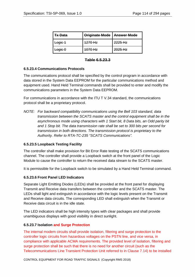
Specification: TSI-SP-069, Issue 1.0 Page 114 of 294 pages
Tx Data Originate Mode Answer Mode
Logic 1 1270 Hz 2225 Hz
Logic 0 1070 Hz 2025 Hz
Table 6.5.23.3
6.5.23.4 Communications Protocols
The communications protocol shall be specified by the control program in accordance with data stored in the System Data EEPROM for the particular communications method and equipment used. Hand Held Terminal commands shall be provided to enter and modify the communications parameters in the System Data EEPROM.
For communications in accordance with the ITU T V.34 standard, the communications protocol shall be a proprietary protocol.
NOTE: For backward compatibility communications using the Bell 103 standard, data transmission between the SCATS master and the control equipment shall be in the asynchronous mode using characters with 1 Start bit, 8 Data bits, an Odd parity bit and 1 Stop bit. The data transmission rate shall be set to 300 bits per second for transmission in both directions. The transmission protocol is proprietary to the Authority. Refer to RTA-TC-235 “SCATS Communications”.
6.5.23.5 Loopback Testing Facility
The controller shall make provision for Bit Error Rate testing of the SCATS communications channel. The controller shall provide a Loopback switch at the front panel of the Logic Module to cause the controller to return the received data stream to the SCATS master.
It is permissible for the Loopback switch to be simulated by a Hand Held Terminal command.
6.5.23.6 Front Panel LED Indicators
Separate Light Emitting Diodes (LEDs) shall be provided at the front panel for displaying Transmit and Receive data transfers between the controller and the SCATS master. The LEDs shall light and extinguish in accordance with the logic levels present on the Transmit and Receive data circuits. The corresponding LED shall extinguish when the Transmit or Receive data circuit is in the idle state.
The LED indicators shall be high intensity types with clear packages and shall provide unambiguous displays with good visibility in direct sunlight.
6.5.23.7 Isolation and Surge Protection
The internal modem circuits shall provide isolation, filtering and surge protection to the controller logic circuits from hazardous voltages on the PSTN line, and vice versa, in compliance with applicable ACMA requirements. The provided level of isolation, filtering and surge protection shall be such that there is no need for another circuit (such as the Telecommunications Line Transient Protection Unit referred to in Clause 7.14) to be installed
CONTROL EQUIPMENT FOR ROAD TRAFFIC SIGNALS (Copyright RMS 2018)
Specification: TSI-SP-069, Issue 1.0 Page 115 of 294 pages
between the internal modem circuits and the PSTN line to provide or complement the line isolation, filtering and surge protection.
The serial port interface circuits shall effectively isolate the controller logic circuits from the conditions specified in Clause 6.5.1.1.
6.5.23.8 SCATS Modem Connector (XM)
The SCATS telecommunications line connector shall be accessible at the front panel of the equipment.
The SCATS modem connector shall be used for connection of the EIA-232 signals to an external modem or other external equipment.
The front panel connector at the Logic Module for all connections to the SCATS modem shall be a 25 pin male Miniature "D" type connector.
The SCATS modem connector shall be accessible at the front panel of the Logic Module.
The same connector at the front panel shall be used for connection of the telecommunications line to the internal modem, and the EIA 232 signals to the external modem or other external equipment.
The connector shall be a 25 pin male Miniature “D” type connector.
The pin connections for the SCATS modem connector shall be as specified in Table F.8 in Appendix F.
6.5.23.9 PSTN Modem Connector (XRJ)
The PSTN modem connector shall be used for connection of a PSTN telephone line to the internal modem of the control equipment.
The PSTN modem connector shall be accessible at the front panel of the Logic Module.
The connector shall be a 6P2C (RJ11) connector socket.
The pin connections for the PSTN modem connector shall be as specified in Table F.19 in Appendix F.
6.5.24 SCATS Portable Terminal (TTY) Serial Port
6.5.24.1 General
The SCATS Portable Terminal (TTY) serial port allows an operator to communicate with the SCATS master via the communications channel.
The control equipment shall interface to the SCATS Portable Terminal at EIA 232 signal levels.
CONTROL EQUIPMENT FOR ROAD TRAFFIC SIGNALS (Copyright RMS 2018)
Specification: TSI-SP-069, Issue 1.0 Page 116 of 294 pages
6.5.24.2 Serial Port Parameters
The serial port parameters shall be set automatically by the control program. The default parameters shall be alterable by a Hand Held Terminal command and stored in the System Data EEPROM.
Data transmission between the SCATS Portable Terminal and the controller shall be in the asynchronous mode using characters with 1 Start bit, 8 Data bits, no parity bit and 1 Stop bit.
The default data transmission rate shall be 9600 bps in both directions.
The transmission protocol is proprietary to the Authority.
6.5.24.3 Standard Drawing
The interface characteristics for the serial port shall be in accordance with Drawing VE533-20.
6.5.24.4 Isolation
The serial port interface circuits shall effectively isolate the controller logic circuits from the conditions specified in Clause 6.5.1.1.
6.5.24.5 SCATS Portable Terminal Connector (TTY)
The SCATS Portable Terminal connector shall be accessible at the front panel of the equipment.
The front panel connector at the Logic Module for all connections to the SCATS Portable Terminal shall be a 25 pin female Miniature "D" type connector.
The pin connections for the SCATS Portable Terminal connector shall be as specified in Table F.13 in Appendix F. Refer to Drawing VE533-20.
6.5.25 Hand Held Terminal (HHT) Serial Port
6.5.25.1 General
The Hand Held Terminal (HHT) serial port allows an operator to communicate with the control equipment.
The control equipment shall interface to the HHT at EIA 232 signal levels.
6.5.25.2 Serial Port Parameters
The serial port parameters shall be set by the control program.
Data transmission between the HHT and the controller shall be in the asynchronous mode using characters with 1 Start bit, 8 Data bits, no parity bit and 1 Stop bit.
The default data transmission rate shall be set to 9600 bits per second for transmission in both directions.
The transmission protocol is proprietary to the Authority.
CONTROL EQUIPMENT FOR ROAD TRAFFIC SIGNALS (Copyright RMS 2018)
Specification: TSI-SP-069, Issue 1.0 Page 117 of 294 pages
6.5.25.3 Standard Drawing
The interface characteristics of the serial port shall be in accordance with Drawing VE533-15.
6.5.25.4 Current Limit Protection
The d.c. supply to the HHT shall be nominally 12 V at up to 85 mA, and shall be protected against overload by electronic current limit circuitry.
The d.c. supply shall recover automatically when the overload condition (eg. short circuit) is removed. That is, it shall not be necessary to remove the mains supply from the equipment, or to require any other action which will cause the signal lamps to switch off, in order to restore the d.c. supply.
NOTE: It is not permissible for the d.c. supply to be protected by a fuse or similar device which must be replaced to restore the supply voltage.
6.5.25.5 Isolation
The serial port interface circuits shall effectively isolate the controller logic circuits from the conditions specified in Clause 6.5.1.1.
6.5.25.6 Hand Held Terminal Connector (HHT)
The Hand Held Terminal connector shall be accessible at the front panel of the equipment.
The front panel connector at the Logic Module for all connections to the Hand Held Terminal shall be a 9 pin male Miniature "D" type connector.
The pin connections for the SCATS Terminal connector shall be as specified in Table F.5 in Appendix F. Refer to Drawing VE533-15.
6.5.26 Intelligent Transportation Systems Serial Ports
6.5.26.1 General
The controller shall provide four (4) serial ports for Intelligent Transportation Systems (ITS) applications.
The control equipment ports shall interface to ITS equipment as follows:
(a) ITS Port 1 at EIA 232 signal levels;
(b) ITS Port 2 at EIA 232 signal levels;
(c) ITS Port 3 at EIA 485 signal levels; and
(d) ITS Port 4 at EIA 485 signal levels.
NOTE: It is permissible for the ITS ports to be provided on a separate plug-in module.
CONTROL EQUIPMENT FOR ROAD TRAFFIC SIGNALS (Copyright RMS 2018)

Specification: TSI-SP-069, Issue 1.0 Page 118 of 294 pages
6.5.26.2 Serial Port Parameters
The serial port parameters for each of the ports shall be separately set by the control program in accordance with data stored in the System Data EEPROM. Hand Held Terminal commands shall be provided to enter and modify the communications parameters for each serial port in the System Data EEPROM.
Communications between the ITS equipment and the controller shall be in the asynchronous mode. The transmission protocol is proprietary to the Authority.
6.5.26.3 Standard Drawings
The interface characteristics for the ITS serial ports shall be in accordance with:
(a) Drawing VE533-13 for Ports 1 and 2; and
(b) Drawing VE533-14 for Ports 3 and 4.
6.5.26.4 Isolation
The serial port interface circuits shall effectively isolate the controller logic circuits from the conditions specified in Clause 6.5.1.1.
6.5.26.5 ITS Ports 1 and 2 Connectors (XTSA, XTSB)
The connectors for the ITS ports shall be accessible at the front panel of the equipment.
The front panel connectors at the Logic Module for all connections to each of the ITS Ports 1 and 2 shall be 15 pin male Miniature "D" type connectors.
The pin connections for the ITS Port 1and 2 connectors shall be as specified in Table F.11 in Appendix F. Refer to Drawing VE533-13.
The mating connectors for the ITS ports shall be uniquely identifiable by the control program.
The coding links in the wander lead connectors for ITS Ports 1 and 2 shall be:
Connector ITS Port Coding Link
XTSA Port 1 11 to 12
XTSB Port 2 12 to 13
Table 6.5.26.5
6.5.26.6 ITS Ports 3 and 4 Connectors (XTSC, XTSD)
The connectors for the ITS ports shall be accessible at the front panel of the equipment.
The front panel connectors at the Logic Module for all connections to each of the ITS Ports 3 and 4 shall be 15 pin female Miniature Double Density "D" type connectors.
CONTROL EQUIPMENT FOR ROAD TRAFFIC SIGNALS (Copyright RMS 2018)

Specification: TSI-SP-069, Issue 1.0 Page 119 of 294 pages
The pin connections for the ITS Port 3 and 4 connectors shall be as specified in Table F.12 in Appendix F. Refer to Drawing VE533-14.
The mating connectors for the ITS ports shall be uniquely identifiable by the control program.
The coding links in the wander lead connectors for ITS Ports 3 and 4 shall be:
Connector ITS Port Coding Link
XTSC Port 3 3 to 8
XTSD Port 4 8 to 13
Table 6.5.26.6
6.5.27 Ethernet Port for SCATS Communications (XNS)
6.5.27.1 General
The Ethernet port (XNS) allows a network communications device to be used for communication between the controller and the SCATS master. It shall not be possible for this Ethernet port to be used for any other purposes.
NOTE: The network communications device may be an external device, (e.g. a voice-band, ADSL or fibre optic modem/router), or a plug-in communications module with a suitable built-in modem, which connects to a suitable communication network linking up to the SCATS master,
The selection of either this Ethernet Port (XNS), or the SCATS modem or its EIA-232 port (see Clause 6.5.23.1), as the active means for communication with the SCATS master shall be specified by a Hand Held Terminal command.
The Ethernet port XNS shall support both IPv4 and IPv6 addresses.
6.5.27.2 MAC Address
The Ethernet port shall have a unique MAC address.
6.5.27.3 MDI/MDIX Switchover
The Ethernet port shall provide Auto-MDI/MDIX switchover. The connector of the Ethernet port shall be an 8P8C jack compliant with ISO/IEC 8877. The connector wiring shall be compliant with the T568A wiring scheme in AS/NZS 3080.
6.5.27.4 IP Address
The Ethernet port shall be user configurable to use a static IP address, or a dynamic IP address assigned by an external DHCP server. There is no requirement for the Ethernet port to provide DHCP server function.
CONTROL EQUIPMENT FOR ROAD TRAFFIC SIGNALS (Copyright RMS 2018)

Specification: TSI-SP-069, Issue 1.0 Page 120 of 294 pages
6.5.28 Ethernet Port for Web-based User Interface (XNW)
6.5.28.1 General
The Ethernet port (XNW) allows an operator to communicate with the control equipment using a web-based user interface on a portable computer.
6.5.28.2 MAC Address
The Ethernet port shall have a unique MAC address.
The Ethernet port XNW shall support both IPv4 and IPv6 addresses.
6.5.28.3 MDI/MDIX Switchover
The Ethernet port shall provide Auto-MDI/MDIX switchover. The connector of the Ethernet port shall be an 8P8C jack compliant with ISO/IEC 8877. The connector wiring shall be compliant with the T568A wiring scheme in AS/NZS 3080.
6.5.28.4 IP Address
The Ethernet port shall be user configurable to use a static IP address, or a dynamic IP address assigned by an external DHCP server. There is no requirement for the Ethernet port to provide DHCP server function.
6.5.29 USB Port (XUP)
6.5.29.1 General
The USB Port (XUP) allows an operator to connect a USB flash drive and use it as a source of data and programs, or a storage medium.
Provisions shall be made to support all of the three data rates, namely high-speed, full-speed and low-speed, of the USB 2.0 connection scheme.
6.5.29.2 Drivers
The controller shall be provided with all necessary USB drivers for the functions referred to in Clause 6.2.17.3.
NOTE: It would be preferable if the USB Port can support more than one USB connection via a USB hub.
6.5.30 Dimming by Control Signal – Signalling and Monitor Interface
6.5.30.1 General
The Logic Module shall provide circuits in its CPU module to control and monitor the operation of the Lamp Dimming Signal Generator (Clause 7.17). This Signal Generator module is located in the controller housing and generates the control signal for dimming lantern aspects. The control and monitor signals require interface circuits within the Logic Module and shall comprise the following:
(c) Two Dimming Control outputs; and
(d) A Dimming Control Monitor input.
CONTROL EQUIPMENT FOR ROAD TRAFFIC SIGNALS (Copyright RMS 2018)

Specification: TSI-SP-069, Issue 1.0 Page 121 of 294 pages
NOTE: The Signalling and Monitor Interface is connected to the Lamp Dimming Signal Generator (Clause 7.17) in the Wired Housing via the Controller Logic Module Connector (ZID) on the Site Identification Encoder (Clause 7.13.11). Refer to the Site Identification Encoder circuit, Drawing VE 533-17 for pin connections.
NOTE: Refer to Clause 6.6.3.2 for information on dimming methods.
6.5.30.2 Dimming Control Outputs
The Dimming Control outputs shall provide for the control of the Lamp Dimming Signal Generator (Clause 7.17) to operate in one of the following relevant states as shown in Table 6.5.30.2 below.
State of Dimming Control Output 1
State of Dimming Control Output 2
Required Resultant State of Control
Operation
Active Active Control Disabled NOTE
Active Not Active Dimmed Operation
Not Active Active Undimmed Operation
Not Active Not Active Control Disabled NOTE
NOTE: The “Control Disabled” state shall result in the Lamp Dimming Signal Generator connecting its lamp dimming control signal output to the Neutral terminal of the lamp supply.
Table 6.5.30.2
The Dimming Control outputs shall conform to the following requirements:
(a) With the output active (to signify dimmed operation for lantern aspects), the open-circuit voltage (Thevenin voltage) sourced from the output shall be nominally 12 V d.c. and shall not exceed 15V d.c.;
(b) The output impedance (Thevenin impedance) shall not be less than 1.2 k-ohm, and shall not be greater than 1.8 k-ohm;
(c) With the output inactive (to signify undimmed operation for lantern aspects), the output voltage shall not exceed 0.5 V d.c.;
(d) The output circuitry shall provide protection as specified in Clause 6.5.1.1.
6.5.30.3 Dimming Control Monitor Input
The Dimming Control Monitor input shall interface the feedback signal provided by Lamp Dimming Signal Generator (Clause 7.17) in the Wired Housing.
6.6 Regulation and Dimming of Lamp Supply Voltage
CONTROL EQUIPMENT FOR ROAD TRAFFIC SIGNALS (Copyright RMS 2018)

Specification: TSI-SP-069, Issue 1.0 Page 122 of 294 pages
6.6.1 Common Requirements for Regulation and Dimming
6.6.1.1 Regulation Method
The equipment shall provide regulation and dimming of the lamp supply voltage by means of continuously variable phase control of the incoming mains supply voltage for each signal group output.
NOTE: Refer to Clause 6.6.3.2 for dimming using a dedicated lamp dimming control signal.
Voltage regulation and/or dimming of the signal displays shall not be implemented by tap changing on a transformer.
6.6.1.2 Uniformity Requirements
The phase control of the incoming mains supply voltage shall not result in missing mains cycles to the signal lamps and shall not cause any observable irregularity in the signal displays.
The phase control process shall not cause any residual direct current (d.c.) in the lamp circuits or in the mains supply.
6.6.1.3 Per Signal Group Control
The r.m.s. voltage applied to the signal group loads shall be controlled by adjustment of the firing angle of the output TRIACs used to switch the signal lamps.
The firing angle for each TRIAC shall be separately controlled for each output.
NOTE: The controller Personality specifies separately for each aspect for each signal group whether regulation and/or dimming is enabled or disabled for each particular output.
6.6.2 Regulation of Lamp Supply Voltage
6.6.2.1 General
The lamp supply voltage shall be regulated to prevent over-voltage to the lamps during normal operation and under-voltage during dimmed operation.
NOTE: Over-voltage degrades lamp life; under-voltage reduces visibility and may also result in spurious conflict detection. The halogen cycle ceases in quartz halogen lamps when the lamp voltage falls below 90% of the nominal value, resulting in irreversible depositing of tungsten on the quartz envelope, with consequent degradation of light output.
6.6.2.2 Over-Voltage Limiting
While the signal displays are not dimmed, the controller shall limit the lamp voltage in accordance with the nominal lamp supply voltage specified in the CMODE entry in the controller Personality data.
CONTROL EQUIPMENT FOR ROAD TRAFFIC SIGNALS (Copyright RMS 2018)
Specification: TSI-SP-069, Issue 1.0 Page 123 of 294 pages
The equipment shall maintain the r.m.s. lamp supply voltage within ±2% of the specified nominal voltage while the incoming mains supply voltage is greater than the specified nominal lamp voltage.
NOTE: The CMODE entry specifies the nominal lamp supply voltage. Refer to RTA-TC-185 "RTA Standard Personality Reference Manual" for the format of the CMODE entry.
6.6.2.3 Regulation While Signals Are Dimmed
The controller shall regulate the r.m.s. lamp supply voltage to within ±2% of the specified nominal dimmed voltage while the signal displays are dimmed. Refer to Clause 6.6.3.
6.6.2.4 Regulation Response Time
The response time for adjusting the regulation of the lamp supply voltage shall be not more than ten (10) seconds. That is, the lamp supply voltage shall be regulated to within the specified tolerance within ten (10) seconds of a variation in the mains supply voltage.
6.6.3 Dimming of Signal Displays
6.6.3.1 General
The equipment shall provide dimmed operation of the signal displays subject to safety requirements related to the visibility of the signals.
NOTE: Dimmed operation of the signals significantly extends the lamp life.
Dimming of the signal displays shall be dependent upon the following conditions being satisfied simultaneously:
(a) Dimming enabled by the Personality data (Clause 6.6.3.3);
(b) The Light Sensor indicating "night" (Clause 6.6.3.5);
(c) The time of day being within a time zone for which dimming is permitted (Clause 6.6.3.7); and
(d) Absence of all fault conditions which preclude dimming (Clause 6.6.3.8).
NOTE: Hand Held Terminal commands are provided for specifying an override to ignore the Light Sensor, and for altering the thresholds for the Light Sensor. Refer to Clause 6.6.3.10.
6.6.3.2 Dimming Voltage Levels Methods
6.6.3.2.1 General
Dimming of the signal displays shall be implemented by one of the methods below, as provided for in the controller Personality data and field wiring”
(a) Reduced lamp supply voltage levels (Clause 6.6.3.2.2);
(b) Using a dedicated lamp dimming control signal for controlling the dimming of compatible traffic signal lanterns (Clause 6.6.3.2.3).
CONTROL EQUIPMENT FOR ROAD TRAFFIC SIGNALS (Copyright RMS 2018)

Specification: TSI-SP-069, Issue 1.0 Page 124 of 294 pages
Where dimming method (b) is used, the control equipment shall maintain the lamp supply voltage at its nominal value for undimmed operation during dimming operation.
6.6.3.2.2 Dimming by Reduced Lamp Voltage
The equipment shall provide two levels of dimming for each nominal lamp supply voltage specified in the CMODE entry in the controller Personality data.
With a nominal lamp supply voltage of 240 V r.m.s., the default lamp supply voltages for the two dimming levels shall be:
(a) Level 1 90% of the nominal lamp supply voltage; and
(b) Level 2 80% of the nominal lamp supply voltage.
NOTE: Level 1 is intended for dimming quartz halogen (or other Extra-Low Voltage) lamps and Level 2 for dimming incandescent lamps and LED lantern aspects.
The default values for the dimming voltage levels shall be overridden by data in the DIMVLT entry in the controller Personality data. The DIMVLT entry shall be ignored if it specifies a dimming voltage lower than 75% of the nominal lamp supply voltage specified in the CMODE entry in the controller Personality data.
NOTE: The DIMVLT entry is ignored if it specifies a voltage which may result in detection of spurious conflicts due to insufficient voltage on Red signal aspects.
NOTE: Refer to the document RTA-TC-185 "RTA Standard Personality Reference Manual" for the format of the CMODE and DIMVLT entries in the controller Personality data.
6.6.3.2.3 Dimming by Control Signal
The dimming control signal shall be of the following form:
(a) For dimmed operation - be the a reduced voltage at 50% of nominal lamp supply voltage;
(b) For undimmed operation – be a reduced voltage at 50% of the nominal lamp supply voltage; and
(c) For disabled operation – be connected to Neutral of the lamp supply.
Where the control voltage is not derived from the lamp supply the control voltages shall be constrained to within ±10% of the nominal values.
NOTE: Refer to Clause 6.5.30 for requirements for signalling and monitor interface for dimming by control signal operation. Refer to Clause 7.17 for requirements for the lamp dimming signal generator.
NOTE: Refer to Drawing VM625-22 for locations of the dimming control signal on field terminals.”
CONTROL EQUIPMENT FOR ROAD TRAFFIC SIGNALS (Copyright RMS 2018)

Specification: TSI-SP-069, Issue 1.0 Page 125 of 294 pages
6.6.3.3 Dimming Enable
The equipment shall not dim the signal displays unless dimming is enabled by the CMODE entry in the controller Personality data.
The controller personality shall also separately specify enabling or disabling of dimming for each aspect colour of each signal group. In absence of this data the default state shall be dimming enabled for all aspect colours for all signal groups, subject to dimming being enabled by the CMODE entry.
6.6.3.4 Selection of the Dimming Level
The default dimming level (ie Level 1 or Level 2) shall be as specified by the CMODE entry in the controller Personality data.
Entries in the Condition Tables in the controller Personality data shall override the default dimming level specified by the CMODE entry.
Regardless of any other condition, entries in the Condition Tables in the controller Personality data shall have priority in forcing the signal displays to operate at full brightness (ie to cancel dimming).
6.6.3.5 Dimming Subject to Light Sensor
The equipment shall provide a Light Sensor and an appropriate software algorithm to detect and determine the ambient light level for operation of the dimming function (refer to Clause 7.15).
The signal displays shall not be dimmed while the Light Sensor is indicating ambient light conditions brighter than "night". Refer to Clause 6.6.3.6.
NOTE: The dimming function shall not be dependent upon the Light Sensor if the Light Sensor is specified to be ignored by a Hand Held Terminal command. Refer to Clause 6.6.3.10.
NOTE: The dimming function shall not be dependent upon the Light Sensor if so specified in the CMODE entry in the controller Personality data
6.6.3.6 Light Sensor Algorithm
The output state of the Light Sensor shall not be used directly to enable or cancel dimming of the signal displays.
The Light Sensor output shall be processed by an appropriate algorithm to prevent spurious changes detected by the Light Sensor from affecting the dimming state of the signals.
The algorithm for the Light Sensor shall provide an indication of "night" when the ambient light level at the Light Sensor is less than the preset threshold. The default threshold setting shall be 30 Lux.
The algorithm shall indicate "day" when the ambient light level rises above the preset threshold. The default threshold setting shall be 150 Lux.
CONTROL EQUIPMENT FOR ROAD TRAFFIC SIGNALS (Copyright RMS 2018)

Specification: TSI-SP-069, Issue 1.0 Page 126 of 294 pages
NOTE: The preset thresholds for "night" and "day" are alterable by Hand Held Terminal commands. Refer to Clause 6.6.3.10.
For light levels between the preset "night" and "day" thresholds, the algorithm shall maintain the last indication. That is, the algorithm shall provide hysteresis in changing the indication from one state to another.
After the algorithm has sensed that the Light Sensor is indicating "night", the algorithm shall provide a delay of 30 minutes before enabling dimming.
The algorithm for determining the ambient light conditions from the output of the Light Sensor shall provide a true indication of "night" or "day" regardless of any of the following occurrences:
(a) transient light, such as car headlights, incident on the Light Sensor;
(b) street lighting and/or shop lighting;
(c) eclipses;
(d) an object (eg. a person's hand) covering the Light Sensor for periods up to 4 minutes.
NOTE: It is permissible for the signal displays to remain at full brightness (that is, to not dim) in the presence of bright shop lighting.
The Light Sensor algorithm shall also be able to detect any of the following conditions and shall record an appropriate entry in the controller Fault/Error Log:
(a) The Light Sensor not plugged in;
(b) A faulty Light Sensor (ie no output);
(c) Incorrect output from the Light Sensor for the time of day;
(d) No change of state in the Light Sensor output during the preceding 24 hours.
The Light Sensor algorithm shall regard the Light Sensor as faulty, and shall not indicate "night", while any of the above conditions is in effect.
It is permissible for the Light Sensor algorithm to "learn" the ambient light conditions over a period of one or more days before it becomes effective in enabling dimming.
6.6.3.7 Dimming Subject to Time of Day
The signal displays shall not be dimmed if the controller clock time has not been set.
The data in the DIMDAT table in the controller Personality data specifies four time zones for each day, viz, Dawn, Day, Dusk and Night.
NOTE: Refer to the document RTA-TC-185 "RTA Standard Personality Reference Manual" for details of the DIMDAT Table.
Regardless of any other condition, the signal displays shall not be dimmed while the current clock time is within the Day time zone specified in the DIMDAT table in the controller Personality data.
CONTROL EQUIPMENT FOR ROAD TRAFFIC SIGNALS (Copyright RMS 2018)
Specification: TSI-SP-069, Issue 1.0 Page 127 of 294 pages
The signal displays shall be dimmed automatically when the clock time is within the Night time zone, subject to all other conditions being satisfied for enabling of dimming.
In the Dawn and Dusk time zones, the signal displays shall only be dimmed under control of entries in the Condition Tables in the controller Personality data, subject to all other conditions being satisfied for enabling of dimming.
If the data in the DIMDAT table is invalid, then the signal displays shall not be dimmed.
If the controller Personality does not provide any data for the DIMDAT table, then the control program shall assume default data for the DIMDAT table for the time zones specified in drawing VE533-12.
6.6.3.8 Prevention of Dimming
The controller shall not dim the signal displays following detection of any fault condition relating to the operation of the Light Sensor, until the fault is rectified.
Regardless of all other conditions, when dimming is subject to the Light Sensor, the controller shall not dim the signal displays unless the Light Sensor algorithm is indicating an ambient light level corresponding to "night".
Dimming of the signal displays shall be automatically cancelled when the Light Sensor algorithm changes its indication of the ambient light level from the "night" state to the "day" state. That is, the signal displays shall immediately commence transition to normal brightness, subject to the requirements specified in Clause 6.6.3.9.
6.6.3.9 Transition to/from Dimmed Operation
The equipment shall use an algorithm to provide a gradual transition to and from the dimmed state for signal group outputs over a period of the order of several 10 seconds up to one minute, where dimming is implemented by reduced lamp supply voltage levels.
NOTE: The intention is to avoid abrupt changes in brightness on the signal displays. The transition should be imperceptible.
6.6.3.10 Hand Held Terminal Commands
The controller shall provide a Hand Held Terminal command for changing the light threshold settings for the Light Sensor algorithm. The threshold for the "night" indication shall be alterable within the limits 30 Lux to 130 Lux. The threshold for the "day" indication shall be alterable within the limits 150 Lux to 250 Lux.
The controller shall provide a Hand Held Terminal command to cause the Light Sensor to be ignored in determining the conditions for dimming. That is, the command shall effectively override the CMODE entry in the Personality data specifying that dimming is subject to the Light Sensor. The HHT command shall store the override command in the system EEPROM.
The controller shall provide a Hand Held Terminal command to allow an operator to display:
(a) The threshold settings for "night" and "day" indications;
(b) Any override status to ignore the Light Sensor;
CONTROL EQUIPMENT FOR ROAD TRAFFIC SIGNALS (Copyright RMS 2018)
Specification: TSI-SP-069, Issue 1.0 Page 128 of 294 pages
(c) The current status of the Light Sensor (ie instantaneous status);
(d) The current status of the Light Sensor algorithm;
(e) The current status of the signal operation (ie. dimmed or normal operation); and
(f) The current r.m.s. lamp supply voltage.
NOTE: Refer to the document RTA-TC-220 "Hand-Held Terminal Operator's Manual" for user interface commands.
6.6.3.11 Monitoring of Dimming Operation Using Lamp Dimming Control Signal
The equipment shall conduct checks and tests to detect anomalies with lamp dimming operation using the lamp dimming control signal.
NOTE: Faults with dimming using a lamp dimming control signal can occur due to various reasons. Some examples are fault with the Lamp Dimming Signal Generator (Clause 7.17); fault with related internal wiring; and fault with the Lamp Dimming Signal field conductors such as shorting to ground, shorting to a lantern aspect, and missing, severed or discontinued connection.
Examples of checks and tests include the following:
(a) Monitor at intervals not exceeding 10 seconds the state of the lamp dimming control signal by measuring the lamp dimming control signal voltage;
(b) Compare at intervals not exceeding 10 seconds the lamp loads between the dimmed and undimmed states for each signal group colour to determine if there are differences to conclude abnormal operation.
NOTE: In dimmed operation, the load on each signal group would normally be more than 20% lower than that for undimmed operation.
In the event of detection of an anomaly, the equipment shall perform additional checks and measurements for confirmation.
Upon confirmation of the same anomaly, the equipment shall log an error with supporting information and continue operation.
6.7 Lamp Monitoring
6.7.1 General
The equipment shall provide a lamp monitoring function for learning the connected load for each signal group and reporting lamp failures when they occur.
The basic processes for the lamp monitoring function are:
(a) measuring, averaging and monitoring the r.m.s. lamp supply voltage;
(b) measuring, averaging and monitoring the real power for the connected loads for each aspect colour for each signal group;
(c) identifying the lamp dimming method used (that is, whether by reduced lamp supply voltage or using a lamp dimming control signal) for power measurements made in (b);
CONTROL EQUIPMENT FOR ROAD TRAFFIC SIGNALS (Copyright RMS 2018)

Specification: TSI-SP-069, Issue 1.0 Page 129 of 294 pages
(d) an algorithm for learning the connected load for each aspect colour for each signal group; and
(e) an algorithm for detecting and reporting the failure of lamps driven by the signal group outputs.
(f) an algorithm for detecting and reporting the potential failure of dimming using a lamp dimming control signal.
The measurements for the signal group loads may also be used by the conflict monitoring routines (Clause 6.8).
The measurements for the signal group loads may also be used as follows:
(a) For monitoring of dimming operation using the lamp dimming control signal (Clause 6.6.3.11); and
(b) By the conflict monitoring routines (Clause 6.8).
6.7.2 Measurements
6.7.2.1 Lamp Supply Voltage Measurements
The equipment shall measure the r.m.s. lamp supply voltage with an accuracy of ±2% or better.
The measuring circuitry shall perform a measurement on the lamp supply voltage simultaneously with every measurement of voltage and/or power and/or current for the signal group loads.
NOTE: Measuring the lamp supply voltage simultaneously with every signal group load measurement allows spurious measurements to be identified, such as may be caused by a mains brownout.
NOTE: Measuring the lamp supply voltage simultaneously with every signal group load measurement allows the correlation of the latter to the former, to provide better load tracking and monitoring for LED lanterns that may exhibit a non-linear characteristic. It also allows spurious measurements to be identified, such as may be caused by a mains brownout or a fault with dimming using a lamp dimming control signal.
Spurious lamp supply voltage measurements, such as due to transients or brownouts on the mains supply, shall be discarded together with the signal group load measurements for the same measuring cycle.
An algorithm shall be used to continuously average the r.m.s. measurements of the lamp supply voltage. The effective averaging time shall not be greater than 5 minutes.
The lamp supply voltage reported by the controller to operator requests, or in response to commands from the SCATS master, shall be the averaged r.m.s. lamp supply voltage rather than the instantaneous voltage reading obtained from a single measurement.
CONTROL EQUIPMENT FOR ROAD TRAFFIC SIGNALS (Copyright RMS 2018)
Specification: TSI-SP-069, Issue 1.0 Page 130 of 294 pages
6.7.2.2 Signal Group Power Measurements
The controller shall routinely measure the average real power for the load connected to each colour output of each signal group.
The measuring system for each signal colour shall be capable of measuring loads up to 1200300 W.
The tolerance for power measurements shall be ±5 W for loads up to 250 W, and ±2% for loads greater than 250 W up to the full rated lamp load.
The tolerance for power measurements shall be ±1.0 W for loads up to 100 W, and ±1.0% for loads greater than 100 W up to the full rated lamp load.
Power measurements shall be repeatable with an accuracy sufficient to reliably detect failure of a single lamp, using the threshold specified in Clause 6.7.4.2.
The algorithm used for measuring the loads shall measure real power. That is, the algorithm shall provide correct measurements of real power regardless of the power factor of the connected load.
The algorithm shall not assume, nor be dependent upon, the mains voltage supply being a true sinusoid.
The algorithm shall allow for incandescent lamp loads, transformer-driven quartz halogen (or other Extra-Low Voltage) lamp loads, LED lamp loads, and any combination of these.
The algorithm shall allow for a combination of variable load impedances that are dependent on the supply voltage, on the same signal group output. It is to be noted that the variable load impedances may exhibit fluctuating values over the full range of possible lamp supply voltages.
6.7.2.3 Integrity of Power Measurements
The load power measurements shall be continuously averaged to allow the controller to learn the currently connected load for each signal colour when the signal colour is energised. The averaging time shall be sufficiently long to prevent any of the following occurrences from producing any significant error in the learned load powers:
(a) Fluctuations in the mains supply voltage;
(b) Transient voltage surges or spikes in the mains supply;
(c) Transient brownouts in the mains supply;
(d) Supply Authority's switching tones;
(e) Inrush current associated with the switching of signal lamps;
(f) Surge currents due to arcing when a lamp filament ruptures;
(g) Reactive currents due to transformer leakage inductance; and
(h) Load fluctuations arising from Pedestrian Audio-tactile Signal driver units.
(i) Incorrect dimming due to a fault with Lamp Dimming Signal operation.
NOTE: Refer to Clauses 6.5.30 and 7.17 for Lamp Dimming Signal operation.
CONTROL EQUIPMENT FOR ROAD TRAFFIC SIGNALS (Copyright RMS 2018)

Specification: TSI-SP-069, Issue 1.0 Page 131 of 294 pages
The algorithm shall discard measurements for a signal group colour immediately following switch-on of that signal group colour, to preclude the effects of inrush currents from degrading the accuracy of the averaged measurements.
6.7.2.4 Reporting of Power Measurements
The controller shall report lamp loads, (in average watts), to the SCATS master and to the Hand Held Terminal upon operator request.
During dimmed operation with reduced lamp supply voltage, the controller shall use normalisation or scaling to report the effective lamp loads at the specified nominal lamp supply voltage (ie as for undimmed operation). The normalised lamp loads shall be reported with an accuracy within ±10%.
During dimmed operation with reduced lamp supply voltage, the controller shall use the actual measured lamp loads at the reduced supply voltage or under active lamp dimming signal control for the purpose of confirming if there is a lamp fault, but the controller shall report the values of effective lamp loads that would have been measured at the specified nominal lamp supply voltage (i.e. as for undimmed operation).
6.7.3 Learning Connected Loads
6.7.3.1 General
The algorithm for learning the lamp loads shall be continuously in effect while the equipment is operating with the signal lamps energised.
NOTE: During dimmed operation, the controller may use normalisation of measurements to provide lamp monitoring equivalent to the monitoring in the undimmed state. Alternatively it is permissible for the controller to use separate sets of references for lamp loads in the dimmed and undimmed states, however in such case special consideration is required for reporting of lamp faults when the signals change from dimmed to undimmed operation and vice-versa.
NOTE: It is permissible for the controller to use separate sets of references for lamp loads in the dimmed and undimmed states.
The learning algorithm shall compensate for the reduced lamp supply voltage when the signal displays are dimmed.
The learning algorithm shall be suspended in the absence of supply voltage to the signal lamps.
The learning algorithm shall compensate for variations in the lamp supply voltage in operation, the reduced lamp voltage when signal displays are dimmed by a reduced lamp voltage, and possible combined variable load impedances that are dependent on the supply voltage and presented by LED based and other lamp loads.
NOTE: The following clauses specify the basic requirements for lamp monitoring, however, the Supplier may develop more sophisticated algorithms which provide superior performance.
CONTROL EQUIPMENT FOR ROAD TRAFFIC SIGNALS (Copyright RMS 2018)
Specification: TSI-SP-069, Issue 1.0 Page 132 of 294 pages
6.7.3.2 Load References
As a minimum, the equipment shall provide storage for the primary and secondary references for the total connected load to each aspect colour of each signal group.
The primary reference store shall contain the highest total load connected to each aspect colour of each signal group, as learned by the algorithm in the absence of lamp faults. The primary reference store shall contain the highest total load connected to each aspect colour of each signal group for each lamp supply voltage value or range of values, as learned by the algorithm in the absence of lamp faults. The primary reference is used for comparison with the current load to determine whether a lamp fault has occurred.
The secondary reference store shall contain the total load connected to each aspect colour of each signal group, as learned by the algorithm in the presence of lamp faults. The secondary reference store shall contain the total load connected to each aspect colour of each signal group for each lamp supply voltage value or range of values, as learned by the algorithm in the presence of lamp faults. The secondary reference is used for comparison with the current load to determine whether a subsequent lamp fault has occurred.
In the event of a subsequent lamp fault, the lamp fault shall be processed and the secondary reference updated to reflect the new reference for the current load.
The learned values for the lamp loads shall be preserved in the absence of the mains supply voltage.
NOTE: The primary reference reflects the "expected" loads in the absence of lamp faults. The secondary reference reflects the "current reference" in the presence of lamp faults.
NOTE: Separate storage is required for each colour for each signal group for maintaining the current average power measured in each signal cycle, which is compared to either the primary or secondary reference for the detection of new lamp faults.
6.7.3.3 Learning Load References
The learning algorithm shall correct the learned lamp load references to compensate for small variations in lamps, after applying normalisation for any variations in the lamp supply voltage.
The learning algorithm shall correct the learned lamp load references to compensate for variations in the load device after replacement of one or more lamps or lanterns.
NOTE: For example, replacement of one or more lamps for a signal group colour may result in a slightly different maximum load for that signal group colour due to variations in individual lamps. The learning algorithm shall correct the learned load references in such a case.
If the current lamp load for a signal aspect is greater than the previously learned reference load then the learning algorithm shall learn the new load.
CONTROL EQUIPMENT FOR ROAD TRAFFIC SIGNALS (Copyright RMS 2018)
Specification: TSI-SP-069, Issue 1.0 Page 133 of 294 pages
If the current lamp load for a signal aspect is not more than 10 W 8% or 2.0 W (whichever is higher) lower than the previously learned reference load, then the learning algorithm shall learn the new lamp load.
If the current lamp load for a signal aspect is more than 10 W 8% or 2.0 W (whichever is higher) lower than the previously learned reference load then the learning algorithm shall not alter the previously learned primary reference load.
The learning algorithm shall be designed to learn the loads for the Red and Green colours within an accumulated 1 minute of actual energisation time for those aspects.
The learning algorithm shall be designed to learn the loads under each lamp supply voltage value or range of values (voltage step) for the Red and Green colours within an accumulated 30 seconds of actual energisation time for those aspects at that lamp supply voltage step.
A "faster" learning algorithm shall be employed for the Yellow colour such that the loads shall be learned within an accumulated 10 seconds of actual energisation time for those aspects at each applicable lamp supply voltage step.
NOTE: It is permissible for the learning time to be longer for a signal group aspect which provides only a flashing display (ie the only steady display for the aspect is an Off state).
6.7.3.4 Abnormal Corrections to Load References
It is permissible for the learning algorithm to learn and report a load higher than the actual connected lamp load in the presence of sustained periods of high power loads connected by maintenance staff, for example, electric drills and electric jack hammers powered from the Green colour of a signal group.
It is permissible for the learning algorithm to learn and report a load higher than the actual connected lamp load in the presence of leakage currents, such as on terminal blocks in lanterns or top-mounting assemblies due to ingress of water.
In cases where the learning algorithm has learned a higher load than the actual lamp load due to an abnormal situation, it is permissible for the controller to report lamp faults for the affected signal colours when the abnormal load situation ceases.
6.7.4 Detecting and Reporting Lamp Faults
6.7.4.1 Conditions for Detecting Lamp Faults
The controller shall not detect or report lamp failures for a signal group colour until the load reference for that signal group colour has been established.
The controller shall not detect or report lamp failures for a signal group colour until one of the following conditions is met:
(a) The load reference at that particular lamp supply voltage has been established for that signal group colour;
CONTROL EQUIPMENT FOR ROAD TRAFFIC SIGNALS (Copyright RMS 2018)

Specification: TSI-SP-069, Issue 1.0 Page 134 of 294 pages
(b) A minimum of two load values at different lamp supply voltages for that signal group colour have been established, which allows interpolation or extrapolation for the other lamp supply voltages.
NOTE: It is permissible to use interpolation, or extrapolation as appropriate, for estimating reference lamp loads at other lamp supply voltages that have not yet had reference lamp loads established, for the purpose of detecting and reporting lamp faults.
Since the learning of lamp loads is dependent on the controller cycling, it is preferable for the controller to detect and report lamp faults for signal group colours whose loads have been established, even though the learning process may still be in progress for other signal group colours.
6.7.4.2 Detection of Lamp Faults
If the measured load for a signal group colour, (after averaging and normalisation), is more than 15 W lower than the reference load, then the controller shall report a lamp fault for that
signal group colour. If the measured load for a signal group colour, (after averaging, and mapping to the specified nominal lamp supply voltage with appropriate scaling), is more than
10% or 2.5 W (whichever is higher) lower than the reference load, then the controller shall report a lamp fault for that signal group colour. Each transitional change in the load power
greater than this threshold shall be considered to represent a single lamp fault event.
After detection of a lamp fault for a signal group colour, the controller shall use the secondary reference for the remaining connected lamp load for that signal group colour.
After detection of a lamp fault for a signal group colour, the controller shall use the secondary reference for the remaining connected lamp load for that signal group colour and that lamp supply voltage or range of voltages. For other unpopulated lamp supply voltages or ranges of values in the primary reference, the controller shall continue learning lamp loads and populating those spaces in the primary reference.
Any further decreases in measured load for the signal group colour, of magnitude greater than 15 W 10% of the reference load or 2.5 W (whichever is higher), shall be reported as another lamp fault for that signal group colour and the secondary reference shall be updated with the remaining load for that signal group colour. This process shall be repetitive.
The algorithm for detecting lamp faults shall not generate more than one lamp fault event from a single lamp failure.
NOTE: If separate sets of load references are used for dimmed and undimmed operation, particular attention is required not to report the lamp faults detected during dimmed operation a second time when the signal lamps are returned to the undimmed state from the dimmed state. The converse also applies.
NOTE: Particular attention is required not to report the lamp faults detected during dimmed operation a second time when the signal lamps are returned to the undimmed state from the dimmed state. The converse also applies.
CONTROL EQUIPMENT FOR ROAD TRAFFIC SIGNALS (Copyright RMS 2018)
Specification: TSI-SP-069, Issue 1.0 Page 135 of 294 pages
6.7.4.3 Rejection of Spurious Lamp Faults
The controller shall not report spurious lamp faults due to the lamp voltage being applied to, or removed from, the signal lamps.
The controller shall not report spurious lamp faults for any of the following situations:
(a) Failure or restoration of the mains supply to the controller;
(b) The Facility Switch being switched from the ON position to either the OFF or the FLASH position;
(c) The Facility Switch being switched from either the OFF or the FLASH position to the ON position;
(d) The lamps circuit breaker being switched OFF or ON;
(e) The lamps circuit breaker tripping; or
(f) The Master Relay releasing or operating.
6.7.4.4 Delayed Response to Lamp Faults
The controller shall provide immediate or delayed response to lamp faults in accordance with the operation specified in the CMODE entry in the controller Personality data.
NOTE: Refer to the document RTA-TC-185, "RTA Standard Personality Reference Manual" for the CMODE entry format.
NOTE: Delayed response to lamp faults is provided to avoid spurious lamp fault reports during routine lamp replacement with the signals in service.
If delayed response to lamp faults is specified in the CMODE entry then the algorithm shall delay the response to lamp faults for 10 minutes after the faults are detected. Lamp faults which are cancelled during the 10 minute delay shall be ignored. Refer to Clause 6.7.5.
6.7.4.5 Reporting Lamp Faults
If delayed reporting is specified by the CMODE entry in the controller Personality data, then lamp faults shall not be reported until expiry of the delay time; otherwise lamp faults shall be reported immediately.
The control program shall perform the following functions associated with reporting lamp faults:
(a) The lamp fault counters for the particular colours for the particular signal groups shall be updated;
(b) The lamp fault status bit shall be set to report the existence of a lamp fault at the intersection to the SCATS master; and
(c) The lamp faults shall be recorded in the controller Fault/Error Log.
CONTROL EQUIPMENT FOR ROAD TRAFFIC SIGNALS (Copyright RMS 2018)

Specification: TSI-SP-069, Issue 1.0 Page 136 of 294 pages
6.7.4.6 User Interface
The controller shall provide Hand Held Terminal commands for displaying the following information:
(a) The averaged r.m.s. lamp supply voltage (Clause 6.7.2.1);
(b) The averaged r.m.s. voltage applied to each signal group output;
(c) The primary reference ("expected") loads and the currently connected loads, (real power), in average Watts;
(d) The number of failed lamps for each aspect colour for each signal group.
NOTE: Refer to the document RTA-TC-220 "Hand-Held Terminal Operator's Manual" for user interface commands.
The above information shall also be accessible to an operator at a SCATS terminal.
6.7.5 Clearing of Lamp Faults
6.7.5.1 Clearing Lamp Fault Counters
The learning algorithm shall automatically clear the lamp fault counters for signal group colours for which the failed lamps are replaced. That is, when the full lamp load is restored for a signal group colour then any lamp faults registered for that signal group colour shall be automatically cancelled.
The Hand Held Terminal command to initiate re-learning of the lamp loads shall automatically clear the counters for lamp faults for all aspect colours for all signal groups. Refer to Clause 6.7.5.4.
6.7.5.2 Incorrect Loads
If a failed lamp is inadvertently replaced with a lamp of a higher wattage, then the lamp fault for that signal group colour shall be cleared, provided the lamp load is greater than the learned reference lamp load. In this case the learning algorithm shall update the reference to the new lamp load after the learning process.
If a failed lamp is inadvertently replaced with a lamp of lower wattage, then the lamp fault for that signal group colour shall not be cleared if the new lamp load remains more than 15 W 10% or 2.5 W (whichever is higher) below the learned reference load. If the new load is within 15 W 10% or 2.5 W (whichever is higher) of the reference load then the learning algorithm shall update the reference load in due course and clear the lamp fault for that signal group colour.
If a failed lamp is replaced with a similar wattage lamp, then the learning algorithm shall make adjustment to the reference load, if required, after the learning process and clear the lamp fault for that signal group colour.
CONTROL EQUIPMENT FOR ROAD TRAFFIC SIGNALS (Copyright RMS 2018)

Specification: TSI-SP-069, Issue 1.0 Page 137 of 294 pages
6.7.5.3 Cancelling Reported Lamp Faults
When a lamp fault for a signal group colour is cleared, the lamp fault entry/entries in the controller Fault/Error Log shall also be automatically cleared or otherwise cancelled for the particular signal group colour(s).
6.7.5.4 User Interface Commands
The controller shall provide a Hand Held Terminal command to initiate re-learning of the lamp loads. The command shall perform all of the following functions:
(a) Clear all lamp fault counters; and
(b) Clear the lamp fault status flag, thus cancelling the lamp fault status sent to the SCATS master; and
(c) Clear all stored load reference data; and
(d) Initiate re-learning of the connected lamp loads.
NOTE: Refer to the document RTA-TC-220 "Hand-Held Terminal Operator's Manual" for user interface commands.
6.8 Conflict Monitor
6.8.1 General Requirements
6.8.1.1 Overview
The conflict monitoring system shall be designed to detect and respond to faults related to the signal displays.
The conflict monitoring system shall consist of two independent conflict monitors, (referred to as the Primary Conflict Monitor and the Secondary Conflict Monitor in this Specification), for detection of conflicting signal displays and faults related to the signal displays.
The data for checking signal displays shall be specified by data tables in the controller Personality data. Refer to Clause 6.8.2.
The conflict monitor system shall make measurements of the signal group outputs as specified in Clause 6.8.3.
The conflict monitor system shall perform checking of the signal displays as specified in Clauses 6.8.4 and 6.8.5.
Particular design requirements for the conflict monitor system are specified in Clause 6.8.6.
CONTROL EQUIPMENT FOR ROAD TRAFFIC SIGNALS (Copyright RMS 2018)

Specification: TSI-SP-069, Issue 1.0 Page 138 of 294 pages
6.8.1.2 Response to a Fault Condition
The controller shall respond to a conflicting signal display or to a serious fault condition related to the signal displays by:
(a) entering the Fault Mode (Clause 6.2.13.5); and
(b) switching off the lamp active supply voltage to the signal displays by releasing (de-energising) the Master Relay (Clause 7.8); and
(c) switching off the signal group outputs; and
(d) placing a Fault entry in the controller Fault/Error log.
NOTE: It is desirable that the controller does not switch off the front panel indicators for signal group outputs when responding to a fault. Leaving the front panel displays with the current signal group status at the time of the fault is intended to assist a technician in identifying the fault.
6.8.1.3 Response to an Error Condition
The controller shall respond to a less serious fault condition related to the signal displays, such as invalid signal display colours (Clause 6.8.4.8), by placing an Error entry in the controller Fault/Error log.
6.8.2 Conflict Data
6.8.2.1 Reference Document
Refer to the document RTA-TC-185, "RTA Standard Personality Reference Manual", for a detailed description of the conflict data tables.
6.8.2.2 Principle of Conflict Monitoring
The conflict monitor system shall detect a conflict condition on the signal displays by checking the conflict relationship between each pair of signal groups, for all pairs of signal groups in use at the intersection.
6.8.2.3 Signal Group Types
A Signal Group Type shall be assigned to each signal group by entries in the controller Personality data.
The Signal Group Type shall specify the basic characteristics for the signal group with regard to conflict checking.
For each signal group, the assigned Signal Group Type shall specify:
(a) all permitted colour combinations for the signal group display; and
(b) whether the signal group is critical for loss of the Red signal display; and
(c) whether the signal group is permitted to have a flashing display; and
(d) the algorithm to be used for signal groups with flashing displays.
CONTROL EQUIPMENT FOR ROAD TRAFFIC SIGNALS (Copyright RMS 2018)

Specification: TSI-SP-069, Issue 1.0 Page 139 of 294 pages
The Signal Group Type assigned to each of the signal groups in use at the intersection shall be specified in the SGTYP Table in the controller Personality data.
The SGTYP Table shall also allow an adjacent signal group to be specified for each signal group which is permitted to have an Off display in some circumstances. In such case, for the purpose of checking the conflict relationships, the Off group shall be considered as displaying Red if the specified adjacent signal group is displaying Red.
NOTE: The presently defined Signal Group Types are, MAJOR, MINOR, PED, PEDALT, PELVEH and PELPED. These are defined by the tables SSTAB1 through SSTAB5 respectively in the controller Personality data. Refer to RTA-TC-185, "RTA Standard Personality Reference Manual".
The conflict monitor system shall provide checking of signal group colours in accordance with the Signal Group Type specified for each signal group in the controller Personality data, and shall detect and respond to invalid display colour combinations. Refer to Clause 6.8.4.8.
6.8.2.4 Conflict Characteristic Matrix
The conflict relationships for all possible colour combinations between a pair of signal groups shall be specified in a Conflict Characteristic Matrix in the controller Personality data.
A separate Conflict Characteristic Matrix shall be used to specify the conflict relationships for each pair of Signal Group Types.
NOTE: There are 9 Conflict Characteristic Matrices, CFTAB1 through CFTAB9, for the presently defined Signal Group Types. Refer to RTA-TC-185, "RTA Standard Personality Reference Manual".
The conflict monitor system shall use the Conflict Characteristic Matrices specified in the controller Personality data to determine whether a conflict exists between pairs of signal groups with the specified Signal Group Types.
6.8.2.5 Conflict Matrix
The Conflict Matrix in the controller Personality data shall specify all pairs of signal groups that are in conflict.
For each particular signal group the Conflict Matrix shall provide a list of entries specifying all other signal groups which are in conflict with that signal group.
The particular Conflict Characteristic Matrix to be used in checking each pair of signal groups shall be specified with each pair of groups in the Conflict Matrix.
NOTE: Refer to RTA-TC-185, "RTA Standard Personality Reference Manual", for further details relating to the Conflict Matrix.
The conflict monitor system shall perform conflict checking for all pairs of signal groups specified in the Conflict Matrix in the controller Personality data.
CONTROL EQUIPMENT FOR ROAD TRAFFIC SIGNALS (Copyright RMS 2018)

Specification: TSI-SP-069, Issue 1.0 Page 140 of 294 pages
6.8.2.6 Checks for Valid Conflict Data
The control program shall validate the conflict data in the controller Personality data before switching on the signal displays.
During normal operation, the control program shall routinely validate the conflict data to detect whether the data has been corrupted.
The validation check shall confirm that:
(a) all of the pointers to the conflict data are valid; and
(b) conflict data have been specified in the Conflict Matrix (ie not an "empty" Conflict Matrix); and
(c) the conflict data specified in the Conflict Matrix are valid (ie valid signal group numbers); and
(d) the data in the Conflict Matrix are "symmetrical" (ie consistent data, see below).
If any of the above conditions is not satisfied, then the controller shall respond to the fault condition as specified in Clause 6.8.1.2.
The Conflict Matrix data shall be considered to be symmetrical if the following relationship is satisfied for all signal groups:
For a signal group "i" having signal group "j" in its list of conflicts, signal group "j" must also include signal group "i" in its list of conflicts. This relationship must be true for all values of "i" and "j" for all signal groups in use.
6.8.3 Signal Display Measurements
6.8.3.1 General
All circuits for measuring signal group load voltage, current and power shall have a self-checking function to ensure that the circuits are operational. In particular, the self-checking function shall detect measurements which are inconsistent with expected values.
Detection of a failure in any of the measuring circuits shall be reported to both the Primary and Secondary Conflict Monitors for action.
NOTE: This Specification assumes an architecture with a CPU or microcontroller on each signal group output card. The assumption is that the CPU or microcontroller will perform the voltage, current and power measurements for all signal groups on the output card. Each of these CPU systems shall be provided with its own hardware watchdog timer. Failure of the CPU system will result in no measurements being reported which will be detected by the Conflict Monitors.
CONTROL EQUIPMENT FOR ROAD TRAFFIC SIGNALS (Copyright RMS 2018)

Specification: TSI-SP-069, Issue 1.0 Page 141 of 294 pages
6.8.3.2 Green and Yellow Aspects
For Green and Yellow aspects, the current display status shall be determined by a voltage measurement only at the outgoing terminal blocks.
A Green or Yellow aspect shall be considered to be On (lit) when the r.m.s. voltage at the corresponding outgoing terminal block exceeds 20% of the nominal lamp supply voltage specified in the CMODE entry in the controller Personality.
NOTE: The same threshold voltage applies to both dimmed and undimmed operation of the signal displays.
6.8.3.3 Red Aspects
The current display status of Red aspects for non-critical signal groups shall be determined by a voltage measurement only at the outgoing terminal blocks.
A Red aspect shall be considered to be Off (unlit) when the r.m.s. voltage at the outgoing terminal block is less than 65% of the nominal lamp supply voltage specified in the CMODE entry in the controller Personality.
NOTE: The same threshold voltage applies to both dimmed and undimmed operation of the signal displays.
The display status of Red aspects for critical signal groups shall be determined by both a voltage measurement at the outgoing terminal blocks and a load-current measurement, or by a power measurement.
The Red aspect of a critical signal group shall be considered to be Off (unlit) when the load power is less than 15 W 40% of the normal signal group measured power.
NOTE: Refer to RTA-TC-185, "RTA Standard Personality Reference Manual", for further details relating to critical signal groups.
6.8.3.4 Voltage Measurement Points
A voltage measurement at the connector for the signal group outputs shall be regarded as equivalent to a voltage measurement at the terminal blocks for field wiring, provided that a check is made that the output connector is mated each time a measurement is made.
6.8.4 Primary Conflict Monitor
6.8.4.1 General
The Primary Conflict Monitor shall rely upon the controller’s CPU to provide a detailed check of signal displays and the time relationships between signal displays.
The Primary Conflict Monitor shall fully implement all the features for the Personality tables for conflict monitoring as described in the document RTA-TC-185, "RTA Standard Personality Reference Manual".
CONTROL EQUIPMENT FOR ROAD TRAFFIC SIGNALS (Copyright RMS 2018)

Specification: TSI-SP-069, Issue 1.0 Page 142 of 294 pages
The Primary Conflict Monitor shall directly use the conflict data stored in the Personality data memory device. It is not permissible for the Primary Conflict monitor to use a copy of the conflict data stored in volatile memory.
The check for conflicting signal displays shall be performed at intervals not exceeding 50 milliseconds.
The response time to a fault or conflict shall be as specified in Clause 6.8.6.2.
6.8.4.2 Confirmation of Conflict Detection
Two consecutive detections of a conflicting signal display shall confirm the existence of a conflict.
Notwithstanding, when the Lamp Active supply voltage measured simultaneously with each measurement of the signal group outputs (Clause 6.7.2.1) is below the threshold for Red signal aspects, a conflict detection may be disregarded for up to three (3) consecutive conflict checks. In such case, a conflict detection on the subsequent conflict check shall not require further confirmation.
NOTE: The above requirements for confirmation of a conflicting signal display are to minimise spurious detection of conflicts due to perturbations on the mains supply. For example, transient brownouts may result in Red aspects being measured as Off.
6.8.4.3 Feedback Check
The Primary Conflict Monitor shall confirm that the signal displays correspond to the commands driving the signal displays. Signal group colours which are commanded to be lit shall be confirmed to be lit, and signal group colours which are commanded to be off shall be confirmed to be off. Feedback confirmation shall be made by voltage measurements every 50 milliseconds.
The detection of a fault condition shall be confirmed as specified in Clause 6.8.4.2.
In the event that there is a confirmed discrepancy between the actual signal displays and the expected signal displays then the Primary Conflict Monitor shall respond to the fault condition as specified in Clause 6.8.1.2.
6.8.4.4 Conflict Check
The Primary Conflict Monitor shall continuously check each pair of signal groups specified in the Conflict Matrix in the controller Personality data using the particular Conflict Characteristic Matrix specified for each pair.
The conflict checking shall respond to steady and to flashing signal displays.
The detection of conflicting signal displays shall be confirmed as specified in Clause 6.8.4.2.
In the event that a conflicting display is confirmed, the Primary Conflict Monitor shall respond to the fault condition as specified in Clause 6.8.1.2.
CONTROL EQUIPMENT FOR ROAD TRAFFIC SIGNALS (Copyright RMS 2018)

Specification: TSI-SP-069, Issue 1.0 Page 143 of 294 pages
NOTE: A signal group displaying a steady Red colour, with no other colour lit for that signal group, is regarded as not being in conflict with any other signal group.
6.8.4.5 Intergreen Check
The Primary Conflict Monitor shall initiate a 2.9 second intergreen conflict timer at the termination of a steady green colour for a signal group. While the intergreen conflict timer is timing for that signal group, the appearance of a green display on any conflicting signal group shall be regarded as a conflict.
The conflict monitor shall not require confirmation of the detection of an intergreen conflict before responding to the conflict.
In the event that an intergreen conflict is detected the Primary Conflict Monitor shall respond to the fault condition as specified in Clause 6.8.1.2.
6.8.4.6 "No Red" “Insufficient Reds” Check
The Primary Conflict Monitor shall check for the loss of all Red aspect displays, (ie a "No Red" display), for the critical signal groups specified in the SGTYP Table in the controller Personality data.
The loss of all Red displays for a critical signal group shall be confirmed by measurement of the Red aspect as specified in Clause 6.8.3.3.
The conflict monitor shall not require further confirmation of the detection of the "No Red" display for a critical signal group before responding to the conflict.
In the event that a "No Red" display is detected for a critical signal group, the Primary Conflict Monitor shall respond to the fault condition as specified in Clause 6.8.1.2.
The Primary Conflict Monitor shall check for the loss of the minimum number of required Red aspect displays, (ie an "Insufficient Reds” display), for the critical signal groups specified in the SGTYP Table in the controller Personality data.
The loss of the minimum number of required Red displays for a critical signal group shall be by measurement of the Red aspect as specified in Clause 6.8.3.3.
The detection of loss of the minimum number required Red displays for a critical signal group shall be confirmed in line with the principles specified in Clause 6.8.4.2.
In the event that an "Insufficient Reds" display is detected for a critical signal group, the Primary Conflict Monitor shall respond to the fault condition as specified in Clause 6.8.1.2.
6.8.4.7 Operational Check
The Primary Conflict Monitor shall have a check process to confirm that it is functioning. As a minimum, the check process shall confirm that the conflict monitor routines execute to completion at intervals not exceeding 50 milliseconds.
Failure to complete execution of the conflict monitor routines shall inhibit the resetting of the Hardware Watchdog Timer (Clause 6.4.9).
CONTROL EQUIPMENT FOR ROAD TRAFFIC SIGNALS (Copyright RMS 2018)

Specification: TSI-SP-069, Issue 1.0 Page 144 of 294 pages
The conflict data shall be routinely checked as specified in Clause 6.8.2.6 at intervals not exceeding one second.
The Primary Conflict Monitor shall continuously monitor the measuring circuits to confirm that readings are not stuck at a constant value or state. For example, the readings for each signal group aspect shall be confirmed to change accordingly when the particular aspect is driven and not driven.
The Primary Conflict Monitor shall also monitor the status of the self-checking function of the measuring circuits associated with signal group outputs. Refer to Clause 6.8.3.1.
In the event that a fault is detected in the measuring circuits, the Primary Conflict Monitor shall respond to the fault condition as specified in Clause 6.8.1.2.
6.8.4.8 Signal Group Display Check
The Primary Conflict Monitor shall confirm the validity of signal group displays for each valid read of the signal group load voltages, ie typically every 50 milliseconds. The valid signal group display states shall be specified by the Signal Group Type data in the Personality data, (Clause 6.8.2.3).
In the event that an invalid signal group display is detected the Primary Conflict Monitor shall respond to the fault condition as specified in Clause 6.8.1.3 6.8.1.2.
6.8.5 Secondary Conflict Monitor
6.8.5.1 General
The Secondary Conflict Monitor shall be implemented by discrete logic circuits or by a separate CPU.
The response time to a fault or conflict shall be as specified in Clause 6.8.6.2.
6.8.5.2 Conflict Data
The Secondary Conflict Monitor shall rely upon the Conflict Matrix data stored in the controller Personality data for determining the presence of conflicting signal displays.
The conflict data from the Personality shall be loaded into the Secondary Conflict Monitor during the controller start up time.
The copy of the conflict data shall be routinely checked for validity at intervals not exceeding 100 milliseconds as specified in Clause 6.8.2.6. If the conflict data is found to be invalid then the controller shall respond to the fault condition as specified in Clause 6.8.1.2.
6.8.5.3 Independence of Primary and Secondary Conflict Monitors
The Primary and Secondary Conflict Monitors shall operate independently of each other, as far as is practicable.
Neither conflict monitor shall be able to inhibit the other conflict monitor from responding to a conflict.
CONTROL EQUIPMENT FOR ROAD TRAFFIC SIGNALS (Copyright RMS 2018)

Specification: TSI-SP-069, Issue 1.0 Page 145 of 294 pages
The Secondary Conflict Monitor shall be able to release (de energise) the Master Relay independently of the Primary Conflict Monitor.
NOTE: Refer to Clause 6.8.6.1 for requirements for the measuring circuits for measuring voltage, current and power for signal group outputs.
If a separate CPU is used for the Secondary Conflict Monitor then:
(a) The clock for the CPU shall be generated separately. That is, the CPU clock for the Secondary Conflict Monitor shall not be derived from the clock circuitry for the Primary Conflict Monitor CPU.
(b) The CPU shall be provided with separate RAM and separate EPROM/EEPROM for program memory.
(c) The CPU shall be provided with a separate Hardware Watchdog Timer, similar to that specified in Clause 6.4.9.
If the Secondary Conflict Monitor is implemented by a separate CPU, then the software routines used for the Secondary Conflict Monitor shall use substantially different routines or procedures to those used by the Primary Conflict Monitor.
6.8.5.4 Conflict Check
The minimum requirement for the Secondary Conflict Monitor is for checking for conflicting Green and Yellow signal displays.
The Secondary Conflict Monitor shall continuously check for the presence of conflicting Green signal displays.
The Secondary Conflict Monitor shall continuously check for conflicting Green and Yellow displays in accordance with the operation specified in the CMODE entry in the controller Personality data. That is, the user shall have the option of including or excluding Yellow signal displays from the conflict checking.
For the case of a discrete logic circuit implementation of the Secondary Conflict Monitor, there is no requirement for the Secondary Conflict Monitor to check flashing displays or to check intergreen times. That is, the Secondary Conflict Monitor shall respond to the instantaneous signal display colours.
For the case of a CPU implementation of the Secondary Conflict Monitor, the Secondary Conflict Monitor shall perform intergreen checking for the conflicting signal groups specified in the conflict data in accordance with the operation specified in the CMODE entry in the controller Personality data. That is, the user shall have the option of including or excluding the intergreen check from the conflict checking.
NOTE: It is permissible for the Secondary Conflict Monitor to perform the same checks as the Primary Conflict Monitor. In such case, confirmation of conflicts shall be implemented as for the Primary Conflict Monitor to prevent spurious conflict detections due to Red aspects being measured as Off during brownouts of the Lamp Active supply.
CONTROL EQUIPMENT FOR ROAD TRAFFIC SIGNALS (Copyright RMS 2018)

Specification: TSI-SP-069, Issue 1.0 Page 146 of 294 pages
The Secondary Conflict Monitor shall respond to fault conditions as specified in Clause 6.8.1.2.
6.8.5.5 Operational Check
The Secondary Conflict Monitor shall have a self-checking process to ensure that its circuits are functioning correctly.
For the case of a discrete logic implementation of the Secondary Conflict Monitor, self-checking may be achieved by simulation of brief conflicts to verify that conflicts are detected, with removal of the simulated conflict before the Master Relay is released. Simulated conflicts shall not result in voltage being applied to the signal displays.
It is permissible for the Primary Conflict Monitor to "exercise" the Secondary Conflict Monitor circuits in the above manner, and also to confirm that the Secondary Conflict Monitor circuits correctly monitor the Green and Yellow signal displays.
The self-checking process shall routinely check all circuits for the signal groups in use in less than one hour while the controller is cycling through all its phases. Notwithstanding, checking of some circuits may be precluded while the controller is not cycling, or not cycling through all of the used signal group displays.
Regardless of any other condition, the Secondary Conflict Monitor shall respond to a true conflict condition. That is, the self-checking circuits or the self-checking method shall not disable the response to a true conflict condition.
For the case of the Secondary Conflict Monitor implemented using a CPU, it is permissible for the self-checking operation to be implemented by a checking process between the Primary and Secondary Conflict Monitors.
The Secondary Conflict Monitor shall monitor the status of the self-checking function of the measuring circuits associated with signal group outputs. Refer to Clause 6.8.3.1.
For the case of the Secondary Conflict Monitor implemented using a CPU, the Secondary Conflict Monitor shall continuously monitor the measuring circuits to confirm that readings are not stuck at a constant value. For example, the readings for each signal group aspect shall be confirmed to change accordingly when the particular aspect is driven and not driven.
In the event that a fault is detected by the self-checking process, or detected in the measuring circuits, the Secondary Conflict Monitor shall respond to the fault condition as specified in Clause 6.8.1.2.
6.8.6 Design Requirements for the Conflict Monitors
6.8.6.1 General
The Secondary Conflict Monitor shall obtain measurements for the signal group loads from either of the following sources:
CONTROL EQUIPMENT FOR ROAD TRAFFIC SIGNALS (Copyright RMS 2018)

Specification: TSI-SP-069, Issue 1.0 Page 147 of 294 pages
(a) From separate measuring circuits to those used by the Primary Conflict Monitor for measuring the voltage, current and power for signal groups. In such case the measuring circuits for one conflict monitor shall not influence the measuring circuits for the other conflict monitor.
(b) From the measuring circuits used by the Primary Conflict Monitor for measuring the voltage, current and power for signal group outputs.
If the same measuring circuits are used by both the Primary and the Secondary Conflict Monitors, and the measuring circuits are dependent upon the correct operation of a particular CPU, then the other conflict monitor shall respond to failure to measure new signal group data in the same manner as for detection of a conflict. That is, if new data is not provided by the measuring circuits within 100 milliseconds, then the conflict monitor requesting the data shall respond as for a confirmed conflict.
Neither conflict monitor shall be able to corrupt or interfere with the measurements used by the other conflict monitor.
The Primary and Secondary Conflict Monitors shall independently switch off the lamp supply voltage from all signal displays when a conflicting signal display, or other fault condition related to the signal displays, is confirmed. The lamp supply voltage shall be switched off by releasing (de energising) the Master Relay in a direct manner by hardware action. Each of the responses specified in Clause 6.8.1.2 shall be implemented.
Each conflict monitor shall be designed and implemented using the "fail-safe" principle, whereby malfunction of the conflict monitor shall cause the lamp supply voltage to be switched off by releasing (de energising) the Master Relay.
6.8.6.2 Response Time
The conflict monitors shall reliably detect conflicting signal displays and switch off the signal lamps within 200 milliseconds of the occurrence of any conflicting display.
The conflict monitors shall switch off the signal lamps within 100 milliseconds of the confirmation of a fault or conflicting signal display.
6.8.6.3 Particular Fault Conditions
The conflict monitor system shall detect, but not be limited to detecting, the following fault conditions related to signal displays:
(a) An output drive which is half-waving (eg. faulty TRIAC);
(b) An output drive which is open-circuit (eg. Open-circuit fuse, TRIAC, wire, connection);
(c) An output drive which is short-circuit (eg. faulty TRIAC);
(d) An intersection cable fault causing an open circuit or high impedance to a signal circuit;
(e) An intersection cable fault causing a short circuit or low impedance to another signal circuit or earth; and
CONTROL EQUIPMENT FOR ROAD TRAFFIC SIGNALS (Copyright RMS 2018)
Specification: TSI-SP-069, Issue 1.0 Page 148 of 294 pages
(f) An open-circuit neutral conductor, or "return" in a signal lantern, terminal block, cable or connector.
For the case of a half-waving output drive, (a), the controller shall respond to the fault condition as specified in Clause 6.8.1.2.
For the remaining cases, (b) through (f), it is sufficient for the controller to respond to the fault condition in accordance with the checks specified in Clause 6.8.4.
6.8.6.4 Spurious Conflict Conditions
The controller shall not report spurious conflict detections for any of the following conditions:
(a) The mains supply voltage being switched on;
(b) The mains supply voltage being switched off;
(c) "Brownouts" of the mains supply voltage;
(d) Transients and surges on the mains supply voltage;
(e) The lamp supply voltage being switched on by any means;
(f) The lamp supply voltage being switched off by any means;
(g) Voltage regulation of the signal lamp voltage; or
(h) Dimming of the signal lamp voltage.
6.8.7 Prevention of Confusing Displays
The controller logic shall be provided with an input for sensing the state of the Flash Change over Relays. This input shall be driven by the Flash Change over Relays status output from the Flasher unit (Clause 7.12.9).
In the event that the output drive voltage to the Flash Change over Relay coils is present while the controller is operating normally (ie some signal aspects may be displaying Flashing Yellow together with normal signal displays), then the controller logic shall switch the signal displays to the Flash mode. That is, the controller shall release the Master Relay and de-activate the Flash Disable output to the Flasher unit.
The controller shall record the fault by placing an entry in the controller Fault/Error Log.
NOTE: The controller logic sensing circuit for the state of the drive to the Flash Change over Relay coils also provides status of the signal displays as Flash or Off when the Lamp Active voltage is not present.
NOTE: The state of the Flash Change over Relays is sensed as Off when the Flash Circuit Breaker is Off.
6.9 PCMCIA CardBus Personality Module and Interface
CONTROL EQUIPMENT FOR ROAD TRAFFIC SIGNALS (Copyright RMS 2018)

Specification: TSI-SP-069, Issue 1.0 Page 149 of 294 pages
6.9.1 General Personality Module
The CardBus Personality Card and the CardBus interfaces in the Logic Module shall comply with the PC Card Standard for CardBus (32 bit) cards.
NOTE: The details of the RTA standard design for the CardBus Personality Card will be made available after the prospective Manufacturer/Supplier has entered into a licence agreement with the Authority.
The equipment shall make provision for two (2) 68 pin PCMCIA CardBus slots in a readily accessible position at the controller front panel.
Both slots shall accommodate Type 1 cards (85.6 mm long, 54.0 mm wide, 3.3 mm thick), and Type 2 cards (85.6 mm long, 54.0 mm wide, 5 mm thick).
The first slot shall be used for storage of Configuration data.
The second slot shall be for general purpose use, such as a RAM card, a Flash Disk Drive, a modem, etc.
The CardBus cards shall be "hot plugable" while the equipment is operational. That is, the control software shall automatically sense the insertion and removal of cards while the controller is operating.
6.9.1.1 General
The Personality Module shall be a plug-in module designed for connection to the controller via the Personality Module Connector XPM on the Logic Module (see Clause 6.9.2).
The Personality Module shall support a read access speed of 100 ns ±10%.
The chassis of the Personality Module shall be constructed of electrically insulating material.
6.9.1.2 Memory Types and Space
The Personality Module shall contain two separate but identical Flash EEPROM devices to provide the following memory storages:
(a) Four (4) Mbytes of read-only memory with a 16 bit wide data path by Flash EEPROM device 1;
(b) Four (4) Mbytes of read-write memory with a 16 bit wide data path by Flash EEPROM device 2.
The memories referred to in (a) and (b) shall each be implemented as a single contiguous block in the memory space addressable by the computer system.
The read-only restriction for the memory referred to in (a) shall be implemented by not making the ‘write’ control input to the Flash EEPROM device available to the controller. Refer to Clause 6.9.2.3.
The Flash EEPROM devices shall have the following characteristics:
(a) Be a type which conforms to the Common Flash Interface (CFI) specification;
CONTROL EQUIPMENT FOR ROAD TRAFFIC SIGNALS (Copyright RMS 2018)
Specification: TSI-SP-069, Issue 1.0 Page 150 of 294 pages
(b) Be symmetrically blocked devices of a type which allows the CPU to randomly access the data (e.g. devices implemented using ‘NOR’ gates);
(c) Be of the single-bit per cell construction (also known as Single-Level Cell flash (i.e. SLC flash)); and
(d) Shall not be a type with serial data transfer.
6.9.1.3 Connector and Programming Connections
The Personality Module shall be complete with a 48 pin DIN 41612 connector with male contacts for connection to the controller in normal operation. The contact area of each contact of the connector shall have not less than 0.76 microns of gold over hard nickel. The contacts shall be rated for 1,000 insertions minimum. Refer to Clause 6.9.2.2 for the mating XPM connector, and Clause F.18 for pin-outs of the XPM connector.
6.9.2 PCMCIA CardBus Slot Design Operation Support and Connection for Personality Module
The equipment shall operate with PCMCIA CardBus cards which support the Card Information Structure (CIS) standard.
The PCMCIA CardBus card slots shall support operation at 3.3 V d.c.
NOTE: Operation at other supply rail voltages is not required. However, it is permissible for the equipment to make provision for supporting 5 V cards as well.
The equipment design shall support the full 32 bit multiplexed address and data bus for data transfers with the control logic.
The read access time for the CardBus cards shall not be greater than 120 nanoseconds. The computer system shall provide wait states as required to allow for devices with access times of up to 120 nanoseconds.
6.9.2.1 General
The Logic Module shall provide an interface at the front panel of the CPU module to operate with the Personality Module. The equipment design shall enable and support all functions in Clauses 6.9.1 and 6.9.3 relating to the Personality Module.
The interface shall access the Personality Module at a speed not exceeding the support speed specified in Clause 6.9.1.1 for the Personality Module.
6.9.2.2 Mechanical Interface
The equipment shall provide installation and mechanical support of the Personality Module in the CPU module in accordance with drawing VM625-29.
Provision shall be made to retain the Personality Module by means controlled clamping on both side edges of the Personality Module in its installed location.
The Personality Modules shall protrude by 15 to 20 mm outside of the equipment front panel in its installed position.
CONTROL EQUIPMENT FOR ROAD TRAFFIC SIGNALS (Copyright RMS 2018)

Specification: TSI-SP-069, Issue 1.0 Page 151 of 294 pages
6.9.2.3 Electrical Interface
The equipment shall provide a 48 pin DIN 41612 female connector (XPM) for connection of the Personality Module. The connection shall operate with an access speed of as defined in Clause 6.9.1.1 for the Personality Module to the Flash EEPROM devices.
The pin functions for the Personality Module connector XPM shall be as specified in Table F.18 in Appendix F. For the purpose of this requirement, the connection contact in position C1 (pin function ‘WE1# (Write Enable for Chip 1)’) of the connector shall be treated in one or a combination of the following ways:
(a) removed;
(b) not provided with a landing circuit track on the printed-circuit board to solder onto;
(c) or if a landing circuit is provided then this circuit shall be able to be physically broken by design, without damaging the module, for a traffic signal controller installed at an intersection. Furthermore, there shall be an interlock such that if the circuit is not broken then the output latches for the Master Relay and the lamp switching circuits shall be held in the reset state.
6.9.2.4 Live Insertion and Removal
Protection shall be provided by the controller such that no damage shall occur to the controller or the Personality Module when the Personality Module is plugged into or unplugged from a powered-on controller.
6.9.3 Configuration Data Storage of Configuration Data and Supplementary Data
The Configuration data shall be stored in a plug-in Type 2 PCMCIA CardBus Personality Module. The Personality Module shall provide Flash EEPROM for storage of the Configuration data. Refer to Clause 6.4.6.2.
The Flash EEPROM devices shall be a type which conforms to the Common Flash Interface (CFI) specification.
The Flash EEPROM devices shall be symmetrically blocked devices of a type which allows the CPU to randomly access the data (eg. devices implemented using "NOR" gates).
The equipment design shall make provision for use of a PCMCIA CardBus card containing battery backed static RAM for storage of the Configuration data.
NOTE: The requirement for RAM is for use only in the workstation specified in Clause 6.4.18.
The read-only memory of the Personality Module shall be used for storage of Configuration data.
The read-write memory of the Personality Module shall be used for storage of supplementary data.
CONTROL EQUIPMENT FOR ROAD TRAFFIC SIGNALS (Copyright RMS 2018)

Specification: TSI-SP-069, Issue 1.0 Page 152 of 294 pages
NOTE: One example of such supplementary data is a copy of that data which can be changed from factory default settings using the Hand Held Terminal. A second example may be a copy of Intersection Graphics data.
6.10 Power Supply
6.10.1 Direct Current Power Supply
6.10.1.1 Circuit Topology
A single power supply module mounted in the Logic Module shall be used to provide all of the direct current (d.c.) supply voltages required by the CPU and logic circuits.
The power supply shall be designed to minimise both weight and heat generation in the Logic Module.
NOTE: Loop detector sensor units, video camera detection equipment, or other detection equipment, will be powered from a separate power supply unit mounted in the Vehicle Detection System rack.
6.10.1.2 Regulated Direct Current Supplies
The power supply regulation circuitry shall maintain each d.c. supply rail within the tolerance required for correct operation of the equipment, for mains supply voltages within the range specified in Clause 8.3.1.
Transient disturbances on the mains supply shall be adequately filtered and suppressed to prevent perturbations on the d.c. supply rails.
The supply rails shall not experience overvoltage spikes when the mains supply voltage is applied to or removed from the power supply input.
Spikes or glitches shall not occur on any of the regulated supply rails due to any switch-mode operation of the power supply or due to variations in the load current of any of the supply rails.
The combined ripple and fed-through transient voltage on any regulated supply rail shall not exceed 100 mV peak-to-peak.
Each regulated d.c. supply shall be protected against current overload by fusing and/or electronic current-limit protection circuitry.
Transformers energised directly from the mains supply shall be provided with a separate fuse in series with each secondary winding.
A LED indicator shall be provided at the front panel for each d.c. supply rail to indicate that the supply is available.
All fuses and indicators shall be clearly visible from the front of the equipment and shall be clearly marked to identify the particular supply rail to which each device relates.
CONTROL EQUIPMENT FOR ROAD TRAFFIC SIGNALS (Copyright RMS 2018)

Specification: TSI-SP-069, Issue 1.0 Page 153 of 294 pages
The marking for each fuse and LED shall clearly indicate whether the particular supply voltage is referenced to ground or referenced to the mains supply voltage.
Fuses in mains referenced supplies shall be marked with a warning and shall be of a type which prevents inadvertent contact with voltage while the fuse cartridge is being removed or replaced.
Fuses shall be readily accessible without the need to remove panels or modules from the equipment and shall be easily replaced without special tools.
The LED indicators shall be high intensity types with clear packages and shall provide unambiguous displays with good visibility in direct sunlight. The LED indicators shall provide a Green display when lit.
Where practicable, provision shall be made for the logic circuits to sense the status of each d.c. supply rail, ie whether each supply rail is present and, (where applicable), whether each supply rail is within tolerance.
6.10.1.3 Isolation of DC Supplies
The d.c. supplies referenced to ground potential shall be isolated from the mains supply and from the d.c. supplies referenced to the mains supply active. The isolation shall be equivalent to that provided by a safety isolating transformer complying with AS 3108 AS/NZS 61588.2.6.
6.10.1.4 Transient Protection
The power supply shall withstand surges induced onto the mains supply, such as by lightning discharges. Refer to Clause 8.3.
6.10.1.5 EMI Filtering
The power supply for the Logic Module shall provide filtering to prevent propagation of electromagnetic interference into the mains supply. The power supply shall provide its own filter for this purpose, and shall not depend upon the mains supply filter in the wired housing to meet this requirement. Refer to Clause 8.6.
The power supply for the Logic Module shall provide internal filtering to prevent propagation of electromagnetic interference into the d.c. supply rails generated by the power supply.
NOTE: Particular care is required to prevent radiation from switchmode power supply circuits from coupling into the wiring in the housing.
6.10.2 Alternating Current Power Supply
6.10.2.1 Extra Low Voltage Alternating Current Supply
A 32 V r.m.s. alternating current supply shall be provided for interfacing to external detectors and pushbuttons. Refer to Clause 7.19.
CONTROL EQUIPMENT FOR ROAD TRAFFIC SIGNALS (Copyright RMS 2018)

Specification: TSI-SP-069, Issue 1.0 Page 154 of 294 pages
The 32 V r.m.s. supply may also provide the reference voltage to the logic for the mains frequency clock (Clause 6.4.12).
6.10.3 Supply Rail Failure Detection
6.10.3.1 Detection of Mains Supply Failure and Response
The power supply shall provide an interrupt to the CPU upon imminent failure of any supply rail due to loss of the mains supply voltage (refer to Clauses 6.4.7, 6.4.14 and 8.3.1). The power supply shall maintain the supply rails for a minimum of 10 milliseconds following the power fail interrupt to the CPU.
The power fail detection circuitry shall reset the Hardware Start up Timer (Clause 6.4.10) and de-energise the Master Relay upon failure of any of the essential supply rails. This shall be achieved solely by hardware action independent of the CPU.
Write protection circuitry shall be provided for the non-volatile RAM (Clause 6.4.4.1), program EEPROM (Clause 6.4.5.4), Configuration data EEPROM (Clause 6.4.6.4), System Data EEPROM (Clause 6.4.6.4), and the Real Time Clock (Clause 6.4.13), to protect against data corruption during a mains supply failure and failure of the supply rail(s) to these circuits. The write protection control shall become effective when the supply rail(s) to these circuits falls below the minimum operating threshold.
NOTE: The 32 V r.m.s. supply should not be used for sensing the low mains condition.
6.10.3.2 Detection of D.C. Supply Failure and Response
The equipment shall provide monitoring for each of the d.c. supply rails generated within the power supply.
Where practicable, the equipment shall provide status information to the CPU for each of the essential supply rails. The status information shall indicate whether the supply rails are within tolerance for normal operation.
It is permissible for failure of an essential supply rail to generate an interrupt to the CPU (ie loss of a supply rail for reasons other than the loss of the mains supply).
6.10.3.3 Detection of A.C. Supply Failure and Response
The equipment shall provide monitoring for the 32 V r.m.s. supply from the Extra-Low Voltage Transformer specified in Clause 7.19.
The equipment shall provide the 32 V r.m.s. supply status information to the CPU. The status information shall indicate whether the supply is available or not.
6.10.4 Mechanical Requirements
6.10.4.1 Mounting
The power supply shall be integral to the Logic Module.
CONTROL EQUIPMENT FOR ROAD TRAFFIC SIGNALS (Copyright RMS 2018)

Specification: TSI-SP-069, Issue 1.0 Page 155 of 294 pages
NOTE: The power supply module may be either a plug in unit in the Logic Module or may be mounted as a fixture in the rack, such as on one of the end plates.
6.10.4.2 Supply Connector (XP)
The supply connector (XP) to the power supply shall provide connection of the Logic mains supply, the Lamp Active mains supply, and the 32 V r.m.s. ELV supply into the Logic Module.
The pin connections for the power supply connector shall be as specified in Table F.9 in Appendix F.
NOTE: There is no requirement for a sensing link in the supply connector to the Logic Module.
6.10.4.3 Earthing
Two earthing conductors shall be included in the wander lead for the power supply connector (XP) for the purpose of earthing the exposed metal parts of the Logic Module.
The exposed metal parts of the Logic Module shall be earthed via the earth connections to the power supply. The Logic Module shall not rely solely upon the mounting fasteners for providing earthing of the plug-in assemblies. Refer to AS 3100.
6.10.5 Logic Module Power Consumption
The Supplier shall provide the average power consumption values of the following modules and components, excluding lamp loads and detectors or other external equipment not supplied as part of the controller / housing:
(a) Each module in the Logic Module;
(b) Flasher Unit;
(c) Mains filter.
6.11 Logic Module Mechanical Arrangement
6.11.1 General
The Logic Module shall be a rack with plug in modules containing the logic circuits.
The Logic Module shall be designed to be compatible with the Wired Housing specified in Section 7.
CONTROL EQUIPMENT FOR ROAD TRAFFIC SIGNALS (Copyright RMS 2018)

Specification: TSI-SP-069, Issue 1.0 Page 156 of 294 pages
Four sizes of Logic Module are defined in this Specification according to the number of signal groups and detector inputs accommodated in each Logic Module, as shown in Table 6.11.1.
Logic Module
Size 8 Size 16 Size 24 Size 32
No. of Signal Groups 8 16 24 32
No. of Detector Inputs 16 32 48 64
Table 6.11.1
All circuit connections between the Logic Module and the housing wiring shall be by means of the interface connectors specified in this Specification.
6.11.2 Logic Module Layout
The functional plug in logic circuits in the Logic Module shall be grouped and arranged as shown in Figure 6.11.2.
Power supply module
Signal group output
modules
Detector Input cards
I/O interface modules
other than detector
input cards
CPU module
Figure 6.11.2
CONTROL EQUIPMENT FOR ROAD TRAFFIC SIGNALS (Copyright RMS 2018)

Specification: TSI-SP-069, Issue 1.0 Page 157 of 294 pages
6.11.3 Logic Module Dimensions
The maximum dimensions for each size of Logic Module shall be within the limits specified in Table 6.11.3.
Maximum Dimensions
Size 8 Logic Module
Size 16 Logic Module
Size 24 Logic Module
Size 32 Logic Module
Height 370 mm 370 mm 370 mm 370 mm
Depth 260 mm 260 mm 260 mm 260 mm
Width 280 mm 380 mm 450 mm 500 mm
Table 6.11.3
NOTE: In Table 6.11.3, the depth measurement for the Logic Module is measured from the back panel of the rack to the front panel of the plug-in circuit cards. Protrusions such as switches and connectors on the front of the circuit cards are permissible provided that such protrusions do not exceed 25 mm and do not obstruct the free space in front of the Logic Module for connectors and associated cables. The Logic Module may be fitted with handles which protrude not more than 50 mm into the free space in front of the Logic Module.
A clear space of 70 mm shall be provided in front of the Logic Module when it is mounted in the Wired Housing, for connectors and associated cables mating with the Logic Module. In the closed position, the housing door shall be clear of all cables and connectors.
When mounted in the normal position in the Wired Housing, the Logic Module shall have clear space of not less than 20 mm between the rear of the module and the rear wall of the housing.
6.11.4 Logic Module Weight
The Logic Module with a full complement of plug in modules shall not weigh more than 12 kilograms.
6.11.5 Logic Module Positioning Devices
The Logic Module shall mount on a shelf in the controller housing. Refer to Clause 7.3.14 and to drawing VM625-25.
6.11.6 Retention of Circuit Cards
Each of the plug-in circuit cards shall be securely retained in the Logic Module by retaining devices.
NOTE: It is permissible to use either screwed or latching type retaining devices to retain circuit cards in the Logic Module.
CONTROL EQUIPMENT FOR ROAD TRAFFIC SIGNALS (Copyright RMS 2018)

Specification: TSI-SP-069, Issue 1.0 Page 158 of 294 pages
SECTION 7
7 WIRED HOUSING
7.1 General
NOTE: The requirements of Section 7 of Specification ECA/2 are replaced by the requirements in Section 7 of this Specification.
The controller housing shall comprise the weatherproof enclosure for the protection of the Logic Module (comprising the computer, interface electronics and power supply), and Vehicle Detection equipment. Clauses 7.2 through 7.24 specify the requirements for the housing and for the particular equipment mounted in the housing. Section 9 specifies the requirements for associated manuals.
7.2 Housing Types
7.2.1 General
Two housing types are specified; a ground-mounted type for mounting on a concrete footing (Clause 7.2.2), and a post-mounted type for mounting on a traffic signal post (Clause 7.2.3).
NOTE: The Invitation to Tender documents will specify the housing type to be supplied when tenders are called for supply of traffic controllers.
Drawing VM625-19 provides an outline arrangement for the ground-mounted controller, and Drawing VM625-17 provides details for the post-mounted controller.
7.2.2 Ground-Mounted Housing
The housing shall be designed to accommodate a Logic Module with the maximum dimensions and free space requirements specified in Clause 6.11.3 for the Size 32 Logic Module.
The external dimensions for the ground-mounted housing shall be within the following limits:
The external dimensions of the ground-mounted housing shall be within the limits shown in Table 7.2.2 and Drawing VM625-19.
Minimum Maximum
Height 1200 1400 mm 1700 mm
Depth 360 365 mm 420 mm
Width 750 780 mm 800 mm
Table 7.2.2
CONTROL EQUIPMENT FOR ROAD TRAFFIC SIGNALS (Copyright RMS 2018)

Specification: TSI-SP-069, Issue 1.0 Page 159 of 294 pages
The housing shall be designed to accommodate all equipment and terminals required for controlling up to thirty-two (32) signal groups.
NOTE: Ground-mounted controllers will usually be purchased with all equipment and terminals fitted for switching twelve (12) signal groups. Refer also to Clause 7.6.2.
7.2.3 Post-Mounted Housing
The housing shall be designed to accommodate a Logic Module with the maximum dimensions and free space requirements specified in Clause 6.11.3 for the Size 8 Logic Module.
The external dimensions for the post-mounted housing shall be within the following limits:
Minimum Maximum
Height 1000 mm 1200 mm
Depth 360 mm 400 mm
Width 360 mm 400 mm
Table 7.2.3a
The housing shall be designed to accommodate all equipment and terminals required for controlling eight (8) signal groups.
NOTE: Post-mounted controllers will usually be purchased with all equipment and terminals fitted for switching six (6) signal groups. Refer also to Clause 7.6.2.
NOTE: When installed, the housing position above the pavement will conform with the following dimensions.
Minimum Maximum
Top 1550 mm 1800 mm
Bottom 550 mm 700 mm
Table 7.2.3b
The housing shall be ergonomically designed with due regard to the installed mounting position indicated in the above table.
CONTROL EQUIPMENT FOR ROAD TRAFFIC SIGNALS (Copyright RMS 2018)

Specification: TSI-SP-069, Issue 1.0 Page 160 of 294 pages
7.3 Housing Construction
7.3.1 General
The weatherproof housing shall be designed to provide an aesthetic appearance.
The housing shall be constructed with a body section, a roof, a base section and an access door. Additional requirements for the base section and the access door are specified in Clauses 7.3.3 and 7.3.5 respectively.
The housing shall be constructed with a body section, a roof and an access door. The body section shall be complete with a base for mounting the housing. Additional requirements for the base and the access door are specified in Clauses 7.3.3 and 7.3.5 respectively.
The housing shall be of rigid construction formed from folded metal with welded joins.
The housing roof shall provide run off (eg. of rain water) to the rear and/or sides of the housing.
The housing shall be designed to protect its interior surfaces and all electrical modules and parts it accommodates from condensation inside the housing. As a minimum, the following measures shall be taken:
(a) Drip tray(s) or equivalent shall be provided to collect and guide condensation away to dedicated drain points:
(b) All electrical modules and parts shall be installed or positioned away from the internal vertical surface of the housing by between 5 – 10 mm by suitable means (e.g. spacers) that do not provide a path for condensation to reach the module or part.
NOTE: Refer to Clauses 7.3.15 and 7.24.1 for requirements for protection against corrosion.
Lifting brackets shall be provided in accordance with Drawing VM625-27.
The exterior of the housing shall be free from irregularities and free from fasteners such as bolts, screws and pop-rivets.
The interior and exterior of the housing shall be free from sharp corners and projections which may cause injury. All exterior corners of the housing and roof shall have a minimum external radius of 3 mm. All accessible edges shall be de-burred.
The ground-mounted housing shall be designed to allow the housing to be installed with the rear side adjacent to a wall or fence or similar structure without impeding access to the interior of the housing.
The post-mounted housing shall be designed to allow a pedestrian pushbutton assembly to be mounted on the adjacent signal post. Refer to drawing VM625-17.
The ground-mounted housing shall be fitted with brackets to facilitate lifting the housing during transportation and installation. Refer to drawing VM625-27.
CONTROL EQUIPMENT FOR ROAD TRAFFIC SIGNALS (Copyright RMS 2018)

Specification: TSI-SP-069, Issue 1.0 Page 161 of 294 pages
7.3.2 Material
The housing (ie body, roof, base and access door) shall be constructed from A5251 H34 or A5005 H34 aluminium sheet with a minimum thickness of 2 mm. Reinforcing shall be provided as necessary to produce a rigid structure and to provide adequate strength against vandalism.
NOTE: Thicker material, such as 2.5 mm, may be necessary to comply with the requirements of Clause 7.3.3.
NOTE: Non-metallic materials, such as fibreglass and plastics, will not be accepted as alternative materials for construction of the housing body, roof, base and access door.
7.3.3 Mounting
The housing for the ground-mounted controller shall be constructed with a base section which is bolted to the bottom of the housing to provide strength for mounting the housing on a concrete footing.
The housing for the ground-mounted controller shall be constructed with a base that provides strength for mounting the housing on a concrete footing.
The housing shall not distort when mounted on an uneven concrete footing.
Notwithstanding the requirements of Clause 7.3.2, it is permissible for the base section of a ground-mounted controller to be a frangible aluminium alloy casting. In such case, the alloy shall contain not less than 5% silicon. The casting shall be suitably treated to prevent electrolytic and chemical corrosion.
If the base for the ground-mounted controller is constructed from aluminium sheet, then the base shall include an integral reinforcing frame to provide rigidity and to provide adequate strength for the mounting bolts. The reinforcing frame shall be made from heavy gauge aluminium.
The base for the ground-mounted housing shall include an integral reinforcing frame and reinforced cross bars to provide rigidity and to provide adequate strength for the mounting bolts. The frame may be formed by direct inward folding of the side panels of the body section and welding at appropriate joints, where these panels are of a gauge adequate for the intended purpose, The cross bars shall provide mounting holes at appropriate locations for the housing holding down bolts. The mounting holes shall be appropriately sized for the following purposes:
(a) Provision of allowance for normal installation location tolerances of the housing holding down bolts;
(b) Operation with the frangible plates referred to below in this clause.
CONTROL EQUIPMENT FOR ROAD TRAFFIC SIGNALS (Copyright RMS 2018)

Specification: TSI-SP-069, Issue 1.0 Page 162 of 294 pages
The mounting bolt positions for the ground-mounted controller shall comply with the requirements of Drawing VC002-24 VC002-73. Oversize clearance holes shall be provided for 12 mm diameter mounting studs to facilitate installation.
Frangible plates shall be supplied for mounting the controller base to the concrete footing. The frangible plates shall be designed such that the controller will be dislodged from its mountings, without damage to the mounting bolts, in the event of a severe impact, such as from an errant motor vehicle. Notwithstanding, the frangible plates shall withstand a minor impact from a motor vehicle or a vandal.
The top of the housing shall not deflect more than 10 mm when a force of 2 kN is applied at the top of the housing in any direction.
The housing and base shall provide adequate strength to withstand damage by vandalism.
The post-mounted controller shall be mounted as specified in Drawing VM625-17. The housing shall be designed to allow alternative mounting positions, such that the mounting brackets may be attached to either the left or right side or the housing. Refer to Drawing VM623-2 for details of the housing supporting post.
The housing for the post-mounted controller shall be suitably reinforced to provide adequate strength for mounting and adequate strength to withstand damage by vandalism.
NOTE: Clauses 7.3.17 and 8.9 specify particular requirements for vandal resistance.
7.3.4 Cable Access and Telecommunications Conduit Access
For the ground-mounted controller, access for all external cables shall be provided through the base of the controller housing.
Drawing VC002-24 specifies the cable entry opening in the concrete footing. As far as practicable, the controller base shall be designed to provide corresponding clear space for cable entry and for the telecommunications access conduit.
For the ground-mounted controller, the following cable entry openings shall be provided through the base of the controller housing:
(a) In the central region referenced to the mounting bolt locations, an opening not less than 360 mm x 270 mm (width x depth); and
(b) In the region where the telecommunications conduit from the housing footing enters the housing, as shown in Drawing VC002-73, an opening not less than 60 mm x 116 mm (width x depth) centred around the telecommunications conduit entry point.
NOTE: It is preferable for the cable entry openings to be larger than the specified minimum dimensions as far as practicable.
For the ground-mounted controller, no equipment shall be mounted within the space 150 mm above the bottom edge of the housing base.
CONTROL EQUIPMENT FOR ROAD TRAFFIC SIGNALS (Copyright RMS 2018)

Specification: TSI-SP-069, Issue 1.0 Page 163 of 294 pages
NOTE: The above requirement is to provide protection of equipment against minor flooding and to ensure a minimum level of accessibility for installation staff.
For the ground-mounted housing, no equipment shall be mounted in the area directly below the terminal blocks used for connection of external cables, other than the clamps for securing the incoming cables.
NOTE: The above requirement is to provide free entry of external cables into the housing and to facilitate forming and termination of the cables.
For the post-mounted controller, access for all external cables, and the telecommunications conduit, shall be provided by a circular hole, in the bottom of the housing. The cable access hole shall have a nominal diameter of 130 mm and shall be located centrally with respect to the four mounting bolt holes. Drawing VM625-17 details the arrangement, and Drawing VM623-2 specifies the support post through which the cables enter. Drawing VC002-43 specifies the concrete footing for the support post.
NOTE: The internal diameter of the support post is nominally 100 mm. The larger diameter hole specified in the housing provides air flow for ventilation when the controller is mounted as detailed in Drawing VM625-17.
7.3.5 Door
A door shall be incorporated in the controller housing to provide direct access to all internal equipment, including cable clamps and terminals for the connection of external wiring. The required access shall be provided when the door is opened not more than 110 degrees from the closed position.
The size of the door opening shall be as close as practicable to the external dimensions of the housing, subject to the requirements for mechanical strength.
For the post-mounted housing, it is permissible for a second door to be provided at the rear of the housing for access to cable clamps and terminals for connection of external wiring.
7.3.6 Door Hinges
The door(s) may be hinged on either the left or the right side.
The door hinges shall be of the concealed type and shall not restrict the door from being opened a minimum of 110 degrees from the closed position.
The door hinges shall be of robust construction and shall be made of a corrosion resistant material such as stainless steel. The hinges shall be of a type that does not require lubrication to prevent seizing.
The door hinges shall not be damaged when the door is swung forcefully open or closed, such as may occur when the door is blown by a gust of wind.
Long hinges, such as "piano hinges", shall not be used.
The door(s) shall swing freely without binding on any portion of the housing.
CONTROL EQUIPMENT FOR ROAD TRAFFIC SIGNALS (Copyright RMS 2018)

Specification: TSI-SP-069, Issue 1.0 Page 164 of 294 pages
7.3.7 Door Locks
Each housing door shall be fitted with two threaded stainless steel fasteners operated by means of a key made in accordance with Drawing VM005-1. The head of each fastener shall be fully recessed within a ferrule inside the door.
The fasteners shall screw into tapped mating sections in the housing or shall operate levers which provide the locking action. In either case a minimum of three (3) full turns of the fastener shall be necessary to provide the locking action. Quarter turn and half turn type locking mechanisms shall not be used.
If the fasteners tap into mating sections, then the mating sections on the housing shall be self aligning within the movement tolerance of the door with respect to the housing.
If the fasteners operate levers, then the levers shall provide a positive locking action and shall be designed such that pressure applied to the door will not allow the levers to be dislodged from the locking position.
All threaded parts of the door lock mechanisms shall be made from stainless steel.
The action of securing the door locking mechanisms shall compress the door sealing gasket, such that there is an effective weatherproof seal when the door is locked.
When the door is locked, the door locking mechanisms shall securely hold the door in the closed position.
7.3.8 Door Retainer
A retaining device shall be provided for each door to securely hold the door in the open position under all weather conditions.
As a minimum, the retaining device shall provide for the door to be held open at 110 degrees and at 90 degrees from the closed position.
7.3.9 Weather Sealing
All doors in the housing shall be provided with durable and resilient weatherproof sealing gaskets.
The sealing gaskets shall be made of an ultra-violet stable closed-cell material.
The sealing gaskets shall be securely held in position and shall be readily replaceable while the equipment is in service.
NOTE: Refer to Clause I.1 in Appendix I for a suitable material for sealing gaskets.
CONTROL EQUIPMENT FOR ROAD TRAFFIC SIGNALS (Copyright RMS 2018)
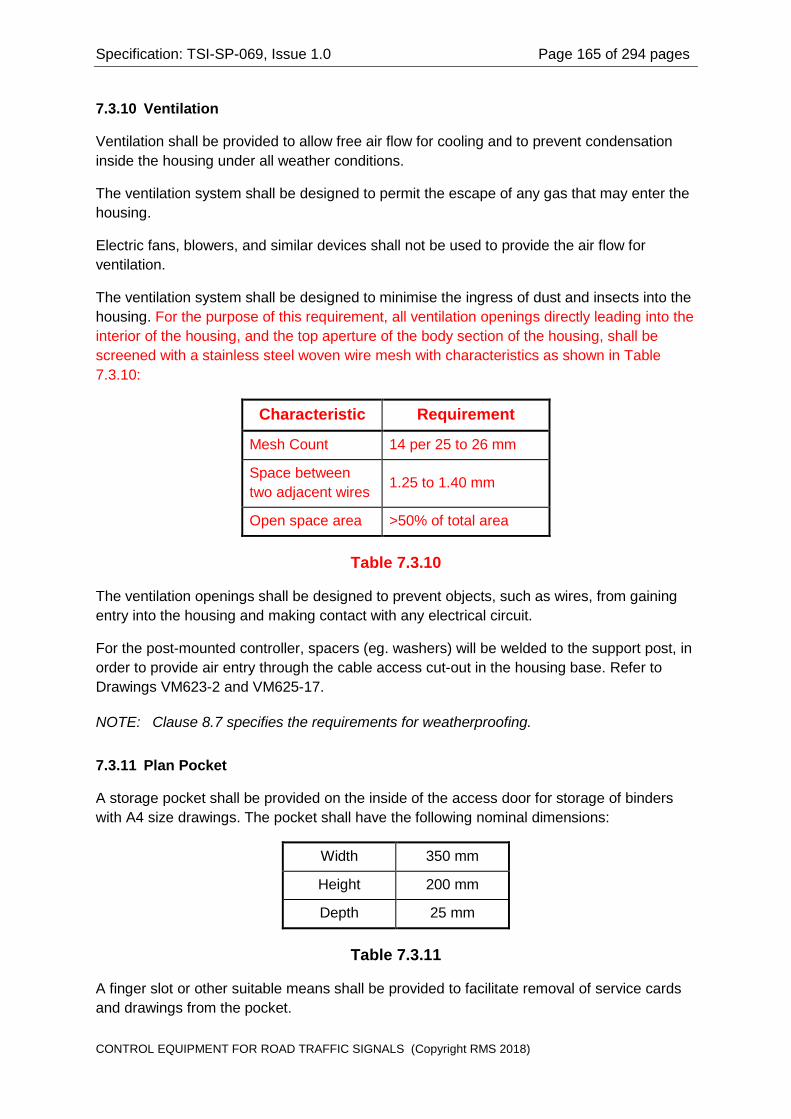
Specification: TSI-SP-069, Issue 1.0 Page 165 of 294 pages
7.3.10 Ventilation
Ventilation shall be provided to allow free air flow for cooling and to prevent condensation inside the housing under all weather conditions.
The ventilation system shall be designed to permit the escape of any gas that may enter the housing.
Electric fans, blowers, and similar devices shall not be used to provide the air flow for ventilation.
The ventilation system shall be designed to minimise the ingress of dust and insects into the housing. For the purpose of this requirement, all ventilation openings directly leading into the interior of the housing, and the top aperture of the body section of the housing, shall be screened with a stainless steel woven wire mesh with characteristics as shown in Table 7.3.10:
Characteristic Requirement
Mesh Count 14 per 25 to 26 mm
Space between two adjacent wires 1.25 to 1.40 mm
Open space area >50% of total area
Table 7.3.10
The ventilation openings shall be designed to prevent objects, such as wires, from gaining entry into the housing and making contact with any electrical circuit.
For the post-mounted controller, spacers (eg. washers) will be welded to the support post, in order to provide air entry through the cable access cut-out in the housing base. Refer to Drawings VM623-2 and VM625-17.
NOTE: Clause 8.7 specifies the requirements for weatherproofing.
7.3.11 Plan Pocket
A storage pocket shall be provided on the inside of the access door for storage of binders with A4 size drawings. The pocket shall have the following nominal dimensions:
Width 350 mm
Height 200 mm
Depth 25 mm
Table 7.3.11
A finger slot or other suitable means shall be provided to facilitate removal of service cards and drawings from the pocket.
CONTROL EQUIPMENT FOR ROAD TRAFFIC SIGNALS (Copyright RMS 2018)

Specification: TSI-SP-069, Issue 1.0 Page 166 of 294 pages
7.3.12 No Longer Used
Section Deleted by Amendment 2
7.3.13 Holder for Hand Held Terminal
A holder, or cradle, shall be provided to support a Hand Held Terminal (HHT) complying with Specification HHT/1.
The holder shall be located in a convenient position to allow use of the HHT without removal from the holder, such as on the inside of the access door.
The mounting position shall also be chosen such that the connecting cable to the HHT will not be damaged, and will not interfere with other equipment in the housing, when the controller access door is opened or closed.
The HHT shall be readily removed from the holder and readily replaced into the holder.
The presence of the HHT in the holder shall not interfere with the normal closing and securing of the access door.
7.3.14 Equipment Shelf
The wired housing shall have a rigid equipment shelf for mounting the Logic Module, the Vehicle Detection System and any other free standing ancillary equipment.
The equipment shelf shall be mounted not less than 390 mm below the top of the door opening.
The front edge of the shelf shall be turned down and shall have a series of holes for securing the wander leads to the Logic Module with cable ties. Refer to drawing VM625-25.
The rear edge of the shelf shall be turned up to provide strength and to position the Logic Module forward of the rear wall of the controller housing. Refer to drawing VM625-25.
7.3.15 Finish and Protection
Both the interior and exterior of the housing (body, roof, base and access door(s)) shall be suitably treated to prevent corrosion.
All exterior surfaces of the housing shall have a durable gloss finish of anti-graffiti polyester powder coating with a minimum thickness of 50 microns.
The surfaces shall be thoroughly cleaned and subject to the appropriate pre-treatment before the powder coating is applied.
The colour of the exterior finish shall be Smoke Blue (Colour No. T33) in accordance with AS 2700.
CONTROL EQUIPMENT FOR ROAD TRAFFIC SIGNALS (Copyright RMS 2018)

Specification: TSI-SP-069, Issue 1.0 Page 167 of 294 pages
NOTE: Overspray is permitted on the interior of the housing, but earthing points must be kept free of paint and other non-conducting surface coating to ensure earthing continuity.
NOTE: Refer to Clause I.2 in Appendix I for a suitable anti-graffiti polyester powder coat material.
7.3.16 Controller Nameplate
A metal nameplate shall be affixed to the exterior of the controller housing.
NOTE: The positioning of the nameplate is related to the positioning of the Facility Switch. Refer to Clause 7.7.
The key access for the Facility Switch shall be via a suitable cut-out in the Controller Nameplate.
The nameplate shall provide the following information:
(a) Manufacturer;
(b) Controller Type, (name and identifying numbers);
(c) Serial Number; and
(d) Facility Switch position indications (Clause 7.7.6).
A high quality process (such as photo engraving, anodising, etc) shall be used to produce the legends on the nameplate. The legends shall be clearly legible, indelible, and non fading.
The nameplate shall be made from aluminium, or a suitable alternative material approved by the Manager. Adhesive labels shall not be used.
NOTE: Notwithstanding the requirements of Clause 7.3.1, a concession will be given for mounting the nameplate on the housing by screws with blind cup heads, or by suitable sealed pop-rivets with smooth low profile heads.
NOTE: Refer to Clause 13.2 regarding a concession for the marking of the housing Serial Number.
7.3.17 Resistance to Vandalism
The controller housing shall be designed to withstand vandalism. As a minimum, particular attention shall be given to the design to preclude the following:
(a) Forcibly opening the access door(s);
(b) Opening the access door(s) by simple tools or implements, such as by screwdrivers or pliers, or similar common tools being used to open the door locks or part the hinges;
(c) Forcibly pushing the controller from its mountings; and
(d) Damage to the housing or door(s) or mounting base by kicking or pushing.
CONTROL EQUIPMENT FOR ROAD TRAFFIC SIGNALS (Copyright RMS 2018)

Specification: TSI-SP-069, Issue 1.0 Page 168 of 294 pages
NOTE: Refer also to Clause 8.9 for additional requirements for vandal resistance.
7.4 Cable Clamping Bars
7.4.1 General
Clamping bars shall be provided for securing and supporting all external cables (other than the telecommunications line). That is, clamping bars shall be provided for:
(a) Consumers Mains;
(b) Signal cables;
(c) Minor Linking cable; and
(d) Detector loop feeder cables.
NOTE: Several clamping bars and clamping points will be necessary to meet the requirements of this clause.
7.4.2 Position
The clamping bars for each group of cables shall be positioned in the immediate vicinity below the respective termination points for the cables.
7.4.3 Clamping Action and Capacity
For the ground-mounted controller, clamping bars shall be provided as specified below.
The method for clamping the cables shall be such that all cables shall be uniformly clamped regardless of the mix of cable types and sizes.
The clamping bar for the Consumers Mains shall accommodate two (2) single double insulated cables with sizes from 6 mm2 to 16 mm2.
The clamping bars for signal cables shall accommodate up to six (6) cables complying with AS 2276.1, with any mix of cable sizes up to 51 cores.
NOTE: The maximum cable diameter is 40 mm and the minimum diameter is 10 mm.
Provision shall be made for clamping a Minor Linking cable, either separately or together with the signal cables. Alternatively, it is permissible for a tie bar to be provided for a Minor Linking cable.
The clamping bars for detector loop feeder cables complying with AS 2276.2 shall accommodate feeder cables for up to 32 detector loops.
NOTE: It is anticipated that video camera detection systems will be used in the future rather than loop detectors. In such case, the clamping bars for detector loop feeder cables may be used as tie bars for the video coaxial cables.
CONTROL EQUIPMENT FOR ROAD TRAFFIC SIGNALS (Copyright RMS 2018)

Specification: TSI-SP-069, Issue 1.0 Page 169 of 294 pages
For the post-mounted controller, it is sufficient to provide tie bars in the vicinity of the cable access hole for securing cables.
7.5 Switchboard
7.5.1 General
The switchboard circuits shall be as specified in drawing VE533-18.
The switchboard and wiring shall strictly comply with all relevant requirements of AS 3000, Wiring Rules.
NOTE: The switchboard may be of a self-contained type with additional Neutral Link(s) and Earth Link, or may be assembled from separate components.
Clauses 7.5.3 through 7.5.17 specify the equipment comprising the switchboard.
7.5.2 Mounting Position
The switchboard shall be mounted in a readily accessible position in the lower part of the housing. With the housing access door open, the main switch, fault current limiter and circuit breakers shall be directly accessible without the need to remove or swing back any panel or any equipment in the housing.
NOTE: If the switchboard has a protective cover, such as provided on commercially available switchboard assemblies, then it is acceptable for the protective cover to be raised to gain access to the main switch and circuit breakers.
The switchboard shall be suitably positioned to be protected from rain, as far as is practicable, when the access door is open.
No part of the switchboard shall be within the space 150 mm above the bottom edge of the housing mounting base.
The switchboard components shall be protected by covers or protective barriers to preclude accidental contact with mains voltage. Refer to Clause 7.24.2.
7.5.3 Main Switch and Fault Current Limiter
The main switch shall control the supply to all circuit breakers comprising the switchboard, but shall not control supply to the fault current limiter.
The main switch shall be rated at not less than 80 A. Alternatively, the main switch may be a circuit breaker with a current rating of 32 A and a breaking capacity not less than 8 kA.
The main switch shall be a circuit breaker with a current rating of 32 A and a breaking capacity not less than 8 kA.
The fault current limiter shall be a fuse with a replaceable cartridge element, rated at 32 A, and shall comply with the requirements of AS 2005.
CONTROL EQUIPMENT FOR ROAD TRAFFIC SIGNALS (Copyright RMS 2018)

Specification: TSI-SP-069, Issue 1.0 Page 170 of 294 pages
The fault current limiter shall be suitably positioned to facilitate connection of the active conductor of the consumers mains.
7.5.4 Lamps Circuit Breaker
The Lamps circuit breaker shall be rated at 20 10A, with a breaking capacity not less than 8 kA, and shall control the supply to all signal lamp circuits.
7.5.5 Flash Circuit Breaker
The Flash circuit breaker shall be rated at 16 10A, with a breaking capacity not less than 8 kA, and shall control the supply to a flasher unit for the Flash mode signal display.
7.5.6 Logic Circuit Breaker
The Logic circuit breaker shall be rated at not greater than 10 A, with a breaking capacity not less than 8 kA, and shall control the supply to the controller electronics (other than the flasher unit).
7.5.7 Detector Circuit Breaker
The Detector circuit breaker shall be rated at not greater than 10 A, with a breaking capacity not less than 8 kA, and shall control the supply to detector equipment.
7.5.8 Auxiliary Circuit Breaker and CCTV Circuit Breaker
The Auxiliary circuit breaker shall be rated at 16 10A, with a breaking capacity not less than 8 kA, and shall control the General Purpose Outlet (GPO) and any auxiliary circuits.
The Auxiliary circuit breaker shall not be a type with an integral residual current circuit breaker.
NOTE: The Auxiliary circuit breaker will control mains supply to external equipment, such as closed circuit television cameras, Red Signal violation cameras, etc. The requirement is that the external equipment is not subject to nuisance tripping of a residual current circuit breaker.
NOTE: Refer to Clause 7.5.12 for requirements for the General Purpose Outlet.
The CCTV circuit breaker shall be rated at 10 A, with a breaking capacity not less than 8 kA, and shall control the supply to external CCTV equipment.
The CCTV circuit breaker shall not be a type with an integral residual current circuit breaker.
7.5.9 Active Bus Bar
A bus bar may be used for connecting the supply active to each of the circuit breakers, providing the bus bar is suitably insulated to prevent risk to personnel.
CONTROL EQUIPMENT FOR ROAD TRAFFIC SIGNALS (Copyright RMS 2018)

Specification: TSI-SP-069, Issue 1.0 Page 171 of 294 pages
7.5.10 Neutral Links
Two Neutral Links (NL1 and NL2) shall be provided in an arrangement to allow the use of an EMI filter for the suppression of EMI.
NOTE: Refer to the switchboard circuit, Drawing VE533-18, for the required circuit arrangement for the Neutral Links.
Neutral Link 1 (NL1) shall be rated at 80 A and shall provide terminals with two (2) screws for the connection of:
(a) MEN Earth (at one extremity);
(b) Consumers Mains neutral (adjacent to MEN Earth);
(c) neutral connection to a surge diverter (Clause 7.5.13); and
(d) supply side neutral connection to the EMI filter (Clause 7.5.14).
Neutral Link 2 (NL2) shall be rated at 80 A and shall provide a terminal with two (2) screws for the load side neutral connection to the EMI filter (Clause 7.5.14). Neutral Link 2 shall be the distribution link for neutral returns for each of the circuits.
The Neutral Links shall be mounted in accessible positions on the front of the switchboard. Notwithstanding, if the switchboard has a removable protective cover then it is acceptable for the protective cover to be removed to gain access to the links.
The Neutral Links shall each be fitted with a removable insulated cover.
The position and order of circuit neutrals connected to Neutral Link 2 shall correspond to the order of the circuit breakers controlling the respective circuits.
Neutral Link 2 shall provide a minimum of three (3) spare termination positions.
7.5.11 Earth Link
The Earth Link shall be rated at 80 A and shall provide terminals with two (2) screws for all connections to the link.
A connection point shall be reserved at one extremity of the link for connection of the Main Earth. The MEN Earth connection shall be made to the terminal adjacent to the Main Earth connection terminal.
The Earth Link shall provide a minimum of three (3) spare termination positions.
The MEN link shall be a stranded earth conductor with a minimum cross-sectional area of 6 mm2.
7.5.12 GPO with Integral Residual Current Device
The switchboard shall be fitted with a double General Purpose Outlet (GPO) with an integral 30 milliampere Type II Residual Current Device, complying with AS 3190.
CONTROL EQUIPMENT FOR ROAD TRAFFIC SIGNALS (Copyright RMS 2018)

Specification: TSI-SP-069, Issue 1.0 Page 172 of 294 pages
The GPO shall be mounted in an accessible position in the housing. Where the GPO is mounted on the switchboard, a barrier shall be provided to segregate the rear of the GPO from the switchboard components and wiring.
NOTE: The GPO may be mounted in a position separate from the switchboard.
The GPO (socket outlet) shall be mounted separate from the switchboard in an accessible position in the housing.
7.5.13 Surge Diverter
The equipment shall be effectively protected against surges on the incoming mains supply, such as surges induced by lightning, switching spikes, and similar transients (refer to Clauses 8.3.2 and 8.3.3).
Where a surge diverter incorporates one or more Metal Oxide Varistor (MOV) devices, it shall include an indicator which shall be lit while the MOV devices are functional, and extinguished when any of the MOV devices has failed.
Where a surge diverter incorporates one or more consumable surge suppression devices, such as Metal Oxide Varistor (MOV) devices, it shall provide the following:
(a) An indicator which shall be lit while the surge suppression devices are functional, and extinguished when any of the surge suppression devices has failed. This indicator shall be clearly visible when the front access door to the controller housing is in the open position;
(b) The surge suppression devices shall be accommodated in a pluggable fire-resistant or fire-retardant container with suitable electrical contacts for connection to the surge diverter;
(c) The removal and insertion of the pluggable container shall not require the controller to be switched off;
(d) The positioning and mounting of consumable surge suppression devices shall facilitate ease of inspection and direct replacement of the devices without hindrance.
If a commercially available surge diverter is used, it may be either a rail-mounted type or a panel-mounted type.
Discrete component surge diverters shall be mounted on terminal blocks provided specifically for this purpose. Surge suppression devices shall not be mounted as "flying lead" devices in any terminal of the main switch or any circuit breaker, and shall be kept clear of all cables.
The position and mounting of consumable surge suppression devices, such as Metal Oxide Varistor (MOV) devices, shall facilitate inspection and replacement of the devices.
The surge diverter shall be effectively isolated from the mains supply when the main switch is in the open position.
CONTROL EQUIPMENT FOR ROAD TRAFFIC SIGNALS (Copyright RMS 2018)

Specification: TSI-SP-069, Issue 1.0 Page 173 of 294 pages
NOTE: The wiring to the surge diverter shall be kept as short as practicable, and shall not have sharp bends. That is, the wiring shall have either no bends, or large radius bends.
NOTE: Metal Oxide Varistor devices shall be mounted in a separate enclosure, or well clear of wiring and other components to minimise damage in the event that the MOV takes fire.
7.5.14 EMI Filter
An EMI filter, with a minimum rating of 32 A, shall be provided, to meet the requirements of Clause 8.6 for suppressing the generation of EMI.
The filter shall be designed to operate effectively with the high surge currents caused by the switching of lamp loads in phase control circuits.
NOTE: It will be necessary for the filter to incorporate air-cored inductors in series with both the active and neutral circuits to meet this requirement.
The EMI filter shall comply with the specifications in Drawing VE533-22.
NOTE: Refer to the Switchboard Circuit, Drawing VE533-18, for the connections to the EMI Filter.
NOTE: Special precautions may be necessary for the connections to the EMI Filter to meet the requirements of Clause 7.24.2.
7.5.15 Spare Panel Space for Auxiliary Switch
Sufficient spare panel space shall be provided on the switchboard to allow the mounting of an Auxiliary Switch. The switch shall be a single pole narrow architrave type, mounted on a block.
The switchboard panel shall be pre drilled to facilitate the mounting of the block and wiring of the switch.
NOTE: There is no requirement to supply either the switch or the mounting block. These will be fitted in the workshop when required.
A melamine terminal block with six terminals shall be provided in an accessible position for termination of wiring to the Auxiliary Switch.
This terminal block shall also be used to provide termination of the Detector Active and Neutral for detector equipment mounted within the controller housing.
Terminal Circuit Connection
TB-1 Auxiliary circuit Active
CONTROL EQUIPMENT FOR ROAD TRAFFIC SIGNALS (Copyright RMS 2018)

Specification: TSI-SP-069, Issue 1.0 Page 174 of 294 pages
TB-2 Auxiliary circuit Neutral
TB-3 Auxiliary circuit Earth
TB-4 Internal detector circuit Active
TB-5 Internal detector circuit Neutral
TB-6 Internal detector circuit Earth
Table 7.5.15
NOTE: Refer to the Switchboard Circuit, Drawing VE533-18, for the connections to the terminal block.
7.5.16 Switchboard Marking
Each component comprising the switchboard shall be clearly and indelibly marked with an appropriate designation to indicate the function.
The Fault Current Limiter shall be clearly labelled as follows:
FAULT CURRENT LIMITER 32A,
NOT CONTROLLED BY MAIN SWITCH.
The EMI Filter shall be clearly labelled, "EMI FILTER", in addition to the markings required by Clause 5.1.3 of Specification ECA/2.
The surge diverter components shall be marked adjacent to the mounting position or beside the associated terminal block with the corresponding circuit reference(s).
Each of the other switchboard components shall be clearly labelled as specified in the following table.
Item Device Marking
1. Main Switch MAIN SWITCH
2. Lamps Circuit Breaker LAMPS 20A 10A
3. Flash Circuit Breaker FLASH 16A 10A
4. Logic Circuit Breaker LOGIC 10A
5. Detector Circuit Breaker DETS 10A
6. Auxiliary Circuit Breaker AUX 16A 10A
CONTROL EQUIPMENT FOR ROAD TRAFFIC SIGNALS (Copyright RMS 2018)

Specification: TSI-SP-069, Issue 1.0 Page 175 of 294 pages
7. Neutral Link 1 NL1
8. Neutral Link 2 NL2
9. Earth Link EL
10. Auxiliary Switch AUX SW
11. Terminal Block TB
12 CCTV Circuit Breaker CCTV 10A
Table 7.5.16
NOTE: If the Main Switch is a Circuit Breaker, then its current rating shall also be appended to the legend, "MAIN SWITCH".
NOTE: If Circuit Breakers rated at less than 10 A are used for the Logic or Detector Circuits then the corresponding label(s) shall be clearly marked with the appropriate current rating rather than 10 A as shown in table 7.5.16.
7.5.17 Order of Switches on the Switchboard
The order of the Circuit Breakers, from left to right as viewed from the front of the switchboard, shall be:
(a) Main Switch;
(b) Lamps Circuit Breaker;
(c) Flash Circuit Breaker;
(d) Logic Circuit Breaker;
(e) Detector Circuit Breaker; and
(f) Auxiliary Circuit Breaker.
(g) CCTV Circuit Breaker.
7.5.18 Spare Space for Additional Circuit Breaker
Sufficient spare space shall be provided on the circuit breaker mounting DIN rail to allow the mounting of a spare circuit breaker to the right of the Auxiliary Circuit Breaker.
Provision shall be made for the labelling of the additional circuit breaker.
7.6 Field Terminal Blocks
7.6.1 Terminal Types
The Field Terminal Blocks provide connection of field wiring to:
(a) Signal Aspects;
(b) Pedestrian Pushbuttons;
CONTROL EQUIPMENT FOR ROAD TRAFFIC SIGNALS (Copyright RMS 2018)

Specification: TSI-SP-069, Issue 1.0 Page 176 of 294 pages
(c) External Vehicle Detectors;
(d) Detector Loops;
(e) Minor Linking connections to other controllers; and
(f) All other external Low Voltage circuits.
The terminals for (a), (b), (c) and (f) above shall be rail-mounted, screw-clamp types with spring-loading. The voltage rating shall be not less than 500 Volts r.m.s. and the continuous current rating shall be not less than 30 A.
The terminals shall be capable of accepting conductors with cross sectional areas from 0.5 mm2 to 4 mm2.
The design of the terminals shall be such as to accept the crimp type lip blade terminal lugs specified in Clause I.3 in Appendix I.
The terminals shall be equivalent to the terminals specified in Clause I.4 in Appendix I.
Flash barriers shall be provided between adjacent Low Voltage (LV) circuits, and between adjacent Low Voltage and Extra Low Voltage (ELV) circuits.
The terminals shall be mounted on rails.
A removable, clip-on transparent cover shall be provided for each of the Field Terminals (a), (b), (c) and (f) above, to prevent accidental contact with live circuits. Refer to Clause 7.24.2. The cover(s) shall have sufficient rigidity to maintain protection while fitted in place, and shall not be easily deformed by heat or environmental effects.
The terminals used for connection of Detector Loop Feeder Cables (d), and the terminals for field wiring for Minor Linking (e), shall have voltage rating not less than 250 Volts r.m.s. and shall have continuous current rating not less than 10 A. The terminals shall be capable of accepting conductors with cross sectional areas from 0.5 mm2 to 2.5 mm2.
Terminals which solder to printed circuit board assemblies shall be of a type which does not place stress on the soldered joints when the screw connections are being secured.
For the ground-mounted controller, the terminal block layout, assembly and numbering shall be in accordance with Drawings VM625-21 and VM625-22. Terminal blocks shall be conveniently accessible in the housing and shall not be less than 300 mm above the base of the housing.
For the post-mounted controller, the terminal block layout, assembly and numbering shall be in accordance with Drawings VM625-17 and VM625-18. A rear door may be provided to facilitate access to the terminal blocks.
7.6.2 Signal Circuits
Three termination points shall be provided for connection of external cables for each aspect of each signal group.
CONTROL EQUIPMENT FOR ROAD TRAFFIC SIGNALS (Copyright RMS 2018)

Specification: TSI-SP-069, Issue 1.0 Page 177 of 294 pages
For the ground-mounted controller, terminal blocks shall be fitted for twelve (12) signal groups, ie terminal block assemblies A, B and C in Drawings VM625-21 and VM625-22.
For the ground-mounted controller, mounting points and any necessary fittings shall be provided to allow the D terminal block assembly to be readily fitted in the field or in the workshop. That is, provision shall be made to allow the terminations to be readily expanded up to sixteen (16) signal groups.
For the ground-mounted controller, mounting points shall be provided to allow the AA, BB, CC and DD terminal blocks to be fitted in the workshop. That is, provision shall be made to allow the terminations to be expanded up to thirty-two (32) signal groups.
For the post-mounted controller, terminal blocks shall be provided for six (6) signal groups, as specified by Drawings VM625-17 and VM625-18.
The arrangement shall make provision for the post-mounted housing to be modified in the workshop to provide terminations for eight (8) signal groups.
7.6.3 Lamp Active and Neutral
Terminals shall be provided for connection of external cables to the Lamp Active and Lamp Neutral circuits.
For the ground-mounted controller, two (2) termination points shall be provided for the Lamp Active and four (4) termination points shall be provided for the Lamp Neutral at each of the terminal block assemblies A, B, C and D, for signal group circuits. Refer to Drawing VM625-22.
The Lamp Active at Terminals A2, B2, C2 and D2 shall not be subject to dimming. There is no requirement for the Lamp Active at these terminals to be regulated. Refer to Clause 7.22 for cabling requirements.
NOTE: There is no requirement for terminals to be provided for Lamp Active or Lamp Neutral on the AA, BB, CC, or DD terminal block assemblies.
For the post-mounted controller, three (3) termination points shall be provided for the Lamp Active and seven (7) termination points shall be provided for the Lamp Neutral at the terminal block assembly A for signal group circuits. Refer to Drawing VM625-18.
7.6.4 Detector Active and Neutral
For the ground-mounted controller, seven (7) and three (3) termination points respectively shall be provided for connection of external cables to the Detector Active and Detector Neutral circuits (ie for external detector units). Refer to Drawing VM625-22.
For the post-mounted controller, three (3) termination points shall be provided for connection of external cables to each of the Detector Active and Detector Neutral circuits (ie for external detector units). Refer to Drawing VM625-18.
CONTROL EQUIPMENT FOR ROAD TRAFFIC SIGNALS (Copyright RMS 2018)

Specification: TSI-SP-069, Issue 1.0 Page 178 of 294 pages
7.6.5 External Detector Inputs and Detector Common
For the ground-mounted controller, three (3) termination points shall be provided for connection of external cables for each of sixteen (16) external inputs (ie external detector and/or pushbutton inputs 1 16).
For the ground-mounted controller, provision shall be made for mounting terminals for a further sixteen (16) inputs. A single termination point is required at each of the terminals for external inputs 17 32.
NOTE: There is no requirement to provide terminals for external inputs 17 32. These will be added in the workshop when required.
For the ground-mounted controller, seven (7) terminations shall be provided for each of terminals E3 and E4 on the E terminal block assembly (Drawings VM625-21 and VM625-22) for connection of detector and pushbutton common returns (and Wait indicator returns).
For the post-mounted controller, three (3) termination points shall be provided for connection of external cables for each of twelve (12) external inputs (ie external detector and/or pushbutton inputs 1 12). Refer to Drawing VM625-18.
For the post-mounted controller, five (5) terminations shall be provided for connection of detector and pushbutton common returns.
7.6.6 Minor Linking
For the ground-mounted controller, provision shall be made for mounting a melamine terminal block, or a terminal block assembly, for connection of twelve (12) cores of a Minor Linking cable. A single termination point is required for each core of the linking cable.
NOTE: There is no requirement to provide the terminals for Minor Linking. These will be fitted in the workshop when required.
7.6.7 Loop Terminations
Terminal blocks shall be provided for connecting Loop Feeder Cables (complying with AS 2276.2) for detector units mounted inside the housing. A single terminal is required for each loop feeder cable connection, ie two (2) terminals per detector loop.
A bar or link shall be provided for earthing the screens of loop feeder cables. The earthing bar or link shall be connected to the Earth Link on the switchboard.
Each termination point on the bar or link shall be provided with two (2) screws.
For ground-mounted housings with terminals for sixteen (16) signal groups or less, terminals shall be provided for connection of feeder cables for sixteen (16) detector loops. For ground-mounted housings with terminals for more than sixteen (16) signal groups, terminals shall be provided for connection of feeder cables for thirty two (32) detector loops. For all ground-mounted housings, the link for earthing cable screens shall provide a minimum of five (5) available termination points.
CONTROL EQUIPMENT FOR ROAD TRAFFIC SIGNALS (Copyright RMS 2018)

Specification: TSI-SP-069, Issue 1.0 Page 179 of 294 pages
For the post-mounted housing, terminals shall be provided for connection of loop feeder cables to twelve (12) detector loops. The link for earthing cable screens shall provide a minimum of five (5) available termination points.
7.7 Facility Switch
7.7.1 Standard Key
The Facility Switch shall provide for the signal displays to be switched to the ON, OFF and FLASH modes, by means of a key complying with Drawing VM005-1.
The key access shall be provided from the exterior of the controller housing, without the need to open the housing access door.
7.7.2 Switch Positions and Function
The Facility Switch shall provide three (3) positions, in clockwise order:
(a) OFF
(b) FLASH
(c) ON
The OFF position shall remove Low Voltage from all external circuits deriving supply from within the controller housing. That is, Low Voltage shall be removed from all signal circuits, from external detector equipment, and from audio-tactile driver equipment. Provision shall also be made to remove the Low Voltage supply from external auxiliary circuits. The OFF position shall also disable the flashing active outputs from the Flasher Unit. These functions shall not be dependent upon the controller logic circuits.
NOTE: The Low Voltage supply for audio-tactile driver equipment is sourced from the (unregulated, undimmed) Lamp Active supply at the A, B, C or D terminal block assemblies.
The FLASH position shall place the signals in the Flash mode. In this mode the Flash Change-over Relays (Clause 7.9) shall be energised and the Flasher output (Clause 7.12) shall be applied to the Yellow aspect of designated signal groups. This function shall not be dependent upon the controller logic circuits.
The FLASH position shall remove the Lamp Active supply from the signal switching circuits and audio-tactile driver equipment, but shall not remove the Low Voltage supply from external detector equipment or from external auxiliary circuits.
The ON position, (and Manual and Step positions if provided), shall allow the controller logic to operate the signals with normal displays. The Low Voltage supply shall be available to external detector equipment, audio tactile driver equipment and auxiliary circuits for normal operation.
CONTROL EQUIPMENT FOR ROAD TRAFFIC SIGNALS (Copyright RMS 2018)

Specification: TSI-SP-069, Issue 1.0 Page 180 of 294 pages
The Low Voltage supply to the controller logic and to detector units mounted inside the controller housing shall not be interrupted by the Facility Switch in any of its positions.
A contact shall be provided on the Facility Switch to interrupt the drive to the Master Relay (Clause 7.8) when the Facility Switch is in the Off and Flash positions.
A contact shall be provided on the Facility Switch to interrupt the drive to the Auxiliary Relay (Clause 7.8) when the Facility Switch is in the Off position.
A contact shall be provided on the Facility Switch to disable the Flashing Active outputs on the Flasher Unit.
The Facility Switch shall provide contacts to allow the controller logic circuits to sense the position of the Facility Switch. The switch position shall be encoded using the Gray code specified in Table 7.7.2a.
Switch Position
Gray Code
Contact A Contact B
Off 1 0
Flash 1 1
On 0 1
Table 7.7.2a
In Tables 7.7.2a above, a "1" shall correspond to the contact being closed, and a "0" shall correspond to the contact being open.
7.7.3 Type and Rating
The Facility Switch shall be an industrial grade switch suitable for use in outdoor equipment.
The Facility Switch shall not be used to switch Low Voltage.
The Facility Switch contacts shall be rated for switching Extra-Low Voltage control signals, operating at voltages of nominally 12 V d.c., and currents of 1 to 10 mA.
The contact material and rating for the contacts shall be suitably chosen to provide reliable operation for the life of the equipment in the environment specified in Clauses 8.1 and 8.2.
7.7.4 Mounting
The Facility Switch shall be mounted inside the controller housing in close proximity to the controller nameplate.
CONTROL EQUIPMENT FOR ROAD TRAFFIC SIGNALS (Copyright RMS 2018)

Specification: TSI-SP-069, Issue 1.0 Page 181 of 294 pages
The key actuator for the Facility Switch shall be recessed inside a metal ferrule, such that the head of the actuator is recessed 10 mm to 12 mm from the outside surface of the controller housing.
The method of mounting the Facility Switch shall be such that the switch can be readily replaced in the field. Special tools shall not be required to replace the Facility Switch.
For the ground-mounted controller, the Facility Switch shall be mounted within 250 mm of the top of the housing, on either the left or right side of the housing. The Facility Switch shall not be mounted on the rear side of the housing or the controller access door.
For the post-mounted controller, the Facility Switch shall be mounted on the front face of the housing below the access door. Refer to Drawing VM625-17.
7.7.5 Weatherproofing
The key access for the Facility Switch shall be suitably weatherproofed to provide the degree of protection specified in Clause 8.7.
7.7.6 Marking
The switch positions shall be indelibly and durably marked on the controller nameplate affixed to the outside of the housing (Clause 7.3.16). The switch positions shall be marked in clockwise order:
(a) OFF
(b) FLASH
(c) ON
The acute angle of the switch actuator shall indicate the current switch position.
7.7.7 Resistance to Vandalism
The actuator mechanism for the Facility Switch shall provide sufficient spring tension that the switch position cannot be changed without the use of the specified key. That is, it shall not be possible to change the switch position with simple tools or implements, such as screwdrivers, pliers, etc.
7.7.8 Connection to the Site Identification Card (Connector ZSW)
The wiring to the Facility Switch contacts shall be terminated in a female connector which shall mate with the corresponding header connector (ZSW) on the Site Identification Card.
The pin connections for connector ZSW shall be as specified in Table G.1.8 in Appendix G.
NOTE: For connections between the housing wiring and the Facility Switch, refer to Drawing VE533-17.
CONTROL EQUIPMENT FOR ROAD TRAFFIC SIGNALS (Copyright RMS 2018)

Specification: TSI-SP-069, Issue 1.0 Page 182 of 294 pages
NOTE: The specification for the Site Identification Card makes provision for an electronic device with a serial data output to be used for the Facility Switch in place of a mechanical switch. An amendment will be made to this specification in the future to specify the electronic device.
7.8 Master Relay and Auxiliary Relay
7.8.1 Function
The Master Relay shall provide the means for the logic circuits and the Facility Switch to control the Low Voltage supply to the signal group circuits (including the Lamp Active supply at terminals A2, B2, C2 and D2 on the A, B, C and D terminal block assemblies).
The Auxiliary Relay shall provide the means for the logic circuits and the Facility Switch to control the Low Voltage supply to equipment external to the controller housing.
The coil drive for both the Master Relay and the Auxiliary Relay shall be derived from the power supply in the Logic Module. Both contactors shall thus be controlled by the Logic Circuit Breaker on the switchboard.
7.8.2 Type and Rating
The coil for each contactor shall be rated for operation from a nominal 24 V d.c. supply. The maximum operating current shall not exceed 200 mA at 24 V d.c.
The Master Relay and the Auxiliary Relay shall each be a heavy duty contactor with a minimum of two (2) load switching contacts and one control contact.
The load switching contacts shall be rated for loads of 20 A, AC 2 service.
The control contacts shall be rated for switching Extra-Low Voltage control signals, operating at voltages of nominally 12 V d.c., and currents of 1 to 10 mA.
The contact material and rating for the contacts shall be suitably chosen to provide reliable operation for the life of the equipment in the environment specified in Clauses 8.1 and 8.2.
The contactors shall be a type with a minimum breakdown voltage of 3,000 volts r.m.s. across open contact sets, between contacts sets, between contact sets and coil, and between contact sets and frame.
Each contactor shall be of a type which permits visual indication of the current operating state (ie operated or released).
7.8.3 Mounting, Visibility and Accessibility
The contactors shall be mounted with the switching contacts in a vertical plane.
Each contactor shall be mounted in a readily accessible position inside the housing.
CONTROL EQUIPMENT FOR ROAD TRAFFIC SIGNALS (Copyright RMS 2018)

Specification: TSI-SP-069, Issue 1.0 Page 183 of 294 pages
The method of mounting shall be such that each contactor can be readily replaced in the field, without the need for special tools or equipment.
The current operating state of each contactor shall be readily visible when the front access door to the housing is in the open position, without the need to remove or swing back any panel or equipment.
7.8.4 Connection to the Site Identification Card (Connector ZMR)
The wiring to the coil and control contact for both the Master Relay and the Auxiliary Relay shall be terminated in a female connector which shall mate with the corresponding header connector (ZMR) on the Site Identification Card.
The pin connections for connector ZMR shall be as specified in Table G.1.6 in Appendix G.
NOTE: For connections between the housing wiring and the contactors, refer to Drawing VE533-17.
7.9 Flash Change-over Relays and Flash Circuit Protection
7.9.1 Function
The Flash Change over Relays provide the means for switching the Flasher output (Clause 7.12.3) to the Yellow aspect of designated signal groups, and disconnecting the normal signal drives from those aspects.
For each signal group that may operate in the Flash Mode, protection shall be provided to its Flash circuit as described in Clause 7.9.2.
The Yellow aspects shall be driven by the normal signal drive outputs while the Flash Change-over Relays are released (de energised) and shall be driven by the Flasher outputs while the Flash Change-over Relays are operated.
The Flash Change over Relays shall be released while the controller is in normal service.
The Flash Change over Relays shall be energised when the signal displays are in the Flash Mode.
The Flash Change over Relays shall be driven from the Flash Change-over Relay Drive output on the Flasher unit. Refer to Clause 7.12.8.
NOTE: The Facility Switch shall control the Flash Change over Relays indirectly via the Master Relay. The Master Relay shall be released when the Facility Switch is in the Flash and Off positions, thus removing the Lamp Active supply. The Flasher unit shall sense the absence of the Lamp Active supply and activate the Flash Change over Relays, subject to the absence of the Flash Disable signal from the controller logic circuits and the absence of the Disable Flasher signal from the Facility Switch (Off position).
CONTROL EQUIPMENT FOR ROAD TRAFFIC SIGNALS (Copyright RMS 2018)
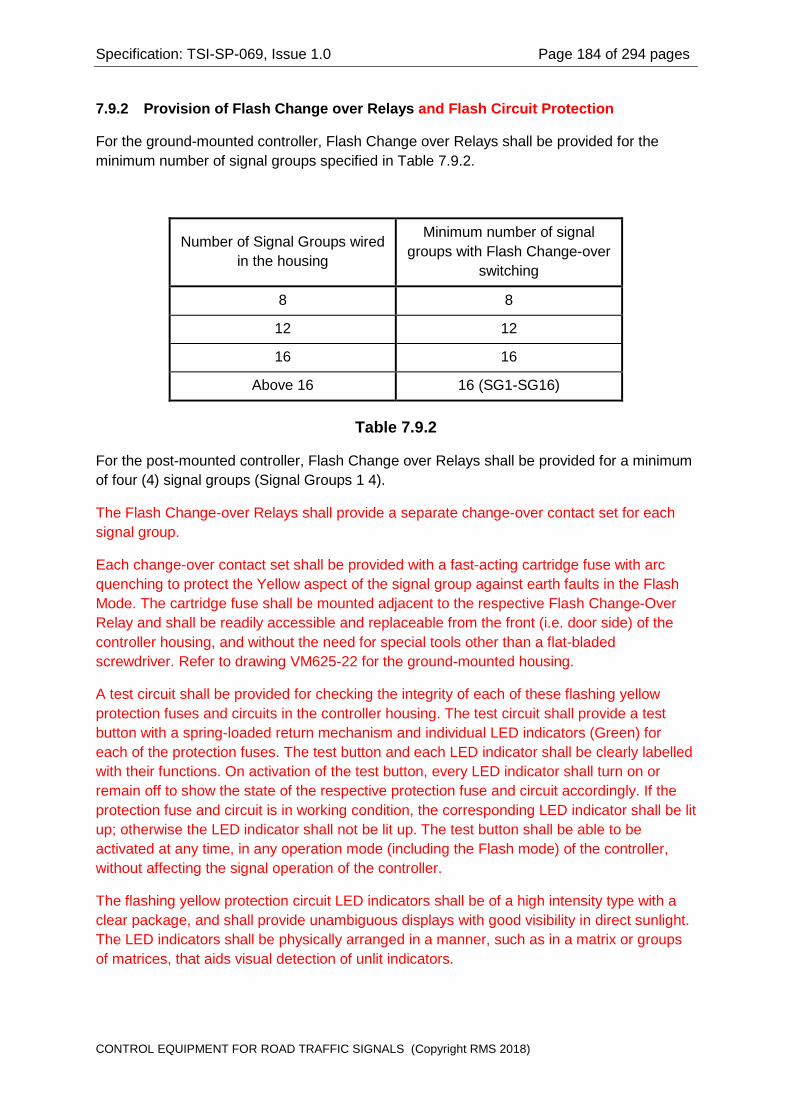
Specification: TSI-SP-069, Issue 1.0 Page 184 of 294 pages
7.9.2 Provision of Flash Change over Relays and Flash Circuit Protection
For the ground-mounted controller, Flash Change over Relays shall be provided for the minimum number of signal groups specified in Table 7.9.2.
Number of Signal Groups wired in the housing
Minimum number of signal groups with Flash Change-over
switching
8 8
12 12
16 16
Above 16 16 (SG1-SG16)
Table 7.9.2
For the post-mounted controller, Flash Change over Relays shall be provided for a minimum of four (4) signal groups (Signal Groups 1 4).
The Flash Change-over Relays shall provide a separate change-over contact set for each signal group.
Each change-over contact set shall be provided with a fast-acting cartridge fuse with arc quenching to protect the Yellow aspect of the signal group against earth faults in the Flash Mode. The cartridge fuse shall be mounted adjacent to the respective Flash Change-Over Relay and shall be readily accessible and replaceable from the front (i.e. door side) of the controller housing, and without the need for special tools other than a flat-bladed screwdriver. Refer to drawing VM625-22 for the ground-mounted housing.
A test circuit shall be provided for checking the integrity of each of these flashing yellow protection fuses and circuits in the controller housing. The test circuit shall provide a test button with a spring-loaded return mechanism and individual LED indicators (Green) for each of the protection fuses. The test button and each LED indicator shall be clearly labelled with their functions. On activation of the test button, every LED indicator shall turn on or remain off to show the state of the respective protection fuse and circuit accordingly. If the protection fuse and circuit is in working condition, the corresponding LED indicator shall be lit up; otherwise the LED indicator shall not be lit up. The test button shall be able to be activated at any time, in any operation mode (including the Flash mode) of the controller, without affecting the signal operation of the controller.
The flashing yellow protection circuit LED indicators shall be of a high intensity type with a clear package, and shall provide unambiguous displays with good visibility in direct sunlight. The LED indicators shall be physically arranged in a manner, such as in a matrix or groups of matrices, that aids visual detection of unlit indicators.
CONTROL EQUIPMENT FOR ROAD TRAFFIC SIGNALS (Copyright RMS 2018)

Specification: TSI-SP-069, Issue 1.0 Page 185 of 294 pages
7.9.3 Flash Change over Relay Type and Ratings
Where more than one Flash Change over Relay is required by Clause 7.9.2, all of the Flash Change over Relays shall be of the same type.
The Flash Change over Relays shall be plug-in heavy duty relays or contactors with the following characteristics:
(a) The coils shall be rated for nominal 24 V d.c. operation;
(b) The maximum coil operating power shall not exceed 3.0 W (125 mA at 24 V d.c.);
(c) Each relay shall provide the equivalent of four (4) heavy duty change over contact sets, ie 4 changeover, or 4 normally open and 4 normally closed;
(d) The contact material for all contact sets shall be silver-cadmium-oxide, or fine silver;
(e) Each contact set shall be rated for switching the nominal mains supply voltage;
(f) Each contact set shall be rated for a minimum of 100,000 operations when switching a load current of 5 A, AC 2 service at the nominal mains voltage;
(g) The relays shall have a minimum breakdown voltage of 2,000 volts r.m.s. across open contact sets, between contacts sets, between contact sets and coil, and between contact sets and frame;
(h) The relays shall have a mechanical life rating exceeding 100,000 operations.
The relays or contactors shall be of a type which permits visual indication of the current operating state (ie operated or released).
7.9.4 Mounting, Visibility and Accessibility
The contactors shall be mounted with the switching contacts in a vertical plane.
Each contactor shall be mounted in an accessible position.
The method of mounting shall be such that a contactor can be readily replaced in the field, without the need for special tools or equipment.
The current operating state of each contactor shall be readily visible when the front access door to the housing is in the open position, without the need to remove or swing back any panel or equipment.
7.9.5 Selection of Signal Groups for Flashing Yellow
Enabling or disabling specific Yellow aspects for connection to the Flasher outputs shall be achieved by changing the position of links on one or more terminal blocks provided for this purpose.
CONTROL EQUIPMENT FOR ROAD TRAFFIC SIGNALS (Copyright RMS 2018)

Specification: TSI-SP-069, Issue 1.0 Page 186 of 294 pages
The wiring to each terminal block shall be colour coded and marked in such a way that there will not be any confusion in enabling or disabling the Flashing Yellow facility for particular signal groups.
The housing shall be supplied with the links wired to enable Flashing Yellow on the minimum number of signal groups specified in Table 7.9.2.
NOTE: Where contactors are used for the Flash Change over Relays, it is permissible to use links wired to the contactor terminals for the enabling of the Flashing Yellow facility for signal groups.
7.10 Lamp Monitor Relay
7.10.1 Function
A Lamp Monitor Relay shall be used to sense the normal operating state of the signal displays for controllers operating with Minor Linking.
The Lamp Monitor Relay shall be used to isolate the Minor Linking output signals from the controller when the signal displays are not in normal operation.
The controller logic is required to sense the state of the signal displays for reporting the lamp status to the SCATS master. It shall not be necessary to provide a Lamp Monitor Relay for this function. The logic circuits are required to constantly monitor and regulate the lamp supply voltage and shall perform the function of sensing the presence of the Lamp Active supply.
7.10.2 Type and Rating
The Lamp Monitor Relay shall be a plug-in relay with a coil rated for mains voltage operation and with two (2) normally open contacts rated at not less than 5 A, AC 2 service.
NOTE: Particular attention should be given to choosing a relay which will give a reliable indication of the signal display state when the mains supply voltage is at the low mains threshold (Clause 8.3.1), over the temperature range specified in Clause 8.1.
The controller documentation for the housing (Section 9) shall provide details of the particular relay type.
7.10.3 Mounting, Visibility and Accessibility
Provision shall be made for mounting the Lamp Monitor Relay in an accessible position in the housing.
The state of the Lamp Monitor Relay shall be readily visible when the front access door is open, without the need to remove or swing back any panel or equipment.
NOTE: The Lamp Monitor Relay is not required to be fitted, except when the controller is operating with Minor Linking. In such case the Lamp Monitor Relay will be fitted in the workshop or in the field.
CONTROL EQUIPMENT FOR ROAD TRAFFIC SIGNALS (Copyright RMS 2018)

Specification: TSI-SP-069, Issue 1.0 Page 187 of 294 pages
7.11 Miscellaneous Relays and Contactors
7.11.1 Function
Provision shall be made for relays to switch Low Voltage to a Daily Event circuit and to three (3) high security Special Facility circuits.
The controller logic Daily Event output shall control the Daily Event Relay(s). Refer to Clause 6.5.12.
The high security Special Facility outputs 1 through 3 shall control the three (3) Special Facility Relays or Contactors. Refer to Clause 6.5.13.2.
NOTE: For the post-mounted housing, there is no requirement for provision of mounting for relays to control Special Facility circuits.
7.11.2 Type and Rating
The Daily Event Relay(s) and the Special Facility Relays shall be a suitable plug-in relay type with four (4) heavy duty change over contact sets.
Each contact set shall be rated at not less than 5 A, AC 2 service.
Each relay coil shall be rated for 24 V d.c. nominal operating voltage and shall have a minimum resistance of 300 ohms.
The relays shall be of a type which provides a visual indication of the current operating state of the relay.
The controller documentation for the housing (Section 9) shall provide details of the particular relay type.
7.11.3 Mounting, Visibility and Accessibility
Provision shall be made for mounting the Daily Event Relay and the Special Facility Relays in accessible positions in the housing.
The state of the Daily Event Relay and Special Facility Relays shall be readily visible when the front access door is open, without the need to remove or swing back any panel or equipment.
NOTE: There is no requirement for the relays to be supplied.
7.12 Flasher Unit
7.12.1 Function and Connections
The Flasher unit shall provide the flashing active supply for the Flash mode of operation for the signal displays.
CONTROL EQUIPMENT FOR ROAD TRAFFIC SIGNALS (Copyright RMS 2018)

Specification: TSI-SP-069, Issue 1.0 Page 188 of 294 pages
The Flasher unit shall be a self-contained unit which connects to the housing wiring circuits by means of plug and socket connectors.
The Flasher unit shall use solid state components exclusively for its circuits and operation.
The Flasher unit shall provide the following inputs:
(a) Flasher mains active supply (Clause 7.12.2);
(b) Lamp Active sensing input; (Clause 7.12.5);
(c) Two inputs for disabling flashing (Clause 7.12.6);
(d) Mains neutral;
(e) Protective Earth.
The Flasher unit shall provide the following outputs:
(a) Two Flashing Active outputs (Clause 7.12.3);
(b) An output to switch the Flash Change over Relays (Clause 7.12.8);
(c) A status output to indicate the state of the Flash Change over Relays (Clause 7.12.9);
(d) An output to indicate that a residual direct current fault has been detected on one or both of the Flashing Active outputs (Clause 7.12.4).
The Flasher shall operate independently of the controller logic circuits. It is a basic requirement that the signals can be operated in the Flash mode with the Logic Module disconnected and removed from the controller housing.
NOTE: Drawing VE533-16 provides a functional block diagram of the Flasher unit. Drawing VE533-17 details the connections for the housing wiring between the Site Identification Encoder and the Flasher unit. Refer to Drawings VE533-18 and VE533-19 for details of the housing Low Voltage wiring connections to the Flasher unit.
7.12.2 Mains Active Supply to the Flasher Unit
The mains active supply to the Flasher unit shall be controlled by the Flash Circuit Breaker on the switchboard.
The mains active supply shall be provided with EMI filtering internal to the Flasher unit, in accordance with Clause 8.6, to prevent electromagnetic interference from being propagated into the mains supply.
NOTE: Particular care is required to prevent radiation from any switchmode power supply circuits in the Flasher unit from coupling into the wiring in the housing.
CONTROL EQUIPMENT FOR ROAD TRAFFIC SIGNALS (Copyright RMS 2018)

Specification: TSI-SP-069, Issue 1.0 Page 189 of 294 pages
7.12.3 Flasher Unit Flashing Active Outputs
The Flasher unit shall provide two Flashing Active output circuits, with each output circuit rated for flashing a 10 A lamp load at a nominal rate of one flash per second.
The flash rate shall be within the range 55 to 65 flashes per minute.
The duty cycle for the outputs shall be selected by jumpers to provide a duty cycle of either:
(a) 40% on and 60% off; or
(b) 50% on and 50% off.
The Flashing Active outputs shall operate in anti-phase such that only one output circuit is supplying power at any time.
The Flasher unit shall provide reliable operation for load power factors of 0.75 and higher.
Each of the Flashing Active outputs shall have a snubber network (ie series connected resistor and capacitor) provided internal to the Flasher unit to prevent spurious turn on of the output TRIACs or SCRs by dV/dt effects.
NOTE: The capacitors in the snubber circuits should preferably be a type with metallised paper dielectric, rated for continuous operation at 250 V r.m.s. or greater.
NOTE: There is no requirement for the Flasher unit to provide either voltage regulation or dimming for the Flashing Active outputs.
The Flashing Active outputs shall be alternately wired to the Flash Change-over Relays to provide the flashing active supply to alternate groupings of four (4) signal groups. Refer to Drawing VE533-19.
7.12.4 Prevention of Residual Direct Current to the Load
The Flasher unit shall be designed to supply power to the load from integral numbers of complete mains cycles (ie, an even number of mains half-cycles).
The Flasher unit shall automatically switch off both Flashing Active output circuits when there is a residual direct current greater than 50 mA in either of the output circuits for 5 seconds or more (such as when an output circuit half waves or fails to trigger reliably with an inductive load).
NOTE: As an alternative for sensing residual direct current in the load, the Flasher unit shall respond to a d.c. voltage greater than 50 volts, averaged across the load for 5 seconds or more.
When a residual direct current is detected, the Flasher unit shall switch the Flashing Active outputs off, release the Flash Change-over Relays, light a Fault LED indicator and remain in this state until the mains supply to the Flasher unit is removed.
CONTROL EQUIPMENT FOR ROAD TRAFFIC SIGNALS (Copyright RMS 2018)

Specification: TSI-SP-069, Issue 1.0 Page 190 of 294 pages
The Fault LED indicator shall have a clear package and shall provide an unambiguous indication in bright sunlight. The display indication shall be Red when lit.
The Flasher unit shall provide an isolated (eg. opto-isolated) output to the controller logic circuits to indicate that a residual direct current fault has occurred.
The Residual Direct Current Fault output shall conform to the following requirements:
(a) In the active state, the output shall sink 5 mA d.c. to the isolated logic common, with a stand-off voltage less than 0.5 V d.c.;
(b) In the inactive state, the output shall have a leakage current less than 0.5 mA d.c. to the isolated logic common with an applied voltage of 15 V d.c.;
(c) The output shall not be damaged by an applied voltage of 15 V d.c. with a source impedance of 1 kilohm or greater;
(d) The output shall provide isolation from the Low Voltage circuits in the Flasher unit with a breakdown voltage not less than 3,000 V r.m.s..
The Residual Direct Current Fault output shall be active when a residual direct current fault has been detected.
7.12.5 Lamp Active Sensing Input
The Flasher unit shall provide an input for sensing the presence of the Lamp Active supply to the signal displays.
The Flasher unit shall provide an interlock such that the Flashing displays cannot be enabled simultaneously with normal signal displays, ie while the Lamp Active Sensing input is active.
The Lamp Active Sensing circuit shall interface mains voltage at the input to the Flasher unit control logic. The Flasher unit shall not be damaged or operate incorrectly with mains voltage present at the Lamp Active Sensing input and no Mains Active Supply to the Flasher unit, (such as when the Flash Circuit Breaker is Off).
The Flasher unit shall be designed to prevent Low Voltage, (ie mains voltage), from the Flasher unit circuits from being applied to the Lamp Active supply to the signal displays. This requirement shall be met regardless of any failure mode of the Flasher unit.
7.12.6 Disable Flash Inputs
The Flasher unit shall provide an isolated (eg. opto-isolated) input driven from the controller logic circuits, as follows:
(a) The input shall be active when the input current exceeds 5 mA d.c.;
(b) The input shall be inactive when the input current is less than 0.5 mA d.c.;
(c) The input standoff voltage shall not exceed 2.5 V d.c. with an input current of 10 mA d.c..
CONTROL EQUIPMENT FOR ROAD TRAFFIC SIGNALS (Copyright RMS 2018)

Specification: TSI-SP-069, Issue 1.0 Page 191 of 294 pages
The Flasher unit shall de-activate the Flash Change over Relay drive output when the Disable Flash input toggles between the inactive and active states at a rate not less than 2 Hz. Refer to Clause 7.12.8.
The Flasher unit shall provide a second isolated input for disabling the Flashing Active outputs when the Facility Switch is in the OFF position. A logic ground at the input shall disable the Flashing Active outputs. The input interface circuit shall not present a voltage greater than 24 V with respect to logic ground at the input terminal.
7.12.7 Flasher Unit Mains Supply Operating Voltage Range
The Flasher unit shall operate correctly and reliably for all incoming mains supply voltages in the range 65% to 120% of the nominal mains supply voltage. Refer to Clause 8.3.1.
The Flasher unit shall de-activate the Flash Change over Relay drive output when the mains supply voltage is too low to provide reliable triggering of the Flashing Active outputs. Refer to Clause 7.12.8.
7.12.8 Flash Change-over Relay Drive Output
The Flasher unit shall provide an output to drive the coils of up to four (4) Flash Change-over Relays (Clause 7.9).
The Flash Change over Relay drive output shall conform to the following requirements:
(a) In the active state the output shall switch a 24 V d.c. voltage to the coils and shall provide a current switching capability of 0.5 A or greater;
(b) In the inactive state the output leakage current, (including snubber circuit), shall be less than 0.1 mA;
(c) The output shall be referenced to the mains neutral for the Flasher unit;
(d) The output shall not be damaged by transients on the mains supply voltage, as specified in Clause 8.3.2.
The Flash Change over Relay drive output shall be provided with a snubber network internal to the Flasher unit to quench back-emf from the Flash Change over Relay coils when the relays are de energised.
The Flash Change over Relay drive output shall be inactive when there is no supply voltage to the Mains Active Supply input to the Flasher unit, such as when the Flash Circuit Breaker is Off.
7.12.9 Flash Change-over Relay Status Output
The Flasher unit shall provide an electrically isolated, (eg. opto-isolated), output to the controller logic circuits to indicate the state of the Flash Change over Relays, (ie operated or released).
CONTROL EQUIPMENT FOR ROAD TRAFFIC SIGNALS (Copyright RMS 2018)

Specification: TSI-SP-069, Issue 1.0 Page 192 of 294 pages
This output shall allow the controller logic to detect the possibility of Flashing Yellow displays together with normal signal displays. Refer to Clauses 6.5.9.3 and 6.8.7.
The output shall also indicate to the controller logic circuits whether the signal displays are Off or in Flash mode when the Lamp Active is not present.
The Flash Change over Relay Status output shall conform to the following requirements:
(a) In the active state, the output shall sink 5 mA d.c. to the isolated logic common, with a stand-off voltage less than 0.5 V d.c.;
(b) In the inactive state, the output shall have a leakage current less than 0.5 mA d.c. to the isolated logic common with an applied voltage of 15 V d.c.;
(c) The output shall not be damaged by an applied voltage of 15 V d.c. with a source impedance of 1 kilohm or greater;
(d) The output shall provide isolation from the Low Voltage circuits in the Flasher unit with a breakdown voltage not less than 3,000 V r.m.s..
The Flash Change over Relay Status output shall be active when the Flash Change over Relay drive output is active, and shall be inactive when the Flash Change-over Relay Drive output is inactive.
The Flash Change over Relay Status output shall be inactive when there is no supply voltage to the Mains Active Supply input to the Flasher unit, such as when the Flash circuit breaker is off.
7.12.10 Flasher Unit Control Logic
The Flasher unit control logic shall energise the Flash Change over Relays and activate the Flashing Active outputs when all of the following conditions are satisfied:
(a) The incoming mains supply voltage at the Mains Active Supply input to the Flasher unit is greater than 65% of the nominal mains voltage; and
(b) The Lamp Active voltage is below 20% of the nominal mains voltage, (ie the signal lamps are Off); and
(c) The Flash Disable input is not toggling; and
(d) The Facility Switch Disable Flasher input is open circuit; and
(e) The Residual Direct Current Fault latch is not set.
The Flasher unit control logic shall de energise the Flash Change over Relays when one or more of the following conditions is satisfied:
(a) The Lamp Active is above 50% of the nominal mains supply voltage; or
(b) The Flash Disable input is toggling; or
(c) The Facility Switch Disable Flasher input is at logic ground, or
CONTROL EQUIPMENT FOR ROAD TRAFFIC SIGNALS (Copyright RMS 2018)

Specification: TSI-SP-069, Issue 1.0 Page 193 of 294 pages
(d) The incoming mains supply voltage at the Mains Active Supply input to the Flasher unit is less than 65% of the nominal mains voltage; or
(e) The Residual Direct Current Fault latch is set.
NOTE: The Flasher unit control logic may optionally de-activate the Flashing Active outputs when the Flash Change-over Relays are de energised.
NOTE: The figures above relating to percentage of mains voltage are nominal figures, however hysteresis is required to prevent unstable operation.
7.12.11 Mounting, Visibility and Accessibility
The Flasher unit shall provide mounting points in accordance with Drawing VM625-23.
The Flasher unit shall be mounted in an accessible position in the controller housing. It shall not be necessary to use special tools to remove the Flasher unit from the housing or to replace it in the housing.
The Fault Indicator on the Flasher unit shall be clearly visible when the controller access door is open, without the need to remove or swing back any panel or equipment.
7.12.12 ELV Connector (XFC)
The Flasher unit shall be provided with a 9-pin male "D" connector (XFC), for connections to the controller logic circuits, via the Site Identification Encoder.
The Flasher Unit shall provide a link between two pins at the connector, (ie internal to the Flasher unit), to allow the controller logic circuits to sense that the corresponding connector is mated to the Flasher unit.
All inputs and outputs to this connector shall be isolated from the mains supply voltage with a breakdown voltage not less than 3,000 V r.m.s.
The pin functions for connector XFC shall be as specified in Table G.2.1 in Appendix G.
7.12.13 LV Connector (XFP)
The Flasher unit shall be provided with a 9 pin female connector (XFP) for connection to the Low Voltage circuits in the wired housing.
All Low Voltage connections to the Flasher Unit shall be taken through the connector XFP.
The pin functions for connector XFP shall be as specified in Table G.2.2 in Appendix G.
NOTE: There is no requirement for a sensing link in the Low Voltage connector to the Flasher unit.
CONTROL EQUIPMENT FOR ROAD TRAFFIC SIGNALS (Copyright RMS 2018)

Specification: TSI-SP-069, Issue 1.0 Page 194 of 294 pages
7.12.14 Earthing
Provision shall be made for earthing the exposed metal parts of the Flasher unit through the Low Voltage connector XFP and the Flasher unit mounting fasteners.
The Flasher unit shall not rely solely upon the mounting fasteners for providing earthing of the unit. Two earthing conductors shall be included in the wander lead for the purpose of earthing the exposed metal parts of the Flasher unit.
7.12.15 Marking
The Flasher unit shall be clearly marked with the following information:
(a) Manufacturer;
(b) Type and Identifying Numbers;
(c) Serial Number;
(d) Certificate of Suitability Number;
(e) Rating for each output circuit, (load voltage and current);
(f) Safety warning for Mains Voltage;
(g) Pin connections for the LV connector;
(h) Pin connections for the ELV connector.
7.12.16 Protective Coating
The printed circuit board in the Flasher unit shall be protected from the environment by a conformal coating or a spray on lacquer designed for this purpose. The coating used shall be a solder-through type. Refer to Appendix I.8.
7.13 Site Identification Encoder Unit
7.13.1 Standard Drawings
The Site Identification Encoder unit shall comply with Drawings VE533-17 Site Identification Encoder Circuit, and VM625-20 Site Identification Encoder Arrangement.
7.13.2 Function
The Site Identification Encoder circuit card shall provide the encoding for the Site Number at which the controller is installed. The card shall also provide encoding of the Personality Revision Level.
The Site Identification Encoder circuit card shall provide an interface between the housing wiring and the controller logic circuits to minimise the number of connectors required to the Logic Module.
CONTROL EQUIPMENT FOR ROAD TRAFFIC SIGNALS (Copyright RMS 2018)
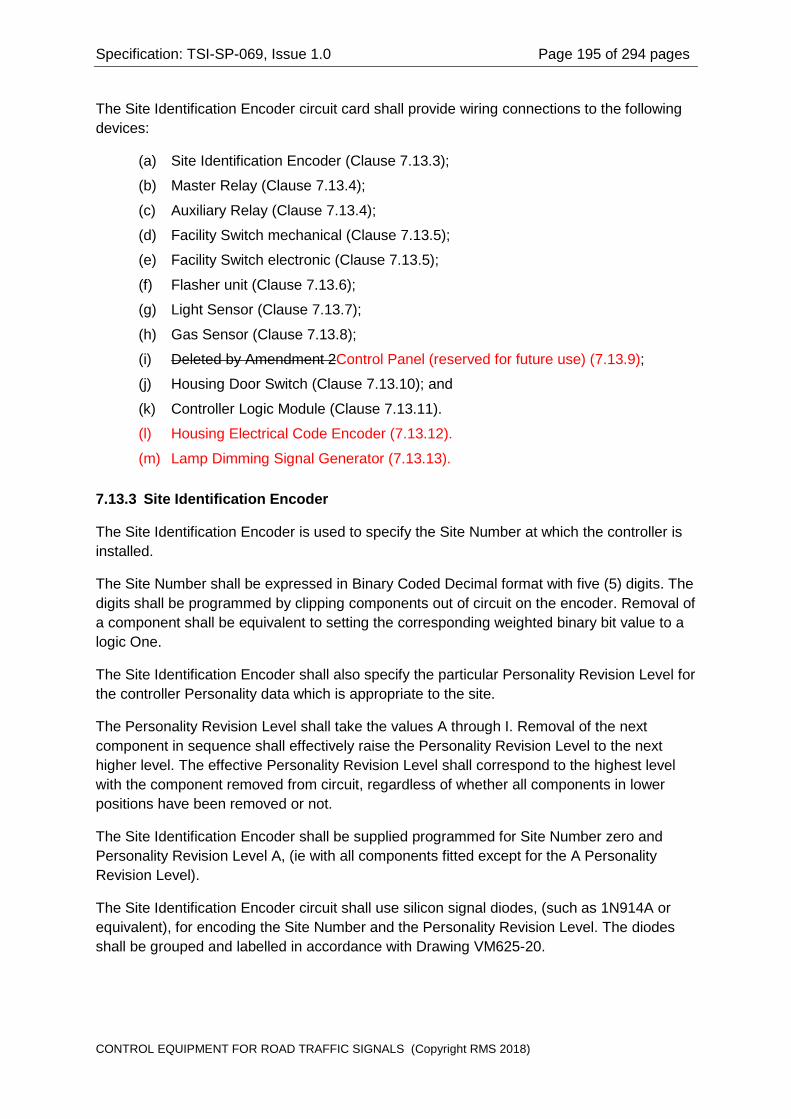
Specification: TSI-SP-069, Issue 1.0 Page 195 of 294 pages
The Site Identification Encoder circuit card shall provide wiring connections to the following devices:
(a) Site Identification Encoder (Clause 7.13.3);
(b) Master Relay (Clause 7.13.4);
(c) Auxiliary Relay (Clause 7.13.4);
(d) Facility Switch mechanical (Clause 7.13.5);
(e) Facility Switch electronic (Clause 7.13.5);
(f) Flasher unit (Clause 7.13.6);
(g) Light Sensor (Clause 7.13.7);
(h) Gas Sensor (Clause 7.13.8);
(i) Deleted by Amendment 2Control Panel (reserved for future use) (7.13.9);
(j) Housing Door Switch (Clause 7.13.10); and
(k) Controller Logic Module (Clause 7.13.11).
(l) Housing Electrical Code Encoder (7.13.12).
(m) Lamp Dimming Signal Generator (7.13.13).
7.13.3 Site Identification Encoder
The Site Identification Encoder is used to specify the Site Number at which the controller is installed.
The Site Number shall be expressed in Binary Coded Decimal format with five (5) digits. The digits shall be programmed by clipping components out of circuit on the encoder. Removal of a component shall be equivalent to setting the corresponding weighted binary bit value to a logic One.
The Site Identification Encoder shall also specify the particular Personality Revision Level for the controller Personality data which is appropriate to the site.
The Personality Revision Level shall take the values A through I. Removal of the next component in sequence shall effectively raise the Personality Revision Level to the next higher level. The effective Personality Revision Level shall correspond to the highest level with the component removed from circuit, regardless of whether all components in lower positions have been removed or not.
The Site Identification Encoder shall be supplied programmed for Site Number zero and Personality Revision Level A, (ie with all components fitted except for the A Personality Revision Level).
The Site Identification Encoder circuit shall use silicon signal diodes, (such as 1N914A or equivalent), for encoding the Site Number and the Personality Revision Level. The diodes shall be grouped and labelled in accordance with Drawing VM625-20.
CONTROL EQUIPMENT FOR ROAD TRAFFIC SIGNALS (Copyright RMS 2018)

Specification: TSI-SP-069, Issue 1.0 Page 196 of 294 pages
7.13.4 Master Relay and Auxiliary Relay Connections (ZMR)
The connections to the Master Relay and the Auxiliary Relay shall share a common connector (ZMR) to the Site Identification Encoder circuit card.
NOTE: Refer to Table G.1.6 in Appendix G and the Site Identification Encoder circuit, Drawing VE533-17 for the pin connections.
The Master Relay shall have the following connections to the Site Identification Encoder circuit card:
(a) Coil (+);
(b) Coil (-);
(c) Normally Open control contact set, (2 connections).
The Auxiliary Relay shall have the following connections to the Site Identification Encoder circuit card:
(a) Coil (+);
(b) Coil (-);
(c) Normally Open control contact set, (2 connections).
The Site Identification Card shall provide mounting for a suppression network for the Master Relay coil. The suppression network shall be designed to minimise the release (de operate) time of the Master Relay and to quench the back-emf from the coil.
NOTE: The suppression network shall be a silicon avalanche diode such as type 1N5060, with a series connected 24 V 3 W zener diode. Refer to Clause 6.5.7.4.
The Site Identification Card shall provide mounting for a back-emf diode for the Auxiliary Relay coil. The diode shall be a silicon avalanche type, such as type 1N5060.
The wander lead connector shall have a link for sensing that the connector is mated to the Site Identification Encoder circuit card.
The pin functions for the wander lead connector at the Site Identification Encoder shall be as specified in Table G.1.6 in Appendix G.
7.13.5 Facility Switch Connections (ZSW)
The connections to the Facility Switch shall share a common connector (ZSW) to the Site Identification Encoder circuit card.
NOTE: Refer Table G.1.8 in Appendix G and the Site Identification Encoder circuit, Drawing VE533-17 for the pin connections.
The Site Identification Encoder circuit card shall make provision for both a Mechanical Facility Switch and an Electronic Facility Switch. The controller logic circuits shall sense which of these is provided in the housing and respond accordingly.
CONTROL EQUIPMENT FOR ROAD TRAFFIC SIGNALS (Copyright RMS 2018)

Specification: TSI-SP-069, Issue 1.0 Page 197 of 294 pages
NOTE: The Electronic Facility Switch will be specified in a future amendment to this Specification.
The Mechanical Facility Switch shall have the following connections to the Site Identification Encoder circuit card:
(a) Facility Switch position encoding contacts, (3 connections);
(b) Connector sensing link, (2 connections);
(c) Master Relay contact, (2 connections);
(d) Auxiliary Relay contact, (2 connections);
(e) Disable Flasher unit, (2 connections).
The Electronic Facility Switch shall have the following connections to the Site Identification Encoder circuit card:
(a) Electronic sensing device, (3 connections);
(b) Connector sensing link, (2 connections);
(c) Master Relay coil connection, (2 connections);
(d) Auxiliary Relay coil connection, (2 connections);
(e) Disable Flasher unit, (2 connections).
For the Mechanical Facility Switch, the coil drives to the Master Relay and the Auxiliary Relay shall be switched by contacts on the Facility Switch.
For the Electronic Facility Switch, the continuity of the coil drive to the Master Relay and the Auxiliary Relay will be controlled by circuits within the Electronic Facility Switch.
In the Off position, the Facility Switch shall provide a logic ground to the Facility Switch Disable Flasher input at the Flasher unit to disable the Flashing Active outputs from the Flasher unit.
The wander lead connector shall have a link for sensing that the connector is mated to the Site Identification Encoder circuit card. For the case of the Mechanical Facility Switch, the link shall be formed by two wires in the wander lead which are terminated at a common terminal at the Facility Switch.
The pin functions for the wander lead connector at the Site Identification Encoder shall be as specified in Table G.1.8 in Appendix G.
7.13.6 Flasher Unit Connections (ZFL)
The Extra Low Voltage connections to the Flasher unit shall share a common connector (ZFL) to the Site Identification Encoder circuit card.
NOTE: Refer to Table G.1.2 in Appendix G and the Site Identification Encoder circuit, Drawing VE533-17 for the pin connections.
CONTROL EQUIPMENT FOR ROAD TRAFFIC SIGNALS (Copyright RMS 2018)

Specification: TSI-SP-069, Issue 1.0 Page 198 of 294 pages
The wander lead connector shall have a pair of conductors for sensing that the connector is mated to the Site Identification Encoder circuit card and that the Extra Low Voltage connector is mated at the Flasher unit. The sensing link is internal to the Flasher unit.
The pin functions for the wander lead connector at the Site Identification Encoder shall be as specified in Table G.1.2 in Appendix G.
7.13.7 Light Sensor Connections (ZLS)
The connections to the Light Sensor shall share a common connector (ZLS) to the Site Identification Encoder circuit card.
NOTE: Refer to Table G.1.5 in Appendix G and the Site Identification Encoder circuit, Drawing VE533-17 for the pin connections.
The wander lead connector shall have a link for sensing that the connector is mated to the Site Identification Encoder circuit card.
The pin functions for the wander lead connector at the Site Identification Encoder shall be as specified in Table G.1.5 in Appendix G.
7.13.8 Gas Sensor Connections (ZGS)
The connections to the Gas Sensor shall share a common connector (ZGS) to the Site Identification Encoder circuit card.
NOTE: Refer to Table G.1.3 in Appendix G and the Site Identification Encoder circuit, Drawing VE533-17 for the pin connections.
The wander lead connector shall have a link for sensing that the connector is mated to the Site Identification Encoder circuit card.
The pin functions for the wander lead connector at the Site Identification Encoder shall be as specified in Table G.1.3 in Appendix G.
The provision of a Gas Sensor is only required at specific sites, typically within a city or township. The wander lead and connector for the Gas Sensor will be fitted in the workshop as required, however, the header connector for the Gas Sensor shall be fitted to the Site Identification Encoder circuit card.
7.13.9 No Longer Used Control Panel Connections (ZPC)
Section deleted by Amendment 2
The connections to the Control Panel reserved for future use shall share a common connector (ZPC) to the Site Identification Encoder circuit card.
NOTE: Refer to Table G.1.7 in Appendix G and the Site Identification Encoder circuit, Drawing VE 533-17 for the pin connections.
The wander lead connector shall have a link for sensing that the connector is mated to the Site Identification Encoder circuit card.
CONTROL EQUIPMENT FOR ROAD TRAFFIC SIGNALS (Copyright RMS 2018)

Specification: TSI-SP-069, Issue 1.0 Page 199 of 294 pages
The pin functions for the wander lead connector at the Site Identification Encoder shall be as specified in Table G.1.7 in Appendix G.
NOTE: The Control Panel is reserved for future use, and provision of the Control Panel is not required at present. The wander cable for the Control Panel is not required to be fitted and the header connector for the Control Panel is not required to be fitted to the Site Identification Encoder circuit card.
7.13.10 Housing Door Switch Connections (ZDR)
The connections to the housing door switch shall share a common connector (ZDR) to the Site Identification Encoder circuit card.
NOTE: Refer to Table G.1.1 in Appendix G and the Site Identification Encoder circuit, Drawing VE533-17 for the pin connections.
The wander lead connector shall have a link for sensing that the connector is mated to the Site Identification Encoder circuit card.
The pin functions for the wander lead connector at the Site Identification Encoder shall be as specified in Table G.1.1 in Appendix G.
7.13.11 Controller Logic Module Connections (ZID)
The connections to the Logic Module shall share a common connector (ZID) to the Site Identification Encoder circuit card.
NOTE: Refer to Table G.1.4 in Appendix G and the Site Identification Encoder circuit, Drawing VE533-17 for the pin connections.
The Site Identification Encoder circuit card shall provide a diode link to allow the controller logic circuits to determine whether the connector is mated to the Site Identification Encoder circuit card.
The pin functions for the wander lead connector at the Site Identification Encoder shall be as specified in Table G.1.4 in Appendix G.
7.13.12 Housing Electrical Code Encoder Connections (ZHC)
The connections to the Housing Electrical Code Encoder unit shall share a common connector (ZHC) to the Site Identification Encoder circuit card.
NOTE: Refer to Table G.1.9 in Appendix G and the Site Identification Encoder circuit, Drawing VE 533-17 for the pin connections.
NOTE: Refer to Clause 7.25 for requirements for the Housing Electrical Code Encoder.
The wander lead connector shall have a link for sensing that the connector is mated to the Site Identification Encoder circuit card.
The wander lead shall be securely attached to the housing.
CONTROL EQUIPMENT FOR ROAD TRAFFIC SIGNALS (Copyright RMS 2018)

Specification: TSI-SP-069, Issue 1.0 Page 200 of 294 pages
The pin functions for the wander lead connector at the Site Identification Encoder shall be as specified in Table G.1.9 in Appendix G.
7.13.13 Lamp Dimming Signal Generator Connections (ZDC)
The connections to the Lamp Dimming Signal Generator shall share a common connector (ZDC) to the Site Identification Encoder circuit card.
NOTE: Refer to Table G.1.10 in Appendix G and the Site Identification Encoder circuit, Drawing VE 533-17 for the pin connections.
The wander lead shall be securely attached to the housing.
The pin functions for the wander lead connector at the Site Identification Encoder shall be as specified in Table G.1.10 in Appendix G.
7.13.14 Mounting, Visibility and Accessibility
The Site Identification Encoder circuit card shall be mounted in a convenient position in the housing which will not provide any risk of damage to either the circuit card, or the cabling to the circuit card, by equipment being installed into or removed from the housing during normal maintenance activities.
The mounting position shall be accessible to allow the Site Number and Personality Revision Level to be conveniently programmed. It is acceptable for plug-in equipment, (such as the Logic Module), to be removed from the housing to gain access to the Site Identification Encoder.
The mounting position shall provide good visibility of the encoding of the Site Number and the Personality Revision Level without removal of panels or equipment.
The Site Identification Encoder circuit card shall be readily removed from and replaced into the controller housing in the field, without the need for any special tools or equipment.
The Site Identification Encoder circuit card shall be mounted in the housing by means of four (4) 3 mm studs to mate with the mounting holes indicated on Drawing VM625-20.
The Site Identification Encoder arrangement drawing (VM625-20) details additional holes for the mounting of a protective perspex cover. These holes shall not to be used as alternative mounting holes for the Site Identification Encoder circuit card.
7.14 Telecommunications Line Isolation Transient Protection Unit
7.14.1 Conformance with ACA ACMA Standards
The Line Isolation Unit Telecommunications Line Transient Protection Unit shall be approved by a registered testing authority for compliance with the relevant requirements of ACA ACMA Standards. Documentary evidence shall be supplied to confirm the approval when the equipment is submitted to the Authority for Type Approval.
CONTROL EQUIPMENT FOR ROAD TRAFFIC SIGNALS (Copyright RMS 2018)

Specification: TSI-SP-069, Issue 1.0 Page 201 of 294 pages
NOTE: The testing authority will require the complete equipment for testing the isolation provided to the telecommunications line, and for testing the signal levels applied to the telecommunications line. The Line Isolation Unit will be inspected for both the mechanical arrangement and the isolation circuit employed.
NOTE: Drawing VM621-31 VM621-32 shows a mechanical arrangement for the Telecommunications Line Isolation Unit. The arrangement in the drawing should be considered as an illustration of the requirements rather than as a design required by this Specification.
7.14.2 Function and Circuit Description
The Line Isolation Unit shall isolate the telecommunications line from voltages present in the control equipment and shall protect the control equipment from induced voltages on the telecommunications line, such as from lightning discharges. The protection circuit shall comply with AS/NZS 60950.1.
The circuit shall employ an ACA ACMA approved Line Isolation Transformer with an electrostatic screen between the primary and secondary windings, and additional protection devices.
The Telecommunications Line Transient Protection Unit shall provide protection against transients and surges present on the telecommunications line by limiting the transient and surge voltage presented to the control equipment to protect the equipment. The protection circuit shall comply with AS/NZS 60950.1.
The protection circuit on the line side of the Line Isolation Transformer Telecommunications Line Transient Protection Unit shall include:
(a) a three (3) terminal gas discharge arrester; and
(b) other surge suppression devices, such as Metal Oxide Varistors (MOVs).
The protection circuit on the equipment side of the Line Isolation Transformer shall include:
(a) surge suppression devices, such as silicon transient voltage suppression devices, (eg. TransZorb® diodes); and
(b) an isolating capacitor rated for mains voltage operation.
The protection circuit on the equipment side of the Telecommunications Line Transient Protection Unit shall include surge suppression devices, such as silicon transient voltage suppression devices.
The protection circuits shall not include fuses with replaceable fuse cartridges; however low-value or zero-ohm resistors which are soldered into circuit may be used as fusible links in the protection circuits.
The protection circuits shall limit the surge voltage presented to the control equipment to less than 10 volts peak of either polarity.
CONTROL EQUIPMENT FOR ROAD TRAFFIC SIGNALS (Copyright RMS 2018)
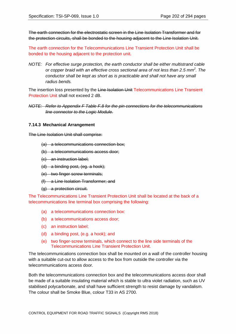
Specification: TSI-SP-069, Issue 1.0 Page 202 of 294 pages
The earth connection for the electrostatic screen in the Line Isolation Transformer and for the protection circuits, shall be bonded to the housing adjacent to the Line Isolation Unit.
The earth connection for the Telecommunications Line Transient Protection Unit shall be bonded to the housing adjacent to the protection unit.
NOTE: For effective surge protection, the earth conductor shall be either multistrand cable or copper braid with an effective cross sectional area of not less than 2.5 mm2. The conductor shall be kept as short as is practicable and shall not have any small radius bends.
The insertion loss presented by the Line Isolation Unit Telecommunications Line Transient Protection Unit shall not exceed 2 dB.
NOTE: Refer to Appendix F Table F.8 for the pin connections for the telecommunications line connector to the Logic Module.
7.14.3 Mechanical Arrangement
The Line Isolation Unit shall comprise:
(a) a telecommunications connection box;
(b) a telecommunications access door;
(c) an instruction label;
(d) a binding post, (eg. a hook);
(e) two finger screw terminals;
(f) a Line Isolation Transformer; and
(g) a protection circuit.
The Telecommunications Line Transient Protection Unit shall be located at the back of a telecommunications line terminal box comprising the following:
(a) a telecommunications connection box:
(b) a telecommunications access door;
(c) an instruction label;
(d) a binding post, (e.g. a hook); and
(e) two finger-screw terminals, which connect to the line side terminals of the Telecommunications Line Transient Protection Unit.
The telecommunications connection box shall be mounted on a wall of the controller housing with a suitable cut-out to allow access to the box from outside the controller via the telecommunications access door.
Both the telecommunications connection box and the telecommunications access door shall be made of a suitable insulating material which is stable to ultra violet radiation, such as UV stabilised polycarbonate, and shall have sufficient strength to resist damage by vandalism. The colour shall be Smoke Blue, colour T33 in AS 2700.
CONTROL EQUIPMENT FOR ROAD TRAFFIC SIGNALS (Copyright RMS 2018)

Specification: TSI-SP-069, Issue 1.0 Page 203 of 294 pages
The telecommunications access door shall be provided with a concealed hinge made from a non-corrodible material, such as stainless steel. The telecommunications access door shall be provided with a lock, with key combination ZA0805 to Drawing VM005-4.
The telecommunications access door shall not be embossed with any logo or legend.
The telecommunications line shall enter the controller housing via the telecommunications access conduit (Clause 7.14.9). The telecommunications access conduit shall provide access for the telecommunications line into the telecommunications connection box.
The telecommunications connection box shall provide a binding post and two finger screw type terminations for the telecommunications line. The terminals shall be connected to the line side of the Line Isolation Transformer Telecommunications Line Transient Protection Unit.
The Line Isolation Transformer and protection circuit Telecommunications Line Transient Protection Unit shall be mounted on the outside of the telecommunications connection box, ie inside the controller, and shall be enclosed within an insulating cover. Non-metallic, (such as nylon), mounting hardware shall be used if the fasteners enter inside the telecommunications connection box.
7.14.4 Provision for Telephone Wall-Socket Connector Cable and Connector for PSTN Modem Connection
An external modem, (ie a modem external to the Logic Module, but mounted within the controller housing), may be used to provide dial-up connection to the SCATS master over the Public Switched Telephone Network. In such case the internal modem in the Logic Module must be disabled.
When an external modem is used, the Line Isolation Transformer and protection circuits will be replaced by a different protection circuit suitable for passing ring voltages. A standard telephone connector, (600 series wall-socket or RJ series modular connector), will be fixed to the Line Isolation Unit for connection of the modem to the telecommunications line.
The Line Isolation Unit shall make provision for the requirements for use of an external modem.
The connection to the PSTN modem connector XRJ shall be a cable complete with a 6P2C (RJ11) connector (plug) for the connection and be ACMA approved.
The complete cable with connector(s) shall comply with the relevant requirements for cordage and cords in AS/ACIF S008.
NOTE: Refer to Table F.19 in Appendix F for the pin connections for the PSTN modem connection to the Logic Module
7.14.5 Mounting
The telecommunications connection box shall be mounted inside the controller housing with a cut-out in the housing to provide access via the telecommunications access door.
CONTROL EQUIPMENT FOR ROAD TRAFFIC SIGNALS (Copyright RMS 2018)

Specification: TSI-SP-069, Issue 1.0 Page 204 of 294 pages
For the ground-mounted controller, the telecommunications connection box shall be located on the right hand side of the housing, as viewed from the front of the housing, (refer to Drawing VM621-31). The telecommunications connection box shall be mounted at a height not less than one (1) metre above the controller base.
For the post-mounted controller, the telecommunications connection box shall be located below the front access door to the housing. Refer to Drawing VM625-17 for details.
7.14.6 Weatherproofing
The mounting of the telecommunications connection box to the housing wall shall provide a weatherproof seal to comply with the requirements of Clause 8.7.
The telecommunications access door shall seal against a suitable gasket, made from an ultra-violet stable closed cell material, to provide weatherproofing. The interior of the telecommunications connection box shall be sealed to prevent entry of water into the controller housing.
The gasket sealing the telecommunications access door shall have a void on the lower edge to provide drainage from the telecommunications connection box.
7.14.7 Instruction Label
An Instruction Label shall be permanently affixed to the inside of the telecommunications access door. The label shall be made from a durable material such as plastic film or metal (eg. metalcal) which can be marked by a pen, (such as an indelible felt point pen).
The Instruction Label shall provide space for recording the NEX Telephone Line Number for the telecommunications line. The label shall also have the legend, "WIND TELECOMMUNICATIONS CABLE AROUND HOOK BEFORE TERMINATING". The figure below provides a guide for the format of the Instruction Label.
CONTROL EQUIPMENT FOR ROAD TRAFFIC SIGNALS (Copyright RMS 2018)

Specification: TSI-SP-069, Issue 1.0 Page 205 of 294 pages
NEX TELEPHONE LINE No ...
WIND TELECOMMUNICATIONS CABLE AROUND HOOK BEFORE TERMINATING
7.14.8 Resistance to Vandalism
The telecommunications connection box and telecommunications access door shall be suitably reinforced with ribbing and/or webbing to provide adequate strength to resist damage by vandalism.
For the ground-mounted housing the mounting position shall be as high as practicable to preclude damage by kicking.
7.14.9 Telecommunications Access Conduit
A telecommunications access conduit shall be provided in the housing for a telecommunications line. The conduit shall have a nominal internal diameter of 20 mm, shall be white in colour, and shall be ACA ACMA approved.
The conduit shall begin, (bell coupling), at the housing base and shall end inside the telecommunications connection box. The conduit entry to the telecommunications connection box shall be sealed to prevent water entry into the housing, but there is no requirement for sealing the inside of the conduit.
For ground-mounted controllers, the conduit shall be secured by saddles or clamps in the housing but shall have free movement at the base of the housing to facilitate mating with a conduit cast into the concrete footing. The position of the conduit relative to the controller mounting bolts is specified by Drawing VC002-24.
The telecommunications access conduit shall not enclose any wiring other than the telecommunications line.
CONTROL EQUIPMENT FOR ROAD TRAFFIC SIGNALS (Copyright RMS 2018)

Specification: TSI-SP-069, Issue 1.0 Page 206 of 294 pages
7.15 Light Sensor
7.15.1 Function
A Light Sensor shall be used to sense the ambient light level in the vicinity of the controller.
The Light Sensor shall indicate "Night" when the ambient light level falls below 30 Lux, and shall indicate "Day" when the ambient light level rises above 150 Lux.
NOTE: The above figures for light level are nominal figures. The hysteresis in changing the indication between Night and Day shall be provided by a software algorithm rather than by a hardware circuit. Refer to Clause 6.6.3.6.
NOTE: Refer to Drawing VE533-17 and Clause 7.13.7 for details of wiring connections to the Light Sensor.
NOTE: Refer to Clause 6.5.10 for details relating to the interface circuitry for the Light Sensor.
7.15.2 Type
The Light Sensor shall be a Silicon NPN photo-transistor, equivalent to the type specified in Clause I.5 in Appendix I.
7.15.3 Mounting
The Light Sensor shall be mounted on the front face of the controller above the access door. The sensor shall be mounted in an unobtrusive manner in the gap between the housing roof and the door. The Light Sensor shall have a field of view with an axis normal to the front of the housing.
The mounting holder shall be made from a translucent, optically stable, high impact plastic material and shall have sufficient strength to resist damage by vandalism. The material used shall be stable to ultra violet radiation and shall not deteriorate due to thermal effects over the temperature extremes specified in Clause 8.1.
The Light Sensor mounting shall be as small as practicable to achieve the function and shall be designed such as not to attract the attention of vandals.
The mounting method and the wiring to the Light Sensor shall be arranged to prevent inadvertent contact of the Light Sensor or its associated wiring with Low Voltage circuits.
7.15.4 Weatherproofing
The Light Sensor mounting shall provide a weatherproof seal to prevent entry of water and dust into the housing, with the degree of protection specified in Clause 8.7.
NOTE: Ultra violet stable Silicone sealants may be used to provide the sealing of the Light Sensor mounting to the housing.
CONTROL EQUIPMENT FOR ROAD TRAFFIC SIGNALS (Copyright RMS 2018)

Specification: TSI-SP-069, Issue 1.0 Page 207 of 294 pages
7.15.5 Resistance to Vandalism
The Light Sensor and mounting shall be designed to resist damage by vandalism.
7.16 Gas Sensor
7.16.1 Function
A Gas Sensor shall be used to sense the presence of combustible gases inside the controller housing.
The ground-mounted housing shall make provision for mounting the Gas Sensor and associated interface circuit, and for the installation of a wander cable from the interface circuit to the Site Identification Encoder circuit card. These will be fitted in the workshop or on site as required.
NOTE: The provision of a Gas Sensor is only required at specific sites, typically within a city or township.
NOTE: Refer to Drawings VE533-17 and VE533-23, and Clause 7.13.8 for details of wiring connections to the Gas Sensor.
7.16.2 Type
The Gas Sensor shall be a semiconductor device. The device type shall be equivalent to the type specified in Clause I.6 in Appendix I.
7.16.3 Sensing Threshold
The Gas Sensor interface circuit shall provide a combustible gas detection threshold of between one (1) and twenty-five (25) percent of the lower explosive limit of the gases, over the temperature range -10ºC and +40ºC, and relative humidity up to 90%.
The interface circuit shall not require calibration.
NOTE: The sensing threshold is intended to provide early warning that combustible gases are present in the controller housing before the concentration is sufficient to cause an explosion. The threshold should not be set to a level which produces nuisance warnings.
7.16.4 Gas Sensor Interface Circuit
The Gas Sensor requires a controlled voltage to the heating element and a resistance measurement for its sensing element to determine the presence of combustible gases.
The output circuit for the Gas Sensor interface circuit shall be an open-collector transistor.
CONTROL EQUIPMENT FOR ROAD TRAFFIC SIGNALS (Copyright RMS 2018)

Specification: TSI-SP-069, Issue 1.0 Page 208 of 294 pages
The output from the Gas Sensor interface circuit shall provide a current sink of 20 mA minimum to the logic common when combustible gases present in the controller housing are below the detection threshold.
The output from the Gas Sensor interface circuit shall have a maximum leakage current of 1 mA to the logic common when combustible gases present in the controller housing are above the detection threshold.
NOTE: Drawing VE533-23 illustrates an interface circuit derived from an application note for the Gas Sensor specified in Clause I.6 in Appendix I.
7.16.5 Mounting
The Gas Sensor and interface circuit shall be mounted in a position not higher than 300 mm above the base of the housing.
The Gas Sensor shall be mounted in a position which precludes inadvertent contact of both the Gas Sensor and its associated interface circuit and wiring with Low Voltage circuits.
7.16.6 Protective Coating
The Gas Sensor interface circuit, except for the Gas Sensor device, shall be protected from the environment by a conformal coating or a spray on lacquer designed for this purpose. The coating used shall be a solder-through type. Refer to Appendix I.8.
7.17 No Longer Used Lamp Dimming Signal Generator
Section deleted in Amendment 2
7.17.1 Function
The Lamp Dimming Signal Generator generates the lamp dimming control signal required by compatible traffic signal lanterns to control their dimming operation in accordance with Clause 6.6.3.2.
The Lamp Dimming Signal Generator shall provide the following inputs and outputs:
(a) Two inputs for receiving the two Dimming Control outputs (Clause 6.5.30) from the CPU module in the Logic Module. Refer to Clauses 7.17.2;
(b) A feedback voltage (i.e. feedback signal) for connection to the Dimming Control Monitor input (Clause 6.5.30) of the CPU module. Refer to (Clause 7.17.3);
(c) A lamp dimming control signal for direct connection to traffic signal lanterns to signify dimmed or undimmed operations. Refer to Clause 7.17.4.
NOTE: Refer to Table G.1.10 in Appendix G for connector (ZDC) pin functions.
7.17.2 Dimming Control Inputs
The Dimming Control inputs shall sense the state of Dimming Control outputs (Clause 6.5.30.2) from the CPU Module. The Lamp Dimming Signal Generator shall accordingly generate the corresponding lamp dimming control signal (Clause 7.17.4).
CONTROL EQUIPMENT FOR ROAD TRAFFIC SIGNALS (Copyright RMS 2018)
Specification: TSI-SP-069, Issue 1.0 Page 209 of 294 pages
7.17.3 Dimming Control Monitor Output
The Lamp Dimming Signal Generator shall generate an electrical replica of the lamp dimming control signal (Clause 7.17.4) at a reduced amplitude as the feedback signal to the Logic Module (see Clauses 6.5.30.1 and 6.5.30.3).
The feedback signal shall conform to the following requirements:
(a) Be an electrical replica of the lamp dimming control signal but at a reduced amplitude. The amplitude reduction shall be such that a lamp dimming control signal with a voltage (in r.m.s. value) equal to the rated lamp supply voltage is scaled to 8.0 V;
(b) Be electrically isolated from the lamp dimming control signal circuit. The isolation shall be equivalent to that provided by a safety isolating transformer complying with AS/NZS 61558.2.6.
7.17.4 Lamp Dimming Control Signal
The form of lamp dimming control signal shall be in accordance with Table 6.5.30.2 and Clause 6.6.3.2.
The lamp dimming control signal shall be able to supply an overall load current of 1.0 A r.m.s. in the required voltage range.
The lamp dimming control signal circuit shall be protected against current overload by fusing and/or electronic current-limit protection circuitry.
7.17.5 Indicator Lights
Two LED indicators, one red and one green, shall be provided on the Lamp Dimming Signal Generator at a readily visible location for the following purpose:
(a) The RED indicator shall light up only when the Lamp Dimming Signal Generator is generating a signal that signifies dimmed mode of traffic signal lanterns;
(b) The GREEN indicator shall light up only when the Lamp Dimming Signal Generator is generating a signal that signifies undimmed mode of traffic signal lanterns.
The LED indicators shall be high intensity types with clear packages and shall provide unambiguous displays with good visibility in direct sunlight.
7.17.6 Mounting, Visibility and Accessibility
The Lamp Dimming Signal Generator shall be mounted in accordance with Drawing VM625-24.
The method of mounting shall be such that each component can be readily replaced in the field, including incoming and outgoing wiring, without the need for special tools or equipment.
CONTROL EQUIPMENT FOR ROAD TRAFFIC SIGNALS (Copyright RMS 2018)

Specification: TSI-SP-069, Issue 1.0 Page 210 of 294 pages
All LED indicators on the Lamp Dimming Signal Generator shall be clearly visible when the controller access door is open, without the need to remove or swing back any panel or equipment.
7.17.7 Connection to the Site Identification Card (Connector ZDC)
The wiring from the Lamp Dimming Signal Generator shall be terminated in a female connector which shall mate with the corresponding header connector (ZDC) on the Site Identification Card.
The pin connections for connector ZDC shall be as specified in Table G.1.4 in Appendix G.
NOTE: For connections between the housing wiring and the Lamp Dimming Signal Generator, refer to Drawing VE533-17.
7.18 Housing Door Switch
7.18.1 Function
A door switch shall be used to sense that the controller housing door is open or incorrectly secured.
The switch shall provide a normally open contact set. The contact shall be closed when the housing door is secured and open when the door is open or incorrectly secured.
The housing door switch shall provide a positive indication of the position of the housing door. The door switch shall provide positive indication regardless of aging of the door sealing gasket.
NOTE: Refer to Drawing VE533-17 and Clause 7.13.10 for details of wiring connections to the door switch.
7.18.2 Type
The door switch shall be an industrial grade microswitch or similar switch suitable for use in the environment specified in Clauses 8.1 and 8.2.
The switch shall provide an isolated normally open contact set.
The switch actuating mechanism shall provide positive actuation of the switch contact with the housing door in the secured position.
The contacts shall be rated for switching Extra-Low Voltage control signals, operating at voltages of nominally 12 V d.c. and currents of 1 to 10 mA.
7.18.3 Mounting
The housing door switch and associated wiring shall be mounted in a position which:
CONTROL EQUIPMENT FOR ROAD TRAFFIC SIGNALS (Copyright RMS 2018)

Specification: TSI-SP-069, Issue 1.0 Page 211 of 294 pages
(a) is unobtrusive;
(b) minimises the possibility of damage by normal maintenance activities; and
(c) provides protection against rain and weather when the housing door is open.
NOTE: Attention is drawn to the requirements of Clause 7.22 regarding segregation of ELV circuits from Low Voltage circuits.
7.19 Extra Low Voltage (ELV) Transformer
7.19.1 Function
An Extra Low Voltage Transformer shall be provided for supplying alternating voltage to the detector and pushbutton interface circuits.
The transformer shall provide a single secondary winding. One side of the secondary winding shall be connected to the Detector Common Terminals on the E terminal block. Refer to Clause 7.6.5 and Drawings VE533-18 and VE533-19.
NOTE: The Detector Common is connected to Earth.
The supply voltage to the transformer primary shall be controlled by the Logic Circuit Breaker on the switchboard.
7.19.2 Type, Voltage and Rating
The Extra Low Voltage Transformer shall be a safety isolating transformer complying with the requirements of AS 3108 AS/NZS 61588.2.6. The transformer shall not have a built in thermal cut-out.
The transformer shall provide a voltage of 32 V r.m.s. +/- 10% at the secondary winding at the rated load with the nominal mains supply voltage specified in Clause 8.3.1 applied to the primary winding.
The minimum transformer secondary current rating shall be 1 A.
The transformer regulation shall be better than 5% over the range of load currents from zero to the full rated current.
7.19.3 Fusing and Connections
The transformer shall be protected against overload by a replaceable cartridge fuse connected in series with the secondary winding. The cartridge fuse shall be an anti-surge 20 mm by 5 mm glass cartridge type.
The fuse rating shall be specified for the full rated load current of the transformer secondary.
The fuse holder shall be mounted on the transformer in an accessible position.
The transformer windings shall be terminated in melamine terminal blocks mounted in accessible positions on the transformer. The terminal blocks shall allow connection of the
CONTROL EQUIPMENT FOR ROAD TRAFFIC SIGNALS (Copyright RMS 2018)

Specification: TSI-SP-069, Issue 1.0 Page 212 of 294 pages
housing wiring to the transformer without loosening or dislodging the connections to the transformer windings or the fuse.
NOTE: Special precautions may be necessary for the connections to the transformer windings, fuse and terminal blocks to meet the requirements of Clause 7.24.2.
7.19.4 Mounting, Visibility and Accessibility
The transformer shall be mounted in a convenient position in the housing. The transformer shall be accessible for termination of wiring and accessible for removal and replacement of the fuse cartridge.
The mounting method and position shall not obscure the markings on the transformer.
7.19.5 Marking
The transformer connections shall be marked adjacent to the terminal blocks mounted on the transformer.
The fuse rating shall be legibly and indelibly marked on the transformer.
NOTE: Refer to Clause 5.1.3 in Specification ECA/2 for the requirements for markings for the transformer.
7.20 Equipment Mounting Space
7.20.1 Shelf Space
For the ground-mounted controller, clear shelf space shall be provided for free-standing ancillary equipment.
The clear shelf space shall not be less than:
(a) 225 mm wide;
(b) 260 mm deep; and
(c) 350 mm high.
7.20.2 Blank Panel Space
For the ground-mounted controller, clear vertical panel space shall be provided for mounting ancillary equipment such as transformers and contactors.
The vertical panel space shall not be less than 300 mm by 180 mm, with a clear space of 180 mm in front of the panel.
7.21 Connectors
CONTROL EQUIPMENT FOR ROAD TRAFFIC SIGNALS (Copyright RMS 2018)

Specification: TSI-SP-069, Issue 1.0 Page 213 of 294 pages
7.21.1 Interface Connectors
This Specification requires the use of specific connector types for interfacing the housing circuits to the Logic Module in order to provide compatibility between equipment from different suppliers.
The connectors used in the equipment shall be the specified types, or types which are directly equivalent with regard to mating to the corresponding connector.
The pin functions for the interface circuits shall be as specified in this Specification.
The location and length of interfacing connector leads shall be in accordance with Drawing VM625-28.
7.21.2 Connector Sensing and Encoding
Sensing circuitry shall be provided for each connector to allow the control program to determine which connectors have been mated and which connectors have not been mated.
The control program shall use the connector sensing to confirm that the connectors have been mated correctly.
The sensing circuitry shall rely upon a link in a mating connector or upon a signal which must always be present in a mating connector. Sensing links and diodes shall be provided as specified in the relevant clauses of this Specification.
NOTE: The connectors for signal group outputs use diodes for connector sensing and encoding. Refer to Table F.1c in Appendix F.
NOTE: Connectors which are not required to have a sensing link are specifically noted in the appropriate clauses relating to those connectors.
7.21.3 Connector Coding or Keying
As far as practicable, the equipment shall be designed using different connector types, or different connector keying, to prevent incorrect mating of the connectors.
7.21.4 Connector Backshells
As far as practicable, all wander lead connectors shall be fitted with backshells to provide strain relief for the cables in the wander lead.
Connector backshells shall be non-metallic.
7.21.5 Connector Retention
All wander lead connectors shall be fitted with retaining devices to provide secure mating and retention of each connector pair.
CONTROL EQUIPMENT FOR ROAD TRAFFIC SIGNALS (Copyright RMS 2018)

Specification: TSI-SP-069, Issue 1.0 Page 214 of 294 pages
7.21.6 Safety Requirements
Connectors with Low Voltage at any terminal shall have shrouded or recessed terminals to preclude inadvertent contact by personnel.
Where Low Voltage is present in a connector, appropriate insulation shall be provided to segregate any Extra-Low Voltage wiring in the same connector. Particular care shall be taken to segregate the sensing links or diodes in the connector from Low Voltage.
7.22 Wiring
7.22.1 Safety Standards
The housing wiring shall comply with the safety standards specified in AS 3000, AS 3100, AS/NZS 60950.1 and the requirements of the NSW Occupational Health and Safety Act.
7.22.2 Type and Rating
The housing circuits shall be wired with flexible multistrand cable having PVC or Elastomeric insulation rated for continuous operation at not less than 75ºC.
The switchboard wiring shall use flexible cables, or cables with a minimum of seven (7) strands, having PVC or Elastomeric insulation rated for continuous operation at not less than 75ºC.
Cables in Low Voltage circuits shall have a minimum conductor size of 1.5 mm2. Cables which are bundled in looms shall be appropriately derated for current carrying capacity.
Cables for the Lamp Active and Neutral circuits shall have a minimum conductor size of 2.5 mm2.
All cables shall be rated for Low Voltage (0.6/1.0 kV) and shall comply with the requirements of AS 3147. Notwithstanding, it is permissible for cables in ELV circuits to be rated for such lower voltages present in those circuits, provided that the ELV cables are physically segregated from cables in Low Voltage circuits.
7.22.3 Terminations
Crimp lugs shall be fitted to flexible cables at all terminations. The crimp lugs shall be robust types which retain the cable insulation and which provide adequate current carrying capacity.
Sufficient slack cable shall be provided at each termination point to allow each cable to be re terminated twice.
7.22.4 Marking and Colour Coding
Every connector and terminal block shall be legibly, indelibly and durably marked with an identifying number corresponding to the circuit reference.
CONTROL EQUIPMENT FOR ROAD TRAFFIC SIGNALS (Copyright RMS 2018)

Specification: TSI-SP-069, Issue 1.0 Page 215 of 294 pages
Cables shall be identified by wire numbers or codes, or by colour coding or both.
Wire numbers may be applied by means of hot stamping, by laser marking, or by cable marking tags fitted to the cables adjacent to each termination point.
If cables are marked on the insulation, then the marking shall be applied in several places to avoid loss of the marking when a cable is re-terminated.
NOTE: The requirement is that cables must be readily identified and readily related to the housing wiring diagram. In this regard, colour coding is preferable to cable markers since cables are readily identifiable and permanently marked. Cable markers are required where it is not practical to use colour coding.
7.22.5 Protection and Mechanical Support
Cables shall be laced into harnesses or enclosed in sleeving and shall be arranged in an orderly manner in the housing. Cables shall be routed such that there is no risk of damage to the cables by normal maintenance activities.
Cables shall be mechanically supported by saddles or clamps. Exposed metal edges shall have grommet material where necessary to prevent damage to cables. Adhesive cable fixing systems shall not be used.
Cables in wander leads shall be protected by flexible sleeving, such as specified in Clause I.7 in Appendix I.
Cables shall be mechanically supported, (eg by lacing), to prevent a cable dislodged from one circuit from coming into contact with any terminal of another circuit. Low Voltage (LV) and Extra Low Voltage (ELV) circuits shall be segregated as far as practicable to prevent LV from being inadvertently applied to any ELV circuit.
7.22.6 Equipotential Bonding
All metal parts of the housing shall be electrically bonded together and bonded to earth by means of a connection to the Earth Link at the switchboard (Clause 7.5.11).
The access door(s) shall be bonded to the housing body by flexible cable(s) or copper braid.
The equivalent cross sectional area of all bonding conductors shall be not less than 6 mm2.
7.22.7 Insulation Resistance
A factory insulation test shall be performed on the housing circuits. The factory insulation test shall be performed with:
(a) all equipment installed and connected in the housing;
(b) the MEN link removed; and
(c) the surge protection circuitry disconnected.
CONTROL EQUIPMENT FOR ROAD TRAFFIC SIGNALS (Copyright RMS 2018)

Specification: TSI-SP-069, Issue 1.0 Page 216 of 294 pages
For Low Voltage circuits, the insulation resistance between the Active and Neutral conductors to Earth shall be not less than 10 Megohm, when measured with a test voltage of 500 V d.c.
Following completion of successful insulation testing, the MEN link and the surge protection circuitry shall be re-connected.
NOTE: Refer to Clause 7.23.4 for requirements for marking the housing wiring diagram with the procedure for field insulation tests.
7.23 Information to be provided in the Housing
7.23.1 General
In addition to the requirements of Specification ECA/2, the controller housing shall contain the information specified in Clauses 7.23.2 through 7.23.6.
The labels and signs specified in this Clause shall be durable synthetic plastic material with permanent printing. The labels and signs shall be durably fixed by adhesive to the interior of the housing door.
7.23.2 Danger Sign
A Danger Sign complying with AS 1319 shall be prominently displayed on the interior of the access door. The danger sign shall have the legend, "MAINS VOLTAGE", in letters with a minimum height of 15 mm.
7.23.3 Housing Layout Diagram
The Housing Layout Diagram shall be displayed on the inside of the housing door and shall provide a diagrammatic representation to identify the location of each component in the housing.
The diagram shall display the location of the following components in the housing:
(a) all components related to the switchboard;
(b) the terminal blocks and the connections for external cables;
(c) the Facility Switch, and its connections;
(d) the Master Relay and its connections;
(e) the Auxiliary Relay and its connections;
(f) the Flash Change over Relays and their connections;
(g) the Lamp Monitor Relay, (ground-mounted housing);
(h) the Daily Event Relays, (ground-mounted housing);
(i) the Special Facility Relays, (ground-mounted housing);
(j) the Flasher unit and its connectors;
(k) the Site Identification Encoder and its connectors;
CONTROL EQUIPMENT FOR ROAD TRAFFIC SIGNALS (Copyright RMS 2018)

Specification: TSI-SP-069, Issue 1.0 Page 217 of 294 pages
(l) the telecommunications Line Isolation Telecommunications Line Transient Protection Unit;
(m) the Light Sensor;
(n) the Gas Sensor, (ground-mounted housing);
(o) the housing door switch;
(p) the Extra Low Voltage (ELV) Transformer;
(q) the Logic Module.
The diagram shall clearly display the marking for all connectors mating with the housing wiring, for each component module.
7.23.4 Housing Wiring Diagram
The housing wiring circuits shall be displayed in a simplified diagrammatic form on the interior of the housing door. The wiring diagram shall provide sufficient detail, including terminal numbers, connector pin numbers, wire numbers or codes and wire colour coding, to allow each wire to be traced in the housing.
The housing wiring diagram shall provide a note specifying the method for measuring the insulation resistance from the incoming Consumers Mains to Earth. The note shall describe all necessary steps, such as disconnecting the MEN link, isolating the surge suppression filter, etc.
7.23.5 Approval Numbers
The relevant approval numbers and labels shall be clearly displayed on the interior of the access door. The approval numbers shall include:
(a) the Certificate of Suitability number issued by the Department of Fair Trading;
(b) the Authority Type Approval number; and
(c) the ACA ACMA A Tick and C Tick approval labels, including the Supplier Number.
The approval numbers and labels may be included on the Housing Layout Diagram or on the Housing Wiring Diagram.
NOTE: The A Tick label indicates compliance with ACA ACMA Telecommunications and Safety Standards. The C Tick label indicates compliance with ACA ACMA Electromagnetic Compatibility requirements.
7.23.6 Housing Serial Number
The Serial Number for the housing shall be clearly and indelibly marked on the interior of the access door, and shall correspond with the Serial Number on the controller Nameplate. Refer to Clause 13.2 for a concession in marking the housing Serial Number.
CONTROL EQUIPMENT FOR ROAD TRAFFIC SIGNALS (Copyright RMS 2018)

Specification: TSI-SP-069, Issue 1.0 Page 218 of 294 pages
The format for the Serial Number shall be eight (8) digits with the following significance for the digits:
(a) The first two (2) digits shall be the last two (2) digits of the year of manufacture (eg. 00 for manufacture in 2000, 03 for manufacture in 2003);
(b) The next two (2) digits shall be the month of manufacture (eg. 03 for manufacture in March); and
(c) The remaining four (4) digits shall be a unique number assigned by the manufacturer.
NOTE: It is permissible for the four (4) digits specified in (c) to be an incrementing number without regard to the change of month, thus allowing the Supplier to maintain a count of the total number of controllers produced.
The housing Serial Number shall be included on either the Housing Layout Diagram or on the Housing Wiring Diagram.
7.24 General Requirements
7.24.1 Prevention of Corrosion
All metallic fixtures included in the controller housing, including fasteners, shall be suitably protected to prevent corrosion for the levels of atmospheric pollutants specified in Clause 8.2. Refer also to Clause 4.2.6 in Specification ECA/2.
7.24.2 Prevention of Accidental Contact with Live Circuits
The live terminals at the Switchboard, all terminal blocks, all relays, all contactors, and all transformers shall be protected against accidental contact.
Preference shall be given to terminal blocks, relays, contactors, transformers and other components which prevent accidental contact by design.
Any live terminals which are readily accessible, and which do not prevent accidental contact by design, shall be protected by suitable covers.
NOTE: For the purposes of this clause, the equipment shall comply with the requirements of Clause 8.10 in AS 3100.
7.24.3 Use of Non-Flammable Materials
As far as practicable, all materials used in the construction and wiring of the housing shall be of composition which does not support combustion, or which is self-extinguishing.
7.25 Housing Electrical Code Encoder Unit
CONTROL EQUIPMENT FOR ROAD TRAFFIC SIGNALS (Copyright RMS 2018)

Specification: TSI-SP-069, Issue 1.0 Page 219 of 294 pages
7.25.1 Function
The Housing Electrical Code Encoder shall provide a Housing Electrical Code that defines the key electrical characteristics in accordance with Clause 7.25.3.
7.25.2 Construction
The Housing Electrical Code Encoder shall be a hard-wired, non-programmable unit securely associated with the controller housing.
7.25.3 Housing Electrical Code
The Housing Electrical Code shall be a four (4) bit binary number that provides 16 numerical values with meanings as defined in Table 7.25.3.
Value Function
Voltage Regulation Dimming Type Lamp Supply
Voltage 0 Phase Control Reduced lamp supply voltage Nominal Mains
1 Phase Control Reduced lamp supply voltage Nominal Mains
2 Transformer Reduced lamp supply voltage Nominal Mains
3 Transformer Reduced lamp supply voltage Nominal ELV
4 Phase Control Reduced lamp supply voltage Nominal ELV
5 Phase Control Lamp dimming control signal Nominal ELV
6 Transformer Lamp dimming control signal Nominal ELV
7 None Lamp dimming control signal Nominal Mains
8-15 Reserved Reserved Reserved
Table 7.25.3
7.26 Provision for External Generator
7.26.1 General
The ground-mounted housing shall provide the following items for the connection of an external generator to power the controller, instead of using the mains supply:
(a) A protected cable entry for the passage of the supply cable and connector from the external generator into the controller housing;
(b) A power connection and change-over unit for mating with the connector of the external generator and change-over switching of the power supply to the controller housing between the mains supply and the external generator;
(c) Supports and clamps for the external generator supply cable;
CONTROL EQUIPMENT FOR ROAD TRAFFIC SIGNALS (Copyright RMS 2018)

Specification: TSI-SP-069, Issue 1.0 Page 220 of 294 pages
(d) Provision for anchoring the external generator.
Refer to drawings VE533-18, VM625-19 and VM625-24.
7.26.2 Protected Cable Entry
The protected cable entry shall be located immediately below the access door of the controller housing.
The protected cable entry shall provide protection against entry of foreign particles or articles into the controller housing, including attempted forced entries, irrespective of whether there is a cable passing through the cable entry.
The protected cable entry shall provide protection for the cable against damage and abrasion from the rim of the cable entry.
The design of the protected cable entry shall be such that the installation and removal of a cable through the cable entry is readily achieved without the use of special tools.
7.26.3 Power Connection and Change-over Unit
The power connection and change-over unit shall provide for connection of power from an external generator via a 15A male connector. The unit shall provide two indicator lights, respectively for the mains supply and the external generator supply. The indicators shall have a service life of not less than 50,000 hours. Each indicator shall light up when there is power from the respective source.
The power connection and change-over unit shall have unambiguous and legible markings for each of the indicators and for the power connection and switch positions.
The power connection and change-over unit shall be mounted in a convenient position in the housing for the connection of the supply cable from an external generator and for operating the change-over switch.
The mounting position shall provide good visibility of the indicators, labelling and markings on the power connection and change-over unit. This visibility shall not be degraded when an external generator is connected.
The power connector shall be protected by an integral cover of the unit, when not in use.
7.26.4 Cable Support and Clamping
Appropriate support and clamping shall be provided inside the controller housing for the supply cable from the external generator.
The cable support and clamping shall be designed for hand operation without the need for tools. The cable installation and removal operation shall not require or result in any fasteners, clamps or other parts becoming detached from their original installed positions.
CONTROL EQUIPMENT FOR ROAD TRAFFIC SIGNALS (Copyright RMS 2018)

Specification: TSI-SP-069, Issue 1.0 Page 221 of 294 pages
A tortuous path shall be provided for the clamping of the cable to provide resistance to pulling on the cable outside of the controller housing, and stress relief on the cable connection.
The cable support and clamping shall not cause any physical damage to the cable.
7.26.5 Provision for anchoring the external generator
Facilities shall be included to add an eye-bolt to the controller housing to allow the generator to be secured to the housing.
When fitted, the eye-bolt shall be able to withstand a static pulling force of 2000 N from any direction.
The eye-bolt shall have an eye opening of nominally 25 mm diameter.
CONTROL EQUIPMENT FOR ROAD TRAFFIC SIGNALS (Copyright RMS 2018)

Specification: TSI-SP-069, Issue 1.0 Page 222 of 294 pages
SECTION 8
8 ENVIRONMENTAL REQUIREMENTS
8.1 Ambient Conditions
The requirements specified in Clause 3.2 of Specification ECA/2 are varied as follows.
The equipment shall not be adversely affected by storage in an ambient with free air temperature in the range -20ºC to +70ºC, and with relative humidity up to 90% within the temperature range 0ºC to +50ºC.
The equipment shall operate correctly in an ambient with free air temperature in the range -10ºC to +50ºC, and with up to 90% relative humidity, and with up to 1 kW/m2 insolation applied to the maximum exposed surface.
8.2 Atmospheric Pollutants
Attention is drawn to the requirements of Clause 3.3 in Specification ECA/2.
8.3 Power Supply
NOTE: The requirements of Clause 3.4 of Specification ECA/2 are modified by this clause.
8.3.1 Operating Voltage
The controller shall operate from a nominal 240 V r.m.s. 50 Hz mains supply.
NOTE: It is anticipated that at some time in the future Australia will change the nominal mains supply voltage to 230 V r.m.s. to conform with the AS 60038 Standard.
The equipment shall operate correctly and reliably for mains supply voltages over the range 180 - 280 V r.m.s. and for any variations of frequency in the range 48 - 52 Hz.
The power supply for the logic circuits shall maintain the d.c. supply rails within tolerance for mains supply voltages in the range 150 V r.m.s. to 280 V r.m.s..
The equipment shall not be damaged by mains supply voltages over the range 0 - 280 V r.m.s. and for any variations of frequency in the range 45 - 55 Hz.
The controller shall switch off the normal signal displays when the mains supply voltage falls below the Low Mains Threshold and shall not attempt to switch on the signal displays until the mains supply voltage rises above the Mains Restored Threshold.
For a nominal mains supply voltage of 240 V r.m.s., the Low Mains Threshold shall be nominally 180 V r.m.s..
CONTROL EQUIPMENT FOR ROAD TRAFFIC SIGNALS (Copyright RMS 2018)

Specification: TSI-SP-069, Issue 1.0 Page 223 of 294 pages
For a nominal mains supply voltage of 240 V r.m.s., the Mains Restored Threshold shall be nominally 192 V r.m.s..
The hysteresis provided by the Low Mains Threshold and the Mains Restored Threshold shall not be less than 10 V r.m.s.
NOTE: It is permissible for the controller to operate in either the Flash Mode or the Off mode when the mains supply voltage is less than the Low Mains Threshold.
8.3.2 Transient Voltages on Mains Supply Voltage
The equipment shall be designed to withstand transient voltages on the mains supply. The equipment shall include effective protection against transients and surges on the mains supply as specified in Clause 8.5 and in Clause 3.4.1 of Specification ECA/2.
8.3.3 Surges on Mains Supply Voltage
The equipment shall be designed to withstand transient disturbances and surges induced onto the mains supply, such as by lightning. The equipment shall provide surge protection to withstand the surges specified in AS/NZS 1768, Category B, with medium exposure peak amplitudes.
8.3.4 Breaks and Brownouts in Mains Supply Voltage
The controller shall maintain normal operation and shall not be adversely affected by breaks or brownouts in the mains supply of duration up to 100 milliseconds.
Breaks in the mains supply of duration greater than 250 milliseconds shall cause the controller to switch off the signal displays and restart when the mains supply is restored.
NOTE: The controller may either continue normal operation or switch off due to low mains supply voltage for breaks in the mains supply of duration greater than 100 milliseconds and less than 250 milliseconds.
Breaks in the mains supply with duration greater than 250 milliseconds shall cause the controller to switch off the signal displays.
NOTE: The controller may either continue normal operation or switch off the signal displays for breaks in the mains supply duration greater than 100 milliseconds and less than or equal to 250 milliseconds.
Upon switching off the signal displays, the controller shall maintain communications with the SCATS master for not less than 5 seconds. During this period, the controller shall log and communicate the mains break or brownout condition to the SCATS master. The controller shall restart when the mains supply is restored. Refer to Clause 8.3.1 for operating voltage range.
CONTROL EQUIPMENT FOR ROAD TRAFFIC SIGNALS (Copyright RMS 2018)
Specification: TSI-SP-069, Issue 1.0 Page 224 of 294 pages
8.3.5 Insulation Resistance
The insulation test shall be performed with all the equipment comprising the controller mounted and connected in the housing, but with the MEN link removed, and the surge protection circuitry disconnected.
For Low Voltage circuits, the insulation resistance between the Active and Neutral conductors to Earth shall be not less than 10 Megohm, when measured with a test voltage of 500 V d.c.
8.4 Shock and Vibration
8.4.1 Shock
This clause replaces Clauses 3.5.1 and 3.5.2 of Specification ECA/2.
All removable sub-assemblies, in an unpacked condition, shall withstand the bump test (Test Eb) to AS 60068.2.29. The severity shall be 1,000 bumps at an acceleration of 98 m/s2 (10g) with a pulse duration of 16 ms.
The entire equipment, packaged for transport, shall be subjected to a bump test. This test shall be carried out in accordance with AS 60068.2.29. The severity shall be 4,000 bumps at an acceleration of 98 m/s2 (10g) with a pulse duration of 16 ms;
8.4.2 Vibration
This clause replaces Clause 3.5.3 of Specification ECA/2.
The entire equipment shall be subject to the vibration tests specified in this clause. The test procedures shall be in accordance with AS 60068.2.6 for sinusoidal vibration. For all tests specified in this clause, the amplitude shall be 0.75 mm up to the cross-over frequency, (approximately 8.2 Hz), where the acceleration is 0.2g, and for higher frequencies the acceleration shall be maintained constant at 0.2g.
The traffic signal-switching operation of the equipment shall be recorded during the tests and its overall performance summarised in the test report.
The tests shall be performed for three (3) mutually perpendicular axes with the controller in the normal (upright) orientation.
For each axis of the tests, an investigative sweep cycle shall be performed on the test specimen over the frequency range 5 - 55 Hz with an amplitude of up to 0.75 mm to identify critical frequencies at which:
(a) equipment malfunctioning and/or deterioration of performance are exhibited which are dependent on vibration; and/or
(b) mechanical resonances and other response effects, such as chatter, occur.
CONTROL EQUIPMENT FOR ROAD TRAFFIC SIGNALS (Copyright RMS 2018)

Specification: TSI-SP-069, Issue 1.0 Page 225 of 294 pages
The frequencies and the applied amplitudes at which these effects occur shall be noted, together with the behaviour of the test specimen at each critical frequency.
The equipment shall be tested for 10 minutes at each of the critical frequencies identified, with a vibration amplitude of 0.75 mm below the cross-over frequency, and 0.2g acceleration above the cross-over frequency.
For each axis of the tests, the entire equipment shall be tested with an endurance of 20 sweep cycles over the frequency range 5 - 55 Hz with an initial amplitude of 0.75 mm. The sweep rate shall be 1 octave per minute.
8.5 Immunity to Surges and Electromagnetic Radiation
The equipment shall comply with all applicable statutory requirements for Electromagnetic Compatibility.
The equipment shall comply with AS 4252.1 AS/NZS 61000.6.1. Tests shall be performed for immunity to:
(a) electrostatic discharge;
(b) fast transients on the mains supply;
(c) surges on the mains supply;
(d) radiated radio frequencies; and
(e) conducted radio frequencies.
In addition to the tests for fast transients specified in AS 4252.1 AS/NZS 61000.6.1, the equipment shall be tested for fast transients and surges on the mains supply as specified in Clause 3.4.1 of Specification ECA/2.
NOTE: For the test specified in Clause 3.4.1 of ECA/2, the firing angle for the test pulses superimposed on the mains supply shall be moved progressively through the complete mains cycle, including zero crossings. There is no requirement for this test to be performed by a NATA registered testing authority.
For the frequencies not covered by AS 4252.1 AS/NZS 61000.6.1, the equipment shall comply with the requirements of Clause 3.6 of Specification ECA/2, for equipment not designed to respond to electromagnetic radiation.
NOTE: AS 4252.1 will be superseded by AS/NZS 61000, at which time the tests shall be performed in accordance with the relevant parts of the AS/NZS 61000 Specifications, viz: AS 61000.4.2 (Immunity to electrostatic discharge); AS 61000.4.3 (Immunity to radiated RF); AS 61000.4.5 (Immunity to surges); AS 61000.4.6 (Immunity to conducted RF).
CONTROL EQUIPMENT FOR ROAD TRAFFIC SIGNALS (Copyright RMS 2018)

Specification: TSI-SP-069, Issue 1.0 Page 226 of 294 pages
8.6 Electromagnetic Emissions
For the purpose of Clause 4.2.10 in Specification ECA/2, the equipment shall be provided with interference suppression to comply with the requirements of AS 4251.1 AS/NZS 61000.6.3 when the equipment is operating with any load up to the full rated lamp load.
Separate tests shall be performed on:
(a) the Logic Module alone, with no lamp loads and not connected in a housing, but with a Site Identification Encoder connected by a cable not less than 0.3 m, and with a Hand Held Terminal connected by a cable not less than 1.5 m;
(b) the Flasher unit alone, with no lamp loads and not connected in a housing;
(c) the complete equipment, with lamp loads connected and switched on, and the controller cycling;
(d) the complete equipment, with lamp loads connected and switched on, with the signals in flashing mode; and
(e) the complete equipment, with lamp loads connected but switched off, by command from the Logic Module.
The test for EMI generation on the complete equipment shall include tests performed with the signal lamps dimmed to Level 1 and to Level 2, with the mains supply voltage at the nominal voltage specified in Clause 8.3.1.
NOTE: The lamp load configuration and cable lengths for the tests are specified in Clause 5.3.3.2 of this Specification.
For the tests (a) and (b) above, the equipment shall only be considered to pass the test if the results are 3 dB better than the specification limits.
8.7 Weather Resistance
The complete controller, when installed as in normal service, shall provide a degree of protection not less than classification IP45 in AS 60529.
8.8 Acoustic Noise
Attention is drawn to the requirements of Clause 4.2.12 in Specification ECA/2.
8.9 Vandal Resistance
The equipment shall be designed to withstand damage by vandalism and shall not malfunction due to vandalism. Attention is drawn to the requirements of Clauses 7.3.3, 7.3.17, 7.7.7, 7.14.8 and 7.15.5 of this Specification.
CONTROL EQUIPMENT FOR ROAD TRAFFIC SIGNALS (Copyright RMS 2018)

Specification: TSI-SP-069, Issue 1.0 Page 227 of 294 pages
The equipment shall continue to operate reliably under conditions of sustained shock, such as by kicking against the exterior of the housing. Under such conditions:
(a) the circuit cards in the Logic Module shall not unseat from the mating connectors on the motherboard;
(b) the Logic Module shall not be damaged; and
(c) no connectors to the Logic Module or other equipment in the housing shall become unplugged or give unreliable connection.
8.10 Fire Hazard
The equipment shall be designed to be inherently fire resistant. Attention is drawn to Clauses 4.2.13, 6.1.8 and 7.10 in Specification ECA/2.
CONTROL EQUIPMENT FOR ROAD TRAFFIC SIGNALS (Copyright RMS 2018)

Specification: TSI-SP-069, Issue 1.0 Page 228 of 294 pages
SECTION 9
9 DOCUMENTATION
9.1 General
The following manuals shall be provided for the equipment:
(a) Field Manual (Clause 9.2);
(b) Technical Reference Manual (Clause 9.3);
(c) User Manual (Clause 9.4).
NOTE: It is permissible for the description and commands for the Hand Held Terminal to be provided in a separate manual, as a User Manual relating specifically to the HHT. In such case, the information in this manual need not be provided in any of the other manuals.
Circuit diagrams shall be provided for all electronic assemblies and for all interconnections between assemblies. Wiring diagrams shall be supplied for the Weatherproof Housing. Refer to Clause 9.5.
Copies of the relevant circuits and wiring diagrams shall be included in the appropriate manuals.
The manuals and circuit diagrams shall comply with the requirements of Specification HB/1.
Particular requirements for the circuit diagrams and component schedules to be included in the manuals are specified in Clauses 9.5 and 9.6 respectively.
A full set of manuals shall be supplied with each of the first ten (10) units of equipment purchased by the Authority.
NOTE: Thereafter, additional copies of manuals will normally be purchased separately from the equipment.
CONTROL EQUIPMENT FOR ROAD TRAFFIC SIGNALS (Copyright RMS 2018)

Specification: TSI-SP-069, Issue 1.0 Page 229 of 294 pages
9.2 Field Manual
The Field Manual shall provide information to Technicians for installation, commissioning and maintenance of the equipment in the field.
The manual shall be self-contained such that all relevant information, including circuits and wiring diagrams, is contained within the one manual.
As a minimum, the following information shall be provided, suitably organised into sections:
(a) A brief description of the equipment;
(b) A brief description of the operation;
(c) Installation procedures;
(d) Commissioning procedures;
(e) Maintenance procedures;
(f) A detailed description on fault finding in the field;
(g) Instruction summary for the Hand Held Terminal;
(h) A summary of the diagnostic codes for the controller Fault/Error log;
(i) A summary of the pin functions and connections for all connectors to the Logic Module;
(j) A summary of the pin functions and connections for all connectors to the Flasher unit;
(k) A summary of the pin functions and connections for all connectors to the Site Identification Card;
(l) Housing Layout Diagram; and
(m) A detailed Housing Wiring Diagram.
9.3 Technical Reference Manual
The Technical Reference Manual shall provide information to Technicians for maintenance and repair of the equipment in a workshop environment.
The manual shall be self-contained such that all relevant information, including circuits and wiring diagrams, is contained within the one manual. Notwithstanding, it is acceptable for the manual to be provided in parts where a single manual would not be practical. In such case the material shall be appropriately grouped into each part.
NOTE: As an example, the textual description of circuit operation, component layout diagrams, and component schedules may be grouped in one part; the circuits and wiring diagrams may be grouped in a second part; and the software description grouped in a third part.
CONTROL EQUIPMENT FOR ROAD TRAFFIC SIGNALS (Copyright RMS 2018)

Specification: TSI-SP-069, Issue 1.0 Page 230 of 294 pages
As a minimum, the following information shall be provided, suitably organised into sections:
(a) A detailed design specification summary for the equipment;
(b) An overview description of the equipment architecture and its operation;
(c) A detailed description of the theory and operation of each electronic assembly and sub assembly;
(d) A detailed description of the theory and operation of the control program and its interaction with the electronic circuits;
(e) A detailed description on fault finding and repair in the workshop;
(f) A detailed description on any calibration procedures or adjustments required to be made in the workshop;
(g) Assembly diagrams for mechanical assemblies;
(h) Component layout diagrams for each of the electronic assemblies and sub assemblies;
(i) Detailed component schedules (including second-sources) for the components included in each of the electronic assemblies and sub assemblies;
(j) Tabulation of the pin functions and connections for each of the connectors in the equipment;
(k) Circuit diagrams for each electronic assembly and sub assembly;
(l) Housing Layout Diagram; and
(m) A detailed Housing Wiring Diagram.
NOTE: For the case where the manual relates only to the Logic Module, items (l) and (m) above are not required.
NOTE: For the case where the manual relates only to the Weatherproof Housing, item (d) above is not required. In this case all of the information may be grouped into a single manual.
CONTROL EQUIPMENT FOR ROAD TRAFFIC SIGNALS (Copyright RMS 2018)

Specification: TSI-SP-069, Issue 1.0 Page 231 of 294 pages
9.4 User Manual
The User Manual shall provide information to Technicians and Traffic Engineering Officers for use of the equipment in the field.
The manual shall be self-contained such that all relevant information is contained within the one manual.
As a minimum, the following information shall be provided, suitably organised into sections:
(a) A brief functional description of the equipment operation;
(b) A brief description of the front panel switches, indicators and displays;
(c) A brief description of the operation of the Hand Held Terminal;
(d) Description of the Hand Held Terminal commands; and
(e) A summary of the diagnostic codes for the controller Fault/Error log.
9.5 Circuit Diagrams
The following requirements in this clause are in addition to the requirements of Specification HB/1.
All circuits and wiring diagrams shall be supplied in electronic form as DXF files (eg. on 3.5 inch floppy diskette).
Circuit diagrams shall be annotated with voltages and waveshapes at points of interest for testing and repairing the equipment. The circuits shall also include address information for each hardware device which is addressable by the CPU.
During the life of the Type Approval, an updated DXF file shall be supplied when any revision is made to the housing circuit wiring or to any electronic circuit in the equipment.
9.6 Component Schedules
The following requirements in this clause are in addition to the requirements of Specification HB/1.
The component schedules shall be annotated, or supplemented by descriptions, giving specific details for the choice of particular components, such as components with superior characteristics from a particular manufacturer.
All devices which have parameters which are critical to the operation of the circuits in which they are used shall be identified in the component schedules. Each of these components shall be provided with appropriate annotations or descriptions detailing the critical parameters, and providing the part numbers of suitable alternative devices from other manufacturers.
CONTROL EQUIPMENT FOR ROAD TRAFFIC SIGNALS (Copyright RMS 2018)

Specification: TSI-SP-069, Issue 1.0 Page 232 of 294 pages
SECTION 10
10 QUALITY ASSURANCE
For the purpose of Clause 9.2 of Specification ECA/2, the Manufacturer and all companies involved in the design and manufacture of part or all of the equipment must be certified under AS/NZS ISO 9001:2000 by an approved independent organisation accredited for such purposes under the criteria laid down in the Joint Accreditation System of Australia and New Zealand (JAS-ANZ).
For the purpose of Clause 9.3 of Specification ECA/2, all functional modules, printed-circuit assemblies and the controller housing shall have a unique identification for traceability purposes.
NOTE: The Supplier is required to submit an Inspection and Test Plan as part of the Type Approval procedure. Refer to Clause 5.2 (f).
CONTROL EQUIPMENT FOR ROAD TRAFFIC SIGNALS (Copyright RMS 2018)

Specification: TSI-SP-069, Issue 1.0 Page 233 of 294 pages
SECTION 11
11 FACTORY TESTING
The equipment shall undergo routine factory testing, in accordance with Clause 8.3.1 of Specification ECA/2, before the equipment is presented for inspection.
The Inspection and Test Plan shall include a detailed test procedure to be carried out on the equipment.
Approval shall be obtained from the Manager for the suitability of the facilities for oven-testing and heat-soaking of the equipment.
CONTROL EQUIPMENT FOR ROAD TRAFFIC SIGNALS (Copyright RMS 2018)

Specification: TSI-SP-069, Issue 1.0 Page 234 of 294 pages
SECTION 12
12 PRE-DELIVERY INSPECTION
All equipment covered by this Specification shall be subject to a pre-delivery inspection in accordance with Clause 8.3.2 of Specification ECA/2 at the Manufacturer's Works or Agent's Premises in the Sydney area prior to delivery.
The Manufacturer shall provide a Compliance Certificate to cover the batch of equipment to be delivered, and access to all quality conformance records related to the batch.
The Compliance Certificate shall be a formal document stating that the equipment has been fully tested in accordance with the Inspection and Test Plan approved by the Authority and meets all specified requirements. The Compliance Certificate shall clearly identify the equipment (including description(s) of the equipment and serial numbers of all functional assemblies), the batch information and the purchaser’s order number. The Compliance Certificate shall be personally signed and dated by a designated representative of the Manufacturer.
NOTE: The Inspection and Test Plan for the equipment is an integral part of the Type Approval issued under this Specification (see Clause 5.2(f)). Subject to the approval of the Manager, it may be revised from time to time to suit the need of the Manufacturer’s quality system.
Any test deemed necessary during the inspection by the Authority's Inspector for verifying compliance with specification requirements shall be carried out by the Supplier and witnessed by the Authority's Inspector. All testing and checking facilities required shall be provided by the Supplier at no additional cost to the Authority.
The pre-delivery inspection shall include an examination of the goods and a check of the Manufacturer's Compliance Certificate and quality conformance records. Before leaving the Supplier's premises the Authority's Inspector will issue the Supplier with documentation to confirm that the goods:
(a) have been accepted and are cleared for delivery; or
(b) have been rejected for stated reasons; or
(c) are subject to further verification for stated reasons.
The Supplier shall give the Authority's Inspectors at least two working days' notice of the availability of the goods for pre-delivery inspection.
Requests for pre-delivery inspection are to be directed to the Quality Assurance Manager.
CONTROL EQUIPMENT FOR ROAD TRAFFIC SIGNALS (Copyright RMS 2018)
Specification: TSI-SP-069, Issue 1.0 Page 235 of 294 pages
SECTION 13
13 PACKAGING
The requirements in Clauses 13.1 to 13.4 below are in addition to the requirements in Clause 11 of Specification ECA/2.
13.1 Quality Assurance Documentation
A copy of the Manufacturer’s Compliance Certificate relating to the equipment shall be affixed to the outside of the packaging for each item of equipment. The equipment description(s) and serial number(s) shown on the Compliance Certificate pertaining to the particular item of equipment shall be highlighted on the affixed copy.
NOTE: Refer to Section 12 for requirements on Compliance Certificate.
13.2 Housing
The controller housing shall be protected by packing material to prevent damage to the equipment and the finished surfaces during transportation.
The controller Serial Number shall be readily visible on the outside of the packaging, or readily visible without unpacking the equipment (such as by means of a non-permanent paper label affixed in a visible position to the outside of the housing). If this requirement is fulfilled to the satisfaction of the Manager then approval may be given to omit the Serial Number from the Controller Nameplate (Clause 7.3.16).
13.3 Heavy Equipment
It may be necessary to remove some heavy items of equipment from the housing and pack these separately for transport. Such items may include power transformers, pedestrian wait transformers, and the EMI Filter, which may break free from the mounting screws during long distance transportation.
13.4 Removable Equipment
Equipment which is not securely fastened as a fixture in the controller housing, such as the Logic Module and its complement of Circuit Cards, Vehicle Detection equipment, etc, shall be packed separately in strong containers or cartons which may be stacked without damage to the enclosed equipment.
CONTROL EQUIPMENT FOR ROAD TRAFFIC SIGNALS (Copyright RMS 2018)

Specification: TSI-SP-069, Issue 1.0 Page 236 of 294 pages
SECTION 14
14 WARRANTY AND SPARES
14.1 Warranty
Purchase of any equipment under this Specification shall be subject to the extended warranty period described in Specification ECA/2, viz. 12 months after installation or 24 months after dispatch from the Manufacturer's Works or Agent's Premises to the Authority's Store, whichever comes first.
Any equipment failed in service or found to be defective within the warranty period, will be delivered to the Supplier, who shall then make good the defect or arrange to have the defect made good, and subsequently return the good unit to the Authority at no charge to the Authority. Unless otherwise agreed, defective goods shall be processed and returned within 30 calendar days from the date that the defective item is delivered to the Supplier.
It is expressly understood that any equipment damaged as a result of a traffic accident, abuse or act of vandalism after delivery to the Authority will not be covered by warranty provisions.
14.2 Spares
The Supplier shall maintain a reasonable supply of spare equipment to allow the control equipment to be maintained in service for a minimum period of ten (10) years.
The Supplier shall give notice to the Authority prior to the last manufacturing run before cessation of manufacture for the particular equipment type. The Supplier shall maintain spares for a minimum period of five (5) years after cessation of manufacture for the particular equipment type.
Spare equipment for maintenance purposes shall include:
(a) mechanical assemblies;
(b) electrical assemblies;
(c) electronic assemblies; and
(d) electrical and electronic components.
CONTROL EQUIPMENT FOR ROAD TRAFFIC SIGNALS (Copyright RMS 2018)

Specification: TSI-SP-069, Issue 1.0 Page 237 of 294 pages
SECTION 15
15 INFORMATION TO BE SUPPLIED WITH QUOTATION
Tenders will only be considered in respect of equipment for which Type Approval under Clause 5 has previously been obtained.
NOTE: The Authority may consider competitive quotations on equipment which has been submitted for Type Approval and has successfully completed the preliminary Type Tests specified in Clause 5.3, for the purpose of acquiring a (small) sample quantity of the equipment for field evaluation (refer to Clause 5.4).
With the quotation the Supplier shall furnish details of previous Type Approvals for the equipment. All changes to the equipment design or manufacture subsequent to Type Approval shall be fully described.
Failure to furnish the full information called for in this clause and the associated quotation documents, or supply of incorrect information, will render the quotation liable to rejection.
CONTROL EQUIPMENT FOR ROAD TRAFFIC SIGNALS (Copyright RMS 2018)

Specification: TSI-SP-069, Issue 1.0 Page 238 of 294 pages
APPENDIX A
LIST OF DRAWINGS
CONTROL EQUIPMENT FOR ROAD TRAFFIC SIGNALS (Copyright RMS 2018)

Specification: TSI-SP-069, Issue 1.0 Page 239 of 294 pages
APPENDIX A – LIST OF DRAWINGS
VC002-24 Footing for Ground-Mounted Controller Housing
VC002-43 Footing for Post-Mounted Controller Housing
VM005-1 Controller Housing Facility Key
VM005-4 Telecom Access Door Key
VM621-31 Telecommunications Line Facility for Controller Housing
VM621-32 Telecommunications Line Facility for Controllers to SPEC TSC/4
VM623-2 Controller Housing Supporting Post
VM625-17 Outline and Arrangement for Post-Mounted Housings
VM625-18 Terminal Block Layout for Post-Mounted Housing
VM625-19 Outline Arrangement for Ground-Mounted Controller Housings
VM625-20 Component Layout for Site ID Card for Traffic Signal Controller
VM625-21 Terminal Block Arrangement for Ground-Mounted Housings
VM625-22 Terminal Block Layout for Ground-Mounted Housing
VM625-23 Flasher Unit Mounting Arrangement
VM625-24 Housing Equipment Layout for Traffic Signal Controllers to TSC/4
VM625-25 Mechanical Details of TSC/4 Controller Housing Equipment Shelf, Logic Module and Associated Items
VM625-27 Traffic Controller Housing Lifting Facility
VM625-29 Mechanical Interface Arrangement for TSC/4 Personality Module
VM628-28 Diagram for Location and Length of Housing Connector Leads from Edge of Logic Rack Shelf for TSC/4
VE533-12 Dimming Time Zones for NSW
VE533-13 Intelligent Transport Systems Ports 1 & 2 (EIA-232)
VE533-14 Intelligent Transport Systems Ports 3 & 4 (EIA-485)
VE533-15 Hand Held Terminal Serial Port (EIA-232)
VE533-16 Functional Block Diagram of the Flasher Unit Control Circuits
VE533-17 Site Identification Circuit for Traffic Signal Controllers to TSC/4
VE533-18 Switchboard Circuit
VE533-19 Housing Wiring Diagram for TSC/4
VE533-20 Interface for SCATS Portable Terminal
VE533-21 Vehicle Detection System Communications
VE533-22 Specification for Housing EMI Filter for TSC/4 Controllers
VE533-23 Gas Sensor Interface Circuit for TSC/4 Controllers
CONTROL EQUIPMENT FOR ROAD TRAFFIC SIGNALS (Copyright RMS 2018)

Specification: TSI-SP-069, Issue 1.0 Page 240 of 294 pages
APPENDIX B
DEFINITIONS and ABBREVIATIONS
CONTROL EQUIPMENT FOR ROAD TRAFFIC SIGNALS (Copyright RMS 2018)

Specification: TSI-SP-069, Issue 1.0 Page 241 of 294 pages
APPENDIX B – DEFINITIONS AND ABBREVIATIONS
a.c. Alternating Current
ACA ACMA Australian Communications and Media Authority; formerly known as ACA (Australian Communications Authority)
ACIF Australian Communications Industry Forum
Adaptive Engineering The work associated with configuring a controller for a particular intersection
ANSI American National Standards Institute
AS Australian Standard
AUSTEL Australian Telecommunications Authority
AWG American Wire Gauge
CISC Complex Instruction Set Computer
CPU Central Processing Unit
controller Another term used in this Specification for the control equipment for road traffic signals, the subject of this Specification
d.c. Direct Current
DDS Digital Data Services
DOC Department of Communications (Australia)
EEPROM Electrically Erasable and Programmable Read-Only Memory
EIA Electronic Industries Association (USA)
ELV Extra-Low Voltage (as defined in AS 3100) as defined in AS 3000
ELV-Lamp Refers to quartz halogen lamps and other similar lamps with a drive circuit rated for mains operation
EMI Electromagnetic Interference
EPROM Erasable Programmable Read-Only Memory
ESD Electrostatic discharge
ESI (British) Electricity Supply Industry
External Inputs Inputs to the controller from equipment external to the housing (eg. pedestrian pushbuttons)
Fault/Error Log An electronic record of equipment and functional faults, malfunctions and abnormalities maintained by the controller's operating program
FIFO First-In-First-Out
HHT Hand Held Terminal. A hand-held terminal with a built-in keyboard and a display panel for user interface with the traffic signal controller
IEC International Electrotechnical Commission
CONTROL EQUIPMENT FOR ROAD TRAFFIC SIGNALS (Copyright RMS 2018)
Specification: TSI-SP-069, Issue 1.0 Page 242 of 294 pages
Internal Inputs Inputs to the controller from equipment mounted inside the controller housing (eg. rack mounted detector units)
I/O Input/Output
ISDN Integrated Services Digital Network
ISO International Standards Organisation
ITS Intelligent Transport Systems
ITU-T International Telecommunications Union - Telecommunications
LED Light Emitting Diode
LV Low Voltage (as defined in AS 3100) as defined in AS 3000
Memory The entire program and data storage space directly addressable by the controller's computer system, or any part of such memory space
MMU Memory Management Unit
MTBF Mean Time Between Failures
NATA National Association of Testing Authorities
NEMA National Electrical Manufacturers Association (USA)
PCMCIA Personal Computer Memory Card International Association
Personality data The data, unique to a particular traffic signal installation, which are interpreted by the traffic signal controller's operating program to provide the required operation
PROM Programmable Read-Only Memory
protected supply A power supply that is capable of maintaining its output voltage(s), such as by automatically switching in a back-up power source, in the event of failure of its primary supply
PSTN Public Switched Telephone Network
PVC Polyvinyl Chloride
QAS Quality Assurance System
QH-Lamp Refers to quartz halogen lamps and other similar lamps with a drive circuit rated for mains operation
Qty Quantity
RAM Random-Access Memory
RFI Radio Frequency Interference
RISC Reduced Instruction Set Computer
RJ Registered jack
r.m.s. Root-Mean-Square value
ROM Read-Only Memory
RTA Roads and Traffic Authority, NSW
Safety Case One or more documents providing a reasoned and logical argument that the system is acceptably safe for operation in a given environment, including supporting evidence.
CONTROL EQUIPMENT FOR ROAD TRAFFIC SIGNALS (Copyright RMS 2018)

Specification: TSI-SP-069, Issue 1.0 Page 243 of 294 pages
SCATS Sydney Coordinated Adaptive Traffic System
SCATS-2 Sydney Coordinated Adaptive Traffic System – Second Generation
SCATS Master SCATS regional control computer
Site ID A unique identification code for a traffic signal installation
Single-Level Cell flash or SLC flash
A flash memory architecture in which each memory cell can exist only in one of two states, storing one bit of information per cell.
TRAFF The RTA traffic control software for a traffic signal controller
UART Universal Asynchronous Receiver and Transmitter
USB Universal Serial Bus
NOTE: Refer also to Section 2 of this Specification and to Clause 1.4 and Appendix B in Specification ECA/2.
CONTROL EQUIPMENT FOR ROAD TRAFFIC SIGNALS (Copyright RMS 2018)
Specification: TSI-SP-069, Issue 1.0 Page 244 of 294 pages
APPENDIX C
INITIALISATION OF RAM
(Refer Clause 6.2.14)
CONTROL EQUIPMENT FOR ROAD TRAFFIC SIGNALS (Copyright RMS 2018)

Specification: TSI-SP-069, Issue 1.0 Page 245 of 294 pages
APPENDIX C – INITIALISATION OF RAM
C.1 – Power-Up Without Configuration Memory If the controller is powered up with the Configuration memory not fitted, then:
(a) the controller RAM Timesettings and Flexilink data shall be cleared (ie all data set to 0);
(b) the TRAFF RAM and TRAFF protected RAM shall be cleared (ie all data set to 0);
(c) the controller clock time shall be preserved if the clock time was previously set and the clock time is valid, otherwise the clock time shall be initialised to midnight on Sunday;
(d) the controller date shall be preserved if the date was previously set and the date is valid, otherwise the date shall be initialised to 1 January 2000;
(e) the controller Fault/Error Log shall be preserved; and
(f) the learned lamp loads shall be preserved in the current state.
C.2 – Incorrect Intersection Number When the controller is powered up with a different Intersection Number (INTNUM entry) in the controller Personality data to that encoded by the Site ID encoder in the controller housing, then the controller shall enter Fault mode and place an entry in the controller Fault/Error Log. In such case none of the RAM data shall be cleared and the clock time and calendar shall not be initialised.
The Personality data must be validated at power-up before the Intersection Number is checked against the Site ID number.
C.3 – Controller Clock and Calendar The controller clock time shall only be cleared at start up if the clock was not previously set or if the clock time is invalid.
The controller date shall only be cleared at start up if the date was not previously set or if the date is invalid.
If the controller date and time were previously set, and are valid, then these are available for tagging the occurrence of Fault/Error entries in the controller Fault/Error Log at start up.
C.4 – Controller Fault/Error Log The controller Fault/Error Log shall only be cleared when the controller is powered up with a different Intersection Number (INTNUM entry) in the controller Personality data. That is, the Log shall be cleared if the Intersection Number differs from the Intersection Number for the Log data, but matches the Site ID number.
CONTROL EQUIPMENT FOR ROAD TRAFFIC SIGNALS (Copyright RMS 2018)
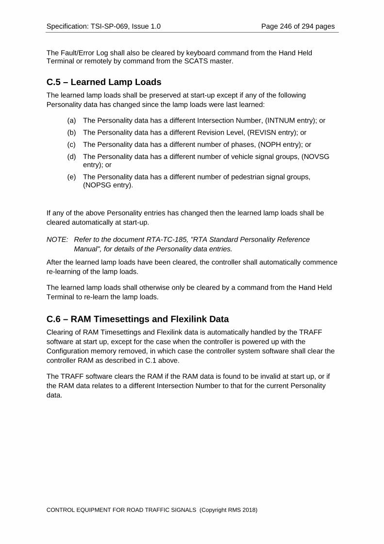
Specification: TSI-SP-069, Issue 1.0 Page 246 of 294 pages
The Fault/Error Log shall also be cleared by keyboard command from the Hand Held Terminal or remotely by command from the SCATS master.
C.5 – Learned Lamp Loads The learned lamp loads shall be preserved at start-up except if any of the following Personality data has changed since the lamp loads were last learned:
(a) The Personality data has a different Intersection Number, (INTNUM entry); or
(b) The Personality data has a different Revision Level, (REVISN entry); or
(c) The Personality data has a different number of phases, (NOPH entry); or
(d) The Personality data has a different number of vehicle signal groups, (NOVSG entry); or
(e) The Personality data has a different number of pedestrian signal groups, (NOPSG entry).
If any of the above Personality entries has changed then the learned lamp loads shall be cleared automatically at start-up.
NOTE: Refer to the document RTA-TC-185, "RTA Standard Personality Reference Manual", for details of the Personality data entries.
After the learned lamp loads have been cleared, the controller shall automatically commence re-learning of the lamp loads.
The learned lamp loads shall otherwise only be cleared by a command from the Hand Held Terminal to re-learn the lamp loads.
C.6 – RAM Timesettings and Flexilink Data Clearing of RAM Timesettings and Flexilink data is automatically handled by the TRAFF software at start up, except for the case when the controller is powered up with the Configuration memory removed, in which case the controller system software shall clear the controller RAM as described in C.1 above.
The TRAFF software clears the RAM if the RAM data is found to be invalid at start up, or if the RAM data relates to a different Intersection Number to that for the current Personality data.
CONTROL EQUIPMENT FOR ROAD TRAFFIC SIGNALS (Copyright RMS 2018)

Specification: TSI-SP-069, Issue 1.0 Page 247 of 294 pages
APPENDIX D
VIRTUAL MACHINE
CONTROL EQUIPMENT FOR ROAD TRAFFIC SIGNALS (Copyright RMS 2018)

Specification: TSI-SP-069, Issue 1.0 Page 248 of 294 pages
APPENDIX D VIRTUAL MACHINE
D.1 – Virtual Machine The following drawing does not form part of this specification, but is included to provide a simplified pictorial overview. The Virtual Machine drawing provides a software view of the controller hardware. The drawing identifies the hardware that the TRAFF software expects to be provided. The Run-Time Library specifies the interface functions to the hardware.
CONTROL EQUIPMENT FOR ROAD TRAFFIC SIGNALS (Copyright RMS 2018)

Specification: TSI-SP-069, Issue 1.0 Page 249 of 294 pages
APPENDIX E
FOURIER SERIES FOR PHASE CONTROL
CONTROL EQUIPMENT FOR ROAD TRAFFIC SIGNALS (Copyright RMS 2018)

Specification: TSI-SP-069, Issue 1.0 Page 250 of 294 pages
APPENDIX E FOURIER SERIES FOR PHASE CONTROL
E.1 – Fourier Series for General Case
The expressions given below are for a sinusoidal waveform, f(x) = sin(x), with phase control applied symmetrically to both positive and negative half-cycles. For the general case the firing angle is α radians after the zero crossing for both half-cycles, ie the conduction angle is (π-α).
The Fourier series for a phase controlled sinusoidal waveform, with for both positive and negative half-cycles, with firing angle α radians is:
[ ] xkkkkkk
xxxf
k)12cos()12sin(sin)12()12cos(cos1
)1(21
cos)2
2cos1(sin)2
2sin22()(
1+++−+−
+
+−
−+−
=
∑∞
=
ααααπ
πα
πααπ
E.2 – Fourier Series for Trivial Cases For the special case of α = 0, ie no phase control, the series reduces to f(x) = sinx.
For the special case of α = π, ie maximum phase control, which results in no conduction angle, the series reduces to f(x) = 0.
E.3 – Fourier Series for the Particular Case of α = π/2 For the particular case of α = π/2, ie half power phase control, the series reduces to:
[ ]f x xk
k x k xk
( ) sin( )
cos( ) cos( )= +−
− − + −=
∞
∑21
2 14 3 4 1
1 π
which expands to the series:
f x x x x x x x x x( ) sin cos cos cos cos cos cos11 cos13 ...= − + − + − + − +2
3 53
73
95 5 7π π π π π π π
CONTROL EQUIPMENT FOR ROAD TRAFFIC SIGNALS (Copyright RMS 2018)
Specification: TSI-SP-069, Issue 1.0 Page 251 of 294 pages
APPENDIX F
LOGIC MODULE CONNECTOR PINOUT SUMMARY
CONTROL EQUIPMENT FOR ROAD TRAFFIC SIGNALS (Copyright RMS 2018)

Specification: TSI-SP-069, Issue 1.0 Page 252 of 294 pages
APPENDIX F LOGIC MODULE CONNECTOR PINOUT SUMMARY
F.1 – XA, XB, XC, XD, XAA, XBB, XCC, XDD Signal Group Outputs Connectors for Signal Group Outputs 1-32 (Clause 6.5.3).
The pin functions for the connectors XA, XB, XC, XD shall be as follows:
Connector Pin XA XB XC XD
1 SG1 Green SG5 Green SG9 Green SG13 Green 2 SG1 Yellow SG5 Yellow SG9 Yellow SG13 Yellow 3 SG1 Red SG5 Red SG9 Red SG13 Red 4 SG2 Green SG6 Green SG10 Green SG14 Green 5 SG2 Yellow SG6 Yellow SG10 Yellow SG14 Yellow 6 SG2 Red SG6 Red SG10 Red SG14 Red 7 SG3 Green SG7 Green SG11 Green SG15 Green 8 SG3 Yellow SG7 Yellow SG11 Yellow SG15 Yellow 9 SG3 Red SG7 Red SG11 Red SG15 Red 10 SG4 Green SG8 Green SG12 Green SG16 Green 11 SG4 Yellow SG8 Yellow SG12 Yellow SG16 Yellow 12 SG4 Red SG8 Red SG12 Red SG16 Red 13 Coding Coding Coding Coding 14 Coding Coding Coding Coding 15 Coding Coding Coding Coding
Table F.1a The pin functions for the connectors XAA, XBB, XCC, XDD shall be as follows:
Connector Pin XAA XBB XCC XDD
1 SG17 Green SG21 Green SG25 Green SG29 Green 2 SG17 Yellow SG21 Yellow SG25 Yellow SG29 Yellow 3 SG17 Red SG21 Red SG25 Red SG29 Red 4 SG18 Green SG22 Green SG26 Green SG30 Green 5 SG18 Yellow SG22 Yellow SG26 Yellow SG30 Yellow 6 SG18 Red SG22 Red SG26 Red SG30 Red 7 SG19 Green SG23 Green SG27 Green SG31 Green 8 SG19 Yellow SG23 Yellow SG27 Yellow SG31 Yellow 9 SG19 Red SG23 Red SG27 Red SG31 Red 10 SG20 Green SG24 Green SG28 Green SG32 Green 11 SG20 Yellow SG24 Yellow SG28 Yellow SG32 Yellow 12 SG20 Red SG24 Red SG28 Red SG32 Red 13 Coding Coding Coding Coding 14 Coding Coding Coding Coding 15 Coding Coding Coding Coding
Table F.1b
CONTROL EQUIPMENT FOR ROAD TRAFFIC SIGNALS (Copyright RMS 2018)

Specification: TSI-SP-069, Issue 1.0 Page 253 of 294 pages
The coding diodes in the wander lead connectors for the signal group outputs shall be as follows:
Connector Coding Diode 1 Coding Diode 2 Anode Cathode Anode Cathode
XA 13 14 XB 14 13 XC 15 14 XD 14 15 XAA 13 15 XBB 15 13 XCC 13 14 15 14 XDD 14 13 14 15
Table F.1c
F.2 – XDS Vehicle Detection System Connector for Vehicle Detection System (Clause 6.5.22).
Serial port, 15 Pin Female Miniature "D" Connector EIA 485.
The pin functions for the connector (XDS) shall be as follows:
Pin Function 1 Tx Data+ 2 Logic Common 3 Tx Clock+ 4 Logic Common 5 Rx Data+ 6 Logic Common 7 Rx Clock+ 8 Logic Common 9 Tx Data- 10 Connector sensing (Note 1) 11 Tx Clock- 12 Ground (Note 2) 13 Rx Data- 14 Reserved 15 Rx Clock-
Table F.2 Note 1:
The NEMA TS2 Specification uses pin 10 to disable the communications port when this pin is connected to Logic Common. This Specification uses pin 10 for sensing that the connector is mated when the pin is connected to Logic Common.
Note 2:
The Ground connection at pin 12 is a safety ground, and must not be connected to the Logic Common, either in the Logic Module circuits or in the mating connector.
CONTROL EQUIPMENT FOR ROAD TRAFFIC SIGNALS (Copyright RMS 2018)
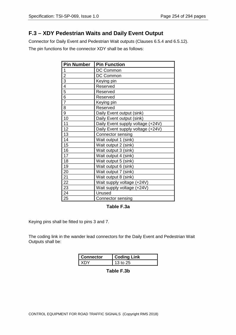
Specification: TSI-SP-069, Issue 1.0 Page 254 of 294 pages
F.3 – XDY Pedestrian Waits and Daily Event Output Connector for Daily Event and Pedestrian Wait outputs (Clauses 6.5.4 and 6.5.12).
The pin functions for the connector XDY shall be as follows:
Pin Number Pin Function 1 DC Common 2 DC Common 3 Keying pin 4 Reserved 5 Reserved 6 Reserved 7 Keying pin 8 Reserved 9 Daily Event output (sink) 10 Daily Event output (sink) 11 Daily Event supply voltage (+24V) 12 Daily Event supply voltage (+24V) 13 Connector sensing 14 Wait output 1 (sink) 15 Wait output 2 (sink) 16 Wait output 3 (sink) 17 Wait output 4 (sink) 18 Wait output 5 (sink) 19 Wait output 6 (sink) 20 Wait output 7 (sink) 21 Wait output 8 (sink) 22 Wait supply voltage (+24V) 23 Wait supply voltage (+24V) 24 Unused 25 Connector sensing
Table F.3a
Keying pins shall be fitted to pins 3 and 7.
The coding link in the wander lead connectors for the Daily Event and Pedestrian Wait Outputs shall be:
Connector Coding Link XDY 13 to 25
Table F.3b
CONTROL EQUIPMENT FOR ROAD TRAFFIC SIGNALS (Copyright RMS 2018)
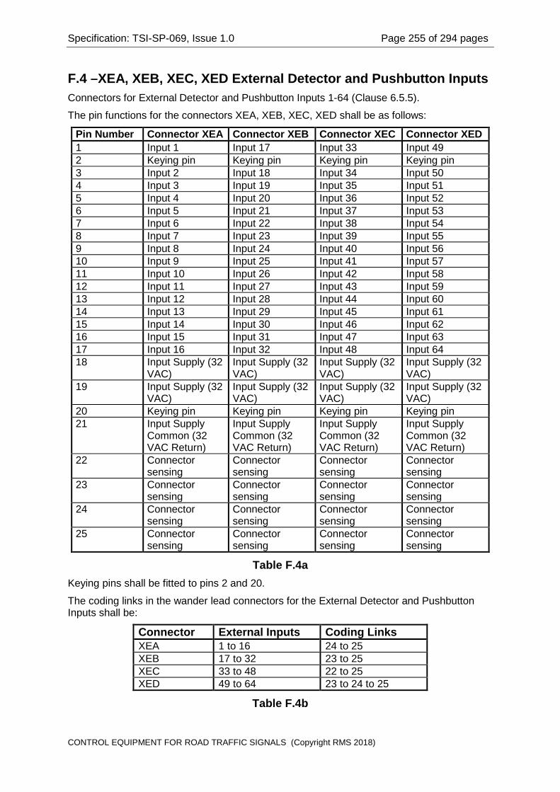
Specification: TSI-SP-069, Issue 1.0 Page 255 of 294 pages
F.4 –XEA, XEB, XEC, XED External Detector and Pushbutton Inputs Connectors for External Detector and Pushbutton Inputs 1-64 (Clause 6.5.5).
The pin functions for the connectors XEA, XEB, XEC, XED shall be as follows:
Pin Number Connector XEA Connector XEB Connector XEC Connector XED 1 Input 1 Input 17 Input 33 Input 49 2 Keying pin Keying pin Keying pin Keying pin 3 Input 2 Input 18 Input 34 Input 50 4 Input 3 Input 19 Input 35 Input 51 5 Input 4 Input 20 Input 36 Input 52 6 Input 5 Input 21 Input 37 Input 53 7 Input 6 Input 22 Input 38 Input 54 8 Input 7 Input 23 Input 39 Input 55 9 Input 8 Input 24 Input 40 Input 56 10 Input 9 Input 25 Input 41 Input 57 11 Input 10 Input 26 Input 42 Input 58 12 Input 11 Input 27 Input 43 Input 59 13 Input 12 Input 28 Input 44 Input 60 14 Input 13 Input 29 Input 45 Input 61 15 Input 14 Input 30 Input 46 Input 62 16 Input 15 Input 31 Input 47 Input 63 17 Input 16 Input 32 Input 48 Input 64 18 Input Supply (32
VAC) Input Supply (32 VAC)
Input Supply (32 VAC)
Input Supply (32 VAC)
19 Input Supply (32 VAC)
Input Supply (32 VAC)
Input Supply (32 VAC)
Input Supply (32 VAC)
20 Keying pin Keying pin Keying pin Keying pin 21 Input Supply
Common (32 VAC Return)
Input Supply Common (32 VAC Return)
Input Supply Common (32 VAC Return)
Input Supply Common (32 VAC Return)
22 Connector sensing
Connector sensing
Connector sensing
Connector sensing
23 Connector sensing
Connector sensing
Connector sensing
Connector sensing
24 Connector sensing
Connector sensing
Connector sensing
Connector sensing
25 Connector sensing
Connector sensing
Connector sensing
Connector sensing
Table F.4a Keying pins shall be fitted to pins 2 and 20.
The coding links in the wander lead connectors for the External Detector and Pushbutton Inputs shall be:
Connector External Inputs Coding Links XEA 1 to 16 24 to 25 XEB 17 to 32 23 to 25 XEC 33 to 48 22 to 25 XED 49 to 64 23 to 24 to 25
Table F.4b
CONTROL EQUIPMENT FOR ROAD TRAFFIC SIGNALS (Copyright RMS 2018)

Specification: TSI-SP-069, Issue 1.0 Page 256 of 294 pages
F.5 –XHHT Hand Held Terminal Logic Module connector for Hand Held Terminal user interface (Clause 6.5.25).
Serial port, 9 Pin Male Miniature "D" Connector (DTE connections).
The pin functions for the connector XHHT shall be as follows:
Pin Number Pin Name Pin Function Signal Direction
1 - Unused - 2 RxD Received Data In 3 TxD Transmitted Data Out 4 +12V Supply to HHT Out 5 Common Signal Common - 6 DSR Data Set Ready In 7 RTS Request To Send Out 8 CTS Clear To Send In 9 - Unused -
Table F.5
NOTE: The supply for the HHT at pins 4 and 5 shall be able to source 85 mA and shall be current limited to protect against overload.
CONTROL EQUIPMENT FOR ROAD TRAFFIC SIGNALS (Copyright RMS 2018)

Specification: TSI-SP-069, Issue 1.0 Page 257 of 294 pages
F.6 – XID Site Identification Encoder Connector for the Site Identification Encoder (Clause 6.5.19).
The pin functions for the connector XID shall be as follows:
Pin Function 1 No connection 2 Data Line 7 3 Data Line 4 4 Data Line 1 5 Select Line 7 6 Select Line 4 7 Select Line 1 8 Electronic Facility Switch Tx to Logic 9 Gas Sensor Signal (V-) input 10 Light Sensor (V-) input 11 Light Sensor (V+) input 12 Auxiliary Relay Drive (V-) 13 Auxiliary Relay Drive (V+) 14 Master Relay Drive (V-) 15 Master Relay Drive (V+) 16 No connection Dimming Control 2 17 No connection Dimming Control 1 18 Data Line 6 19 Data Line 3 20 Data Line 0 21 Select Line 6 22 Select Line 3 23 Select Line 0 24 Electronic Facility Switch Tx from Logic 25 Gas Sensor Signal (V+) input 26 Gas Sensor Supply (V+) 27 Reserved Control Panel LED Supply (V+) 28 Residual Direct Current Fault input 29 Flash Change-over Relay Status input 30 Flash Disable output 31 No connection Dimming Monitor Signal 32 Logic common 33 Data Line 5 34 Data Line 2 35 Logic common 36 Select Line 5 37 Select Line 2 38 Logic common 39 Logic common 40 Logic common 41 No connection 42 Reserved Control Panel Common 43 Reserved Control Panel LED Strobe B 44 Reserved Control Panel LED Strobe A
Table F.6
CONTROL EQUIPMENT FOR ROAD TRAFFIC SIGNALS (Copyright RMS 2018)

Specification: TSI-SP-069, Issue 1.0 Page 258 of 294 pages
F.7 –XLD, XLL, XLX, XLY Detector Loops 1-64 Connectors for Loop Detector Sensor Loops (Clause 6.5.16).
The pin functions for the connectors XLD, XLL, XLX and XLY shall be as follows:
Pin Function 1 Ground 2 Channel 1 Loop 3 Channel 2 Loop 4 Channel 3 Loop 5 Channel 4 Loop 6 Channel 5 Loop 7 Channel 6 Loop 8 Channel 7 Loop 9 Channel 8 Loop 10 Channel 9 Loop 11 Channel 10 Loop 12 Channel 11 Loop 13 Channel 12 Loop 14 Channel 13 Loop 15 Channel 14 Loop 16 Channel 15 Loop 17 Channel 16 Loop 18 Connector sensing 19 Connector sensing 20 Channel 1 Loop 21 Channel 2 Loop 22 Channel 3 Loop 23 Channel 4 Loop 24 Channel 5 Loop 25 Channel 6 Loop 26 Channel 7 Loop 27 Channel 8 Loop 28 Channel 9 Loop 29 Channel 10 Loop 30 Channel 11 Loop 31 Channel 12 Loop 32 Channel 13 Loop 33 Channel 14 Loop 34 Channel 15 Loop 35 Channel 16 Loop 36 Connector sensing 37 Ground
Table F.7a
CONTROL EQUIPMENT FOR ROAD TRAFFIC SIGNALS (Copyright RMS 2018)
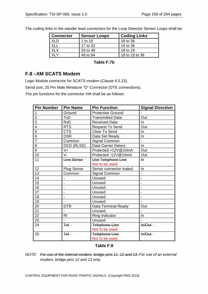
Specification: TSI-SP-069, Issue 1.0 Page 259 of 294 pages
The coding links in the wander lead connectors for the Loop Detector Sensor Loops shall be:
Connector Sensor Loops Coding Links XLD 1 to 16 18 to 36 XLL 17 to 32 19 to 36 XLX 33 to 48 18 to 19 XLY 49 to 64 18 to 19 to 36
Table F.7b
F.8 –XM SCATS Modem Logic Module connector for SCATS modem (Clause 6.5.23).
Serial port, 25 Pin Male Miniature "D" Connector (DTE connections).
The pin functions for the connector XM shall be as follows:
Pin Number Pin Name Pin Function Signal Direction 1 Ground Protective Ground - 2 TxD Transmitted Data Out 3 RxD Received Data In 4 RTS Request To Send Out 5 CTS Clear To Send In 6 DSR Data Set Ready In 7 Common Signal Common - 8 DCD (RLSD) Data Carrier Detect In 9 V+ Protected +12V@10mA Out 10 V- Protected -12V@10mA Out 11 Line Sense - Use Telephone Line
Not to be used In
12 Plug Sense Sense connector mated In 13 Common Signal Common - 14 - Unused - 15 - Unused - 16 - Unused - 17 - Unused - 18 - Unused - 19 - Unused - 20 DTR Data Terminal Ready Out 21 - Unused - 22 RI Ring Indicator In 23 - Unused - 24 Tel - Telephone Line
Not to be used In/Out -
25 Tel - Telephone Line Not to be used
In/Out -
Table F.8
NOTE: For use of the internal modem, bridge pins 11, 12 and 13. For use of an external modem, bridge pins 12 and 13 only.
CONTROL EQUIPMENT FOR ROAD TRAFFIC SIGNALS (Copyright RMS 2018)

Specification: TSI-SP-069, Issue 1.0 Page 260 of 294 pages
F.9 – XP Logic Module Power Connector
The pin functions for connector XP (Clause 6.10.4.2), shall be as follows:
Pin Function 1 Earth (Long Pin) 2 Lamp Active Supply 3 Lamp Active Supply 4 Lamp Neutral 5 Lamp Active Supply 6 Lamp Active Supply 7 Logic Neutral 8 No connection 9 Logic Active Supply 10 32 V r.m.s. ELV Supply 11 32 V r.m.s. ELV Supply (Common) 12 Earth (Long Pin)
Table F.9
There is no requirement for a sensing link in connector XP.
CONTROL EQUIPMENT FOR ROAD TRAFFIC SIGNALS (Copyright RMS 2018)

Specification: TSI-SP-069, Issue 1.0 Page 261 of 294 pages
F.10 – XSF Special Facility Inputs and Outputs 1-12
Connector for Special Facility Inputs and Outputs 1 12 (Clause 6.5.13).
The pin functions for the connector XSF shall be as follows:
Pin Function 1 Special Facility input 1 2 Special Facility input 2 3 Special Facility input 3 4 Special Facility input 4 5 Special Facility input 5 6 Special Facility input 6 7 Special Facility input 7 8 Special Facility input 8 9 DC Common 10 DC Common 11 Special Facility output 1 12 Special Facility output 2 13 Special Facility output 3 14 Special Facility output 4 15 Special Facility output 5 16 Special Facility output 6 17 Special Facility output 7 18 Special Facility output 8 19 Keying pin 20 Keying pin 21 Input Supply (32 VAC) 22 Input Supply (32 VAC Common) 23 Special Facility input 9 24 Special Facility input 10 25 Special Facility input 11 26 Special Facility input 12 27 Connector sensing 28 Connector sensing 29 Connector sensing 30 Special Facility output 9 31 Special Facility output 10 32 Special Facility output 11 33 Special Facility output 12 34 Output Supply (+24V) 35 Output Supply (+24V) 36 Output Supply (+24V) 37 Output Supply (+24V)
Table F.10a
Keying pins shall be fitted to pins 19 and 20.
CONTROL EQUIPMENT FOR ROAD TRAFFIC SIGNALS (Copyright RMS 2018)

Specification: TSI-SP-069, Issue 1.0 Page 262 of 294 pages
The coding links in the wander lead connectors for the Special Facility Inputs and Outputs 1 12 shall be:
Connector Special Facilities Coding Links XSF 1 to 12 28 to 29
Table F.10b
F.11 – XTSA, XTSB Intelligent Transportation Systems Ports 1-2
Logic Module connector for ITS serial ports 1 and 2 (Clause 6.5.26).
Serial port, 15 Pin Male Miniature "D" Connector (DTE connections) EIA 232.
The pin functions for the connectors XTSA and XTSB shall be as follows:
Pin Number Pin Name Pin Function Signal Direction 1 Ground Protective Ground - 2 TxD Transmitted Data Out 3 RxD Received Data In 4 RTS Request To Send Out 5 CTS Clear To Send In 6 DSR Data Set Ready In 7 Common Signal Common - 8 DCD (RLSD) Data Carrier Detect In 9 - Unused - 10 - Unused - 11 Plug Sense Sense Port 1 - 12 Plug Sense Sense common - 13 Plug Sense Sense Port 2 - 14 DTR Data Terminal Ready Out 15 RI Ring Indicator In
Table F.11
CONTROL EQUIPMENT FOR ROAD TRAFFIC SIGNALS (Copyright RMS 2018)

Specification: TSI-SP-069, Issue 1.0 Page 263 of 294 pages
F.12 – XTSC, XTSD Intelligent Transportation Systems Ports 3-4
Logic Module connector for ITS serial ports 3 and 4 (Clause 6.5.26).
Serial port, 15 Pin Female Miniature Double Density "D" Connector EIA 485.
The pin functions for the connectors XTSC and XTSD shall be as follows:
Pin Number Pin Name Pin Function Signal Direction
1 TxD (B+) Transmitted Data Out 2 TxD (A-) Transmitted Data Out 3 Plug sense Sense Port 3 - 4 RxD (B+) Received Data In 5 RxD (A-) Received Data In 6 RTS (B+) Request To Send Out 7 RTS (A-) Request To Send Out 8 Plug sense Common - 9 CTS (B+) Clear To Send In 10 CTS (A-) Clear To Send In 11 TxClock(B+) Transmit Clock Out 12 TxClock(A-) Transmit Clock Out 13 Plug sense Sense Port 4 - 14 RxClock(B+) Receive Clock In 15 RxClock(A-) Receive Clock In
Table F.12
NOTE: For EIA 485 operation with a single pair, pins 1 and 2 are used for Transmit and Receive on the tri state bus.
CONTROL EQUIPMENT FOR ROAD TRAFFIC SIGNALS (Copyright RMS 2018)

Specification: TSI-SP-069, Issue 1.0 Page 264 of 294 pages
F.13 – XTTY SCATS Portable Terminal
Logic Module connector for SCATS portable terminal (Clause 6.5.24).
Serial port, 25 Pin Female Miniature "D" Connector (DCE Connections, not DTE).
The pin functions for the connector XTTY shall be as follows:
Pin Number Pin Name Pin Function Signal Direction 1 Ground Protective Ground - 2 TxD Transmitted Data In 3 RxD Received Data Out 4 RTS Request To Send In 5 CTS Clear To Send Out 6 DSR Data Set Ready Out 7 Common Signal Common - 8 DCD (RLSD) Data Carrier Detect Out 9 V+ Protected +12V@10mA Out 10 V- Protected -12V@10mA Out 11 - Unused - 12 - Unused - 13 - Unused - 14 - Unused - 15 - Unused - 16 - Unused - 17 - Unused - 18 - Unused - 19 - Unused - 20 DTR Data Terminal Ready In 21 - Unused - 22 - Unused - 23 - Unused - 24 - Unused - 25 - Unused -
Table F.13
CONTROL EQUIPMENT FOR ROAD TRAFFIC SIGNALS (Copyright RMS 2018)

Specification: TSI-SP-069, Issue 1.0 Page 265 of 294 pages
F.14 – XXF Special Facility inputs and Outputs 13-24
Connector for Special Facility Inputs and Outputs 13 24 (Clause 6.5.13).
The pin functions for the connector XXF shall be as follows:
Pin Function 1 Special Facility input 13 2 Special Facility input 14 3 Special Facility input 15 4 Special Facility input 16 5 Special Facility input 17 6 Special Facility input 18 7 Special Facility input 19 8 Special Facility input 20 9 DC Common 10 DC Common 11 Special Facility output 13 12 Special Facility output 14 13 Special Facility output 15 14 Special Facility output 16 15 Special Facility output 17 16 Special Facility output 18 17 Special Facility output 19 18 Special Facility output 20 19 Keying pin 20 Keying pin 21 Input Supply (32 VAC) 22 Input Supply (32 VAC Common) 23 Special Facility input 21 24 Special Facility input 22 25 Special Facility input 23 26 Special Facility input 24 27 Connector sensing 28 Connector sensing 29 Connector sensing 30 Special Facility output 21 31 Special Facility output 22 32 Special Facility output 23 33 Special Facility output 24 34 Output Supply (+24V) 35 Output Supply (+24V) 36 Output Supply (+24V) 37 Output Supply (+24V)
Table F.14a
Keying pins shall be fitted to pins 19 and 20.
CONTROL EQUIPMENT FOR ROAD TRAFFIC SIGNALS (Copyright RMS 2018)

Specification: TSI-SP-069, Issue 1.0 Page 266 of 294 pages
The coding links in the wander lead connectors for the Special Facility Inputs and Outputs 13 - 24 shall be:
Connector Special Facilities Coding Links XXF 13 to 24 27 to 29
Table F.14b
CONTROL EQUIPMENT FOR ROAD TRAFFIC SIGNALS (Copyright RMS 2018)

Specification: TSI-SP-069, Issue 1.0 Page 267 of 294 pages
F.15 – XVP Minor Linking
Connector for Minor Linking Inputs and Outputs (Clause 6.5.14).
The pin functions for the connector XVP shall be as follows:
Pin Function 1 Minor Linking input 1+ 2 Minor Linking input 2+ 3 Minor Linking input 3+ 4 Minor Linking input 4+ 5 Minor Linking input 5+ 6 Minor Linking input 6+ 7 Reserved for spare input 7+ 8 Keying pin 9 Unused 10 Unused 11 Unused 12 Unused 13 Minor Linking output 1+ 14 Minor Linking output 2+ 15 Minor Linking output 3+ 16 Minor Linking output 4+ 17 Minor Linking output 5+ 18 Minor Linking output 6+ 19 Minor Linking output 7+ 20 Minor Linking input 1- 21 Minor Linking input 2- 22 Minor Linking input 3- 23 Minor Linking input 4- 24 Minor Linking input 5- 25 Minor Linking input 6- 26 Reserved for spare input 7- 27 Connector sensing 28 Connector sensing 29 Unused 30 Keying pin 31 Minor Linking output 1- 32 Minor Linking output 2- 33 Minor Linking output 3- 34 Minor Linking output 4- 35 Minor Linking output 5- 36 Minor Linking output 6- 37 Minor Linking output 7-
Table F.15a
Keying pins shall be fitted to pins 8 and 30.
CONTROL EQUIPMENT FOR ROAD TRAFFIC SIGNALS (Copyright RMS 2018)
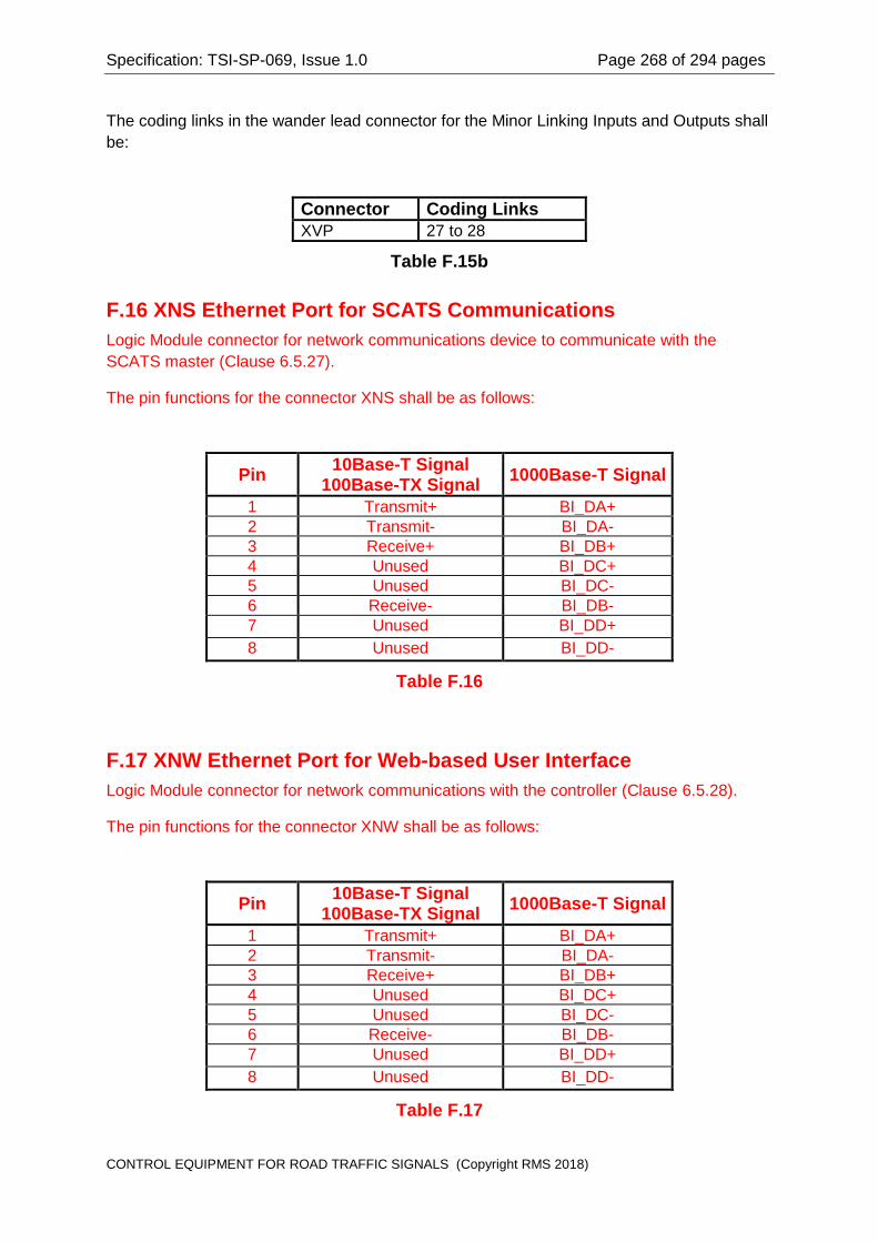
Specification: TSI-SP-069, Issue 1.0 Page 268 of 294 pages
The coding links in the wander lead connector for the Minor Linking Inputs and Outputs shall be:
Connector Coding Links XVP 27 to 28
Table F.15b
F.16 XNS Ethernet Port for SCATS Communications Logic Module connector for network communications device to communicate with the SCATS master (Clause 6.5.27).
The pin functions for the connector XNS shall be as follows:
Pin 10Base-T Signal 100Base-TX Signal 1000Base-T Signal
1 Transmit+ BI_DA+ 2 Transmit- BI_DA- 3 Receive+ BI_DB+ 4 Unused BI_DC+ 5 Unused BI_DC- 6 Receive- BI_DB- 7 Unused BI_DD+ 8 Unused BI_DD-
Table F.16
F.17 XNW Ethernet Port for Web-based User Interface Logic Module connector for network communications with the controller (Clause 6.5.28).
The pin functions for the connector XNW shall be as follows:
Pin 10Base-T Signal 100Base-TX Signal 1000Base-T Signal
1 Transmit+ BI_DA+ 2 Transmit- BI_DA- 3 Receive+ BI_DB+ 4 Unused BI_DC+ 5 Unused BI_DC- 6 Receive- BI_DB- 7 Unused BI_DD+ 8 Unused BI_DD-
Table F.17
CONTROL EQUIPMENT FOR ROAD TRAFFIC SIGNALS (Copyright RMS 2018)
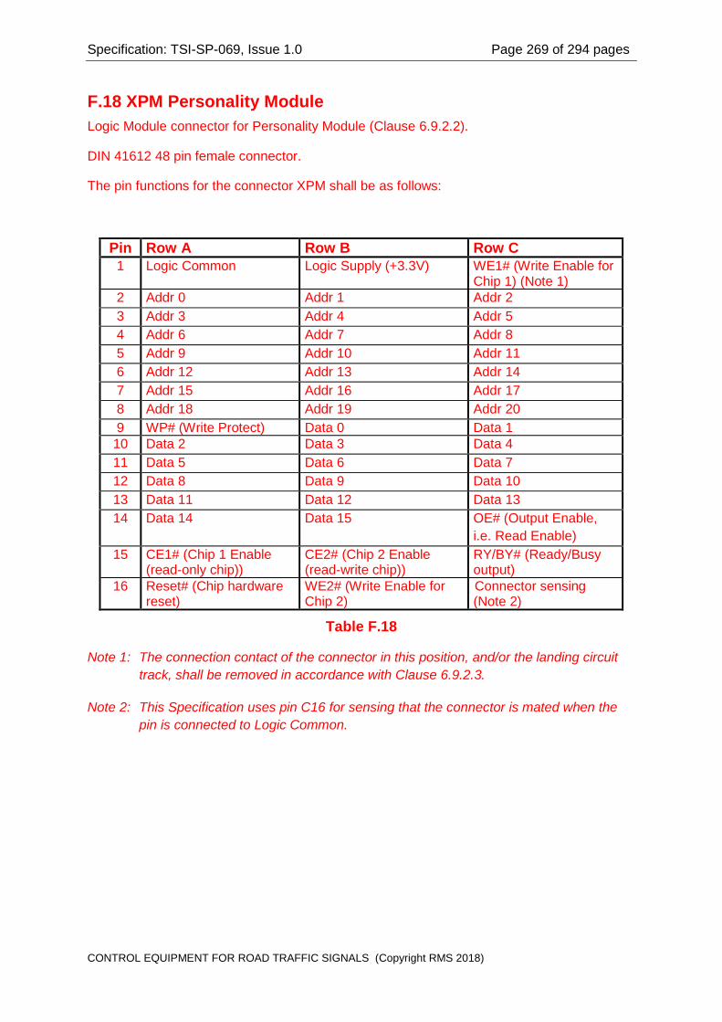
Specification: TSI-SP-069, Issue 1.0 Page 269 of 294 pages
F.18 XPM Personality Module Logic Module connector for Personality Module (Clause 6.9.2.2).
DIN 41612 48 pin female connector.
The pin functions for the connector XPM shall be as follows:
Pin Row A Row B Row C 1 Logic Common Logic Supply (+3.3V) WE1# (Write Enable for
Chip 1) (Note 1) 2 Addr 0 Addr 1 Addr 2 3 Addr 3 Addr 4 Addr 5 4 Addr 6 Addr 7 Addr 8 5 Addr 9 Addr 10 Addr 11 6 Addr 12 Addr 13 Addr 14 7 Addr 15 Addr 16 Addr 17 8 Addr 18 Addr 19 Addr 20 9 WP# (Write Protect) Data 0 Data 1 10 Data 2 Data 3 Data 4 11 Data 5 Data 6 Data 7 12 Data 8 Data 9 Data 10 13 Data 11 Data 12 Data 13 14 Data 14 Data 15 OE# (Output Enable,
i.e. Read Enable) 15 CE1# (Chip 1 Enable
(read-only chip)) CE2# (Chip 2 Enable (read-write chip))
RY/BY# (Ready/Busy output)
16 Reset# (Chip hardware reset)
WE2# (Write Enable for Chip 2)
Connector sensing (Note 2)
Table F.18
Note 1: The connection contact of the connector in this position, and/or the landing circuit track, shall be removed in accordance with Clause 6.9.2.3.
Note 2: This Specification uses pin C16 for sensing that the connector is mated when the pin is connected to Logic Common.
CONTROL EQUIPMENT FOR ROAD TRAFFIC SIGNALS (Copyright RMS 2018)

Specification: TSI-SP-069, Issue 1.0 Page 270 of 294 pages
F.19 XRJ PSTN Modem Logic Module connector for PSTN modem (Clause 6.5.23).
Modular connector 6P2C (RJ11) connector socket.
The pin functions for the connector XRJ shall be as follows:
Pin Function 1 Unused 2 Unused 3 Telephone Line 4 Telephone Line 5 Unused 6 Unused
Table F.19
F.20 XUP USB Port for User Interface Logic Module connector for user interface (Clause 6.5.29).
The pin functions for the connector XUP shall be as follows:
Pin Function 1 V BUS (+5V) 2 D- 3 D+ 4 Ground
Table F.20
CONTROL EQUIPMENT FOR ROAD TRAFFIC SIGNALS (Copyright RMS 2018)

Specification: TSI-SP-069, Issue 1.0 Page 271 of 294 pages
APPENDIX G
WIRED HOUSING CONNECTOR PINOUT SUMMARY
CONTROL EQUIPMENT FOR ROAD TRAFFIC SIGNALS (Copyright RMS 2018)

Specification: TSI-SP-069, Issue 1.0 Page 272 of 294 pages
APPENDIX G WIRED HOUSING CONNECTOR PINOUT SUMMARY
G.1 – Site Identification Encoder Unit Connectors(Clause 7.13)
G.1.1 Connector ZDR for Door Switch (Clause 7.13.10)
The pin functions for connector ZDR shall be as follows:
Pin Number Circuit Connection 1 Connector sensing loop (Select line) 2 Door Switch 3 Door Switch 4 Connector sensing loop (Sense line)
Table G.1.1
The wander lead connector shall have a link bridging pins 1 and 4 to allow the logic circuits to sense that the connector has been mated.
G.1.2 Connector ZFL for Flasher Unit (Clause 7.13.6) The pin functions for connector ZFL shall be as follows:
Pin Function 1 Logic Common 2 Flash Disable Control Signal 3 Flash Change-over Relay Status Signal 4 Residual Direct Current Fault Signal 5 Logic Common 6 Facility Switch Disable Flasher 7 Connector sensing loop (Sense line) 8 Connector sensing loop (Select line)
Table G.1.2 Refer to Clause 7.13.6 for the requirements for sensing the mating of the wander lead connector.
CONTROL EQUIPMENT FOR ROAD TRAFFIC SIGNALS (Copyright RMS 2018)
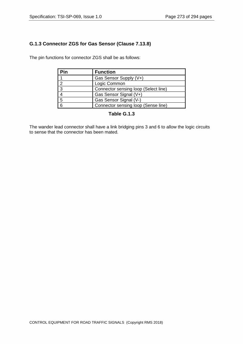
Specification: TSI-SP-069, Issue 1.0 Page 273 of 294 pages
G.1.3 Connector ZGS for Gas Sensor (Clause 7.13.8) The pin functions for connector ZGS shall be as follows:
Pin Function 1 Gas Sensor Supply (V+) 2 Logic Common 3 Connector sensing loop (Select line) 4 Gas Sensor Signal (V+) 5 Gas Sensor Signal (V-) 6 Connector sensing loop (Sense line)
Table G.1.3 The wander lead connector shall have a link bridging pins 3 and 6 to allow the logic circuits to sense that the connector has been mated.
CONTROL EQUIPMENT FOR ROAD TRAFFIC SIGNALS (Copyright RMS 2018)

Specification: TSI-SP-069, Issue 1.0 Page 274 of 294 pages
G.1.4 Connector ZID for Logic Module (Clause 7.13.11)
Pin Function 1 No connection 2 Data Line 7 3 Data Line 4 4 Data Line 1 5 Select Line 7 6 Select Line 4 7 Select Line 1 8 Electronic Facility Switch Tx to Logic 9 Gas Sensor Signal (V-) 10 Light Sensor (V-) 11 Light Sensor (V+) 12 Auxiliary Relay Drive (V-) 13 Auxiliary Relay Drive (V+) 14 Master Relay Drive (V-) 15 Master Relay Drive (V+) 16 No connection Dimming Control 2 17 No connection Dimming Control 1 18 Data Line 6 19 Data Line 3 20 Data Line 0 21 Select Line 6 22 Select Line 3 23 Select Line 0 24 Electronic Facility Switch Tx from Logic 25 Gas Sensor Signal (V+) 26 Gas Sensor Supply (V+) 27 Reserved Control Panel LED Supply (V+) 28 Residual Direct Current Fault 29 Flash Change-over Relay Status 30 Flash Disable 31 No connection Dimming Monitor Signal 32 Logic common 33 Data Line 5 34 Data Line 2 35 Logic common 36 Select Line 5 37 Select Line 2 38 Logic common 39 Logic common 40 Logic common 41 No connection 42 Reserved Control Panel Common 43 Reserved Control Panel LED Strobe B 44 Reserved Control Panel LED Strobe A
Table G.1.4
CONTROL EQUIPMENT FOR ROAD TRAFFIC SIGNALS (Copyright RMS 2018)

Specification: TSI-SP-069, Issue 1.0 Page 275 of 294 pages
There is no sensing link in the wander lead connector. The connector sensing link is provided in the Site Identification Encoder Unit by a diode connecting Data line 3 to Select line 7 to allow the logic circuits to sense that the connector has been mated.
G.1.5 Connector ZLS for Light Sensor (Clause 7.13.7) The pin functions for connector ZLS shall be as follows:
Pin Function 1 Connector sensing loop (Select line) 2 Connector sensing loop (Sense line) 3 Light Sensor (V+) 4 Light Sensor (V-)
Table G.1.5 The wander lead connector shall have a link bridging pins 1 and 2 to allow the logic circuits to sense that the connector has been mated.
G.1.6 Connector ZMR for Master Relay (Clause 7.13.4) The pin functions for connector ZMR shall be as follows:
Pin Number Circuit Connection 1 Auxiliary Relay coil (V+) 2 Auxiliary Relay coil (V-) 3 Connector sensing loop (Select line) 4 Auxiliary Relay contact 5 Auxiliary Relay contact 6 Master Relay coil (V+) 7 Master Relay coil (V-) 8 Connector sensing loop (Sense line) 9 Master Relay contact 10 Master Relay contact
Table G.1.6 The wander lead connector shall have a link bridging pins 3 and 8 to allow the logic circuits to sense that the connector has been mated.
CONTROL EQUIPMENT FOR ROAD TRAFFIC SIGNALS (Copyright RMS 2018)

Specification: TSI-SP-069, Issue 1.0 Page 276 of 294 pages
G.1.7 No Longer Used Connector ZPC Section deleted in Amendment 2 This connector is reserved for future use. The pin functions for connector ZPC shall be as follows:
Pin Function 1 Connector sensing loop (Select line) 2 Connector sensing loop (Sense line) 3 Switch Bank Select 0 4 Switch Bank Select 1 5 LED Strobe A 6 LED Strobe B 7 Common 8 LED supply (V+) 9 Switch Data Line 0
10 Switch Data Line 1 11 Switch Data Line 2 12 Switch Data Line 3 13 Switch Data Line 4 14 Switch Data Line 5 15 Switch Data Line 6 16 Switch Data Line 7
Table G.1.7 The wander lead connector shall have a link bridging pins 1 and 2 to allow the logic circuits to sense that the connector has been mated.
G.1.8 Connector ZSW for Facility Switch (Clause 7.13.5) The pin functions for connector ZSW shall be as follows:
Pin Number Circuit Connection 1 Facility Switch Disable Flasher contact 2 Electronic Facility Switch input 3 Electronic Facility Switch output 4 Common to Electronic Facility Switch 5 Connector sensing loop (Select line) 6 Facility Switch Auxiliary Relay (-) contact 7 Facility Switch Auxiliary Relay (+) contact 8 Facility Switch Disable Flasher contact 9 Facility Switch coding contact A 10 Facility Switch coding contact B 11 Facility Switch coding contact C 12 Connector sensing loop (Sense line) 13 Facility Switch Master Relay (-) contact 14 Facility Switch Master Relay (+) contact
Table G.1.8
CONTROL EQUIPMENT FOR ROAD TRAFFIC SIGNALS (Copyright RMS 2018)

Specification: TSI-SP-069, Issue 1.0 Page 277 of 294 pages
The wander lead connector shall have a link bridging pins 5 and 12 to allow the logic circuits to sense that the connector has been mated. Refer to Clause 7.13.5.
G.1.9 Connector ZHC for Housing Electrical Code Encoder The pin functions for connector ZHC shall be as follows:
Pin Function 1 Read Enable (Select line) 2 Not Used 3 Connector sensing loop (Sense line) 4 Connector sensing loop (Select line) 5 Housing Electrical Code Bit 0 6 Housing Electrical Code Bit 1 7 Housing Electrical Code Bit 2 8 Housing Electrical Code Bit 3
Table G.1.9 The wander lead connector shall have a link bridging pins 3 and 4 to allow the logic circuits to sense that the connector has been mated.
G.1.10 Connector ZDC for Lamp Dimming Signal Generator The pin functions for connector ZDC shall be as follows:
Pin Function 1 Dimming Control 1 2 Dimming Control 2 3 Connector sensing loop (Sense line) 4 Monitor Signal 5 Logic Common 6 Connector sensing loop (Select line)
Table G.1.10 The wander lead connector shall have a link bridging pins 3 and 6 to allow the logic circuits to sense that the connector has been mated.
CONTROL EQUIPMENT FOR ROAD TRAFFIC SIGNALS (Copyright RMS 2018)

Specification: TSI-SP-069, Issue 1.0 Page 278 of 294 pages
G.2 – Flasher Unit Connectors (Clause 7.12)
G.2.1 Connector XFC for Flasher Unit Control (Clause 7.12.12)
The pin functions for connector XFC shall be as follows:
Pin Function 1 Isolated Logic Common 2 Flash Disable Input 3 Flash Change-over Relay Status output 4 Residual Direct Current Fault output 5 Isolated Logic Common 6 Facility Switch Disable Flasher input 7 Reserved 8 Connector Sense Link 9 Connector Sense Link
Table G.2.1 The Flasher Unit provides a link between pins 8 and 9 for sensing that all connectors for the Flasher Unit Control circuits have been mated. The wander lead shall include wires at connector pins 8 and 9 to continue the circuit to the Site Identification Unit for sensing that the connector has been mated.
G.2.2 Connector XFP for Flasher Unit Power (Clause 7.12.13) The pin functions for connector XFP shall be as follows:
Pin Function 1 Earth (Long Pin) 2 Flashing Active Output 1 3 Mains Neutral 4 Flasher Active Input 5 Flasher Active Input 6 Lamp Active Sense Input 7 Flash Change-over Relay Drive Output 8 Flashing Active Output 2 9 Earth (Long Pin)
Table G.2.2 There is no requirement for a sensing link in connector XFP.
CONTROL EQUIPMENT FOR ROAD TRAFFIC SIGNALS (Copyright RMS 2018)

Specification: TSI-SP-069, Issue 1.0 Page 279 of 294 pages
APPENDIX H
CONNECTOR TYPES SUMMARY
CONTROL EQUIPMENT FOR ROAD TRAFFIC SIGNALS (Copyright RMS 2018)

Specification: TSI-SP-069, Issue 1.0 Page 280 of 294 pages
APPENDIX H CONNECTOR TYPES SUMMARY
H.1 – Logic Module Connectors (Clause 6.5)
H.1.1 Connector Types Summary Summary of connectors mounted on the Logic Module:
Connector Label Function Connector Type Pins M/F XA SG1-4 Outputs AMP Mate-N-Lok 350784-1 15 F XB SG5-8 Outputs AMP Mate-N-Lok 350784-1 15 F XC SG9-12 Outputs AMP Mate-N-Lok 350784-1 15 F XD SG13-16 Outputs AMP Mate-N-Lok 350784-1 15 F XAA SG17-20 Outputs AMP Mate-N-Lok 350784-1 15 F XBB SG21-24 Outputs AMP Mate-N-Lok 350784-1 15 F XCC SG25-28 Outputs AMP Mate-N-Lok 350784-1 15 F XDD SG29-32 Outputs AMP Mate-N-Lok 350784-1 15 F XDS V Detection System AMP HD-20 series 15 F XDY Waits & Daily Event AMP HD-20 series 25 F XEA External Input 1-16 AMP HD-20 series 25 F XEB External Input 17-32 AMP HD-20 series 25 F XEC External Input 33-48 AMP HD-20 series 25 F XED External Input 49-64 AMP HD-20 series 25 F XHHT Hand Held Terminal AMP HD-20 series 9 M XID Site ID Encoder AMP HD-22 series 44 F XLD Detector loop 1-16 AMP HD-20 series 37 M XLL Detector loop 17-32 AMP HD-20 series 37 M XM SCATS Modem AMP HD-20 series 25 M XNS SCATS
Communications ISO/IEC 8877 8P8C 8 F
XNW Web-based User Interface
ISO/IEC 8877 8P8C 8 F
XP Logic Module Power AMP Mate-N-Lok 350783-1 12 F XPM Personality Module DIN 41612 48 F XRJ PSTN Modem 6P2C (RJ11) modular socket 4 or 6 F XSF Special Fac 1-12 AMP HD-20 series 37 F XTSA ITS Port 1 AMP HD-20 series 15 M XTSB ITS Port 2 AMP HD-20 series 15 M XTSC ITS Port 3 AMP HD-22 series 15 F XTSD ITS Port 4 AMP HD-22 series 15 F XTTY SCATS Terminal AMP HD-20 series 25 F XUP USB Port USB Series A Receptacle 4 F XXF Special Fac 13-24 AMP HD-20 series 37 F XVP Minor Linking AMP HD-20 series 37 F
Table H.1.1
H.1.2 Logic Module Connectors XA, XB, XC, XD, XAA, XBB, XCC, XDD
CONTROL EQUIPMENT FOR ROAD TRAFFIC SIGNALS (Copyright RMS 2018)
Specification: TSI-SP-069, Issue 1.0 Page 281 of 294 pages
The connectors for signal group outputs shall each be a 15 pin panel mounted connector, AMP "Universal Mate N Lok" 350784-1 for connection to the housing wiring. The socket contacts for the signal group outputs shall be tin plated brass, equivalent to AMP 350536-1 (20 14 AWG wire). The socket contacts for the connector coding diodes shall be gold plated in the contact area, equivalent to AMP 350536-2.
Note that alternative connector types for signal group outputs will not be considered.
The coding diodes shall be silicon signal diodes such as 1N914A.
H.1.3 Logic Module Connector XDS The connector for the Vehicle Detection System shall be a panel mounted 15 way Miniature "D" connector with female contacts, to mate with a connector equivalent to AMP HDP 20 series, part number 205206-3. The connector shall be fitted with front panel threaded latching blocks, equivalent to AMP part number 747080-2.
H.1.4 Logic Module Connector XDY The connector for the Daily Event and Pedestrian Wait outputs shall be a panel mounted 25 way Miniature "D" connector with female contacts, to mate with a connector equivalent to AMP HDP 20 series, part number 207464-2. The connector shall be fitted with front panel threaded latching blocks, equivalent to AMP part number 747080-2.
The keying pins shall be equivalent to AMP part number 206509-1.
H.1.5 Logic Module Connectors XEA, XEB, XEC, XED The connectors for the External Detector and Pushbutton Inputs shall be panel mounted 25 way Miniature "D" connectors with female contacts, to mate with connectors equivalent to AMP HDP 20 series, part number 207464-2. Each connector shall be fitted with front panel threaded latching blocks, equivalent to AMP part number 747080-2.
The keying pins shall be equivalent to AMP part number 206509-1.
H.1.6 Logic Module Connector XHHT The connector for the Hand Held Terminal shall be a panel mounted 9 way Miniature "D" connector with male contacts, to mate with a connector equivalent to AMP HDP 20 series, part number 205203-3. The connector shall be fitted with front panel threaded latching blocks, equivalent to AMP part number 747080-2.
H.1.7 Logic Module Connector XHHT The connector for the Site Identification Encoder shall be a panel mounted 44 way Miniature Double Density "D" connector with female contacts, to mate with a connector equivalent to AMP HDP 22 series, part number 748366-1. The connector shall be fitted with front panel threaded latching blocks, equivalent to AMP part number 747080-2.
H.1.8 Logic Module Connectors XLD, XLL
CONTROL EQUIPMENT FOR ROAD TRAFFIC SIGNALS (Copyright RMS 2018)

Specification: TSI-SP-069, Issue 1.0 Page 282 of 294 pages
The connectors for the Loop Detector Sensor Loops shall be panel mounted 37 way Miniature "D" connectors with male contacts, to mate with connectors equivalent to AMP HDP 20 series, part number 205209-2. Each connector shall be fitted with front panel threaded latching blocks, equivalent to AMP part number 747080-2.
H.1.9 Logic Module Connector XM The connector for the SCATS Modem shall be a panel mounted 25 way Miniature "D" connector with male contacts, to mate with a connector equivalent to AMP HDP 20 series, part number 207463-1. The connector shall be fitted with front panel threaded latching blocks, equivalent to AMP part number 747080-2.
H.1.10 Logic Module Connector XP The connector for the Logic Module Power Supply shall be a panel mounted 12-pin female connector, equivalent to AMP "Universal Mate-N-Lok" 350783-1. The socket contacts shall be tin-plated brass, equivalent to AMP 350536-1 (20-14 AWG wire).
H.1.11 Logic Module Connectors XSF, XXF The connectors for the Special Facilities inputs and outputs shall be panel mounted 37 way Miniature "D" connectors with female contacts, to mate with connectors equivalent to AMP HDP 20 series, part number 205210-3. Each connector shall be fitted with front panel threaded latching blocks, equivalent to AMP part number 747080-2.
The keying pins shall be equivalent to AMP part number 206509-1.
H.1.12 Logic Module Connectors XTSA, XTSB The connectors for the ITS Ports 1 and 2 shall be panel mounted 15 way Miniature "D" connectors with male contacts, to mate with connectors equivalent to AMP HDP 20 series, part number 205205-2. Each connector shall be fitted with front panel threaded latching blocks, equivalent to AMP part number 747080-2.
H.1.13 Logic Module Connectors XTSC, XTSD The connectors for the ITS Ports 3 and 4 shall be panel mounted 15 way Miniature Double Density "D" connectors with female contacts, to mate with connectors equivalent to AMP HDP 22 series, part number 748364-1. Each connector shall be fitted with female screwlocks.
H.1.14 Logic Module Connector XTTY The connector for the SCATS Terminal shall be a panel mounted 25 way Miniature "D" connector with female contacts, to mate with a connector equivalent to AMP HDP 20 series, part number 207464-2. The connector shall be fitted with front panel threaded latching blocks, equivalent to AMP part number 747080-2.
H.1.15 Logic Module Connector XVP
CONTROL EQUIPMENT FOR ROAD TRAFFIC SIGNALS (Copyright RMS 2018)

Specification: TSI-SP-069, Issue 1.0 Page 283 of 294 pages
The connector for the Minor Linking inputs and outputs shall be a panel mounted 37 way Miniature "D" connector with female contacts, to mate with a connector equivalent to AMP HDP 20 series, part number 205210-3. The connector shall be fitted with front panel threaded latching blocks, equivalent to AMP part number 747080-2.
The keying pins shall be equivalent to AMP part number 206509-1.
H.1.16 Logic Module Connector XNS The connector for SCATS communications shall be a panel mounted ISO/IEC 8877 8P8C socket (an RJ 45 jack). The contact area for each contact shall have not less than 0.76 microns of gold over hard nickel.
H.1.17 Logic Module Connector XNW The connector for the wed-based user interface shall be a panel mounted ISO/IEC 8877 8P8C socket (an RJ 45 jack). The contact area for each contact shall have not less than 0.76 microns of gold over hard nickel.
H.1.18 Logic Module Connector XPM The connector for the Personality Module connection shall be a panel mounted 48 pin (in a 3 row x 16 way configuration) DIN 41612 connector with female contacts, to mate with 48 pin DIN 41612 connectors with male contacts. The contact area for each contact shall have not less than 0.76 microns of gold over hard nickel. The contacts shall be rated for 1,000 insertions minimum.
H.1.19 Logic Module Connector XRJ The connector for the PSTN modem connection shall be a panel mounted 6P2C (RJ11) modular socket, for connection with a 6P2C (RJ11) modular plug. The contact area for each contact shall have not less than 0.76 microns (30 microinches) of gold plated over hard nickel.
H.1.20 Logic Module Connector XUP The connector for the USB user interface shall be a panel mounted USB Series A receptacle, for connection with a USB Series A plug. The contact area for each contact shall have not less than 0.76 microns (30 microinches) of gold plated over hard nickel.
CONTROL EQUIPMENT FOR ROAD TRAFFIC SIGNALS (Copyright RMS 2018)

Specification: TSI-SP-069, Issue 1.0 Page 284 of 294 pages
H.2 – Site Identification Encoder Unit Connectors (Clause 7.13)
H.2.1 Connector Types Summary Summary of connectors mounted on the Site Identification Encoder Unit. Connector Label Function Connector Type Pins M/F ZDR Door Switch Molex A-5569-NA1-39-29-4049 4 M ZFL Flasher Unit Control Molex A-5569-NA1-39-29-4089 8 M ZGS Gas Sensor Molex A-5569-NA1-39-29-4069 6 M ZID Logic Module AMP HD-22 749771-1 44 M ZLS Light Sensor Molex A-5569-NA1-39-29-4049 4 M ZMR Master Relay Molex A-5569-NA1-39-29-4109 10 M ZPC Control Panel
(Reserved for future use)
Molex A-5569-NA1-39-29-4169 16 M
ZSW Facility Switch Molex A-5569-NA1-39-29-4149 14 M ZDC Lamp Dimming Signal
Generator Molex A-5569-NA1-39-29-4069 6 M
ZHC Housing Electrical Code
Molex A-5569-NA1-39-29-4089 8 M
Table H.2.1
H.2.2 Site Identification Encoder Connector ZDR The connector on the Site Identification Card for the Housing Door Switch shall be an 4 way male right-angle pcb mount connector equivalent to Molex A-5569-NA1-39-29-4049 with. The connector pins shall be plated with not less than 0.76 microns of gold over hard nickel.
H.2.3 Site Identification Encoder Connector ZFL The connector on the Site Identification Card for the Flasher Unit Control shall be an 8 way male right-angle pcb mount connector equivalent to Molex A-5569-NA1-39-29-4089 with. The connector pins shall be plated with not less than 0.76 microns of gold over hard nickel.
H.2.4 Site Identification Encoder Connector ZGS The connector on the Site Identification Card for the Gas Sensor shall be a 6 way male right-angle pcb mount connector equivalent to Molex A-5569-NA1-39-29-4069. The connector pins shall be plated with not less than 0.76 microns of gold over hard nickel.
H.2.5 Site Identification Encoder Connector ZID The connector on the Site Identification Card for the Logic Module shall be a 44 way Miniature Double Density "D" connector with male pins equivalent to AMP HD-22 series, part number 749771-1 (right-angle pcb mount connector with 4-40 female screw locks).
H.2.6 Site Identification Encoder Connector ZLS The connector on the Site Identification Card for the Light Sensor shall be an 4 way male right-angle pcb mount connector equivalent to Molex A-5569-NA1-39-29-4049 with. The connector pins shall be plated with not less than 0.76 microns of gold over hard nickel.
CONTROL EQUIPMENT FOR ROAD TRAFFIC SIGNALS (Copyright RMS 2018)

Specification: TSI-SP-069, Issue 1.0 Page 285 of 294 pages
H.2.7 Site Identification Encoder Connector ZMR The connector on the Site Identification Card for the master Relay and Auxiliary Relay shall be a 10 way male right-angle pcb mount connector equivalent to Molex A-5569-NA1-39-29-4109. The connector pins shall be plated with not less than 0.76 microns of gold over hard nickel.
H.2.8 No Longer Used Site Identification Encoder Connector ZPC Section deleted in Amendment 2
The connector on the Site Identification Card for this reserved for future use provision for a Control Panel shall be a 16 way male right-angle pcb mount connector equivalent to Molex A-5569-NA1-39-29-4169. The connector pins shall be plated with not less than 0.76 microns of gold over hard nickel.
H.2.9 Site Identification Encoder Connector ZSW The connector on the Site Identification Card for the Facility Switch shall be a 14 way male right-angle pcb mount connector equivalent to Molex A-5569-NA1-39-29-4149. The connector pins shall be plated with not less than 0.76 microns of gold over hard nickel.
H.2.10 Site Identification Encoder Connector ZDC The connector on the Site Identification Card for the Lamp Dimming Signal Generator shall be a 6 way male right-angle pcb mount connector equivalent to Molex A-5569-NA1-39-29-4069. The connector pins shall be plated with not less than 0.76 microns of gold over hard nickel.
H.2.11 Site Identification Encoder Connector ZHC The connector on the Site Identification Card for the Housing Electrical Code Encoder shall be an 8 way male right-angle printed circuit board mount connector equivalent to Molex A-5569-NA1-39-29-4089. The connector pins shall be plated with not less than 0.76 microns of gold over hard nickel.
H.3 – Flasher Unit Connectors (Clause 7.12)
H.3.1 Connector Types Summary Summary of connectors mounted on the Flasher Unit. Connector Label Function Connector Type Pins M/F XFC Flasher Unit Control AMP HD-20 series 9 M XFP Flasher Unit Power AMP Mate-N-Lok 9 F
Table H.3.1
H.3.2 Flasher Unit Connector XFC The connector for the Flasher Unit Control circuits shall be a panel mounted or PCB mounted 9 way Miniature "D" connector with male contacts, to mate with a connector equivalent to AMP HDP 20 series, part number 205203-3. The connector shall be fitted with front panel threaded latching blocks, equivalent to AMP part number 747080-2.
CONTROL EQUIPMENT FOR ROAD TRAFFIC SIGNALS (Copyright RMS 2018)

Specification: TSI-SP-069, Issue 1.0 Page 286 of 294 pages
H.3.3 Flasher Unit Connector XFP The connector for the Flasher Unit Power shall be a panel mounted 9-pin female connector, equivalent to AMP "Universal Mate-N-Lok" 350782-1 for connection to the housing wiring. The socket contacts shall be tin-plated brass, equivalent to AMP 350536-1 (20-14 AWG wire).
NOTE: Equivalent printed circuit board mounting connectors may be used, such as AMP ‘Mate N Lok’ 350828-1.
CONTROL EQUIPMENT FOR ROAD TRAFFIC SIGNALS (Copyright RMS 2018)

Specification: TSI-SP-069, Issue 1.0 Page 287 of 294 pages
H.4 – Flasher Unit Connectors (Clause 7.1)
H.4.1 Connector Types Summary Summary of connectors fitted to wander leads for connection to equipment mounted in the wired housing.
Connector Label Function Connector Type Pins M/F
XA SG1-4 Outputs AMP Mate-N-Lok 350736-1 15 M XB SG5-8 Outputs AMP Mate-N-Lok 350736-1 15 M XC SG9-12 Outputs AMP Mate-N-Lok 350736-1 15 M XD SG13-16 Outputs AMP Mate-N-Lok 350736-1 15 M XAA SG17-20 Outputs AMP Mate-N-Lok 350736-1 15 M XBB SG21-24 Outputs AMP Mate-N-Lok 350736-1 15 M XCC SG25-28 Outputs AMP Mate-N-Lok 350736-1 15 M XDD SG29-32 Outputs AMP Mate-N-Lok 350736-1 15 M XDS V Detection System AMP HDP-20 205206-3 15 M XDY Waits & Daily Event AMP HDP-20 207464-2 25 M XEA External Inputs AMP HDP-20 207464-2 25 M XEB External Inputs AMP HDP-20 207464-2 25 M XEC External Inputs AMP HDP-20 207464-2 25 M XED External Inputs AMP HDP-20 207464-2 25 M XFC Flasher Control AMP HDP-20 205203-3 9 F XFP Flasher Power AMP Mate-N-Lok 350720-1 9 M XHHT Hand Held Terminal AMP HDP-20 205203-3 9 F XID Site ID Encoder AMP HDP-22 748366-1 44 M XLD Detector loop 1-16 AMP HDP-20 205209-2 37 F XLL Detector loop 17-32 AMP HDP-20 205209-2 37 F XM Modem AMP HDP-20 207463-1 25 F XP Logic Module Power AMP Mate-N-Lok 350735-1 12 M XSF Special Fac 1-12 AMP HDP-20 205210-3 37 M XTSA ITS Port 1 AMP HDP-20 205205-2 15 F XTSB ITS Port 2 AMP HDP-20 205205-2 15 F XTSC ITS Port 3 AMP HDP-22 748364-1 15 M XTSD ITS Port 4 AMP HDP-22 748364-1 15 M XTTY SCATS Terminal AMP HDP-20 207464-2 25 M XXF Special Fac 13-24 AMP HDP-20 205210-3 37 M XVP Minor Linking AMP HDP-20 205210-3 37 M ZDR Door Switch Molex 5557-NR-39-01-2045 4 F ZFL Flasher Control Molex 5557-NR-39-01-2085 8 F ZID Site ID Encoder AMP HDP-22 748567-1 44 F ZGS Gas Sensor Molex 5557-NR-39-01-2065 6 F ZLS Light Sensor Molex 5557-NR-39-01-2045 4 F ZMR Master & Aux Relay Molex 5557-NR-39-01-2105 10 F ZPC Reserved for future use Molex 5557-NR-39-01-2165 16 F ZSW Facility Switch Molex 5557-NR-39-01-2145 14 F ZDC Lamp Dimming Signal Generator Molex 5557-NR-39-01-2065 6 F ZHC Housing Electrical Code Molex 5557-NR-39-01-2085 8 F XRJ PSTN Modem 6P2C (RJ11) modular plug 2 or 4 M
Table H.4.1
CONTROL EQUIPMENT FOR ROAD TRAFFIC SIGNALS (Copyright RMS 2018)

Specification: TSI-SP-069, Issue 1.0 Page 288 of 294 pages
H.4.2 Housing Connectors XA, XB, XC, XD, XAA, XBB, XCC, XDD The connectors for the wander leads in the housing wiring for Signal Group Outputs shall each be a 15 pin connector, AMP "Universal Mate N Lok" 350736-1 and shall be fitted with a backshell (AMP 640718-1) to provide strain relief for the cable wires in the wander lead. The pin contacts for the signal group outputs shall be tin plated brass, AMP 350687-1 (20-14 AWG wire). The pin contacts for the coding diodes shall be gold plated in the contact area, AMP 350687-2.
Note that alternative connector types for signal group outputs will not be considered.
H.4.3 Housing Connector XDS The connector for the wander lead in the housing wiring for the Vehicle Detection System shall be a 15 way Miniature "D" connector with male contacts, equivalent to AMP HDP 20 series, part number 205206-3. The connector shall be fitted with a backshell to provide strain relief for the wiring, and shall be fitted with spring latches.
H.4.4 Housing Connector XDY The connector for the wander lead in the housing wiring for the Daily Event and Pedestrian Wait Outputs shall be a 25 way Miniature "D" connector with male contacts, equivalent to AMP HDP-20 series, part number 207464-2. The connector shall be fitted with a backshell to provide strain relief for the wiring, and shall be fitted with spring latches.
H.4.5 Housing Connectors XEA, XEB, XEC, XED The connectors for the wander leads in the housing wiring for External Detector and Pushbutton Inputs shall be 25 way Miniature "D" connectors with male contacts, equivalent to AMP HDP 20 series, part number 207464-2. Each connector shall be fitted with a backshell to provide strain relief for the wiring, and shall be fitted with spring latches.
H.4.6 Housing Connector XFC The connector for the wander lead in the housing wiring for the Flasher Unit Control shall be a 9 way Miniature "D" connector with female contacts, equivalent to AMP HDP 20 series, part number 205203-3. The connector shall be fitted with a backshell to provide strain relief for the wiring, and shall be fitted with spring latches.
H.4.7 Housing Connector XFP The connector for the wander lead in the housing wiring for the Flasher Unit Power shall be a 9 way connector with male contacts, equivalent to AMP "Universal Mate N Lok" series, part number 350720-1. The connector shall be fitted with a backshell equivalent to AMP 640716-1 to provide strain relief for the wiring in the wander lead. The pin contacts shall be tin plated brass, equivalent to AMP 350687-1 (20-14 AWG wire). Long pins shall be used for the earth connections, equivalent to AMP 350654-1 (20-14 AWG wire).
CONTROL EQUIPMENT FOR ROAD TRAFFIC SIGNALS (Copyright RMS 2018)

Specification: TSI-SP-069, Issue 1.0 Page 289 of 294 pages
H.4.8 Housing Connector XHHT The connector for the Hand Held Terminal shall be a 9 way Miniature "D" connector with female contacts, equivalent to AMP HDP 20 series, part number 205203-3. The connector shall be fitted with a backshell to provide strain relief for the wiring, and shall be fitted with spring latches.
H.4.9 Housing Connector XID The connector for the wander lead in the housing wiring for the Site Identification Encoder shall be a 44 way Miniature Double Density "D" connector with male contacts, equivalent to AMP HDP-22 series, part number 748366-1. The connector shall be fitted with a backshell to provide strain relief for the wiring, and shall be fitted with spring latches.
H.4.10 Housing Connectors XLD, XLL The connectors for the wander lead in the housing wiring for the Loop Detector Sensor Loops shall be 37 way Miniature "D" connectors with female contacts, equivalent to AMP HDP 20 series, part number 205209-2. Each connector shall be fitted with a backshell to provide strain relief for the wiring, and shall be fitted with spring latches.
H.4.11 Housing Connector XM The connector for the wander lead in the housing wiring for the SCATS Modem shall be a 25 way Miniature "D" connector with female contacts, equivalent to AMP HDP 20 series, part number 207463-1. The connector shall be fitted with a backshell to provide strain relief for the wiring, and shall be fitted with spring latches.
H.4.12 Housing Connector XP The connector for the wander lead in the housing wiring for the Logic Module Power Supply shall be equivalent to AMP "Universal Mate N Lok" 350735-1 and shall be fitted with a backshell (equivalent to AMP 640717-1) to provide strain relief for the cable wires in the wander lead. The pin contacts shall be tin plated brass, equivalent to AMP 350687-1 (20-14 AWG wire). Long pins shall be used for the earth connections, equivalent to AMP 350654-1 (20-14 AWG wire).
H.4.13 Housing Connectors XSF, XXF The connectors for the wander leads in the housing wiring for Special Facilities Inputs and Outputs shall be 37 way Miniature "D" connectors with male contacts, equivalent to AMP HDP 20 series, part number 205210-3. Each connector shall be fitted with a backshell to provide strain relief for the wiring, and shall be fitted with spring latches.
H.4.14 Housing Connectors XTSA, XTSB The connectors for the wander leads in the housing wiring for ITS Ports 1 and 2 shall be 15 way Miniature "D" connectors with female contacts, equivalent to AMP HDP 20 series, part number 205205-2. Each connector shall be fitted with a backshell to provide strain relief for the wiring, and shall be fitted with spring latches.
CONTROL EQUIPMENT FOR ROAD TRAFFIC SIGNALS (Copyright RMS 2018)
Specification: TSI-SP-069, Issue 1.0 Page 290 of 294 pages
H.4.15 Housing Connectors XTSC, XTSD The connectors for the wander leads in the housing wiring for ITS Ports 1 and 2 shall be 15 way Miniature "D" connectors with female contacts, equivalent to AMP HDP-20 series, part number 205205-2. Each connector shall be fitted with a backshell to provide strain relief for the wiring, and shall be fitted with spring latches.
H.4.16 SCATS Portable Terminal Connector XTTY The connector for the SCATS Portable Terminal shall be a 25 way Miniature "D" connector with male contacts, equivalent to AMP HDP 20 series, part number 207464-2. The connector shall be fitted with a backshell to provide strain relief for the wiring, and shall be fitted with spring latches.
H.4.17 Housing Connector XVP The connector for the wander lead in the housing wiring for the Minor Linking Inputs and Outputs shall be a 37 way Miniature "D" connector with male contacts, equivalent to AMP HDP-20 series, part number 205210-3. The connector shall be fitted with a backshell to provide strain relief for the wiring, and shall be fitted with spring latches.
H.4.18 Housing Connector ZDR The connector for the wander lead in the housing wiring for the Door Switch shall be a 4 way connector with female contacts, equivalent to Molex part number 5557-NR-39-01-2045. The contact area for each contact shall have not less than 0.76 microns of gold plated over hard nickel. The connector shall provide strain relief for the wiring.
H.4.19 Housing Connector ZFL The connector for the wander lead in the housing wiring for the Flasher Unit Control shall be a 8 way connector with female contacts, equivalent to Molex part number 5557-NR-39-01-2085. The contact area for each contact shall have not less than 0.76 microns of gold plated over hard nickel. The connector shall provide strain relief for the wiring.
H.4.20 Housing Connector ZID The connector for the wander lead in the housing wiring for the Logic Module shall be a 44 way Miniature Double Density "D" connector with female contacts, equivalent to AMP HDP 22 series, part number 748567-1. The connector shall be fitted with a backshell to provide strain relief for the wiring, and shall be fitted with 4-40 screw locks.
H.4.21 Housing Connector ZGS The connector for the wander lead in the housing wiring for the Gas Sensor shall be a 6 way connector with female contacts, equivalent to Molex part number 5557-NR-39-01-2065. The contact area for each contact shall have not less than 0.76 microns of gold plated over hard nickel. The connector shall provide strain relief for the wiring.
CONTROL EQUIPMENT FOR ROAD TRAFFIC SIGNALS (Copyright RMS 2018)

Specification: TSI-SP-069, Issue 1.0 Page 291 of 294 pages
H.4.22 Housing Connector ZLS The connector for the wander lead in the housing wiring for the Light Sensor shall be a 4 way connector with female contacts, equivalent to Molex part number 5557-NR-39-01-2045. The contact area for each contact shall have not less than 0.76 microns of gold plated over hard nickel. The connector shall provide strain relief for the wiring.
H.4.23 Housing Connector ZMR The connector for the wander lead in the housing wiring for the Master Relay and Auxiliary Relay shall be a 10 way connector with female contacts, equivalent to Molex part number 5557-NR-39-01-2105. The contact area for each contact shall have not less than 0.76 microns of gold plated over hard nickel. The connector shall provide strain relief for the wiring.
H.4.24 No Longer Used Housing Connector ZDC Section deleted in Amendment 2
The connector for the wander lead in the housing wiring for the Lamp Dimming Signal Generator shall be a 6 way connector with female contacts, equivalent to Molex part number 5557-NR-39-01-2065. The contact area for each contact shall have not less than 0.76 microns of gold plated over hard nickel. The connector shall provide strain relief for the wiring.
H.4.25 Housing Connector ZSW The connector for the wander lead in the housing wiring for the Facility shall be a 14 way connector with female contacts, equivalent to Molex part number 5557-NR-39-01-2145. The contact area for each contact shall have not less than 0.76 microns of gold plated over hard nickel. The connector shall provide strain relief for the wiring.
H.4.26 Housing Connector ZPC The connector for the wander lead in the housing wiring for this reserved for future use provision for a Control Panel shall be a 16 way connector with female contacts, equivalent to Molex part number 5557-NR-39-01-2165. The contact area for each contact shall have not less than 0.76 microns of gold plated over hard nickel. The connector shall provide strain relief for the wiring.
H.4.27 Housing Connector ZHC The connector for the wander lead in the housing wiring for the Housing Electrical Code shall be an 8 way connector with female contacts, equivalent to Molex part number 5557-NR-39-01-2085. The contact area for each contact shall have not less than 0.76 microns of gold plated over hard nickel. The connector shall provide strain relief for the wiring.
H.4.28 Housing Connector XRJ The connector for the telecommunications cordage in the housing wiring for connecting to the Logic Module PSTN modem shall be a 6P2C (RJ11) modular plug. The contact area for each contact shall have not less than 0.76 microns of gold plated over hard nickel.
CONTROL EQUIPMENT FOR ROAD TRAFFIC SIGNALS (Copyright RMS 2018)

Specification: TSI-SP-069, Issue 1.0 Page 292 of 294 pages
APPENDIX I
COMPONENTS and MATERIALS
CONTROL EQUIPMENT FOR ROAD TRAFFIC SIGNALS (Copyright RMS 2018)

Specification: TSI-SP-069, Issue 1.0 Page 293 of 294 pages
APPENDIX I COMPONENTS and MATERIALS
I.1 – Gasket Material for Door Seals Refer to Clause 7.3.9.
A suitable material for sealing gaskets is, Unisil black foam tape, closed cell PVC/nitrile with non stick surface, or equivalent.
I.2 – Anti Graffiti Polyester Powder Coat Refer to Clause 7.3.15.
A suitable anti-graffiti polyester powder coat material for the Weatherproof Housing is Orica Dulux 910 Line Duraplast AG. A single coat is required for aluminium with a 20 minute baking time at 200ºC.
A suitable solvent for removal of graffiti from surfaces painted with the above material is Dulux Amerase. The following solvents can also be safely used: Methylated Spirits, Turpentine, White Spirits, Ethyl Alcohol and Isopropanol.
I.3 – Crimp Lugs Refer to Clause 7.3.6.1.
The terminals for the terminal assemblies (a), (b), (c) and (f) shall be designed to accept the following PIDG crimp type lip blade terminal lugs:
• AMP Code 154724 (blue); and
• AMP Code 154708 (red).
I.4 – Terminal Blocks Refer to Clause 7.6.1.
The insulating material for the terminal assemblies (a), (b), (c) and (f) and associated flash barriers shall be either melamine, complying with Type MFC moulding materials in ISO 2112, or Wemid.
Suitable terminals for the terminal assemblies (a), (b), (c) and (f) are:
• Utilux type H2629, and • Weidmuller type WDU4SL, WDU6SL as required, with brown Wemid partitions.
CONTROL EQUIPMENT FOR ROAD TRAFFIC SIGNALS (Copyright RMS 2018)
Specification: TSI-SP-069, Issue 1.0 Page 294 of 294 pages
I.5 – Light Sensor Refer to Clause 7.15.2.
The Light Sensor shall be a Silicon NPN photo-transistor, Vishay-Telefunken BPW85B, or direct equivalent.
I.6 – Gas Sensor
Refer to Clause 7.16.2.
The Gas Sensor shall be a semiconductor device. The device type shall be Figaro type TGS813C, (classified methane type), or direct equivalent.
I.7 – Cable Sleeving
Refer to Clause 7.22.5.
Cables in wander leads shall be protected by flexible sleeving, such as "Helagaine" or "Terigaine" Braided Sleeving.
I.8 – Conformal Coating
Refer to Clauses 6.1.6, 7.12.16 and 7.16.6.
Refer to Clause 6.1.4 of RTA Specification ECA/2 (Revision 1) for general requirements relating to conformal coating of electronic circuit boards.
Notwithstanding, the following products are acceptable for conformal coating of electronic circuit boards as required by this specification.
(f) Mil-spec product:
Electrolube SCC3, Product code DCA, applied by spraying or dipping. The application process specified for “commercial” equipment is acceptable.
(g) Non-Mil-spec product:
Richard Foot P/L, RF Circuit Board lacquer, Manufacturer’s code 60.0061, applied by spraying.
CONTROL EQUIPMENT FOR ROAD TRAFFIC SIGNALS (Copyright RMS 2018)