tsf-09/18 v-tanks remediation tank lifting design · pdf filetsf-09/18 v-tanks remediation...
TRANSCRIPT

Document ID:Revision ID:
Effective Date:
EDF-5595 0 04/18/05
Engineering Design File
EDF-5595
PROJECT NO. 22901
TSF-09/18 V-Tanks Remediation Tank Lifting Design
Form 412.14 10/9/2003 Rev. 05


431.02 01/30/2003 Rev. 11
ENGINEERING DESIGN FILE
EDF-5595Revision 0
Page 3 of 46
CONTENTS
1. PURPOSE .......................................................................................................................................... 5
2. SCOPE................................................................................................................................................ 5
3. CONCLUSIONS/RESULTS.............................................................................................................. 6
4. SAFETY CATEGORY ...................................................................................................................... 7
5. NATURAL PHENOMENA HAZARDS PERFORMANCE CATEGORY...................................... 7
6. STRUCTURE SYSTEM OR COMPONENT DESCRIPTION......................................................... 7
7. DESIGN LOADS ............................................................................................................................... 8
8. ASSUMPTIONS ................................................................................................................................ 8
9. ACCEPTANCE CRITERIA............................................................................................................... 9
10. SOFTWARE....................................................................................................................................... 9
11. REFERENCES................................................................................................................................... 9
12. CALCULATIONS ........................................................................................................................... 11

431.02 01/30/2003 Rev. 11
ENGINEERING DESIGN FILE
EDF-5595Revision 0
Page 4 of 46
This page is intentionally left blank.

431.02 01/30/2003 Rev. 11
ENGINEERING DESIGN FILE
EDF-5595Revision 0
Page 5 of 46
TSF-09/18 V-Tanks Remediation Tank Lift Lug Design
1. PURPOSE
The V-Tanks remediation project will remove and treat liquid waste from four underground steel tanks and store the treated waste temporary in consolidation tanks. The four underground tanks will be removed and the surrounding contaminated soils remediated. The waste will be pumped back into three of the 10,000 gallon V-tanks (V-1, V-2, V-3) and mixed with a solidification agent to stabilize liquid. Once solidified, the tanks with contents will be transported to the INEEL CERCLA Disposal facility (ICDF) for final disposal. This Engineering Design File will document the analysis of the tanks to verify their capability to be lifted with the solidified waste. Included in this task is the design of lifting lug brackets to be installed on the tanks and support cribbing.
2. SCOPE
Specific Design Requirements:
Lifting Lug Design:
Design of lifting lugs to be welded on to Tanks V-1, V-2, V-3. Lugs shall be capable of lifting the weight of the tank considering the verified wall thickness of ½-in, 304L stainless steel. In addition to the tanks self-weight, the lift design shall assume the tanks will be used for solidifying the treated V-tank contents and to be used as a final disposal container for the solidified waste. The solidification process will add 37,000 lbs to each of the three tanks and will fill approximately 1/2 of the volume of each the 10,000 gallon tanks, when solidified. The project engineer has requested that the lift design consider that the entire amount of solidified waste (111,000 lbs) may be located in only two of the tanks (filling approximately 2/3 of the tank), thus totaling 55,500 lbs of waste per tank.
Therefore, in summary, the tank lift lugs shall be designed for the tank dead load plus an additional 55,500 lbs of solidified waste. The design shall include engineering design calculations for the lift plan development. Lift lugs for tank V-9 are not required.
Tank Analysis:
Tanks (V-1, V-2, V-3) shall be analyzed to verify their capability to be used as containers to lift the specified amount of waste. This analysis will control the lift lug design. The tanks shall also be analyzed to verify their ability to be used as containers for the solidified waste. This analysis shall consider a tank with 55,500 lbs of material. Tank shall be set on cribbing for support. Assume solidification of liquid waste has no structural properties. The analysis shall verify the tanks can support the weight of the solidified material.

431.02 01/30/2003 Rev. 11
ENGINEERING DESIGN FILE
EDF-5595Revision 0
Page 6 of 46
Tanks shall be analyzed to verify their structural integrity in the final disposal configuration. Tanks shall be assumed to be bearing on a concrete/grout bed with 30-ft of soil above the top surface of the tank.
Cribbing:
Design cribbing to support tanks V-1, 2, 3 on the transport trailer, or in a staging area. The cribbing shall coordinate with the tank analysis as required. Cribbing shall be designed to be used on a surface with a bearing capacity of 3000 psf.. Tanks shall be assumed to be fully loaded with the solidified material (55,500 lb payload).
Crane/Lift Verification:
Determine the crane requirements for lifting the four V-tanks from the excavation and setting in the staging area, or transport trailer. The previously constructed crane bearing pad shall be used as the crane location and shall be verified for the crane selected. The staging area will be changed from the previous area as shown on the released drawing 628457 (C-14). The new area will be located north and west of the crane pad to allow transporting of the treated liquid waste back into the tanks. Location will be based on available crane reach assuming the use of a Grove GMK-6220 crane. The staging area size will be changed to provide for the transport trailer.
The lift shall consider the empty weight of each tank plus 6000 lbs of solidification agent which may be added into V-1, V-2, V-3. V-9 will be assumed empty. The engineering analysis in support of the development of the lift plans for the removal of the tanks are included in this task. Lift plans shall be developed in coordination with the TAN Hoisting and Rigging SME..
Crane and Lifting Requirements at ICDF: Crane sizing and lift design for setting the tanks into the final disposal configuration at ICDF is not included in this work scope. Transport Design: The transport plan, trailer selection, tie-downs and packaging will be provided by BBWI P&T. A separate EDF will be prepared to support this work.
3. CONCLUSIONS/RESULTS
Lift Lugs: The lift lugs were designed to lift the tanks with the solidified waste using a total lifted load of 71,000 lbs with a resulting Demand-Capacity Ratio of 0.649. Each lift lug will be welded to a 12”x24” baseplate to distribute the load to the tank shell.
Tank Analysis: The governing load condition for the tank analysis was determined to be during the lifting with the tank full of solidified waste. This load case required utilizing lift lugs with base plates to distribute the loading and the stresses in the tank shell was reduced to a maximum of 17,400 psi for a Demand –Capacity Ratio of 0.58. The analysis of the tanks as final disposal containers required a 30-ft surcharge of soil resulted in a maximum stress of 19,400 psi and a Demand Capacity ratio of 0.64.

431.02 01/30/2003 Rev. 11
ENGINEERING DESIGN FILE
EDF-5595Revision 0
Page 7 of 46
Cribbing Design: The cribbing design utilizes 8”x12” wood timbers and is based on supporting the tanks full of solidified waste on a surface with a bearing capacity of 3000 psf. This will allow placing the loaded tanks on a transport trailer or a staging area on soil.
Crane Verification: The Grove GMK 6220 mobile crane was verified to be used for lifting the tanks from the excavation using the existing crane pad. The tanks were assumed to be empty with the exception of 6000 lbs of solidification agent added. The GMK 6220 crane is capable of making the lifts for tanks V-1, V-2, V-3, and V-9 using 70% of it’s maximum capacity at the specified reach radius.
4. SAFETY CATEGORY
The demolition work contained in this EDF is considered " Consumer Grade", as specified in the Technical and Functional requirements document (TFR-278). All design and construction will comply with the quality requirements specified for this level of safety category.
5. NATURAL PHENOMENA HAZARDS PERFORMANCE CATEGORY
The system is classified as safety category consumer grade (CG) in accordance with the requirements of management control procedure MCP-540 titled Documenting the Safety Category of Structures, Systems, and Components. The safety basis for performing V-tank remedial activities is documented in the Safety Analysis Report for Test Area North Operations SAR-208. There are no special requirements regarding industrial or natural phenomena hazards. Normal industrial and environmental hazards will be routinely addressed per the work control process (the system performance category designation is PC 0).
6. STRUCTURE SYSTEM OR COMPONENT DESCRIPTION
The system is the temporary installation required for safely removing and treating the contents of Tanks V-1, V-2, V-3 and V-9 and preparing both the treated contents and empty tanks for disposal at the ICDF. The TAN remediation sites are known as TSF-09 (V-1, V-2, and V-3) and TSF –18 (V-9) at OU 1-10; these four tanks are commonly referred to as the V-tanks. The remediation is being conducted in accordance with the Final Record of Decision for Test Area North, Operable Unit 1-10 (DOE-ID 1999) referred to as the ROD, and any appropriate amendments. Tanks V-1, V-2, and V-3 are identical stainless steel 10,000 gallon tanks 10 ft in diameter with a nominal 20 ft length, and located approximately 11 ft below grade.

431.02 01/30/2003 Rev. 11
ENGINEERING DESIGN FILE
EDF-5595Revision 0
Page 8 of 46
V-Tank Elevation
7. DESIGN LOADS
The tank weight is based on a measured thickness of 1/2 “ 304L stainless steel. This thickness results in an empty tank weight of 15,000 lbs, which includes an assumption of the sump volume filled with sludge that cannot be retrieved.
The tank lift from the excavation shall include the dead weight of the tanks plus 6000 lbs of dry solidification agent, assumed uniformly distributed. The total weight of the tanks with the solidified waste shall assume 15,000 lbs for the tank dead load plus 55,500 lbs for the waste.
8. ASSUMPTIONS
General Assumptions: The proposed sequence of lifting and removing Tanks V-1, V-2, and V-3 will be as follows: 1) The solidification agent will be added to each of the three 10,000 gallon V tanks prior to removal from the excavation. The weight of the total amount of solidification agent is given as 6,000 lbs per tank. (K.Wendt memo, 2/17/065) 2) A transport trailer will be positioned in the loading area and a tank will be removed from the excavation and set on cribbing positioned on the trailer. The tank will be secured to the trailer and the transporter moved out to a temporary storage area. A second trailer is brought in to the loading area and the process is repeated. A third trailer is then used to repeat the process once again. Each transport trailer will need to be capable of carrying a 10-ft diameter tank, 20-ft in length, with cribbing and weighing a total of 72,000 lbs maximum (plus weight of cribbing). The temporary storage area will be provided by the program.

431.02 01/30/2003 Rev. 11
ENGINEERING DESIGN FILE
EDF-5595Revision 0
Page 9 of 46
3) At a designated time, one of the transport trailers with a single tank is brought back into a solidification staging area from the temporary storage area. A transfer piping system is installed to transfer treated liquid waste from the V-Tank Consolidation Tanks back into the trailer mounted tank. The waste placed in the tank is solidified by the solidification agent already within the tank. This solidified material is specified to weight 55,500 lbs and occupy 2/3 of the volume of the tank. The transport trailer is then moved back to the temporary storage area. 4) The process is repeated once more for each of the two remaining tanks. 5) Tanks are transferred to ICDF for disposal. 6) Tanks are removed from trailer and placed in disposal location. Rigging design, crane selection, disposal provided by ICDF.
9. ACCEPTANCE CRITERIA
The lift lug design shall be in conformance with the acceptance criteria of the AISC, Manual of Steel Construction, Allowable Stress Design and the DOE Hoisting and Rigging Standard, DOE-STD-1090. The lift lugs are permanently attached lift points, therefore considered part of the lifted load.Evaluation of the tanks for lifting and for use as containers to support the solidified waste shall be based on the prevention of yielding of the vessels, since the tanks are being removed and disposed. Stresses up to the yield stress would be acceptable to prevent damage, however, the acceptable stress will be limited to 2/3 of yield to guarantee the integrity of the tanks.
10. SOFTWARE
The tank analysis was performed using STAAD.Pro 2004, Rev 0, using a Dell Optiplex GX260 personal computer running the Windows 2000 operating system, CPU property ID 374874. This software has been verified and validated by EDF-5276, Rev 0, Validation of STAAD.Pro 2004 for Plate and Beam Elements. The evaluation performed utilizes a finite-element analysis using plate elements. Timber design for support cribbing utilized StruCalc 6.0, by Cascade Consulting Associates.
11. REFERENCES
• AISC, American Institute of Steel Construction, Manual of Steel Construction, Allowable Stress Design.
• ANSI/AISC, American Institute of Steel Construction, Specification for the Design, Fabrication, and Erection of Steel Safety-Related Structures for Nuclear Facilities.
• Technical and Function Requirements (TFR-278) T&FR for the Remediation of V-Tanks, TSF-09 and TSF-18, Operable Unit 1-10.
• Safety Analysis Report for Test Area North Operations SAR-208.

431.02 01/30/2003 Rev. 11
ENGINEERING DESIGN FILE
EDF-5595Revision 0
Page 10 of 46
• Bechtel Rigging Handbook, Second Edition.
• DOE-STD-1090, Department of Energy Hoisting and Rigging Standard
• StruCalc 6.0, Version 6.00.7, Timber Design Software, Cascade Consulting Associates
• STAAD.Pro 2004 Validation Engineering Design File, EDF-5276, Tracking Number 160097
• STAAD.Pro 2004 Structural Analysis Software, Rev. 0. Research Engineers International,
Yorba Linda, California.

431.02 01/30/2003 Rev. 11
ENGINEERING DESIGN FILE
EDF-5595Revision 0
Page 11 of 46
12. CALCULATIONS

431.02 01/30/2003 Rev. 11
ENGINEERING DESIGN FILE
EDF-5595Revision 0
Page 12 of 46
TAN V Tanks Rigging Design Modifications
Dimensional definitions:
pcflbf
ft3≡ plf
lbfft
≡ psflbf
ft2≡ kip 1000 lbf⋅≡ (lbf = pound-force)
plilbfin
:= sf ft2:= ksi
kip
in2≡ psi
lbf
in2:=
Calculate the Weight of the V-Tanks:
Using a measured thickness of 1/2" Stainless steel
Total Solidified waste weight: solid 55500 lbf:=
Elevation View of V-Tank

431.02 01/30/2003 Rev. 11
ENGINEERING DESIGN FILE
EDF-5595Revision 0
Page 13 of 46
Surface area of tank:
assuming sphere halfs on ends
A 2 π⋅ r2⋅( ) 2 π⋅ r⋅ h⋅+:= h
where:
r = radius r 5ft:=
h = length (straight)
h 16 ft:=
A 2 π⋅ r2⋅( ) 2 π⋅ r⋅ h⋅+:=
A 659.734 ft 2=
for 1/2" steel the unit weight is:
γsteel 20.42psf:= tankweight A γsteel⋅:=
tankweight 13471.778 lbf=
From STAAD.Pro model which creates a more accurate model of the tank surface area:
weight2 14248lbf:=
. Sump weight: sump is 18 in diameter, 12 inches deep:
π 18⋅ in 12⋅ in 2 π⋅ 6⋅ in2+ 4.974ft2= sump weight: 5ft2 20.42⋅ psf 102.1 lbf=
Miscellaneous piping, flanges, plates etc. Assume 200 lbf
Total empty weight: tank1 weight2 102lbf+ 200lbf+:=
tank1 14550 lbf=
Assume sump is full of sludge that cannot be removed: Vol π 9in( )2 12⋅ in:=
using a sludge unit weight = 115pcf (consistant with grout)
wt Vol 115⋅ pcf:= wt 203.222 lbf=
Tank weight: Tank tank1 203lbf+:= Tank 14753 lbf=
Round up to 15,000 lbf

431.02 01/30/2003 Rev. 11
ENGINEERING DESIGN FILE
EDF-5595Revision 0
Page 14 of 46
The existing design is based on the assumption that the tanks would be substantially cleaned and contamination would not be a concern during the tank removal. Basket-slinging the tanks would be the easiest method of rigging and was chosen for this reason in the original design rflected in EDF-4672. Due to changes in the treatment process, Radiation Engineering now is concerned that the radiation levels will be high enough that working around the bottom of the tanks could cause workers to be exposed. Therefore it has been requested that the lifting method be changed to installing lift eyes on the top tank surface and attaching rigging to the eyes for lifting. The following design is for the lifting eye brackets.
Proposed Rigging Method

431.02 01/30/2003 Rev. 11
ENGINEERING DESIGN FILE
EDF-5595Revision 0
Page 15 of 46
Lifting Lugs shall be treated as "Pin-connected" members: (Bechtel Rigging Handbook Section 4.2.16)
Using 1.5" A36 plate: Fy 36 ksi:= Fu 58ksi:=
Assume shackle diameter of 2" d 2in:= th 1.5 in:= P 15000lbf:=
Crobsby 1-3/4 G-209 shackle has a swl of 25 tons and 2-inch diameter pin
Load P solid+:= Load 70500 lbf= round to 71,000 lbf Load 71000lbf:=
load per bracket: PtotalLoad
2:= Ptotal 35500lbf=
Lug Failure Modes:

431.02 01/30/2003 Rev. 11
ENGINEERING DESIGN FILE
EDF-5595Revision 0
Page 16 of 46
AISC D.3.1 Pin Connected Members: The allowable stress on the net area of the pin hole for pin-connected members is 0.45Fy (tension stress across the lug through the pin hole) (Tension Failure)
allowable stress per AISC D.3.1: 0.45 Fy⋅ 16.2 ksi=
Minimum area required across the net pin hole > P/.45Fy (area across the bracket through pin hole in tension)
B 8in:=
Ptotal 35500 lbf=
35500lbf0.45 Fy⋅
2.191 in2=
Net cross section area provided:
th B d−( )⋅ 9 in2=
Allowable load: AISC: 0.45 Fy⋅ 9⋅ in2 145800lbf=
tension failure DC: tendc
35500lbf145800lbf
:= tendc 0.243=
The bearing stress on the projected area of the pin shall not exceed the stress allowed in Section J8. AISC J.8.: (J8-1) On contact area of milled surfaces and ends of fitted bearing stiffeners; on projected area of pins in reamed, drilled or bored holes: Fp = 0.90Fy (J8-1)
Projected area of the pin: 2in 1.5⋅ in 3 in 2= (assumes 2" diameter shackle pin)
Allowable bearing stress per AISC J8-1: Fp 0.9 Fy⋅:=
Allowable load: Fp 3⋅ in2 97200 lbf=
governing D/C DCPtotal
54675lbf:= DC 0.649=
Hoop Tension failure:
assuming the hoop tension is resisted by a direct shear through a single plane. Conseratively assume the full load P is resisted at this point.
area th 3⋅ in:= area 4.5 in2= 35500 lbf
area7.889 ksi= ok
pin diameter = 2" drill bracket hole at 2-1/32"
431.02 01/30/2003 Rev. 11
ENGINEERING DESIGN FILE
EDF-5595Revision 0
Page 17 of 46
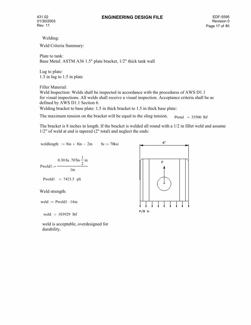
Welding:
Weld Criteria Summary: Plate to tank: Base Metal: ASTM A36 1.5" plate bracket, 1/2" thick tank wall Lug to plate: 1.5 in lug to 1.5 in plate Filler Material: Weld Inspection: Welds shall be inspected in accordance with the procedures of AWS D1.1 for visual inspections. All welds shall receive a visual inspection. Acceptance criteria shall be as defined by AWS D1.1 Section 6. Welding bracket to base plate: 1.5 in thick bracket to 1.5 in thick base plate:
The maximum tension on the bracket will be equal to the sling tension. Ptotal 35500 lbf=
The bracket is 8 inches in length. If the bracket is welded all round with a 1/2 in fillet weld and assume 1/2" of weld at end is tapered (2" total) and neglect the ends:
weldlength 8in 8in+ 2in−:= fu 70ksi:=
Pweld10.30 fu⋅ .707⋅ in
12⋅ in
1in:=
Pweld1 7423.5 pli=
Weld strength:
weld Pweld1 14⋅ in:=
weld 103929 lbf=
weld is acceptable, overdesigned for durability.

431.02 01/30/2003 Rev. 11
ENGINEERING DESIGN FILE
EDF-5595Revision 0
Page 18 of 46
Bracket:
To assume distribution of the load to the base plate and to stiffen the bracket, gusset plates will be added to each side.
Use 1" gusset plates welded with 3/8 in fillets to baseplate.
Use 3/8" fillet to weld gussets to bracket.
Pweld20.30 fu⋅ .707⋅ in
38⋅ in
1in:= Pweld2 5567.625 pli=
Welding Baseplate to tank: 1-1/2" baseplate to 1/2" tank shell:
Weld: Try using a 3/8" fillet all around the lug plate to limit overwelding the tank wall (thick = 1/2")
for 3/8" fillet weld using 304L stainless steel as a base metal; Use INEEL Weld Procedure CS 3.0, CS 3.04, CS 6.9 Electrodes: E 309 AWS D1.6 Table 3.3 Fu = 75ksi (E 309 -17 and 18 has Fu=80 ksi) but will use the lower value of 75 ksi

431.02 01/30/2003 Rev. 11
ENGINEERING DESIGN FILE
EDF-5595Revision 0
Page 19 of 46
Fillet weld strength from AWS table 2-10 minimum weld size: 5/16" fu 75ksi:=
On throat of weld:
Pweld20.30 fu⋅ .707⋅ in
38⋅ in
1in:= Pweld2 5965.312 pli=
If the plates are welded all round to assure distribution, reduce length by 1/2 in at each corner for weld taper. Also assume 12" of weld is bad or cannot be placed due to interferences :
perimeter 2ft 2ft+ 1ft+ 1ft+ 4in− 12in−:=
perimeter 56 in=
weld strength: baseweld Pweld2 perimeter⋅:= baseweld 334057.5 lbf=
dcweldPtotal
baseweld:= dcweld 0.106= ok

431.02 01/30/2003 Rev. 11
ENGINEERING DESIGN FILE
EDF-5595Revision 0
Page 20 of 46
Rigging Design:
Proposed Spreader Bar: Spreader beam is owned by INEEL Capacity: 50 tons This beam has the correct spread and can be used even when the tanks are loaded with waste. The rigging design for lifting the loaded tanks (weight approx 71,000 lb) will be performed by others. However the lift brackets must accomodate the final lifting weight. Therefore, some components such as the shackles will require a longer reach and thicker pin to fit properly in the brackets.
Rigging Requirements for lifting tanks from excavation: Tanks will have waste removed, but may have 6000 lbs of dry solidification agent deposited inside.Total weight for lift: 15,000 lbs + 6000 lbs = 21,000 lbs Lift1 21000 lbf:= P 21000 lbf:=
P2
10500 lbf=
Lift from excavation will utilize spreader beam for a controlled lift. Final rigging design will be part of subcontract, however a rigging design will be provided by this analysis to provide the design criteria
Shackles: shackles need to fit into bracket holes (2-1/32" diam) without too much play to prevent twisting or slipping of the shackle while connected to the bracket. Therefore shackles shall have a 2" pin. Specify a Crosby G-209 Screw Pin anchor Shackle, 1-3/4" nominal. This shackle has a pin diameter of 2", a through opening reach of 7" and a rated capacity of 25 tons. The spread of the pin base is 2.88" which will allow use in the 1-1/2 " plate brackets. Although much over the required load capacity, it is the fit up in the bracket which is desired.
Balanced load distribution would yield an equal vertical component of force at each lift bracket of 10,500 lbs. Allow for an over loading of each sling due to load shift of 25%. Bottom Slings:
Force 10500lbf 1.25⋅:= Force 13125 lbf= use 15,000 lb capacity slings as a minimum for bottom slings
Top Slings:

431.02 01/30/2003 Rev. 11
ENGINEERING DESIGN FILE
EDF-5595Revision 0
Page 21 of 46
Vertical component: Y 13125lbf:= assume a sling angle of 60 degrees
φ 60deg:=
Actual force: tension13125lbfsin φ( ):= tension 15155.445 lbf=
Summary: Slings: Use 18,000 lb capacity slings Top Slings: , minimum angle 60 degrees Shackles: use (6) 1-3/4" Nominal Crosby G-209 Screw Pin Anchors, Min Capacity 25 ton
BottomDC10500lbf15000lbf
:= BottomDC 0.7=
TopDC15155lbf18000lbf
:= TopDC 0.842=

431.02 01/30/2003 Rev. 11
ENGINEERING DESIGN FILE
EDF-5595Revision 0
Page 22 of 46

431.02 01/30/2003 Rev. 11
ENGINEERING DESIGN FILE
EDF-5595Revision 0
Page 23 of 46
Tank Analysis: The tank was modeled using a finite element analysis program, STAAD.Pro 2004 to determine its capability of safely holding the volume of solidified waste within while being lifted. This analysis will also determine if the tanks can be supported by saddles or cribbing during the solidification process. STAAD.Pro 2004 has been validated and verified for use in finite element plate analysis and is documented in EDF-5276. Tank Weight as determined previously: wt = 14,248 lbf based on wall thickness of 1/2-inch Per K. Wendt Email on 2/10/05, the weight of the solidified waste wil lequal 37,000 lbs for all three tanks, but requested the analysis consider only two tanks for the total volume of contents.
Therefore: 37000lbf 3⋅
255500 lbf= per tank
The material will fill approximately 2/3 of the volume of the 10,000 gallon tanks
To determine the distribution of the mass of waste in the tank, the STAAD.Pro model was used. The top 1/3 of thetank was deleted and the empty weight of the remaining tank calculated by STAAD.Pro to be 10,748 lbf. This value was then used to determine the area of the bottom 2/3. Tank weight = Area x thickness x γsteel and solving:
Area11309lbf
0.5in 490⋅ pcf:= Area 553.91ft2=
If this area is used for the distribution of the 55,500 lbs of solidified waste:
55500lbfArea
100.197psf= This value will be applied to the tank elements in the bottom 2/3 of the tank. The total weight of the tank will be checked to verify the values are correctly applied.
total weight should be a minimum of: 55500lbf 14248lbf+ 69748 lbf=
Tank model supports: to model the support conditions of the tank during lifting, the lifting bracket base plate is modeled on the tank using 1.5" thick plate. Supports are used around the perimeter (approximate) of this base plate at the approximate locations of the continuous weld around the plate connecting to the tank. This is conservative since the supports are at points, and not continuous. The supports around the perimeter of the plate are released in the x and z axis to resist only vertical loads. Restraint in the x and z axis is provided at four exterior nodes on the tank. The tanks are stainless steel, assumed to be 304L Fy =30 ksi Fu = 80 ksi The resulting stresses in the tank vessel shall be acceptable up to 75% of yield values. Stresses up to yield could be accepted since this is a one time lift only to dispose of the tanks.

431.02 01/30/2003 Rev. 11
ENGINEERING DESIGN FILE
EDF-5595Revision 0
Page 24 of 46
STAAD.Pro Model
The statics check below indicates that the total weight calculated equals 70, 740 lbs, which is slightly greater than the required 69,748 lbs. OK

431.02 01/30/2003 Rev. 11
ENGINEERING DESIGN FILE
EDF-5595Revision 0
Page 25 of 46
Pressure loads are applied in the global Y axis. This loading was chosen after several variations and resulted in the largest resulting stresses.

431.02 01/30/2003 Rev. 11
ENGINEERING DESIGN FILE
EDF-5595Revision 0
Page 26 of 46
STAAD.Pro 2004 Analysis Summary: The plate stress summary below shows a maximum plate stress of 17,400 psi located at the ends of the tank, adjacent to the lift bracket plate corners. As shown in the stress contour diagrams, the maximum stress is a point stress which dissapates quickly. This maximum stress is only 58% of the yield stress of 30,000 psi, and is acceptable.
Isometric View of Stress Contours

431.02 01/30/2003 Rev. 11
ENGINEERING DESIGN FILE
EDF-5595Revision 0
Page 27 of 46
Isometric View of Von Mises Stresses

431.02 01/30/2003 Rev. 11
ENGINEERING DESIGN FILE
EDF-5595Revision 0
Page 28 of 46
Checking the model using an impact factor of 1.5 on the loaded weight results in a maximum plate stress of 26.1 ksi at the corners of the lift bracket plate.
These results show that even with an impact force due to jerking or dropping of the tank, the stress is still only 87% of yield.

431.02 01/30/2003 Rev. 11
ENGINEERING DESIGN FILE
EDF-5595Revision 0
Page 29 of 46
Tank Support on Cribbing: Design cribbing to support tanks V-1, 2, 3 on the transport trailer, or in a staging area. Cribbing shall be designed to be used on a surface with a bearing capacity of 3000 psf.. Tanks shall be assumed to be fully loaded with the solidified material (55,500 lb payload). Seismic and wind will be ignored, since the tanks will be tied down while on the trailer.
Weights: Tankweight 15000 lbf:= (rounded up)
solidwaste 55500lbf:=
stageweight Tankweight solidwaste+:= stageweight 70500 lbf=
for miscellaneous tarps, etc, round up to 71,000 lbf
weight 71000 lbf:=

431.02 01/30/2003 Rev. 11
ENGINEERING DESIGN FILE
EDF-5595Revision 0
Page 30 of 46
If 8x12 nominal DF-L (N) timbers are used and the length of each saddle is limited to 8' due to the maximum trailer width. The actual dimensions for 8x12 timber is: 7.5" x 11.5"
The bearing area for a single saddle, 8' long and neglecting outriggers is: 11.5in 8⋅ ft 7.667 ft2=
Number of saddles required for 3000 psf bearing area: 7.667ft2 3000⋅ psf 23001 lbf=
71000lbf23001lbf
3.087= or three saddles required if evenly distributed.
center timber would however see 5/8 of the load: 71000 lbf58⋅ 44375 lbf=
44375lbf
7.667ft25787.792psf= which would exceed the 3000 psf bearing capacity
therefore, use four supports for overall stability and load variations.
if a 14ft dimension is assumed as an overall length and even spacing then:
w71000lbf
14ft:= 14ft
34.667 ft=
end support load: R14 w⋅ 4.667⋅ ft
10:= R1 9467.343 lbf=
interior supports: R2
11 w⋅ 4.667⋅ ft10
:= R2 26035.193 lbf=
R2
7.667ft23395.747psf= although over the 3000 psf, the outrigger skid beams were neglected and would
reduce the bearing load. ok
Timber capacities: Douglas fir Larch North has a bearing compression design values of 625 psi for compression perpendicular to the grain.
arc length supporting tanks approximately 8.166 ft from autocad model:
fc 625psi:= allowable load per foot 625psi 7.5⋅ in 12⋅ in 56250lbf=
Bearing Surface Area: 7.5in 8.166⋅ ft 5.104 ft2=
for 2 saddles: 71000lbf2
35500lbf= Fc35500lbf
5.104ft2:= Fc 48.301 psi=
Ok timbers will not crush. Use 4 saddles per tank.

431.02 01/30/2003 Rev. 11
ENGINEERING DESIGN FILE
EDF-5595Revision 0
Page 31 of 46
Cribbing Saddle connections:
If five (5) 3/4 inch A36 threaded rods are used to tie the 8x12 timbers together, the total shearing strength of the assembly would be:
AISC Table 1-D for A307 rod, 3/4-inch Fv 4400 lbf:= 5 Fv⋅ 22000 lbf= per saddle
The lateral force requirement for cargo securement systems of 49 CFR 393.102 is 0.5g and for forward or rearward is 0.8 g's. The tanks will be secured with tiedowns, but check shear capability of saddles only
Forward: R2 .8⋅2
10414.077 lbf=
lateral: R2 .5⋅2
6508.798 lbf= per saddle < 22,000 lbf ok
bolts are capable of resisting shear.

431.02 01/30/2003 Rev. 11
ENGINEERING DESIGN FILE
EDF-5595Revision 0
Page 32 of 46
Shear Between timbers due to radial loading
for 4 saddles: the interior saddles reactions: R2 26035.193 lbf=
the radial dimension of the bearing area determined from autocad model:
Lr 8.166 ft:=R2Lr
3188.243plf=
horizontal shear component, worst angle at approx 50 degrees near top of saddle. This angle drops significantly towards the bottom of the tank.
v cos 39deg( ) 3188⋅ plf:= v 2477.541 plf= vertical component: y sin 39deg( ) 3188⋅ plf:=
y 2006.273 plf=
friction coef for wood: .35 (Modern College Physics, 6th ed H.E. White pg 118)
friction force: between timbers 0.35 y⋅ 702.196 plf=
At top timber:
total lateral force: v 11.375⋅ in 2348.503lbf=
friction resistance: 855plf 1⋅ ft 855 lbf=
rod shear strength: 4.4 kips
ok

431.02 01/30/2003 Rev. 11
ENGINEERING DESIGN FILE
EDF-5595Revision 0
Page 33 of 46
second section:
lateral force: v 2.25⋅ ft 5574.468 lbf=
friction: 855plf 2.25⋅ ft 1923.75lbf=
net 4611lbf 1924lbf−:= net 2687 lbf=
rod shear strength 4.4 kips ok
conservative since horizontal angle is reduced to approximately 30 deg, but worst case load is assumed.
Lateral Bracing
Lateral Force: if the 0.8g force due to truck accelleration/stopping is assumed then the lateral force would be: Plat 71000lbf 0.8⋅:= Plat 56800 lbf=

431.02 01/30/2003 Rev. 11
ENGINEERING DESIGN FILE
EDF-5595Revision 0
Page 34 of 46
If only the braces in compression are use, then two braces would resist this load
Fbrace Plat cos 32deg( )⋅:=
Fbrace 48169.132 lbf=
for two braces: Fbrace2
24084.566lbf=
Check Brace Using StruCalc 6.0 and 24.1 kips

431.02 01/30/2003 Rev. 11
ENGINEERING DESIGN FILE
EDF-5595Revision 0
Page 35 of 46
Use a 6x6 DFL timber for brace: Allowable stress = 913 psi, actual = 797 psi ok.
for 3/4 inch A307 rod, and since this is an impact force, use ultimate strength:
Ult 58ksi:= Arearod π .375in( )2 ⋅:= Arearod 0.442in2=
Vult 0.442in2 58⋅ ksi:= Vult 25636 lbf=
shear at base will be resisted by two 3/4-in rods, one through the brace and one through the saddle.
shear per rod: 24084lbf2
12042 lbf=
stress per rod: 12042lbfArearod
27.258 ksi=
less than yield stress, ok
Bearing on timbers: Ref ANSI/NFPA NDS National Design Standard, Section 8.2 single shear conections and considering the 8x12 skid. The diagonal brace will transfer the shear to the saddle and skid by contact bearing even if the brace bolt fails.
Table 8A Dowel Bearing Strength: for bearing strnegth paralle to grain for DFL-n, fe=5500 psi
Equation 8.2.1 for yield mode Im (bearing dominate yield of wood fibers)
ZD tm⋅ Fem⋅
4 K⋅:=
Fem D .75in:= (bolt diam) tm 7.5 in:= (thickness of 8x12)
Fem 5500 psi:= (dowel bearing strength)
K 1:= (no angle through skid)
ZD tm⋅ Fem⋅
4 K⋅:= Z 7734.375 lbf= (allowable shear values)
If an additional 2 bolts are added, then 4 bolts will resist the shear:
24084lbf4
6021lbf= ok < Z = 7734 lbf
add 2 bolts and block to the opposite side of saddle to resist shear.

431.02 01/30/2003 Rev. 11
ENGINEERING DESIGN FILE
EDF-5595Revision 0
Page 36 of 46
Brace Connection:
Cribbing Lifting Plan: Design cribbing to be lifted as an assembly: Top horizintal braces (4x6) will be used and rigging can be choked around for ease. Since the top brace is continuous through each saddle and tied with the rods, asembly should act togther.
Cribbing assembly weight
cribbing weight: 8x12 df-L timbers from NDS Supplement, weight approx 21 plf
8ft 4⋅ 6ft+( ) 21⋅ plf 798 lbf= per saddle
for 4 saddles: 800 lbf 4⋅ 3200 lbf= Skids: 16ft 21⋅ plf 2⋅ 672lbf=
cribwt 672lbf 3200lbf+:= cribwt 3872 lbf=
round to 4000 lbf crib 4000 lbf:=
each side beam will carry 1/2 the load or 2000 lbf
w 2000lbf14ft
:=
w 142.857 plf=

431.02 01/30/2003 Rev. 11
ENGINEERING DESIGN FILE
EDF-5595Revision 0
Page 37 of 46
Analyzing the 4x6's using StruCalc 6.0
Therefore 4x6 beams are ok for lifting.

431.02 01/30/2003 Rev. 11
ENGINEERING DESIGN FILE
EDF-5595Revision 0
Page 38 of 46
Rigging: Use 4 endless slings and choke around 4x6s at the tow center saddles.
select each choker to support 1/2 the total load. (2000 lbf)
for a min sling angle of 60 deg:
ten2000lbf
sin 60deg( ):=
ten 2309.401lbf=
therefore use 2500 lb slings
for a sling angle of 80deg:
ten2000 lbf
sin 80deg( ):=
ten 2030.853 lbf=
use 2500 lb slings and angle is not critical.

431.02 01/30/2003 Rev. 11
ENGINEERING DESIGN FILE
EDF-5595Revision 0
Page 39 of 46
Crane Verification:
Since the weight of the empty V-tanks has increased due to the fact that the original design assumed 1/4-in steel was used and it has been verified in the field that the actual thickness is 1/2-inch, the crane used to make the initial lifts from the excavation must be re-investigated. Tank calculated weight with 1/2" thickness: weight1 15000lbf:=
Check the capacity of the INEEL Grove 9120 Mobile Crane:
using the weight of the tank at 15,000 lbf and 6000 lbf of dry solidification agent the total payload is 21,000 lbf
Crane Load Data:
grossweight 15000lbf 7240lbf+ 6000lbf+:= grossweight 28240 lbf=
ROUND TOTAL WEIGHT TO 28,400 LBS.
Total lifted load: 28,400 lbs > capacity of 24,450 lbs
The table above indicates that the Grove 9120 cannot be used to make the picks. if the solidification agent is not added in the excavation only V-3 could be lifted empty with the 9120. Therefore a larger crane will be used.

431.02 01/30/2003 Rev. 11
ENGINEERING DESIGN FILE
EDF-5595Revision 0
Page 40 of 46
The crane to be used for lifting will be assumed to be the Grove GMK 6220, owned by Mullen Crane and Transport. This crane is a mobile, all-terrain crane used recently for the TAN-725 Stack Demolition. Crane Load Data Provided by Mullen Crane: Note Spreader beam weight is for Mullen Provided beam and is a maximum weight.
totalload 15000lbf 7700lbf+ 6000lbf+:=
totalload 28700 lbf=
The load chart below indicates that at the 60-ft, 70-ft and 80-ft radii, the GMK 6220 crane has suffcient capacity.
From Load Charts for GMK 6220 Crane
Grove GMK 6220 Capacity Chart
The Grove GMK 6220 crane can safely lift the V-tanks from the current crane pad and with up to 6,000 lbs of added weight from solidification agent.

431.02 01/30/2003 Rev. 11
ENGINEERING DESIGN FILE
EDF-5595Revision 0
Page 41 of 46
GMK 6220 Crane Site Plan

431.02 01/30/2003 Rev. 11
ENGINEERING DESIGN FILE
EDF-5595Revision 0
Page 42 of 46
Check Stability of Transport Trailer:
Vertical Forces:
Tankdead 15000lbf:= Tank contents: contents 55000 lbf:= (assume heaviest load)
cribbing weight: 8x12 df-L timbers from NDS Supplement, weight approx 21 plf
8ft 4⋅ 6ft+( ) 21⋅ plf 798lbf= per saddle
for 4 saddles: 800lbf 4⋅ 3200 lbf= Skids: 16ft 21⋅ plf 2⋅ 672 lbf=
cribwt 672lbf 3200lbf+:= cribwt 3872 lbf=
Trailerwt 15200lbf:= (from D. Petersen, P&T)

431.02 01/30/2003 Rev. 11
ENGINEERING DESIGN FILE
EDF-5595Revision 0
Page 43 of 46
Vertical Load total: Vert Tankdead contents+ cribwt+ Trailerwt+:=
Vert 89072lbf=
resisting moment: Rm Vert 4⋅ ft:= Rm 356.288 kip ft⋅=
determine the maximum accelleration that the trailer can withstand without tipping.
Tankdead contents+ 70000lbf=
P 70000lbf:= P 70000 lbf=
If this lateral force is applied at the centroid of the volume:
moment arm would be equal to 10-ft
Over turning Moment: Om P 10⋅ ft:= Om 700kip ft⋅=
FSRmOm
:=
the maximum lateral accelleration for a factor of safety of 1.5 to 1 is:
OmmaxRm1.5
:= Ommax 237.525kip ft⋅=
Ommax = 70,000 lbf x g x 10ft
gmaxOmmax
70kip 10⋅ ft:= gmax 0.339=
Speed will be reduced during transport. Friction mats will be used under cribbing capable of providing frictional forces equal to 0.8 g min.
431.02 01/30/2003 Rev. 11
ENGINEERING DESIGN FILE
EDF-5595Revision 0
Page 44 of 46
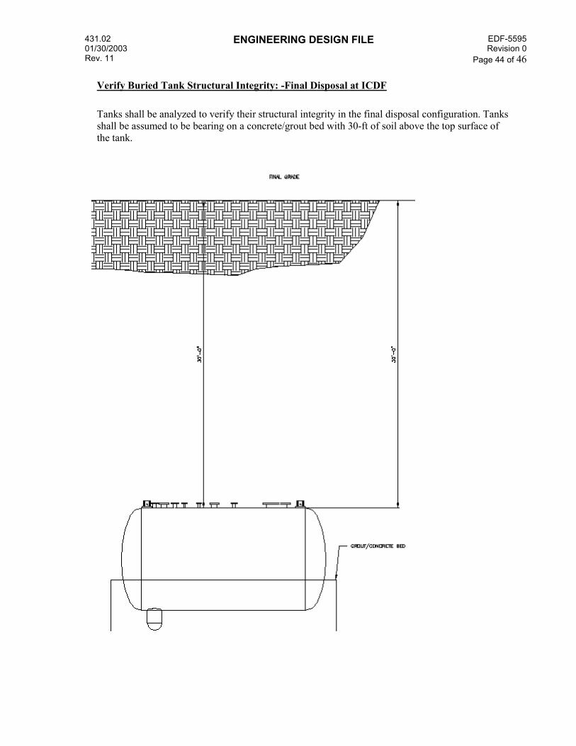
Verify Buried Tank Structural Integrity: -Final Disposal at ICDF
Tanks shall be analyzed to verify their structural integrity in the final disposal configuration. Tanks shall be assumed to be bearing on a concrete/grout bed with 30-ft of soil above the top surface of the tank.

431.02 01/30/2003 Rev. 11
ENGINEERING DESIGN FILE
EDF-5595Revision 0
Page 45 of 46
Soil Loading on Tanks:
Assuming "at-rest" soil pressure:
Using the model created in STAAD.Pro 2004, the soil loads on the tank will be applied using STAAD's hydrostatic pressure function. This function allows varying pressure loads to be applied to plates based on a maximum and minimum pressure. The program automatically calculates the pressure for a specific plate based on its location along the vertical axis.
Assumed Soil Properties: φ 30deg:= γ 115pcf:=
Ko 1 sin φ( )−:= Ko 0.5=
depth to top of tank = 30-ft depth to bottom of tank = 40-ft, (neglecting grout bed)
σbottom Ko γ⋅ 40⋅ ft:= σbottom 2300psf=
σtop Ko γ⋅ 30⋅ ft:= σtop 1725psf=
for convenience, the soil loads were averaged for a uniform load application. The soil loads were applied to the STAAD.Pro model using several different applications and the controlling stress used. The soil pressure was applied radially in each plate's local z-axis, and the pressure was applied in the global axis (both z and x) which produced the greatest stresses.
431.02 01/30/2003 Rev. 11
ENGINEERING DESIGN FILE
EDF-5595Revision 0
Page 46 of 46
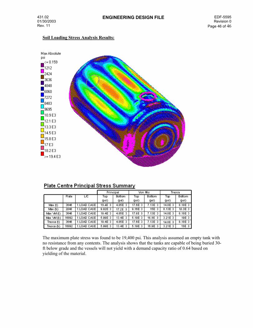
Soil Loading Stress Analysis Results:
The maximum plate stress was found to be 19,400 psi. This analysis assumed an empty tank with no resistance from any contents. The analysis shows that the tanks are capable of being buried 30-ft below grade and the vessels will not yield with a demand capacity ratio of 0.64 based on yielding of the material.