tsb polarity for data centers rev.1_2013
TRANSCRIPT
Polarity for Use in Data Centers, Sans and Clouds TSB Rev.1-2013 NetIG Technical Systems Bulletin (TSB) For Help & Assistance Call NetIG @ (425) 291-4200 or (866) 814-8615
NetIG – Technical Systems Bulletin (TSB) – Polarity for Use in Data Centers SANs and Clouds
Liability Disclaimer Regarding Polarity Used in Pre-Terminated Optical Fiber Trunks, Harnesses and Assemblies. As the industry advances from duplex 1/10GbE to a heightened migration to IEEE 802.3ba 40/100GbE, ANSI/TIA-568 and ANSI/TIA-942 Standards based solutions and beyond, the greater the emphasis that is being placed on utilizing MPO multi-fiber, multi-channel parallel optical fiber trunk and harness (fan-out) solutions, and in coordination with the continued use of LC connectors. NetIG’s Rapid Cabling Infrastructure (RCI) pre-terminated MPO high-density solutions along with plug and play adapter plates, cassettes and couplers (adapters), provides the means for a successful migration to a higher performing plane of bandwidth all designed and engineered to work in interoperable union. >>>In order to avoid any confusion and error regarding the User’s Polarity Methodology, it is the recommendation of NetIG that the User carefully evaluate, scrutinize, and physically map-out their accepted and now specified polarity to be used within their Network Architecture, including jumpers, adapter plates, cassettes, couplers (adapters), harnesses and trunks, literally everything that emulates from the initial TX transmit port to the final RX receive port must be considered and understood.<<< Polarity sample method types are depicted as defined in ANSI/TIA-568-C.0-2-2012, “Generic Telecommunications Cabling for Customer Premises – Addendum 2, General Updates”, and ANSI/TIA-568-C.3-1-2011, “Optical Fiber Cabling Components Standard – Addendum 1, Addition of OM4 Cabled Optical Fiber and Array Connectors”, to help the User determine what polarity method they will specify. >>>It is the User’s responsibility to understand and specify the polarity methodology that the User desires NetIG to utilize, as the User has the responsibility for managing their data centers.<<< All array connectivity methods share the same purpose and priority, to create an optical fiber pathway from the transmit TX port of one device to the receive RX port of another device. For the sake of network interoperability, it is recommended that the connectivity-polarity method be selected in advance and that the same methodology be consistently maintained throughout the entirety of the installation. To date, there are a minimal number of published Standards that adequately stipulate polarity solutions. Optical fiber cable and connectivity manufacturers vary greatly in what they are recommending to Customers regarding polarity. The images in this document are ANSI/TIA Standards based and have been enhanced for better understanding. As the industry continues to move forward in utilizing 40/100GbE solutions, all components must be manufactured to the layout of the designated connectivity method. Differences cannot be reconciled by flipping or switching connector positions in the field anymore.

Polarity for Use in Data Centers, Sans and Clouds TSB Rev.1-2013 NetIG Technical Systems Bulletin (TSB) For Help & Assistance Call NetIG @ (425) 291-4200 or (866) 814-8615
1.1 Type A: 1-1 Fibers positioned sequentially, i.e. 1 – 1 & 12 – 12
Key Up Female w/o pins Key Down Female w/o pins Position 1 Blue Fiber #1 Position 1
Position 12 Aqua Fiber #12 Position 12 End Fiber Sequence (viewing the end face of the connector with key up)_____
Near 1 2 3 4 5 6 7 8 9 10 11 12
Far 1 2 3 4 5 6 7 8 9 10 11 12
2

Polarity for Use in Data Centers, Sans and Clouds TSB Rev.1-2013 NetIG Technical Systems Bulletin (TSB) For Help & Assistance Call NetIG @ (425) 291-4200 or (866) 814-8615
Key Up Female w/o pins Key Up Female w/o pins
Position 1 Blue Fiber #1 Position 12
Position 12 Aqua Fiber #12 Position 1
3
1.2 Type B: 1-1 Fibers positioned in reverse sequence, i.e. 1 – 12 & 12 – 1
End Fiber Sequence (viewing the end face of the connector with key up)_____
Near 1 2 3 4 5 6 7 8 9 10 11 12
Far 12 11 10 9 8 7 6 5 4 3 2 1

Polarity for Use in Data Centers, Sans and Clouds TSB Rev.1-2013 NetIG Technical Systems Bulletin (TSB) For Help & Assistance Call NetIG @ (425) 291-4200 or (866) 814-8615
Key Up Female w/o pins Key Down Female w/o pins
4
1.3 Type C: 1-1 Fibers positioned in flipped pairs, i.e. 1 – 2; 2 – 1; 11 – 12 & 12 – 11
End Fiber Sequence (viewing the end face of the connector with key up)______ Near 1 2 3 4 5 6 7 8 9 10 11 12
Far 2 1 4 3 6 5 8 7 10 9 12 11
Orange Fiber #1
Rose Fiber #12
Blue Fiber #1
Aqua Fiber #12
Cross Pair
Position 1
Position 12 Position 12
Position 1

Polarity for Use in Data Centers, Sans and Clouds TSB Rev.1-2013 NetIG Technical Systems Bulletin (TSB) For Help & Assistance Call NetIG @ (425) 291-4200 or (866) 814-8615
5
Cross Pair

Polarity for Use in Data Centers, Sans and Clouds TSB Rev.1-2013 NetIG Technical Systems Bulletin (TSB) For Help & Assistance Call NetIG @ (425) 291-4200 or (866) 814-8615
12 – fiber configurations and migration
1/10G channel 12-fiber legacy configuration:
LC patch cord 12 fiber MPO-LC 1X12 fiber MPO 12 fiber MPO-LC LC patch cord module trunk cable module
MPO is the designated interface for multimode 40/100G and it is backward-compatible with legacy 1G/10G applications as well. Its small, high-density form factor is ideal with higher-speed Ethernet equipment.
40G channel 12-fiber legacy configuration:
8 fiber MPO patch cord 2X12 fiber to 3X8 fiber 2X12 fiber MPO 2X12 fiber to 3X8 fiber 8 fiber MPO patch cord MPO module trunk cable MPO module
2X12 fiber to 3X8 fiber MPO adapter 2X12 fiber MPO MPO adapter 2X12 fiber to 3X8 fiber MPO harness plate trunk cable plate MPO harness
100G channel 12-fiber legacy configuration:
2X12 fiber to 1X24 fiber MPO adapter 2X12 fiber MPO MPO adapter 2X12 fiber to 1X24 fiber MPO harness plate trunk cable plate MPO harness
Parallel optics: Laser-optimized multimode 40G and 100G Ethernet employ parallel optics. Data is transmitted and received simultaneously on MPO interfaces through 10G simplex transmission over each individual strand of the array cable. Current IEEE channel - lane assignments for active equipment interfaces determine the transmission methodology.

Polarity for Use in Data Centers, Sans and Clouds TSB Rev.1-2013 NetIG Technical Systems Bulletin (TSB) For Help & Assistance Call NetIG @ (425) 291-4200 or (866) 814-8615
7
2.1 Multiple duplex connectivity Methods for 10GbE
2.1.1 Method A 10GbE
Polarity for Use in Data Centers, Sans and Clouds TSB Rev.1-2013 NetIG Technical Systems Bulletin (TSB) For Help & Assistance Call NetIG @ (425) 291-4200 or (866) 814-8615
8
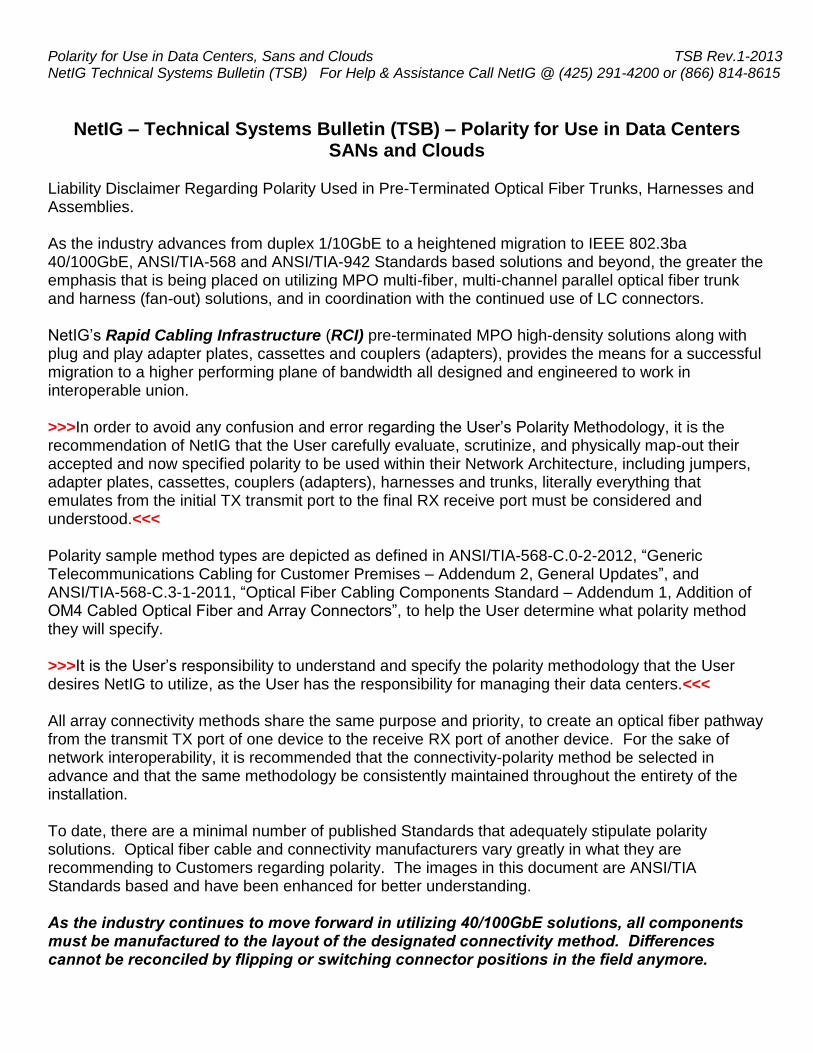
2.1.2 Method B 10GbE
Polarity for Use in Data Centers, Sans and Clouds TSB Rev.1-2013 NetIG Technical Systems Bulletin (TSB) For Help & Assistance Call NetIG @ (425) 291-4200 or (866) 814-8615
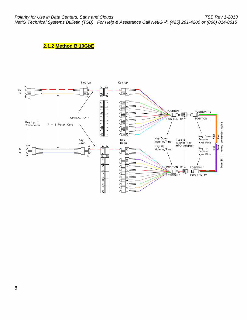
Please Note for Reference: Parallel Optics Lane
40G 12-Fiber MPO
100G 2 X 12-Fiber MPO
100G 24-Fiber MPO
2.1.3 Method C 10GbE
Cross Pair

Polarity for Use in Data Centers, Sans and Clouds TSB Rev.1-2013 NetIG Technical Systems Bulletin (TSB) For Help & Assistance Call NetIG @ (425) 291-4200 or (866) 814-8615
10
2.2 Parallel signal Connectivity Methods for 40GbE (1 plug 1 row Transceiver)
2.2.1 Method A 40GbE

Polarity for Use in Data Centers, Sans and Clouds TSB Rev.1-2013 NetIG Technical Systems Bulletin (TSB) For Help & Assistance Call NetIG @ (425) 291-4200 or (866) 814-8615
2.2.2 Method B 40GbE
11

Polarity for Use in Data Centers, Sans and Clouds TSB Rev.1-2013 NetIG Technical Systems Bulletin (TSB) For Help & Assistance Call NetIG @ (425) 291-4200 or (866) 814-8615
2.2.3 Method C 40GbE
`
12
Cross PairCross Pair

Polarity for Use in Data Centers, Sans and Clouds TSB Rev.1-2013 NetIG Technical Systems Bulletin (TSB) For Help & Assistance Call NetIG @ (425) 291-4200 or (866) 814-8615
2.3 Parallel signal Connectivity Methods for 100GbE (Scenario 1: 2 plugs 1 row Transceiver)
2.3.1 Method A 100GbE scenario 1
13

Polarity for Use in Data Centers, Sans and Clouds TSB Rev.1-2013 NetIG Technical Systems Bulletin (TSB) For Help & Assistance Call NetIG @ (425) 291-4200 or (866) 814-8615
14
2.3.2 Method B 100GbE scenario 1
Polarity for Use in Data Centers, Sans and Clouds TSB Rev.1-2013 NetIG Technical Systems Bulletin (TSB) For Help & Assistance Call NetIG @ (425) 291-4200 or (866) 814-8615
15
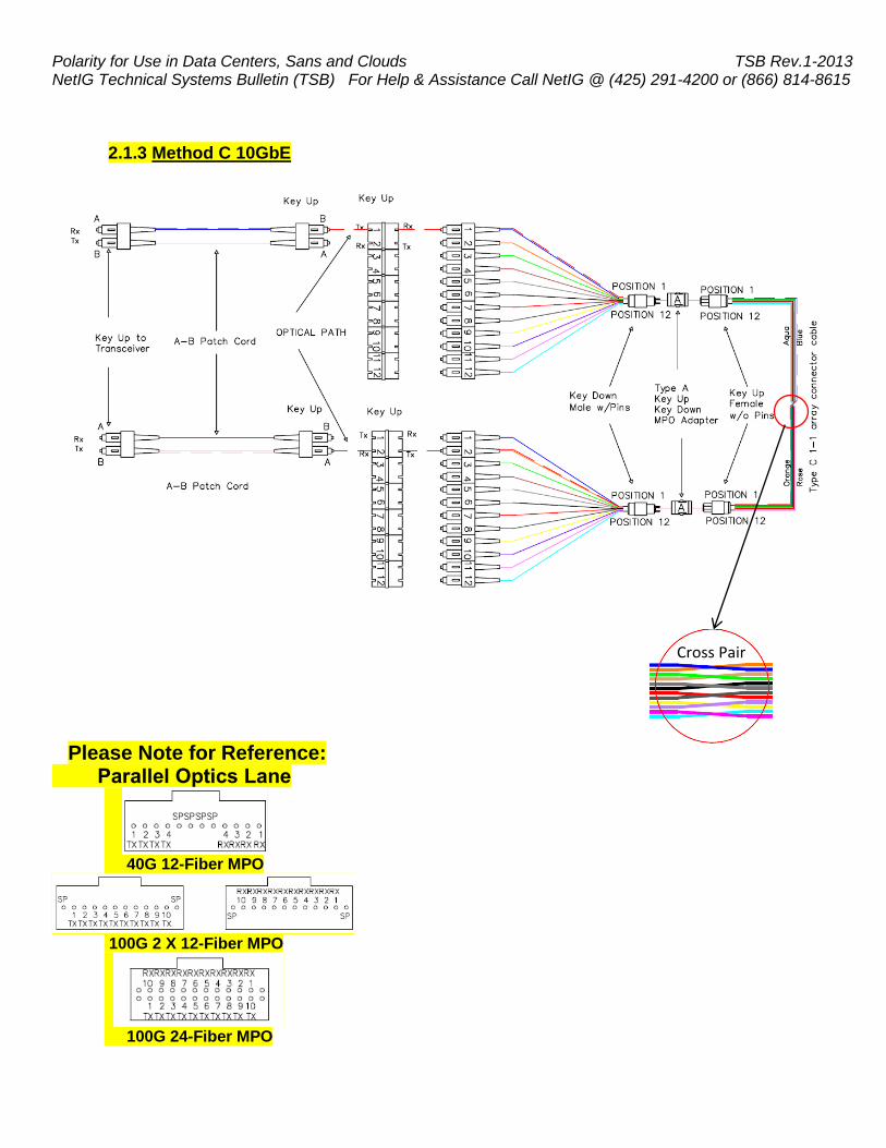
2.3.3 Method C 100GbE scenario 1
Cross Pair
Cross Pair

Polarity for Use in Data Centers, Sans and Clouds TSB Rev.1-2013 NetIG Technical Systems Bulletin (TSB) For Help & Assistance Call NetIG @ (425) 291-4200 or (866) 814-8615
24 – fiber configurations and migration
1/10G channel 24-fiber legacy configuration:
LC patch cord 24 fiber MPO-LC 1X24 fiber MPO 24 fiber MPO-LC LC patch cord module trunk cable module
40G channel 24-fiber legacy configuration:
8 fiber MPO patch cord 1X24 fiber to 3X8 fiber 1X24 fiber MPO 1X24 fiber to 3X8 fiber 8 fiber MPO patch cord MPO module trunk cable MPO module
1X24 fiber to 3X8 fiber MPO adapter 1X24 fiber MPO MPO adapter 1X24 fiber to 3X8 fiber MPO harness plate trunk cable plate MPO harness
100G channel 24-fiber legacy configuration:
1X24 fiber MPO patch cord MPO adapter 1X24 fiber MPO MPO adapter 1X24 fiber MPO patch cord Plate trunk cable plate
As these illustrations point out, migrating to a 12-fiber-connector-based infrastructure from 1 or 10G, to 40 or 100G, will require additional components in every scenario than migrating to a 24-fiber connector based infrastructure. 16

Polarity for Use in Data Centers, Sans and Clouds TSB Rev.1-2013 NetIG Technical Systems Bulletin (TSB) For Help & Assistance Call NetIG @ (425) 291-4200 or (866) 814-8615
17
2.4 Parallel signal Connectivity for Methods 100GbE (Scenario 2: 1 plug 2 rows Transceiver)
2.4.1 Method A 100GbE scenario 2

Polarity for Use in Data Centers, Sans and Clouds TSB Rev.1-2013 NetIG Technical Systems Bulletin (TSB) For Help & Assistance Call NetIG @ (425) 291-4200 or (866) 814-8615
18
2.4.2 Method B 100GbE scenario 2

Polarity for Use in Data Centers, Sans and Clouds TSB Rev.1-2013 NetIG Technical Systems Bulletin (TSB) For Help & Assistance Call NetIG @ (425) 291-4200 or (866) 814-8615
19
2.4.3 Method C 100GbE scenario 2
Cross Pair
Cross Pair

Polarity for Use in Data Centers, Sans and Clouds TSB Rev.1-2013 NetIG Technical Systems Bulletin (TSB) For Help & Assistance Call NetIG @ (425) 291-4200 or (866) 814-8615
Migration. With the 40G 12-fiber legacy configurations, a second trunk and another set of array harnesses will be needed to achieve 100-percent fiber utilization. For 100G, these additional components will be required for any 12-fiber legacy upgrade. On the other hand, with 24-fiber trunks, a single cable can support a 1G-100G channel and will simplify network upgrades immensely. 1G and 10G networks will link the trunks to active equipment with MPO-LC modules and LC duplex patch cords. When equipment is upgraded, modules and patch cords are exchanged for the appropriate new MPO components, with no need to install new trunks. In addition, limiting changes reduces the inherent risks to network security and integrity whenever move/add/change work is completed. Density. Higher-density connectivity in the enclosure leaves more rack space for active equipment, reducing the total amount of floor space required. Twenty-four-fiber cabling has the obvious advantage. If the active equipment is configured for 24-fiber channel/lane assignments, enclosures can have twice as many connections with the same number of ports compared to 12-fiber (or the same number of connections using only half the ports). Congestion. The flipside of density is congestion. The more connectivity you are able to run in a given footprint, the more crowded it can become at the rack or cabinet. Here again, 24-fiber MPO trunks offer a huge benefit. Anywhere there is fiber, you will have just half the number of cables versus 12-fiber. Runs carry a lighter load, fibers are easier to manage, and improved airflow reduces cooling costs. Being prepared for 40/100G is essential as within a few short years high-speed Ethernet will be common in data centers across all types of organizations. Install a high-performance 24-fiber 40/100G MPO system and realize these benefits when it is time to upgrade your network. Fewer connectivity components to be replaced or added simplifies migration and reduces costs. Higher-density connectivity leaves more rack space for active equipment. Fewer trunks reduce cable congestion throughout the data center. A 24-fiber high-speed Ethernet MPO system will prepare your network for now and the future, and lower your cost of ownership and maximize your return on investment (ROI). Polarity Methods Summarized.
ANSI/TIA-568-C Standards based polarity methods and types.
ANSI/TIA-568-C.0-2 ANSI/TIA-568-C.3-1 ANSI/TIA-568-C.0-2
Connectivity
Array Connector Assembly not pinned for 10GbE - Pinned for 40/100GbE
MPO Connector Adapter
10GbE Duplex Patch Cord
40/100GbE Array Connector Patch Cord
Not Pinned
Polarity Method A Type A Type A 1 X AA / BB 1 X Type A
1 X AB / BA 1 X Type B
Polarity Method B Type B Type B 2 X AB / BA 2 X Type B
Polarity Method C Type C Type C 2 X AB / BA 1 X Type B
1 X Type C Determine connectivity polarity method under ANSI/TIA-568-C.0-2 then to ANSI/TIA-568-C.3-1 to choose component type. For network interoperability, the polarity method type should be selected in advance and maintained throughout the entire installation including jumpers, adapter plates, cassettes, couplers, harnesses and trunks. See also NetIG Technical Systems Bulletin (TSB) on Polarity for Use in Data Centers, SAN and Cloud. 20