ts870 rev 0 - steadypower.com
TRANSCRIPT

9087A – 198th Street, Langley, BC Canada V1M 3B1 Telephone (604) 888-0110 Telefax (604) 888-3381 E-Mail: [email protected] www.thomsonPS.com
TS 910/TS 920
AUTOMATIC TRANSFER SWITCHES
OWNERS MANUAL
INSTALLATION, OPERATING & SERVICE
PM147 Rev 3 17/02/15


TS 910/TS 920 TRANSFER SWITCH
PM147 REV 3 17/02/15 1 Thomson Power Systems
TABLE OF CONTENTS
1 PRODUCT REVISION HISTORY 1
2 EQUIPMENT STORAGE 1
3 NOTES TO INSTALLER 2
3.1 APPLICATION 2
3.2 CHECK EQUIPMENT DELIVERY 2
3.3 CHECK LINE VOLTAGE/AMPERAGE 3
3.4 INSTALLATION REQUIREMENTS 3
3.5 DIELECTRIC TESTING 8
3.6 SERVICE DISCONNECT ATS CONFIGURATION 9
4 GENERAL DESCRIPTION 10
4.1 PRODUCT MODEL CODE 11
4.2 TS 910/920 OPTIONAL ACCESSORIES 12
4.3 TYPICAL COMMISSIONING PROCEDURES 12
5 GENERAL THEORY OF OPERATION 13
5.1 AUTOMATIC SEQUENCE OF OPERATION 13
5.2 SERVICE ENTRANCE AUTOMATIC TRANSFER SWITCH OPERATION 13
6 OVER CURRENT PROTECTION 16
6.1 STANDARD TS 910/920 AUTOMATIC TRANSFER SWITCH 16
6.2 SERVICE ENTRANCE RATED TS 910/920 AUTOMATIC TRANSFER SWITCH 16
7 GENERAL NOTES ON SERVICING TRANSFER SWITCH MECHANISM 17
8 TRANSFER SWITCH MECHANISM OPERATION 18
8.1 AUTOMATIC OPERATION 18
8.2 MANUAL OPERATION 18
9 RECOMMENDED MAINTENANCE 20
10 FRONT INTERIOR VIEW (100A STANDARD ATS) 21

TS 910/TS 920 TRANSFER SWITCH
PM147 REV 3 17/02/15 2 Thomson Power Systems
11 FRONT INTERIOR VIEW (100A SERVICE ENTRANCE ATS) 22
12 FRONT INTERIOR VIEW (200A STANDARD ATS) 23
13 FRONT INTERIOR VIEW (200A SERVICE ENTRANCE ATS) 24
14 FRONT INTERIOR VIEW (400A STANDARD ATS) 25
15 FRONT INTERIOR VIEW (400A SERVICE ENTRANCE ATS) 26
16 ENCLOSURE DIMENSIONS 27
17 POWER CONDUCTOR INSTALLATION 28
18 REQUIREMENTS FOR UPSTREAM CIRCUIT PROTECTIVE DEVICES 29
18.1 100A, 2P NON-SERVICE ENTRANCE ATS UPSTREAM CIRCUIT PROTECTIVE DEVICES 30
18.2 100A, 3P NON-SERVICE ENTRANCE ATS UPSTREAM CIRCUIT PROTECTIVE DEVICES 31
18.3 200A, 2P NON-SERVICE ENTRANCE ATS UPSTREAM CIRCUIT PROTECTIVE DEVICES 31
18.4 200A, 3P NON-SERVICE ENTRANCE ATS UPSTREAM CIRCUIT PROTECTIVE DEVICES 32
18.5 400A, 2P NON-SERVICE ENTRANCE ATS UPSTREAM CIRCUIT PROTECTIVE DEVICES 32
18.6 400A, 3P NON-SERVICE ENTRANCE ATS UPSTREAM CIRCUIT PROTECTIVE DEVICES 34
19 TSC 9 TRANSFER SWITCH CONTROLLER 35
19.1 DESCRIPTION 35
19.2 ELECTROSTATIC DISCHARGE PRECAUTIONS 36
19.3 DIELECTRIC TESTING 36
19.4 TSC 9 FACEPLATE 37
19.5 TSC 9 FACEPLATE LIGHTS AND PUSHBUTTON OPERATION 38
19.6 TSC 9 PRINTED CIRCUIT BOARD 39
19.7 TSC 9 OPERATING INSTRUCTIONS 43
19.8 TSC 9 OPERATING MODE DESCRIPTIONS 44
19.9 TEST MODES 47

TS 910/TS 920 TRANSFER SWITCH
PM147 REV 3 17/02/15 3 Thomson Power Systems
19.10 TRANSFER FAIL FAULT RESET 49
19.11 LAMP TEST 50
19.12 TIMER BYPASS 50
19.13 TSC 9 VOLTAGE SENSING 50
19.14 TSC 9 SYSTEM FREQUENCY DETECTION 50
19.15 TSC 9 GENERATOR FREQUENCY SENSING 51
19.16 TSC 9 CONFIGURATION INSTRUCTIONS 51
19.17 LOAD SHED 56
20 BHP OPERATOR INTERFACE PANEL (TS 920 SERIES ONLY) 58
20.1 DESCRIPTION 58
21 TS 910/TS 920 SCHEMATIC DIAGRAM 59
22 TROUBLESHOOTING 60
23 REPLACEMENT PARTS 61
24 PRODUCT RETURN POLICY 63
25 NOTES 64
26 APPENDIX A – TYPICAL AUTOMATIC TRANSFER SWITCH COMMISSIONING PROCEDURES 65
a) PRE-ENERGIZATION CHECKS 65
b) EQUIPMENT ENERGIZATION 66


TS 910/TS 920 TRANSFER SWITCH
PM147 REV 3 17/02/15 1 Thomson Power Systems
1 PRODUCT REVISION HISTORY The following information provides an historical summary of changes made to this product since the
original release.
Owners Manual Version
Rev 0 14/02/27 Original release (Added TS 920 Series to TS 910 Series Manual)
Rev 1 16/07/27 Revise Short Circuit Current Ratings, Power Cable Sizes and torque information (Section 17)
Rev 2 16/10/07 Add changes to reflect revised TSC 9 Firmware version r245 (phase rotation indication, and revised frequency threshold)
Rev 3 17/02/15 Correct warm-up, utility return and cooldown timer minimum time settings
Contact Thomson Power Systems, to obtain applicable instruction manuals or if in doubt about
any matter relating to installation, operation or maintenance. Soft copy of the most current
version is available at www.thomsonPS.com.
NOTE: All information contained in this manual is for reference only and is subject to
change without notice.
2 EQUIPMENT STORAGE The following procedures are required for correct storage of the transfer switch prior to installation.
CAUTION!!!
Failure to store equipment under the specified environmental conditions may cause equipment
damage and void warranty.
The transfer switch shall be stored in an environment with a temperature range not exceeding -4° to
+158° Fahrenheit (-20° to +70° Celsius) and a humidity range not exceeding 5%-95% non-condensing.
Before storing, unpack sufficiently to check for concealed damage. If concealed damage is found,
notify the ATS supplier and the Carrier immediately. Repack the transfer switch with the original
packing material (or equivalent). Protect from physical damage. Do not stack. Store indoors in a clean,
dry, well ventilated area free of corrosive agents including fumes, salt and concrete/cement dust. Apply
heat as necessary to prevent condensation.

TS 910/TS 920 TRANSFER SWITCH
PM147 REV 3 17/02/15 2 Thomson Power Systems
3 NOTES TO INSTALLER
DANGER!!!!
Arc Flash and Shock Hazard. Will cause severe injury or death.
Do not open equipment until ALL power sources are disconnected
This equipment must be installed and serviced only by qualified electrical
personnel utilizing safe work practices and appropriate Personal Protective
Equipment (PPE). Failure to do so may cause personal injury or death
3.1 APPLICATION
3.1.1 TS 910 Residential Transfer Switch
The TS 910 Transfer Switch is designed and is Listed by Underwriters Laboratories (UL) to
Safety Standard UL 1008 for Transfer Switches for Optional Standby applications only. This
product is not intended for installation or operation on legally required standby applications for
emergency power systems as defined by the National Electrical Code.
3.1.2 TS 920 Light Commercial Transfer Switch
The TS 920 Transfer Switch is designed and is Listed by Underwriters Laboratories (UL) to
Safety Standard UL 1008 for Transfer Switches for Emergency Standby applications. This
product is intended for installation or operation on legally required standby applications for
emergency power systems as defined by the National Electrical Code.
3.2 CHECK EQUIPMENT DELIVERY
Upon delivery of the transfer switch, remove the product packaging and verify the product has
not been damaged.
WARNING: Damaged Transfer Switch equipment: Do not install or operate the transfer
switch if it appears damaged. Failure to follow these instructions can result in death,
serious injury, or equipment damage.
TS 910/TS 920 TRANSFER SWITCH
PM147 REV 3 17/02/15 3 Thomson Power Systems
Check that the model number printed on the inside cover of the transfer switch is the same as
on the delivery note corresponding to the purchase order.
3.3 CHECK LINE VOLTAGE/AMPERAGE
The transfer Switch is designed for a maximum voltage of 120/240V, Single Phase 3 wire with
neutral or 120/208V, three phase 4 wire with neutral. Verify the line voltage and amperage of
the transfer switch matches the site requirements. Note: The transfer switch can be configured
for operation on 208V or 220V sources by way of configuration jumper. Refer to Section 19.15
CONFIGURATION JUMPERS of this manual for further information.
WARNING: Do not install the transfer switch if either voltage or amperage does not match.
Failure to follow these instructions can result in death, serious injury, or equipment
damage.
3.4 INSTALLATION REQUIREMENTS
Before installing the transfer switch, review the following requirements:
3.4.1 Installation Codes/Permits and ATS Sizing
Suitable permits are typically required by local jurisdictions having authority prior to
installing standby generator sets and automatic transfer switches. Per NEC Article 702,
Automatic transfer switches shall be sized for either a) entire load whole house, load
calculation per NEC 220, or b) Pre-selected “EM” panel(s) of load being served or
optional standby panel and transfer switch, or c) automatic load shedding feature to
reduce total load imposed on the generator, not to exceed the capacity of the generator.
The TS 910/920 transfer switch has automatic load shedding capabilities built-in when
load shedding control contact is connected. Refer to Load Shedding section of this
manual for further details.
3.4.2 Installation Location
The standard TS 910/920 transfer switch is designed for indoor wall mounting. For
applications requiring outdoor wall mounting, a NEMA 3R door kit is optionally
available. The transfer switch must be installed in an environment where the
temperature range is within +5° to +122° Fahrenheit (-15° to +50° Celsius) and humidity
range not exceeding 5%-95% non-condensing.

TS 910/TS 920 TRANSFER SWITCH
PM147 REV 3 17/02/15 4 Thomson Power Systems
3.4.3 Power Cabling
All power cabling entering/exiting the enclosure must be installed in suitably sized
conduit per NEC requirements. Ampacity, type and voltage rating of current carrying
conductors must also comply with NEC requirements and local jurisdictions having
authority.
Refer to Section 17 POWER CONDUCTOR INSTALLATION of this manual for further
details.
3.4.4 SYSTEM PHASING-HIGH LEG DELTA SYSTEMS
When the transfer switch is connected to 3 phase 4 wire delta systems, the “High” leg, must
be connected to Phase B of the Utility and/or Generator supply inputs to the ATS (Phase B,
colored Orange per “NEC 384-3(e)” identified as the leg with highest potential with reference
to ground). This will ensure the ATS control power that is internally connected between phase
A and neutral is maintained at 120VAC. Refer to figure below for further details.
WARNING
Failure to match correct system phasing will result in serious
damage to the Transfer Switch.
208V
B(Orange)
(High Leg)
C(Yellow)
A(Red)
N(White)
PH A
(UA)
Automatic Transfer
Switch (Utility Supply)
PH B
(UB)
PH C
(UC)
Neural
(N)
120V 120V
240V 240V

TS 910/TS 920 TRANSFER SWITCH
PM147 REV 3 17/02/15 5 Thomson Power Systems
Note: For correct voltage sensing operation on High Leg Delta systems, the TSC 9
controller must have the configuration jumpers set at “240V” and “3PH” settings. Refer
to Section 19.15 TSC 9 CONFIGURATION INSTRUCTIONS of this manual for
further details.
3.4.5 Control Wiring
All control wiring for engine start, load shed, alarm and remote test must be installed in
separate conduits from all power cabling and must utilize suitably sized conduits per
NEC requirements. All control wiring shall be sized for minimum #14 AWG. Control
wiring type and voltage rating must also comply with NEC requirements and local
jurisdictions having authority.
3.4.6 Generator Set Automatic Operation
The standard TS 910/920 transfer switch operates in conjunction with any generator
set with remote automatic starting capabilities utilizing a 2 wire, remote start control
contact input. A dry contact is provided for remote generator starting control (contact
closes to start generator and opens to stop generator).
Optionally available is a Universal Generator Interface kit (UGI) which allows the TS
910/920 transfer switch to be applied to multiple types of generator sets utilizing 240V
remote starting control systems. Additional information on the Universal Generator
Interface kit can be obtained from our Website (http://www.thomsonps.com/).
3.4.7 Upstream Overcurrent Protection (Non-Service Entrance Rated TS 910/920)
Non-Service Entrance Rated TS 910/920 transfer switch models do not contain any
integral over current protection and require upstream over current protection devices
for both Utility and Generator sources. The standard TS 910/920 series Automatic
Transfer Switch is rated for 100% system load and is suitable for control of motors,
electric discharge lamps, tungsten filament lamps, and electric heating equipment
where the sum of motor full-load ampere ratings and the ampere ratings of other loads
do not exceed the ampere rating of the switch and the tungsten load does not exceed
30 percent of the switch rating. Refer to Section 18 REQUIREMENTS FOR
UPSTREAM CIRCUIT PROTECTIVE DEVICES of this manual for further details.

TS 910/TS 920 TRANSFER SWITCH
PM147 REV 3 17/02/15 6 Thomson Power Systems
3.4.8 Upstream Overcurrent Protection (Service Entrance Rated TS 910/920)
Service Entrance rated TS 910/920 transfer switch models contain integral over current
protection for the Utility source as standard. Service Entrance rated TS 910/920
transfer switches do not contain any integral over current protection for the generator
source and requires upstream generator source over current protection. The Service
Entrance rated TS 910/920 is rated for 80% maximum continuous loading of all load
types. Refer to Section 18 REQUIREMENTS FOR UPSTREAM CIRCUIT
PROTECTIVE DEVICES of this manual for further details.
3.4.9 Withstand/Interrupting Current Ratings
3.4.9.1 TS 910 Residential Transfer Switch
Refer to electrical ratings table shown below for withstand/Interrupting current ratings.
Withstand/Interrupting short circuit current ratings shown TABLE 1 below require use
of specific types/manufacturers of upstream molded case circuit breakers. Refer to
Section 18 REQUIREMENTS FOR UPSTREAM CIRCUIT PROTECTIVE
DEVICES of this manual for further details. Short circuit currents listed for Standard
type ATS are Withstand ratings. Short circuit currents listed for Service Entrance type
ATS are Interrupting ratings based on the ratings of the supplied utility service
disconnect circuit breaker utilized.
WARNING: Do not install the transfer switch on systems with higher available short
circuit current levels than listed below. Failure to follow these instructions can
result in death, serious injury, or equipment damage.

TS 910/TS 920 TRANSFER SWITCH
PM147 REV 3 17/02/15 7 Thomson Power Systems
MODEL ATS TYPE POLES MAX
VOLTAGE AMPERAGE
SHORT CIRCUIT
CURRENT 1
TS912A0100A STANDARD 2 240V 100A 10kA
TS912A0100B SERVICE
ENTRANCE 2 240V 100A 10kA
TS912A0200A STANDARD 2 240V 200A 10kA
TS912A0200B SERVICE
ENTRANCE 2 240V 200A 10kA
TS912A0400A STANDARD 2 240V 400A 50kA2
TS912A0400B SERVICE
ENTRANCE 2 240V 400A 25kA
TS913A0100A STANDARD 3 240V 100A 22kA2
TS913A0100B SERVICE
ENTRANCE 3 240V 100A 10kA
TS913A0200A STANDARD 3 240V 200A 25kA2
TS913A0200B SERVICE
ENTRANCE 3 240V 200A 10kA
TS913A0400A STANDARD 3 240V 400A 50kA2
TS913A0400B SERVICE
ENTRANCE 3 240V 400A 25kA
1 AMPS RMS Symmetrical 2 When protected by a specific upstream circuit breaker (refer to section 18)
TABLE 1 TS 910 Withstand/Interrupting Current Ratings
3.4.9.2 TS 920 Light Commercial Transfer Switch
Refer to electrical ratings table shown below for withstand/Interrupting current ratings.
Withstand/Interrupting short circuit current ratings shown in TABLE 2 below require
use of specific types/manufacturers of upstream molded case circuit breakers. Refer to
Section 18 REQUIREMENTS FOR UPSTREAM CIRCUIT PROTECTIVE
DEVICES of this manual for further details. Short circuit currents listed for Standard
type ATS are Withstand ratings. Short circuit currents listed for Service Entrance type
ATS are Interrupting ratings based on the ratings of the supplied utility service
disconnect circuit breaker utilized.
WARNING: Do not install the transfer switch on systems with higher available short
circuit current levels than listed below. Failure to follow these instructions can
result in death, serious injury, or equipment damage.

TS 910/TS 920 TRANSFER SWITCH
PM147 REV 3 17/02/15 8 Thomson Power Systems
MODEL ATS TYPE POLES MAX
VOLTAGE AMPERAGE
SHORT CIRCUIT
CURRENT1
TS923A0100A STANDARD 3 240V 100A 22kA2
TS923A0100B SERVICE
ENTRANCE 3 240V 100A 10kA
TS923A0200A STANDARD 3 240V 200A 25kA2
TS923A0200B SERVICE
ENTRANCE 3 240V 200A 10kA
TS913A0400A STANDARD 3 240V 400A 50kA2
TS923A0400B SERVICE
ENTRANCE 3 240V 400A 25kA
1 AMPS RMS Symmetrical 2 When protected by a specific upstream circuit breaker (refer to section 18)
TABLE 2 TS 920 Withstand/Interrupting Current Ratings
3.5 DIELECTRIC TESTING
Do not perform any high voltage dielectric testing on the transfer switch with the TSC
9 controller connected into the circuit as serious damage will occur to the controller.
The control circuit isolation plug connected to the TSC 9 must be removed if high
voltage dielectric testing is performed on the transfer switch.

TS 910/TS 920 TRANSFER SWITCH
PM147 REV 3 17/02/15 9 Thomson Power Systems
3.6 SERVICE DISCONNECT ATS CONFIGURATION
If the transfer switch is ordered with Service Entrance rating type and is to be used as
Service Equipment, following the procedure described below:
WARNING: The transfer switch must be de-energized prior to opening the enclosure
to access Neutral Bonding strap. Failure to follow these instructions can result in
death or serious injury.
1. Connect the Bonding Strap to Neutral
2. Apply the Service Disconnect label supplied with the ATS to the front of the door under the circuit breaker toggle

TS 910/TS 920 TRANSFER SWITCH
PM147 REV 3 17/02/15 10 Thomson Power Systems
4 GENERAL DESCRIPTION TS 910/920 Automatic Transfer Switches employ a power contactor switching unit with a
microprocessor based controller to automatically start a generator and transfer system load to a
generator supply in the event of a utility supply failure. System load is automatically re-transferred
back to the utility supply following restoration of the utility power source to within normal operating
limits. All load transfer sequences are “Open Transition” (i.e. “break-before-make”) utilizing an in-
phase transfer detection control sequence.
The TS 910/920 series transfer switches use a type TSC 9 microprocessor based controller. All
necessary control functions for fully automatic operation are provided by the TSC 9 transfer controller.
The TSC 9 controller is mounted inside the transfer switch enclosure and operating status is provided
via LED indicators that are visible though a front panel opening on NEMA 1 rated enclosures. For
detailed information on the TSC 9 Transfer Switch controller, refer to Section 19 of this manual. On
TS 920 Series Transfer Switches, an additional door mounted operator interface panel (i.e. “BHP”) is
provided.
The standard TS 910/920 series Automatic Transfer Switch is rated for 100% system load and is
suitable for control of motors, electric discharge lamps, tungsten filament lamps, and electric heating
equipment where the sum of motor full-load ampere ratings and the ampere ratings of other loads do
not exceed the ampere rating of the switch and the tungsten load does not exceed 30 percent of the
switch rating.
Service Entrance Rated TS 910/920 Automatic Transfer Switch models are supplied with a utility
supply circuit breaker with over current protection. Refer to Section 18 of this manual for detailed
information on over current protection.

TS 910/TS 920 TRANSFER SWITCH
PM147 REV 3 17/02/15 11 Thomson Power Systems
4.1 PRODUCT MODEL CODE
The type of TS 910/920 series transfer switch supplied is identified by way of a 11 digit product
code which appears on the equipment rating plate (MODEL) on the inside of the door of the
transfer switch.

TS 910/TS 920 TRANSFER SWITCH
PM147 REV 3 17/02/15 12 Thomson Power Systems
4.2 TS 910/920 OPTIONAL ACCESSORIES
The following optional accessories may be ordered as field installable kits.
Model Code Description TS910-HTR Enclosure Heater, 120VAC Fused, supplied from ATS
Load Bus
TS910-SPD1PH Surge Protective Device, Single Phase Class 1, 120/240V
TS910-SPD3PH Surge Protective Device, Three Phase Class 1, 120/208V
TS910-KWLS1PH2 kW Load Shed Control output contact, Single Phase, One Stage, 0-200A Current Transformers connected to ATS Load Bus
TS910-KWLS1PH4 kW Load Shed Control output contact, Single Phase, One Stage, 0-400A Current Transformers connected to ATS Load Bus
TS910-KWLS3PH2 kW Load Shed Control output contact, Three Phase, One Stage, 0-200A Current Transformers connected to ATS Load Bus
TS910-KWLS3PH4 kW Load Shed Control output contact, Three Phase, One Stage, 0-400A Current Transformers connected to ATS Load Bus
TS910-WMS** Wireless Remote Alarm Messaging Module
TS910-N3R100A TS910-N3R100B TS910-N3R200A TS910-N3R200B TS913-N3R200A TS913-N3R200B TS910-N3R400A TS910-N3R400B
NEMA 3R Door, External Door Mountable to NEMA 1 ATS Enclosure (Specify matching ATS model number)
TS910-UGI Universal Generator Interface Start Kit
**Wireless option is not available on TS 920 series ATS
Additional information on TS 910/920 optional accessories can be obtained from our Website
(www.thomsonPS.com).
4.3 TYPICAL COMMISSIONING PROCEDURES
CAUTION:
Commissioning procedures must be performed by qualified
personnel only.

TS 910/TS 920 TRANSFER SWITCH
PM147 REV 3 17/02/15 13 Thomson Power Systems
Note: The TYPICAL AUTOMATIC TRANSFER SWITCH COMMISSIONING PROCEDURES
MODEL SERIES TS 910/920 (attached as “Appendix A”) is provided for general information
only pertaining to typical site installations and applications. Contact Thomson Power Systems
for further information as may be required.
5 GENERAL THEORY OF OPERATION
5.1 AUTOMATIC SEQUENCE OF OPERATION
Note: Time delays indicated below are factory default settings only. Refer to Section 19.15 of this manual for alternate time delay settings available on TSC 9 Controller
UTILITY POWER FAIL When voltage drops on any phase of the utility supply below 70% of rated voltage, a generator start sequence will be initiated.
GEN START The generator will start following expiry of the 3 second Gen Start timer.
GEN WARM-UP A generator warm-up period will be initiated once the generator starts and reaches 80% rated voltage and 90% rated frequency.
TRANSFER TO GEN The load will transfer to the generator supply following expiry of the 10 second Gen Warm-up timer.
LOAD SHED ACTIVATE All non-essential loads connected to Load Shed control circuit will be de-energized once generator transfers on load (If kW Load Shed option is installed, refer to Section 19.16 of this manual for further details).
UTILITY POWER RETURN When utility power is restored to above 80% rated voltage on all phases, a utility power return sequence will be initiated.
TRANSFER TO UTILITY The load will transfer from generator to utility power following expiry of the 120 second Utility Return timer, provided both generator and utility voltages are in-phase at time of transfer.
LOAD SHED RESET All non-essential loads connected to Load Shed control circuit will be re-energized once load transfers to utility power.
GEN COOL DOWN The generator will automatically stop following expiry of the 2 minute Gen Cool Down timer.
5.2 SERVICE ENTRANCE AUTOMATIC TRANSFER SWITCH OPERATION
5.2.1 OVER CURRENT TRIP
Should the utility breaker trip open due to an over current condition, TSC 9 transfer
controller will initiate an engine start signal and will permit transfer of the load to the
generator supply. The utility source will be locked out and the load will remain on the
generator supply until the Utility Service Entrance breaker is manually reset.
5.2.2 SERVICE DISCONNECT PROCEDURE
To initiate a Utility Supply Service Disconnect, follow procedure shown below:

TS 910/TS 920 TRANSFER SWITCH
PM147 REV 3 17/02/15 14 Thomson Power Systems
5.2.2.1 TURN OFF GEN STARTING CONTROL: At the generator set, turn it’s automatic starting
control to OFF position to prevent generator set from automatically starting when the Utility
Service disconnect breaker is opened.
5.2.2.2 LOCK OPEN GENERATOR CIRCUIT BREAKER: At the generator set, OPEN its main
generator output power circuit breaker. Attach safety lockout padlock to the circuit breaker to
prevent unauthorized change in operating condition.
WARNING!
Failure to lock open the main generator output
circuit breaker may result in serious personal
injury or death due to electrical shock.
5.2.2.3 LOCK OPEN UTILITY SERVICE DISCONNECT BREAKER: At the transfer switch, OPEN
the Utility Service disconnect circuit breaker. Attach safety lockout padlock directly onto the
Service Disconnect Utility circuit breaker toggle hasp provided to prevent unauthorized
change in operating condition.
NOTE!
On NEMA 3R rated Transfer Switches, A door
locking Padlock hasp is also provided in cases
where the padlock does not fit behind the NEMA
3R door when closed.
WARNING!
Failure to lock open the Utility Service
disconnect circuit breaker may result in serious
personal injury or death due to electrical shock.
TS 910/TS 920 TRANSFER SWITCH
PM147 REV 3 17/02/15 15 Thomson Power Systems
DANGER!!!!
Arc Flash and Shock Hazard. Will cause severe injury or death.
Do not open equipment until ALL power sources are disconnected
This equipment must be installed and serviced only by qualified electrical
personnel utilizing safe work practices and appropriate Personal Protective
Equipment (PPE). Failure to do so may cause personal injury or death
5.2.3 RETURN FROM SERVICE DISCONNECT MODE
To return the system back to automatic operation following a Service Disconnect
mode, follow procedure shown below:
5.2.3.1 CLOSE ATS ENCLOSURE DOOR: Prior to Load re-energization, ensure the transfer switch
enclosure door/front cover is adequately closed with all provided fasteners.
5.2.3.2 CLOSE UTILITY SERVICE DISCONNECT BREAKER: To re-energize the load, remove the
padlock(s) from the Utility Service Disconnect Circuit Breaker and or ATS door, and move
the circuit breaker to the CLOSED position. The Load will be re-energized and the transfer
switch will remain in the utility supply position.
5.2.3.3 CLOSE GENERATOR CIRCUIT BREAKER: At the generator set, re-close the main
generator output power circuit breaker.
5.2.3.4 RE-ENABLE AUTOMATIC GEN STARTING CONTROL: At the generator set, turn its
automatic starting control back to the AUTOMATIC position to return the system back to fully
automatic operation.

TS 910/TS 920 TRANSFER SWITCH
PM147 REV 3 17/02/15 16 Thomson Power Systems
6 OVER CURRENT PROTECTION
6.1 STANDARD TS 910/920 AUTOMATIC TRANSFER SWITCH
The standard TS 910/920 Automatic Transfer Switch does not contain any integral over current
protection and requires upstream over current protection devices for both Utility and Generator
sources. The standard TS 910/920 is suitable for control of motors, electric discharge lamps,
tungsten filament lamps, and electric heating equipment where the sum of the motor full-load
ampere rating and the ampere rating of the other loads do not exceed the ampere rating of the
switch and the tungsten load does not exceed 30 percent of the switch rating. The Standard
TS 910/920 is rated for 100% continuous loading subject to load content described above and
can withstand a maximum short circuit fault current as noted in Section 18 of this manual. The
standard TS 910/920 transfer switch model without integral over current protection is identified
in the product model code. Refer to Section 4.1 of this manual for further details on model
coding.
6.2 SERVICE ENTRANCE RATED TS 910/920 AUTOMATIC TRANSFER SWITCH
Service Entrance rated TS 910/920 transfer switch models contain integral over current
protection for the Utility source as standard. Service Entrance rated TS 910/920 transfer
switches do not contain any integral over current protection for the generator source and
requires upstream generator source over current protection. Service Entrance rated TS
910/920 is suitable for control of motors, electric discharge lamps, tungsten filament lamps,
and electric heating equipment where the sum of the motor full-load ampere rating and the
ampere rating of the other loads do not exceed the ampere rating of the switch and the tungsten
load does not exceed 30 percent of the switch rating. The Service Entrance rated TS 910/920
is rated for 80% maximum continuous loading subject to load content described above and
can interrupt/withstand a maximum short circuit fault current as noted in Section 18 of this
manual. Over current protection provided on the utility source is non-adjustable thermal-
magnetic type.

TS 910/TS 920 TRANSFER SWITCH
PM147 REV 3 17/02/15 17 Thomson Power Systems
7 GENERAL NOTES ON SERVICING TRANSFER SWITCH MECHANISM
DANGER!!!!
Arc Flash and Shock Hazard. Will cause severe injury or death.
Do not open equipment until ALL power sources are disconnected
This equipment must be installed and serviced only by qualified electrical
personnel utilizing safe work practices and appropriate Personal Protective
Equipment (PPE). Failure to do so may cause personal injury or death
Only qualified personnel should undertake Service work. Failure to correctly maintain an
automatic transfer switch may present a hazard to life and equipment. Full operational testing
must be done prior to placing a transfer switch in service subsequent to any maintenance or
repair. Any service work involving electrical components requires high-potential testing to
ensure that required insulation levels have been maintained.
When performing any service work on the transfer mechanism, it is imperative that the
following be observed:
To maintain mechanical integrity, ensure that:
All fasteners are adequately tightened.
The operating shaft is not damaged or bent, and that all bearing points operate
freely.
To maintain electrical integrity, ensure that:
All electrical connections, especially power connections, are clean and adequately
tightened. Corroded or loose power connections will cause destructive heating,
and may cause premature tripping.
All insulating devices are in place and in good condition.
No moisture or other contamination is present.
Electrical conductors are adequately secured away from moving parts.
To maintain operational integrity, ensure that:
All control devices are in good condition and correctly calibrated.
All control devices are adequately secured in their plug-in fixtures.

TS 910/TS 920 TRANSFER SWITCH
PM147 REV 3 17/02/15 18 Thomson Power Systems
8 TRANSFER SWITCH MECHANISM OPERATION
The transfer mechanism is a power contactor assembly. The transfer switch mechanism has only two
possible positions: Utility contacts closed or Generator contacts closed. There is no neutral position.
8.1 AUTOMATIC OPERATION
During automatic operation, the TSC 9 controller issues pulsed control signals to each of the
power contactor solenoids for the utility and generator supply. Two solenoids are utilized, one
for utility supply, one for the generator supply. The two solenoids are electrically interlocked
and are intermittent duty rated only (i.e. they cannot be continuously energized otherwise
damage will result).
8.2 MANUAL OPERATION
The transfer switch maybe operated manually for maintenance or emergency operation
conditions provided both Utility and Generator supplies are de-energized prior to manual
operation.
DANGER
HAZARD OF ELECTRICAL SHOCK, EXPLOSION, OR ARC FLASH
This equipment must be serviced only by qualified electrical personnel utilizing safe
work practices and appropriate Personal Protective Equipment (PPE).
Many components of this equipment operate at line voltage. DO NOT TOUCH. Use
only electrically isolated tools.
Install and close all covers before applying power to this equipment
Do not open covers to equipment until ALL power sources are disconnected
Failure to do so may cause personal injury or death
Once both Utility and Generator supplies are de-energized the following procedure can be
used to operate the Transfer Switch manually.
a) Up-plug the TSC 9 controller isolation plug (J4) to prevent automatic operation.
b) Open ATS enclosure and locate Manual Operation Handle provided with the transfer switch
(see photos below)

TS 910/TS 920 TRANSFER SWITCH
PM147 REV 3 17/02/15 19 Thomson Power Systems
100A/200A ATS Handle 400A ATS Handle
c) Insert manual handles onto the transfer switch mechanism at locations shown in the
following diagrams.
100A/200A Contactor Mechanism 400A Contactor Mechanism
d) To manually operate mechanism to the utility supply position, rotate handle
upwards. Do not over-torque handle once position has been attained.
e) To manually operate mechanism to the generator supply position, rotate handle
downwards. Do not over-torque handle once position has been attained.
f) Once ATS is manually operated to desired position, re-install enclosure cover,
then re-energize supply sources to re-energize the load.
Insert Manual Handle on mechanism here
Insert Manual Handle on mechanism here

TS 910/TS 920 TRANSFER SWITCH
PM147 REV 3 17/02/15 20 Thomson Power Systems
9 RECOMMENDED MAINTENANCE
DANGER!!!!
Arc Flash and Shock Hazard. Will cause severe injury or death.
Do not open equipment until ALL power sources are disconnected
This equipment must be installed and serviced only by qualified electrical
personnel utilizing safe work practices and appropriate Personal Protective
Equipment (PPE). Failure to do so may cause personal injury or death
9.1.1 DO NOT perform dielectric tests on the equipment with the control components in the circuit.
9.1.2 Check if control components are tight in sockets.
9.1.3 Periodically inspect all terminals (load, line and control) for tightness. Re-torque all bolts, nuts
and other hardware. Clean or replace any contact surfaces, which are dirty, corroded or pitted.
9.1.4 Transfer switches should be in a clean, dry and moderately warm location. If signs of moisture
are present, dry and clean transfer switch. If there is corrosion, try to clean it off. If cleaning
is unsuitable, replace the corroded parts. Should dust and/or debris gather on the transfer
switch, brush, vacuum, or wipe clean. DO NOT blow dirt into power switching devices.
9.1.5 Test the transfer switch operation. While the unit is exercising, check for freedom of
movement, hidden dirt, corrosion or any excessive wear on the mechanical operating parts.
9.1.6 Verify all settings on the TSC 9 controller as per the TSC 9 component calibration label inside
the transfer switch enclosure.

TS 910/TS 920 TRANSFER SWITCH
PM147 REV 3 17/02/15 21 Thomson Power Systems
10 FRONT INTERIOR VIEW (100A STANDARD ATS)
(3 Pole Model shown)
UTILITY SUPPLY
GEN SUPPLY (TOP LUGS)
TSC 9 CONTROLLER
LOAD (BOTTOM LUGS)
CUSTOMER CONTROL CONNECTIONS:
•GEN START
•LOAD SHED
•ALARM
•REMOTE TEST
TRANSFER MECHANISM
ENCLOSURE MOUNTING HOLES (TYP 4)

TS 910/TS 920 TRANSFER SWITCH
PM147 REV 3 17/02/15 22 Thomson Power Systems
11 FRONT INTERIOR VIEW (100A SERVICE ENTRANCE ATS)
(3 Pole Model shown)
UTILITY SUPPLY
GEN SUPPLY (TOP LUGS)
TSC 9 CONTROLLER
LOAD (BOTTOM LUGS)
CUSTOMER CONTROL CONNECTIONS:
•GEN START
•LOAD SHED
•ALARM
•REMOTE TEST
TRANSFER MECHANISM
ENCLOSURE MOUNTING HOLES (TYP 4)
SERVICE DISCONNECT BREAKER

TS 910/TS 920 TRANSFER SWITCH
PM147 REV 3 17/02/15 23 Thomson Power Systems
12 FRONT INTERIOR VIEW (200A STANDARD ATS)
(3 Pole Model shown) UTILITY SUPPLY
GEN SUPPLY (TOP LUGS)
TSC 9 CONTROLLER
LOAD (BOTTOM LUGS)
CUSTOMER CONTROL CONNECTIONS:
•GEN START
•LOAD SHED
•ALARM
•REMOTE TEST
TRANSFER MECHANISM
ENCLOSURE MOUNTING HOLES (TYP 4)

TS 910/TS 920 TRANSFER SWITCH
PM147 REV 3 17/02/15 24 Thomson Power Systems
13 FRONT INTERIOR VIEW (200A SERVICE ENTRANCE ATS)
(3 Pole Model shown)
UTILITY SUPPLY
GEN SUPPLY (TOP LUGS)
TSC 9 CONTROLLER
LOAD (BOTTOM LUGS)
CUSTOMER CONTROL CONNECTIONS:
•GEN START
•LOAD SHED
•ALARM
•REMOTE TEST
TRANSFER MECHANISM
ENCLOSURE MOUNTING HOLES (TYP 4)
SERVICE DISCONNECT BREAKER

TS 910/TS 920 TRANSFER SWITCH
PM147 REV 3 17/02/15 25 Thomson Power Systems
14 FRONT INTERIOR VIEW (400A STANDARD ATS)
(3 Pole Model shown)
UTILITY SUPPLY
GEN SUPPLY (TOP LUGS)
TSC 9 CONTROLLER
LOAD (BOTTOM LUGS)
CUSTOMER CONTROL CONNECTIONS:
•GEN START
•LOAD SHED
•ALARM
•REMOTE TEST
TRANSFER MECHANISM
ENCLOSURE MOUNTING HOLES (TYP 4)

TS 910/TS 920 TRANSFER SWITCH
PM147 REV 3 17/02/15 26 Thomson Power Systems
15 FRONT INTERIOR VIEW (400A SERVICE ENTRANCE ATS)
(3 Pole Model shown)
UTILITY SUPPLY
GEN SUPPLY (TOP LUGS)
TSC 9 CONTROLLER
LOAD (BOTTOM LUGS)
CUSTOMER CONTROL CONNECTIONS:
•GEN START
•LOAD SHED
•ALARM
•REMOTE TEST
TRANSFER MECHANISM
ENCLOSURE MOUNTING HOLES (TYP 4)
SERVICE DISCONNECT BREAKER

TS 910/TS 920 TRANSFER SWITCH
PM147 REV 3 17/02/15 27 Thomson Power Systems
16 ENCLOSURE DIMENSIONS
MODEL ATS TYPE POLES MAX
VOLTAGE AMPERAGE
DIMENSIONS 1
SHIPPING WEIGHT
LBS
HEIGHT WIDTH DEPTH
INCHES INCHES INCHES
TS912A0100A STANDARD 2 240V 100A 16 1/8" 18 7/8" 8 1/4" 20 lbs
TS912A0100B SERVICE
ENTRANCE 2 240V 100A 27 1/8" 18 7/8" 8 1/4" 30 lbs
TS912A0200A STANDARD 2 240V 200A 27 1/8" 18 7/8" 8 1/4" 30 lbs
TS912A0200B SERVICE
ENTRANCE 2 240V 200A 32 7/8" 18 7/8" 8 1/4" 35 lbs
TS912A0400A STANDARD 2 240V 400A 45 1/8" 24 7/8" 11" 70 lbs
TS912A0400B SERVICE
ENTRANCE 2 240V 400A 45 1/8" 24 7/8" 11" 80 lbs
TS913A0100A STANDARD 3 240V 100A 16 1/8" 18 7/8" 8 1/4" 25 lbs
TS913A0100B SERVICE
ENTRANCE 3 240V 100A 27 1/8" 18 7/8" 8 1/4" 35 lbs
TS913A0200A STANDARD 3 240V 200A 32 7/8" 18 7/8" 8 1/4" 35 lbs
TS913A0200B SERVICE
ENTRANCE 3 240V 200A 32 7/8" 18 7/8" 8 1/4" 40 lbs
TS913A0400A STANDARD 3 240V 400A 45 1/8" 24 7/8" 11" 80 lbs
TS913A0400B SERVICE
ENTRANCE 3 240V 400A 45 1/8" 24 7/8" 11" 90 lbs
TS923A0100A STANDARD 3 240V 100A 16 1/8" 18 7/8" 8 1/4" 20 lbs
TS923A0100B SERVICE
ENTRANCE 3 240V 100A 27 1/8" 18 7/8" 8 1/4" 30 lbs
TS923A0200A STANDARD 3 240V 200A 32 7/8" 18 7/8" 8 1/4" 35 lbs
TS923A0200B SERVICE
ENTRANCE 3 240V 200A 32 7/8" 18 7/8" 8 1/4" 70 lbs
TS923A0400A STANDARD 3 240V 400A 45 1/8" 24 7/8" 11" 90 lbs
TS923A0400B SERVICE
ENTRANCE 3 240V 400A 45 1/8" 24 7/8" 11" 90 lbs
1. Enclosure Dimensions are for reference (DO NOT USE FOR CONSTRUCTION.) 2. All cable connections are suitable for Copper or Aluminum.

TS 910/TS 920 TRANSFER SWITCH
PM147 REV 3 17/02/15 28 Thomson Power Systems
17 POWER CONDUCTOR INSTALLATION The transfer switch is provided with power cable lugs for line, load and neutral block as per sizes
indicated in the following table below. All Power cables are to be installed and torqued on the lugs per
values indicated in the table below.
WARNING: Failure to properly install and adequately tighten power cable connections can
result in equipment malfunction and/or damage.
Cable Lug Cable Lug Cable Lug Cable Lug
TS912A0100A 100A #3-1/0 50 in*lbs #3-1/0 50 #12-1/0 50 in*lbs #12-1/0 50 in*lbs
TS912A0100B 100A #3-300 mcm 250 in * lbs #3-1/0 50 #12-1/0 50 in*lbs #12-1/0 50 in*lbs
TS912A0200A 200A 3/0-250mcm 150 in*lbs 3/0-250mcm 150 in*lbs #6-250mcm, 275 in*lbs #12-1/0 50 in*lbs
TS912A0200B 200A 3/0-250mcm 250 in * lbs 3/0-250mcm 150 in*lbs #6-250mcm, 275 in*lbs #12-1/0 50 in*lbs
TS912A0400A 400A 3/0-250mcm 150 in*lbs 3/0-250mcm 150 in*lbs 2c, 1/0-250mcm 275 in*lbs #3-2/0 50 in*lbs
TS912A0400B 400A 3/0-250mcm 375 in*lbs 3/0-250mcm 150 in*lbs 2c, 1/0-250mcm 275 in*lbs #3-2/0 50 in*lbs
TS913A0100A 100A #3-1/0 50 in*lbs #3-1/0 50 #12-1/0 50 in*lbs #12-1/0 50 in*lbs
TS913A0100B 100A #3-300 mcm 250 in * lbs #3-1/0 50 #12-1/0 50 in*lbs #12-1/0 50 in*lbs
TS913A0200A 200A 3/0-250mcm 150 in*lbs 3/0-250mcm 150 in*lbs #6-250mcm, 275 in*lbs #12-1/0 50 in*lbs
TS913A0200B 200A 3/0-250mcm 250 in * lbs 3/0-250mcm 150 in*lbs #6-250mcm, 275 in*lbs #12-1/0 50 in*lbs
TS913A0400A 400A 3/0-250mcm 150 in*lbs 3/0-250mcm 150 in*lbs 2c, 1/0-250mcm 275 in*lbs #3-2/0 50 in*lbs
TS913A0400B 400A 3/0-250mcm 375 in*lbs 3/0-250mcm 150 in*lbs 2c, 1/0-250mcm 275 in*lbs #3-2/0 50 in*lbs
TS923A0100A 100A #3-1/0 50 in*lbs #3-1/0 50 #12-1/0 50 in*lbs #12-1/0 50 in*lbs
TS923A0100B 100A #3-300 mcm 250 in * lbs #3-1/0 50 #12-1/0 50 in*lbs #12-1/0 50 in*lbs
TS923A0200A 200A 3/0-250mcm 150 in*lbs 3/0-250mcm 150 in*lbs #6-250mcm, 275 in*lbs #12-1/0 50 in*lbs
TS923A0200B 200A 3/0-250mcm 250 in * lbs 3/0-250mcm 150 in*lbs #6-250mcm, 275 in*lbs #12-1/0 50 in*lbs
TS923A0400A 400A 3/0-250mcm 150 in*lbs 3/0-250mcm 150 in*lbs 2c, 1/0-250mcm 275 in*lbs #3-2/0 50 in*lbs
TS923A0400B 400A 3/0-250mcm 375 in*lbs 3/0-250mcm 150 in*lbs 2c, 1/0-250mcm 275 in*lbs #3-2/0 50 in*lbs
MODEL UTILITY GENERATOR GROUNDNEUTRALAMP

TS 910/TS 920 TRANSFER SWITCH
PM147 REV 3 17/02/15 29 Thomson Power Systems
18 REQUIREMENTS FOR UPSTREAM CIRCUIT PROTECTIVE DEVICES Standard TS 910/920 Series transfer switches require upstream circuit breakers to be installed
on the utility and generator supply to provide adequate overload and short circuit over current
protection for the transfer switch and connected downstream loads. The transfer switch can be
used on electrical systems delivering a maximum of short circuit current as indicated in Table
1 & Table 2 below provided specific types of circuit breakers (i.e. manufacturer, model and
size) are utilized. Specific circuit breaker types are listed in the following Tables based on
transfer switch amperage size.
Service Entrance rated TS 910/920 Series transfer switches require upstream circuit breakers
to be installed only the generator supply to provide adequate overload and short circuit over
current protection for the transfer switch and connected downstream loads.
For other circuit breaker types and sizes not listed, contact Thomson Power Systems.
MODEL ATS TYPE POLES MAX
VOLTAGE AMPERAGE
SHORT CIRCUIT
CURRENT 1
TS912A0100A STANDARD 2 240V 100A 10kA
TS912A0100B SERVICE
ENTRANCE 2 240V 100A 10kA
TS912A0200A STANDARD 2 240V 200A 10kA
TS912A0200B SERVICE
ENTRANCE 2 240V 200A 10kA
TS912A0400A STANDARD 2 240V 400A 50kA2
TS912A0400B SERVICE
ENTRANCE 2 240V 400A 25kA
TS913A0100A STANDARD 3 240V 100A 22kA2
TS913A0100B SERVICE
ENTRANCE 3 240V 100A 10kA
TS913A0200A STANDARD 3 240V 200A 25kA2
TS913A0200B SERVICE
ENTRANCE 3 240V 200A 10kA
TS913A0400A STANDARD 3 240V 400A 50kA2
TS913A0400B SERVICE
ENTRANCE 3 240V 400A 25kA
1 AMPS RMS Symmetrical 2 When protected by a specific upstream circuit breaker per section 18
TABLE 1 TS 910 Withstand/Interrupting Current Ratings

TS 910/TS 920 TRANSFER SWITCH
PM147 REV 3 17/02/15 30 Thomson Power Systems
MODEL ATS TYPE POLES MAX
VOLTAGE AMPERAGE
SHORT CIRCUIT
CURRENT 1
TS923A0100A STANDARD 3 240V 100A 22kA2
TS923A0100B SERVICE
ENTRANCE 3 240V 100A 10kA
TS923A0200A STANDARD 3 240V 200A 25kA2
TS923A0200B SERVICE
ENTRANCE 3 240V 200A 10kA
TS913A0400A STANDARD 3 240V 400A 50kA2
TS923A0400B SERVICE
ENTRANCE 3 240V 400A 25kA
1 AMPS RMS Symmetrical 2 When protected by a specific upstream circuit breaker per section 18
TABLE 2 TS 920 Withstand/Interrupting Current Ratings
18.1 100A, 2P NON-SERVICE ENTRANCE ATS UPSTREAM CIRCUIT PROTECTIVE DEVICES
SHORT-CIRCUIT WITHSTAND/CLOSING RATINGS When protected by a circuit breaker, this transfer switch is suitable for use in a circuit capable of delivering the short-circuit current for the maximum time duration and voltage marked below.
The circuit breaker must include an instantaneous trip response unless the available short-circuit current is less than or equal to the short time rating of the transfer switch and the circuit breaker includes a short-time trip response.
The maximum clearing time of the instantaneous trip response must be less than or equal to the time duration shown for the marked short-circuit current.
When protected by a circuit breaker with a short-time trip response, the short-time response of the circuit breaker must be coordinated with the short-time rating of the transfer switch as marked below.
SHORT CIRCUIT CURRENT VOLTAGE TIME DURATION (RMS SYMMETRICAL AMPERES x 1000) (VOLTS AC, MAXIMUM) (SEC, MAXIMUM)
10 240 0.025
SHORT TIME CURRENT RATINGS
THIS TRANSFER SWITCH DOES NOT INCLUDE SHORT-TIME CURRENT RATINGS
Note: 100A Service Entrance Rated TS 910/920 Transfer switches have an Interrupting Rating on the Utility supply of 10,000 Amps (RMS symmetrical).

TS 910/TS 920 TRANSFER SWITCH
PM147 REV 3 17/02/15 31 Thomson Power Systems
18.2 100A, 3P NON-SERVICE ENTRANCE ATS UPSTREAM CIRCUIT PROTECTIVE DEVICES
SPECIFIC CIRCUIT BREAKER MANUFACTURER AND TYPE When protected by a circuit breaker of the specific manufacturer, type and ampere rating as marked below, this transfer switch is suitable for use in circuits capable of delivering the short-circuit current at the maximum voltage marked.
SHORT CIRCUIT CURRENT
VOLTAGE MANUFACTURER TYPE RATING
(RMS SYMMETRICAL AMPERES x 1000)
(VOLTS AC, MAXIMUM)
(AMPERES)
22 240 Eaton / Cutler Hammer EGB 125A
SHORT TIME CURRENT RATINGS
THIS TRANSFER SWITCH DOES NOT INCLUDE SHORT-TIME CURRENT RATINGS
SHORT-CIRCUIT WITHSTAND/CLOSING RATINGS When protected by a circuit breaker, this transfer switch is suitable for use in a circuit capable of delivering the short-circuit current for the maximum time duration and voltage marked below.
The circuit breaker must include an instantaneous trip response unless the available short-circuit current is less than or equal to the short time rating of the transfer switch and the circuit breaker includes a short-time trip response.
The maximum clearing time of the instantaneous trip response must be less than or equal to the time duration shown for the marked short-circuit current.
When protected by a circuit breaker with a short-time trip response, the short-time response of the circuit breaker must be coordinated with the short-time rating of the transfer switch as marked below.
SHORT CIRCUIT CURRENT VOLTAGE TIME DURATION (RMS SYMMETRICAL AMPERES x 1000) (VOLTS AC, MAXIMUM) (SEC, MAXIMUM)
10 240 0.025
SHORT TIME CURRENT RATINGS
THIS TRANSFER SWITCH DOES NOT INCLUDE SHORT-TIME CURRENT RATINGS
Note: 100A Service Entrance Rated TS 910/920 Transfer switches have an Interrupting Rating on the Utility supply of 10,000 Amps (RMS symmetrical).
18.3 200A, 2P NON-SERVICE ENTRANCE ATS UPSTREAM CIRCUIT PROTECTIVE DEVICES
SHORT-CIRCUIT WITHSTAND/CLOSING RATINGS When protected by a circuit breaker, this transfer switch is suitable for use in a circuit capable of delivering the short-circuit current for the maximum time duration and voltage marked below.
The circuit breaker must include an instantaneous trip response unless the available short-circuit current is less than or equal to the short time rating of the transfer switch and the circuit breaker includes a short-time trip response.
The maximum clearing time of the instantaneous trip response must be less than or equal to the time duration shown for the marked short-circuit current.
When protected by a circuit breaker with a short-time trip response, the short-time response of the circuit breaker must be coordinated with the short-time rating of the transfer switch as marked below.
SHORT CIRCUIT CURRENT VOLTAGE TIME DURATION (RMS SYMMETRICAL AMPERES x 1000) (VOLTS AC, MAXIMUM) (SEC, MAXIMUM)
10 240 0.025
SHORT TIME CURRENT RATINGS
THIS TRANSFER SWITCH DOES NOT INCLUDE SHORT-TIME CURRENT RATINGS

TS 910/TS 920 TRANSFER SWITCH
PM147 REV 3 17/02/15 32 Thomson Power Systems
Note: 200A Service Entrance Rated TS 910/920 Transfer switches have an Interrupting Rating on the Utility supply of 10,000 Amps (RMS symmetrical).
18.4 200A, 3P NON-SERVICE ENTRANCE ATS UPSTREAM CIRCUIT PROTECTIVE DEVICES
SHORT-CIRCUIT WITHSTAND/CLOSING RATINGS When protected by a circuit breaker, this transfer switch is suitable for use in a circuit capable of delivering the short-circuit current for the maximum time duration and voltage marked below.
The circuit breaker must include an instantaneous trip response unless the available short-circuit current is less than or equal to the short time rating of the transfer switch and the circuit breaker includes a short-time trip response.
The maximum clearing time of the instantaneous trip response must be less than or equal to the time duration shown for the marked short-circuit current.
When protected by a circuit breaker with a short-time trip response, the short-time response of the circuit breaker must be coordinated with the short-time rating of the transfer switch as marked below.
SHORT CIRCUIT CURRENT VOLTAGE TIME DURATION (RMS SYMMETRICAL AMPERES x 1000) (VOLTS AC, MAXIMUM) (SEC, MAXIMUM)
10 240 0.025
SHORT TIME CURRENT RATINGS
THIS TRANSFER SWITCH DOES NOT INCLUDE SHORT-TIME CURRENT RATINGS
Note: 200A Service Entrance Rated TS 910/920 Transfer switches have an Interrupting Rating on the Utility supply of 10,000 Amps (RMS symmetrical).
18.5 400A, 2P NON-SERVICE ENTRANCE ATS UPSTREAM CIRCUIT PROTECTIVE DEVICES
SPECIFIC CIRCUIT BREAKER MANUFACTURER AND TYPE
When protected by a circuit breaker of the specific manufacturer, type and ampere rating as marked below, this transfer switch is suitable for use in circuits capable of delivering the short-circuit current at the maximum voltage marked.
SHORT CIRCUIT CURRENT
VOLTAGE MANUFACTURER TYPE RATING
(RMS SYMMETRICAL AMPERES x 1000)
(VOLTS AC, MAXIMUM)
(AMPERES)
50 240 Eaton / Cutler Hammer LD,LDB 600A
35 240 Eaton / Cutler Hammer HLD 600A
Eaton / Cutler Hammer LDC 600A
Eaton / Cutler Hammer CLD 600A
Eaton / Cutler Hammer CHLD 600A
Eaton / Cutler Hammer CLDC 600A
Eaton / Cutler Hammer MDL 800A
Eaton / Cutler Hammer HMDL 800A
Eaton / Cutler Hammer NB 800A

TS 910/TS 920 TRANSFER SWITCH
PM147 REV 3 17/02/15 33 Thomson Power Systems
SPECIFIC CIRCUIT BREAKER MANUFACTURER AND TYPE
When protected by a circuit breaker of the specific manufacturer, type and ampere rating as marked below, this transfer switch is suitable for use in circuits capable of delivering the short-circuit current at the maximum voltage marked.
SHORT CIRCUIT CURRENT
VOLTAGE MANUFACTURER TYPE RATING
(RMS SYMMETRICAL AMPERES x 1000)
(VOLTS AC, MAXIMUM)
(AMPERES)
35 240 Square D LC 600A
Square D LI 600A
Square D LE, LX 600A
Square D LXI 600A
Square D DG 600A
Square D DJ 800A
Square D DL 800A
35 240 Siemens LD, LXD 600A
Siemens HLD,HLXD 600A
Siemens HHLD, HHLXD 600A
Siemens CLD 600A
Siemens NLGA 600A
Siemens HLGA 600A
Siemens LLGA 600A
Siemens LMD, LMXD 800A
Siemens HLMD, HLMXD 800A
Siemens MD, MXD 800A
Siemens HMD, HXMD 800A
Siemens CMD 800A
Siemens NMG 800A
Siemens HMG 800A
Siemens LMG 800A
Siemens SLD 600A
Siemens SHLD 600A
35 240 Siemens SCLD 600A
Siemens SMD 800A
Siemens SHMD 800A
Siemens SCMD 800A

TS 910/TS 920 TRANSFER SWITCH
PM147 REV 3 17/02/15 34 Thomson Power Systems
SPECIFIC CIRCUIT BREAKER MANUFACTURER AND TYPE When protected by a circuit breaker of the specific manufacturer, type and ampere rating as marked below, this transfer switch is suitable for use in circuits capable of delivering the short-circuit current at the maximum voltage marked.
SHORT CIRCUIT CURRENT
VOLTAGE MANUFACTURER TYPE RATING
(RMS SYMMETRICAL AMPERES x 1000)
(VOLTS AC, MAXIMUM)
(AMPERES)
35 240 General Electric SGHA 600A
General Electric FGN 600A
General Electric FGH, FGL, FGP
600A
35 240 Merlin Gerin CJ600N 600A
Merlin Gerin CJ600H 600A
35 240 ABB T5 600A
ABB T6 600A
SHORT TIME CURRENT RATINGS
THIS TRANSFER SWITCH DOES NOT INCLUDE SHORT-TIME CURRENT RATINGS
Note: 400A Service Entrance Rated TS 910/920 Transfer switches have an Interrupting Rating on the Utility supply of 25,000 Amps (RMS symmetrical).
18.6 400A, 3P NON-SERVICE ENTRANCE ATS UPSTREAM CIRCUIT PROTECTIVE DEVICES
SPECIFIC CIRCUIT BREAKER MANUFACTURER AND TYPE
When protected by a circuit breaker of the specific manufacturer, type and ampere rating as marked below, this transfer switch is suitable for use in circuits capable of delivering the short-circuit current at the maximum voltage marked.
SHORT CIRCUIT CURRENT
VOLTAGE MANUFACTURER TYPE RATING
(RMS SYMMETRICAL AMPERES x 1000)
(VOLTS AC, MAXIMUM)
(AMPERES)
50 240 Eaton / Cutler Hammer LD 600A
Note: 400A Service Entrance Rated TS 910/920 Transfer switches have an Interrupting Rating on the Utility supply of 25,000 Amps (RMS symmetrical).
For other circuit breaker types and sizes not listed, contact Thomson Power Systems.

TS 910/TS 920 TRANSFER SWITCH
PM147 REV 3 17/02/15 35 Thomson Power Systems
19 TSC 9 Transfer Switch Controller
19.1 DESCRIPTION
The TSC 9 controller utilizes microprocessor-based design technology, which provides
high accuracy for all voltage sensing and timing functions. The TSC 9 is factory
configured to control all the operational functions and operating status of the automatic
transfer switch.
The TSC 9 controller consists of a printed circuit board (PCB), which is mounted inside
the transfer switch on the left-hand side wall of the enclosure. A faceplate is provided with
graphic label showing status lights and operation pushbuttons which are visible through
the front cover of the transfer switch.

TS 910/TS 920 TRANSFER SWITCH
PM147 REV 3 17/02/15 36 Thomson Power Systems
19.2 ELECTROSTATIC DISCHARGE PRECAUTIONS
CAUTIONcontents subject to damage by
STATIC ELECTRICITY
The TSC 9 controller contains static-sensitive parts. Please observe the following anti-
static precautions at all times when handling this equipment. Failure to observe these
precautions may cause equipment failure and/or damage.
Discharge body static charge before handling the equipment (contact a grounded
surface and maintain contact while handling the equipment, a grounded wrist strap
can/should also be utilized).
Do not touch any components on the printed circuit board with your hands or any other
conductive equipment.
Do not place the equipment on or near materials such as Styrofoam, plastic and vinyl.
Place the equipment on grounded surfaces and only use an anti-static bag for
transporting the equipment.
19.3 DIELECTRIC TESTING
Do not perform any high voltage dielectric testing on the TSC 9 controller. The control
circuit isolation plug connected to the TSC 9 must be removed if high voltage dielectric
testing is performed on the transfer switch.

TS 910/TS 920 TRANSFER SWITCH
PM147 REV 3 17/02/15 37 Thomson Power Systems
19.4 TSC 9 FACEPLATE
The TSC 9 Controller faceplate is shown as in FIGURE 1
Gen Supply Available LED light
Spare LED light
System OK LED Light
Wait for Transfer LED Light
USB Factory Programming Port
Utility Supply Available LED light
Load Shed LED light
Load on Utility LED light
Load on Gen LED light
Gen Exercise Mode Pushbutton & LED light
Test Mode Pushbutton & LED light
Gen Start LED light
Alarm Active LED light ATS Alarm Active LED light System OK LED Light

TS 910/TS 920 TRANSFER SWITCH
PM147 REV 3 17/02/15 38 Thomson Power Systems
19.5 TSC 9 FACEPLATE LIGHTS AND PUSHBUTTON OPERATION
Operation of the TSC 9 controller lights and pushbuttons are described in the following
table:

TS 910/TS 920 TRANSFER SWITCH
PM147 REV 3 17/02/15 39 Thomson Power Systems
19.6 TSC 9 PRINTED CIRCUIT BOARD
FIGURE 2
Configuration Jumpers
J4 – Controller Isolation Wiring Plug
Current Transformer Plugs (KW Load Shed Option)
Expansion Port (Future)
Customer Interface Control Terminal Block
USB Factory Programming
Port
J6 –RS 232 Interface Plug
(Wi-Fi Option or BHP Door Mtd
Display Option) KW Adjustment Switches (KW Load Shed Option)

TS 910/TS 920 TRANSFER SWITCH
PM147 REV 3 17/02/15 40 Thomson Power Systems
19.6.1 PRINTED CIRCUIT BOARD USER INTERFACES
The TSC 9 has the following user interface items located on the printed circuit
board.
19.6.1.1 Customer Interface Control Terminal Block
All control wiring connections are made directly on the TSC 9 Transfer
controller. A removable plug-in clamp screw terminal block is provided at the
bottom end of the controller (see photo below).
Terminals are provided for the following control features: Refer to wiring
diagram shown below for connection numbers.
Engine Start Stop (dry contact output)
Load Shed (dry contact output)
Alarm Output (solid state output)
Remote Test Input (dry contact input)
REMOTE TEST
CONTROL TERMINAL BLOCK

TS 910/TS 920 TRANSFER SWITCH
PM147 REV 3 17/02/15 41 Thomson Power Systems
19.6.1.2 Configuration Jumpers
The TSC 9 controller provides 10 user-configurable functions which utilize
jumpers located directly on the printed circuit board as per FIGURE 2. They
are used for configuration of main system operating parameters such as
voltage, phases and timers. Refer to Section 19.15 (CONFIGURATION
INSTRUCTIONS) for further information.
19.6.1.3 KW Adjustment Switches
The TSC 9 controller provides 2 KW load adjustment switches which are
utilized when the KW Load Shed optional accessory is provided with the
transfer Switch. Additional information on TS 910/920 kW Load shed
optional accessory can be obtained from our Website
(www.thomsonPS.com).
CUSTOMER CONNECTIONS

TS 910/TS 920 TRANSFER SWITCH
PM147 REV 3 17/02/15 42 Thomson Power Systems
19.6.1.4 Controller Isolation wiring Plug (J4)
A 20 pin wiring plug is utilized on the TSC 9 controller for connecting all
interconnecting wiring to the transfer switch mechanism. This plug can be
used for disconnecting all control power to the TSC 9 controller for
servicing or manual ATS operating procedure.
19.6.1.5 Current Transformer Plugs
The TSC 9 controller provides 3 plugs to interconnect external Current
Transformers when the transfer switch is supplied with the KW Load Shed
optional accessory. Current transformers with specific 2 pin plug
connectors and 0-0.3VAC output can only be used. Additional information
on TS 910/920 kW Load shed optional accessory can be obtained from
our Website (www.thomsonPS.com).
19.6.1.6 Expansion Port
The TSC 9 controller provides an expansion port for future use only.
19.6.1.7 USB Factory Programming Port
A USB port is provided on the front faceplate of the TSC 9 controller. It is
utilized for factory programming and/or service diagnostic use only.
19.6.1.8 RS 232 Interface Plug (Wi-Fi Option or BHP Operator Interface Panel)
A RS 232 port is provided on the printed circuit board of the TSC 9
controller. It is utilized for interconnection to a Wi-Fi remote messaging
module when this optional accessory is added to the transfer Switch or
with the BHP Operator Interface Panel (TS 920 series only). Additional
information on TS 910 Wi-Fi Remote Messaging optional accessory can
be obtained from our Website: (www.thomsonPS.com).

TS 910/TS 920 TRANSFER SWITCH
PM147 REV 3 17/02/15 43 Thomson Power Systems
19.7 TSC 9 OPERATING INSTRUCTIONS
To operate the TSC 9 controller and associated transfer switch using the front faceplate
pushbuttons, refer to the following table:
19.7.1 AUTOMATIC SEQUENCE OF OPERATION
Refer to Section 5 GENERAL THEORY OF OPERATION of this manual for
information on automatic operation.
19.7.2 TSC 9 Controller Operation Pushbuttons TEST
To Load Test, press and hold the “T” pushbutton for 2 seconds until LED light above pushbutton comes ON. The generator will start and transfer on load per Automatic Sequence.
To cancel Load Test, press and hold the “T” pushbutton for 2 seconds until LED light above pushbutton goes OFF. The load will re-transfer back to the utility power per Automatic Sequence.
EXERCISE
To set Exercise mode and schedule, press and hold the “E” pushbutton for 2 seconds until LED light above pushbutton starts flashing. The generator will start and operate off load (or ON Load if selected). The generator will operate for 30 minutes then will automatically stop. Exercise LED will change from flashing to continuously ON, indicating exercise clock schedule is enabled. The generator will automatically start and exercise in 7, 14 or 28 day cycles as selected.
To cancel Exercise, press and hold the “E” pushbutton for 2 seconds until LED light above pushbutton goes OFF. Note: When the Exercise Test is first enabled, do not cancel the test until the Genset has started and has transferred on load for at least 60 seconds. If the Test is cancelled before 60 seconds has expired, the fail to exerciser alarm will be triggered and the Genset will not correctly exercise automatically in the future until the alarm is reset.
TIMER BYPASS LAMP TEST ALARM RESET
TIMER BYPASS: Press and hold the “E” and “T” pushbutton together for 2 seconds to bypass any active time delay. LAMP TEST: Press and hold the “E” and “T” pushbutton together for 5 seconds to activate lamp test function. ALARM RESET: Press and hold the “E” and “T” pushbutton together for 10 seconds until alarm LED goes out.
NOTE
Should the generator set fail while on load when in the TEST or
EXERCISE modes, the transfer switch will automatically retransfer the
load back to the utility supply if within nominal limits. The utility return timer
will be bypassed in this condition.

TS 910/TS 920 TRANSFER SWITCH
PM147 REV 3 17/02/15 44 Thomson Power Systems
19.8 TSC 9 OPERATING MODE DESCRIPTIONS
19.8.1 TRANSFER SWITCH FAIL ALARM LOGIC
The TSC 9 controller contains logic to detect abnormal operation during various
failure modes. Detailed operating logic is as follows:
19.8.1.1 Fail to Transfer (Phase Rotation Miss-match):
On 3-Phase systems, the TSC 9 controller monitors the phase rotation of the
system and will prevent a transfer to either source if it is unexpectedly not
matching with the other source. The ATS will operate correctly with either a
positive (A-B-C) phase rotation system or a negative (C-B-A) rotation system
provided both sources have the same rotation.
Should the generator fail to transfer on load when signaled to do so due to a
miss-match phase rotation with the utility supply, the following sequence of
events will occur:
‘Generator Source Available’ LED (RED) Flashes and the transfer to
gen will be inhibited.
‘Alarm’ LED Activated: the ‘alarm’ LED’ will be activated. The LED
will not go out until the alarm condition is reset.
Alarm Output Signal Activated: the output signal on customer
terminals #5 & #6 will be activated. The alarm output signal will be
terminated once the alarm condition is reset.
Should the Utility fail to transfer on load when signaled to do so due to a miss-
match phase rotation with the utility supply, the following sequence of events
will occur:
‘Utility Source Available’ LED (GREEN) Flashes and the transfer to
utility will be inhibited.
‘Alarm’ LED Activated: the ‘alarm’ LED’ will be activated. The LED
will not go out until the alarm condition is reset.
Alarm Output Signal Activated: the output signal on customer
terminals #5 & #6 will be activated. The alarm output signal will be
terminated once the alarm condition is reset.

TS 910/TS 920 TRANSFER SWITCH
PM147 REV 3 17/02/15 45 Thomson Power Systems
19.8.1.2 Utility Limit Switch Failure:
Should the utility power contactor limit switch fail to close when the contactor
is in the utility position, an alarm condition will be activated after a 10 second
delay. This alarm condition will cause the following events to occur:
Force Transfer: a forced transfer to the generator supply will be
activated. A generator start signal will be initiated to start the
generator and load will transfer to the generator supply if within
normal limits. Re-transfer back to the utility supply will not occur
until the Transfer Fail alarm condition is reset.
‘On Utility’ LED Flashes: the “On Utility’ LED will begin flashing
to indicate that the utility limit switch is not operating correctly. The
LED will flash until the alarm condition is reset.
‘Alarm’ LED Activated: the ‘alarm’ LED’ will be activated. The
LED will not go out until the alarm condition is reset.
Alarm Output Signal Activated: the output signal on customer
terminals #5 & #6 will be activated. The alarm output signal will be
terminated once the alarm condition is reset.
19.8.1.3 Generator Limit Switch Failure:
Should the generator power contactor limit switch fail to close when the
contactor is in the generator position, an alarm condition will be activated after
a 10 second delay. This alarm condition will cause the following events to occur:
Force Transfer: a forced transfer to the utility supply will be
activated. The load will automatically be transferred to the utility
supply if within normal limits. Re-transfer back to the generator
supply will not occur until the Transfer Fail alarm condition is reset
and the generator is still called to start for Test or Exercise
operating modes.
‘On Gen’ LED Flashes: the “On Gen’ LED will begin flashing to
indicate that the generator limit switch is not operating correctly.
The LED will flash until the alarm condition is reset.
‘Alarm’ LED Activated: the ‘alarm’ LED’ will be activated. The
LED will not go out until the alarm condition is reset.

TS 910/TS 920 TRANSFER SWITCH
PM147 REV 3 17/02/15 46 Thomson Power Systems
Alarm Output Signal Activated: the output signal on customer
terminals #5 & #6 will be activated. The alarm output signal will be
terminated once the alarm condition is reset.
19.8.1.4 Gen Fail to Perform an Exercise Operation:
Should the generator fail to perform an automatic exercise mode (i.e. fail to start
or fail on load), an alarm condition will be activated after a 60 second delay.
This alarm condition will cause the following events to occur:
‘Exercise’ LED Flashes: the “Exercise LED will begin flashing to
indicate that the generator has not performed an ‘Exercise mode
correctly. The LED will flash until the alarm condition is reset.
‘Alarm’ LED Activated: the ‘alarm’ LED’ will be activated. The
LED will not go out until the alarm condition is reset.
Alarm Output Signal Activated: the output signal on customer
terminals #5 & #6 will be activated. The alarm output signal will be
terminated once the alarm condition is reset.

TS 910/TS 920 TRANSFER SWITCH
PM147 REV 3 17/02/15 47 Thomson Power Systems
19.8.1.5 Fail to Transfer (In-Phase Detection)
Should the transfer switch not immediately transfer following expiry of a normal
automatic mode sequence timer (e.g. Gen Warm-up Timer, Utility Return Timer)
and both generator and utility supplies are available, the generator and utility
supplies may not be in phase as required by the ‘in-phase’ transfer detection
sensor. Should the generator and utility supplies fail to reach an ‘in-phase’
condition for a time period of 5 minutes, an alarm condition will be activated.
This alarm condition will cause the following events to occur:
In-Phase Bypass Transfer: The transfer switch will bypass the
in-phase detection circuitry and force a transfer to the intended
source. Re-transfer back to the original source will be permitted
with the Wait to Transfer alarm still present.
‘Wait to Transfer’ LED Flashes: the “Wait to Transfer LED will
begin flashing to indicate that the transfer switch did not detect an
‘in-phase’ condition for a 5 minute period. The LED will flash until
the alarm condition is reset.
‘Alarm’ LED Activated: the ‘alarm’ LED’ will be activated. The
LED will not go out until the alarm condition is reset.
Alarm Output Signal Activated: the output signal on customer
terminals #5 & #6 will be activated. The alarm output signal will be
terminated once the alarm condition is reset.
19.9 TEST MODES
19.9.1 UTILITY POWER FAIL SIMULATION (LOAD TEST)
To simulate a utility power failure condition, a TEST pushbutton is provided on the
front faceplate. Once the mode is initiated, the gen start will be activated. Once
the generator accelerates to nominal voltage and frequency levels, the load will
automatically transfer to the generator supply. To terminate the Test Mode, the
TEST pushbutton must be used. When the pushbutton is released the LED light
will go out and, the load will re-transfer back to the utility supply following expiry
of the Utility Return delay timer.

TS 910/TS 920 TRANSFER SWITCH
PM147 REV 3 17/02/15 48 Thomson Power Systems
NOTE
The load will automatically re-transfer to the utility supply should the generator
fail while on load.
19.9.2 GENERATOR EXERCISE TEST
The TSC 9 controller contains an automatic generator exercise mode operating
feature. The exercise feature can be user configured to automatically start the
generator every 7, 14, or 28 days and operate it for 30 minutes (fixed) either ‘ON”
or “OFF’ load (user configurable). Configuration settings are done using PCB
mounted jumpers. Generator starting times & days are automatically set when the
exercise mode is initiated via faceplate pushbutton.
Example: If the generator exercise mode is activated via the controller pushbutton
at 8:00am on Monday morning, the generator will automatically start and operate
for 30 minutes then will automatically stop. If the TSC 9 controller is programmed
for a 7 day schedule, the generator will automatically start at 8:00am Monday
morning the following week (i.e. 7 days later) and run for 30 minutes then stop.
To change generator start time and day of exercising, the Exercise mode must be
canceled, and then reactivated at the desired start time and day.
NOTES
1. The TSC 9 contains a 24 hour power reserve feature to maintain exercise timer
settings in the event of power outages.
2. The load will automatically re-transfer to the utility supply should the generator
fail while in the test mode.
3. To bypass a 30-minute exercise run period, press and hold the Exercise
pushbutton on for 2 seconds until the LED remains on.
The Generator Exercise LED light will operate as follows:
LED ON - Exercise Timer is initiated, the 7, 14 or 28 day cycle timer is
active and the generator is in the off state.
LED FLASHING - Exercise Timer is initiated, the 30 minute run timer is
active and the generator is running on load.
LED OFF - Exercise Timer is not initiated and the 7, 14 or 28 day cycle
timer is not active.
TS 910/TS 920 TRANSFER SWITCH
PM147 REV 3 17/02/15 49 Thomson Power Systems
To terminate the Generator Exercise Mode, the Exercise pushbutton must be held
on for 2 seconds until the LED light above the pushbutton starts flashing. When
the pushbutton is released, the LED light will go out and the system will return to
normal operation.
NOTE
When the Exercise Test is first enabled, do not cancel the test until the Genset
has started and has transferred on load for at least 60 seconds. If the Test is
cancelled before 60 seconds has expired, the fail to exerciser alarm will be
triggered and the Genset will not correctly exercise automatically in the future
until the alarm is reset.
19.9.3 REMOTE TEST
To activate a remote load test, a contact is to be remotely closed between terminal
#7 and terminal #8 on the Customer Interface Terminal Block. When the contact
closes, and generator start will be activated and once the generator accelerates
to nominal voltage and frequency levels, the load will automatically transfer to the
generator supply. When the remote contact is opened, the load will re-transfer
back to the utility supply following expiry of the Utility Return delay timer. The
Engine Cool down time sequence will be initiated when the test mode is
terminated.
NOTE
The load will automatically re-transfer to the utility supply should the generator
fail while on load.
19.10 TRANSFER FAIL FAULT RESET
To reset a Transfer Fail condition (i.e. When either the Load on Gen or Load on Utility
Lights are flashing and the ATS load is transferred to the alternate source), both faceplate
pushbuttons (i.e. TEST & EXERCISE) must be held on for 10 seconds until all Lights on
the faceplate start flashing. Once the alarm condition is reset, the load will automatically
retransfer back to the original source if within normal limits.

TS 910/TS 920 TRANSFER SWITCH
PM147 REV 3 17/02/15 50 Thomson Power Systems
19.11 LAMP TEST
To initiate a Lamp Test, both faceplate pushbuttons (i.e. TEST & EXERCISE) must be
held on longer than 5 seconds until all Lights on the faceplate illuminate in a flashing
mode.
19.12 TIMER BYPASS
To bypass an active timing sequence (e.g. utility return timer, cool down timer, warm-up
timer) during operation, both faceplate pushbuttons (i.e. TEST & EXERCISE)) must be
held on for 2 seconds until all Lights on the faceplate start flashing.
19.13 TSC 9 VOLTAGE SENSING
The TSC 9 controller contains voltage sensing for each phase voltage of the utility and
generator supplies. The under voltage setting is for a falling utility voltage (i.e. “drop-out”
setting) on any one phase. The under voltage sensor will reset to normal when the system
voltage rises 10% above the “drop-out setting (i.e. differential value).
The under voltage drop-out set point for both utility and generator supplies is fixed at 70%
of system voltage. The under voltage pick-up set point for both utility and generator
supplies is fixed at 80% of system voltage.
NOTE
To override momentary utility under voltage fluctuations, the TSC 9’s Engine Start
Delay Timer feature is utilized.
19.14 TSC 9 SYSTEM FREQUENCY DETECTION
The TSC 9 controller can be utilized on either 50hz or 60hz nominal systems. The TSC 9
controller “Auto-Detects” what the system frequency is within 2-3 seconds of utility supply
energization. No programming or jumper setting confirmation is required for system frequency.
NOTE
For the System Frequency “Auto-Detection” feature to work correctly, the utility
supply must be connected and energized before the generator source is
energized. The TSC 9 Controller is factory tested with a 60hz system and the
controller will not change its system frequency unless a new Utility source with
different frequency is energized.

TS 910/TS 920 TRANSFER SWITCH
PM147 REV 3 17/02/15 51 Thomson Power Systems
19.15 TSC 9 GENERATOR FREQUENCY SENSING
The TSC 9 controller contains frequency sensing for the generator supply. The under
frequency setting is for a falling generator frequency (i.e. “drop-out” setting). The under
frequency sensor will reset to normal when the system frequency rises 20% above the
“drop-out setting (i.e. differential value).
The under frequency drop-out set point for the generator supply is fixed at 85% of system
frequency. The under frequency pick-up set point for the generator supply is fixed at 90%
of system frequency.
NOTE
To override momentary under frequency fluctuations, the under frequency sensor
is provided with a transient time delay period of 5 seconds which is non-
adjustable.
19.16 TSC 9 CONFIGURATION INSTRUCTIONS
All user configuration of the TSC 9 controller is accomplished using hardware jumpers
located on top of the printed circuit board as per the following picture. No software
programming is required. The hardware jumpers are used for configuration of main
operating parameters such as system voltage, phases, and adjustable time delays.
Settings Jumpers

TS 910/TS 920 TRANSFER SWITCH
PM147 REV 3 17/02/15 52 Thomson Power Systems
19.16.1 FACTORY DEFAULT JUMPER SETTINGS
All TSC 9 configuration jumpers are set to default settings at the factory as per the
following table and should not require further setting.

TS 910/TS 920 TRANSFER SWITCH
PM147 REV 3 17/02/15 53 Thomson Power Systems
The following configuration jumpers are provided on the printed circuit board to
program the TSC 9 controller:
WARNING
The configuration jumper settings must not be changed while the Transfer
Switch and TSC 9 controller are energized. All sources of power to the
transfer switch must be de-energized prior to changing any configuration
jumper settings. Failure to do so may cause personnel injury and/or death.
19.16.2 SYSTEM VOLTAGE JUMPERS
Three jumpers are provided to set the required system operating voltage (i.e.
Phase-to-Phase Voltage) of the TSC 9 controller and transfer switch as follows;
208V: For 208V nominal applications, a jumper must be placed across
the 2 pins, adjacent to the text on the PCB ‘208V’.
220V: For 220V nominal applications, a jumper must be placed across
the 2 pins, adjacent to the text on the PCB ‘220V’.
240V: For 240V nominal applications, a jumper must be placed across
the 2 pins, adjacent to the text on the PCB ‘240V’.
Only one jumper must be placed on the voltage selection jumpers. Failure to do
so will cause improper operation. When a system voltage is selected, the TSC 9’s
utility and generator under voltage set point percentage setting will be
automatically programmed to correspond to the sensing input voltage (e.g. with a
240V system voltage selected, and a 70% under voltage setting, the under voltage
sensor will be activated below 168VAC).
19.16.3 SYSTEM PHASE JUMPERS
Two jumpers are provided to set the required number of system phases for the
TSC 9 controller as follows;
1 PH: For single-phase applications, a jumper must be placed across the
2 pins, adjacent to the text on the PCB ‘1 PH’. Phase C voltage sensing
input is ignored in the single-phase mode.
3 PH: For three-phase applications, a jumper must be placed across the
2 pins, adjacent to the text on the PCB ‘3 PH’.
Only one jumper must be placed on the selection jumpers. Failure to do so will
cause improper operation.
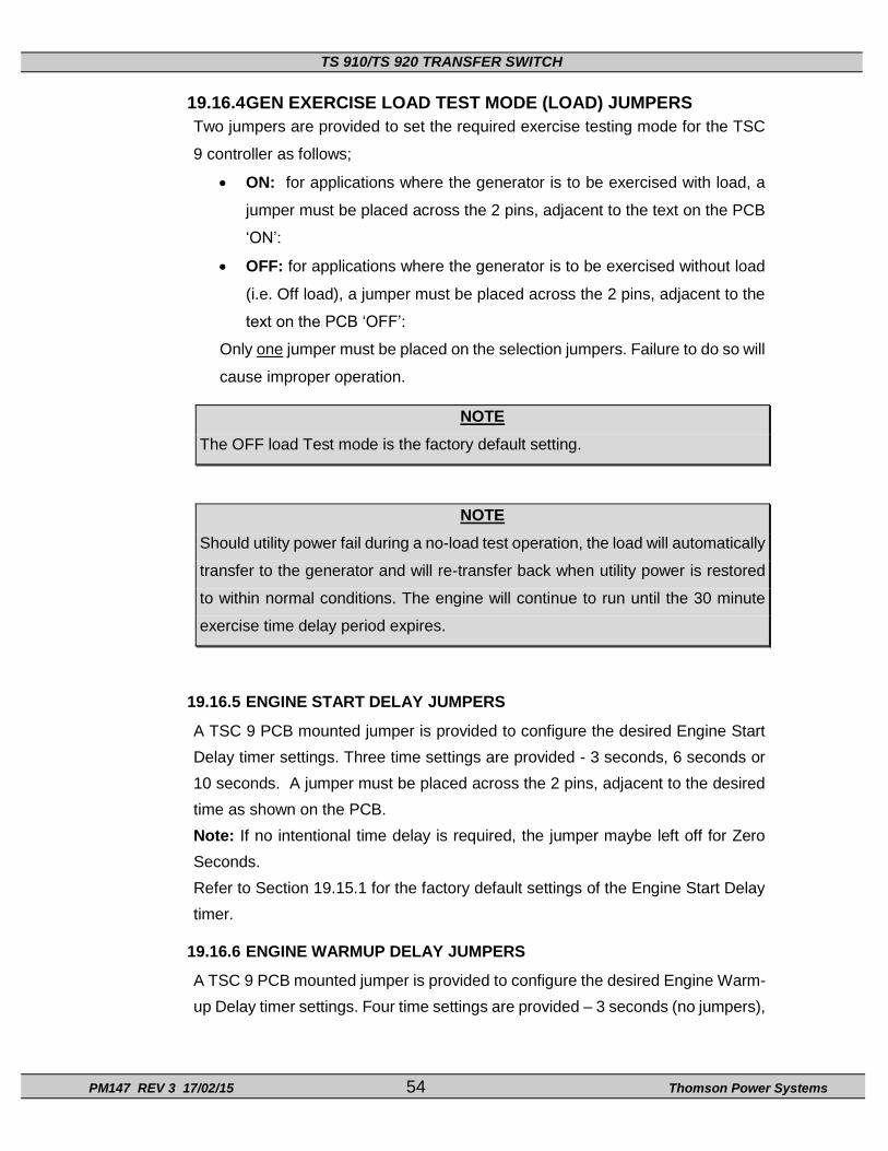
TS 910/TS 920 TRANSFER SWITCH
PM147 REV 3 17/02/15 54 Thomson Power Systems
19.16.4 GEN EXERCISE LOAD TEST MODE (LOAD) JUMPERS
Two jumpers are provided to set the required exercise testing mode for the TSC
9 controller as follows;
ON: for applications where the generator is to be exercised with load, a
jumper must be placed across the 2 pins, adjacent to the text on the PCB
‘ON’:
OFF: for applications where the generator is to be exercised without load
(i.e. Off load), a jumper must be placed across the 2 pins, adjacent to the
text on the PCB ‘OFF’:
Only one jumper must be placed on the selection jumpers. Failure to do so will
cause improper operation.
NOTE
The OFF load Test mode is the factory default setting.
NOTE
Should utility power fail during a no-load test operation, the load will automatically
transfer to the generator and will re-transfer back when utility power is restored
to within normal conditions. The engine will continue to run until the 30 minute
exercise time delay period expires.
19.16.5 ENGINE START DELAY JUMPERS
A TSC 9 PCB mounted jumper is provided to configure the desired Engine Start
Delay timer settings. Three time settings are provided - 3 seconds, 6 seconds or
10 seconds. A jumper must be placed across the 2 pins, adjacent to the desired
time as shown on the PCB.
Note: If no intentional time delay is required, the jumper maybe left off for Zero
Seconds.
Refer to Section 19.15.1 for the factory default settings of the Engine Start Delay
timer.
19.16.6 ENGINE WARMUP DELAY JUMPERS
A TSC 9 PCB mounted jumper is provided to configure the desired Engine Warm-
up Delay timer settings. Four time settings are provided – 3 seconds (no jumpers),
TS 910/TS 920 TRANSFER SWITCH
PM147 REV 3 17/02/15 55 Thomson Power Systems
10 seconds, 30 seconds or 60 seconds. A jumper must be placed across the 2
pins, adjacent to the desired time as shown on the PCB.
Refer to Section 19.15.1 for the factory default settings of the Engine Warm-up
Delay timer
19.16.7 ENGINE COOL DOWN DELAY JUMPERS
A TSC 9 PCB mounted jumper is provided to configure the desired Engine Cool
down Delay timer settings Four time settings are provided – 3 seconds (no
jumpers),1 minute, 2 minutes or 5 minutes. A jumper must be placed across the
2 pins, adjacent to the desired time as shown on the PCB.
Refer to Section 19.15.1 for the factory default settings of the Engine Cool down
Delay timer
19.16.8 UTILITY RETURN DELAY JUMPERS
A TSC 9 PCB mounted jumper is provided to configure the desired Utility Return
Delay timer settings. Four time settings are provided – 3 seconds (no jumpers),
10 seconds, 60 seconds or 120 seconds. A jumper must be placed across the 2
pins, adjacent to the desired time as shown on the PCB.
Refer to Section 19.15.1 for the factory default settings of the Utility Return Delay
timer
19.16.9 CURRENT TRANSFORMER SIZE JUMPERS
A TSC 9 PCB mounted jumper is provided to configure the size of current transformers
which are utilized when the kW Load shed option is used with the transfer switch. When
the kW Load shed option is not used, no jumper setting is required. Additional
information on TS 910/920 kW Load shed optional accessory can be obtained from our
Website (www.thomsonPS.com ).
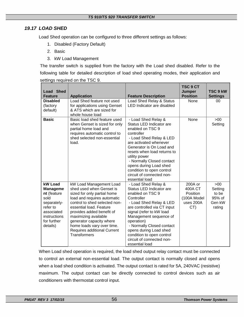
TS 910/TS 920 TRANSFER SWITCH
PM147 REV 3 17/02/15 56 Thomson Power Systems
19.17 LOAD SHED
Load Shed operation can be configured to three different settings as follows:
1. Disabled (Factory Default)
2. Basic
3. kW Load Management
The transfer switch is supplied from the factory with the Load shed disabled. Refer to the
following table for detailed description of load shed operating modes, their application and
settings required on the TSC 9.
Load Shed Feature Application Feature Description
TSC 9 CT Jumper Position
TSC 9 kW Settings
Disabled (factory default)
Load Shed feature not used for applications using Genset & ATS which are sized for whole house load
Load Shed Relay & Status LED Indicator are disabled
None 00
Basic Basic load shed feature used when Genset is sized for only partial home load and requires automatic control to shed selected non-essential load.
- Load Shed Relay & Status LED Indicator are enabled on TSC 9 controller - Load Shed Relay & LED are activated whenever Generator is On Load and resets when load returns to utility power - Normally Closed contact opens during Load shed condition to open control circuit of connected non-essential load
None >00 Setting
kW Load Management (feature sold separately-refer to associated instructions for further details)
kW Load Management Load shed used when Genset is sized for only partial home load and requires automatic control to shed selected non-essential load. Feature provides added benefit of maximizing available generator capacity where home loads vary over time. Requires additional Current Transformers
- Load Shed Relay & Status LED Indicator are enabled on TSC 9 Controller - Load Shed Relay & LED are controlled via CT input signal (refer to kW load Management sequence of operation) - Normally Closed contact opens during Load shed condition to open control circuit of connected non-essential load
200A or 400A CT Position
(100A Model uses 200A
CT)
>00 Setting to be
95% of Gen kW
rating
When Load shed operation is required, the load shed output relay contact must be connected
to control an external non-essential load. The output contact is normally closed and opens
when a load shed condition is activated. The output contact is rated for 5A, 240VAC (resistive)
maximum. The output contact can be directly connected to control devices such as air
conditioners with thermostat control input.

TS 910/TS 920 TRANSFER SWITCH
PM147 REV 3 17/02/15 57 Thomson Power Systems
For controlling loads that do not have integral control inputs, suitably rated AC power contactor
panels must be used for interconnection with the Load Shed contact. Refer to following typical
connection example:
Additional information on TS 910/920 kW Load shed optional accessory can be obtained from our Website (www.thomsonPS.com).

TS 910/TS 920 TRANSFER SWITCH
PM147 REV 3 17/02/15 58 Thomson Power Systems
20 BHP Operator Interface Panel (TS 920 Series Only)
20.1 DESCRIPTION
A door mounted operator interface panel (Model “BHP”) is provided standard on all TS
920 Series Transfer Switches. It provides the same operator interface indicator lights and
control pushbuttons as are provided on the TSC 9 Controller front panel. The BHP is
interconnected to the TSC 9 Controller via single RS232 communication cable.

TS 910/TS 920 TRANSFER SWITCH
PM147 REV 3 17/02/15 59 Thomson Power Systems
21 TS 910/TS 920 SCHEMATIC DIAGRAM

TS 910/TS 920 TRANSFER SWITCH
PM147 REV 3 17/02/15 60 Thomson Power Systems
22 TROUBLESHOOTING
Symptom Possible Causes
Will not re-transfer to utility source upon restoration
- TSC 9 Isolation plug is disconnected
- A test mode has been activated (check TSC 9 status LED) - Utility voltage is below 80% rated voltage (check utility source
for adequate voltage) - A loose control connection - Defective utility solenoid coil - TSC 9 has incorrect voltage configuration jumper setting for
correct system voltage - Defective TSC 9 controller (verify output signals) - TSC 9 has “Transfer Fail” alarm activated as indicated by
flashing Load on Utility LED. Determine cause of alarm and rectify before TSC 9 is reset
- In-phase transfer control has not detected an ‘in-phase condition to permit transfer. Transfer switch will automatically bypass an in-phase transfer after 5 minutes
- There is a phase rotation difference between the Utility and Generator source. Change Power cabling to match both sources phase rotation
Will not transfer to generator source upon failure of utility source
- TSC 9 Isolation plug is disconnected
- Generator set not producing enough voltage/frequency or output circuit breaker open
- TSC 9 has incorrect voltage configuration jumper setting for correct system voltage
- Warm-up time delay function has not timed out yet (verify TSC 9 timer setting)
- A loose control connection - Defective generator solenoid - Defective TSC 9 controller (verify output signals with circuit
board mounted diagnostic LED’s) - TSC 9 has “Transfer Fail” alarm activated as indicated by
flashing Load on Generator LED. Determine cause of alarm and rectify before TSC 9 is reset
- If Utility voltage is present, In-phase transfer control has not detected an ‘in-phase condition to permit transfer. Transfer switch will automatically bypass an in-phase transfer after 5 minutes
- There is a phase rotation difference between the Utility and Generator source. Change Power cabling to match both sources phase rotation
Transfer to generator source without a power failure on the utility source
- A TEST or EXERCISE mode has been activated (check TSC 9 status LED)
- Utility supply voltage is less than 70% on one or both phases of nominal voltage
- Verify TSC 9 has correct voltage configuration jumper setting for system voltage
- Defective TSC 9 controller (verify output signals with circuit board mounted diagnostic LED’s)

TS 910/TS 920 TRANSFER SWITCH
PM147 REV 3 17/02/15 61 Thomson Power Systems
Symptom Possible Causes Generator does not start up or stop when it should
- Verify remote engine control panel is set for automatic mode Verify engine start wiring is on correct terminals of TSC 9 controller. Verify engine start wiring is not loose at transfer switch and/or at the engine control panel. Verify time delay setting of the TSC 9 controller Exercise test has been incorrectly cancelled before Genset has operated on load for 60 seconds minimum (refer to manual section 19.9.2). Exercise Alarm condition has been activated (Flashing Alarm LED light and Exercise Light Flashing Fast). Must reset TSC 9 alarm- Press and hold the “E” and “T” pushbutton together for 10 seconds until alarm LED goes out.
- -
No time delay when there should be
Generator Exerciser not operating correctly
23 REPLACEMENT PARTS Replacement parts are available for the transfer switch as follows:
NOTE
When ordering replacement parts please provide the following
information:
-Transfer Switch Model code (e.g. TS 910A100A)
-Transfer Switch Serial Number (e.g. MW-022345)
The above information can be found on the transfer switch
equipment rating plate located on the inside of the ATS door.

TS 910/TS 920 TRANSFER SWITCH
PM147 REV 3 17/02/15 62 Thomson Power Systems
Part ID Description
010955 100A, 2 Pole, 240V Power Contactor
010956 200A, 2 Pole, 240V Power Contactor
010957 400A, 2 Pole, 240V Power Contactor
011376 100A, 3 Pole, 240V Power Contactor
011377 200A, 3 Pole, 240V Power Contactor
011243 400A, 3 Pole, 240V Power Contactor
011073 Manual Handle (100A 2P/3P, 200A 2P)
011577 Manual Handle (200A 3P)
011074 Manual Handle (400A Mechanism 2P & 3P)
011069 Limit Switch 1 n/o, 1 n/c (all ATS Models)
NOTE
There are no user serviceable components located on the TSC
9 printed circuit board. If the TSC 9 controller is deemed to be
defective it must be returned to the Thomson Power Systems
Factory for repair or replacement. Please refer to Product
Return Policy section of this manual further information on
product return procedures required.
For other parts not listed, please contact Thomson Power Systems.

TS 910/TS 920 TRANSFER SWITCH
PM147 REV 3 17/02/15 63 Thomson Power Systems
24 PRODUCT RETURN POLICY
Thomson Power Systems uses a Return Material Authorization (RMA) process. Please complete the
Return Authorization Request Form (available on our web page) for return of goods, warranty
replacement/repair of defective parts, or credit consideration and fax to the appropriate department.
Returns only: Sales Fax (604) 888-5606
Warranty replacement/Warranty Repair: Service Fax (604) 888-3370.
Upon receipt of your request, Thomson Power Systems will confirm with a copy of our Order
Acknowledgement via fax advising the RMA number which should be used to tag the defective
controller prior to shipment.

TS 910/TS 920 TRANSFER SWITCH
PM147 REV 3 17/02/15 64 Thomson Power Systems
25 NOTES

TS 910/TS 920 TRANSFER SWITCH
PM147 REV 3 17/02/15 65 Thomson Power Systems
26 APPENDIX A – TYPICAL AUTOMATIC TRANSFER SWITCH COMMISSIONING PROCEDURES
a) PRE-ENERGIZATION CHECKS
1. Verify the generator and utility supply voltages are 120/240V (or 120/208V 3 Phase or 127/220V 3 phase) maximum.
2. Confirm power cable size is correct for the lugs supplied in the transfer switch (line, load, and neutral) and are properly torqued.
3. Confirm transfer switch has been adequately grounded per NEC requirements.
4. Confirm power cables have been meggered to ensure no cross phase connections or conduction to ground.
5. Check for mechanical damage.
6. Check no packaging materials or tools are left inside the transfer switch.
7. Verify control wiring connected to the pluggable terminal block is properly installed (i.e. no frayed ends, screw is tight, no damage, etc.).
8. Ensure TSC 9 Control Isolation Plug (J4) is inserted into the TSC 9 Controller prior to operation.
9. Verify TSC 9 controller jumpers are set to reflect desired operation.
10. Visually verify the transfer switch power contactor is closed in the utility position. The upper solenoid plungers will be pulled towards the upper coils (refer to photos below).
‘ 100A/200A Contactor Utility Position 400A Contactor Utility Position
11. Verify correct control wire interconnects have been installed to the generator set auto start/stop controls. Note: The ATS Engine Start contact CLOSES to start the engine and OPENS to stop the engine.
12. Ensure the inside of the transfer switch is clean from all dust, and other foreign materials.
13. Re-install enclosure door front cover and tighten all cover mounting screws.

TS 910/TS 920 TRANSFER SWITCH
PM147 REV 3 17/02/15 66 Thomson Power Systems
14. Visually verify on the transfer switch enclosure that there are no gaps, holes, or potential for water ingress.
b) EQUIPMENT ENERGIZATION
DANGER HAZARD OF ELECTRICAL SHOCK, EXPLOSION, OR ARC FLASH
This equipment must be serviced only by qualified electrical personnel utilizing safe work practices and appropriate Personal Protective Equipment (PPE).
Many components of this equipment operate at line voltage. DO NOT TOUCH. Use only electrically isolated tools.
Failure to do so may cause personal injury or death 1. Confirm Utility, Generator and loads can be energized in a safe manner.
2. Energize utility supply and confirm voltage is 120/240V (or 120/208V 3 Phase or 127/220V 3 phase) and phase rotation at the utility and load is correct.
NOTE
The Utility supply must be energized before the Generator supply for the
System Frequency “Auto-Detection” feature to work correctly.
3. Verify the status of the following indicator lights on the TSC 9 HMI faceplate: - Utility Source Green light is “ON” - Load on Utility Green light is “ON”
4. Run the generator manually and confirm generator supply voltage is 120/240V (or 120/208V 3 Phase or 127/220V 3 phase) and phase rotation matches to that of the Utility source and load.
NOTE
On 3 Phase Systems, the TSC 9 controller has Phase Rotation miss-match
protection. For the ATS to successfully transfer between sources, both the
Utility and Generator Source Phase rotation must be matched. Phase rotation
on both sources can be either positive rotation (i.e. A-B-C) or negative rotation
(C-B-A)
5. Verify the status of the following indicator lights on the TSC 9 HMI faceplate: - Generator Source Red Light is “ON”
6. Using appropriate personal protective equipment (PPE) and insulated tools/meters, remove the transfer switch front cover while energized.
7. Verify at the transfer switch (while energized), the utility and generator supply voltage, phasing and phase rotation is correct.
8. Manually stop generator and place the generator controls in the "AUTOMATIC" position.
9. To confirm automatic starting and load transferring of the generator, perform the following steps:
a) To test, press and hold the “T” pushbutton on the TSC 9 controller faceplate for 2 seconds until light above pushbutton comes ON. The generator will start and

TS 910/TS 920 TRANSFER SWITCH
PM147 REV 3 17/02/15 67 Thomson Power Systems
transfer on load per Automatic Sequence.
b) To determine correct operation, observe the following on the TSC 9 faceplate: - Gen Start Red light is “ON” - Gen Source Red light is “ON” - Load on Gen Red light is “ON
10. To stop the generator and transfer load back to the utility supply, press and hold the “T” pushbutton for 2 seconds until light above pushbutton goes OFF. The load will re-transfer back to the utility power as per Automatic Sequence.
11. Perform a utility power outage test by opening the upstream utility feeder breaker. The TSC 9 controller Utility supply light will turn off; the generator set will start after the 3-second engine start delay has expired, the generator should start and transfer on load as per Automatic Sequence.
12. Return the transfer switch to utility power by re-closing the upstream utility breaker. The load should re-transfer back to the utility supply as per Automatic Sequence.