ts-250 security policy - nist shown in figure 11, the cryptographic boundary of the ts- -250 for the...
TRANSCRIPT

Copyright © 2014 Fiber Logic Communication, Inc. This document may be reproduced only in its original entirety. [without revision] 1
TS-250
FIPS 140-2 Level 3 Validation Non-Proprietary Security Policy
Firmware Version 1.0.0.0
Hardware Version 1.0 Document Version 4.0
February 2014

Copyright © 2014 Fiber Logic Communication, Inc. This document may be reproduced only in its original entirety. [without revision] 2
TABLE OF CONTENTS 1. Introduction ................................................................................................................................. 4
1.1 TS-250 Module Overview ................................................................................................ 4 1.2 Cryptographic Module Boundary ................................................................................... 4 1.3 Security Level .................................................................................................................... 5
2. Mode of Operation ..................................................................................................................... 6 3. Ports and Interfaces .................................................................................................................. 7
3.1 Physical Port ..................................................................................................................... 7 3.2 Mapping of Logical Interfaces to Physical Ports .......................................................... 9
4. Physical Security ...................................................................................................................... 10 5. Critical Security Parameters ................................................................................................... 11 6. Identification and Authentication Policy ................................................................................ 11
6.1 Roles ................................................................................................................................ 11 6.2 Services ........................................................................................................................... 12 6.3 Authentication Mechanisms .......................................................................................... 15
7. Operational Environment ........................................................................................................ 16 8. Cryptographic Key Management ........................................................................................... 16
8.1 Key Generation Method ................................................................................................ 16 8.2 Key Establishment Method ........................................................................................... 16 8.3 Key Transport .................................................................................................................. 16 8.4 Key Storage ..................................................................................................................... 17
9. Self-Tests ................................................................................................................................... 17 10. EMI/EMC ................................................................................................................................... 18 11. Design Assurance .................................................................................................................... 18
11.1 Configuration Management System ............................................................................ 18 11.2 Delivery and Operation .................................................................................................. 19
12. Security Rules .......................................................................................................................... 19 13. Mitigation of Other Attacks ..................................................................................................... 20 14. Acronyms and Abbreviations ................................................................................................. 20

Copyright © 2014 Fiber Logic Communication, Inc. This document may be reproduced only in its original entirety. [without revision] 3
LIST OF TABLES Table 1-1 Module Security Level Specification ............................................................................ 5 Table 3-1 Physical Port Description ............................................................................................... 8 Table 3-2 Mapping of Logical Interfaces to Physical Ports ........................................................ 9 Table 6-1 Default Operators .......................................................................................................... 11 Table 6-2 Module Services Description ...................................................................................... 12 Table 6-3 Roles and Authenticated Services ............................................................................. 14 Table 6-4 Roles with Required Authentication ........................................................................... 15 Table 6-5 Estimated Strength of Authentication Mechanisms ................................................. 15 Table 9-1 Self-Test List .................................................................................................................. 17 Table 14-1 Acronym and Definition.............................................................................................. 20
LIST OF FIGURES
Figure 1-1 TS-250 Module Boundary ..................................................................................4 Figure 1-2 Logical Block Diagram .......................................................................................5 Figure 3-1 TS-250 Front and Rear View .............................................................................8 Figure 4-1 Tamper-Evident Labels .................................................................................... 10

Copyright © 2014 Fiber Logic Communication, Inc. This document may be reproduced only in its original entirety. [without revision] 4
1. Introduction 1.1 TS-250 Module Overview
For FIPS 140-2 Level 3 validation, the TS-250 module has been validated as a Multiple-Chip Standalone cryptographic module.
The TS-250 can encrypt the high speed network traffic passed through. The module can be configured to encrypt different layer of network traffic, e.g., from Ethernet frame payload or from IP packet payload.
1.2 Cryptographic Module Boundary
As shown in Figure 1-1, the cryptographic boundary of the TS-250 for the FIPS 140-2 Level 3 validation is the outer perimeter of the metal enclosure that encompasses all critical security components.
Figure 1-1 TS-250 Module Boundary

Copyright © 2014 Fiber Logic Communication, Inc. This document may be reproduced only in its original entirety. [without revision] 5
The logical block diagram of TS-250 module is shown as Figure 1-2.
Figure 1-2 Logical Block Diagram
1.3 Security Level
The module meets the overall requirements applicable to FIPS 140-2 Level 3.
Table 1-1 Module Security Level Specification
Security Requirements Section Level
Cryptographic Module Specification 3 Module Ports and Interfaces 3 Roles, Services and Authentication 3 Finite State Model 3 Physical Security 3 Operational Environment N/A Cryptographic Key Management 3 EMI/EMC 3 Self-Tests 3 Design Assurance 3 Mitigation of Other Attacks N/A

Copyright © 2014 Fiber Logic Communication, Inc. This document may be reproduced only in its original entirety. [without revision] 6
2. Mode of Operation The module has two modes of operation: Approved mode and non-Approved mode.
The module runs in the Approved mode by default. The module is considered running in the non-Approved mode when the module performs non-Approved security functions. CSPs defined in an Approved mode of operation will not be accessed or shared while in a non-Approved mode of operation. The FIPS Mode LED will be lighted ON while the module operates at Approved mode. Operator can execute “Show Status” service from CLI to show the current mode of operation. Any change between modes will force the module to power cycle.
All packets on data interface are protected by encryption with AES algorithm. The data session keys for encryption are imported from external key loader or (non-Approved mode only) established with Data Diffie-Hellman key exchange procedure.
TS-250 supports following cryptographic algorithms.
1. AES (Certificate #1903) Encrypt/Decrypt ECB/CBC/CFB128/OFB modes Key lengths 128/192/256-bit
2. DSA (Certificate #601) FIPS186-3: Signature generation/verification
3. SHA (Certificate #1673) SHA1/224/256/384/512 (Byte-only)
4. HMAC-SHA (Certificate #1143) HMAC-SHA1/224/256/384/512
5. RNG (Certificate #997) ANSI X9.31: AES128
6. RNG (Certificate #1000) ANSI X9.31: AES128/192/256
7. Hardware RNG (FIPS-allowed) 8. AES (Cert. #1903, key wrapping) (only used in non-Approved mode of operation) 9. Diffie-Hellman (key agreement; key establishment methodology provides 112 bits of
encryption strength) (non-FIPS approved only used in non-Approved mode of operation) Diffie-Hellman key establishment for SSHv2 Session Key Diffie-Hellman key establishment for Data Session Key
Note:
Some of the previously validated components for algorithm validations have been removed because

Copyright © 2014 Fiber Logic Communication, Inc. This document may be reproduced only in its original entirety. [without revision] 7
they are now non-compliant per the SP800-131A transition. Please refer to CAVP algorithm validation
lists and NIST Special Publication 800-131A for more information.
1. DSA (Certificate #601)
Digital signature generation: After December 31, 2013, key lengths providing less than 112 bits
of security strength shall not be used to generate digital signatures. Key lengths providing at
least 112 bits of security are acceptable.
Digital signature verification: Key lengths providing 80 bits of security using approved digital
signature algorithms are allowed for legacy-use after 2010.
2. SHA (Certificate #1673)
SHA-1 digital signature generation: After December 31, 2013, users of the module should
select a strong hash function and no longer use SHA-1 for digital signature generation.
SHA-1 for digital signature verification: For digital signature verification, SHA-1 is allowed for
legacy-use after December 31, 2010.
SHA-1 for non-digital signature applications: For all other hash function applications, the use of
SHA-1 is acceptable.
SHA-224, SHA-256, SHA-384, SHA-512: The use of these hash functions is acceptable for all
hash function applications.
3. HMAC-SHA (Certificate #1143)
HMAC Generation: Any approved hash function may be used. After December 31, 2013, key
lengths < 112 bits shall not be used. The use of key lengths ≥ 112 bits is acceptable.
HMAC Verification: The use of key lengths ≥ 80 bits, but < 112 bits is allowed for legacy-use
after December 31, 2010. The use of key lengths ≥ 112 bits is acceptable.
AES, SHA and HMAC must be the only algorithms used in the Approved mode of operation. Once the SSH or Data DH service is enabled, the module will operate at non-Approved mode. The module does not share CSPs between an Approved mode of operation and a non-Approved mode of operation. All cryptographic keys used in the Approved mode of operation must be imported while running in the Approved mode.
3. Ports and Interfaces 3.1 Physical Port
Please refer to module front/rear view shown as Figure 3-1, and physical port description listed as Table 3-1.

Copyright © 2014 Fiber Logic Communication, Inc. This document may be reproduced only in its original entirety. [without revision] 8
Figure 3-1 TS-250 Front and Rear View
Table 3-1 Physical Port Description
Physical Port Description Plain port DB9 Ethernet port for plaintext data in/out Cipher port DB9 Ethernet port for iphertext data in/out Console port DB9 console Port KeyIn port DB9 key input port Eth port Management port Key-Reset Button Key erase Reset Button System reset Power Connector +12V Power pin +12V input
RTN Ground pin FG Frame ground pin
Power Switch Power on/off LEDs Power Indicates cryptographic module’s power status.
Alarm Indicates cryptographic module’s alarm status. Alarm conditions are listed as follow:
1. Power-up self-tests fail 2. Imported Keys for current mode of operation don’t exist.
FIPS MODE If the LED light is on, it indicates module is at Approved mode of operation.
ENC/DEC Indicates the module is performing data encryption & decryption.
Key Indicates whether cryptographic module’s keys exist.
Plain 10/100 Plain port speed status
Front Rear

Copyright © 2014 Fiber Logic Communication, Inc. This document may be reproduced only in its original entirety. [without revision] 9
Physical Port Description Plain Link/Act Plain port link/active status Cipher 10/100 Cipher port speed status Cipher Link/Act Cipher port link/active status Eth 10/100 Eth port speed status Eth Link/Act Eth port link/active status
3.2 Mapping of Logical Interfaces to Physical Ports
All of the physical ports are separated into logical interfaces defined by FIPS 140-2, as described in the following table:
Table 3-2 Mapping of Logical Interfaces to Physical Ports
FIPS 140-2 Logical Interface Physical Port
Data Input Plain port Cipher port Eth port Console port KeyIn port
Data Output Plain port Cipher port
Control Input Eth port Console port Key-Reset Button Reset Button Power Switch
Status Output Eth port Console port LEDs
Power Power Connector

Copyright © 2014 Fiber Logic Communication, Inc. This document may be reproduced only in its original entirety. [without revision] 10
4. Physical Security TS-250 is a Multiple-Chip Standalone cryptographic module, as defined by FIPS 140-2
and is designed to meet level 3 physical security requirements. It is protected by a strong metal production-grade enclosure that is resistant to probing and is opaque within the visible spectrum. Around the rear cover (please refer to Figure 4-1), four white round tamper-evident fragile labels are pasted to provide evidence of tampering when physical access to the module is attempted. The tamper evident labels are applied at the factory to provide evidence of tampering if a panel is removed. For running in the Approved mode of operation, the Crypto-Officer must check the integrity of the tamper evident labels upon receipt of the module and periodically thereafter. Upon discovery of tampering the Crypto-Officer must immediately disable the module and return the module to the manufacturer.
The TS-250 module has a removable rear cover which is protected by tamper response circuitry. When rear cover is removed or the photosensitive sensor detects light or the key zeroization push bottom is pushed, the module will trigger zeroization circuitry to cut off SRAM (key storage IC) power, then the keys & CSPs stored in SRAM will be zeroized.
The TS-250 module has internal Li-ion battery that provides power to SRAM and zeroization circuitry. When the module is powered off, the keys in SRAM will still keep alive and zeroization circuitry will be still working until battery is exhausted.
Figure 4-1 Tamper-Evident Labels

Copyright © 2014 Fiber Logic Communication, Inc. This document may be reproduced only in its original entirety. [without revision] 11
5. Critical Security Parameters The following are the Critical Security Parameters (CSPs) used in the module.
Table 5-1 Critical Security Parameters
CSPs CSP type Generation Use Stored Zeroized
Data session keys
128/192/256-bit AES keys;
Imported from KeyIn port.
Secure data traffic. Battery backed SRAM
1.On tamper detected 2.“Zeroize keys &
CSPs” service. 3. Key reset button is
triggered. HMAC key Fixed
length, 512-bits HMAC key
Imported from KeyIn port.
Used for checking firmware integrity and authentication code during firmware load test.
Battery backed SRAM
1.On tamper detected 2.“Zeroize keys &
CSPs” service. 3. Key reset button is
triggered. Key wrapping key
256-bit AES key
Imported from KeyIn port.
Used to encrypt keys imported into the module using external key loader.
Battery backed SRAM
1.On tamper detected 2.“Zeroize keys &
CSPs” service. 3. Key reset button is
triggered. Username/Password
Operator username,6~20 characters password
Entered by operators
Authentication for accessing the management interface.
Battery backed SRAM
1.On tamper detected 2.“Zeroize keys &
CSPs” service. 3. Key reset button is
triggered.
6. Identification and Authentication Policy 6.1 Roles
The TS-250 cryptographic module supports identity-based authentication. There are two roles in the module (as required by FIPS 140-2 Level 3) that operator may assume: Crypto-Officer role and User role. The module has two default operators: co and user.
Table 6-1 Default Operators
Username Role
co Crypto-Officer
user User

Copyright © 2014 Fiber Logic Communication, Inc. This document may be reproduced only in its original entirety. [without revision] 12
Default operator have default password for the first time the module is accessed. If default password is used for default operator, only “Change Own Password” service is allowed to be executed. After changing password, default operator can execute all relative services. Only Crypto-Officer Role operator can create a new operator, and chooses the role for the new operator. Default operators cannot be deleted.
The CLI can be accessed locally over the serial Console port or (non-Approved mode only) remotely by using the SSHv2 secured management session over the Eth port. When an operator successfully login the module, the authorized role is allowed. The operator is allowed to perform authorized services for monitoring and configuration. 6.2 Services
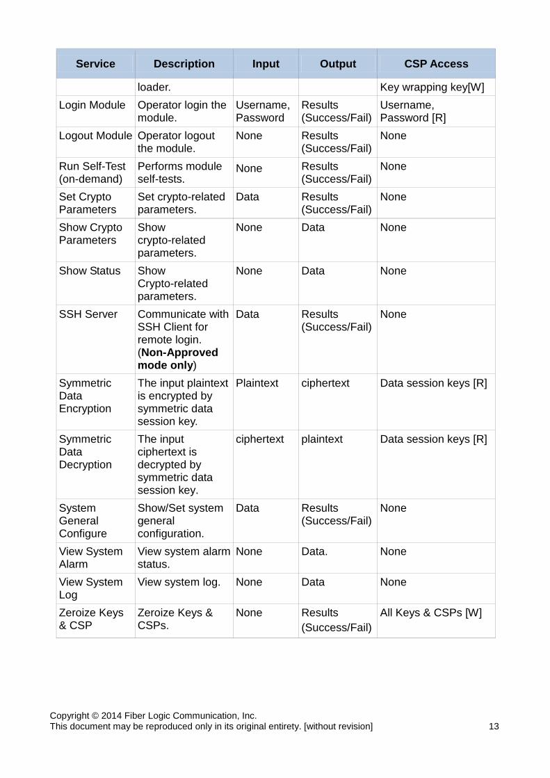
The keys and CSPs listed in Table 6-2 indicate the type of access required using the following notation:
[R]: The CSP is read [W]: The CSP is established, generated, modified, or zeroized
Table 6-2 Module Services Description
Service Description Input Output CSP Access
Change Own Password
Operator changes its own password.
Password Results (Success/Fail)
Password [W]
Clear System Alarm
Clear system alarm history record.
None Results (Success/Fail)
None
Clear System Log
Clear system log history record.
None Results (Success/Fail)
None
Create Operator
Create new operator.
Username, Password
Results (Success/Fail)
Username, Password [W]
Crypto Key-Exchange
Data Diffie-Hellman key exchange procedure. (Non-Approved mode only)
Data Results (Success/Fail)
None
Delete Operator
Delete operator. Username Results (Success/Fail)
Username, Password [W]
Firmware Upgrade
Upgrade Firmware though FTP.
Data Results (Success/Fail)
HMAC Key [R]
Import Keys Import Keys from external key
Keys Results (Success/Fail)
Data session keys[W], HMAC key[W],
Copyright © 2014 Fiber Logic Communication, Inc. This document may be reproduced only in its original entirety. [without revision] 13
Service Description Input Output CSP Access
loader. Key wrapping key[W] Login Module Operator login the
module. Username, Password
Results (Success/Fail)
Username, Password [R]
Logout Module Operator logout the module.
None Results (Success/Fail)
None
Run Self-Test (on-demand)
Performs module self-tests.
None Results (Success/Fail)
None
Set Crypto Parameters
Set crypto-related parameters.
Data Results (Success/Fail)
None
Show Crypto Parameters
Show crypto-related parameters.
None Data None
Show Status Show Crypto-related parameters.
None Data None
SSH Server Communicate with SSH Client for remote login. (Non-Approved mode only)
Data Results (Success/Fail)
None
Symmetric Data Encryption
The input plaintext is encrypted by symmetric data session key.
Plaintext ciphertext Data session keys [R]
Symmetric Data Decryption
The input ciphertext is decrypted by symmetric data session key.
ciphertext plaintext Data session keys [R]
System General Configure
Show/Set system general configuration.
Data Results (Success/Fail)
None
View System Alarm
View system alarm status.
None Data. None
View System Log
View system log. None Data None
Zeroize Keys & CSP
Zeroize Keys & CSPs.
None Results (Success/Fail)
All Keys & CSPs [W]
Copyright © 2014 Fiber Logic Communication, Inc. This document may be reproduced only in its original entirety. [without revision] 14
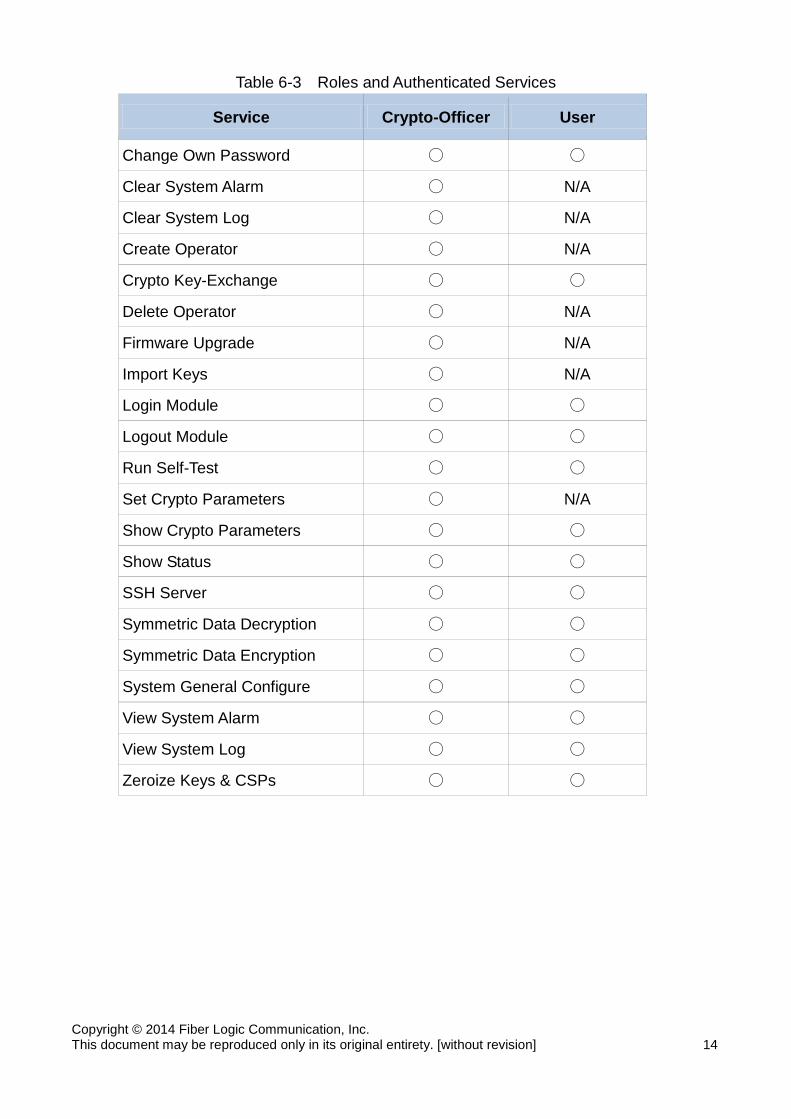
Table 6-3 Roles and Authenticated Services
Service Crypto-Officer User
Change Own Password ○ ○
Clear System Alarm ○ N/A
Clear System Log ○ N/A
Create Operator ○ N/A
Crypto Key-Exchange ○ ○
Delete Operator ○ N/A
Firmware Upgrade ○ N/A
Import Keys ○ N/A
Login Module ○ ○
Logout Module ○ ○
Run Self-Test ○ ○
Set Crypto Parameters ○ N/A
Show Crypto Parameters ○ ○
Show Status ○ ○
SSH Server ○ ○
Symmetric Data Decryption ○ ○
Symmetric Data Encryption ○ ○
System General Configure ○ ○
View System Alarm ○ ○
View System Log ○ ○
Zeroize Keys & CSPs ○ ○
Copyright © 2014 Fiber Logic Communication, Inc. This document may be reproduced only in its original entirety. [without revision] 15
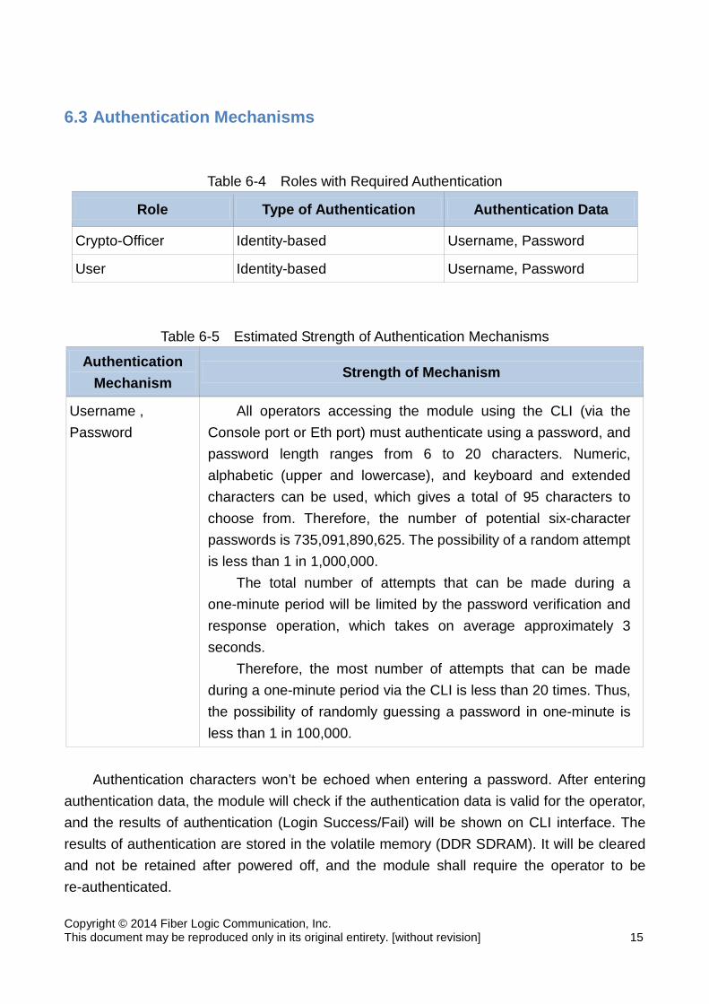
6.3 Authentication Mechanisms
Table 6-4 Roles with Required Authentication
Role Type of Authentication Authentication Data
Crypto-Officer Identity-based Username, Password
User Identity-based Username, Password
Table 6-5 Estimated Strength of Authentication Mechanisms
Authentication Mechanism
Strength of Mechanism
Username , Password
All operators accessing the module using the CLI (via the Console port or Eth port) must authenticate using a password, and password length ranges from 6 to 20 characters. Numeric, alphabetic (upper and lowercase), and keyboard and extended characters can be used, which gives a total of 95 characters to choose from. Therefore, the number of potential six-character passwords is 735,091,890,625. The possibility of a random attempt is less than 1 in 1,000,000.
The total number of attempts that can be made during a one-minute period will be limited by the password verification and response operation, which takes on average approximately 3 seconds.
Therefore, the most number of attempts that can be made during a one-minute period via the CLI is less than 20 times. Thus, the possibility of randomly guessing a password in one-minute is less than 1 in 100,000.
Authentication characters won’t be echoed when entering a password. After entering
authentication data, the module will check if the authentication data is valid for the operator, and the results of authentication (Login Success/Fail) will be shown on CLI interface. The results of authentication are stored in the volatile memory (DDR SDRAM). It will be cleared and not be retained after powered off, and the module shall require the operator to be re-authenticated.
Copyright © 2014 Fiber Logic Communication, Inc. This document may be reproduced only in its original entirety. [without revision] 16
7. Operational Environment The FIPS 140-2 Area 6 Operational Environment requirements are not applicable
because the cryptographic module supports a limited operational environment.
8. Cryptographic Key Management
8.1 Key Generation Method
The module generates ephemeral key pair during data DH and SSH DH only in non-Approved mode of operation. 8.2 Key Establishment Method
The two key establishment methods listed below are for non-Approved mode only.
1. Data Diffie-Hellman: The Data Diffie-Hellman is used to establish Data session keys between modules
for secure data traffic.
2. SSHv2 Diffie-Hellman: The SSHv2 Diffie-Hellman is used to establish SSH session keys between module
and remote SSH client for secure communication connection. 8.3 Key Transport
All cryptographic keys imported from external key loader are in encrypted form, and are not exported. The secret and private keys entered into the module are encrypted by external key loader using Approved algorithm (AES CBC mode). The external key loader communicates with the module using the KeyIn port. The operator uses the console interface to operate the process. The operator chooses keys to import to the module secondly. Finally, the operator waits for the “successful” message and these keys would be stored in the Battery Backed SRAM. All the datagrams through the KeyIn port are encrypted using Approved algorithm (AES CBC mode). Importing keys failure will result the module entering into error state.
Copyright © 2014 Fiber Logic Communication, Inc. This document may be reproduced only in its original entirety. [without revision] 17
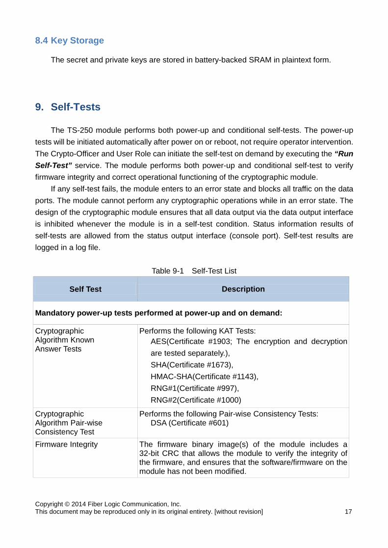
8.4 Key Storage The secret and private keys are stored in battery-backed SRAM in plaintext form.
9. Self-Tests The TS-250 module performs both power-up and conditional self-tests. The power-up
tests will be initiated automatically after power on or reboot, not require operator intervention. The Crypto-Officer and User Role can initiate the self-test on demand by executing the “Run Self-Test” service. The module performs both power-up and conditional self-test to verify firmware integrity and correct operational functioning of the cryptographic module.
If any self-test fails, the module enters to an error state and blocks all traffic on the data ports. The module cannot perform any cryptographic operations while in an error state. The design of the cryptographic module ensures that all data output via the data output interface is inhibited whenever the module is in a self-test condition. Status information results of self-tests are allowed from the status output interface (console port). Self-test results are logged in a log file.
Table 9-1 Self-Test List
Self Test Description
Mandatory power-up tests performed at power-up and on demand:
Cryptographic Algorithm Known Answer Tests
Performs the following KAT Tests: AES(Certificate #1903; The encryption and decryption are tested separately.), SHA(Certificate #1673), HMAC-SHA(Certificate #1143), RNG#1(Certificate #997), RNG#2(Certificate #1000)
Cryptographic Algorithm Pair-wise Consistency Test
Performs the following Pair-wise Consistency Tests: DSA (Certificate #601)
Firmware Integrity The firmware binary image(s) of the module includes a 32-bit CRC that allows the module to verify the integrity of the firmware, and ensures that the software/firmware on the module has not been modified.

Copyright © 2014 Fiber Logic Communication, Inc. This document may be reproduced only in its original entirety. [without revision] 18
Self Test Description
Conditional tests performed, as needed, during operation:
Firmware Load The digital signature of the loaded firmware is generated using HMAC-SHA256. If the digital signature matches the test passes, otherwise it fails and the firmware will not be loaded.
Continuous RNG This test is to check the RNG output data for failure to a constant value. All internal RNGs are subject to this test (RNG#1, RNG#2 and HRNG). Each generated block will be compared with the previously generated block. The test will be failed if any two compared blocks are equal, and the module will be entered into error state.
During the known answer tests for cryptographic algorithm, the module compares the
calculated output with the known answer. If the calculated output does not equal the known answer, the known-answer test shall fail. Cryptographic algorithms whose outputs vary for a given set of inputs (e.g., the Digital Signature Algorithm) will be tested using a pair-wise consistency test.
The two Approved RNGs(Certificate #997 and #1000)/non-Approved RNG(HRNG) produces blocks of 128/32 bits, the first 128/32-bit block generated after power-up initialization, or reset will not be used, but will be saved for comparison with the next 128/32-bit block to be generated.
10. EMI/EMC TS-250 module conforms to the Electromagnetic Interference/ Electromagnetic
Compatibility (EMI/EMC) requirements specified by 47 Code of Federal Regulations, Part 15, Subpart B, Unintentional Radiators, Digital Devices, and Class B (for home use).
11. Design Assurance 11.1 Configuration Management System
A Git server is set up as the configuration management system of TS-250 module. All software/firmware/hardware source code and associated module documentation for the module are stored in Git server. Each version of each configuration item is assigned and

Copyright © 2014 Fiber Logic Communication, Inc. This document may be reproduced only in its original entirety. [without revision] 19
labeled with a unique identification number. All software and firmware components within the cryptographic module are
implemented using a high-level language.
11.2 Delivery and Operation The security during delivery is guaranteed by courier delivery services company such as
DHL, FedEx etc. While receiving the module package, authorized operators should check whether the package remains intact. If the authorized operators suspect that the package is been opened during delivery, they should immediately contact Fiber Logic Communications, Inc.
12. Security Rules The cryptographic module design corresponds to the cryptographic module security rules.
This section documents the security rules enforced by the cryptographic module to implement the security requirements of a FIPS 140-2 Level 3 module. The cryptographic module provides identity‐based authentication with two distinct
operator roles. These are the User role, and the Crypto-Officer role. The cryptographic module doesn’t support concurrent operators, and doesn’t permit
an operator to change role, and there is no Maintenance role associated with the module.
Data output is inhibited during key generation, self-tests, zeroization, and error states. Status information does not contain CSPs or sensitive data that if misused could lead
to a compromise of the modules. The module does not support bypass modes. All authentication data can only be accessed by authorized roles. Both the CO and User shall examine the enclosure regularly and see if there are
signs of tamper attempts. If damage to the tamper-evident labels is found, then the device is not considered operating in the Approved mode of operation.
The module does not output intermediate key generation values. All Cryptographic Keys and CSPs imported from external key loader are in encrypted
form, and are not exported. The power-up tests will be initiated automatically after power on or reboot, not require
operator intervention. The Crypto-Officer and User Role can initiate the self-test on demand by executing the ‘self-test’ CLI command.

Copyright © 2014 Fiber Logic Communication, Inc. This document may be reproduced only in its original entirety. [without revision] 20
13. Mitigation of Other Attacks The module has not been designed to mitigate against specific attacks as described in
FIPS 140‐2 Area 11.
14. Acronyms and Abbreviations Table 14-1 Acronym and Definition
Acronym Definition AES Advanced Encryption Standard CAVP Cryptographic Algorithm Validation Program CBC Cipher Block Chaining CFB Cipher Feedback CLI Command Line Interface CO Cryptographic Officer CSP Critical Security Parameter DH Diffie-Hellman DSA Digital Signature Algorithm ECB Electronic Codebook EMC Electromagnetic Compatibility EMI Electromagnetic Interference FIPS Federal Information Processing Standards HMAC Hash Message Authentication Code HRNG Hardware Random Number Generator KAT Known Answer Test OFB Output Feedback RNG Random Number Generator SHA Secure Hash Algorithm SRAM Static Random Access Memory SSH Secure Shell